Belkin F5D9630-4 ADSL2+ Modem with Wireless G Plus MIMO Router User Manual P75125uk F5D9630ukcoverchange indd
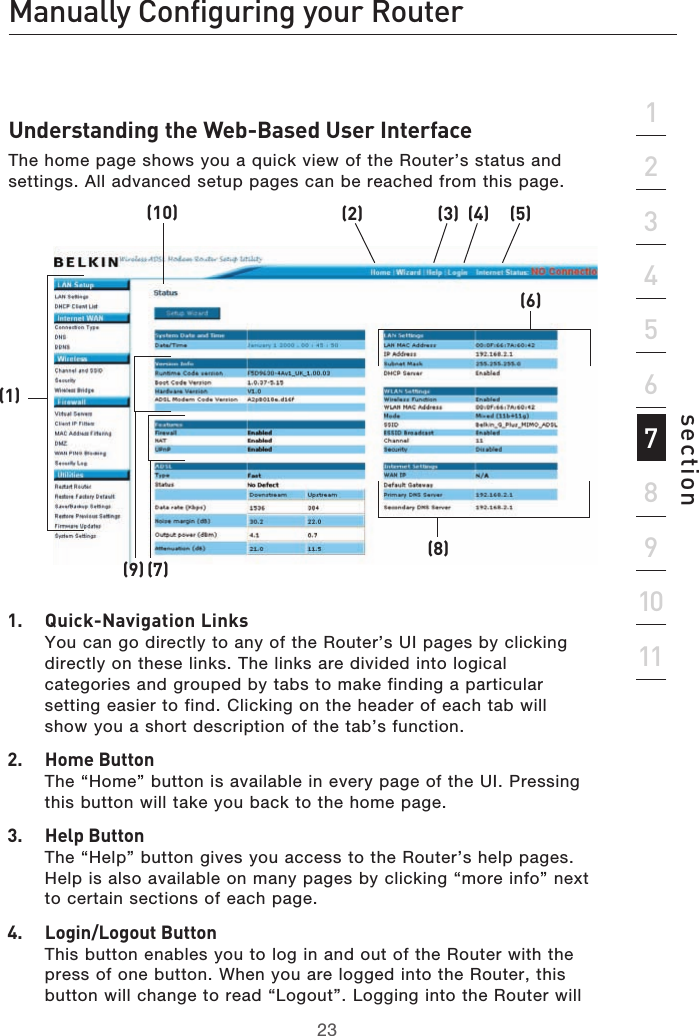
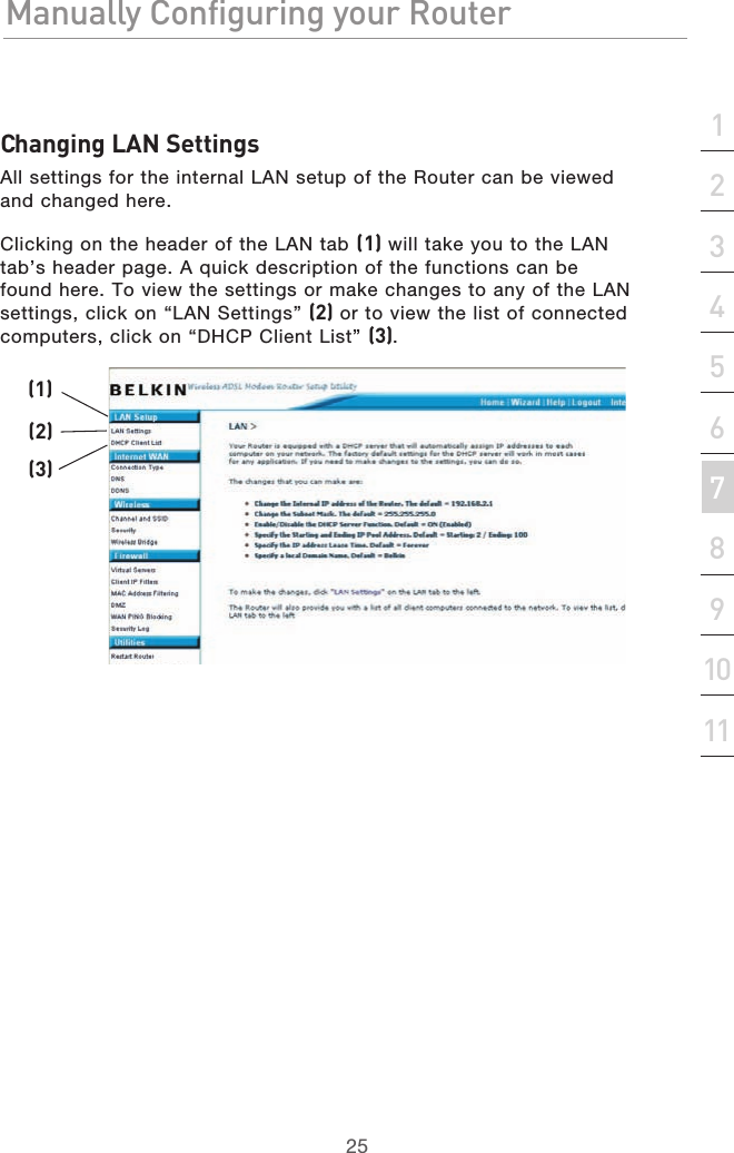
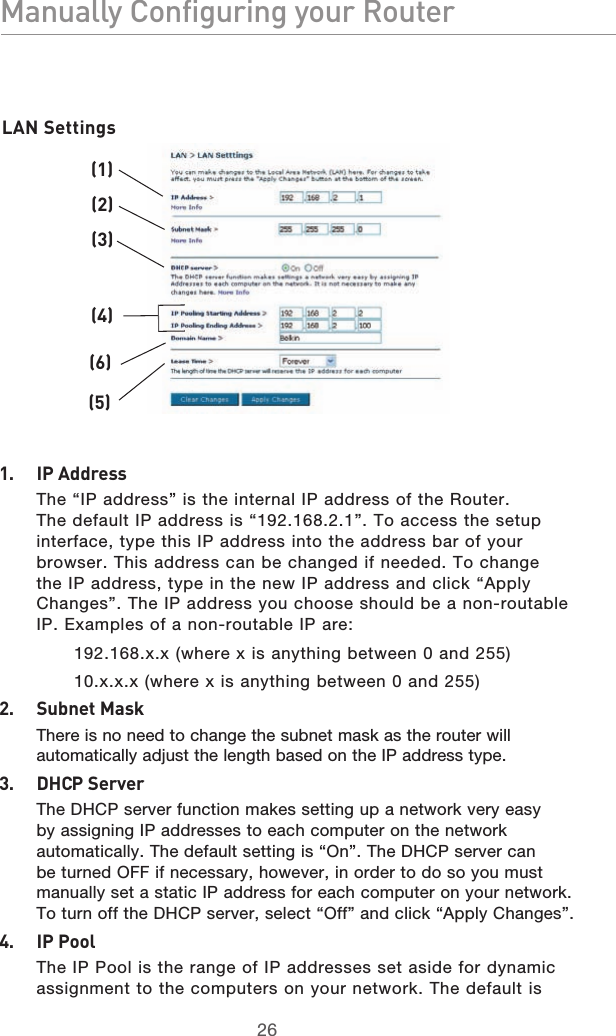
Belkin International, Inc. ADSL2+ Modem with Wireless G Plus MIMO Router P75125uk F5D9630ukcoverchange indd
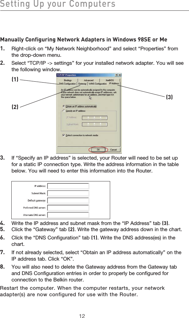
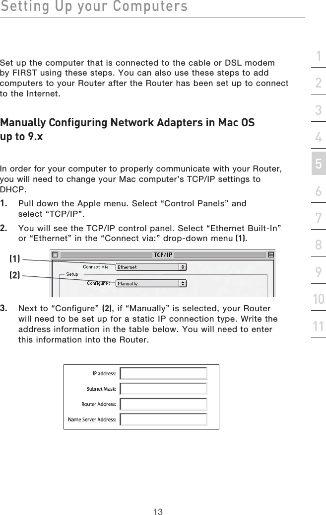
Belkin >
Contents
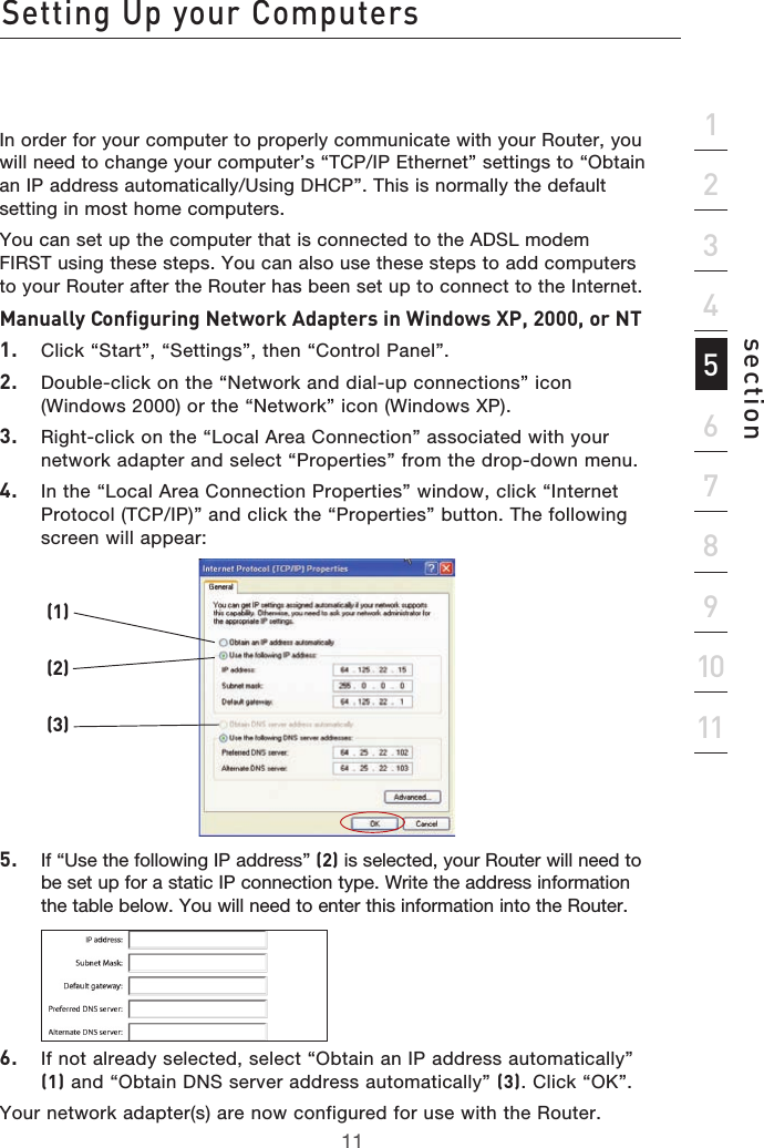
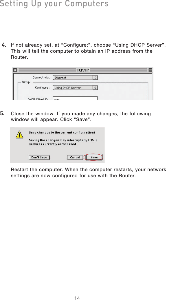
- 1. Manual 1
- 2. Manual 2
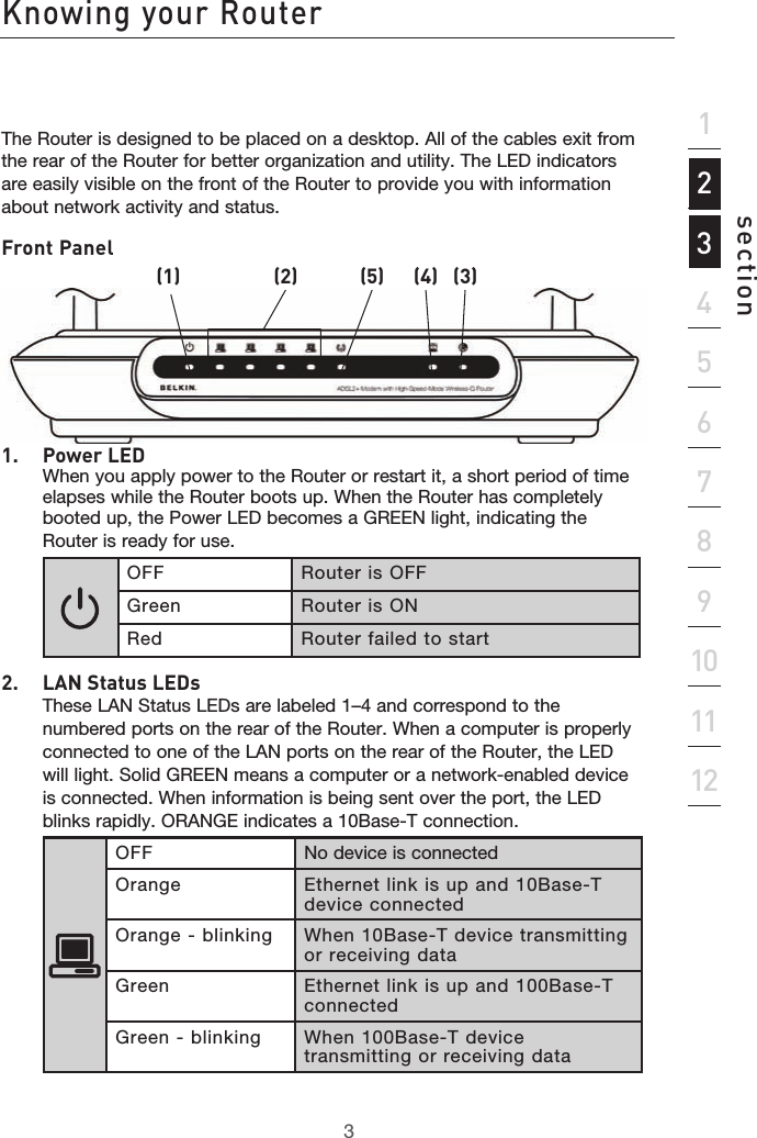
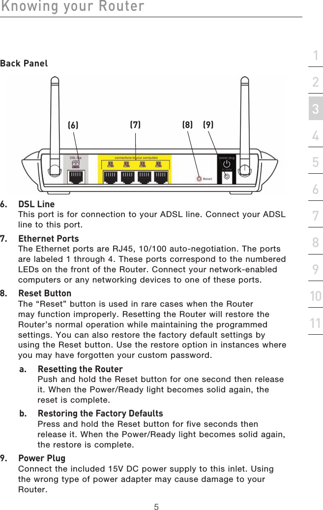
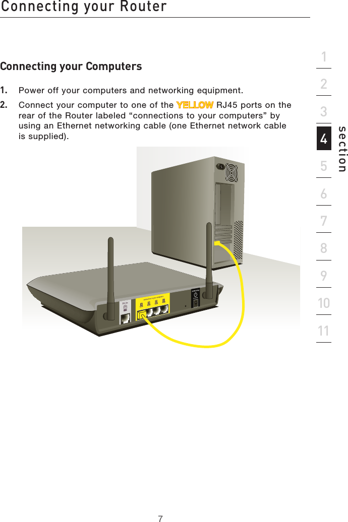
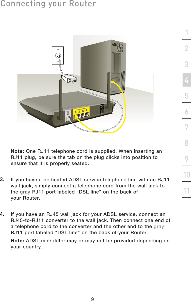
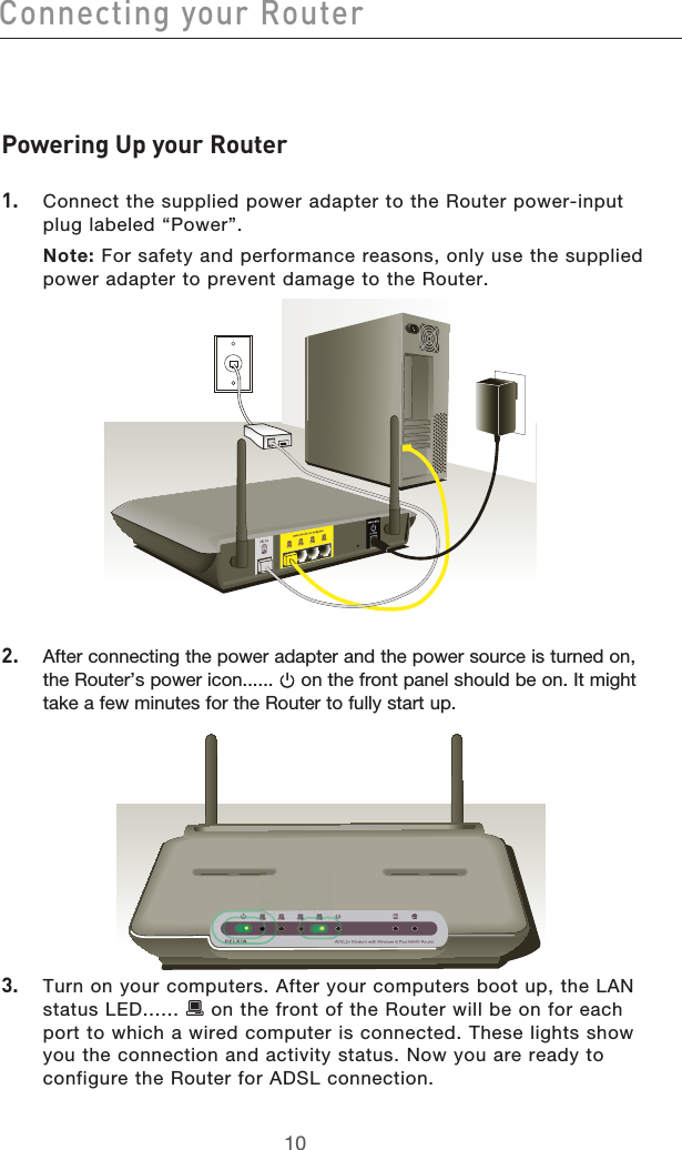
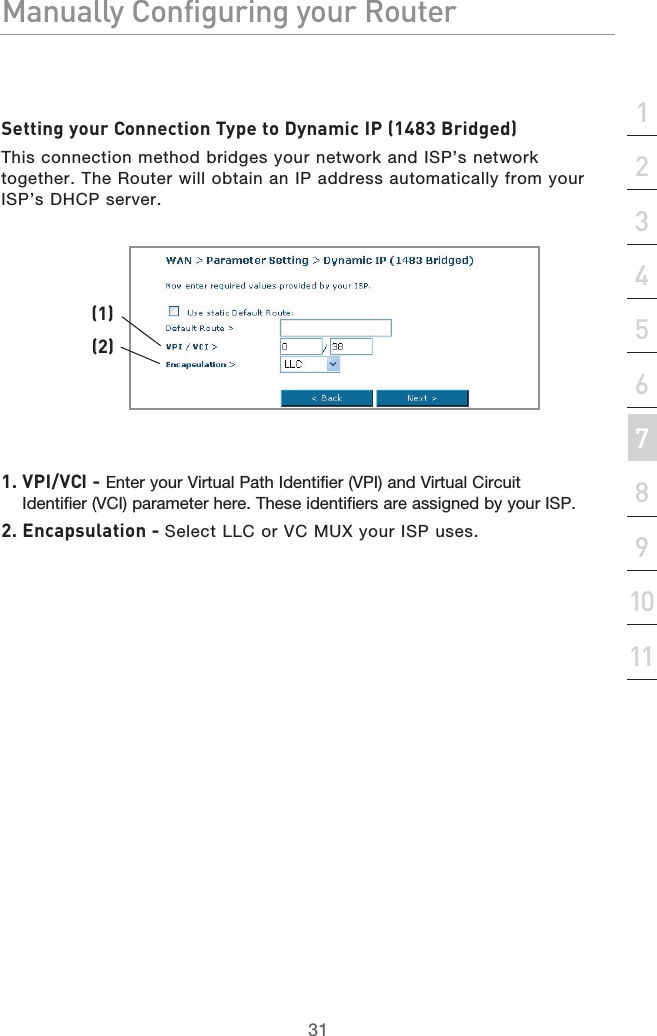
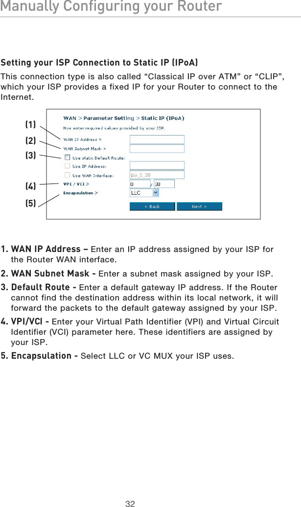
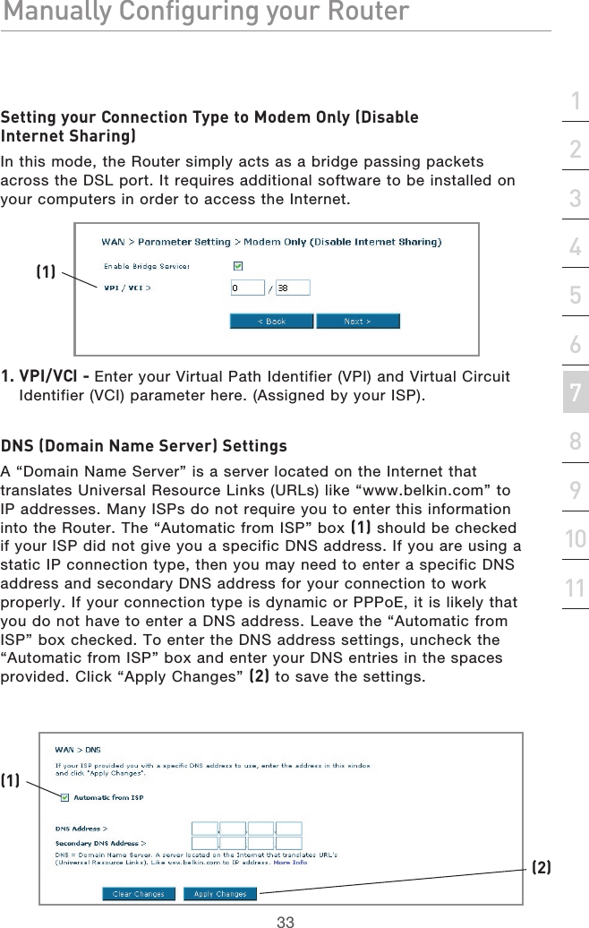
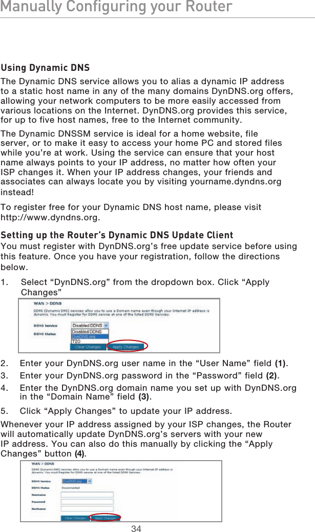
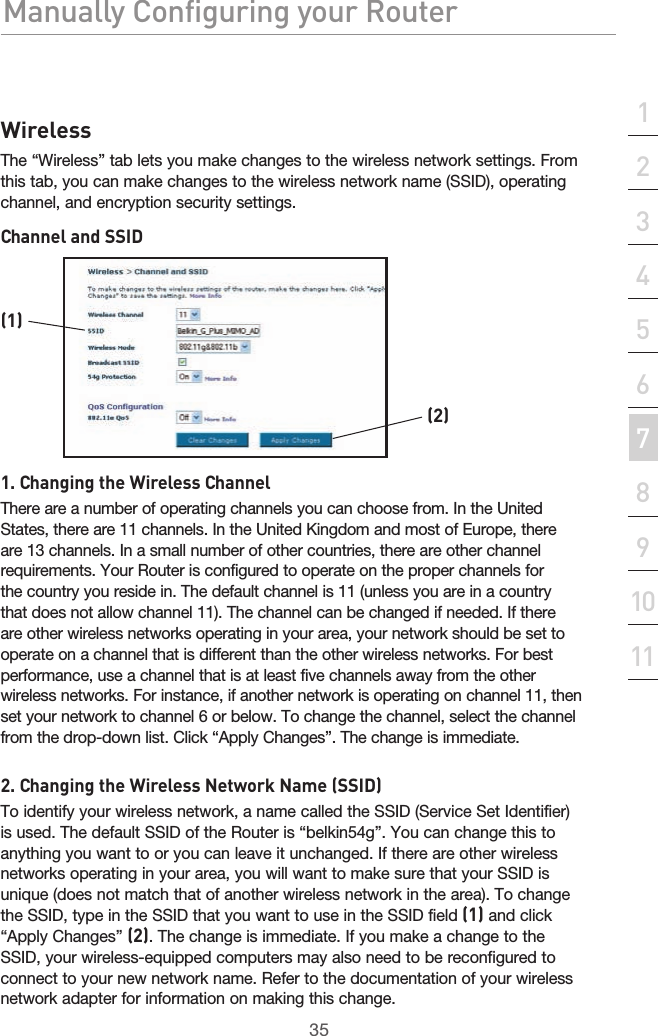
Manual 1