Belkin F5D9630-4V2 ADSL2+ Modem with Wireless G Plus MIMO Router User Manual
Belkin International, Inc. ADSL2+ Modem with Wireless G Plus MIMO Router Users Manual
UserManual.wiki
>
Belkin
>
F5D9630 4V2 User Manual
Users Manual
Navigation menu
Upload a User Manual
Namespaces
Wiki Guide
HTML
PDF
Info
Views
User Manual
Discussion / Help
Navigation
![[insert Belkin logo] ADSL2+ Modem with Wireless G Plus MIMO Router .bj.kb;kgkvjf Network your computers and share your ADSL Internet access User Manual F5D9630-4 Table of Contents 1 Introduction . . . . . . . . . . . . . . . . . . . . . . . . . . . . . . . . . . . . . . . .1 Benefits of a Home Network . . . . . . . . . . . . . . . . . . . . . . . . . .1 Advantages of a Belkin Wireless Network . . . . . . . . . . . . . . . .1 2 Make Sure You Have the Following . . . . . . . . . . . . . . . . . . . . . . .2 Package Contents . . . . . . . . . . . . . . . . . . . . . . . . . . . . . . . . . .2 System Requirements . . . . . . . . . . . . . . . . . . . . . . . . . . . . . . .2 Internet Connection Settings . . . . . . . . . . . . . . . . . . . . . . . . . .2 3 Knowing your Router . . . . . . . . . . . . . . . . . . . . . . . . . . . . . . . . .3 4 Connecting your Router . . . . . . . . . . . . . . . . . . . . . . . . . . . . . . .6 Positioning your Router . . . . . . . . . . . . . . . . . . . . . . . . . . . . . .6 Connecting your Computers . . . . . . . . . . . . . . . . . . . . . . . . . .7 Connecting your ADSL Line . . . . . . . . . . . . . . . . . . . . . . . . . . .8 Powering Up your Router. . . . . . . . . . . . . . . . . . . . . . . . . . . .10 5 Setting Up your Computers . . . . . . . . . . . . . . . . . . . . . . . . . . .11 Manually Configuring Network Adapters . . . . . . . . . . . . . . . .12 Recommended Web Browser Settings. . . . . . . . . . . . . . . . . .17 6 Configuring your Router with the Setup Wizard . . . . . . . . . . .19 Running the Setup Wizard . . . . . . . . . . . . . . . . . . . . . . . . . . .19 Connecting to the Wireless LAN . . . . . . . . . . . . . . . . . . . . . 20 7 Manually Configuring Your Router . . . . . . . . . . . . . . . . . . . . . .23 Understanding the Web-Based User Interface. . . . . . . . . . . .23 Changing LAN Settings . . . . . . . . . . . . . . . . . . . . . . . . . . . . .25 Internet WAN . . . . . . . . . . . . . . . . . . . . . . . . . . . . . . . . . . . . .28 Wireless . . . . . . . . . . . . . . . . . . . . . . . . . . . . . . . . . . . . . . . . .34 Firewall. . . . . . . . . . . . . . . . . . . . . . . . . . . . . . . . . . . . . . . . . .52](https://usermanual.wiki/Belkin/F5D9630-4V2/User-Guide-729994-Page-1.png)
![• No other DHCP server on your local network assigning IP addresses to computers and devices Internet Connection Settings Please collect the following information from your Internet Service Provider (ISP) before setting up the ADSL Modem Wireless G Router. • Internet connection protocol: _________ (PPPoE, PPPoA, Dynamic IP, Static IP) • Multiplexing method or Encapsulation: __________ (LLC or VC MUX) • Virtual circuit: VPI (Virtual Path Identifier) __________ (a number between 0 and 255) • VCI (Virtual Channel Identifier) __________ (a number between 1 and 65535) • For PPPoE and PPPoA users: ADSL account user name _____________ and password _______________ • For static IP users: IP Address ___ . ___ . ___ . ___ Subnet Mask ___ . ___ . ___ . ___ Default Gateway Server ___ . ___ . ___ . • IP address for Domain Name Server ___ . ___ . ___ . ___ (If given by your ISP) Note: See Appendix C in this User Manual for some common DSL Internet setting parameters. If you are not sure, please contact your ISP. Knowing your Router The Router is designed to be placed on a desktop. All of the cables exit from the rear of the Router for better organization and utility. The LED indicators are easily visible on the front of the Router to provide you with information about network activity and status. [replace the following section with the same section from F5D7633-4 see P74730uk] Front Panel [Insert: 9630-4 front image w/ arrows to LEDs] 1) [Insert: icon] Power LED 2) [Insert: icon] LAN Status LED (1-4) 3) [Insert: icon] Wireless LAN (WLAN) Status LED 4) [Insert: icon] ADSL LED 5) [Insert: icon] Internet 1. Power LED When you apply power to the Router or restart it, a short period of time elapses while the Router boots up. When the Router has completely booted up, the Power LED becomes a GREEN light, indicating the Router is ready for use. OFF Router is off Green Router is on Insert: Power Icon Red Router failed to start 2. LAN Status LEDs These LAN Status LEDs are labeled 1–4 and correspond to the numbered ports on the rear of the Router. When a computer is properly connected to one of the LAN ports on the rear of the Router, the LED will light. Solid GREEN means a computer or a network-enabled device is connected. When information is being](https://usermanual.wiki/Belkin/F5D9630-4V2/User-Guide-729994-Page-3.png)
![sent over the port, the LED blinks rapidly. ORANGE indicates a 10Base-T connection. OFF No device is connected Orange Ethernet link is up and 10Base-T device connected Orange—blinking When 10Base-T device transmitting or receiving data Green Ethernet link is up and 100Base-T connected Insert LAN Icon Green—blinking When 100Base-T device transmitting or receiving data 3. WLAN Status LED The WLAN Status LED is solid GREEN when you enable the wireless LAN function. It flashes when the Router is transmitting or receiving data wirelessly. OFF WLAN is off Green WLAN is up and connected Insert WLAN Icon Green—blinking When transmitting or receiving data 4. ADSL LED The ADSL LED flashes GREEN during negotiation with your ISP. It stays GREEN when the Router is connected properly to your ADSL service. OFF No ADSL connection Green – blinking Negotiating connection Insert ADSL Icon Green ADSL link is up and connected 5. Internet LED The Internet LED shows you when the Router is connected to the Internet. When the LED is OFF, the Router is NOT connected to the Internet. When the LED is solid GREEN, the Router is connected to the Internet. When the LED is blinking, the Router is transmitting or receiving data from the Internet. OFF No Internet connection Green Connected to the Internet Green – blinking When transmitting or receiving data Insert Internet Icon Red Failed to get IP Back Panel [Insert: 9630-4 back image w/ arrows to ports] 6) [Insert: icon] DSL Line](https://usermanual.wiki/Belkin/F5D9630-4V2/User-Guide-729994-Page-4.png)
![7) [Insert: icon] Ethernet Ports (4–1) 8) [Insert: icon] Reset Button 9) [Insert: icon] Power Plug 6. DSL Line This port is for connection to your ADSL line. Connect your ADSL line to this port. 7. Ethernet Ports The Ethernet ports are RJ45, 10/100 auto-negotiation. The ports are labeled 1 through 4. These ports correspond to the numbered LEDs on the front of the Router. Connect your network-enabled computers or any networking devices to one of these ports. 8. Reset Button The “Reset” button is used in rare cases when the Router may function improperly. Resetting the Router will restore the Router’s normal operation while maintaining the programmed settings. You can also restore the factory default settings by using the Reset button. Use the restore option in instances where you may have forgotten your custom password. a. Resetting the Router Push and hold the Reset button for one second then release it. When the Power/Ready light becomes solid again, the reset is complete. b. Restoring the Factory Defaults Press and hold the Reset button for five seconds then release it. When the Power/Ready light becomes solid again, the restore is complete. 9. Power Plug Connect the included 15V DC power supply to this inlet. Using the wrong type of power adapter may cause damage to your Router. Connecting your Router Positioning your Router Your wireless connection will be stronger the closer your computer is to your Router. Typical indoor operating range for your wireless devices is between 100 and 200 feet. In the same way, your wireless connection and performance will degrade somewhat as the distance between your Router connected devices increases. This may or may not be noticeable to you. As you move farther from your Router, connection speed may decrease. Factors that can weaken signals simply by getting in the way of your network’s radio waves are metal appliances, or obstructions, and walls. Please see “Appendix B: Important Factors for Placement and Setup” in this User Manual for more guidelines. If you have concerns about your network’s performance that might be related to range or obstruction factors, try moving the computer to](https://usermanual.wiki/Belkin/F5D9630-4V2/User-Guide-729994-Page-5.png)
![a position between five and 10 feet from the Router, in order to see if distance is the problem. If difficulties persist even at close range, please see the Troubleshooting section for solutions. Connecting your Computers 1. Power off your computers and networking equipment. 2. Connect your computer to one of the YELLOW RJ45 ports on the rear of the Router labeled “connections to your computers” by using an Ethernet networking cable (one Ethernet network cable is supplied). [insert 9630-4 rear illustration. Can use the same image from F5D7633-4] Connecting your ADSL Line Connection for the Router to the ADSL line varies by country and region. Typically it involves a microfilter or a microfilter with built-in splitter to allow simultaneous use of ADSL service and telephone service on the same telephone line. Please read the following steps carefully and select appropriate method. 1. If your telephone service and ADSL service are on the same telephone line, ADSL microfilters are needed for each telephone and device, such as answering machine, fax machine, and caller ID display. Additional splitters may be used to separate telephone lines for telephone and the Router. Note: Do not connect the ADSL microfilter between the wall jack and the Router—this will prevent ADSL service from reaching the modem. 2. If your telephone service and ADSL service are on the same telephone line and you are using an ADSL microfilter with built-in splitter, connect the splitter to the telephone wall jack providing ADSL service. Then, connect the telephone cord from the ADSL microfilter RJ11 port generally labeled “DSL” to the gray RJ11 port labeled “DSL line” on the back of your Router. Connect telephony device to the other port on the ADSL splitter commonly labeled “Phone”. An additional ADSL microfilter is needed for another telephone and device on the same line. [insert 9630-4 rear illustration. Can use the same image from F5D7633-4] Note: One RJ11 telephone cord is supplied. When inserting an RJ11 plug, be sure the tab on the plug clicks into position to ensure that it is properly seated. 3. If you have a dedicated ADSL service telephone line with an RJ11 wall jack, simply connect a telephone cord from the wall jack to the gray RJ11 port labeled “DSL line” on the back of your Router. 4. If you have an RJ45 wall jack for your ADSL service, connect an RJ45-to-RJ11 converter to the wall jack. Then connect one end of a telephone cord to the converter and the other end to the gray RJ11 port labeled “DSL line” on the back of your Router. Note: ADSL microfilter may or may not be provided depending on your country. Powering Up your Router 1. Connect the supplied power adapter to the Router power-input plug labeled “Power”. Note: For safety and performance reasons, only use the supplied power adapter to prevent damage to the Router. [insert 9630-4 rear illustration. Can use the same image from F5D7633-4] 2. After connecting the power adapter and the power source is turned on, the Router’s power icon on the front panel should be on. It might take a few minutes for the Router to fully start up.](https://usermanual.wiki/Belkin/F5D9630-4V2/User-Guide-729994-Page-6.png)
![[insert 9630-4 front illustration. Can use the same image from F5D7633-4. If the product name is clearly visible, correct it to ADSL2+ Modem with Wireless G Plus MIMO Router] 3. Turn on your computers. After your computers boot up, the LAN status LED on the front of the Router will be on for each port to which a wired computer is connected. These lights show you the connection and activity status. Now you are ready to configure the Router for ADSL connection. In order for your computer to properly communicate with your Router, you will need to change your computer’s “TCP/IP Ethernet” settings to “Obtain an IP address automatically/Using DHCP”. This is normally the default setting in most home computers. You can set up the computer that is connected to the ADSL modem FIRST using these steps. You can also use these steps to add computers to your Router after the Router has been set up to connect to the Internet. Manually Configuring Network Adapters in Windows XP, 2000, or NT 1. Click “Start”, “Settings”, then “Control Panel”. 2. Double-click on the “Network and dial-up connections” icon (Windows 2000) or the “Network” icon (Windows XP). 3. Right-click on the “Local Area Connection” associated with your network adapter and select “Properties” from the drop-down menu. 4. In the “Local Area Connection Properties” window, click “Internet Protocol (TCP/IP)” and click the “Properties” button. The following screen will appear: [Use existing screenshot] (1) (2) (3) 5. If “Use the following IP address” (2) is selected, your Router will need to be set up for a static IP connection type. Write the address information the table below. You will need to enter this information into the Router. [Use existing screenshot] 6. If not already selected, select “Obtain an IP address automatically” (1) and “Obtain DNS server address automatically” (3). Click “OK”. Your network adapter(s) are now configured for use with the Router. Manually Configuring Network Adapters in Windows 98SE or Me 1. Right-click on “My Network Neighborhood” and select “Properties” from the drop-down menu. 2. Select “TCP/IP -> settings” for your installed network adapter. You will see the following window. [Use existing screenshot] (1) (2) (3) 3. If “Specify an IP address” is selected, your Router will need to be set up for a static IP connection type. Write the address information in the table below. You will need to enter this information into the Router. [Use existing screenshot] 4. Write the IP address and subnet mask from the “IP Address” tab (3). 5. Click the “Gateway” tab (2). Write the gateway address down in the chart. 6. Click the “DNS Configuration” tab (1). Write the DNS address(es) in the chart. 7. If not already selected, select “Obtain an IP address automatically” on the IP address tab. Click “OK”. 8. You will also need to delete the Gateway address from the Gateway tab and DNS Configuration entries in order to properly be configured for connection to the Belkin router. Restart the computer. When the computer restarts, your network adapter(s) are now configured for use with the Router. Set up the computer that is connected to the cable or DSL modem by FIRST using these steps. You can also use these steps to add computers to your Router after the Router has been set up to connect](https://usermanual.wiki/Belkin/F5D9630-4V2/User-Guide-729994-Page-7.png)
![to the Internet. Manually Configuring Network Adapters in Mac OS up to 9.x In order for your computer to properly communicate with your Router, you will need to change your Mac computer’s TCP/IP settings to DHCP. 1. Pull down the Apple menu. Select “Control Panels” and select “TCP/IP”. 2. You will see the TCP/IP control panel. Select “Ethernet Built-In” or “Ethernet” in the “Connect via:” drop-down menu (1). [Use existing screenshot] (1) (2) 3. Next to “Configure” (2), if “Manually” is selected, your Router will need to be set up for a static IP connection type. Write the address information in the table below. You will need to enter this information into the Router. [Use existing screenshot] 4. If not already set, at “Configure:”, choose “Using DHCP Server”. This will tell the computer to obtain an IP address from the Router. [Use existing screenshot] 5. Close the window. If you made any changes, the following window will appear. Click “Save”. Restart the computer. When the computer restarts, your network settings are now configured for use with the Router. [Use existing screenshot] Manually Configuring Network Adapters in Mac OS X 1. Click on the “System Preferences” icon. [Use existing screenshot] 2. Select “Network” (1) from the “System Preferences” menu. [Use existing screenshot] (1) 3. Select “Built-in Ethernet” (2) next to “Show” in the Network menu. [Use existing screenshot] (2) (3) (4) 4. Select the “TCP/IP” tab (3). Next to “Configure” (4), you should see “Manually” or “Using DHCP”. If you do not, check the PPPoE tab (5) to make sure that “Connect using PPPoE” is NOT selected. If it is, you will need to configure your Router for a PPPoE connection type using your user name and password. 5. If “Manually” is selected, your Router will need to be set up for a static IP connection type. Write the address information in the table below. You will need to enter this information into the Router. [Use existing screenshot] 6. If not already selected, select “Using DHCP” next to “Configure” (4), then click “Apply Now”. Your network adapter(s) are now configured for use with the Router.](https://usermanual.wiki/Belkin/F5D9630-4V2/User-Guide-729994-Page-8.png)
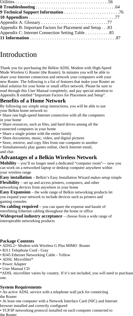
![Recommended Web Browser Settings In most cases, you will not need to make any changes to your web browser’s settings. If you are having trouble accessing the Internet or the advanced web-based user interface, then change your browser’s settings to the recommended settings in this section. Internet Explorer 4.0 or Higher [insert updated screenshots] IE6_Internet_Options.jpg 1. Start your web browser. Select “Tools” then “Internet Options”. 2. In the “Internet Options” screen, there are three selections: “Never dial a connection”, “Dial whenever a network connection is not present”, and “Always dial my default connection”. If you can make a selection, select “Never dial a connection”. If you cannot make a selection, go to the next step. IE6_Internet_Options_Connections.jpg](https://usermanual.wiki/Belkin/F5D9630-4V2/User-Guide-729994-Page-9.png)
![Netscape Navigator 4.0 or Higher 1. Start Netscape. Click on “Edit” then “Preferences”. 2. In the “Preferences” window, click on “Advanced” then select “Proxies”. In the “Proxies” window, select “Direct connection to the Internet”. [Use existing screenshot] Running the Setup Wizard 1. You can access the web-based management user interface of the Router using the Internet browser on a computer connected to the Router. Type “192.168.2.1” (do not type in anything else such as “http://” or “www”) in your browser’s address bar. Then press the “Enter” key. [insert 9630_IP_Address.tif] Note: It is strongly recommended that you use a computer physically connected to the Router with an RJ45 cable for initial setup. Using a wirelessly connected computer for initial setup is not recommended. 2. The following screen will appear in your browser to prompt you to log in. The Router ships with no password entered. In the login screen, leave the password blank and click the “Submit” button to log in. [insert 9630_Login.tif]](https://usermanual.wiki/Belkin/F5D9630-4V2/User-Guide-729994-Page-11.png)
![Note: It is strongly recommended that you change the password to your own for increased security. Please read the following section, entitled “Manually Configuring your Router”, for details on how to change your password and to reference other security features. Understanding the Web-Based User Interface The home page shows you a quick view of the Router’s status and settings. All advanced setup pages can be reached from this page. [insert 9630_Home.tif] (1) (9) (2) (5) (4) (3) (10) (6) (8) (7) 1. Quick-Navigation Links](https://usermanual.wiki/Belkin/F5D9630-4V2/User-Guide-729994-Page-12.png)
![You can go directly to any of the Router’s UI pages by clicking directly on these links. The links are divided into logical categories and grouped by tabs to make finding a particular setting easier to find. Clicking on the header of each tab will show you a short description of the tab’s function. 2. Home Button The “Home” button is available in every page of the UI. Pressing this button will take you back to the home page. 3. Help Button The “Help” button gives you access to the Router’s help pages. Help is also available on many pages by clicking “more info” next to certain sections of each page. 4. Login/Logout Button This button enables you to log in and out of the Router with the press of one button. When you are logged into the Router, this button will change to read “Logout”. Logging into the Router will take you to a separate login page where you will need to enter a password. When you are logged into the Router, you can make changes to the settings. When you are finished making changes, you can log out of the Router by clicking the “Logout” button. For more information about logging into the Router, see the section called “Logging into the Router”. 5. Internet Status Indicator This indicator is visible in all pages of the Router, showing the connection status of the Router. When the indicator says “connection OK” in GREEN, the Router is connected to the Internet. When the Router is not connected to the Internet, the indicator will read “no connection” in RED. The indicator is automatically updated when you make changes to the settings of the Router. 6. LAN Settings Shows you the settings of the Local Area Network (LAN) side of the Router. Changes can be made to the settings by clicking the “LAN” “Quick Navigation” link on the left side of the screen. 7. Features Shows the status of the Router’s UPnP, NAT, and firewall features. Changes can be made to the settings by clicking on any one of the links or by clicking the “Quick Navigation” links on the left side of the screen. 8. Internet Settings Shows the settings of the Internet/WAN side of the Router that connects to the Internet. Changes to any of these settings can be made by clicking on the “Internet/WAN” “Quick Navigation” link on the left side of the screen. 9. Version Info Shows the firmware version, boot-code version, hardware version, and serial number of the Router. 10. Page Name The page you are on can be identified by this name. This manual will sometimes refer to pages by name. For instance, “LAN > LAN Settings” refers to the “LAN Settings” page. Changing LAN Settings All settings for the internal LAN setup of the Router can be viewed and changed here. Clicking on the header of the LAN tab (1) will take you to the LAN tab’s header page. A quick description of the functions can be found here. To view the settings or make changes to any of the LAN settings, click on “LAN Settings” (2) or to view the list of connected computers, click on “DHCP Client List” (3). [insert 963_LAN.tif]](https://usermanual.wiki/Belkin/F5D9630-4V2/User-Guide-729994-Page-13.png)
![(1) (2) (3) LAN Settings [insert 9630_LAN_Settings.tif] (1) (2) (3) (4) (5) (6) 1. IP Address The “IP address” is the internal IP address of the Router. The default IP address is “192.168.2.1”. To access the setup interface, type this IP address into the address bar of your browser. This address can be changed if needed. To change the IP address, type in the new IP address and click “Apply](https://usermanual.wiki/Belkin/F5D9630-4V2/User-Guide-729994-Page-14.png)
![Changes”. The IP address you choose should be a non-routable IP. Examples of a non-routable IP are: 192.168.x.x (where x is anything between 0 and 255) 10.x.x.x (where x is anything between 0 and 255) 2. Subnet Mask There is no need to change the subnet mask as the router will automatically adjust the length based on the IP address type. 3. DHCP Server The DHCP server function makes setting up a network very easy by assigning IP addresses to each computer on the network automatically. The default setting is “On”. The DHCP server can be turned OFF if necessary, however, in order to do so you must manually set a static IP address for each computer on your network. To turn off the DHCP server, select “Off” and click “Apply Changes”. 4. IP Pool The IP Pool is the range of IP addresses set aside for dynamic assignment to the computers on your network. The default is 2–100 (99 computers). If you want to change this number, you can do so by entering a new starting and ending IP address and clicking on “Apply Changes”. The DHCP server can assign 100 IP addresses automatically. This means that you cannot specify an IP address pool larger than 100 computers. For example, starting at 50 means you have to end at 150 or lower so as not to exceed the 100-client limit. The starting IP address must be lower in number than the ending IP address. 5. Lease Time Lease time is the length of time the DHCP server will reserve the IP address for each computer. We recommend that you leave the lease time set to “Forever”. The default setting is “Forever”, meaning that any time a computer is assigned an IP address by the DHCP server, the IP address will not change for that particular computer. Setting lease times for shorter intervals, such as one day or one hour, frees IP addresses after the specified period of time. This also means that a particular computer’s IP address may change over time. If you have set any of the other advanced features of the Router, such as DMZ or client IP filters, these are dependent on the IP address. For this reason, you will not want the IP address to change. 6. Local Domain Name The default setting is “Belkin”. You can set a local domain name (network name) for your network. There is no need to change this setting unless you have a specific advanced need to do so. You can name the network anything you want such as “MY NETWORK”. DHCP Client List You can view a list of the computers (known as clients), which are connected to your network. You are able to view the IP address (1) of the computer, the host name (2) (if the computer has been assigned one), and the MAC address (3) of the computer’s Network Interface Card (NIC). Pressing the “Refresh” (4) button will update the list. If there have been any changes, the list will be updated. [insert 9630_DHCP_Client.tif]](https://usermanual.wiki/Belkin/F5D9630-4V2/User-Guide-729994-Page-15.png)
![(1) (2) (3) (4) Internet WAN The “Internet WAN” tab is where you will set up your Router to connect to your Internet Service Provider. The Router is capable of connecting to virtually any ADSL Service Provider’s system provided you have correctly configured the Router’s settings for your ISP’s connection type. Your connection settings are provided to you by your ISP. To configure the Router with the settings that your ISP gave you, click “Connection Type” (1) on the left side of the screen. Select the connection type you use. If your ISP gave you DNS settings, clicking “DNS” (2) allows you to enter DNS address entries for ISPs that require specific settings. When you have finished making settings, the “Internet Status” indicator will read “Connection OK” if your Router is set up properly. [insert 9630_Internet_WAN.tif] (1) (2)](https://usermanual.wiki/Belkin/F5D9630-4V2/User-Guide-729994-Page-16.png)
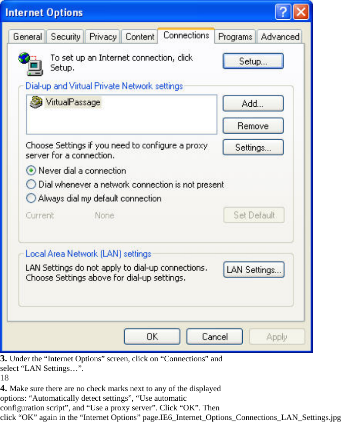
![Connection Type From the “Connection Type” page, you can select one of these five connection types based on the instruction provided by your ISP: • PPPoE • PPPoA • Dynamic IP (1483 Bridged) • Static IP (IPOA) • Modem Only (Disable Internet Sharing) Note: See Appendix C in this User Manual for some common DSL Internet setting parameters. If you are not sure, please contact your ISP. Select the type of connection you use by clicking the radio button (1) next to your connection type and then clicking “Next” (2). [insert 9630_Connection_Type.tif] (1) (2) Setting your ISP Connection Type to PPPoE or PPPoA PPPoE (Point-to-Point Protocol over Ethernet) is the standard method of connecting networked devices. It requires a user name and password to access the network of your ISP for connecting to the Internet. PPPoA (PPP over ATM) is similar to PPPoE, but is mostly implemented in the UK. Select PPPoE or PPPoA and click “Next”. Then enter the information provided by your ISP, and click “Apply Changes” to activate your settings. [insert 9630_PPPoE.tif]](https://usermanual.wiki/Belkin/F5D9630-4V2/User-Guide-729994-Page-17.png)
![Setting your Connection Type to Dynamic IP (1483 Bridged) This connection method bridges your network and ISP’s network together. The Router will obtain an IP address automatically from your ISP’s DHCP server. [insert 9630_Dynamic_IP.tif] (1) (2) 1. VPI/VCI - Enter your Virtual Path Identifier (VPI) and Virtual Circuit Identifier (VCI) parameter here. These identifiers are assigned by your ISP. 2. Encapsulation - Select LLC or VC MUX your ISP uses. Setting your ISP Connection to Static IP (IPoA) This connection type is also called “Classical IP over ATM” or “CLIP”, which your ISP provides a fixed IP for your Router to connect to the Internet.](https://usermanual.wiki/Belkin/F5D9630-4V2/User-Guide-729994-Page-19.png)
![[insert 9630_IPoA.tif] (1) (2) (3) (4) (5) 1. WAN IP Address – Enter an IP address assigned by your ISP for the Router WAN interface. 2. WAN Subnet Mask - Enter a subnet mask assigned by your ISP. 3. Default Route - Enter a default gateway IP address. If the Router cannot find the destination address within its local network, it will forward the packets to the default gateway assigned by your ISP. 4. VPI/VCI - Enter your Virtual Path Identifier (VPI) and Virtual Circuit Identifier (VCI) parameter here. These identifiers are assigned by your ISP. 5. Encapsulation - Select LLC or VC MUX your ISP uses. Setting your Connection Type to Modem Only (Disable Internet Sharing) In this mode, the Router simply acts as a bridge passing packets across the DSL port. It requires additional software to be installed on your computers in order to access the Internet. [insert 9630_Modem_Only.tif]](https://usermanual.wiki/Belkin/F5D9630-4V2/User-Guide-729994-Page-20.png)
![(1) 1. VPI/VCI - Enter your Virtual Path Identifier (VPI) and Virtual Circuit Identifier (VCI) parameter here. (Assigned by your ISP). DNS (Domain Name Server) Settings A “Domain Name Server” is a server located on the Internet that translates Universal Resource Links (URLs) like “www.belkin.com” to IP addresses. Many ISPs do not require you to enter this information into the Router. The “Automatic from ISP” box (1) should be checked if your ISP did not give you a specific DNS address. If you are using a static IP connection type, then you may need to enter a specific DNS address and secondary DNS address for your connection to work properly. If your connection type is dynamic or PPPoE, it is likely that you do not have to enter a DNS address. Leave the “Automatic from ISP” box checked. To enter the DNS address settings, uncheck the “Automatic from ISP” box and enter your DNS entries in the spaces provided. Click “Apply Changes” (2) to save the settings. [insert 9630_DNS.tif]](https://usermanual.wiki/Belkin/F5D9630-4V2/User-Guide-729994-Page-21.png)
![(2) (1) [insert the following section from P74304-C F5D8230-4 v2 manual] Using Dynamic DNS The Dynamic DNS service allows you to alias a dynamic IP address to a static host name in any of the many domains DynDNS.org offers, allowing your network computers to be more easily accessed from various locations on the Internet. DynDNS.org provides this service, for up to five host names, free to the Internet community. The Dynamic DNSSM service is ideal for a home website, file server, or to make it easy to access your home PC and stored files while you’re at work. Using the service can ensure that your host name always points to your IP address, no matter how often your ISP changes it. When your IP address changes, your friends and associates can always locate you by visiting yourname.dyndns.org instead! To register free for your Dynamic DNS host name, please visit http://www.dyndns.org. Setting up the Router’s Dynamic DNS Update Client You must register with DynDNS.org’s free update service before using this feature. Once you have your registration, follow the directions below. 1. Select “DynDNS.org” from the dropdown box. Click “Apply Changes” [insert 9630_DDNS.tif] 2. Enter your DynDNS.org user name in the “User Name” field (1). 3. Enter your DynDNS.org password in the “Password” field (2). 4. Enter the DynDNS.org domain name you set up with DynDNS.org in the “Domain Name” field (3). 5. Click “Apply Changes” to update your IP address.](https://usermanual.wiki/Belkin/F5D9630-4V2/User-Guide-729994-Page-22.png)
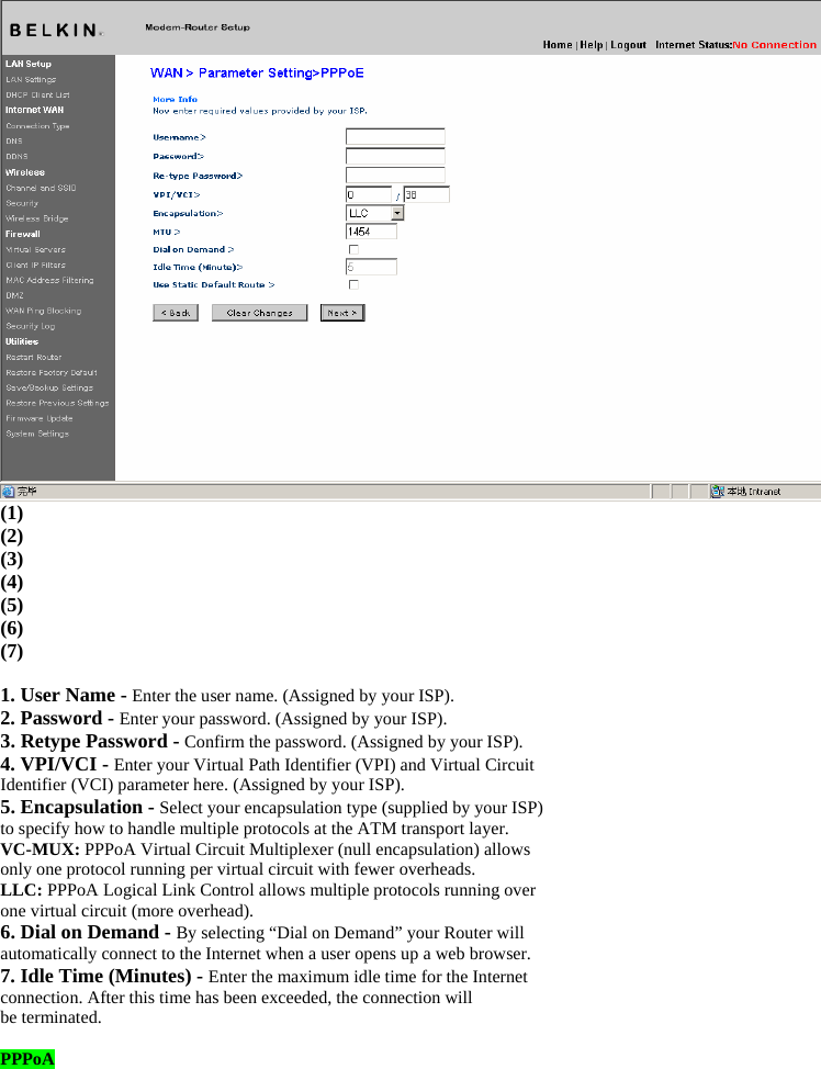
![Whenever your IP address assigned by your ISP changes, the Router will automatically update DynDNS.org’s servers with your new IP address. You can also do this manually by clicking the “Apply Changes” button (4). [insert 9630_DDNS_DynDNS.tif] (1) (2) (3) (4) Wireless The “Wireless” tab lets you make changes to the wireless network settings. From this tab, you can make changes to the wireless network name (SSID), operating channel, and encryption security settings. Channel and SSID [insert 9630_Channel_SSID.tif]](https://usermanual.wiki/Belkin/F5D9630-4V2/User-Guide-729994-Page-23.png)
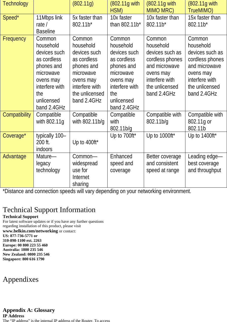
![This option gives the best performance but will not allow 802.11b clients to connect. 5. Protected Mode Switch As part of the 802.11g specification, Protected mode ensures proper operation of 802.11g clients and access points when there is heavy 802.11b traffic in the operating environment. When Protected mode is ON, 802.11g scans for other wireless network traffic before it transmits data. Therefore, using this mode in environments with HEAVY 802.11b traffic or interference achieves best performance results. If you are in an environment with very little—or no—wireless network traffic, your best performance will be achieved with Protected mode OFF. Encryption/Security Securing your Wi-Fi Network Here are a few different ways you can maximize the security of your wireless network and protect your data from prying eyes and ears. This section is intended for the home, home office, and small office user. At the time of this User Manual’s publication, there are four encryption methods available. [Update with the following chart] Name 64-Bit Wired Equivalent Privacy 128-Bit Wired Equivalent Privacy Wi-Fi Protected Access-TKIP Wi-Fi Protected Access 2 Acronym 64-bit WEP 128-bit WEP WPA-TKIP/AES (or just WPA) WPA2-AES (or just WPA2)Security Good Better Best Best Features Static keys Static keys Dynamic key encryption and mutual authentication Dynamic key encryption and mutual authentication Encryption keys based on RC4 algorithm (typically 40-bit keys) More secure than 64-bit WEP using a key length of 104 bits plus 24 additional bits of system-generated data TKIP (Temporal Key Integrity Protocol) added so that keys are rotated and encryption is strengthened AES (Advanced Encryption Standard) does not cause any throughput loss . WEP (Wired Equivalent Privacy) WEP is a common protocol that adds security to all Wi-Fi-compliant wireless products. WEP was designed to give wireless networks the equivalent level of privacy protection as a comparable wired network. 64-Bit WEP 64-bit WEP was first introduced with 64-bit encryption, which includes a key length of 40 bits plus 24 additional bits of system-generated data (64 bits total). Some hardware manufacturers refer to 64-bit as 40-bit encryption. Shortly after the technology was introduced, researchers found that 64-bit encryption was too easy to decode. 128-Bit WEP As a result of 64-bit WEP’s potential security weaknesses, 128Bit WEP was developed as a more secure method of encryption. 128-bit encryption includes a key length of 104 bits plus 24 additional bits of system-generated data (128 bits total). Some hardware manufacturers refer to 128-bit as 104-bit encryption. Most of the new wireless equipment in the market today supports both 64-bit and 128-bit WEP encryption, but you might have older equipment that only supports 64-bit WEP. All Belkin wireless products will support both 64-bit and 128-bit WEP. Encryption Keys After selecting either the “64-bit” or “128-bit WEP” encryption mode, it is critical that you generate an encryption key. If the encryption key is not consistent throughout the entire wireless network, your wireless networking devices will be unable to communicate with one another on your network and you will not be able to successfully communicate within your network. You can enter your key by typing in the hex key manually, or you can type in a passphrase in the “Passphrase” field and click “Generate”](https://usermanual.wiki/Belkin/F5D9630-4V2/User-Guide-729994-Page-25.png)
![to create a key. A hex (hexadecimal) key is a mixture of numbers and letters from A–F and 0–9. For 64-bit WEP, you need to enter 10 hex characters. For 128-bit WEP, you need to enter 26 hex characters. The WEP passphrase is NOT the same as a WEP key. Your wireless card uses this passphrase to generate your WEP keys, but different hardware manufacturers might have different methods for generating the keys. If you have equipment from multiple vendors in your network, you can use the hex WEP key from your Router or access point and enter it manually into the hex WEP key table in your wireless card’s configuration screen. Using a Hexadecimal Key A hexadecimal key is a mixture of numbers and letters from A–F and 0–9. 64-bit keys are five two-digit numbers. 128-bit keys are 13 two-digit Characters. For instance: AF 0F 4B C3 D4 = 64-bit key C3 03 0F AF 0F 4B B2 C3 D4 4B C3 D4 E7 = 128-bit key In the boxes below, make up your key by writing in two characters between A–F and 0–9 in each box. You will use this key to program the encryption settings on your Router and your wireless computers. [Use current image] Note to Mac users: Original Apple AirPort® products support 64-bit encryption only. Apple AirPort 2 products can support 64-bit or 128-bit encryption. Please check your product to see which version you are using. If you cannot configure your network with 128-bit encryption, try 64-bit encryption. WPA (Wi-Fi Protected Access) WPA (Wi-Fi Protected Access) is a new Wi-Fi standard that was designed to improve upon the security features of WEP. To use WPA security, the drivers and software of your wireless equipment must be upgraded to support WPA. These updates will be found on the wireless vendors’ websites. There are two types of WPA security: WPA-Personal (PSK) and WPA-Enterprise (RADIUS) WPA-Personal (PSK) This method uses what is known as a Pre-Shared key as the Network key. A Network key is basically a password that is between eight and 63 characters long. It can be a combination of letters, numbers, or characters. Each client uses the same Network key to access the network. Typically, this is the mode that will be used in a home environment. WPA-Enterprise (RADIUS) With this system, a radius server distributes the Network key to the clients automatically. This is typically found in a business environment. For a list of Belkin wireless products that support WPA, please visit our website at www.belkin.com/networking. WPA2 (WiFi Protected Access) WPA2 is the second generation of WPA based 802.11i standard. It offers higher level of wireless security by combining advanced network authentication and stronger AES encryption method. Like WPA security, WPA2 is available in both WPA2-Personal (PSK) mode and WPA2-Enterprise (RADIUS) mode. Typically, WPA2-Personal (PSK) is the mode that will be used in a home environment, while WPA-Enterprise (RADIUS) is implemented in a business environment where an external radius server distributes the network key to the clients automatically. Sharing the Same Network Keys Most Wi-Fi products ship with security turned off. So once you have your network working, you need to activate WEP or WPA or WPA2 and make sure your wireless networking devices are sharing the same](https://usermanual.wiki/Belkin/F5D9630-4V2/User-Guide-729994-Page-26.png)
![Network key. The Wireless G Plus MIMO Desktop Network Card cannot access the network because it is using a different Network key than the Network key that is configured on the Wireless G Plus MIMO Router. [use the same illustration, but modify the name and change the PCI card to an USB adapter] Wireless G Router Wireless G Notebook Network Card Wireless G Desktop Network Card Wireless G Desktop Network Card Network key= WRONG Password Network key= MyPassword Network key= MyPassword Network key= MyPassword Changing the Wireless Security Settings Your Router is equipped with WPA/WPA2 (Wi-Fi Protected Access), the latest wireless security standard. It also supports the legacy security standard, WEP (Wired Equivalent Privacy). By default, wireless security is disabled. To enable security, you must first determine which standard you want to use. To access the security settings, click “Security” on the Wireless tab. [insert 9630_WLAN_Security.tif] WEP Setup 64-Bit WEP Encryption](https://usermanual.wiki/Belkin/F5D9630-4V2/User-Guide-729994-Page-27.png)
![1. Select “64-bit WEP” from the drop-down menu. 2. After selecting your WEP encryption mode, you can enter your key by typing in the hex key manually. A hex (hexadecimal) key is a mixture of numbers and letters from A–F and 0–9. For 64-bit WEP, you need to enter 10 hex characters. For instance: AF 0F 4B C3 D4 = 64-bit WEP key [Use existing screenshot] 3. Click “Apply Changes” to finish. Encryption in the Router is now set. Each of your computers on your wireless network will now need to be configured with the same security settings. WARNING: If you are configuring the Wireless Router or access point from a computer with a wireless client, you will lose your connection until you enable security on your wireless client. Please be sure to write down your key before applying changes 128-Bit WEP Encryption](https://usermanual.wiki/Belkin/F5D9630-4V2/User-Guide-729994-Page-28.png)
![1. Select “128-bit WEP” from the drop-down menu. 2. After selecting your WEP encryption mode, you can enter your key by typing in the hex key manually. A hex (hexadecimal) key is a mixture of numbers and letters from A–F and 0–9. For 128-bit WEP, you need to enter 26 hex characters. For instance: C3 03 0F AF 0F 4B B2 C3 D4 4B C3 D4 E7 = 128-bit WEP key [Use existing screenshot] 3. Click “Apply Changes” to finish. Encryption in the Router is now set. Each of your computers on your wireless network will now need to be configured with the same security settings. WARNING: If you are configuring the Wireless Router or access point from a computer with a wireless client, you will lose your connection until you enable security on your wireless client. Please be sure to write down your key before applying changes. (The following paragraph is moved to before WEP settings) WPA Setup Note: To use WPA security, all your clients must be upgraded to drivers and software that support it. At the time of this User Manual’s publication, a security patch download is available free from Microsoft. This patch works only with the Windows XP operating system. You also need to download the latest driver for your Belkin Wireless G Desktop or Notebook Network Card from the Belkin support site. Other operating systems are not supported at this time. Microsoft’s patch only supports devices with WPA-enabled drivers such as Belkin 802.11g products. There are two types of WPA security: WPA-Personal (PSK) and WPA-Enterprise (RADIUS). WPA-Personal (PSK) uses a so-calledPre-Shared key as the security key. A Pre-Shared key is a password that is between eight and 63 characters long. It can be a combination of letters, numbers, and other characters. Each client uses the same key to access the network. Typically, this mode will be used in a home environment.](https://usermanual.wiki/Belkin/F5D9630-4V2/User-Guide-729994-Page-29.png)
![WPA-Enterprise (RADIUS)is a configuration wherein a radius server distributes the keys to the clients automatically. This is typically used in a business environment. Setting WPA-Enterprise (RADIUS) Settings If your network uses a radius server to distribute keys to the clients, use this setting. 1. From the “Security Mode” drop-down menu, select “WPA/WPA2—Enterprise (RADIUS)”. 2. Select “WPA-RADIUS” for Authentication 3. For Encryption Technique, select “TKIP”. This setting will have to be identical on the clients that you set up 4. Enter the IP address of the radius server into the “Radius Server” fields. 5. Enter the radius key into the “Radius Key” field. 6. Enter the key interval. Key interval is how often the keys are distributed (in packets). 7. Click “Apply Changes” to finish. You must now set all clients to match these settings. [insert 9630_WPA_Radius.tif] Setting WPA-Personal (PSK) 1. From the “Security Mode” drop-down menu, select “WPA/WPA2-PSK (PSK)”. 2. Select “WPA-PSK” for Authentication. 3. For Encryption Technique, select “TKIP” . This setting will have to be identical on the clients that you set up. 4. Enter your Pre-Shared key. This can be from eight to 63 characters and can be letters, numbers, or symbols. This same key must be used on all of the clients that you set up. For example, your PSK might be something like: “Smith family network key”.](https://usermanual.wiki/Belkin/F5D9630-4V2/User-Guide-729994-Page-30.png)
![[insert 9630_WPA.tif] 4. Click “Apply Changes” to finish. You must now set all clients to match these settings. [The following section is copied from 25SS051 New Features Guide] WPA2 Requirements IMPORTANT: In order to use WPA2 security, all your computers and wireless client adapters must be upgraded with patches, driver, and client utility software that supported WPA2. At the time of this User Manual’s publication, a couple security patches are available, for free download, from Microsoft. These patches work only with the Windows XP operating system. Other operating systems are not supported at this time. For Windows XP computer that does not have Service Pack 2 (SP2), a file from Microsoft called “Windows XP Support Patch for Wireless Protected Access (KB 826942)” is available for free download at http://support.microsoft.com/?kbid=826942 For Windows XP with Service Pack 2, Microsoft has released a free download to update the wireless client components to support WPA2 (KB893357). The update can be download from: http://support.microsoft.com/default.aspx?scid=kb;en-us;893357 IMPORTANT: You also need to ensure that all your wireless client cards / adapters support WPA2, and that you have downloaded and installed the latest driver. Most of the Belkin Wireless cards have update driver available for download from the Belkin support site: www.belkin.com/networking. Setting WPA2-Enterprise (RADIUS) Settings If your network uses a radius server to distribute keys to the clients, use this setting. 1. From the “Security Mode” drop-down menu, select “WPA/WPA2—Enterprise (RADIUS)”. 2. Select “WPA2-RADIUS” for Authentication 3. For Encryption Technique, select “AES”. This setting will have to be identical on the clients that you set up](https://usermanual.wiki/Belkin/F5D9630-4V2/User-Guide-729994-Page-31.png)
![4. Enter the IP address of the radius server into the “Radius Server” fields. 5. Enter the radius key into the “Radius Key” field. 6. Enter the key interval. Key interval is how often the keys are distributed (in packets). 7. Click “Apply Changes” to finish. You must now set all clients to match these settings. [insert 9630_WPA2_Radius.tif] Setting WPA2-Personal (PSK) 1. From the “Security Mode” drop-down menu, select “WPA/WPA2-PSK (PSK)”. 2. Select “WPA2-Personal (PSK)” for Authentication. 3. For Encryption Technique, select “AES” . This setting will have to be identical on the clients that you set up. 4. Enter your Pre-Shared key. This can be from eight to 63 characters and can be letters, numbers, or symbols. This same key must be used on all of the clients that you set up. For example, your PSK might be something like: “Smith family network key”.](https://usermanual.wiki/Belkin/F5D9630-4V2/User-Guide-729994-Page-32.png)
![[insert 9630_WPA2.tif] 4. Click “Apply Changes” to finish. You must now set all clients to match these settings. Setting WPA-RADIUS+WPA2-RADIUS](https://usermanual.wiki/Belkin/F5D9630-4V2/User-Guide-729994-Page-33.png)
![Setting WPA-PSK+WPA2-PSK IMPORTANT: Make sure your wireless computers are updated to work with WPA2 and have the correct settings to get proper connection to the Router. Configuring your Computer’s Network Adapter to Use Security Note: This section provides information on how to configure network adapter in your computers to use security. At this point, you should already have your Wireless Router or access point set to use WPA2 or WPA or WEP. In order for you to gain a wireless connection, you will need to set your wireless notebook card and wireless desktop card to use the same security settings. Belkin G Plus MIMO Network Cards feature easy-to-use Wireless Networking Utility. Simply click on your wireless network name (SSID) from the Available Networks list and enter your Pre-Share Key (PSK). For more information please refer to Belkin Network Card’s user manual. Most computers can also setup to work with the Router from Wireless Network Properties screen build-in your Microsoft Windows operating system. The following are two of the examples: Connecting your Computer to a Wireless Network that Requires a 64-Bit or 128-Bit WEP Key 1. Double-click the “Signal Indicator” icon to bring up the “Wireless Network” screen. The “Advanced” button will allow you to view and configure more options of your wireless card. 2. Under the “Wireless Network Properties” tab, select a network name from the “Available networks” list and click “Configure”. 3. Under “Data Encryption” select “WEP”. 4. Ensure the check box “Network key is provided for me automatically” at the bottom is unchecked. If you are using this computer to connect to a corporate network, please consult your network administrator if this box needs to be checked. 5. Type your WEP key in the “Network key” box. [use existing screenshot] Important: A WEP key is a mixture of numbers and letters from A–F and 0–9. For 128-bit WEP, you need to enter 26 characters. For 64- bit WEP, you need to enter 10 characters. This Network key needs to match the key you assign to your Wireless Router or access point. 6. Click “OK” to save the settings. Connecting your Computer to a Wireless Network that Requires](https://usermanual.wiki/Belkin/F5D9630-4V2/User-Guide-729994-Page-34.png)
![WPA-PSK (no server) 1. Double-click the “Signal Indicator” icon to bring up the “Wireless Network” screen. The “Advanced” button will allow you to view and configure more options of your wireless card. 2. Under the “Wireless Networks” tab, select a network name from the “Available networks” list and click “Configure”. 3. Under “Network Authentication” select “WPA-PSK (No Server)”. 4. Type your WPA key in the “Network key” box. [use existing screenshot] Important: WPA-PSK is a mixture of numbers and letters from A–Z and 0–9. For WPA-PSK you can enter eight to 63 characters. This Network key needs to match the key you assign to your Wireless Router or access point. 5. Click “OK” to save the settings. Connecting your Computer to a Wireless Network that Requires WPA (with radius server) 1. Double-click the “Signal Indicator” icon to bring up the “Wireless Network” screen. The “Advanced” button will allow you to view and configure more options of your wireless card. 2. Under the “Wireless Networks” tab, select a network name from the “Available networks” list and click “Configure”. 3. Under “Network Authentication” select WPA. 4. Under the “Authentication” tab, select the settings that are indicated by your network administrator. [use existing screenshot] 5. Click “OK” to save the settings. Setting Up WPA/WPA2 for a Non-Belkin Wireless Desktop and Wireless Notebook Cards For non-Belkin WPA Wireless Desktop and Wireless Notebook Cards that are not equipped with WPA/WPA2-enabled software, a file from Microsoft called “Windows XP Support Patch for Wireless Protected Access” is available as a free download. Please Note: The file that Microsoft has made available works only with Windows XP. Other operating systems are not supported at this time. Important: You also need to ensure that the wireless card manufacturer supports WPA/WPA2 and that you have downloaded and installed the latest driver from their support site. Supported Operating Systems: • Windows XP Professional • Windows XP Home Edition Setting Up Windows XP Wireless Network Utility to Use WPA/WPA2-PSK In order to use WPA-PSK, ensure you are using Windows Wireless Network Utility by doing the following: 1. Under Windows XP, click “Start > Control Panel > Network Connections”. 2. Right-click on “Wireless Network Connection”, and select “Properties”. (use existing screenshot) 3. Clicking on the “Wireless Networks” tab will display the following screen. Ensure the “Use Windows to configure my wireless network settings” check box is checked. (use existing screenshot) 4. Under the “Wireless Networks” tab, click the “Configure” button, and you will see the following screen.](https://usermanual.wiki/Belkin/F5D9630-4V2/User-Guide-729994-Page-35.png)
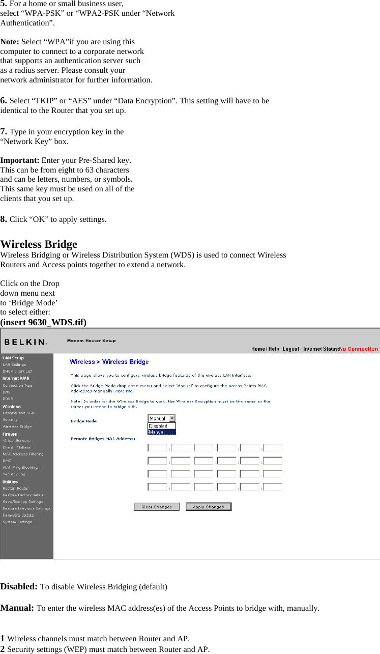
![3 If MAC filtering is enabled, user must be sure to add the WLAN MAC address(es) of the Router/AP in order to allow communication with each other. 4 If using a network protected by WPA, the SSID on both Access Points must be the same. Firewall Your Router is equipped with a firewall that will protect your network from a wide array of common hacker attacks including: • IP Spoofing • Land Attack • Ping of Death (PoD) • Denial of Service (DoS) • IP with zero length • Smurf Attack • TCP Null Scan • SYN flood • UDP flooding • Tear Drop Attack • ICMP defect • RIP defect • Fragment flooding The firewall also masks common ports that are frequently used to attack networks. These ports appear to be “Stealth”, meaning that essentially they do not exist to a would-be hacker. You can turn the firewall function off if needed; however, it is recommended that you leave the firewall enabled. Disabling the firewall protection will not leave your network completely vulnerable to hacker attacks, but it is recommended that you leave the firewall enabled. [use existing screenshot] Virtual Servers Virtual servers allow you to route external (Internet) calls for services such as a web server (port 80), FTP server (Port 21), or other applications, through your Router to your internal network. Since your internal computers are protected by a firewall, machines from the Internet cannot get to them because they cannot be “seen”. If you need to configure the virtual server function for a specific application, you will need to contact the application vendor to find out which port settings you need. You can manually input this port information into the Router. [use existing screenshot]](https://usermanual.wiki/Belkin/F5D9630-4V2/User-Guide-729994-Page-37.png)
![Choosing an Application A list of popular applications has been included to choose from. Click on “Select a Service” then select your application from the drop-down list. The settings will be transferred to the first row available. Click “Add” to save the setting for that application. Manually Entering Settings into the Virtual Server To manually enter settings, click on “Custom Server” and enter a name for the server. Enter the Server IP address in the space provided for the internal machine and the port(s) required to pass. Then select the protocol type (TCP or UDP), and then click “Add”. Opening ports in your firewall can pose a security risk. You can enable and disable settings very quickly. It is recommended that you disable the settings when you are not using a specific application. Client IP Filters The Router can be configured to restrict access to the Internet, email, or other network services at specific days and times. [use existing screenshot]](https://usermanual.wiki/Belkin/F5D9630-4V2/User-Guide-729994-Page-38.png)
![(1) (2) (3) (4) To restrict Internet access to a single computer for example, enter a name of the filter in “Filter Name” box (1) and IP address of the computer you wish to restrict access to in the IP field (2). Next, enter “80:80” in the Port field (3). Select protocol from the “Protocol” drop-down box (4). Click “Apply Changes”. The computer at the IP address you specified will now be blocked from Internet access. MAC Address Filtering The MAC address filter is a powerful security feature that allows you to specify which computers are allowed on the network. Any computer attempting to access the network that is not specified in the filter list will be denied access. When you enable this feature, you must enter a name for the user and the MAC address of each client on your network to allow network access. Next, click “Add” to save the settings. [use existing screenshot] DMZ (Demilitarized Zone) If you have a client PC that cannot run an Internet application](https://usermanual.wiki/Belkin/F5D9630-4V2/User-Guide-729994-Page-39.png)
![properly from behind the firewall, you can open the client up to unrestricted two-way Internet access. This may be necessary if the NAT feature is causing problems with an application such as a game or video conferencing application. Use this feature on a temporary basis. The computer in the DMZ is not protected from hacker attacks. [use existing screenshot] To put a computer in the DMZ, enter its LAN IP address in the “Private IP” field and click “Apply Changes” for the change to take effect. Blocking an ICMP Ping Computer hackers use what is known as “pinging” to find potential victims on the Internet. By pinging a specific IP address and receiving a response from the IP address, a hacker can determine that something of interest might be there. The Router can be set up so it will not respond to an ICMP ping from the outside. This heightens the level of security of your Router. To turn off the ping response, select “Block ICMP Ping” (1) and click “Apply Changes”. The Router will not respond to an ICMP Ping. [use existing screenshot]](https://usermanual.wiki/Belkin/F5D9630-4V2/User-Guide-729994-Page-40.png)
![Security Log Utilities The “Utilities” screen lets you manage different parameters of the Router and perform certain administrative functions. [use existing screenshot]](https://usermanual.wiki/Belkin/F5D9630-4V2/User-Guide-729994-Page-41.png)
![Restart Router Sometimes it may be necessary to restart or reboot the Router if it begins working improperly. Restarting or rebooting the Router will NOT delete any of your configuration settings. [use existing screenshot] Restarting the Router to Restore Normal Operation 1. Click the “Restart Router” button. 2. The following message will appear. Click “OK” to restart your Router. [use existing screenshot] Restore Factory Defaults Using this option will restore all of the settings in the Router to the factory (default) settings. It is recommended that you back up your settings before you restore all of the defaults. [use existing screenshot]](https://usermanual.wiki/Belkin/F5D9630-4V2/User-Guide-729994-Page-42.png)
![1. Click the “Restore Defaults” button. 2. The following message will appear. Click “OK” to restore factory defaults. [use existing screenshot] Saving/Backup Current Settings You can save your current configuration by using this feature. Saving your configuration will allow you to restore it later if your settings are lost or changed. It is recommended that you back up your current configuration before performing a firmware update. [use existing screenshot] 1. Click “Save”. A window called “File Download” will open. Click “Save”. [use existing screenshot] 2. A window will open that allows you to select the location in which to save the configuration file. Select a location. There are no restrictions on the file name, however, be sure to name the file so you can locate it yourself later. When you have selected the](https://usermanual.wiki/Belkin/F5D9630-4V2/User-Guide-729994-Page-43.png)
![location and entered the file name, click “Save”. [use existing screenshot] 3. When the save is complete, you will see the window below. Click “Close”. [use existing screenshot] The configuration is now saved. Restore Previous Settings This option will allow you to restore a previously saved configuration. 1. Click “Browse”. A window will open that allows you to select the location of the configuration file. All configuration files end with a “.conf”. Locate the configuration file you want to restore and double-click on it. [use existing screenshot] 2. Then, click “Open”. Firmware Update From time to time, Belkin may release new versions of the Router’s firmware. Firmware updates contain feature improvements and fixes to problems that may have existed. When Belkin releases new firmware, you can download the firmware from the Belkin update website and update your Router’s firmware to the latest version. [use existing screenshot]](https://usermanual.wiki/Belkin/F5D9630-4V2/User-Guide-729994-Page-44.png)
![Updating the Router’s Firmware 1. In the “Firmware Update” page, click “Browse”. A window will open that allows you to select the location of the firmware update file. [use existing screenshot] 2. Browse to the firmware file you downloaded. Select the file by double-clicking on the file name. 3. Click “Update” to upgrade to the latest firmware version. System Settings The “System Settings” page is where you can enter a new administrator password, set the time zone, enable remote management, and turn on and off the UPnP function of the Router. Setting or Changing the Administrator Password The Router ships with NO password entered. If you wish to add a password for greater security, you can set a password here. Write down your password and keep it in a safe place, as you will need it if](https://usermanual.wiki/Belkin/F5D9630-4V2/User-Guide-729994-Page-45.png)
![you need to log into the Router in the future. It is also recommended that you set a password if you plan to use the remote management feature of your Router. [use existing screenshot] Changing the Login Time-Out Setting The login time-out option allows you to set the period of time that you can be logged into the Router’s advanced setup interface. The timer starts when there has been no activity. For example, you have made some changes in the advanced setup interface, then left your computer alone without clicking “Logout”. Assuming the time-out is set to 10 minutes, then 10 minutes after you leave, the login session will expire. You will have to log into the Router again to make any more changes. The login time-out option is for security purposes and the default is set to 10 minutes. Note: Only one computer can be logged into the Router’s advanced setup interface at one time. Setting the Time and Time Zone The Router keeps time by connecting to a Simple Network Time Protocol (SNTP) server. This allows the Router to synchronize the system clock to the global Internet. The synchronized clock in the Router is used to record the security log and control client filtering. Select desired NTP time servers and the time zone that you reside in, then click “Apply Changes”. The system clock may not update immediately. Allow at least 15 minutes for the Router to contact the time servers on the Internet and get a response. You cannot set the clock yourself. [use existing screenshot] Enabling Remote Management Before you enable this advanced feature of your Belkin Router, MAKE SURE YOU HAVE SET THE ADMINISTRATOR PASSWORD. Remote management allows you to make changes to your Router’s settings from anywhere on the Internet. Click on the “Change Settings” button to bring up the “Remote Management” page. There are two methods of remotely managing the Router. The first is to allow access to the Router from anywhere on the Internet by selecting “Any IP address can remotely manage the Router”. By typing in your WAN IP address from any computer on the Internet, you will be presented with a login screen where you need to type in the password of your Router. The second method is to allow a specific IP address only to remotely manage the Router. This is more secure, but less convenient. To use this method, enter the IP address you know you will be accessing the Router from in the space provided and select “Only this IP address can remotely manage the Router”. Before you enable this function, it is STRONGLY RECOMMENDED that you set your administrator password. Leaving the password empty will potentially open your Router to intrusion.](https://usermanual.wiki/Belkin/F5D9630-4V2/User-Guide-729994-Page-46.png)
![[use existing screenshot] Click on the “Apply Changes” button to save your settings. Enabling/Disabling UPnP UPnP (Universal Plug-and-Play) is yet another advanced feature offered by your Belkin Router. It is a technology that offers seamless operation of voice messaging, video messaging, games, and other applications that are UPnP-compliant. Some applications require the Router’s firewall to be configured in a specific way to operate properly. This usually requires opening TCP and UDP ports, and in some instances, setting trigger ports. An application that is UPnPcompliant has the ability to communicate with the Router, basically “telling” the Router which way it needs the firewall configured. The Router ships with the UPnP feature disabled. If you are using any applications that are UPnP-compliant, and wish to take advantage of the UPnP features, you can enable the UPnP feature. Click on the “Change Setting” button to bring up the “UPnP Setting” page. Then select “On” for “Enable UPnP”. Click on the “Apply Changes” button to save your settings.](https://usermanual.wiki/Belkin/F5D9630-4V2/User-Guide-729994-Page-47.png)
![[use existing screenshot] Troubleshooting Problem: The ADSL LED is not on. Solution: 1. Check the connection between the Router and ADSL line. Make sure the cable from the ADSL line is connected to the port on the Router labeled “DSL Line”. 2. Make sure the Router has power. The Power LED on the front panel should be illuminated. Problem: The Internet LED is not on. Solution: 1. Make sure the cable from the ADSL line is connected to the port on the Router labeled “DSL Line” and the ADSL LED is on. 2. Make sure you have the correct VPI/VCI, user name, and password from your ISP provider. Problem: My connection type is static IP address. I can’t connect to the Internet. Solution: Since your connection type is static IP address, your ISP must assign you the IP address, subnet mask, and gateway address. Instead of using the Wizard, go to “Connection Type”, and then select your connection type. Click “Next”, select “Static IP”, and enter your IP address, subnet mask, and default gateway information. Problem: I’ve forgotten or lost my password. Solution: Press and hold the “Reset” button on the rear panel for at least 10 seconds to restore the factory defaults. Problem: My wireless PC cannot connect to the Router. Solution: 1. Make sure the wireless PC has the same SSID settings as the Router, and you have the same security settings on the clients such as WPA or WEP encryption. 2. Make sure the distance between the Router and wireless PC are not too far away. Problem:](https://usermanual.wiki/Belkin/F5D9630-4V2/User-Guide-729994-Page-48.png)
![Belkin Corporation Limited Lifetime Product Warranty Belkin Corporation warrants this product against defects in materials and workmanship for its lifetime. If a defect is discovered, Belkin will, at its option, repair or replace the product at no charge provided it is returned during the warranty period, with transportation charges prepaid, to the authorized Belkin dealer from whom you purchased the product. Proof of purchase may be required. This warranty does not apply if the product has been damaged by accident, abuse, misuse, or misapplication; if the product has been modified without the written permission of Belkin; or if any Belkin serial number has been removed or defaced. THE WARRANTY AND REMEDIES SET FORTH ABOVE ARE EXCLUSIVE IN LIEU OF ALL OTHERS, WHETHER ORAL OR WRITTEN, EXPRESSED OR IMPLIED. BELKIN SPECIFICALLY DISCLAIMS ANY AND ALL IMPLIED WARRANTIES, INCLUDING, WITHOUT LIMITATION, WARRANTIES OF MERCHANTABILITY AND FITNESS FOR A PARTICULAR PURPOSE. No Belkin dealer, agent, or employee is authorized to make any modification, extension, or addition to this warranty. BELKIN IS NOT RESPONSIBLE FOR SPECIAL, INCIDENTAL, OR CONSEQUENTIAL DAMAGES RESULTING FROM ANY BREACH OF WARRANTY, OR UNDER ANY OTHER LEGAL THEORY, INCLUDING BUT NOT LIMITED TO, LOST PROFITS, DOWNTIME, GOODWILL, DAMAGE TO OR REPROGRAMMING OR REPRODUCING ANY PROGRAM OR DATA STORED IN, OR USED WITH, BELKIN PRODUCTS. Some states do not allow the exclusion or limitation of incidental or consequential damages or exclusions of implied warranties, so the above limitations or exclusions may not apply to you. This warranty gives you specific legal rights, and you may also have other rights that vary from state to state. [Back Cover] Belkin Ltd. Express Business Park, Shipton Way Rushden, NN10 6GL, United Kingdom +44 (0) 1933 35 2000 +44 (0) 1933 31 2000 fax Belkin B.V. Boeing Avenue 333 1119 PH Schiphol-Rijk, The Netherlands +31 (0) 20 654 7300 +31 (0) 20 654 7349 fax Belkin GmbH Hanebergstrasse 2 80637 Munich, Germany +49 (0) 89 143405 0 +49 (0) 89 143405 100 fax Belkin SAS 130 rue de Silly 92100 Boulogne-Billancourt, France +33 (0) 1 41 03 14 40 +33 (0) 1 41 31 01 72 fax © 2006 Belkin Corporation. All rights reserved. All trade names are registered trademarks of respective manufacturers listed. Apple, AirPort, Mac, Mac OS, and AppleTalk are trademarks of Apple Computer, Inc., registered in the U.S. and other countries. The mark “Wi-Fi” is a registered mark of the Wi-Fi Alliance. Please add new P#](https://usermanual.wiki/Belkin/F5D9630-4V2/User-Guide-729994-Page-61.png)