Bellmate W150W WIRELESS CONTROLLER, AC24V User Manual W150W FCC
Bellmate Holdings Ltd. WIRELESS CONTROLLER, AC24V W150W FCC
Bellmate >
Users Manual

W150W USER MANUAL
SPECIFICATION
1. Power source:24V/AC(18~30V).
2. Static current ≤ 13 MA/AC24V
3. Backlight current ≤ 23 MA/AC24V
4. Blue backlight
5. Backlight brightness:15——55 LUX
6. Modulation mode: ASK
7. Frequency:916MHz
8. Transmission distance: 120 meter
OPERATION
1. Connect it to power, LCD will show full display. Repeater stays in transmission mode
(this is TX testing mode). Press key once and reference number will display, it enters into
receiving mode (this is RX testing mode).
2. Press the key to select reference number (1- 4), blue back light turn on. Without further
pressing on key, the number will flash 5 seconds and stop flashing. Blue backlight will turn
on in 15 seconds without key pressing.
3. When W150W received signal from TX, symbol will flash 3 times, then red LED flash,
LCD display symbol 6 times, it means W150W has been transmitted the received data.
4. Repeat models with reference number.
Reference Number Repeat models
1 Z270W, Z260W.
2 R250W, ZDA250W, R251W, Z251W.
3 B270W, B270WH.
4 W160W
FCC ID UX2W150W
This device complies with Part 15 of the FCC Rules. Operation is subject to the following two
conditions: (1) this device may not cause harmful interference, and (2) this device must accept
any interference received, including interference that may cause undesired operation.
NOTE:THE MANUFACTURER IS NOT RESPONSIBLE FOR ANY RADIO OR TV INTERFERENCE
CAUSED BY UNAUTHORIZED MODIFICATIONS TO THIS EQUIPMENT. SUCH MODIFICATIONS
COULD VOID THE USER’S AUTHORITY TO OPERATE THE EQUIPMENT.

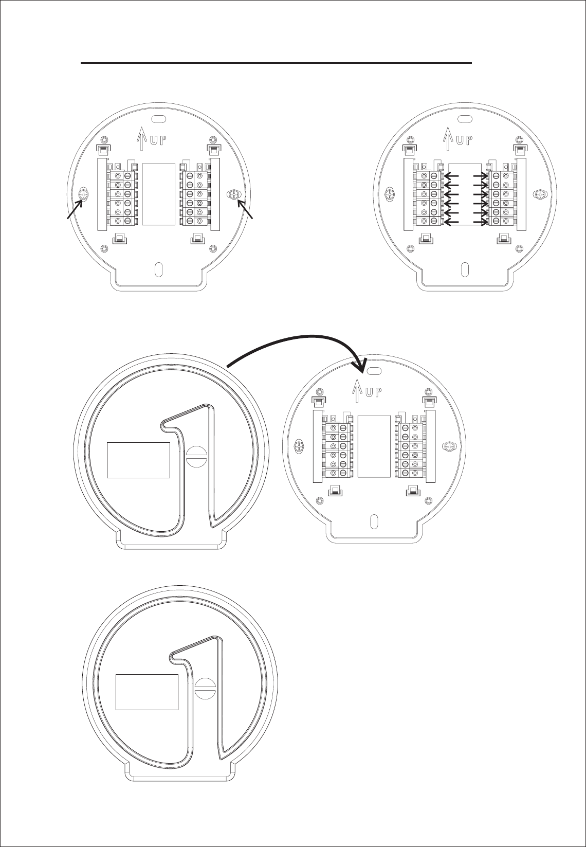
W150W INSTALLATION GUIDE
1. wall with screwFix the bottom panel on the
3. .Install the product on the bottom panel
4.Installation completion;
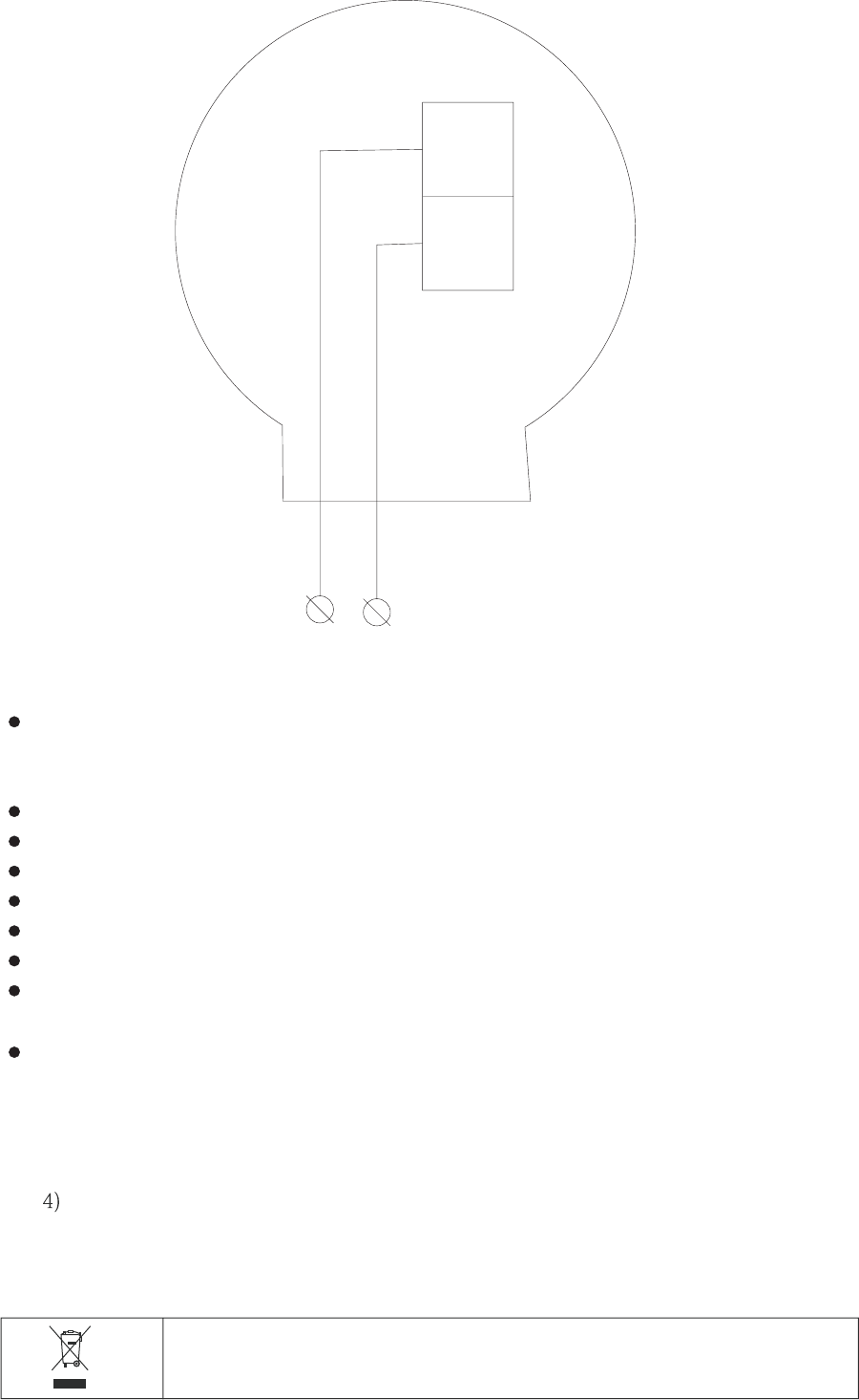
2. Connect all wires properly.

.
You can help protect the environment!
Please remember to respect the local regulations hand in the non working:-
electrical equipments to an appropriate waste disposal center.
The control is for installed by expert technician and in accorance with the writing
diagram during installation the application electrical safety regulation and the local,
electricity supply company regulations must be observed
Not to be exposed to dripping or splashing
For installation no metal conduit or of cable provided with a metal sheath,
The thermostat must be mounted on clean dry indoor place,
The unit is for fixed wiring conductors with current carried by terminal up A1
Disconnect from supply before open
Recommend to add fuse of A in the line circuit6
The size of wire connect to the terminal is to mm1.5 2
The thermostat must be placed in circuits of over voltage category with a maximum-1
working voltage not exceeding VAC those places are24 . :
1) the secondary side if transformer
2) 2)protected circuits
3) :1The curent should not exceed A
Symbol indicating separate collextion for electrical and electronic equipment.
R
C
Power AC V:24