Bellsouth E911 Users Manual
E911 to the manual 98e9d60e-61da-43f5-94c6-cd1ab3cb2701
2015-02-05
: Bellsouth Bellsouth-E911-Users-Manual-356898 bellsouth-e911-users-manual-356898 bellsouth pdf
Open the PDF directly: View PDF ![]() .
.
Page Count: 1

Customer Guide
CG-EWCG-001
Issue 3, January 6, 2004
Wireless E911 Guide

Wireless E911 Guide CG-EWCG-001
Copyright Issue 3, January 6, 2004
Copyright
April, 2002 - January 6, 2004
© BellSouth
Page ii

CG-EWCG-001 Wireless E911 Guide
Issue 3, January 6, 2004 Table of Contents
Contents
Subject Page
Introduction / Revision History . . . . . . . . ............................. vii
Purpose ...................................................... vii
Version Information .............................................. vii
1. Overview of E911 . . . . ....................................... 1
1.1 Definition of E911 ............................................. 1
1.1.1 Selective Routing ........................................... 1
1.1.2 Automatic Number Identification (ANI) ............................. 1
1.1.3 Automatic Location Identification (ALI) ............................ 1
1.1.4 Premises Based ALI Systems .................................... 2
1.2 PSAP Display ................................................ 2
1.3 Databases Required to Support E911 ................................. 3
1.4 Master Street Address Guide (MSAG) ................................ 3
1.5 Telephone Number (TN) Database .................................. 3
1.6 E911 Tandem / Network Information ................................. 4
1.7 Glossary of Terms ............................................. 5
1.8 Database Escalation Procedures .................................... 8
1.8.1 Access To NDSC Analysts ..................................... 8
1.8.2 Level One Escalation: Intrado ................................... 8
1.8.3 Level Two Escalation: Intrado ................................... 8
1.8.4 Level Three Escalation: Bellsouth ................................. 8
2. Coordination of Wireless Interconnection . . . . . . . ................... 9
2.1 Overview ................................................... 9
2.2 Coordination Process: Wireless Carrier ............................... 9
2.3 Coordination Process: BST Wireless Account Team ....................... 10
2.4 Coordination Process: BST Wireless E911 Implementation Manager ............ 10
2.5 Coordination Process: Mobile Position Center Provider ..................... 11
2.5.1 Steps for Establishment/Change of Mobile Position Center Provider ........... 11
2.5.2 Initial Establishment of Mobile Position Center Provider .................. 12
2.5.3 Change of Mobile Position Center Provider ........................... 12
2.5.4 Information Required for Phase 2 MPC/GMLC Circuits to the ALI Hosts ....... 12
2.5.5 Forms ................................................... 13
3. Network Specifications and Ordering ............................. 15
3.1 Overview ................................................... 15
3.2 Specifications & Ordering Process: .................................. 15
3.2.1 Option 1: BellSouth NORTEL Solution Carring Phase 1 Data Only (CBN & pANI) 15
3.2.2 Specification & Ordering Process: Option 2: Third Party Vendor Solution ....... 16
3.3 Wireless Carrier Owned Hardware .................................. 16
3.3.1 Trunking ................................................. 16
3.3.2 Data Connections Required For Wireless Carrier Owned Hardware - Phase 1 Only . 17
3.4 Wireless Phase 2 .............................................. 17
Page iii

Wireless E911 Guide CG-EWCG-001
Table of Contents Issue 3, January 6, 2004
3.5 Interface Testing .............................................. 18
4. MSAG Maintenance and ESN Assignment . . . . . . . ................... 19
4.1 Overview ................................................... 19
4.2 ESN Assignments ............................................. 19
4.3 MSAG Maintenance and Validation .................................. 20
5. TN Database Updates . ....................................... 23
5.1 Overview ................................................... 23
5.2 TN Database Daily Updates: Wireless Carrier Responsibilities ................ 24
5.3 E911 Customer Responsibilities .................................... 26
5.4 Instructions for NXX Table Update Form .............................. 27
5.5 NXX Table Update Form . . ...................................... 29
5.6 MSAG Formatting ............................................. 30
5.6.1 Correct Format ............................................. 30
5.6.2 Incorrect Format ............................................ 30
5.7 Standard Street Suffix (Thoroughfare) Designations / Directionals .............. 31
5.7.1 BellSouth Street Suffix (Thoroughfare) Abbreviations (Table) ............... 31
5.8 Standard Location Designations .................................... 32
5.9 Updating the TN Database . . ...................................... 33
5.10 Service Order Interface File Specifications ............................. 34
5.11 SOIR File Data Record Layout ..................................... 34
5.11.1 Table: SOIR File Data Record - BellSouth 512 Character Format for Data Exchange 34
5.12 SOIR File Header Record Layout ................................... 40
5.12.1 Table: SOIR File Header Record - BellSouth 512 Character Format for Data
Exchange ................................................ 40
5.13 SOIR File Trailer Record Layout ................................... 40
5.13.1 SOIR File Trailer Record - BellSouth 512 Character Format for Data Exchange . . . 40
5.14 Mechanized File Transfer . . ...................................... 41
5.15 Mechanized File Confirmations .................................... 41
6. TN Errors and Corrective Action . . . . ............................. 43
6.1 Overview ................................................... 43
6.2 Electronic Error Delivery . . ...................................... 43
6.2.1 The Confirmation Report ...................................... 43
6.2.2 The Statistics Report . . . ...................................... 46
6.2.3 Distribution of Daily Reports .................................... 47
6.2.4 TN Error Deletion ........................................... 48
6.3 Error Codes and Error Descriptions .................................. 48
6.4 Error Code and Corrective Action ................................... 50
6.5 Compiled Error Report .......................................... 58
7. PSAP Inquiries . . . . . . ....................................... 59
7.1 Overview ................................................... 59
7.2 PSAP Inquiry Form ............................................ 60
7.3 PSAP Inquiry Log ............................................. 61
7.3.1 Instructions for Completing PSAP Inquiry Log ........................ 61
7.4 Inquiry Flow ................................................ 62
7.5 Investigation Procedures . . . ...................................... 62
Page iv

CG-EWCG-001 Wireless E911 Guide
Issue 3, January 6, 2004 Table of Contents
7.5.1 ALI Record Not Found . . ...................................... 62
7.5.2 Wrong ALI Display Of: . ...................................... 62
7.5.3 Address — Community — Location ............................... 62
7.5.4 ESN .................................................... 63
7.5.5 Misroutes ................................................ 63
7.6 Blank Forms ................................................. 63
7.6.1 PSAP Inquiry Log ........................................... 64
8. No Record Found (NRF) Processing . ............................. 65
8.1 Overview ................................................... 65
8.2 No Record Found (NRF) Processing ................................. 65
8.3 No Record Found (NRF) Report Schedule ............................. 65
8.4 No Record Found (NRF) Report Layout ............................... 66
8.5 NRF Investigation ............................................. 66
9. NENA Company Registration Process . . . . . . . . . ................... 69
9.1 NENA Cmpany ID Registration Service ............................... 69
9.2 Purpose of the NENA Company ID Registration Service .................... 69
9.3 Use of the Service ............................................. 70
9.4 Instructions ................................................. 70
9.4.1 Input Form ................................................ 70
10. Reconciliation . . . . . . . ....................................... 73
10.1 Overview ................................................... 73
10.2 Notification and Scheduling . ...................................... 73
10.3 ......................................................... 73
Appendix A. BellSouth Wireless E9–1–1/SS7 Interconnection Guide . . . . . . . . 75
A.1 BellSouth Wireless E-9–1–1/SS7 Interconnection Guide .................... 75
A.2 Executive Summary ............................................ 75
A.2.1 Identified Options: ........................................... 76
A.2.1.1 Call Scenario 1, ESRK Delivery .................................. 76
A.2.1.2 Call Scenario 2, CBN and ESRD Delivery - WITHOUT a hybrid: (WITHOUT a
hybrid architecture at the Selective Router) ........................... 77
A.2.1.3 Call Scenario 2, CBN and ESRD Delivery - WITH a hybrid: (WITH a hybrid
architecture at the Selective Router) ................................ 77
A.2.1.4 Call Scenario 3, CBN, ESRD and GLP Delivery: (GLP = Geodetic Location
Parameter) ................................................ 77
A.2.2 Database Steering Options ...................................... 78
A.3 Scope and introductory text . ...................................... 78
A.3.1 Wireless E9-1-1 Service Introduction ............................... 78
A.4 Reason for Revision ............................................ 79
A.5 Organization of this Document ..................................... 79
A.6 Wireless CCS Network Interconnection Architecture ....................... 81
A.6.1 General Interconnection Information ............................... 81
A.6.2 Wireless Phase 1 vs. Phase 2 .................................... 81
A.7 Interface Protocol for Wireless Call Setup when using SS7/ISUP signaling. ....... 83
A.7.1 Calling Party Number . . ...................................... 83
A.7.2 Calling Party Number Parameter .................................. 84
Page v

Wireless E911 Guide CG-EWCG-001
Table of Contents Issue 3, January 6, 2004
A.7.3 Generic Digits Parameter & GDP Type ............................. 84
A.7.4 Charge Number Parameter ..................................... 85
A.7.5 Calling Party Category Parameter (CPC, aka: CPCat) .................... 85
A.7.6 Originating Line Information Parameter ............................. 85
A.8 Cross Reference Tables to J-STD-036-A ............................... 86
A.8.1 Wireline Compatibility Mode (NDET uses signaling option E911_STD) ........ 86
A.8.2 ISUP Initial Address Message Parameter Contents for NCAS (NDET uses signaling
option WRLS_STD, because MSC can support GDP) .................... 87
A.8.3 ISUP Initial Address Message Parameter Contents for NCAS (NDET uses signaling
option WRLS_CLD because MSC cannot support GDP) .................. 88
A.8.4 ISUP Initial Address Message Parameter Contents for CAS ................ 90
A.9 Cross Reference Tables to NENA TID 05-501 - SS7 Guidelines for MSC to Selective
Router Connectivity. ........................................... 91
A.9.1 Call Scenario 1: ESRK Delivery .................................. 92
A.9.2 8.2 Call Scenario 2: CBN and ESRD Delivery ......................... 92
A.10 Attachment "A" - CPCat & OLI Notes ................................ 94
A.10.1 Calling Party Category parameter (CPC): ............................ 94
A.10.2 Originating Line Parameter (OLI): ................................ 94
A.11 Attachment "B" - Wireless Customer Questions & Answers: .................. 95
A.11.1 Why is BellSouth issuing this document? ............................ 95
A.11.2 Do I have to change my existing trunks to SS7? ........................ 95
A.11.3 Will this let me deliver ESRDs/ESRKs from more than one NPA on the SS7 trunk
group? .................................................. 95
A.11.4 Will this let me reduce the number of trunk groups I have in place? ........... 95
A.11.5 What if I don’t have SS7 signaling "A" link connectivity to support trunking to the
appropriate NDET? .......................................... 96
A.11.6 What do I do for Continuity Testing on these SS7 trunks? ................. 96
A.12 11.0 Attachment "C" - Wireless Customer Checklist ....................... 96
Page vi

CG-EWCG-001 Wireless E911 Guide
Issue 3, January 6, 2004 Introduction / Revision History
Introduction / Revision History
Purpose
This document addresses Wireless E911.
Version Information
Added SS7/ISUP signaling option for trunking between the MSC and E911 tandems. Added Appendix A.
Page vii

Wireless E911 Guide CG-EWCG-001
Introduction / Revision History Issue 3, January 6, 2004
Table A Revision History
Chapter Action
Request
#
Date / Issue Description Change
Requested By /
Made By
All N/A January 6, 2004 /
3Added SS7/ISUP signaling
option for trunking between
the MSC and E911 tandems.
Added Appendix A.
Tom Breen / Bill
Marczak / Mike
Harfield
MSAG Maintenance
and ESN Assignment N/A May 22, 2003 / 2b Revised SOIR File Data
Record Layout Table to
show "Sent to PSAP" field
footnotes in table column.
Rosemary Parker /
Mike Harfield
Overview of E911;
Coordination
of Wireless
Interconnection;
Network
Specifications and
Ordering
N/A April 3, 2003 / 2a Overview of E911: Added
"GMLC" Term, Changed
contact for "Level One
Escalation: Intrado".
Coordination of Wireless
Interconnection: Added
"Coordination Process:
Mobile Position Center
Provider"
Network Specifications and
Ordering: Added "Wireless
Phase 2".
Genia Harris /
Mike Harfield
TN Database Updates N/A January 8, 2003 /
2Corrected FAX numbers. Rosemary Parker /
Mike Harfield
TN Database Updates
and PSAP Inquiries N/A December 2, 2002
/1c Added step in TN Database
Daily Updates: Wireless
Carrier Responsibilities and
changed address in Inquiry
Flow for INTRADO.
Rosemary Parker /
Mike Harfield
- continued -
Page 8

CG-EWCG-001 Wireless E911 Guide
Issue 3, January 6, 2004 Introduction / Revision History
Table A Revision History (continued)
Chapter Action
Request
#
Date / Issue Description Change
Requested By /
Made By
All N/A July 15, 2002 / 1b Revisions to sections
entitled, "Overview of
E911", "Coordination of
Wireless Interconnection",
and "Network Specifications
and Ordering".
Rosemary Parker /
Mike Harfield
Various N/A June 20, 2001 / 1a General revisions to section
entitled "TN Errors and
Corrective Action"
Rosemary Parker /
Mike Harfield
All N/A April 4, 2002 / 1 Initial Issue Rosemary Parker /
Mike Harfield
Page 9

Wireless E911 Guide CG-EWCG-001
Introduction / Revision History Issue 3, January 6, 2004
Page 10

CG-EWCG-001 Wireless E911 Guide
Issue 3, January 6, 2004 Overview of E911
1. Overview of E911
1.1 Definition of E911
"911" has been designated in the United States as the number to be used by the public to summon
emergency aid or to report a crime, fire or accident. Its main purpose is to make it easier for people in time
of emotional stress to contact the proper emergency agency. An important advantage of 911 emergency
service is improved (reduced) response time.
The original 911 service, known as Basic 911 (B911), routes a call to one centralized answering location.
The attendant at the answering location obtains the pertinent information that identifies the call and the
caller’s need. The attendant then determines the appropriate agency and dials the number to transfer
the caller to that agency.
Enhanced 911 service, or E911, is a full featured electronic system that provides three (3) major
enhancements to Basic 911 service:
1.1.1 Selective Routing
Electronically routes 911 emergency calls to the proper Public Safety Answering Point (PSAP) based
on the Emergency Service Number (ESN) code that has been assigned to the cell site address or the
longitude/latitude of the caller’s location. This may be accomplished by assigning "pseudo-ANI"
telephone numbers to each face of each antenna in order to designate a fixed location for the serving
area. Some wireless solutions allow the assignment of a pseudo-ANI telephone number to a specific
PSAP rather than an antenna face. An ESN is assigned to the "pseudo-ANI" telephone numbers during
database record processing and is assigned from the Master Street Address Guide (MSAG) based on
the address. Some solutions may dynamically assign the ESN based upon the longitude/latitude of the
caller’s location. Wireless Carriers must work with the local governmental agencies and agree on call
routing, ESN assignments, and MSAG valid addresses. This process is described later in this document.
Wireless Carriers should identify selective routing capabilities for premises based ALI systems and make
arrangements to deliver wireless calls directly to the PSAP in those cases where selective routing is not
utilized. See Premises Based ALI Systems below.
1.1.2 Automatic Number Identification (ANI)
Provides the PSAP with the 7-digit pseudo-ANI telephone number representing the antenna face which
received the wireless 9-1-1 call or the pseudo-ANI PSAP routing number, depending on the wireless
solution implemented. Interfaces utilizing Feature Group D signaling between the E911 selective routing
tandem and the PSAP may be capable of sending 10-digit ANI or 10-digit ANI and 10-digit call back
number to the PSAP. Pseudo-ANI numbers must be assigned from the wireless carrier’s number range and
must be geographically valid for the E911 selective routing tandem service area.
1.1.3 Automatic Location Identification (ALI)
Provides the PSAP with cell site location information associated with the pseudo-ANI. Phase 1 compliance
also requires ALI to contain the wireless subscribers call back number. This may be accomplished by the
Page 1

Wireless E911 Guide CG-EWCG-001
Overview of E911 Issue 3, January 6, 2004
wireless carrier providing a real-time update to the ALI databases during 9-1-1 call processing. Phase
2 requires both of the data elements provided in Phase 1 plus the longitude and latitude of the caller’s
location when they dialed 9-1-1. BellSouth supports E2 connectivity between MPCs and the ALI database
hosts as defined in BellSouth Technical Reference TR73610, Issue 2. BellSouth will deliver the lat / long
data to the PSAP in the ALI response message as described in BellSouth Technical Reference TR73528,
Issue 6. Wireless Carriers must ensure dynamically updated records will comply with TR73528 when
delivered to the PSAP. These Technical References may be found on the following web site:
Note: To receive the maximum benefit of E911, the initial ALI database record must be assigned an
MSAG valid address even if the tower is located in a rural area. MSAG valid addresses are
obtained from the addressing authority in the E911 area where the cell site is located.
1.1.4 Premises Based ALI Systems
Premises based ALI systems may have a separate database, software, and hardware located on the E911
Customer premises. Wireless Carriers must identify all premises based systems in their service areas and
comply with any special data or interface requirements. Carriers should meet with PSAPs to determine
if selective routing or direct trunking is used to deliver 911 calls. If calls are not selectively routed to
premises based ALI systems, the carrier may need to deliver wireless 911 calls to the PSAP administrative
lines or use other arrangements as negotiated with the PSAP. This guide does not address issues related to
premises based ALI systems.
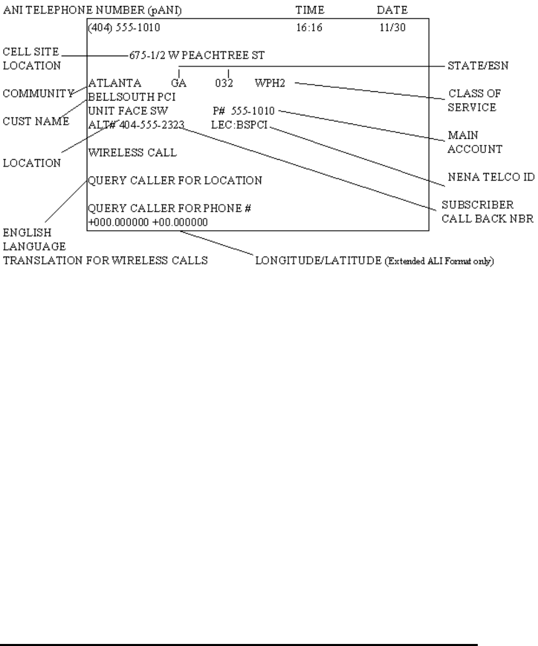
1.2 PSAP Display
The PSAP display for the ANI and ALI has been configured so that the PSAP attendant can immediately
recognize from the English Language Translations (ELT) that the call is being made from a wireless
device. The ALI response may contain the cell site sector location, subscriber call back number, and
lat/long when available. An example of a typical PSAP display is shown. This screen/display will vary
based on which PSAP equipment is chosen by the E911 Customer.
Page 2
CG-EWCG-001 Wireless E911 Guide
Issue 3, January 6, 2004 Overview of E911
1.3 Databases Required to Support E911
Three (3) data files (or databases) are required to provide the data for display at the PSAP:
• Master Street Address Guide (MSAG)
• Telephone Number (TN) Database
• E911 Tandem/Network Information (TN/ESN)
1.4 Master Street Address Guide (MSAG)
The MSAG contains all street information in the full featured E911 service area. The Emergency Service
Numbers (ESNs) are assigned to the streets for routing 911 calls to the proper PSAP. As data records for
the pseudo-ANI telephone numbers are processed from the wireless carriers, the address information on
the data record is validated against the MSAG. Address information on the data records must exactly match
the MSAG information or the data records will be considered an error and returned to the wireless carrier
for correction. Data records are not posted to the database until they pass validation.
1.5 Telephone Number (TN) Database
The TN database contains all of the wireline subscriber records and wireless pseudo-ANI records for all
carriers in the E911 service area. This information includes the telephone number, name of the wireline
subscriber, address, location, class and type of service. For the wireless carrier, it includes the pseudo-ANI
Page 3

Wireless E911 Guide CG-EWCG-001
Overview of E911 Issue 3, January 6, 2004
telephone number which has been assigned by the carrier, the carrier name, and the MSAG valid address
of the cell site sector location. A full description of the data fields in the TN database may be found
inTN Database Updates.
The TN database is updated by the wireless carrier on an ongoing basis as new pseudo-ANI numbers are
assigned or when existing information changes. This includes changes in antenna face coverage area when
it impacts routing of 911 calls to the appropriate PSAP. The data record which is sent by the wireless carrier
is validated against the MSAG for an exact address match and is assigned the appropriate ESN which is
loaded into the E911 host database and the E911 tandem routing database. Details for providing TN data
to the E911 host is explained later in this document. Some wireless solutions will dynamically update the
cell site location, call back number, longitude, and latitude during 911 call processing. Wireless carriers
are still required to provide "static" pseudo-ANI data records to the E911 host with MSAG valid addresses.
These "static" records will be dynamically updated during 911 call processing. The cell site location
information provided during the dynamic updates are not validated against the MSAG, but the original
"static" record provided in the SOIR process will be validated and must contain MSAG valid information.
Wireless Carriers must provide valid data records for inclusion in the TN database prior to testing or
activating service. If data records are not posted to the TN database, the PSAP will receive a "NO
RECORD FOUND" display when subscribers dial 911 which may delay getting them the emergency
services they need.
1.6 E911 Tandem / Network Information
Interconnection arrangements to the E911 tandem are negotiated with the wireless carrier’s BST
Interconnection Services Account Representative. The wireless carrier must provide a minimum of two
(2) Type 2C redundant trunks to the E911 tandem office(s) that will serve the Mobile Switching Center
(MSC). Additional facilities may be required depending on the technical solution used to dynamically pass
the wireless call back number and longitude/latitude to the ALI database. Data circuits must exist between
MPCs and the ALI database hosts for the E2 interface required for Phase 2.
Determining the proper PSAP to route wireless 911 calls must be negotiated between the wireless carrier
and the E911 Coordinators in the serving areas. This must also include the proper PSAP to receive the
wireless 911 call in the event of an ANI (pANI) failure from the MSC. All 911 calls will default route to
the negotiated PSAP when an ANI (pANI) failure occurs. E911 Coordinators must agree on the PSAP to
receive these calls. Once agreement has been reached with the E911 Coordinators, the wireless carrier will
notify the BST Interconnect Account Representative of the PSAP location for default routing. This will
allow for BST to establish the necessary translations in the E911 tandem office. The BST Interconnect
Account Representative may assist the wireless carrier in identifying which E911 tandem office should be
used to route calls to a specific PSAP.
Page 4

CG-EWCG-001 Wireless E911 Guide
Issue 3, January 6, 2004 Overview of E911
1.7 Glossary of Terms
Table B Glossary of Terms
Term Definition
ACAC Access Carrier Advocacy Center
Address Verification
Request (AVR) A form issued by each telco to refer and resolve address
discrepancies with the E911 Customer.
ALEC Alternative Local Exchange Carrier
Alternate Routing A standard feature provided to allow E911 calls to be routed to a
designated alternate location if :
1. all E911 trunks to the primary PSAP are busy OR
2. the primary PSAP closes down for a period. (i.e. night service)
Automatic Location
Identification (ALI) A feature by which the address associated with the telephone
number (ANI or pANI) is forwarded to the PSAP for display.
Automatic Number
Identification (ANI) The telephone number assigned by the wireless carrier to the cell
face or PSAP. Also known as Pseudo-ANI and Emergency Service
Routing Digits (ESRD).
Note: The pseudo-ANI number MUST be assigned from the
wireless carrier number pool and be geographically correct for the
serving area.
BST BellSouth Telecommunications, Inc.
Call Back Number Telephone number PSAP will use to dial the 911 caller in the event
the call is disconnected. Also known as wireless Mobile Directory
Number (MDN), Wireless Subscriber ANI (WS-ANI) and Calling
Party Number (CPN).
Call Through Testing The process of testing the network, equipment and database
associated with an E911 system prior to the final cutover.
CMRS Commercial Mobile Radio Service
CSU Channel Service Unit
DSU Data Service Unit
E2 Interface The TIA / EIA / J-STD-036 E2 interface utilized to provide phase
2 location information to the ALI database from the MPC. Refer
to BellSouth TR73610, Issue 2.
E911 Customer A governmental agency responsible for providing public safety and
purchasing 911 service.
- continued -
Page 5

Wireless E911 Guide CG-EWCG-001
Overview of E911 Issue 3, January 6, 2004
Table B Glossary of Terms (continued)
Term Definition
E911 Tandem Central
Office Switch The central office designated for a geographical area to receive end
office E911 calls and route to the appropriate PSAP.
Emergency Service
Number (ESN) A number associated with the geographical area served by the same
fire, police and ambulance districts.
Emergency Service
Routing Digits
(ESRD)
See ANI or pANI
End Office The central office switch receiving E911 calls from subscribers.
For wireless, this would be the MSC.
FCC Federal Communications Commission
FOC Function of Change
GMLC (see MPC)
ICO Independent Telephone Company
Integrated Services
Digital Network User
Part (ISUP)
A message protocol to support call set up and release for interoffice
voice call connections over SS7 signaling.
Intrado A vendor designated by BST to handle E911 data maintenance
(formerly SCC)
LOC Location
Master Street Address
Guide (MSAG) All street data, including street names, address ranges and ESNs
used to validate incoming telephone number data for provisioning
of selective routing.
Mobile Position Center
(MPC) The network entity that provides phase 2 location information to
the ALI database over an E2 interface. For the purposes of this
document, MPC and GMLC are considered equivalent although a
GMLC is unique to the GSM environment.
Mobile Switching
Center (MSC) Wireless equivalent of an End Office, which provides switching
functions from wireless calls.
National Emergency
Number Association
(NENA)
A professional association of 9-1-1 emergency number entities
responsible for the planning, implementation, management and
administration of national emergency number issues.
NPA The area code of the telephone number.
NRF No Record Found
NXX The first three(3) digits of a telephone number following the NPA.
- continued -
Page 6

CG-EWCG-001 Wireless E911 Guide
Issue 3, January 6, 2004 Overview of E911
Table B Glossary of Terms (continued)
Term Definition
Pseudo-ANI (pANI) The telephone number assigned by the wireless carrier to designate
a specific cell antenna face or PSAP. Also see Automatic Number
Identification (ANI).
Public Safety
Answering Point
(PSAP)
The answering location for 911 calls.
RCF Remote Call Forwarding
SALI Stand Alone Automatic Location Identification
SCC Communications A vendor designated by BST to handle E911 data maintenance
(now Intrado)
Selective Routing (SR) A standard feature that routes an E911call from the E911 tandem to
the designated PSAP based upon the address and assigned ESNof
the pseudo-ANI telephone number record.
Service Order Interface
Record (SOIR) A formatted data record sent to the E911 host computer system by
the wireless carrier. (see TSS)
Signaling System
7 (SS7)/Common
Channel Signaling 7
(CCS7)
An out-of-band signaling system used to provide basic routing
information, call set up and other call termination functions.
Signaling is removed from the voice channel and put on a separate
data network.
Subscriber Person or end user making a 911 call.
System ID A two(2) character code used to identify a tandem. (Assigned by
BST)
Tandem Routing An arrangement for connecting E911calls to the correct PSAP
based on the ESN associated to the pseudo-ANI telephone number
service address. (see Selective Routing)
Telco (Telephone
Company) A term used interchangeable throughout this document to depict a
Bell Operating Co., an Independent Company, an Alternative Local
Exchange Carrier (ALEC) or a Wireless service provider.
TN Telephone Number
Transaction Servicing
System (TSS) The BellSouth E911vendor’s computer system that performs
database processing.
WSANI Wireless Subscribers ANI (see ANI or pANI)
Note: Additional wireless and technical information may be found on the NENA web site at
http://nena9-1-1.org:Click here to access website.
Page 7

Wireless E911 Guide CG-EWCG-001
Overview of E911 Issue 3, January 6, 2004
1.8 Database Escalation Procedures
The following procedures have been established for Wireless Carrier escalation of database related issues
to BellSouth / Intrado: (Examples of these issues are, but not limited to: MSAG problems, NPA / NXX
updates, etc.)
The initial trouble / problem referral made by the Wireless Carrier should go to the Intrado NDSC
Data Analyst. The escalation process will normally begin after a referral is made to the NDSC with
unsatisfactory or no resolution.
1.8.1 Access To NDSC Analysts
DIAL 1-888-584-3810, AT THE PROMPT, ENTER THE APPROPRIATE EXTENSION NUMBER.
1.8.2 Level One Escalation: Intrado
Data Opns SUPERVISOR (Kelley Thomson) extension 6269
1.8.3 Level Two Escalation: Intrado
Data Opns MANAGER (Mike Wallace) extension 6270
1-888-584-3810
1.8.4 Level Three Escalation: Bellsouth
BellSouth Wireless E911 Implementation Manager: (205) 321-4785
If the problem has not been resolved by Intrado or the problem has not been resolved to the customer’s
satisfaction, the BellSouth Wireless E911 Implementation Manager should be contacted:
1. The BellSouth Wireless E911 Implementation Manager should be notified of the problem.
2. The BellSouth Wireless E911 Implementation Manager will involve the BellSouth
Address/911 Staff Support organization as required. All 911 / addressing issues should be
referred by the Wireless E911 Implementation Manager to the Address / 911 Staff.
3. The Address / 911 Staff Support group will investigate and resolve or escalate up to the highest
level necessary within BellSouth and / or Intrado. When the problem is resolved, A / 911
Staff Support will advise the Wireless E911 Implementation Manager who will notify the
customer of the resolution.
Page 8

CG-EWCG-001 Wireless E911 Guide
Issue 3, January 6, 2004 Coordination of Wireless Interconnection
2. Coordination of Wireless Interconnection
2.1 Overview
This section provides the Wireless Carrier with the steps necessary to interconnect with the BellSouth
(BST) E911 network.
The FCC Wireless Phase 1 Order requires the Wireless Carrier to provide both the cell site sector location
information and the wireless subscribers call - back number for wireless 911 calls. Phase 2 requires the
additional data fields longitude and latitude be provided to represent the location of the caller when they
dialed 911. Cell site sector location information is provided in "static" database records as described in
TN Database Updates. The subscriber’s call - back number, longitude, and latitude must be provided real
- time during 911call processing. Various technical solutions may be chosen by the Wireless Carrier to
provide the required data to the ALI database. Wireless Carriers must work with Intrado to ensure the
chosen solution is compatible with the BST ALI database interfaces. Some solutions allow the "static"
database records to be assigned on a PSAP basis with the cell site sector location information, call - back
number, and the longitude / latitude being provided real-time during 911 call processing.
Wireless Carriers must order Type 2C trunks for transmission of the voice and pseudo-ANI (pANI)
numbers to the E911 tandem. Some solutions may require SS7 / ISUP trunking between the wireless MSC
and the E911 tandem. If SS7 connectivity will be used, refer to Appendix A of this guide. In addition to
these trunks, Wireless Carriers may be required to order two(2) digital data circuits with secondary channel
to the BST Automatic Location Identification (ALI) computers. These circuits are necessary to provide
Phase 1 real-time updates to the ALI database for storing the wireless subscribers ten digit call-back
number and for some solutions, cell site sector location information. Two redundant ALI computers work
as a mated pair, therefore a digital data circuit is required to each of the two ALI computers. The need for
digital data circuits depends on the technical solution chosen. Steps to determine if there is a need, and
how to order these circuits, are described in this section.
Wireless Carriers must also provide E2 connectivity between the MPCs and the ALI database hosts
allowing Phase 2 location information to be populated in the ALI databases.
Interconnection to the BST E911 network involves the effort of various BST departments. The BST
Wireless Account Team and Wireless E911 Implementation Manager will be the coordinators between the
Wireless Carrier and the various BST departments to assist with steps necessary for interconnection.
2.2 Coordination Process: Wireless Carrier
The Wireless Carrier will notify the BST Wireless Account team and provide general information
concerning the request to interconnect to BST’s E911 network. This information should include the states,
counties, and / or parishes that are involved in the wireless coverage area, the method of interconnection to
the BST network, and the technical solution chosen to provide the wireless subscribers call - back number
and longitude / latitude to the ALI database, and E2 interface information.
Wireless Carriers must meet with each of the E911 Customers in the wireless coverage area to discuss cell
site locations, valid addresses and formats for static database records, ESN assignments, identification
Page 9

Wireless E911 Guide CG-EWCG-001
Coordination of Wireless Interconnection Issue 3, January 6, 2004
of the appropriate E911 tandem, 911 call routing, default routing for ANI failures, and assignment of
geographically valid pANI numbers from the wireless carrier’s number range. The E911 customers must
agree on which PSAP will accept 911 calls from the various cell sites including when ANI failures occur.
Wireless Carriers should also determine if the E911 Customers wish to segregate wireless 911 calls from
wireline 911 calls by implementing separate trunk groups to the PSAP. All premises based E911 databases
should be identified as well as any special procedures necessary to update those databases.
Carriers must also work directly with Intrado to include the Carrier’s pANI numbers in the appropriate
Security Tables and to identify the appropriate E2 interface to invoke for Phase 2.
A Service Inquiry must be initiated by the Wireless Carrier through the BST Account team for the Type
2C trunk connections and/or SS7 /ISUP trunks to the E911 tandems. If SS7 connectivity will be used,
refer to Appendix A of this guide. The BST Wireless E911 Implementation Manager will discuss with
the Wireless Carrier the process of ordering / provisioning the digital data circuits to the ALI computers,
if new circuits are required.
The Wireless Carrier must contact Intrado, the BST E911 database vendor, for all database related steps
necessary for the establishment and maintenance of wireless database records and interfaces to the ALI
computers. Carriers must post valid records in the E911 database prior to testing or turning up service.
Additional information related to database requirements is found in this guide.
Since access to E911 is a critical issue in today’s environment, it is necessary for the Wireless
Carrier to provide 24 X 7 contact name and telephone number information for maintenance and
trouble handling / clearing.
2.3 Coordination Process: BST Wireless Account Team
The BST Wireless Account team will receive the initial request from the Wireless Carrier and initiate the
BST Service Inquiry process for interconnection to the BST E911 network. The BST Account team will
contact the BST Wireless E911 Implementation Manager to begin the internal BST coordination process.
Various BST departments will review the Service Inquiry and update with additional required information.
The BST Account team will then complete form RF-1004WS and forward this form, along with a copy
of the Service Request, to the BST Wireless Service Center where service orders will be input into the
service order system.
A copy of the form RF-1004WS will also be distributed to the BST Implementation team and Intrado.
2.4 Coordination Process: BST Wireless E911 Implementation Manager
The BST Wireless E911 Implementation Manager will assist the Wireless Carrier with the requirements
for connecting to the BST E911 network. During this process the BST Wireless E911 Implementation
Manager will determine if it is necessary for the Wireless Carrier to order digital data circuits to the
BST ALI computers. The technical solution chosen by the Wireless Carrier will determine the need
for these data circuits:
Page 10

CG-EWCG-001 Wireless E911 Guide
Issue 3, January 6, 2004 Coordination of Wireless Interconnection
• If the Wireless Carrier is connecting to a DMS100 E911 tandem utilizing an existing Nortel
wireless connection to the ALI computers, no additional data circuits will be required for
Phase 1.
• If the Wireless Carrier provides their own wireless solution hardware in their network, the
Wireless Carrier must provide the data circuits.
• If the Wireless Carrier contracts with a third party to provide the connection to the ALI
computers, the data circuits should be provided by the third party.
• If new solutions are negotiated, the BST Wireless E911 Implementation Manager will work
with the Wireless Carrier and the BST team to determine the interconnection requirements
and process flow.
The BST Wireless E911 Implementation Manager will coordinate with the BST Wireless Access Carrier
Advocacy Center (ACAC) the provisioning, testing, and Wireless Carrier acceptance of the Type 2C
trunks to the BST E911 tandems as required. The BST Wireless E911 Implementation Manager will
also coordinate with the BST departments and Intrado, the provisioning, testing, and acceptance of new
data circuits to the ALI computers if applicable.
The BST Wireless E911 Implementation Manager will issue a Teleprocessing Request form to Intrado and
the BST IT Transport Group if new data circuits are required to the ALI computers.
As required, the BST Wireless E911 Implementation Manager will assist the Wireless Carrier through the
necessary processes required to complete the interconnection to the BST E911 network.
2.5 Coordination Process: Mobile Position Center Provider
The Wireless Carrier will be required to submit written notification naming the Mobile Position Center
(MPC) provider they have selected. Note that MPC and GMLC are equivalent with respect to this guide
although a GMLC is unique to the GSM environment. This written notification should be submitted to the
BST Wireless E911 Implementation Manager. Any subsequent change in MPC provider also requires
written notification naming the new provider selected.
2.5.1 Steps for Establishment/Change of Mobile Position Center Provider
The Wireless Carrier is required to provide written notification of their selected or modified MPC provider
to the BST E911 Implementation Manager via US Mail, electronic mail, or fax:
BST Wireless E911 Implementation Manager
Attn: John Storey
3535 Colonnade Parkway
Birmingham, AL 35243
Tel: 205-977-7653
Fax: 205-977-7692
Email: John.Storey@bellsouth.com
Page 11

Wireless E911 Guide CG-EWCG-001
Coordination of Wireless Interconnection Issue 3, January 6, 2004
2.5.2 Initial Establishment of Mobile Position Center Provider
The first step for the Wireless Carrier in establishing their MPC provider is to contact the BST Wireless
E911 Implementation Manager. At that time a discussion will take place to determine the method of
connectivity. The Wireless Carrier will be provided a questionnaire used to direct the Wireless Carrier
to the next steps required for Phase II connectivity. Once it has been determined what the needs of the
Wireless Carrier are, they will be directed to the appropriate network entity that will provide location
information to the ALI database. When the determination has been made, the Wireless Carrier will then be
asked to provide written notification to the BST Wireless E911 Implementation Manager as to who they
have selected as their MPC provider.
If the Wireless Carrier will use their own equipment and provide their own E2 Interface to BST, the
first step is to contact the BST ICS E911 Product Manager. The Wireless Carrier is required to sign the
Wireless E911 Phase 2 MPC Operator Interface Agreement and to work with the BST Wireless E911
Implementation Manager to connect the E2 circuits to the ALI databases.
2.5.3 Change of Mobile Position Center Provider
Should the Wireless Carrier change the MPC provider that was initially selected, written notification to the
BST Wireless E911 Implementation Manager will be required. This notification may be sent via US Mail,
electronic mail, or faxed to the address noted above.
2.5.4 Information Required for Phase 2 MPC/GMLC Circuits to the ALI Hosts
The following information can be used by Wireless Carriers or their MPC/GMLC providers in placing
orders for the E2 Data Links which will connect their MPCs or GMLCs to BellSouth’s ALI Host
Computers located in the 4 Data Centers. The BellSouth ALI Host Computers in Miami, FL and Charlotte,
NC serve FL, GA, NC and SC. The BellSouth ALI Host Computers in Birmingham, AL and Nashville, TN
serve LA, MS, AL, TN and KY. MPCs/GMLCs must be connected to the appropriate ALI host pairs for
the states served.
PLASE NOTE - the following also contains information related to these circuit orders which must be
returned to BellSouth’s Wireless E911 Implementation Manager as soon as it is available. This will aid
in completion of preliminary forms that must be provided in advance of the orders to the data center
personnel. to insure there are no delays in connecting and extending the circuits. Note that there is a
separate form for each of the BellSouth ALI Host Computer locations.
You should also contact Doug McCambridge at Intrado (720-494-6271) to schedule coordinated testing of
these circuits. Intrado requires at a minimum 5 days notice prior to testing. Questions/comments can be
directed to John Storey at 205-977-7653 or by e-mail at John.Storey@bellsouth.com.
Detailed Circuit Information (Circuit IDs for all segments of the circuits with 24 X 7 Contact names
and numbers, etc.) is required so that service technicians can communicate with each other in the
event of outages or maintenance issues.
Page 12

CG-EWCG-001 Wireless E911 Guide
Issue 3, January 6, 2004 Coordination of Wireless Interconnection
2.5.5 Forms
Birmingham DATA Center: (serving LA, MS, AL, TN, KY)
Nashville DATA Center: (serving LA, MS, AL, TN, KY)
Charlotte DATA Center: (serving FL, GA, NC, SC)
Miami DATA Center: (serving FL, GA, NC, SC)
Page 13

Wireless E911 Guide CG-EWCG-001
Issue 3, January 6, 2004
Page 14 - Blank

CG-EWCG-001 Wireless E911 Guide
Issue 3, January 6, 2004 Network Specifications and Ordering
3. Network Specifications and Ordering
3.1 Overview
This section provides the Wireless Carrier with the Network Specifications and Ordering Procedures to be
followed when ordering facilities to interconnect to the BST E911 network.
Due to the complex nature and many processes involved with interconnecting to the BST E911
network, coordination between the Wireless Carrier and the various BST organizations involved will
be accomplished through the Wireless Carrier’s Marketing Account team and the BST Wireless E911
Implementation Manager.
3.2 Specifications & Ordering Process:
3.2.1 Option 1: BellSouth NORTEL Solution Carring Phase 1 Data Only (CBN & pANI)
This solution can be used for delivery of CBN and pANI as the Wireless Carrier begins to make Phase
2 location data available via an E2 interface, as described in J-STD-036. The Wireless Carrier will be
required to order a minimum of two(2), Type 2C, Feature Group - D (FG-D) or SS7/ISUP signaling
trunks, connecting directly to the appropriate BellSouth E911 Tandem switch. If SS7 connectivity will be
used, refer to Appendix A of this guide.
Note: These trunks must use J-STD-034.7 POI-T8 (MF) Interface Signaling which can be designed
with or without the optional pause for acknowledgement after the 1st stage address field.
Refer to J-STD-034.7 for details. Ensure the BellSouth Wireless Account Team specifies the
correct option on the order form.
The Wireless Carrier will deliver a twenty(20) Digit FG-D signal consisting of the ten(10) digit call
back number (CBN) and the ten(10) digit pseudo ANI (p-ANI), to the BellSouth E911 Tandem switch.
This signal is in the following format:
KP + II + 10 Digit CBN + ST + KP + 10 Digit p-ANI + ST
Note that the "II" digits are placeholders and may be filled with any two(2) digits.
These trunks are to be ordered through the Wireless Carriers BellSouth Wireless Account Team as an
addendum to the Wireless Carriers existing contract with BellSouth.
The Wireless Carrier is NOT required to order / purchase data link connections to the BellSouth ALI
Host computers when using this option to provide Phase 1 information. The connection to the ALI Host
computers will be handled by BellSouth. Wireless Carrier’s are responsible for providing E2 connectivity
between the MPCs and BellSouth ALI Host computers as defined in BellSouth Technical Reference
TR73610, Issue 2.
Page 15

Wireless E911 Guide CG-EWCG-001
Network Specifications and Ordering Issue 3, January 6, 2004
3.2.2 Specification & Ordering Process: Option 2: Third Party Vendor Solution
The Wireless Carrier will be required to order a minimum of two (2), Type 2C, CAMA or SS7/ISUP
signaling trunks, connecting to the appropriate BellSouth E911 Tandem switch. If SS7 connectivity
will be used, refer to Appendix A of this guide.
If using CAMA signaling, the Wireless Carrier must be able to deliver to the BellSouth E911 Tandem
the two(2) stage CAMA MF signal required for interfacing directly with the appropriate BellSouth E911
Tandem switches. This signal is in the following format:
Stage 1: KP + 11 + ST
Stage 2: KP + Info Digit + 7 Digit ANI (p-ANI) + ST
These trunks are to be ordered through the BellSouth Wireless Account Team as an addendum to the
Wireless Carriers existing contract with BellSouth.
The Wireless Carrier is NOT required to order / purchase data link connections to the BellSouth ALI Host
computers when using this option. The connection to the ALI Host computers is handled by the provider of
the solution chosen by the Wireless Carrier. Wireless Carriers must work with Intrado to ensure the chosen
solution is compatible with the supported interfaces to the ALI Host computers. Wireless Carriers must
establish E2 connectivity between MPCs and the BellSouth ALI Host computers for Phase 2 as defined in
BellSouth Technical Reference TR73610, Issue 2.
3.3 Wireless Carrier Owned Hardware
If the Wireless Carrier chooses to purchase their own protocol conversion hardware as a means of achieving
Phase I Compliance, the specifications / ordering process will be as follows:
3.3.1 Trunking
The Wireless Carrier will be required to order a minimum of two (2), Type 2C, CAMA or SS7/ISUP
signaling trunks, connecting to the appropriate BellSouth E911 Tandem switch. If SS7 connectivity
will be used, refer to Appendix A of this guide.
The Wireless Carrier’s protocol conversion hardware must be able to deliver the two(2) stage CAMA
MF signal required for interfacing directly with the BellSouth E911 Tandem switch. This signal is in
the following format:
Stage 1: KP + 11 + ST
Stage 2: KP + Info Digit + 7 Digit ANI (p-ANI) + ST
These trunks are to be ordered through the BellSouth Wireless Account Team as an addendum to the
Wireless Carriers existing contract with BellSouth.
Page 16

CG-EWCG-001 Wireless E911 Guide
Issue 3, January 6, 2004 Network Specifications and Ordering
3.3.2 Data Connections Required For Wireless Carrier Owned Hardware - Phase 1
Only
In addition to the Type 2C CAMA or SS7 trunks, the Wireless Carrier will be required to purchase
two(2)data link connections from their protocol conversion hardware directly to the BellSouth ALI Host
computers. Two(2) data links are required because the BellSouth ALI Host computers are mated pairs
for redundancy, and are located in different locations for diversity.
These data links are 9.6 or 19.2 Kbps asynchronous or up to 56Kbps synchronous for X.25. The Secondary
Channel feature is required in order to deploy end-to-end diagnostic and configuration capability from
the master end (BellSouth Data Center) without disruptive consequences. The characteristics of the
equipment used to modulate the data links are:
• Sub-rate digital Channel Service Unit/Data Service Unit (CSU / DSU) compatible with
Memotec SC56
• 10 bit data character
- 1 start bit
- 8 data bits (8th bit ignored)
- 1 stop bit
• Full Duplex
• Continuous Carrier
For additional information and details concerning the data interface, please refer to the following document
which can be found on website www. interconnection.bellsouth.com/guides/html/tech_ref.html: and may
be amended from time to time:
TR 73610
BELLSOUTH E911 REAL-TIME DATA INTERFACES FOR WIRELESS AND
COMMERCIAL MOBILE RADIO SERVICE (CMRS) CONNECTION
In most cases, these data links will be interlata / interstate connections. As such, they must be ordered
through the Wireless Carriers Interexchange Carrier of choice. The BellSouth portion of these circuits
will be provisioned and maintained through the appropriate BellSouth Interexchange Access Customer
Advocacy Center (ACAC).
Wireless Carriers must work with Intrado to ensure wireless solutions are compatible with the supported
interfaces to the BellSouth ALI host computers.
3.4 Wireless Phase 2
BellSouth supports the implementation of Wireless E911 Phase II through the nondiscriminatory access to
its ALI database for those companies wishing to provide Mobile Position Center (MPC) functionality. For
the purposes of this document, GMLC and MPC are considered equivalent although a GMLC is unique
to a GSM environment. This access is facilitated through the BST ALI Interface. The MPC is defined
as the network entity that provides location information to the ALI database. Each MPC provider must
execute a contract with BellSouth. This contract must be signed and in place prior to testing Phase II.
Wireless Carriers should ensure they have contracted with an MPC provider prior to negotiating Phase
Page 17

Wireless E911 Guide CG-EWCG-001
Network Specifications and Ordering Issue 3, January 6, 2004
II testing and implementation. BellSouth requires that Wireless Carriers provide notification in writing
upon the selection or change in MPC providers.
BellSouth is not responsible for the location determination technology, the accuracy of the location
determination technology, or the investigation or maintenance of said technologies. Only the data required
and specified by the FCC in its Report and Order 94-102 will be delivered by BellSouth to the PSAP when
provided by the CMRS. This required data includes the cell site or sector location, the callback number,
and the longitude/latitude of the caller. The delivery, or lack of delivery, of additional data elements which
may be provided by the Wireless Carrier will not be the responsibility of BellSouth and BellSouth assumes
no responsibility or liability for such information.
3.5 Interface Testing
Wireless Carriers shall conduct joint testing of wireless interfaces to the BellSouth ALI computers. Testing
will be required for first occurrences of a particular interface or vendor, and whenever changes are made to
an existing interface.
Testing shall be conducted with Intrado utilizing their test facility in Colorado, as well as field testing with
the BellSouth production ALI computers within the BellSouth region. Charges may be incurred by the
Wireless Carrier for this testing. Details shall be specified in interface agreements.
Page 18

CG-EWCG-001 Wireless E911 Guide
Issue 3, January 6, 2004 MSAG Maintenance and ESN Assignment
4. MSAG Maintenance and ESN Assignment
4.1 Overview
This section provides general information on ESN assignments and guidelines for working with BST,
BST’s data vendor, Intrado, and with the E911 Customer on MSAG maintenance. The Wireless Carrier
must meet with the E911 Customers in the wireless service area and agree on 911 call routing, default
routing, ESN assignments, and properly assigning MSAG valid street addresses to each ALI database
record. Intrado will be the point of contact for data processing and data issue resolution. All other issues
should be directed to the BST Wireless E911 Implementation Manager.
4.2 ESN Assignments
ESN mapping is necessary if calls are to be routed to more than one PSAP within an E911 service area.
The E911 Customer is responsible for providing boundary information to BST during the conversion to
E911 and, ongoing, as emergency districts change.
When an E911system is being implemented, the E911 Customer provides BST the boundaries depicting
each fire, police and EMS jurisdiction for the E911 service area. After all emergency service boundaries
have been defined, a different ESN is assigned to each geographical area with the same set of responding
agencies, i.e., police, fire, and EMS.
The ESN controls 911 call routing to the proper PSAP and provides emergency agency information
for each wireline 911 call. The ESN numbers are assigned to the E911 serving area based on the ESN
numbers available in the E911 tandem central office switch. The ESN for wireless 911 calls are used to
route the call to the proper PSAP. Due to the geographical variation in service areas of different cell sites,
it is not currently feasible to display specific emergency agency information for wireless calls. Cell site
service areas generally do not match existing emergency service boundaries. Creating additional ESN
boundaries for wireless service areas would be difficult for the E911 Customer and quickly exhaust
the ESN numbers available.
The Wireless Carrier must meet with each E911 Customer in the service area and provide wireless service
coverage areas for each cell site. The E911 Customers must agree on which PSAP should receive 911
calls based on the coverage area for each antenna face. This may require agreements between political
jurisdictions if the wireless service area crosses jurisdictional boundaries. In addition to deciding PSAP
routing, the E911 Customers must also decide on which PSAP should receive all 911 calls where the ANI
(pANI) is not delivered to the E911 tandem with the call. This condition is known as "ANI failure" and
must be default routed to a specific PSAP. The E911 Customers should agree and assign ESN numbers
for both normal and default routing. Wireless Carriers must provide BST the list of PSAPs identified to
receive default routed calls and the associated trunk groups.
Wireless Carriers must identify E911 Customers using premises based ALI systems. Premises based
systems may have special data and interface requirements to enable the dynamic wireless data to be
included in those systems.
Page 19

Wireless E911 Guide CG-EWCG-001
MSAG Maintenance and ESN Assignment Issue 3, January 6, 2004
For areas with existing E911 service, existing ESN numbers should be assigned for wireless call routing.
Any of the currently assigned ESN numbers for a specific PSAP can be selected and placed in the
corresponding MSAG entries for the cell site addresses as described in the next section. The PSAP should
identify which ESNs should be used.
4.3 MSAG Maintenance and Validation
The Master Street Address Guide (MSAG) is the portion of the E911 database which contains the address
and ESN information. The MSAG associates the appropriate ESN to the pseudo-ANI number based on the
address on the data record provided by the Wireless Carrier.
It is the responsibility of the E911 Customer to assign, maintain and resolve discrepancies in MSAG data
for their service area. The E911 Customer is also responsible for providing new address information and
changes to address information to the BST data vendor for updating to the MSAG database.
It is the responsibility of all telcos (wireless and wireline) participating in an E911 service area to ensure
that all data records sent to the E911 host database have an MSAG valid address. Each telco will work
directly with the E911 Customer to resolve any address discrepancies.
The Wireless Carrier and E911 Customers must agree on the formatting of the Wireless Carrier data
records. Some wireless solutions require that each antenna face or PSAP, depending on the wireless
solution implemented, be assigned an MSAG valid address. The carrier and E911 Customer must work
together and agree on how the address and cell site sector location information should be formatted and
to ensure the addresses exist in the MSAG database with the appropriate ESN to route 911 calls to the
agreed upon PSAP. For some solutions, each antenna face should be assigned unique pseudo-ANI (pANI)
numbers by the Wireless Carrier to identify the specific cell site sector location. In other solutions, each
PSAP is assigned unique pANI numbers. Pseudo-ANI numbers must be geographically valid for the E911
selective routing tandem used to route the calls to PSAPs. The Wireless Carrier must create SOIR data
records for the cell sites or PSAPs containing the MSAG valid street address previously agreed upon with
the E911 Customer. If the street address in the SOIR data record is not formatted exactly to match the
MSAG entries, the SOIR data record will be in error and returned to the Wireless Carrier for correction.
Refer to tab "TN Database Updates" for detailed information on providing data for the E911 database.
For some solutions, the address used for the cell site is the address that has been assigned to the structure
where the tower is located. Or, if the tower is being constructed where there is no existing structure, it is
the E911 address assigned by the County to the new tower location.
If all antenna faces for a tower will route calls to the same PSAP, the one address may be shown for each
pseudo-ANI number associated with that tower. If it is determined that one or more of the pseudo-ANI
numbers will need to route to a different PSAP, then different addresses for each face must be obtained
from the E911 Customer. Prior to sending the pseudo-ANI data record to the E911 host, the cell site
address should be validated with the E911 customer’s MSAG in an effort to minimize error fallout and
ensure proper ESN assignment for call routing. If the address(es) to be used are not currently in the
MSAG, then the E911 Customer should send a MSAG ledger document to the BST data vendor to add the
address to the MSAG database. The pseudo-ANI data records for that cell site should not be transmitted by
the wireless carrier until the address has been added to the MSAG database.
Page 20

CG-EWCG-001 Wireless E911 Guide
Issue 3, January 6, 2004 MSAG Maintenance and ESN Assignment
Some solutions will dynamically provide the cell site location, subscriber call back number, and lat/long
during 911 call processing. Wireless carriers are still required to provide "static" pseudo-ANI data
records to the E911 host with MSAG valid addresses. These "static" records will be dynamically updated
during 911 call processing. The cell site location information provided during the dynamic updates are
not validated against the MSAG, but the original "static" record provided in the SOIR process will be
validated against the MSAG.
Page 21

Wireless E911 Guide CG-EWCG-001
Issue 3, January 6, 2004
Page 22 - Blank

CG-EWCG-001 Wireless E911 Guide
Issue 3, January 6, 2004 TN Database Updates
5. TN Database Updates
5.1 Overview
The E911 Telephone Number (TN) database contains data records provided by the different wireline and
wireless carriers offering service within the E911 service area. For wireline service, the TN records
contain the subscriber’s telephone number, name, service address, and other information about the fixed
wireline subscriber location that may be helpful in providing emergency response. Wireless data must
be treated differently due to the nature of the service and the mobility of the caller’s location. Individual
wireless subscriber information is not entered into the E911 TN database unless the service is provided to
a fixed location.
Phase 1 of FCC Docket 94-102 requires Wireless Carriers to provide the cell site sector location
information and call back number for each 911 call to allow the PSAP to have a general idea of where the
call originated and enable them to call the person back in the event the call is disconnected. Phase 2 of the
FCC Docket requires Wireless Carriers to additionally provide the latitude and longitude coordinates of the
caller’s location. There are various technological solutions available for Wireless Carriers to meet these
Phase 1 and 2 requirements.
Some solutions require that the TN data records provided by the Wireless Carriers define cell site sector
location information of the geographical area from where the 911 call originated. This is normally done
by creating TN records that represent each face of each antenna. These records must contain an MSAG
valid address of the antenna structure and contain cell site sector location information that will help the
PSAP in locating the general vicinity of the 911 caller. These data records are assigned numbers by the
Wireless Carrier, sometimes referred to as Pseudo-ANI or pANI numbers. Some technological solutions
require pANI numbers to be assigned to each antenna face while other solutions require pANI numbers to
be assigned to each PSAP. In either case, the database records originally provided by the Wireless Carriers
must contain MSAG valid addresses. Multiple pANI numbers per antenna face or PSAP may also be
required to handle concurrent 911 calls from the same antenna face. Wireless Carriers must determine the
E911 database impact and requirements for the technological solution implemented.
The ten digit call back number of the wireless caller and the latitude/longitude coordinates are normally
provided to the full featured E911 database by way of a real time update during 911 call processing. This
interface to the E911 database will vary by the technological solution implemented, but normally involves
updating the corresponding TN database pANI record to include the ten digit call back number of the
caller, latitude/longitude, and in some solutions, the cell site sector location information. Concurrent 911
calls processed by the same antenna face may require multiple pANI numbers and database records to be
assigned. As the PSAP receives the 911 call and pANI from the Wireless Carrier, the real time update
takes place and stores the caller’s call back number and latitude/longitude in the TN database pANI
record. The PSAP equipment will query the E911 database using the number provided with the call. The
Automatic Location Identification (ALI) returned to the PSAP will include the cell site sector location
information, latitude/longitude, and the caller’s ten digit call back number. Premises based ALI systems
may not support pANI database records or a real time update interface. Wireless Carriers should identify
premises based ALI systems in their service area and explain the impact to the E911 Customers.
In most cases a Wireless Carrier will offer service in areas already converted to Enhanced 911. All
pseudo-ANI TN records must be initially loaded into the E911 database and updated on an ongoing daily
Page 23

Wireless E911 Guide CG-EWCG-001
TN Database Updates Issue 3, January 6, 2004
basis as changes occur. Wireless Carriers will send daily updates to the E911 database via a mechanized
file transfer. Specifications for mechanized file transfer are described later in the tab. The file must include
pseudo-ANI TN records for the cell site locations or PSAPs in each E911 serving area. Only cell site or
PSAP information should be supplied, individual wireless subscriber data should not be provided unless
the service is provided to a fixed location. Pseudo-ANI numbers must be geographically valid for the
E911 selective routing tandem used to route calls to PSAPs. Prior to a new NXX being implemented,
the Wireless Carrier must furnish the NXX Table update form to the BST Wireless E911 Implementation
Manager. The form and instructions for its completion are included in this tab. The Wireless Carrier would
begin submitting TN database records, also known as Service Order Interface Records (SOIRs), after the
MSAG has been updated with cell site addresses and the NXXs have been added to the table.
The procedures for loading the pseudo-ANI TN records and the daily update process, including technical
specifications, are provided in this document. All pseudo-ANI TN records must match the E911 MSAG
database exactly before the record will be loaded to the TN database.
5.2 TN Database Daily Updates: Wireless Carrier Responsibilities
STEP ACTION
1Obtain official NENA Company
Identifier and include on each
pseudo-ANI TN database record.
2Include every pseudo-ANI TN
record within each E911 service
area.
3Include blocks of pseudo-ANI
numbers for each antenna face (or
PSAP) to handle concurrent 911
calls. Pseudo-ANI numbers must
be geographically valid for the
E911 selective routing tandem
used to route calls to PSAPs.
4Work directly with Intrado to
include the Carrier’s Pseudo-ANI
numbers in the appropriate
Security Tables and to identify
the appropriate E2 interface to
invoke for Phase 2.
Page 24

CG-EWCG-001 Wireless E911 Guide
Issue 3, January 6, 2004 TN Database Updates
STEP ACTION
5Coordinate MSAG updates for the
cell sites (or PSAPs) submitted
on Maintenance Ledgers by
the E911 Customer (including
naming/numbering street data)
6Update address on pseudo-ANI
(TN) records as address data or
cell site coverage area is modified.
7Any new service and all
subsequent activity affecting the
cell site location or PSAP records
must be updated into the TN
database. Each record affected
must be sent individually with the
appropriate changes. For example,
if the address changes for a cell
site which has 3 pseudo-ANI
telephone numbers, all three(3)
individual pseudo-ANI (TN)
records must be updated.
8Resolve Daily Service Order
Interface Record (SOIR) update
errors within 24 hours.
9Update pseudo-ANI (TN) records
with valid MSAG address
to resolve 911 call misroute
conditions.
10 Handle special update
requirements including area
transfer updates and NPA splits.
Mass changes must be coordinated
with BST.
Page 25

Wireless E911 Guide CG-EWCG-001
TN Database Updates Issue 3, January 6, 2004
STEP ACTION
11 Three(3) weeks prior to testing
or implementing a new NXX,
the Wireless Carrier must
furnish the NXX Table update
form to the BST Wireless E911
Implementation Manager. The
form and instructions for its
completion are contained in
this tab.
12 Work with E911 Customer
to resolve address or ESN
discrepancies.
13 Transfer data files to INTRADO
to test database processing at
least one week prior to service
implementation.
14 Identify and resolve special
requirements for premises based
ALI systems.
15 Provide dynamic update interface
to populate call back number
and latitude / longitude in ALI
database.
5.3 E911 Customer Responsibilities
The on-going maintenance responsibilities for the E911 customer are shown below:
• Notify INTRADO of MSAG changes which affect TN records.
• Resolve Address Verification Requests (AVR) referred by INTRADO/Telco.
• Submit PSAP Inquiry Forms to INTRADO.
• Submit ESN realignments / new ESN requirements to the BST marketing contact.
Pseudo-ANI (TN) records that do not have MSAG valid addresses or that error for any other reason, will
go to an error file and will not display if a 911 call is made. The PSAP attendant will see "NO RECORD
FOUND". Wireless Carriers must ensure all cell site sector locations are defined in the E911 database.
Page 26

CG-EWCG-001 Wireless E911 Guide
Issue 3, January 6, 2004 TN Database Updates
Pseudo-ANI records that are not geographically correct for the E911 selective routing tandem may result
in "NO RECORD FOUND" or a wrong ALI display due to improper NPA translation.
5.4 Instructions for NXX Table Update Form
Table C Instructions for NXX Table Update Form
Instructions for NXX Table Update Form
ACTION CODE: Circle the CODE that reflects the purpose of the form being
submitted:
A - ADD Add new information to an existing account, i.e. an additional
NXX
C - CHANGE Change information previously submitted, i.e. Contact Name,
Phone, etc.
N - NEW New Request. Circle NEW if this is the first request OR if
submitting information for a new state.
COMPANY NAME: Enter the Wireless Carrier company name.
COMPANY
ADDRESS: Enter the address to be used for correspondence on data issues.
CONTACT NAME: Enter the name of the person responsible for data issues.
CONTACT PHONE
NUMBER: Enter the full telephone number of the person responsible for data
issues.
TELCO ID / OCN: Enter the four(4) digit numeric Telco ID or Operating Company
Number issued by BELLCORE.
NENA CO.
IDENTIFIER: Enter the 3-5 character Company ID code registered with NENA
(National Emergency Number Association)
EFFECTIVE DATE: Enter the anticipated date that you will begin sending database
updates. Please note that this form must be submitted no later
than three(3) weeks prior to the implementation of testing, not
submission of data.
FAX NUMBER: Enter the full fax telephone number of the person responsible for
data issues. Error reports and data correspondence will be faxed
to this number.
SERVICE REQUEST
FOR: Circle the state where service will be offered. Please use a
separate form for each state. (SF = South FL, NF = North FL)
- continued -
Page 27

Wireless E911 Guide CG-EWCG-001
TN Database Updates Issue 3, January 6, 2004
Table C Instructions for NXX Table Update Form (continued)
Instructions for NXX Table Update Form
NPA / NXX(s): List all NPA/NXXs for pANI records in this service area.
E911 TANDEM CLLI: Enter the CLLI code for the E911 tandem for which 911 calls
using a pANI with This NXX will be routed to. (The BST
Wireless E911 Implementation Manager can assist you in
determining this value). The NPA/NXXs for the pANI records
must be valid in this E911selective routing tandem.
Completed forms should be faxed to the BST Wireless E911 Implementation Manager, (205) 977-7692
(fax).
Page 28
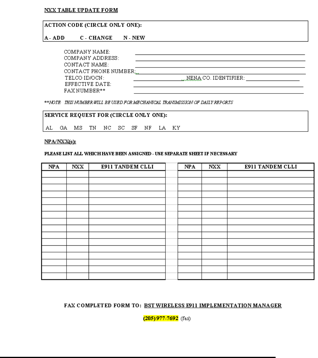
CG-EWCG-001 Wireless E911 Guide
Issue 3, January 6, 2004 TN Database Updates
5.5 NXX Table Update Form
Figure 1 NXX Table Update Form
Page 29

Wireless E911 Guide CG-EWCG-001
TN Database Updates Issue 3, January 6, 2004
5.6 MSAG Formatting
There are basic guidelines for the format of the address on the incoming TN records in order for the TN
record to find an exact match to an existing entry in the MSAG database. TN records which do not match
the MSAG exactly will error back to the Wireless Carrier for resolution and re-transmission of the TN data.
Wireless Carriers must work with the E911 Customer and agree on cell site address formats and to ensure
corresponding entries are present in the MSAG database. Cell site sector location information provided by
some solutions real time during 911 call processing is not validated against the MSAG, although the initial
TN record added to the database must have an MSAG valid address.
An example of an MSAG entry in the E911 database is shown below:
Range Prefix
Directional Street
Name Street Suffix
(Thoroughfare) Post
Directional Community
100-399 N MAIN ST SW CHARLOTTE
The address for the TN record being submitted via file transfer would need to be formatted to match the
MSAG format shown below:
5.6.1 Correct Format
125 N MAIN ST SW CHARLOTTE
The SOIR will be formatted as follows:
House Number = 125
PREFIX DIRECTIONAL = N
STREET NAME= MAIN ST SW (includes street name, street suffix, & post directional)
COMMUNITY = CHARLOTTE
5.6.2 Incorrect Format
125 NORTH MAIN STREET SW CHARLOTTE
125 N MAIN STREET SW CHARLOTTE
125 NORTH MAIN ST SW CHARLOTTE
All of the above examples shown in the incorrect format would have generated an error back to the
Wireless Carrier.
Some other basic rules or guidelines for address format are:
• Avoid using punctuation such as periods, commas, and / or ampersands. Punctuation is only
allowed as part of the street name. (i.e. O’HENRY)
• Standard street suffix (thoroughfare) and/or directional abbreviations must always be used.
Refer to the valid list of standard abbreviations shown in this tab.
Page 30

CG-EWCG-001 Wireless E911 Guide
Issue 3, January 6, 2004 TN Database Updates
5.7 Standard Street Suffix (Thoroughfare) Designations / Directionals
The following table outlines the BellSouth street suffix (thoroughfare) abbreviations.
5.7.1 BellSouth Street Suffix (Thoroughfare) Abbreviations (Table)
Table D BellSouth Street Suffix (Thoroughfare) Abbreviations (Table)
T / F Abbrev Description T / F Abbrev Description
ALY ALLEY LN LANE
ANX ANNEX LOOP LOOP
ARC ARCADE MKT MKT
AV AVENUE MNR MANOR
BDWK BOARDWALK MT MOUNT
BEND BEND MTN MOUNTAIN
BLK BLOCK NK NECK
BLVD BOULEVARD PASS PASS
BR BRANCH PATH PATH
BTM BOTTOM PD POND
BYP BYPASS PK PARK
CIR CIRCLE PKE PIKE
CRES CRESCENT PKWY PARKWAY
CRK CREEK PL PLACE
CRSG CROSSING PLZ PLAZA
CSWY CAUSEWAY PR PIER
CT COURT PROM PROM
CTR CENTER PT POINT
CV COVE PVT DR PRIVATE DRIVE
DR DRIVE RD ROAD
ESPLND ESPLANADE RDG RIDGE
EST ESTATE RDWY ROADWAY
EXPWY EXPRESSWAY ROW ROW
EXT EXTENSION RT ROUTE
- continued -
Page 31

Wireless E911 Guide CG-EWCG-001
TN Database Updates Issue 3, January 6, 2004
Table D BellSouth Street Suffix (Thoroughfare) Abbreviations (Table) (continued)
T / F Abbrev Description T / F Abbrev Description
FRK FORK RUN RUN
FRWY FREEWAY SQ SQUARE
GRDN GARDEN ST STREET
HBR HARBOR STA STATION
HL HILL TER TERRACE
HLS HILLS THRWY THRUWAY
HOLW HOLLOW TR TRAIL
HT HEIGHT TRC TRACE
HTS HEIGHTS TRNPK TURNPIKE
HWY HIGHWAY VLG VILLAGE
ISL ISLAND WAY WAY
JCTN JUNCTION WHF WHARK
LDG LANDING WK WALK
LK LAKE YD YARD
When "Avenue" precedes a street name that is a letter or number, it is not considered a street suffix
designation and is, therefore, spelled in full. Refer to examples shown below. When the name of a street is
an alphabetic character, the word "Street" is spelled in full. Refer to the examples shown below.
Directional words, North (N), South (S), East (E), West (W), North East (NE), North West (NW), South
East (SE), South West (SW) are abbreviated except when used as lettered streets. Refer to the examples
shown below.
Street Examples:
511 1ST 733 33RD 23 STREET A NE
600 1ST STREET 733 N 33RD TER 25 SOUTH RD
411 1ST AV 985 NW 5TH CT 60 NORTHEAST BLVD
512 1ST NE 109 E STREET
622 22ND PL SW 735 AVENUE K
5.8 Standard Location Designations
A portion of the TN data record layout described in this tab includes a data field for specific location
information. This field is not edited on incoming SOIRs for content, however, there are certain format
standards that the PSAP customer is accustomed to seeing on wireline database records. For wireless
Page 32

CG-EWCG-001 Wireless E911 Guide
Issue 3, January 6, 2004 TN Database Updates
data records, the location data field may be used to define the cell site sector geographical service area.
Wireless Carriers should work with the E911 Customer and agree on the TN data record formats including
use of the LOCATION (LOC) data field.
There are four(4) levels of identifiers used for different types of information. Those identifiers are shown
as follows in the appropriate hierarchical level:
Level 1: BLDG, WNG, PIER
Level 2: FLR
Level 3: APT, RM, LOT, SLIP, SUIT, UNIT
Level 4: DES
These identifiers may be used uniquely or combined. The identifiers and associated data cannot exceed the
size limitation of the data field. Some examples are shown below:
EXAMPLE 1: APT 2-B
EXAMPLE 2: BLDG 6 APT 2-B
EXAMPLE 3: FLR 6 SUIT 2-B
EXAMPLE 4: DES NEXT TO POOL
EXAMPLE 5: .25 MI NE OF MAIN ST (wireless example)
5.9 Updating the TN Database
The Wireless Carrier must provide data records for the E911 database as described in this tab. Data
records are validated for proper format and to ensure the address information is defined in the MSAG
database. The TN data record includes a "Function of Change" data field to indicate the type of processing
that should be performed for this record. Processing rules for some of the "Function of Change" data
values are described below:
Function of Change
Data Value: Processing Rules:
IInsert this data record into the database. There must not be another data
record with the same TN (pANI) or calling number in the database or the
insert will fail.
C Change the corresponding record in the database. A data record must
already exist in the database with the same TN (pANI) or calling number.
The entire database record is replaced by the new data record, therefore
the incoming record must have all appropriate data fields populated.
DDelete the corresponding record in the database. A data record must
already exist in the database with the same TN (pANI) or calling number.
EDelete the corresponding record in the Error File. No processing is
performed against the E911 database.
Page 33

Wireless E911 Guide CG-EWCG-001
TN Database Updates Issue 3, January 6, 2004
5.10 Service Order Interface File Specifications
This section describes BellSouth Service Order Interface file specifications and Service Order Interface
Record (SOIR) layouts. BellSouth SOIR layouts resemble the 512 character NENA Version 2 layouts for
Data Exchange with some BellSouth specific differences. Files for updating the BellSouth E911 database
must adhere to the following file specifications:
1. All files contain a single file header record, followed by one or more data records, followed by
a single file trailer record. All records are 512 characters in length. Layouts are described in
this tab.
2. All data must be in ASCII format.
3. All data must be in upper case.
4. Required fields must contain valid data. Required fields are indicated in the layouts with
capitalized field names.
5. Optional fields may be space filled, unless otherwise noted, if data values are not available.
Optional fields are indicated in the layouts with lower case field names.
5.11 SOIR File Data Record Layout
5.11.1 Table: SOIR File Data Record - BellSouth 512 Character Format for Data
Exchange
Page 34

CG-EWCG-001 Wireless E911 Guide
Issue 3, January 6, 2004 TN Database Updates
Table E SOIR File Data Record - BellSouth 512 Character Format for Data Exchange
Sent to PSAP Stored in
Database Field Name Position Bytes Type BellSouth Description
No No FUNCTION
CODE 1 1 AType of activity the record is being
submitted for. Valid entries:
•C- Change
•D- Delete
• I - Insert
•E-Delete Error
• U - Unlock (LNP)
•M- Migrate (LNP)
Yes Yes NPA 2-4 3NThree(3) digit area code of the Calling
Number.
Yes Yes CALLING
NUMBER
(TN)
5-11 7 N Seven(7) digit telephone number of the
Calling Number. For Wireless, pseudo
ANI of PSAPor antenna face receiving
wireless call.
Yes - Only
eight(8)
characters sent
to PSAP.
Yes HOUSE
NUMBER 12 - 21 10 AN House number. The field should be space
filled if no house number is available.
Yes Yes house number
suffix 22 - 25 4 AN House number extension (e.g., 1/2). The
field should be space filled if suffix does
not apply. Do not lead with hyphen.
Yes Yes prefix directional 26 - 27 2 ALeading street direction prefix.The field
should be space filled if no prefix applies.
Valid entries: N, S, E, W, NE, NW, SE,
SW.
- continued -
Page 35

Wireless E911 Guide CG-EWCG-001
TN Database Updates Issue 3, January 6, 2004
Table E SOIR File Data Record - BellSouth 512 Character Format for Data Exchange (continued)
Sent to PSAP Stored in
Database Field Name Position Bytes Type BellSouth Description
Yes - Only 48
characters sent
to PSAP.EX:
Main St NW
Yes - Some
solutions
may change
this data via
dynamic
update
during
911 call
processing.
STREET NAME
STREET
SUFFIX
POST
DIRECTIONAL
28 - 93 66 AN MSAG valid service address of the
Calling Number, PSAP or Antenna
Site. Include street name, street suffix
(i.e.thoroughfare designation) and post
directional. Street Suffixes must conform
to BellSouth MSAG standards; valid
Post Directional entries are: N, S, E, W,
NE, NW, SE, SW.
EX: MAIN ST NW
Yes - Only 18
characters sent
to PSAP.
Yes - Some
solutions
may change
this data via
dynamic
update
during
911 call
processing.
COMMUNITY
NAME 94 - 125 32 AValid service community of the street
name / house number as designated by
the MSAG.
Yes Yes STATE 126 - 127 2 AAlpha postal state abbreviation (e.g., AL,
FL, GA, KY, LA, MS, NC, SC, and TN).
Yes - Value of
G = Wireless
P1 (Sent
to PSAP
as WRLS).
Value of H =
Wireless P2
(Sent to PSAP
as WPH2)
Yes - Only
twenty(20)
characters
stored and
sent to
PSAP.
location 128 - 187 60 AN Additional address information (free
formatted) describing the exact location
of the Calling Number (e.g., APT 718).
- continued -
Page 36

CG-EWCG-001 Wireless E911 Guide
Issue 3, January 6, 2004 TN Database Updates
Table E SOIR File Data Record - BellSouth 512 Character Format for Data Exchange (continued)
Sent to PSAP Stored in
Database Field Name Position Bytes Type BellSouth Description
Yes Yes CUSTOMER
NAME 188 - 219 32 AN Carrier name associated with the Calling
Number.
Yes - Value of
G = Wireless
P1 (Sent
to PSAP
as WRLS).
Value of H =
Wireless P2
(Sent to PSAP
as WPH2)
Yes CLASS OF
SERVICE 220 1 AN Value of:
G=Wireless P1
Value of:
H=Wireless P2
No Yes TYPE OF
SERVICE 221 1 NValue of:
0=Not Non-Pub
3=Non-Pub
No Yes EXCHANGE 222 - 225 4 AN Phone company exchange identifier
for the serving telephone office of the
customer; ALEC and Wireless may be
blank.
Yes - Only
three(3)
characters sent
to PSAP.
Yes esn 226 - 230 5 AN Emergency Service Number associated
with the House Number and Street Name;
this field is blank on input and derived
from the MSAG validation process.
No No MAIN NPA 231 - 233 3 NArea code of the Main Number
associated with the Calling Number. For
wireless, use same value as NPA field.
Yes Yes MAIN
NUMBER 234 - 240 7 N Main telephone number associated with
the Calling Number. For wireless use
same value as Calling Number field.
- continued -
Page 37

Wireless E911 Guide CG-EWCG-001
TN Database Updates Issue 3, January 6, 2004
Table E SOIR File Data Record - BellSouth 512 Character Format for Data Exchange (continued)
Sent to PSAP Stored in
Database Field Name Position Bytes Type BellSouth Description
No Yes order number 241 - 250 10 AN Service order number for the activity
establishing this record.
No Yes EXTRACT
DATE 251 - 256 6 NDate on which the record was created in
the format MMDDYY.
No Yes county identifier 257 - 260 4 AN County Identification code (usually the
FIPS code). Will be blank on input and
derived from MSAG validation process.
Yes Yes COMPANY ID 261 - 265 5 AN Telephone Company Identification code
as assigned through NENA registration
process.
No Yes source identifier 266 1 AN Code which indicates whether data is part
of the initial database creation process or
part of the daily update process.
Daily = Space
Initial Load = C
No Yes zip code 267 - 271 5 AN Postal Zip Code.
No Yes zip +4 272 - 275 4 AN Postal Zip Code Extension.
No No general use 276 - 286 11 AN This field is mutually used by data
exchange partners to pass information
not defined in previous fields.
No Yes CUSTOMER
CODE 287 - 289 3 AN Code used to uniquely identify a
customer. For ICO, ALEC, and Wireless
companies this code can be blank on
input or filled with 999. TN processing
will convert all blanks to 999.
No Yes comments 290 - 319 30 AN Optional notes
- continued -
Page 38

CG-EWCG-001 Wireless E911 Guide
Issue 3, January 6, 2004 TN Database Updates
Table E SOIR File Data Record - BellSouth 512 Character Format for Data Exchange (continued)
Sent to PSAP Stored in
Database Field Name Position Bytes Type BellSouth Description
Yes -
Dynamically
updated in
DB.
Yes -
Dynamically
updated in
DB.
x coordinate 320 - 328 9 AN Longitude / X coordinate.
Yes -
Dynamically
updated in
DB.
Yes -
Dynamically
updated in
DB.
y coordinate 329 - 337 9 AN Latitude / Y coordinate.
No No z coordinate 338 - 342 5 AN Reserved for future use. Structure
elevation.
No No cell identifier 343 - 348 6 AN Reserved for future use. Identification
number indicating a geographic region
of cellular coverage.
No No sector identifier 349 1 AN Reserved for future use. Subset / section
of a cell.
No Yes TAR CODE 350 - 355 6 AN Taxing Area Rate Code. ALEC and
Wireless populate with zeros.
Yes Yes remote call
forward (rcf)
number
356 - 365 10 NRemote Call Forward Number field;
Wireless Providers must send spaces; if
Wireless Provider has dynamic update
interface, or other providers send RCF,
mobile directory number or RCF will be
sent to PSAP following field identifier
of ALT#
No No reserved 366 - 511 146 AN This field is reserved for the processing
company’s use.
No No END OF
RECORD 512 1 AN Always an asterisk (*)
Page 39

Wireless E911 Guide CG-EWCG-001
TN Database Updates Issue 3, January 6, 2004
5.12 SOIR File Header Record Layout
5.12.1 Table: SOIR File Header Record - BellSouth 512 Character Format for Data
Exchange
Field Name Position Bytes Type BellSouth Description
HEADER
INDICATOR 1-5 5 AAlways "UHL "
EXTRACT DATE 6-11 6 NDate formatted as MMDDYY
COMPANY NAME 12-61 50 AN
CYCLE COUNTER 62-67 6 NNew customers start at 000001;
each subsequest file cycle is
incremented by 1 until reaching
999999
county identifier 68-71 4 AN
state 72-73 2 A
general use 74-93 20 AN
release number 94-96 3 N
format version 97 1 N
reserved 98-511 414 AN
END OF RECORD 512 1 Always "*"
5.13 SOIR File Trailer Record Layout
5.13.1 SOIR File Trailer Record - BellSouth 512 Character Format for Data Exchange
Field Name Position Bytes Type BellSouth Description
TRAILER
INDICATOR 1-5 5AAlways "UHL "
EXTRACT DATE 6-11 6NDate formatted as MMDDYY
COMPANY NAME 12 - 61 50 AN
RECORD COUNT 62 - 67 6 NDoes not include header and trailer
record
reserved 98 - 511 414 AN
END OF RECORD 512 1 Always "*"
Page 40

CG-EWCG-001 Wireless E911 Guide
Issue 3, January 6, 2004 TN Database Updates
5.14 Mechanized File Transfer
The Service Order Interface Record (SOIR) is the TN database information that is mechanically
transmitted to INTRADO for inclusion in the E911 database. If the Wireless Carrier data file passes all
validity checks, it will be processed to the E911 database.
PLEASE NOTE: THE PREFERRED METHOD OF DATA TRANSMISSION IS
CONNECT:MAILBOXTM, A PRODUCT OFFERED THROUGH INTRADO. OTHER METHODS
OF DATA TRANSMISSION MAY BE SUPPORTED BY INTRADO. PLEASE COORDINATE
THROUGH THE BST WIRELESS IMPLEMENTATION MANAGER AND INTRADO.
Establishment of CONNECT MAILBOXTM to the INTRADO system will be coordinated through
the BST Wireless E911 Implementation Manager / INTRADO. Once established, support for Connect
MailboxTM will be handled by INTRADO.
Connect Mailbox™ Client for Windows requires the following minimum system requirements:
• Microsoft Windows Version 3.1 or later
• 4MB of Memory
• 2MB of Hard Disk Space (3MB During Installation)
• VGA or Better Card with a Color Monitor
• Hayes Compatible Modem with full Carrier Detect Support
• Utilizes Z Modem as the interface protocol
INTRADO will work with customers that wish to use an alternative client product, so long as that
product supports X-Modem, Z-Modem, or Kermit.
5.15 Mechanized File Confirmations
When an file is sent, a check will be made to determine if any errors exist in the header, data, or trailer
records. If no errors are detected, a positive response will be sent via mechanized fax to the Wireless
Carrier. The positive confirmation detail record is shown below:
Page 41
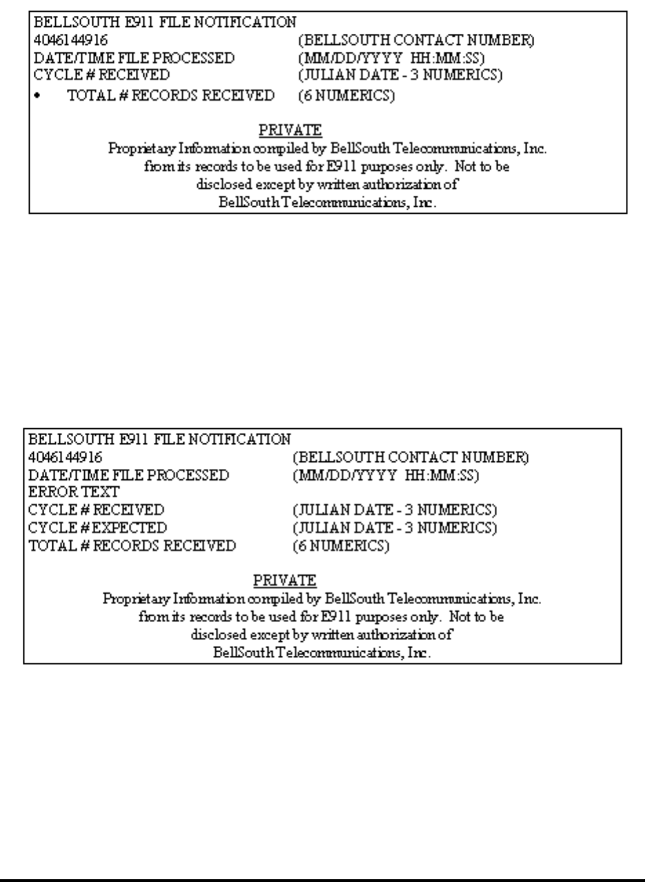
Wireless E911 Guide CG-EWCG-001
TN Database Updates Issue 3, January 6, 2004
If an error is detected, an error confirmation notice will be sent via mechanized fax. The following error
conditions will be detected:
• Record Count Mismatch
• Cycle Mismatch
• Header Record Not Found
• Trailer Record Not Found
The error confirmation notice is shown below:
Page 42

CG-EWCG-001 Wireless E911 Guide
Issue 3, January 6, 2004 TN Errors and Corrective Action
6. TN Errors and Corrective Action
6.1 Overview
This section provides procedures for correcting errors that are generated when updates to the E911
database do not pass database edits. Records that fail the edits will be sent daily in an error report to the
Wireless Carrier. Errors are sorted in TN order and an error code is provided on each error to aid the
Carrier in identifying the erroneous information.
Wireless Carrier error records will not be manually corrected or processed to the E911 database. A
corrective SOIR must be issued to update the TN information in the E911 database and / or to delete the
error record as appropriate. The records which error must be corrected as quickly as possible for the
wireless data to be included in the E911 database.
The Wireless Carrier is expected to resolve the errors by:
• Issuing Address Verification Requests (AVR) to the E911 Coordinator for MSAG changes.
• · Issuing corrective SOIRs within 24 hours of receipt.
6.2 Electronic Error Delivery
Errors are delivered to the Wireless Carrier’s Intrado Connect Mailbox. Confirmation files and Statistics
files with information on error records and records that have processed successfully are generated .
6.2.1 The Confirmation Report
The Confirmation reports list the daily update records that are in error, along with a three-digit error code.
The error code descriptions and corrective action are provided in this tab. (Note: Only records in error
are included on this report. If the record has successfully processed and posted in the ALI database
it will not be included on this report.)
Example of the Confirmation report is shown below. The record layout for electronic errors is in NENA
Version 2 format. There is a three (3) digit error code located at the end of the record in reserved fields
378-380 followed by an "E" to indicate the record is in error.
Page 43
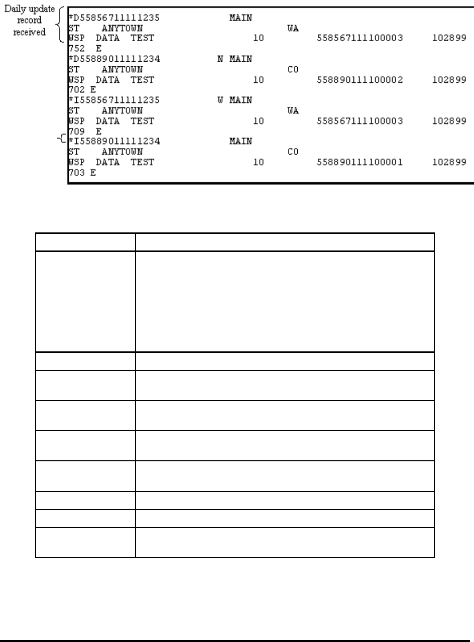
Wireless E911 Guide CG-EWCG-001
TN Errors and Corrective Action Issue 3, January 6, 2004
Table F Confirmation Report Fields and Descriptions
FIELD DESCRIPTION
FUNCTION CODE Valid codes are:
• : I=Insert
• C=Change
• P=Main account delete
• E=Error delete
• U=Unlock
• M=Migrate
NPA Three(3) digit number of Calling Number
CALLING
NUMBER Seven(7) digit number of Calling Number
HOUSE NUMBER House Number. The field should be spaced filled if no house
number is available.
HOUSE NUMBER
SUFFIX House number extension (e.g. /2). The field should be spaced
filled if no suffix applies.
PREFIX
DIRECTIONAL Leading street direction prefix. The field should be spaced filled
if no prefix applies. Valid entries: N, S, E, W, NE, NW, SE, SW
STREET NAME Valid street address of the Calling Number.
STREET SUFFIX Valid street abbreviation.
POST
DIRECTIONAL Trailing street direction suffix. The field should be spaced filled
if no suffix applies. Valid entries: N, S, E, W, NE, NW, SE, SW
- continued -
Page 44

CG-EWCG-001 Wireless E911 Guide
Issue 3, January 6, 2004 TN Errors and Corrective Action
Table F Confirmation Report Fields and Descriptions (continued)
COMMUNITY
NAME Valid service community of the street name/house number as
designated by the MSAG.
STATE Alpha state abbreviation
LOCATION Additional address information (free formatted) describing the
exact location of the Calling Number (e.g. APT 718).
CUSTOMER
NAME Subscriber name associated with the Calling Number.
CLASS OF
SERVICE Value of:
• 8=Moble (pre-Phase 1)
• G=Wireless Phase 1
• H=Wireless Phase 2 (with X,Y)
TYPE OF
SERVICE Value of:
• 0=Not Non-pub or FX
• 1=FX not Non-pub
• 2=Not used
• 3=Non-pub, not FX
• 4=Non-pub, FX
• 5=Not Used
EXCHANGE Local Exchange Carrier exchange identifier for the serving
telephone office of the customer.
MAIN NPA Three(3) digit area code of the Main Number associated with
the Calling Number.
MAIN NUMBER Seven(7) digit telephone number of the Main Number associated
with the Calling Number.
ORDER NUMBER Service order number for the activity establishing this record.
EXTRACT DATE Date for which the record was created in the form MMDDYY
COUNTY ID County Identification Code (usually the FIPS code).
COMPANY ID NENA registered Company Identification Code.
SOURCE ID Indicates whether data is part of the initial database creation
process or part of the daily update process.
• Daily = Space
• Initial Load = C
ZIP CODE Postal Zip Code
ZIP+4 Postal Zip Code Extension
- continued -
Page 45

Wireless E911 Guide CG-EWCG-001
TN Errors and Corrective Action Issue 3, January 6, 2004
Table F Confirmation Report Fields and Descriptions (continued)
GENERAL USE Mutually used by data exchange partners to pass information
not defined in previous fields.
CUSTOMER
CODE Code used to uniquely identify customer.
COMMENTS Optional notes may be displayed at PSAP
X COORDINATE Longitude / X coordinate
Y COORDINATE Latitude / Y coordinate
Z COORDINATE Structure elevation
CELL ID Identification number indicating a geographic region of cellular
coverage.
SECTOR ID Sub set / section of a cell.
TAR CODE Taxing Area Rate Code
RESERVED Positions 356-511 are reserved. Positions 378-380 are used by
Intrado to populate the three(3) digit error code (e.g. 709).
END OF RECORD Always an asterisk (*)
6.2.2 The Statistics Report
The Statistics Report provides information about the processed daily update records The top portion of the
report shows the number of records received, followed by the number of records in error, and the number
of inserts, changes and deletes that were successfully processed. The bottom portion of the report lists all
the valid error codes for the BellSouth region and the number of errors with that error code. Example of
the Statistics Report is shown below.
Page 46
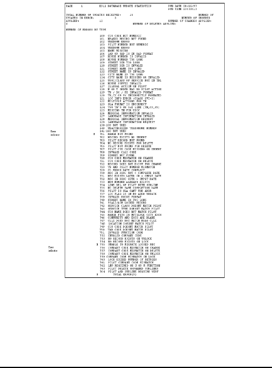
CG-EWCG-001 Wireless E911 Guide
Issue 3, January 6, 2004 TN Errors and Corrective Action
Figure 2 The Statistics Report
6.2.3 Distribution of Daily Reports
Intrado forwards daily reports electronically each business day. The Saturday and Sunday Confirmation
and Statistical reports are included in Monday’s cycle. To retrieve reports after sending a file: (1) return
Page 47

Wireless E911 Guide CG-EWCG-001
TN Errors and Corrective Action Issue 3, January 6, 2004
to Intrado Connect, (2) click on the transfer key, and (3) click on the download key and automatically
retrieve your reports.
6.2.4 TN Error Deletion
When a SOIR is processed, a check is made to determine if an error record exists in the error file with the
same TN on the SOIR. If an error record other than a U (Unlock) or M (Migrate) exists, the error record
will be deleted and the TN will be processed to the E911 Database if the subsequent SOIR is successful. If
an error other than for a U (Unlock) or M (Migrate) SOIR occurs while processing the subsequent SOIR, a
new error record will be written to the error file, thus only one SOIR record should ever be present in the
error file for any given TN.
TN error records requiring deletion will be deleted by issuing a subsequent SOIR with an FOC = "E".
When the FOC = "E" on the subsequent SOIR, the error file will be searched for a match on TN and, if
found, the error will be deleted from the error file. SOIRs sent with a FOC of "E" are used ONLY to
delete a TN from the error file and are not processed to a matching TN embedded record in the E911
database. An example of a situation where an "E" FOC might be used is to delete a TN error record where
the original SOIR had been with an invalid TN.
6.3 Error Codes and Error Descriptions
The following error codes may be generated and sent via fax.
Note: If an error code is received that is not reflected in this guide, please refer to the BellSouth
Wireless E911 Implementation Manager.
Table G Error Codes and Error Descriptions
ERROR DESCRIPTION
100 Customer Code not numeric
101 NPA/NXX not valid
103 Main TN not numeric
105 Name Missing
106 Address Missing
107 House number contains invalid characters
108 House number is too long
109 Street direction is too long
110 Street Direction is invalid
111 Street name is too long
- continued -
Page 48

CG-EWCG-001 Wireless E911 Guide
Issue 3, January 6, 2004 TN Errors and Corrective Action
Table G Error Codes and Error Descriptions (continued)
ERROR DESCRIPTION
112 Street name has invalid characters
113 Community Name is too long
114 Community Name has invalid characters
115 Service class invalid
116 House Number Suffix is too long
120 TN is incorrectly formatted
126 Invalid type of service
701 House number is not in MSAG range
702 Record already exists, insert not allowed
704 Record does not exist for delete
705 Main record not found for delete
709 Street not found in MSAG
710 customer code doesn’t match on change
711 Customer code or street name does not match on delete
712 Record does not exist for change
713 TN and Main Account mismatch
729 Change failed, completion date conflict with disconnect file
730 Insert failed, completion date conflict with disconnect file
731 Change failed, completion date conflict with TN database
732 Record in disconnect with greater completion date
735 Delete failed, record in TN database has same completion date
738 MSAG update caused TN error
739 Invalid house number format
741 Update not allowed; flagged for PS / ALI
751 Invalid Function Code
752 Invalid Company ID
753 No record exists on Unlock
754 No record exists on Lock
755 Unable to migrate a locked record
- continued -
Page 49

Wireless E911 Guide CG-EWCG-001
TN Errors and Corrective Action Issue 3, January 6, 2004
Table G Error Codes and Error Descriptions (continued)
ERROR DESCRIPTION
756 Company Code mismatch on Change
757 Company Code mismatch on Delete
758 Company ID mismatch on Unlock
760 Lock exceeded number of retries
762 U or M Function Required for LNP
781 Error record does not exist for delete
782 Company Code mismatch on error delete
783 Unlock failed; Main account has sublines
792 Record exists with a Company Code mismatch
6.4 Error Code and Corrective Action
Table H Error Codes and Corrective Action
Error Code Error Message Occurs when. . . Corrective Action for . . .
100 Customer Code not
numeric A character other than 999 is sent in
the customer code field of the incoming
record
Issue corrective SOIR for errored TN
showing 999 in the customer code field
101 NPA / NXX not
valid The incoming record contains a NPA /
NXX combination that is not valid E911
database tables
Determine if NPANXX is correct and
• If correct, submit NXX Table
UpdateForm to INTRADO and
resubmit I FOC SOIR for TN
• If incorrect, submit E FOC SOIR
to delete TN error and submit new
SOIR for correct TN
103 Main TN not
numeric The main telephone number shown on
the SOIR is non-numeric Submit E FOC SOIR to delete invalid
TN error and resubmit new SOIR for
correct TN
105 Name missing The customer name field on the incoming
SOIR is blank Issue corrective SOIR for errored TN
with correct customer name
106 Address missing The address field on the incoming SOIR
is blank Issue corrective SOIR for errored TN
with correct MSAG valid street address.
- continued -
Page 50

CG-EWCG-001 Wireless E911 Guide
Issue 3, January 6, 2004 TN Errors and Corrective Action
Table H Error Codes and Corrective Action (continued)
Error Code Error Message Occurs when. . . Corrective Action for . . .
107 House number
contains invalid
characters
The house number on the incoming
SOIR contains characters other than
alpha or numeric.
Determine the correct MSAG valid
house number and submit corrective
SOIR for errored TN
108 House number is too
long The house number on the incoming
SOIR contains too many characters Determine the correct MSAG valid
house number and submit corrective
SOIR for errored TN
109 Street direction is
too long The directional prefix for the street on
the incoming SOIR contains too many
characters
Determine the correct MSAG valid street
name and submit corrective SOIR for
errored TN
110 Street direction is
invalid The directional prefix for the street on
the incoming SOIR contains invalid
characters
Determine the correct MSAG valid street
name and submit corrective SOIR for
errored TN
111 Street name is too
long The street name with thoroughfare and
suffix on the incoming SOIR contains
too many characters
Determine the correct MSAG valid street
name and submit corrective SOIR for
errored TN
112 Street name has
invalid characters The street name for the street on
the incoming SOIR contains invalid
characters
Determine the correct MSAG valid street
name and submit corrective SOIR for
errored TN
113 Community name is
too long The community name on the incoming
SOIR contains too many characters Determine the correct MSAG valid
community name for the street address
and submit corrective SOIR for errored
TN
114 Community
name has invalid
characters
The community name for the street on
the incoming SOIR contains invalid
characters
Determine the correct MSAG valid
street name and community and submit
corrective SOIR for errored TN
115 Service Class
Invalid The incoming record has an invalid class
of service Submit corrective SOIR with valid class
of service
116 House number
suffix is too long The house number suffix on the incoming
SOIR contains too many characters Determine the correct house number
suffix and submit corrective SOIR for
errored TN
120 TN is incorrectly
formatted The TN on an incoming SOIR is not
made up of ten numeric characters. Check the NPANXX in the record for all
numeric and no blanks. Submit E FOC
with NPANXX of errored TN to delete
error record then re-submit SOIR with
correct TN
126 Invalid type of
service The type of service on an incoming
SOIR contains a type of service value
other than 0 or 3
Submit SOIR with valid type of service,
0or3
- continued -
Page 51

Wireless E911 Guide CG-EWCG-001
TN Errors and Corrective Action Issue 3, January 6, 2004
Table H Error Codes and Corrective Action (continued)
Error Code Error Message Occurs when. . . Corrective Action for . . .
701 House number is not
in MSAG range The house number on the incoming
SOIR is not found in the house number
range for the street and community on
the MSAG
Determine if the street range exists in
the MSAG.
• If the house number on the SOIR is
correct but is not in the MSAG, issue
an AVR to the E911 coordinator to
update the MSAG house number
range
• If the house number on the SOIR
is incorrect issue a SOIR with the
correct house number that matches
the MSAG house number range
702 Record already
exists, insert not
allowed
The SOIR has a FOC of I and attempts to
insert a TN into the database that already
exists
Using the image of the existing record
that is sent with the error, determine if
the existing database TN is incorrect or
if the SOIR error is incorrect.
• If the existing database TN is
incorrect, resubmit the SOIR with
a FOC of C to overlay the existing
data with the SOIR data
• If the error record TN is incorrect,
resubmit a SOIR with FOC of E
to delete the errored record and
then resubmit another SOIR for the
correct TN
704 Record does not
exist for delete The TN for the incoming SOIR does not
exist in the database Determine if the account has been
disconnected:
• If disconnected, submit E FOC
SOIR to delete error record
• If error record was issued for invalid
TN, submit E FOC SOIR to delete
error record and resubmit new D
FOC SOIR for correct TN
705 Main account record
not found for delete The main account TN on the incoming
SOIR does not exist in the database Determine if the account has been
disconnected:
• If disconnected, submit E FOC
SOIR to delete error record
• If error record was issued for invalid
TN, submit E FOC SOIR to delete
error record and resubmit new D
FOC SOIR for correct TN
- continued -
Page 52

CG-EWCG-001 Wireless E911 Guide
Issue 3, January 6, 2004 TN Errors and Corrective Action
Table H Error Codes and Corrective Action (continued)
Error Code Error Message Occurs when. . . Corrective Action for . . .
709 Street not found in
MSAG The directional prefix, street name,
community or state on the incoming
SOIR cannot be found in the MSAG
Determine if the street exists in the
MSAG:
• If the prefix, street, community and
state shown on the error record is not
found in the MSAG issue an AVR
to the E911 Coordinator to have the
MSAG updated (Note: Once the
MSAG is updated the error record
will process and load.)
• If the prefix, street, community or
state on the error record is incorrect
and a valid MSAG entry exists,
resubmit a corrective SOIR
710 Customer code
doesn’t match on
change
The customer code shown for the
incoming SOIR doesn’t match the
customer shown on the existing database
record
Determine the correct customer code and
resubmit corrective SOIR with customer
code of 999 or blanks
711 Customer code or
street name does not
match on delete
The customer code, directional prefix,
street name and suffix on the incoming
SOIR does not match the TN in the
database
Using the image of the existing record
that is sent with the error, determine if
the TN in the database should be deleted
• If the existing database TN is should
be deleted, resubmit a correct D
FOC SOIR
• If the existing database TN should
not be deleted and the error record
TN is incorrect, resubmit a SOIR
with FOC of E to delete the errored
record and then resubmit another
SOIR for the correct TN
712 Record does not
exist for change The incoming C FOC SOIR TN is not
found in the TN database Determine if the error record TN is valid:
• If error record TN is valid, no action
is necessary. Processing in the TN
database will change the C FOC to
an I FOC and insert the record.
• If the error record TN is invalid,
resubmit a D FOC SOIR to delete
the TN from the TN database and
then resubmit the C FOC SOIR for
the correct TN
- continued -
Page 53

Wireless E911 Guide CG-EWCG-001
TN Errors and Corrective Action Issue 3, January 6, 2004
Table H Error Codes and Corrective Action (continued)
Error Code Error Message Occurs when. . . Corrective Action for . . .
713 TN and main
account mismatch The main account shown on the incoming
SOIR doesn’t match the main account
shown on the database record.
Submit D FOC on existing database
record to delete TN with different main
account and IFOC with appropriate
changes on corrective SOIR showing the
TN and the main account as the same
number.
729 Change failed,
completion date
conflict with
disconnect file
An incoming SOIR contains a
completion date that is equal to or earlier
that the completion date of the record
that has been deleted
Determine if TN is valid and should be
changed
• If TN is valid submit corrective
SOIR with changes showing a
completion date that is later than the
disconnect date
• If the TN is invalid, submit E FOC
to delete error record
730 Insert failed,
completion date
conflict with
disconnect file
The incoming insert SOIR is for a TN
that has been disconnected and the date
on the insert SOIR is the same or prior to
the date of the disconnected TN.
Determine if the insert record should
have posted prior to the disconnect:
• If yes, issue E FOC SOIR to delete
the error record
• If no, issue resubmit I FOC SOIR
with completion date later than
disconnect date
731 Change failed,
completion date
conflict with TN
database
The incoming change SOIR has a
completion date that is the same or
prior to the date of the TN shown in the
database
Determine the correct sequence of order
activity for the TN:
• If the error record change is correct,
resubmit C FOC SOIR with later
completion date
• If error record is incorrect, submit E
FOC SOIR to delete error record
732 Record in
disconnect with
greater completion
date
The incoming change SOIR has a
completion date that is the same or prior
to the date of the TN in the disconnect
file
Determine the correct sequence of order
activity for the TN:
• If the error record change is correct,
resubmit C FOC SOIR with later
completion date
• If error record is incorrect, submit E
FOC SOIR to delete error record
- continued -
Page 54

CG-EWCG-001 Wireless E911 Guide
Issue 3, January 6, 2004 TN Errors and Corrective Action
Table H Error Codes and Corrective Action (continued)
Error Code Error Message Occurs when. . . Corrective Action for . . .
735 Delete failed, record
in TN database has
same completion
The incoming delete SOIR has a
completion date that is the same
completion date of the TN in the
database
Determine the correct sequence of order
activity for the TN:
• If the error record delete is correct,
resubmit D FOC SOIR with later
completion date
• If error record is incorrect, submit E
FOC SOIR to delete error record
738 MSAG update
caused a TN error This error is not generated as a result of
incoming SOIR but is generated when
INTRADO performs a MSAG update
that deletes the address shown on the TN
record
Contact INTRADO Data Analyst for
resolution.
739 Invalid house
number format The incoming SOIR contain special
or invalid characters for an alpha or
alphanumeric house number
Determine correct house number for TN
and resubmit correct SOIR
741 Update not allowed,
flagged for PS-ALI
/ PinPoint
The TN on the incoming SOIR belongs
to a TN that is shown for a PS / ALI or
PinPoint PBX customer
Submit E FOC SOIR to delete error
record
751 Invalid function
code The incoming SOIR contains an invalid
function code. Valid function codes are:
• C = CHANGE
• D = DELETE
• I = INSERT
• E = DELETE ERROR
• U = UNLOCK
• M = MIGRATE
Resubmit the SOIR with valid function
code
752 Invalid company ID The incoming SOIR has an invalid
NENA ID Resubmit the SOIR with a valid NENA
ID
753 No record exists on
unlock The TN on the incoming unlock SOIR
does not exist in the TN database Determine if the correct TN was sent on
the error record:
• If correct, submit IFOC SOIR for
TN and then resubmit U FOC SOIR
• If incorrect, submit E FOC SOIR to
delete error record
- continued -
Page 55

Wireless E911 Guide CG-EWCG-001
TN Errors and Corrective Action Issue 3, January 6, 2004
Table H Error Codes and Corrective Action (continued)
Error Code Error Message Occurs when. . . Corrective Action for . . .
754 No record exists on
lock The TN on the incoming Migrate SOIR
does not exist in the database. Determine if the error record TN is valid:
• If error record TN is valid, no action
is necessary. Processing in the TN
database will change the M FOC to
an I FOC and insert the record.
• If the error record TN is invalid,
resubmit a E FOC SOIR to delete
the error record
755 Unable to migrate
locked record The TN in the database for the incoming
Migrate SOIR shows a locked status Determine if the error record TN is valid:
• If valid, contact the donor company
to issue an unlock SOIR. The error
record will process once the unlock
SOIR is received.
• If the error record TN is invalid,
resubmit a E FOC SOIR to delete
the error record
756 Company code
mismatch on change The NENA ID on the incoming C FOC
SOIR does not match the NENA ID of
the TN record in the database
Determine if the error record NENA ID
is valid:
• If valid, contact the donor company
to issue an unlock SOIR and
resubmit the SOIR as a M FOC with
the appropriate changed data
• If the error record NENA ID is
invalid, resubmit a E FOC SOIR to
delete the error record
757 Company code
mismatch on delete The NENA ID on the incoming D FOC
SOIR does not match the NENA ID of
the TN record in the database
Determine if the error record NENA ID
is valid:
• If valid, contact the donor company
to issue an unlock SOIR and
resubmit the SOIR as a M FOC
to migrate the record and the a
subsequent D FOC to delete the TN
record
• If the error record NENA ID is
invalid, resubmit a E FOC SOIR to
delete the error record
- continued -
Page 56

CG-EWCG-001 Wireless E911 Guide
Issue 3, January 6, 2004 TN Errors and Corrective Action
Table H Error Codes and Corrective Action (continued)
Error Code Error Message Occurs when. . . Corrective Action for . . .
758 Company code
mismatch on unlock The NENA ID on the incoming U FOC
SOIR does not match the NENA ID of
the TN record in the database
Determine if the error record NENA ID
is valid:
• Contact the donor company to issue
an unlock SOIR
• Resubmit the SOIR as a M FOC to
migrate the record
• Resubmit a subsequent U FOC to
unlock
If the error record NENA ID is invalid,
resubmit a E FOC SOIR to delete the
error record
760 Lock exceeds
number of retries The 755 error for a Migrate order is
unsuccessful for 30 days No action required. INTRADO will
take appropriate action based on dial
tone ownership as shown in NPAC.
Carrier will receive notification of action
taken for the TN on the weekly NPAC
Validation report.
762 NENA ID required
for U or M FOC
SOIR
The incoming U or M SOIR does not
have a valid three(3) to five(5) digit
NENA ID
Submit E FOC to delete SOIR record
from error Resubmit correct U or M
SOIR with valid NENA ID
781 Error record does
not exist for delete The incoming E FOC TN cannot be
found in the error database Verify the TN on the E FOC SOIR record
matches the TN in the error database:
• If TN matches, no action required.
The errored record has been
previously deleted or resolved.
• If TN doesn’t match re-submit E
FOC SOIR for correct TN
782 Company code
mismatch on error
delete
The incoming E FOC TN contains a
NENA company ID that does not match
the NENA ID shown on the TN in the
error database
Verify the NENA ID on the E FOC
SOIR record matches the TN in the error
database:
1. If NENA ID matches, no action
required. The errored record has
been deleted or resolved.
2. If NENA ID doesn’t match
re-submit E FOC SOIR for correct
NENA ID
- continued -
Page 57

Wireless E911 Guide CG-EWCG-001
TN Errors and Corrective Action Issue 3, January 6, 2004
Table H Error Codes and Corrective Action (continued)
Error Code Error Message Occurs when. . . Corrective Action for . . .
783 Unlock failed; main
account has sublines The incoming U FOC TN is in the
database as a main account with other
TNs shown as sublines but no U FOC
was received on the sublines(Note: Since
the main account and Calling number TN
are to be the same TN, this error would
be received only if the TN in the database
had been submitted with a different main
account on a previous SOIR.)
There are two possible corrective actions:
1. If all accounts shown with the main
account are to be unlocked submit a
U FOC for each TN associated with
the original main account.
2. If all accounts are not to be unlocked
submit a D FOC for the existing
subline showing the erroneous main
account and then resubmit an I FOC
for the TN shown with the Calling
number TN as the main account.
792 I FOC record exists
with a different
Company ID
The TN shown on the I FOC SOIR has
a different NENA Company ID than the
existing TN in the database
Verify the TN on the errored record:
• If the TN is correct and is to be
migrated, submit an E FOC on the
error record SOIR and then resubmit
a corrective SOIR with appropriate
record changes as a M FOC
• If the TN on the error record is
incorrect, submit an E FOC to delete
the error record.
6.5 Compiled Error Report
As stated earlier in this tab, it is imperative that all errors must be corrected as soon as possible. Until
an error is corrected, the information will either be in the database incorrectly or not in the database at
all. This could result in E911 calls being directed to the wrong PSAP and having to be transferred to
the appropriate PSAP.
In addition to sending the daily errors, a compiled error report will be forwarded to each Carrier on
a monthly basis in an effort to ensure that the Carrier is aware of all unresolved daily errors. The error
report is sorted in street name order to aid in resolving address errors.
Page 58

CG-EWCG-001 Wireless E911 Guide
Issue 3, January 6, 2004 PSAP Inquiries
7. PSAP Inquiries
7.1 Overview
E911 is a critical emergency service. Therefore, any address condition that interferes with a caller reaching
the appropriate PSAP, and having an accurate display, must be corrected as quickly as possible. For this
reason, the E911 Inquiry Form has been developed as a tool for the PSAP attendants to use in reporting
address problems encountered with the E911 system.
Wireless Carriers will receive E911 Inquiry Forms from the E911 Customer (county) or INTRADO.
Inquiry forms should be logged by the Carrier. A PSAP Inquiry Log form and instructions are provided in
this tab. Once the inquiry has been handled, it should be returned to the originator. If the originator of
the inquiry is unknown, the form should be returned to INTRADO.
The E911 Inquiry Form is divided into five (5) sections. (sample on the following page)
GENERAL: information relating to the PSAP attendant preparing the form
DATABASE: problems relating to the ALI data displayed at the PSAP
REPAIR: problems relating to the network or equipment
COMMENT: input of additional pertinent information
ACTION: response section
Page 59
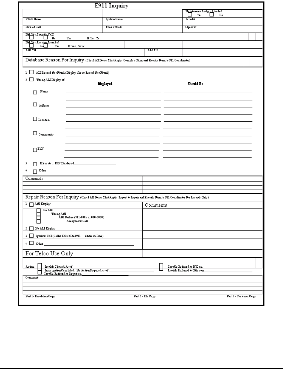
Wireless E911 Guide CG-EWCG-001
PSAP Inquiries Issue 3, January 6, 2004
7.2 PSAP Inquiry Form
Figure 3 PSAP Inquiry Form
Page 60
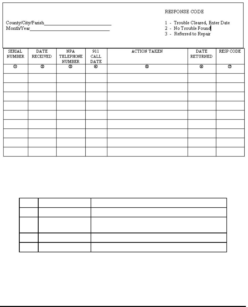
CG-EWCG-001 Wireless E911 Guide
Issue 3, January 6, 2004 PSAP Inquiries
7.3 PSAP Inquiry Log
The following is an example of a PSAP Inquiry Log and instructions for completion:
Figure 4 PSAP Inquiry Log
7.3.1 Instructions for Completing PSAP Inquiry Log
1. Serial Number Enter the serial number assigned by the E911 Customer
2. Date Received Enter the date the Inquiry was received
3. NPA / Telephone
Number Enter the NPA and telephone number being referred on
the Inquiry
4. 911 Call Date Enter the date of the 911 call
5. Action taken Enter the action taken to handle the inquiry
- continued -
Page 61

Wireless E911 Guide CG-EWCG-001
PSAP Inquiries Issue 3, January 6, 2004
- continued -
6. Date Returned Enter the date the Inquiry was returned to the originator
7. Response Code Enter the appropriate response code as follows:
• Trouble Cleared, Enter date
• No trouble found
• Referred to repair
7.4 Inquiry Flow
Inquiry Forms that involve the "Database Reason For Inquiry" will be forwarded to the Carrier for
investigation and resolution. The inquiry form should be logged by the wireless carrier and the disposition
noted. A PSAP Inquiry Log form and instructions are provided in this tab. Once the inquiry has been
resolved, it should be returned to the originator. Inquiries received from INTRADO should be returned to:
FAX: 888-778-7876
INTRADO, Inc.
BellSouth NDSC
1601 Dry Creek Drive
Longmont, CO 80503
7.5 Investigation Procedures
7.5.1 ALI Record Not Found
The Carrier should investigate to determine why the pseudo-ANI record is not in the database. If the TN is
found on the NRF Report, check to see if the TN is a valid pseudo-ANI number. If valid, a SOIR should
be sent to insert the pseudo-ANI TN record. If it is determined that the TN record is in the error file, a
corrective SOIR should be sent to resolve the error. Once resolved, check action: "Trouble cleared as of
(enter the date) and return the form to the originator.
7.5.2 Wrong ALI Display Of:
The E911 Customer will complete the "Should Be" section detailing correct information on the
E911 Inquiry form, when the ALI displays incorrect information. The Carrier should investigate the
discrepancies and make the appropriate database updates as described below.
7.5.3 Address — Community — Location
Investigate as necessary with the E911 Customer to determine the correct address including a check for
MSAG validity. Update the address information for the pseudo-ANI record by submitting a corrected
SOIR with the valid information. Once resolved, check action: "Trouble cleared as of (enter the date)" and
return the inquiry to the originator. If no change is needed to the pseudo-ANI TN record, check action:
"Investigation Completed. No action required as of (Enter the date)" and return the inquiry to the originator.
Page 62

CG-EWCG-001 Wireless E911 Guide
Issue 3, January 6, 2004 PSAP Inquiries
7.5.4 ESN
Investigate as necessary with the E911 Customer to determine the correct address. Update the address
information for the pseudo-ANI TN record by submitting a corrected SOIR with the valid information.
Once resolved, check action: "Trouble cleared as of (enter the date)" and return the inquiry to the
originator. If it is determined that the pseudo-ANI address is correct, check action: "Trouble Referred
to Other on (Enter date)". These Inquiry Forms should be returned to INTRADO for investigation. If it
is determined that a correction in the pseudo-ANI TN record is necessary, INTRADO will contact the
wireless carrier for a new SOIR to be sent.
7.5.5 Misroutes
A misroute indicates the E911 call routed to the wrong PSAP. Routing is determined by the ESN associated
with the matching address record in the MSAG database. Investigate as necessary with the E911 Customer
to determine the correct address. The E911 Customer should be able to assist with identifying the MSAG
valid address and the associated ESN to route the calls to the desired PSAP. Update the address information
for the pseudo-ANI TN record by submitting a corrected SOIR with the MSAG valid information. Check
action: "Trouble cleared as of (enter the date)" and return the inquiry to the originator. If it is determined
that the pseudo-ANI address is correct, check action: "Trouble Referred to Other on (Enter date)". These
Inquiry Forms should be returned to INTRADO for investigation. If it is determined that a correction in the
pseudo-ANI TN record is necessary, INTRADO will contact the wireless carrier for a new SOIR to be sent.
7.6 Blank Forms
Blank Forms may be reproduced locally as needed. An example of a PSAP Inquiry Log follows.
Page 63

Wireless E911 Guide CG-EWCG-001
PSAP Inquiries Issue 3, January 6, 2004
7.6.1 PSAP Inquiry Log
Figure 5 PSAP Inquiry Log
Page 64

CG-EWCG-001 Wireless E911 Guide
Issue 3, January 6, 2004 No Record Found (NRF) Processing
8. No Record Found (NRF) Processing
8.1 Overview
A No Record Found (NRF) condition occurs when a subscriber calls 911 and no database information
exists for the cell site pseudo-ANI telephone number. The purpose of an NRF investigation is to:
• identify the reason a NRF occurred
• take corrective action to update the database as necessary
There are several reasons a record may not be available for retrieval:
• the record may be in the Error File
• the record may not have posted between the time the cell site has been "turned up" and the
time the record is processed and entered into the database
• the update SOIR file transmission may have failed to complete successfully
• the record may not have been sent to be inserted into the database
It is imperative the Wireless Carriers ensure all appropriate pseudo-ANI records are successfully posted to
the E911 database before conducting 911 call testing or turning up service. Wireless 911 calls processed
without corresponding pseudo-ANI records in the database will result in NRFs at the PSAP and manual
investigation by the INTRADO Data Integrity Unit.
8.2 No Record Found (NRF) Processing
Each PSAP in the region is served by a primary ALI processor and secondary ALI processor. These
processors alternate responses to ALI retrieval requests (bids) coming from the PSAP. Therefore, audit
data, including NRF data, is found on the audit files from both the primary and secondary ALI processors.
This data is combined to produce one NRF report.
8.3 No Record Found (NRF) Report Schedule
The NRF report will be generated every day, Sunday through Saturday. This report provides information
about NRFs for investigation. NRF details will appear on the report once the appropriate carrier is
identified.
The following schedule has been developed for the generation of daily NRF reports. The NRF report will
be faxed daily (Monday-Friday) to the appropriate Carrier or data provider.
Fri / Sat / Sun’s NRFs NRF reports distributed on Monday
Monday’s NRFs NRF report distributed on Tuesday
- continued -
Page 65
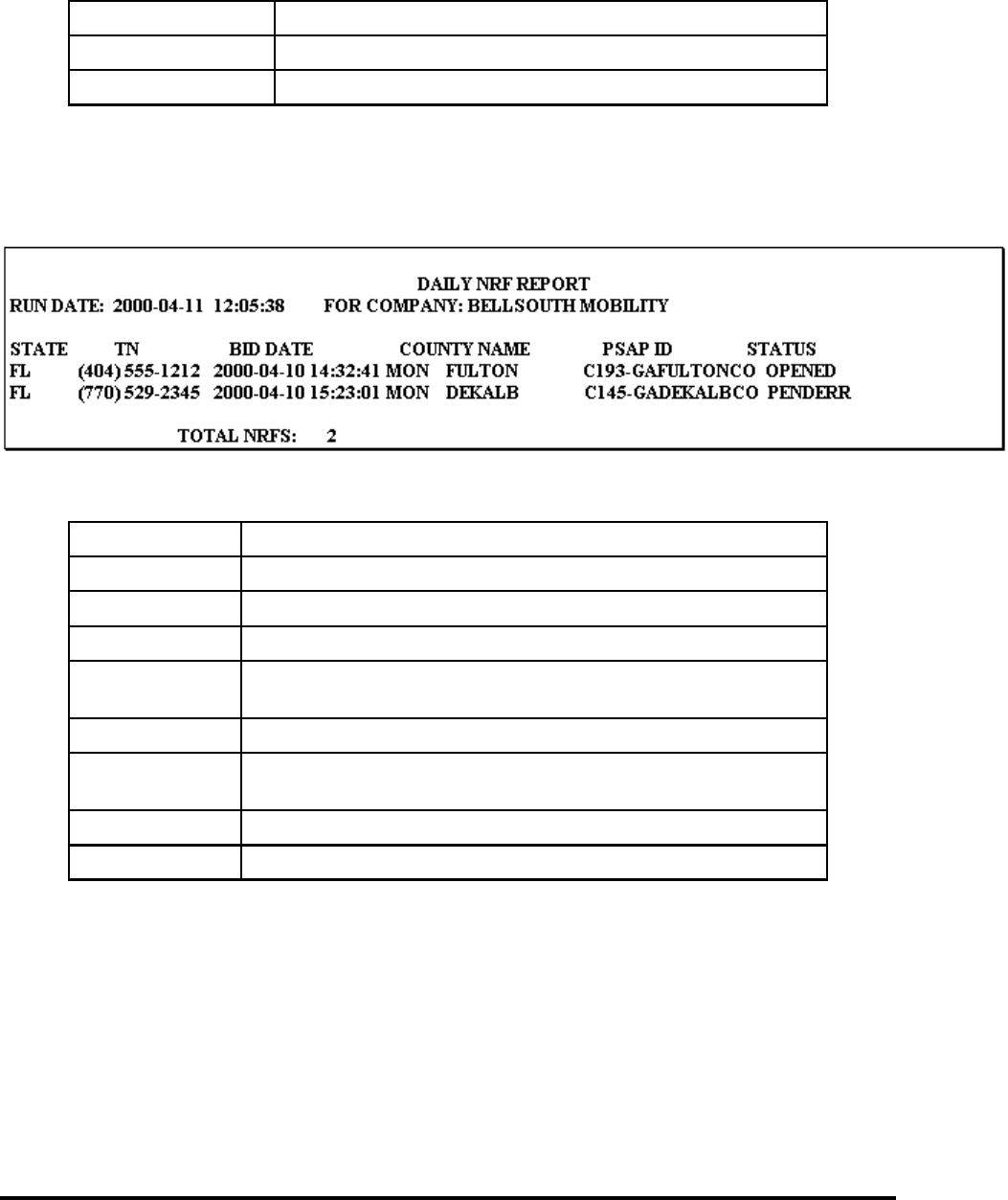
Wireless E911 Guide CG-EWCG-001
No Record Found (NRF) Processing Issue 3, January 6, 2004
- continued -
Tuesday’s NRFs NRF report distributed on Wednesday
Wednesday’s NRFs NRF report distributed on Thursday
Thursday’s NRFs NRF report distributed on Friday
8.4 No Record Found (NRF) Report Layout
The NRF report is separated by Wireless Carrier and by state and sorted by telephone number. A summary
is provided for numbers of NRFs. Following is an example of the NRF report:
The NRF Report will include:
Company: Wireless Carrier name in report heading
Run Date: Date and time of NRF report creation
State: Two(2) character state identifier
TN: Pseudo-ANI number, including NPA, which resulted in NRF
Bid Date: Date, time, and day of week of PSAP query (bid) that resulted in
NRF
County Name: Name of couty for the PSAP receiving NRF
PSAP ID: Two(2) character State identifier, 8 - 10 character PSAP name and
four(4) character PSAP ID of agency that received the NRF
Status: Status of referral: OPENED, PENDERR, REF - LEC
Total NRFs: Total number of NRFs
8.5 NRF Investigation
The Wireless Carrier will only be required to investigate and correct NRFs that are not found in the E911
database or if the record was in the error file at the time of the 911 call.
The Wireless Carrier should:
• Determine if the TN should be in the E911 database.
Page 66

CG-EWCG-001 Wireless E911 Guide
Issue 3, January 6, 2004 No Record Found (NRF) Processing
• If the TN should be in the database, a SOIR should be submitted to insert the TN record or to
resolve an outstanding error in the error file.
• Research why the record was not in the database and take action to prevent further NRF
occurrences.
• Advise INTRADO to close the NRF if the TN has been disconnected or not needed in the
database
When all NRFs on a report have been resolved, the Wireless carrier should file the NRF report and retain
for a period of one(1) year from the date of the 911 call that resulted in the NRF.
Status codes are assigned to each TN on the No Record Found Report. All NRFs are initially assigned as
“OPENED”. The status can be changed by the INTRADO Data Analyst as resolutions are completed.
“CLOSED” will be assigned as soon as the investigation is complete and the E911 database is updated.
The Analyst will assign “REF — LEC” when the investigation cannot be completed in the time frame
which the Analyst began their work. This status would be typical when additional information or action
is required from the Carrier.
The STATUS notations are described as:
Pending — In Error File (PENDERR) — Telephone number was found in the error file and has been
referred to Wireless Carrier for resolution of the error condition.
Referred to LEC (REF — LEC) — The NRF has been referred to the Carrier for resolution. The
Telephone number is not in the TN database or the error file.
If the record is found in the E911 database, the event will be “CLOSED” and the NRF will not be
forwarded to the Carrier. If the TN is found in the error file, the status will be changed to “PENDERR” and
will be included in the NRF report. The Carrier should resolve the outstanding error to prevent further
NRFs from occurring. If the record is not found in the E911 database or error file, the status will be
changed to REF — LEC and the report provided to the Carrier for resolution.
Page 67

Wireless E911 Guide CG-EWCG-001
Issue 3, January 6, 2004
Page 68 - Blank

CG-EWCG-001 Wireless E911 Guide
Issue 3, January 6, 2004 NENA Company Registration Process
9. NENA Company Registration Process
9.1 NENA Cmpany ID Registration Service
Wireless Service Providers and the FCC mandate placed upon them for delivery of location information
and the wireless subscribers callback number generates a need in 9–1–1 service for identification of the
relationship between the telecommunication company and telephone number. This need is driven by
two factors:
Data Base Management
• supports tracking in 9–1–1 data record processing and quality management by both the 9–1–1
service provider and the data source Company
• administration and management of error processes with multiple data providers
Speed of identification by PSAPs
• when a PSAP needs to quickly contact the originating Company for line interrupt, call trace,
and other emergency actions, the typical use of the NPA-NXX for Company identification
will no longer be effective
• an identifier that can be applied to each telephone number record is needed to support
individual telephone number portability
• a Company ID that associates 24 Hour access numbers with each telecommunications
company is needed for the above functions
9.2 Purpose of the NENA Company ID Registration Service
A national Company ID for 9–1–1 service will allow the PSAP to identify the Wireless Carrier serving the
caller, and to determine the 24 x 7 number of that Carrier for emergency contact needs. In the Company
ID database description, (below), each Carrier would identify one ID for each service area supported by
the same 24 x 7 contact number. If the Carrier has a national switching center that would take calls form
PSAPs for emergency assistance, the Carrier would need only one Company ID.
A national 9–1–1 Company ID registration point was recommended by NENA Standards work groups in
1996, and subsequent work has been directed to making this service a part of the NENA Web Site, for
general access. This approach is intended to support standardization of 9–1–1 Company Identifiers, and to
supply a single point of administration for the Company ID file content and update.
Use of the Internet allows telecommunications companies, state, county, city, and PSAP to access and use
the ID information. In addition, the design of this service allows each telecommunications company to
assign multiple IDs, so that individual service areas and 24 hour contact information can be identified.
Note: Use of the previously established NECA code was considered for the above functions.
However, NECA codes are numeric and not as immediately interpretable as are alpha IDs. In
addition, NECA codes do not apply to certain types of 9–1–1 call providing entities, such as
resellers and PBX operators, that are needed in 9–1–1 applications.
Page 69

Wireless E911 Guide CG-EWCG-001
NENA Company Registration Process Issue 3, January 6, 2004
9.3 Use of the Service
For your convenience, NENA has created an online Company Identifier Data Base Input Form that you
can either print out and fill in or you can complete it online, hit the submit button, and you will be
invoiced for the fee. The NENA Web page address is http://www.nena9–1–1.org/companyid. Click
here to access website
If you choose to print it out and fill it in, please send it or fax it to the address / fax below:
FAX: 614–933–0911
Address: 422 Beecher Road, Columbus, OH 43230
An annual fee of $100 will apply for each ID registered by NENA.It is recommended that the Company
Identifier be one that a public safety telecommunicator can readily interpret. A 3–5 character contracted
spelling of the Company name is usually possible. The Company’s choice for an Identifier is likely to be
accepted by NENA, provided that it is not already registered by another Company.
9.4 Instructions
The chosen Company ID code structure should be alpha ONLY using upper case characters. All IDs in the
data base must be unique and the must be limited to 3–5 characters.
The 24 hour by 7 day telephone number should be a number that will allow the safety agencies to contact
the Carrier’s switching support center for line interrupts, call traces, or other emergency contact reasons.
The area covered by the 24 x 7 number may be national, regional, a single state, or other combinations.
Please concisely indicate coverage area in the “Area Supported” field by the use of 2–character state
abbreviations, or “ALL” to indicate all US States. This will allow searching the “Area Supported” field
for those Companies registered in a given area.
Please call NENA at 800–332–39011 if you have any questions.
9.4.1 Input Form
Company Identifier Data Base
Page 70
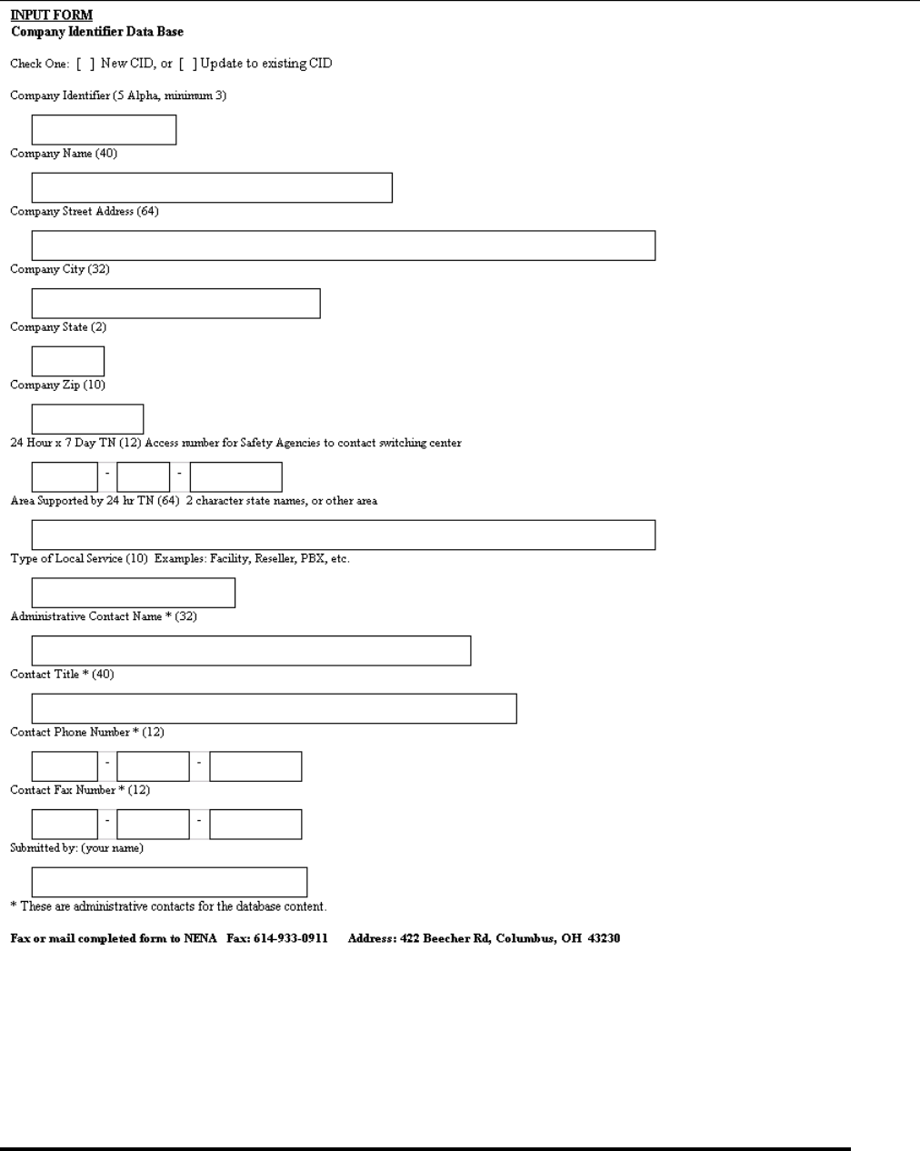
CG-EWCG-001 Wireless E911 Guide
Issue 3, January 6, 2004 NENA Company Registration Process
Figure 6 Input Form
Page 71

Wireless E911 Guide CG-EWCG-001
Issue 3, January 6, 2004
Page 72 - Blank

CG-EWCG-001 Wireless E911 Guide
Issue 3, January 6, 2004 Reconciliation
10. Reconciliation
10.1 Overview
Wireless Carriers or their agents are granted an extract of their E9-1-1 data annually for database
reconciliation. The BellSouth Implementation Manager offering a yearly reconciliation of data sends a
letter and extract request form to each company in the first quarter of the year. This document outlines the
procedures used to request a data extract for the purpose of reconciliation.
10.2 Notification and Scheduling
Complete the "9-1-1 Database Reconciliation Extract Request" form that was attached to the annual
letter and return it to the INTRADO Continuous Improvement Analyst via mail or fax. The INTRADO
Continuous Improvement Analyst will contact you and negotiate an extract date.
10.3
The Wireless Carrier or their agent is responsible for:
• Requesting the Data Extract.
• Reconciling their data by comparing the extract file with data currently maintained within
their carrier database.
• Sending updates as required to the E9-1-1 database via Service Order Interface (SOI)
INTRADO is responsible for:
• Scheduling Data Extracts.
• Determining Extract dates.
Page 73

Wireless E911 Guide CG-EWCG-001
Issue 3, January 6, 2004
Page 74 - Blank

CG-EWCG-001 Wireless E911 Guide
Issue 3, January 6, 2004 BellSouth Wireless E9–1–1/SS7 Interconnection
Guide
A. BellSouth Wireless E9–1–1/SS7 Interconnection Guide
A.1 BellSouth Wireless E-9–1–1/SS7 Interconnection Guide
This document is intended to provide an explanation of how SS7/ISUP trunks can be used for delivery of
Wireless E9-1-1 calls in the BellSouth E9-1-1 serving area.
NOTE: The need to provide and maintain the reliability and integrity of E9-1-1 service is a top priority.
Therefore, deployment/implementation of SS7/ISUP trunking for E9-1-1 is subject to due date negotiation
between BellSouth and any interconnection customer. The migration onto this newer signaling technology
cannot be subject to the Customer Desired Due Date (CDDD) processes.
NOTE:Failure to deploy SS7/ISUP signaling correctly for Wireless E9-1-1 may result in significant service
interruptions or undesirable anomalies, including but not limited to a total inability to complete the call.
NOTE: This document uses acronyms and terms as described in the NENA Master Glossary of E9-1-1
Terms available at http://www.nena9-1-1.org in the NENA Recommended Technical Standards section.
Click here to access this information.
NOTE: All interconnecting carriers need to be familiar with and in compliance with TR 73554 Issue
D, December 2002 (or later), BST GUIDELINES TO TECHNICAL PUBLICATION GR-905-CORE. The
BST CCS Network has its own particular architectural variations and technological capabilities. TR 73554
is a supplement to GR-905.) TR 73554 is available through the appropriate BellSouth Interconnection
Services Account Representative.
Before any new device is connected to the BellSouth Common Channel Signaling Network (CCSN) it
must meet the following two requirements:
1. It must have undergone and passed MTP Level 2 and Level 3 protocol testing by Telcordia or
other suitable independent lab testing facility
2. It must have undergone and passed interoperability testing at the Bellsouth Technology
Assessment Center (BTAC) in Birmingham
This does not include Level 3 protocol testing on new links from known switch types (#5ESS, DMS100,
etc.). SS7 is a mature technology and, over the years, there have been only rare occasions of mismatches
at the Level 3 protocol. These differences have typically been non-traffic affecting differences in timer
settings. For these reasons BellSouth has taken the position that the continued investment in time and Level
3 protocol test equipment would be imprudent. However, any other type of devices (e.g., PBXs, VMS host
machines, packet switching devices, etc.) that are not routinely connected to the network, will be asked to
undergo lab testing with a "standards" lab such as Telcordia or BTAC. We acknowledge there may be some
carriers who don’t undergo such lab testing, and we reserve the right to remove them from our CCSN
without prior notice if their equipment causes us or any of our customers a problem.
A.2 Executive Summary
BellSouth provides Wireless Carriers with connectivity to its Enhanced 9-1-1 Selective Routing network so
they may meet their (FCC mandated) responsibility to provide Enhanced 9-1-1 service to their customers.
Page 75

Wireless E911 Guide CG-EWCG-001
BellSouth Wireless E9–1–1/SS7 Interconnection
Guide Issue 3, January 6, 2004
NENA (National Emergency Number Association) has published a Technical Information Document:
"NENA 05-501 Technical Information Document on SS7 Guidelines for MSC to Selective Router
Connectivity." (available at: http://www.nena9-1-1.org/9-1-1TechStandards/tech_info_docs.htm ). That
document identifies many of the possible call setup parameter options that can occur within the enhanced
9-1-1 network on an SS7/ISUP trunk between a Wireless Service Provider’s MSC and an Enhanced 9-1-1
selective router. The use of SS7 signaling greatly reduces post dial delay and also provides more reliable
ANI delivery when compared to traditional MF signaling. (Throughout this document the term SS7
is to be construed to mean SS7/ISUP signaling.)
As a high level statement, the intent of this BellSouth Wireless E9-1-1/SS7 Interconnection Guide is to list
the call setup parameters shown in the NENA 05-501 TID that are supported by BellSouth, so wireless
carriers can chose the one(s) that best meet their needs.
This documentation will identify, to the Wireless Service Provider, the parameters they need to populate
in their 9-1-1 Signaling System #7 Initial Address Message (SS7 IAM) to provide Phase 1 or Phase 2
E9-1-1 service to their customers.
NOTE: Wireless service providers who desire to take advantage of the SS7 signaling format for E9-1-1
service should contact their BellSouth Account Representative to begin a test and installation plan or to
discuss technical information.
This document identifies only SS7 signaling options supported for E9-1-1 trunk interconnection. SS7
interconnection for E9-1-1 is a service choice made by the wireless carrier, and does not limit, reduce, or
eliminate the current option to deliver E9-1-1 calls to BellSouth using traditional CAMA-MF or FG-D
signaling protocols.
A.2.1 Identified Options:
Section 4 of the NENA 05-501 document describes the various combinations of the call setup parameters.
Three Call Signaling Scenarios representing the four common Wireless E9-1-1 Solutions defined in
Section 3 of the NENA 05-501 TID are as follows:
• Call Signaling Scenario (1) ESRK delivery
• Call Scenario 2, CBN and ESRD Delivery - WITHOUT a hybrid
• Call Scenario 2, CBN and ESRD Delivery - WITH a hybrid
• Call Signaling Scenario (3) CBN, ESRD, and GLP (Geodetic Location Parameter) delivery
NOTE:This BellSouth document further clarifies those NENA 05-501 descriptions by distinguishing
between Call Signaling Scenario (2) CBN and ESRD Delivery without a hybrid architecture at the SR; and
Call Signaling Scenario (2) CBN and ESRD Delivery WITH a hybrid architecture at the SR. The NENA
05-501 authors elected to allow companies (like BellSouth) who offer a hybrid solution to define their
hybrid solution in their own documents. This document does that for BellSouth’s hybrid offering.
A.2.1.1 Call Scenario 1, ESRK Delivery
BellSouth supports the following options as listed in table 4-1 (ESRK Delivery) in "NENA 05-501
Technical Information Document on SS7 Guidelines for MSC to Selective Router Connectivity":
Page 76

CG-EWCG-001 Wireless E911 Guide
Issue 3, January 6, 2004 BellSouth Wireless E9–1–1/SS7 Interconnection
Guide
A1, A2, A3, B1, B2, and B3 are supported using the E911_STD trunk options on the BellSouth Nortel
DMS E9-1-1 Tandem (Referred to as NDET throughout this document.). For all practical purposes these
calls appear to be like wireline calls at the NDET.
A.2.1.2 Call Scenario 2, CBN and ESRD Delivery - WITHOUT a hybrid: (WITHOUT a
hybrid architecture at the Selective Router)
BellSouth supports the following options as listed in table 4-2 (CBN and ESRD Delivery) in "NENA
05-501 Technical Information Document on SS7 Guidelines for MSC to Selective Router Connectivity":
A1, A2, B1, B2, C1, C2, D1, D2 are supported using the E911_STD or WRLS_STD trunk options on
the BellSouth NDET. The strongly preferred, and recommended, trunk option is WRLS_STD because it
is seen as the standard for wireless E9-1-1 calls.
A3, B3, C3, D3 are supported using the E911_STD trunk option only.
E1, E2, F1, F2, G1, G2, H1, H2, I1, I2, J1, J2, K1, K2, L1, L2 are supported using ONLY the WRLS_CLD
option on the NDET.
Option I3 is NOT SUPPORTED on the NDET platform.
NOTE: Call scenario 2 is sometimes called "20 digits to the PSAP". In Phase 1 it was known as Callpath
Associated Signaling (CAS). In Phase 2 (according to J-STD-036-A) it is known as Non-Callpath
Associated Signaling (NCAS).
A.2.1.3 Call Scenario 2, CBN and ESRD Delivery - WITH a hybrid: (WITH a hybrid
architecture at the Selective Router)
BellSouth supports the following options as listed in table 4-2 (CBN and ESRD Delivery) in "NENA
05-501 Technical Information Document on SS7 Guidelines for MSC to Selective Router Connectivity":
A1, A2, B1, B2, C1, C2, D1, D2 are supported using the E911_STD or WRLS_STD trunk options on
the BellSouth NDET. The strongly preferred, and recommended, trunk option is WRLS_STD because it
is seen as the standard for wireless E9-1-1 calls.
A3, B3, C3, D3 are supported using the E911_STD trunk option only.
E1, E2, F1, F2, G1, G2, H1, H2, I1, I2, J1, J2, K1, K2, L1, L2 are supported using ONLY the WRLS_CLD
option on the NDET.
Option I3 is NOT SUPPORTED on the NDET platform.
NOTE: Call scenario 2 is sometimes called "20 digits to the PSAP". In Phase 1 it was known as Callpath
Associated Signaling (CAS). In Phase 2 (according to J-STD-036-A) it is known as Non-Callpath
Associated Signaling (NCAS).
NOTE: Call Scenario 2, CBN and ESRD Delivery - WITH a hybrid is available on ALL of BellSouth’s
(64) NDETs.
A.2.1.4 Call Scenario 3, CBN, ESRD and GLP Delivery: (GLP = Geodetic Location
Parameter)
BellSouth does not support this method at this time due to the inability of the selective router platform and
the MSC platforms to use and/or route on the GLP, or to support ISDN PSAPs in an industry standard
manner.
Page 77

Wireless E911 Guide CG-EWCG-001
BellSouth Wireless E9–1–1/SS7 Interconnection
Guide Issue 3, January 6, 2004
A.2.2 Database Steering Options
The NENA 05-501 document also defines data base steering options that are used to interconnect the
wireless carrier’s network with the BellSouth Enhanced 9-1-1 ALI Database systems. BellSouth will
support the data steering options referred to as "E2" and "E2+", as defined in BellSouth Technical
Reference TR 73610, and in the Intrado technical document "BellSouth SR/ALI to MPC Interface
Specifications for TCP/IP Implementation of TIA/EIA/J-STD-036 E2" (Contact Intrado for the latest issue
supported on BellSouth ALI Data Base systems).
WARNING
The MOST IMPORTANT thing this document can relay is the
following:
IT IS IMPERATIVE THAT ALL PARTIES UNDERSTAND WHAT
IS REQUIRED TO MAKE WIRELESS E9-1-1 WORK PROPERLY
IN AN SS7/ISUP ENVIRONMENT.
Any questions or doubts that the WSPs Network/Translations
Engineer may have, should be brought to the attention of BellSouth
BEFORE proceeding with any provisioning steps. The WSPs
BellSouth Account Representative will arrange to get answers to any
questions from the appropriate BellSouth Network/Translations
E9-1-1 personnel.
The WSP (or their agent) must have the ALI database pre-populated
with records matching the pANIs (ESRD/ESRK) they will use, or the
call will default route, and the PSAP will receive a "no record found"
rather than the expected location information.
Failure to deploy SS7/ISUP signaling correctly for Wireless E9-1-1
may result in significant service interruptions or undesirable
anomalies, including but not limited to, a total inability to complete
the call.
A.3 Scope and introductory text
A.3.1 Wireless E9-1-1 Service Introduction
Wireless E9-1-1 service enables Wireless Service Providers (referred to as WSP or WSPs throughout this
document) to comply with the FCC mandate for providing an Enhanced 9-1-1 service to wireless users that
is somewhat equivalent to the service provided to landline users. FCC Docket 94-102 requires WSPs to
make E9-1-1 service available in two phases. The first phase of 94-102 (Phase I, initially effective April 1,
1998) requires each WSP to provide a Public Safety Answering Point (PSAP) with the caller’s Call Back
Number (CBN), and a "general" location of the caller equivalent to the serving cell site or sector, but only
if the PSAP requests Phase I service in writing and is capable of receiving and utilizing the data.
That general location is represented by a 10 digit number generally known as a psuedoANI (pANI), but
also known as Emergency Services Routing Digits (ESRD) or Emergency Services Routing Key (ESRK)
based on the type of wireless E9-1-1 solution in use. From the BellSouth E9-1-1 Tandem’s point of
Page 78

CG-EWCG-001 Wireless E911 Guide
Issue 3, January 6, 2004 BellSouth Wireless E9–1–1/SS7 Interconnection
Guide
view, this general location number is simply used to determine which PSAP should receive the call.
This document will use the term pANI generically, except where it is more appropriate to use ESRD or
ESRK. Other industry documents specify which precise term is applicable for different situations, but
that distinction is beyond the scope or intention of this document.
The second phase of 94-102 (Phase II, initially scheduled to begin October 1, 2001) requires each WSP to
be able to deliver a wireless 9-1-1 call with Phase I requirements, plus longitude and latitude coordinates
of the caller, accurate to within 150 meters or less, depending on the technology used for location
determination. Originally, WSPs were to begin to make wireless Phase II available by October 1, 2001 to
qualified PSAPs that requested Phase II service by April 1, 2001. After April 1, 2001, the WSPs were to
begin to make Phase II available to qualified PSAPs within six months of a receiving their request for Phase
II service. The FCC modified the original start date in late 2001. Generally speaking, Phase 2 began in late
2002, and it is expected to roll out continually until ubiquitous coverage is provided across all of the USA.
The "BellSouth Wireless E9-1-1 Solution" (aka: WLS911) currently supports Phase I service by allowing a
wireless carrier to send the caller’s CBN and the pANI directly to a BellSouth Nortel DMS E9-1-1 Tandem
switch (NDET) using dedicated FG-D Multi-Frequency signaling trunks. This Solution can also serve
as the underlying architecture to support a WSP in becoming Phase 2 compliant, if they chose to deploy
their own architecture in a manner that accommodates delivery of longitude and latitude coordinates to a
PSAP through the BellSouth ALI database, once they are obtained over an "E2" interface, as described in
J-STD-036-A (BellSouth will also support the modification of E2 generally known as E2+).
In the BellSouth hybrid scenario the CBN and pANI would continue to be transported through the
BellSouth E9-1-1 Network to the PSAP using WLS911, and the longitude and latitude coordinates
would be obtained through the BellSouth ALI database, across an E2 interface provided by the WSP.
BellSouth does not provide the E2 interface transport facilities. There are also other technical/architectural
"Solutions" available in the industry for a WSP to become Phase 1 and/or Phase 2 compliant. Those
solutions are beyond the scope of this document, but BellSouth does permit such alternative Solutions
to be used via our Network.
NOTE: J-STD-036-A describes Phase II standards in greater detail. BellSouth will support E2
functionality in the manner fully described in the Intrado document "BellSouth SR/ALI to MPC Interface
Specifications for TCP/IP Implementation of TIA/EIA/J-STD-036 E2" (Contact Intrado for the latest issue
supported on BellSouth ALI Data Base systems.
Partly due to the E9-1-1 industry’s migration into Wireless Phase II, and also due to other recent and future
(anticipated) technological developments in the E9-1-1 industry in general, BellSouth will begin (in 2004)
to allow the use of Common Channel Signaling (CCS) technology to support Wireless E9-1-1 service.
NOTE: This capability will be thoroughly tested in each instance before it is made available for use.
A.4 Reason for Revision
If this document is revised, this section will summarize the change(s).
A.5 Organization of this Document
This document is to be used in conjunction with the following publications:
Page 79

Wireless E911 Guide CG-EWCG-001
BellSouth Wireless E9–1–1/SS7 Interconnection
Guide Issue 3, January 6, 2004
• TR 73554 Issue D, December 2002 (or later), BST GUIDELINES TO TECHNICAL
PUBLICATION GR-905-CORE (Telcordia document GR-905-CORE specifies the interfaces
required to interconnect out-of-band Common Channel Signaling (CCS) networks that utilize
the Signaling System Number 7 (SS7) protocol provided by a different CCS Network. The
BST CCS Network will have its own particular architectural variations and technological
capabilities. Therefore, the intent of the TR 73554 is to supplement GR-905.)
• NENA 05-501, NENA Technical Information Document on SS7 Guidelines for MSC to
Selective Router Connectivity, Original Issue, October 2002. The NENA 05-501 Technical
Information Document (TID) provides a reference for Wireless Service Providers (WSP) on
the basics of E9-1-1 SS7 translations to the Selective Router (SR). It was issued to address
the obvious need for guidance on SS7 translations between the MSC and the SR. It presents
a broad view of the E9-1-1 related SS7 translations that exist today (2002), and possible
ones for the future.
NOTE: This BellSouth Wireless E9-1-1/SS7 Interconnection Guide document references
configurations detailed in the NENA 05-501 SS7 Guidelines for MSC to Selective Router
Connectivity TID. The two documents should be used together to gain a more clear
understanding of the requirements surrounding using SS7/ISUP supported trunking for
wireless E9-1-1 in BellSouth’s E9-1-1 serving area.
• J-STD-036-A Enhanced Wireless 9-1-1 Phase 2. This Joint Standard has been issued
and approved by the Telecommunications Industry Association and the Alliance for
Telecommunications Industry Solutions, June 2002. This joint standard defines the messaging
required to support information transfer to identify and locate wireless emergency services
callers.
• NENA 03-006, RECOMMENDED STANDARDS FOR E9-1-1 CALL CONGESTION
MANAGEMENT. This NENA document provides additional details regarding how to
establish the proper quantity of Wireless trunks into an E9-1-1 Tandem based on generally
accepted "best practices".
• "BellSouth SR/ALI to MPC Interface Specifications for TCP/IP Implementation of
TIA/EIA/J-STD-036 E2" (Contact Intrado for the latest issue supported on BellSouth ALI
Data Base systems). This is an Intrado document that fully describes the Intrado SR/ALI E2
messaging interface. This is the interface that BellSouth is using!
Specific "Wireless E9-1-1" interconnection requirements for the CCS network interconnection architecture
and the interface protocol for call setup are defined in this BellSouth Wireless E9-1-1/SS7 Interconnection
Guide document. This document will define the interconnection requirements in the BellSouth E9-1-1
Network when using SS7/ISUP in concert with one of the various Wireless E9-1-1 options identified in J
STD-036-A, and in the NENA 05-501 and 03-006 documents.
The MOST IMPORTANT thing this document can relay is the following:
IT IS IMPERATIVE THAT ALL PARTIES UNDERSTAND WHAT IS REQUIRED TO
MAKE WIRELESS E9-1-1 WORK PROPERLY IN AN SS7/ISUP ENVIRONMENT.Any
questions or doubts that the WSPs Network/Translations Engineer may have, should be brought to
the attention of BellSouth BEFORE proceeding with any provisioning steps. The WSPs BellSouth
Account Representative will arrange to get answers to any questions from the appropriate BellSouth
Network/Translations E9-1-1 personnel.
Page 80

CG-EWCG-001 Wireless E911 Guide
Issue 3, January 6, 2004 BellSouth Wireless E9–1–1/SS7 Interconnection
Guide
The WSP (or their agent) must have the ALI database pre-populated with records matching the pANIs
(ESRD/ESRK) they will use, or the call will default route, and the PSAP will receive a "no record found"
rather than the expected location information.
A.6 Wireless CCS Network Interconnection Architecture
A.6.1 General Interconnection Information
Signaling System 7 - Common Channel Signaling using ISDN User Part protocol (SS7/ISUP) for Wireless
E9-1-1 is only supported for Type 2C trunks (interconnected directly to a BellSouth E9-1-1 tandem
switch) as defined in GR-145-CORE. The Type 2C trunks shall be dedicated for Wireless E9-1-1 traffic.
There will always be a minimum of two trunks per trunk group. Ideally, they should be provisioned in
a diverse manner so that a single network fault or incident would not render both trunks inoperable. In
sizing the new SS7/ISUP TG, Wireless Network Planners should build toward providing a P.01 Grade
Of Service (GOS) (see NOTE below).
NOTE:
The NENA document, NENA 03-006, RECOMMENDED PROCEDURES FOR E9-1-1 CALL
CONGESTION MANAGEMENT provides additional details regarding how to establish the proper
quantity of Wireless trunks into an E9-1-1 Tandem based on generally accepted "best practices". ( 03-006
is pending publication on the NENA web site at http://www.nena9-1-1.org as of March 25, 2003)
If a WSP elects to provide direct MF trunks to be used as backup in the event of an SS7 failure, BellSouth
can support such an arrangement. If MF backup is used, the quantity of MF trunks will be determined by
Wireless Network Planning practices, but in no case will it be less than two trunk members per Trunk Group
(TG). Since CAMA-MF only delivers a 7 digit pANI, CAMA-MF Trunk Groups are to be provisioned on a
per NPA basis. FG-D MF signaling allows for delivery of a full 10 digit pANI number, along with a full 10
digit CBN, so FG-D MF Trunk Groups can be provisioned to carry multiple NPAs as long as all default
routed calls should route to the same PSAP. CAMA-MF requires NPA specific trunk groups so the NDET
can "build" a 10 digit pANI upon receipt of only 7 digits across the NPA specific trunk group.
All trunk groups (primary and back-up) must take into account that only ONE default PSAP can be
associated with an E9-1-1 Trunk Group. It is imperative that the Wireless Network Planner keep this in
mind when determining how many trunk groups will be needed for service in any given area.
THAT DECISION CAN HAVE SIGNIFICANT IMPACT ON PSAPs.
As mentioned above, when sizing the new SS7/ISUP TG, Wireless Network Planners should build toward
providing a P.01 GOS. The size of the backup MF TGs shall be a minimum of two, but otherwise may
not necessarily achieve a P.01 GOS, since they are not expected to be frequently called upon. They are
after all - ONLY INTENDED FOR BACKUP!
A.6.2 Wireless Phase 1 vs. Phase 2
It is VERY important that all parties understand that differences of opinion (currently) exist in regard to
the meaning of certain terms used in the Wireless E9-1-1industry at large. Most are just slight nuance
differences, but if two or more people use the same term to mean different things it causes confusion. This
section will attempt to clarify how BellSouth interprets certain Phase 1 and Phase 2 terms, especially in
Page 81

Wireless E911 Guide CG-EWCG-001
BellSouth Wireless E9–1–1/SS7 Interconnection
Guide Issue 3, January 6, 2004
regard to how they are used in this document. There may be significant impact to Wireless E9-1-1 service
if the Wireless Engineer fails to understand these differences during establishment of initial interconnection
using SS7/ISUP for wireless E9-1-1.
Generally speaking, the term CAS (Callpath Associated Signaling) means the same thing in Wireless
Phase 1 and Phase 2. In each case, ALL of the FCC mandated data is carried directly from the WSPs
MSC through the BellSouth E9-1-1 Tandem to the PSAP. In Phase 1, CAS includes two (significant)
data elements, the CBN and the pANI. In Phase 2, CAS includes those two elements as well as the
longitude/latitude coordinates of the caller (aka: x, y) when they dialed 9-1-1 on their wireless device.
Phase 2 CAS requires SS7/ISUP between the MSC and the BellSouth E9-1-1 Tandem, and ISDN to the
PSAP. As of 3Q2002 Phase 2 CAS is NOT supported in BellSouth. (ISUP Initial Address Message
Parameter Contents for CAS are fully described in J-STD-036-A, Annex-D, Section D.1.3)
In Phase 1, NCAS includes two (significant) data elements: the pANI and the CBN. In Phase 1 NCAS,
ONLY the pANI is sent directly from the WSPs MSC through the BellSouth E9-1-1 Tandem to the PSAP
(with the callpath). The CBN is added to the existing pANI record in the BellSouth ALI-DB by the WSP
or their agent during call setup, using an out-of-band signaling path (hence NCAS). The updated pANI
ALI record including the CBN & cell/sector address data is delivered to the PSAP through the BellSouth
ALI database using the BellSouth Standard ALI format. (The various NCAS architectures are beyond the
scope of this document. See J-STD-034 and each NCAS vendor’s own documents for details.)
In Phase 2, NCAS includes those same two (significant) data elements as well as the longitude/latitude
coordinates of the caller when they dialed 9-1-1 on their wireless device (and potentially can include
updated data upon demand). However, in Phase 2, NCAS (as defined in J-STD-036-A, Annex-D,
Section D.1.2) includes BOTH the CBN and the pANI being sent directly from the WSPs MSC through
the BellSouth E9-1-1 Tandem to the PSAP. In this instance the PSAP obtains the longitude/latitude
coordinates through the BellSouth ALI database (using the BellSouth Extended ALI format) via the
WSPs E2 interface. (The various E2 interface architectures are beyond the scope of this document. See J
STD-036-A and Intrado’s "BellSouth SR/ALI to MPC Interface Specifications for TCP/IP Implementation
of TIA/EIA/J-STD-036 E2" for details).
In Phase 2 there is an alternative method of data delivery that J-STD-036-A refers to as Wireline
Compatibility Mode (WCM), which ONLY sends the pANI (ESRK) directly from the WSPs MSC
through the BellSouth E9-1-1 Tandem to the PSAP (Sounds like Phase 1 NCAS doesn’t it? Hence the
terminology confusion!). In WCM the CBN and the longitude/latitude coordinates are added to an existing
pANI record in the BellSouth ALI-DB during the call by the WSP or their agent using an out-of-band
signaling path defined as an E2 interface. An updated Phase 2 compliant pANI ALI record including the
CBN, cell/sector address data and longitude/latitude coordinates is delivered to the PSAP through the
BellSouth ALI database using the BellSouth Extended ALI response format. If the x, y coordinates of
the caller are unknown at the time the updated pANI ALI record is created, the WSP (or their agent) is
expected to fall back to a Phase 1 compliant record that would include the CBN & cell/sector address data.
(The E2 interface architecture and operations are beyond the scope of this document. See J-STD-036-A,
and Intrado’s "BellSouth SR/ALI to MPC Interface Specifications for TCP/IP Implementation of
TIA/EIA/J-STD-036 E2" for details.)
In BellSouth there is another alternative method of data delivery that is structured upon the J-STD-036-A
NCAS Solution in Phase 2, or on J-STD-034 CAS in Phase 1. In either case it is a 20 digits to the PSAP
type solution. However, this 20 digit solution can be used between the MSC and the NDET even if the
PSAP is not capable of receiving 20 digits from the NDET. This is accomplished by using the BellSouth
Page 82

CG-EWCG-001 Wireless E911 Guide
Issue 3, January 6, 2004 BellSouth Wireless E9–1–1/SS7 Interconnection
Guide
Wireless E9-1-1 Solution (WLS911), a Hybrid architecture functional in both Phase 1 and Phase 2
environments. WSPs should see their BellSouth account team for details on how the WLS911 Solution
may be of value in their overall architecture plans.
A.7 Interface Protocol for Wireless Call Setup when using SS7/ISUP signaling.
A WSP choosing to interconnect with SS7 trunks using ISUP signaling in support of delivery of
Wireless E9-1-1 calls shall comply with one of the following three signaling options available in the
BellSouth E9-1-1 Network. On the BellSouth NDET switches the options are known as "WRLS_STD"
or "WRLS_CLD" or "E911_STD". Any one of these three can be supported on the BellSouth NDET
switches on a per incoming trunk group basis. (They would of course be known by other nomenclature
designations on various Wireless switches.)
NOTE: The WRLS_STD signaling option is used when the pANI is located in the Generic Digits (GDP)
Parameter. Calling Party Number is used as the callback number. Charge Number is ignored by the NDET.
This is the industry standard for wireless calls on the NDET.
The WRLS_CLD signaling option is used when the pANI is located in the Called Party Number parameter,
instead of the digits 9-1-1. Calling Party Number is used as the callback number. Charge Number is
ignored by the NDET. Generic Digits (GDP) Parameter IS NOT ALLOWED!
Depending on which signaling option is chosen, the WSP will send an Initial Address Message (IAM)
containing the following parameters when sending a wireless E9-1-1 call to a BellSouth E9-1-1 tandem:
• Calling Party Number Parameter
• Called Party Number Parameter
• Generic Digits (GDP) Parameter (NOT allowed if the WSP uses WRLS_CLD)
• Charge Number Parameter
NOTE: Although Charge Number Parameter is allowed as an optional parameter, it is ignored
by the NDET when using either of the WRLS_xxx signaling options.
• Calling Party Category Parameter
• Originating Line Information Parameter Calling Party Number Parameter
A.7.1 Calling Party Number
The Calling Party Number parameter value is variable depending upon which trunk group signaling option
is being used. If the intention is to achieve Wireline Compatibility Mode (using E911_STD), the Calling
Party Number parameter shall contain the pANI that will be used for Selective Routing, and will be sent to
the PSAP to retrieve additional call data via the ALI database path. Otherwise, in either of the WRLS_xxx
signaling options the Calling Party Number parameter shall contain the caller’s CBN (or a number being
used as a substitute when the CBN is unknown).
The wireless carrier shall specify the contents of the Calling Party Number (i.e., the CBN or a pANI) at
the time the trunk group is ordered (via their BellSouth account team using form RF-1004-WS). Once a
trunk group is provisioned, the wireless carrier shall adhere to their choice (i.e., a trunk cannot signal the
CBN for one call and a pANI for another call).
Page 83

Wireless E911 Guide CG-EWCG-001
BellSouth Wireless E9–1–1/SS7 Interconnection
Guide Issue 3, January 6, 2004
A.7.2 Calling Party Number Parameter
Calling Party Number is a required parameter in the IAM. The Called Party Number parameter
value is variable depending upon which trunk group signaling option is being used. In any case it shall
either contain the digits "911" or a pANI.
The Called Party Number parameter includes the digits "911" when the pANI is provided in the Generic
Digits Parameter (WRLS_STD signaling option), or when the Calling Party Number contains the pANI
(E911_STD for Wireline Compatibility Mode).
The Called Party Number parameter contains the pANI when the Generic Digits Parameter is not used, but
Wireline Compatibility Mode is not desired (WRLS_CLD signaling option). The need to use WRLS_CLD
may be a result of a situation where the WSP switch cannot support a GDP parameter. In that case the
pANI would appear in the Called Party Number parameter. If a WSP switch can support a GDP, and if
Wireline Compatibility Mode is not desired, then the GDP is the recommended place to put the pANI
(WRLS_STD signaling option).
The wireless carrier shall specify the contents of the Called Party Number (i.e., the digits "911" or a pANI)
at the time the trunk group is ordered (via their BellSouth account team using form RF-1004-WS). Once a
trunk group is provisioned, the wireless carrier shall adhere to their choice (i.e., a trunk cannot signal the
digits "911" for one call and a pANI for another call).
Called Party Number is a required parameter in the IAM.
A.7.3 Generic Digits Parameter & GDP Type
The Generic Digits Parameter (if required) shall contain a pANI. The "type of digits" field in the Generic
Digits Parameter shall be coded 01101 (decimal 13) for cell site and sector identification. A Generic Digits
Parameter is conditionally required in the IAM.
A Generic Digits Parametershall be included in the IAM when a wireless carrier chooses to send the
digits "911" in the Called Party Number parameter (WRLS_STD signaling option). If a WSP switch can
support a GDP, and if Wireline Compatibility Mode is not desired, then the GDP is the recommended
place to put the pANI.
A GDP shall NOT be included in the IAM if the Calling Party Number or the Called Party Number
parameter contains the pANI.
The wireless carrier shall specify whether a Generic Digits Parameter will be included in the IAM at the
time the trunk group is ordered (via their BellSouth account team using form RF-1004-WS). Once a trunk
group is provisioned, the wireless carrier shall adhere to their choice (i.e., a trunk cannot include a GDP
for one call and not for another call).
Generic Digits Parameter is a conditionally required parameter in the IAM.
In all cases where GDP is used, "type of digits" must equal "13". Delivery of a pANI in a GDP that
isn’t type 13 will not work as intended.
Page 84

CG-EWCG-001 Wireless E911 Guide
Issue 3, January 6, 2004 BellSouth Wireless E9–1–1/SS7 Interconnection
Guide
A.7.4 Charge Number Parameter
If present, the Charge Number parameter shall contain the caller’s CBN or the non-dialable callback
number, or in Wireline Compatibility Mode it shall contain the pANI. Charge Number is an optional
parameter in the IAM.
Charge Number is an optional parameter in the IAM.
NOTE: Charge Number Parameter is ignored by the NDET when using either of the WRLS_ xxx
signaling options.)
A.7.5 Calling Party Category Parameter (CPC, aka: CPCat)
The Calling Party Category parameter shall be coded as 11100000 (decimal 224) for "emergency service
call".
Calling Party Category is a required parameter in the IAM.
NOTE:
The Calling Party Category parameter encoding "emergency service call" is not required on all E9-1-1
tandem switches and may be waived in some instances. WSPs seeking to waive this requirement should
consult their BellSouth representative. See Attachment "A" for details
A.7.6 Originating Line Information Parameter
For call scenarios #2, and #3 (with or without a hybrid architecture at the Selective Router), the Originating
Line Information parameter shall be coded either as 00111101 (decimal 61) for "cellular services (type1),"
00111110 (decimal 62) for "cellular services (type2)," or 00111111 (decimal 63) for "cellular services
(roaming)." The OLI parameter carries the II digits defined by the NANP administrator. The OLI
parameter and the II values can be found in T1.113 (ANSI ISUP standard). Telcordia has also listed the
wireless II values (61, 62, and 63) in the E9-1-1 SS7 generic requirements document GR-2956.
For call scenario #1, (WCM) the Originating Line Information parameter shall be coded either as 00
(POTS).
Click here to view call scenarios.
Originating Line Information is a required parameter in the IAM.
The Originating Line Information parameter is not required on all E9-1-1 tandem switches and may
be waived in some instances.
NOTE:
WSPs seeking to waive this requirement should consult their BellSouth representative. See Attachment
"A" for details. BellSouth NDETs running software NA016 or higher will require the OLI parameter IF
AIN OFF-BOARD SELECTIVE ROUTING IS BEING USED.
Page 85

Wireless E911 Guide CG-EWCG-001
BellSouth Wireless E9–1–1/SS7 Interconnection
Guide Issue 3, January 6, 2004
A.8 Cross Reference Tables to J-STD-036-A
The intention of this section is to provide a method for a WSP to assess which type of BellSouth supported
SS7/ISUP signaling option can best fit their needs. Each decision MUST take into account the capability
of the WSPs MSC and the capability of the PSAP CPE, and may be impacted by the type of ALI steering
options involved.
The following pages in this section represent the different interconnection scenarios that are described in
J-STD-036-A for Wireless E9-1-1 Phase 2.
A.8.1 Wireline Compatibility Mode (NDET uses signaling option E911_STD)
If the WSP will be using a Wireless E9-1-1 Phase 1 Non Callpath Associated Signaling (NCAS) Solution,
as described in J-STD-034 or Wireless E9-1-1 Phase 2 Wireline Compatibility Mode, as described in
J-STD-036-A to deliver the Call Back Number (CBN) and/or x, y coordinates to the PSAP via the
ALI database, Table "A" below describes an acceptable interconnection method (known as Wireline
Compatibility Mode in , as described in J-STD-036-A). In this interconnection method ONLY the pANI is
sent into the BellSouth NDET, directly from the WSPs MSC over dedicated trunks. The pANI is used by
the NDET for selective routing, and then the pANI is sent to the PSAP the same way ANI would be on a
landline call. That may be as an 8 or 10 digit number, depending on the capability of the PSAP CPE.
The NCAS or WCM Solution provider is expected to create a record in the BellSouth ALI database that
will contain the CBN (among other data normally included by the NCAS provider, which may or may not
also include Phase 2 data). That activity is beyond the scope of this document.
Extracted in part from Annex D: of J-STD-036-A, clarified for use in BellSouth.
Table "A" ISUP Initial Address Message Parameter Contents for Wireline Compatibility Mode (ESRK).
In this mode only the ESRK is sent as the ANI over dedicated trunks to the Selective Router because the
trunk between the Selective Router and the PSAP supports transport of only one 7/10 digit number.
Orreq Parameters ISUP Parameters Value
Digits(Dialed) Called party number (911) (see Note 1 below)
MDN (aka: CBN) Calling party number (see Note 2
below) ESRK
DMH_BillingDigits Charge Number (see Note 2
below) ESRK
GenericDigits Generic digits parameter (see Note
3 below) NOT ALLOWED (see Note 3
below)
GeographicPosition Calling geodetic location n/a
n/a Originating Line Information
(OLI) If included, use value 00
(POTS)
NOTES:
Page 86

CG-EWCG-001 Wireless E911 Guide
Issue 3, January 6, 2004 BellSouth Wireless E9–1–1/SS7 Interconnection
Guide
1. For an ESC, the ISUP Called Party Number parameter shall only be populated with the
digit value "911".
2. The Calling Party Number MUST be included in the IAM message. The Charge Number may
also be included in the IAM, but if so it MUST be the SAME as the Calling Party Number.
3. The Generic digits parameter SHALL NOT be included in the IAM.
A.8.2 ISUP Initial Address Message Parameter Contents for NCAS (NDET uses
signaling option WRLS_STD, because MSC can support GDP)
(NCAS as described in J-STD-036-A, Annex-D, Section D.1.2)
As this (NDET) signaling option’s name implies, this should only be used on trunks handling wireless
traffic exclusively, and is the industry standard for wireless calls (on an NDET). This option uses the pANI
in the Generic Digits parameter to route the call and uses the Calling Party Number Parameter as the
callback number. If the WSP will be using a Non Callpath Associated Signaling (NCAS) Solution (as
described in J-STD-036-A, Annex-D, Section D.1.2) that intends to deliver the Call Back Number (CBN)
and the pANI to the PSAP via the trunk between the Selective Router and the PSAP, Table "B" below
illustrates an acceptable interconnection method. In this interconnection method BOTH a pANI (ESRD)
and the CBN (aka: MDN) are sent in the SS7/ISUP IAM directly from the WSPs MSC over dedicated
trunks into the BellSouth NDET. The pANI is used by the NDET for selective routing, and then the CBN
and the pANI are sent to the PSAP using Enhanced MF signaling (E-MF). This is of course dependant on
the ability of the PSAP CPE to receive and utilize E-MF. As of 3Q2003 no PSAPs in BellSouth’s E9-1-1
service area are using E-MF, but many may migrate toward it beginning in 4Q2003 or 1Q2004.
When using this interconnection method the NCAS Solution provider might still create a record in the
BellSouth the ALI database containing the pANI &/or the CBN (among other data normally included by
the NCAS provider, which may or may not also include Phase 2 data). That is beyond the scope of this
document.
See Table “B” below.
See prior page for an explanation of when this type of interconnection is acceptable.
NDET uses signaling option WRLS_STD, because MSC can support GDP)
Extracted in part from J-STD-036-A, Annex-D, Section D.1.2, but clarified for use in BellSouth
Table "B" ISUP Initial Address Message Parameter Contents for Phase 2 NCAS.
In this mode both an ESRD and the MDN are sent in the IAM, assuming that the trunk between the
Selective Router and the PSAP supports transport of at least two 7/10-digit numbers.
NOTE:
This 20 digit solution can be used between the MSC and the NDET even if the PSAP is not capable of
receiving 20 digits from the NDET. This is accomplished by using the BellSouth Wireless E9-1-1 Solution
(WLS911), a Hybrid architecture functional in both Phase 1 and Phase 2 environments. WSPs should see
Page 87

Wireless E911 Guide CG-EWCG-001
BellSouth Wireless E9–1–1/SS7 Interconnection
Guide Issue 3, January 6, 2004
their BellSouth account team for details on how the WLS911 Solution may be of value in their overall
architecture plans.
Orreq
Parameters UP Parameters Value
Digits(Dialed) Called party number (see Note 1
below) 911
MDN (aka: CBN) Calling party number (see Note 3
below) CBN or the non-dialable number
used in lieu of a real callback
DMH_BillingDigits Charge Number (see Note 3 below) CBN or the non-dialable number
used in lieu of a real callback (see
Note 3 below)
GenericDigits Generic digits parameter (see Note 2
below) ESRD
GeographicPosition Calling geodetic location n/a
n/a Originating Line Information (OLI) If included, use value 61 OR 62
NOTES:
1. 911 is used as the Called party number. In BellSouth the MSC MUST use dedicated trunks to
the Emergency Services Network Entity (ESNE) to route the Emergency Services Call (ESC).
2. The Type of Digits field within the Generic Digits Parameter should be set to 01101 (decimal
13) to indicate Location Identification Number .
3. The Calling Party Number MUST be included in the IAM message. The Charge Number may
also be included in the IAM, but if so it MUST be the SAME as the Calling Party Number.
Although Charge Number Parameter is allowed as an optional parameter, it is ignored by the
NDET when using either of the WRLS_xxx signaling options.
A.8.3 ISUP Initial Address Message Parameter Contents for NCAS (NDET uses
signaling option WRLS_CLD because MSC cannot support GDP)
As this signaling option’s name implies, this should only be used on trunks handling wireless traffic
exclusively. This type of signaling (WRLS_CLD) looks for the pANI in the Called Party Number
parameter rather than the Generic Digits Parameter. It uses the Calling Party Number parameter as the
callback number. Signaling type WRLS_CLD assumes the Called Party Number is always the pANI. This
signaling option (WRLS_CLD) IS NOT TO BE USED IF WIRELINE COMPATIBILITY MODE
IS DESIRED (use E911_STD instead). The need to use WRLS_CLD is assumed to be the result of a
situation where the WSP’s MSC switch cannot support a GDP parameter. In that case the pANI would
appear in the Called Party Number parameter, as long as WCM is NOT desired.
Page 88

CG-EWCG-001 Wireless E911 Guide
Issue 3, January 6, 2004 BellSouth Wireless E9–1–1/SS7 Interconnection
Guide
WARNING
If an MSC switch can support a GDP, and if Wireline Compatibility
Mode is NOT desired, then the GDP is the recommended place
to put the pANI.
If the WSP will be using a Non Callpath Associated Signaling (NCAS) Solution (as described in
J-STD-036-A, Annex-D, Section D.1.2) that intends to deliver the Call Back Number (CBN) and the pANI
to the PSAP via the trunk between the Selective Router and the PSAP, Table "C" below illustrates an
acceptable interconnection method. In this interconnection method BOTH a pANI (ESRD) and the CBN
(aka: MDN) are sent in the SS7/ISUP IAM directly from the WSPs MSC over dedicated trunks into the
BellSouth NDET. The pANI is used by the NDET for selective routing, and then the CBN and the pANI
are sent to the PSAP using Enhanced MF signaling (E-MF). This is of course dependant on the ability of
the PSAP CPE to receive and utilize E-MF. As of 3Q2003 no PSAPs in BellSouth’s E9-1-1 service area
are using E-MF, but many may migrate toward it beginning in 4Q2003 or 1Q2004.
When using this interconnection method the NCAS Solution provider might still create a record in the
BellSouth the ALI database containing the pANI &/or the CBN (among other data normally included by
the NCAS provider, which may or may not also include Phase 2 data). That is beyond the scope of this
document.
See Table “C” below.
See prior page for an explanation of when this type of interconnection is acceptable. (NDET uses
signaling option WRLS_CLD because MSC cannot support GDP).
Extracted in part from J-STD-036-A, Annex-D, Section D.1.2, but clarified for use in BellSouth
Table "C" ISUP Initial Address Message Parameter Contents for Phase 2 NCAS
In this mode both an ESRD and the MDN are sent in the IAM, assuming that the trunk between the
Selective Router and the PSAP supports transport of at least two 7/10-digit numbers.
NOTE:
This 20 digit solution can be used between the MSC and the NDET even if the PSAP is not capable of
receiving 20 digits from the NDET. This is accomplished by using the BellSouth Wireless E9-1-1 Solution
(WLS911), a Hybrid architecture functional in both Phase 1 and Phase 2 environments. WSPs should see
their BellSouth account team for details on how the WLS911 Solution may be of value in their overall
architecture plans.
- continued -
Page 89

Wireless E911 Guide CG-EWCG-001
BellSouth Wireless E9–1–1/SS7 Interconnection
Guide Issue 3, January 6, 2004
- continued -
Orreq
Parameters ISUP Parameters Value
Digits(Dialed) Called party number (see Note 1
below) pANI (see Note 1 below)
MDN (aka: CBN) Calling party number (see Note 3
below) CBN or the non-dialable number
used in lieu of a real callback
DMH_BillingDigits Charge Number (see Note 3 below) CBN or the non-dialable number
used in lieu of a real callback (see
Note 3 below)
GenericDigits Generic digits parameter (see Note 2
below) NOT ALLOWED (see Note 2
below)
GeographicPosition Calling geodetic location n/a
n/a Originating Line Information (OLI) If included, use value 61 OR 62
NOTES:
1. The pANI is used as the Called party number. In BellSouth the MSC MUST use dedicated
trunks to the Emergency Services Network Entity (ESNE) to route the Emergency Services
Call (ESC).
2. The Generic Digits Parameter IS NOT ALLOWED TO BE SENT IN THE IAM WHEN
USING WRLS_CLD!
3. The Calling Party Number MUST be included in the IAM message. The Charge Number may
also be included in the IAM, but if so it MUST be the SAME as the Calling Party Number.
Although Charge Number Parameter is allowed as an optional parameter, it is ignored by the
NDET when using either of the WRLS_xxx signaling options.
A.8.4 ISUP Initial Address Message Parameter Contents for CAS
There are no ISDN PSAPs in the BellSouth E9-1-1 serving area. Therefore the interconnection
arrangement shown in Table "D" below IS NOT SUPPORTED.
Shown here for reference ONLY.
WARNING
This IS NOT SUPPORTED in BellSouth.
Extracted in part from Annex D: of J-STD-036-A
Table "D" ISUP Initial Address Message Parameter Contents for CAS.
Page 90

CG-EWCG-001 Wireless E911 Guide
Issue 3, January 6, 2004 BellSouth Wireless E9–1–1/SS7 Interconnection
Guide
In this mode the initial position of the mobile is also sent in the IAM.
Orreq
Parameters ISUP Parameters Value
Digits(Dialed) Called party number (911) or PSAP DN (see Note 1
below) or ESRD
MDN Calling party number CBN or the non-dialable number
used in lieu of a real callback
DMH_BillingDigits Charge Number (see Note 3 below) CBN or the non-dialable number
used in lieu of a real callback
GenericDigits Generic digits parameter (see Note 2
below) ESRD
GeographicPosition Calling geodetic location geographic position (x, y)
n/a Originating Line Information (OLI) If included, use value 61 OR 62
NOTES:
1. 911 is used as the Called party number if the MSC uses dedicated trunks to the Emergency
Services Network Entity (ESNE) to route the Emergency Services Call (ESC). The directory
number of the PSAP is used as the called party number if the MSC uses a shared trunk to route
the ESC to the ESNE. The ESRD may be used on dedicated trunks that do not support the
ISUP Generic Digits parameter.
2. The Type of Digits field within the Generic Digits Parameter (IF USED) should be set to
indicate Location Identification Number. GDP MUST NOT BE SENT IF WRLS_CLD
signaling option is used at the NDET.
3. The Charge Number, Calling Party Number or both may be included in the IAM message.
Although Charge Number Parameter is allowed as an optional parameter, it is ignored by the
NDET when using either of the WRLS_xxx signaling options.
WARNING
Remember, Phase 2 CAS IS NOT SUPPORTED in BellSouth!
A.9 Cross Reference Tables to NENA TID 05-501 - SS7 Guidelines for MSC to
Selective Router Connectivity.
The intention of this section is to provide a way for a WSP to assess which type of BellSouth supported
SS7/ISUP signaling option can best fit their needs. Each decision MUST take into account the capability
of the WSPs MSC and the capability of the PSAP CPE, and may be impacted by the type of ALI steering
options involved.
Each of the following pages in this section represents a different interconnection scenario that is described
in NENA TID 05-501- SS7 Guidelines for MSC to Selective Router Connectivity.
Page 91

Wireless E911 Guide CG-EWCG-001
BellSouth Wireless E9–1–1/SS7 Interconnection
Guide Issue 3, January 6, 2004
A.9.1 Call Scenario 1: ESRK Delivery
Call Scenario 1 describes the mode where an MSC uses ISDN User Part (ISUP) protocol to send an
ESRK to an E911 selective router. Call Scenario 1 supports the Wireline Compatibility Mode1described
in J-STD-036-A, Annex D, Section D.1.1. Wireless carriers can use Call Scenario 1 to support Phase I
and/or Phase II wireless E911 calls. The table below shows the possible alternatives for populating the
parameters in the Initial Address Message (IAM).
BellSouth’s equivalent of NENA 05-501 Table 4-1 (ESRK Delivery):
ISUP
Parameter
Option
OLI
Wireless CpCAT
Emergency CdPN CPN CHGN GDP NDET
signaling
option
Note(s)
A1 No Yes 911 ESRK ESRK Blank E911_STD
(WCM) 1, 2
A2 No Yes 911 ESRK Blank Blank E911_STD
(WCM) 1, 2
A3 No Yes 911 Blank ESRK Blank E911_STD
(WCM) 1, 2
B1 No Yes 911 ESRK ESRK Blank E911_STD
(WCM) 1, 2
B2 No Yes 911 ESRK Blank Blank E911_STD
(WCM) 1, 2
B3 No Yes 911 Blank ESRK Blank E911_STD
(WCM) 1, 2
NOTES:
1. This ISUP parameter option is widely supported in the U.S. It is estimated that 95% of the
E911 selective routers deployed in the U.S. support this option when the selective router has
been equipped with wireless E911 features.
2. "Blank"-- this parameter MUST NOT be populated.
A.9.2 8.2 Call Scenario 2: CBN and ESRD Delivery
Call Scenario 2 describes the mode where a MSC uses ISUP protocol to send the caller’s CBN and
ESRD to an E911 selective router. Call Scenario 2 supports the Phase 2 NCAS2mode described in
J-STD-036-A, Annex D, Section D.1.2. Wireless carriers can use Call Scenario 2 to support Phase I
and/or Phase II wireless E911 calls. The table below shows the possible alternatives for populating the
parameters in the Initial Address Message (IAM).
1 J-STD-036 uses the term "Wireline Compatibility Mode" to describe scenarios where MSCs use the ISUP parameter mappings
normally used by landline switches to signal E911 calls to E911 selective routers.
2 J-STD-036 uses the term NCAS to describe scenarios where an MSC uses ISUP protocol to send CBN and ESRD to an
E911 selective router.
Page 92

CG-EWCG-001 Wireless E911 Guide
Issue 3, January 6, 2004 BellSouth Wireless E9–1–1/SS7 Interconnection
Guide
BellSouth’s equivalent of NENA 05-501 Table 4-2 (CBN & ESRD Delivery):
ISUP
Parameter
Option
OLI
Wireless CpCAT
Emergency CdPN CPN CHGN GDP NDET
signaling
option
Note(s)
A1 Yes Yes 911 CBN CBN ESRD WRLS_STD 1
A2 Yes Yes 911 CBN Blank ESRD WRLS_STD 1
A3 Yes Yes 911 Blank CBN ESRD E911_STD 1
B1 Yes No 911 CBN CBN ESRD WRLS_STD 3
B2 Yes No 911 CBN Blank ESRD WRLS_STD 3
B3 Yes No 911 Blank CBN ESRD E911_STD 3
C1 No Yes 911 jCBN CBN ESRD WRLS_STD 3
C2 No Yes 911 CBN Blank ESRD WRLS_STD 3
C3 No Yes 911 Blank CBN ESRD E911_STD 3
D1 No No 911 CBN CBN ESRD WRLS_STD 3
D2 No No 911 CBN Blank ESRD WRLS_STD 3
D3 No No 911 Blnk CBN ESRD E911_STD 3
E1 Yes Yes ESRD CBN CBN Blank WRLS_CLD 1, 2
E2 Yes Yes ESRD CBN Blank Blank WRLS_CLD 1, 2
F1 Yes No ESRD CBN CBN Blank WRSL_CLD 2, 3
F2 Yes No ESRD CBN Blank Blank WRLS_CLD 2, 3
G1 No Yes ESRD CBN CBN Blank WRLS_CLD 2, 3
G2 No Yes ESRD CBN Blank Blank WRLS_CLD 2, 3
H1 No No ESRD CBN CBN Blank WRLS_CLD 2, 3
H2 No No ESRD CBN Blank Blank WRLS_CLD 2, 3
I1 Yes Yes WSRD CBN CBN ESRD WRLS_STD 1
I2 Yes Yes ESRD CBN Blank ESRD WRLS_STD 1
I3 Yes Yes ESRD Blank CBN ESRD not
supported 3
J1 Yes No ESRD CBN CBN ESRD WRLS_STD 3
J2 Yes No ESRD CBN Blank ESRD WRLS_STD 3
K1 No Yes ESRD CBN CBN ESRD WRLS_STD 3
- continued -
Page 93

Wireless E911 Guide CG-EWCG-001
BellSouth Wireless E9–1–1/SS7 Interconnection
Guide Issue 3, January 6, 2004
- continued -
ISUP
Parameter
Option
OLI
Wireless CpCAT
Emergency CdPN CPN CHGN GDP NDET
signaling
option
Note(s)
K2 No Yes ESRD CBN Blank ESRD WRLS_STD 3
L1 No No ESRD CBN CBN ESRD WRLS_STD 3
L2 No No ESRD CBN Blank ESRD WRLS_STD 3
NOTES:
1. This ISUP parameter option is widely supported in the U.S. It is estimated that 95% of the
E9-1-1 selective routers deployed in the U.S. support this option when the selective router has
been equipped with wireless E9-1-1 features.
2. "Blank"-- this parameter MUST NOT be populated.
3. This ISUP parameter option is available in some areas. It is estimated that 50% of the E9-1-1
selective routers deployed in the U.S. support this option when the selective router has been
equipped with wireless E9-1-1 features.
A.10 Attachment "A" - CPCat & OLI Notes
A.10.1 Calling Party Category parameter (CPC):
Prior to NA013 the Nortel DMS E9-1-1 Tandem (NDET) did not set or reference the CPC parameter
in the IAM of ISUP calls for E9-1-1 purposes.
In NA013, feature 59006371 entitled "E9-1-1 ISUP Enhancements" implemented setting the CPC
parameter in the outgoing IAM of ISUP E9-1-1 calls to "Emergency Service Call" which is a value of
#E0. This was to fulfill Telcordia standards. Even though the NDET began setting the CPC parameter, the
logic still did not require this value to be set to recognize E9-1-1 calls.
In NA016, feature 59029627 entitled "E9-1-1 ISUP and Log Enhancements" introduced a new Boolean sub
field named DEDICATD for the E9-1-1 option on ISUP IT trunks incoming to the tandem. If this Boolean
value is set to Y, the NDET assumes the trunk is dedicated to E9-1-1 traffic and the NDET does not check
the CPC parameter. If the DEDICATD Boolean is set to N, the NDET assumes the trunk is being shared
for both E9-1-1 and non-E9-1-1 traffic, and the NDET checks the CPC parameter to identify E9-1-1 calls.
A.10.2 Originating Line Parameter (OLI):
Prior to NA013 the Nortel DMS E9-1-1 Tandem did not set or reference the OLI parameter in the IAM of
ISUP calls for E9-1-1 purposes.
In NA013, Nortel feature 59006371 entitled "E9-1-1 ISUP Enhancements" implemented setting the
OLI parameter in the outgoing IAM for wireless E9-1-1 calls to "Cellular Services Type 1" (#3D) if the
originating office did not send the parameter. If the originating office sends the parameter, the NDET does
Page 94

CG-EWCG-001 Wireless E911 Guide
Issue 3, January 6, 2004 BellSouth Wireless E9–1–1/SS7 Interconnection
Guide
not modify it, it simply passes whatever value it receives. Once again, the NDET sets this value, but as of
NA013 does not use it to identify wireless calls.
In NA016, the NDET began checking the OLI parameter on wireless E9-1-1 calls ONLY when using AIN
Selective routing. If the received value was #3d, #3e, or #3f (61, 62, 63), the ChargePtyStationType was
set accordingly in the TCAP TAT message to the remote database. If the originating wireless office did not
send the parameter, the NDET set the ChargePtyStationType to #3d (61) so the remote database knows to
use the correct parameter to perform Selective Routing. Other than when using AIN Selective routing,
the OLI parameter is not used for E9-1-1 purposes. If BellSouth NDET is running software NA016 or
higher and IF AIN OFF-BOARD SELECTIVE ROUTING IS BEING USED by the NDET, BellSouth will
require the WSP to provide the OLI parameter as defined in this document.
A.11 Attachment "B" - Wireless Customer Questions & Answers:
A.11.1 Why is BellSouth issuing this document?
There have been conflicting views on the meaning of the terms "CAS" and "NCAS" in the Phase 2
environment, and on what data should be placed in the various IAM parameters of an SS7 wireless call.
NENA recognized this conflict and established a committee that included members from the wireless
carriers, service providers, and public safety community. They created the "NENA 05-501 Technical
Information Document on SS7 Guidelines for MSC to Selective Router Connectivity" document so that
9-1-1 Service System Providers could clearly define the call setup methods supported in their respective
networks. BellSouth is documenting our supported interconnection guidelines through the perspective of
the NENA document so that all wireless carriers and switch providers see the requirements in a consistent
and uniform method.
A.11.2 Do I have to change my existing trunks to SS7?
No, this is an additional signaling option. As a WSP you should determine if it fits your needs. If you
choose to do so, BellSouth will utilize the same basic process that you currently use when ordering
E9-1-1 trunks. This document is merely a tool to clarify the interconnection requirements for wireless
E9-1-1 service if you intend to utilize SS7 signaling.
A.11.3 Will this let me deliver ESRDs/ESRKs from more than one NPA on the SS7
trunk group?
SS7 signaling does allow multiple NPAs to be delivered over a common trunk group. BUT, this may
be dependent on how default routing is defined.
A.11.4 Will this let me reduce the number of trunk groups I have in place?
Separate trunk groups may still be required dependent on how default routing is defined, and/or dependent
on congestion control needs.
Page 95

Wireless E911 Guide CG-EWCG-001
BellSouth Wireless E9–1–1/SS7 Interconnection
Guide Issue 3, January 6, 2004
A.11.5 What if I don’t have SS7 signaling "A" link connectivity to support trunking
to the appropriate NDET?
You can order it through your normal BellSouth circuit ordering procedures. See BellSouth TR 73554
Issue D, December 2002 (or later), BST GUIDELINES TO TECHNICAL PUBLICATION GR-905-CORE
for details on the interfaces required to interconnect out-of-band Common Channel Signaling (CCS)
networks that utilize the Signaling System Number 7 (SS7) protocol provided by a different CCS Network.
A.11.6 What do I do for Continuity Testing on these SS7 trunks?
BellSouth encourages the use of continuity testing for 911 trunks using SS7 signaling, with the testing
rate of 100%. We also recommend the use of continuity tone levels of Transmit High - Receive High for
4 wire or digital switches (i.e., 4W4W (5ESS), THRH (DMS-100), etc.). We have no provisions to
deviate from the national standards of THRH if digital, and TLRH if the MSC is a 2-wire analog switch,
which isn’t likely today. If you need any other continuity test, please let your account team know so
that it can be provisioned separately.
A.12 11.0 Attachment "C" - Wireless Customer Checklist
Wireless Customer Checklist (in no particular order):
• Does the MSC have SS7 signaling link connectivity to support trunking to the appropriate
NDET?
• Do we know what call scenario we plan to follow? (i.e. WCM or NCAS WITH the BellSouth
hybrid functionality, etc.)
• Do we know what trunk continuity test levels, and testing percentages that we plan to use?
(BellSouth encourages that the percentage be 100%.) Remember, BellSouth has no provisions
to deviate from the national standards of THRH if digital, and TLRH if the MSC is a 2-wire
analog switch, which isn’t likely today.
• Do we know what TCICs we’re going to use?
• Are the proper Destination and Originating Point Codes identified for the new trunk group(s)?
• Is this group properly ordered as 1-Way, outgoing from the MSC, SS7, with the Mobile Carrier
office as the "A" end, and the BellSouth office as the "Z" end?
• Do we have a testing method to generate a call on the SS7 E9-1-1 group, and a written Call
Through Test Plan to ensure these trunks are working correctly BEFORE we put live wireless
E9-1-1 service on them?
NOTE: This list is NOT intended to be all inclusive of the steps necessary to deploy wireless E9-1-1
service using SS7 signaling.
NOTE: Specific information regarding BellSouth’s point codes may be obtained from each carrier’s
BellSouth’s account team when orders are being placed for SS7 controlled trunk groups.
Page 96

CG-EWCG-001 Wireless E911 Guide
Issue 3, January 6, 2004 BellSouth Wireless E9–1–1/SS7 Interconnection
Guide
KEYWORDS
Wireless Carrier
BST Wireless E911
Page 97
