Belshaw Brothers Tg 50 Users Manual MN 1716EN Thermoglaze 0805
TG 50 to the manual d5cd2c28-b50e-4b67-9881-c47feef6ad88
2015-02-02
: Belshaw-Brothers Belshaw-Brothers-Tg-50-Users-Manual-481026 belshaw-brothers-tg-50-users-manual-481026 belshaw-brothers pdf
Open the PDF directly: View PDF ![]() .
.
Page Count: 64

Thermoglaze
Model TG 50
Operator’s Manual
For
Serial Number W04060001 on
Belshaw Bros., Inc.
1750 22nd Avenue South
Seattle, WA 98144-4590
Phone: (206) 322-5474 • Fax: (206) 322-5425
Toll Free: 1-800-578-2547
Email: service@belshaw.com • http://www.belshaw.com

Congratulations on buying a new
Thermoglaze from Belshaw Bros., Inc. Please
inspect the unit carefully for damage or
missing pieces immediately after receiving
your system. Belshaw cannot pay for shipping
damage, because the freight company has
accepted the machine from Belshaw in good
condition, and is responsible for its safe delivery.
For your protection, each crate should be
inspected before signing the Bill of Lading to
report any visible damage caused by the
trucker in transit, and account for the number
of crates.
EQUIPMENT RECORD
Please provide the information below when you correspond with us about your machine.
Purchased by _____________________________________________________________________
Installed by ______________________________________________________________________
Date of Installation ________________________________________________________________
Model number ___________________________________________________________________
Serial number
0805
MN-1716EN
Belshaw Bros., Inc.
1750 22nd Avenue South
Seattle, WA 98144-4590
Phone: (206) 322-5474 • Fax: (206) 322-5425
Toll Free: 1-800-578-2547
Email: service@belshaw.com • http://www.belshaw.com

Belshaw Bros., Inc. • 1750 22nd Ave. S. • Seattle, WA 98144 • Phone 206-322-5474 • Fax 206-322-5425
Thermoglaze 50 MN-1716EN iii
Contents
1 Unloading and Uncrating 1
2 Identification 2
3 Installation 4
4 Assembly 5
5 Operation 8
6 Cleaning 9
7 Maintenance 22
8 Troubleshooting 23
9 Appendix 27

Belshaw Bros., Inc. • 1750 22nd Ave. S. • Seattle, WA 98144 • Phone 206-322-5474 • Fax 206-322-5425
iv MN-1716EN Thermoglaze 50
Preface
The operator of the Thermoglaze is expected to
behave safely, read this manual before operation,
and follow its instructions and warnings.
Study the instructions and warnings in this
manual carefully before operating the equipment.
A thorough understanding of how to install,
maintain, and safely operate the Thermoglaze
will prevent production delays and injuries. Prior
operation of the equipment before reading and
understanding the instructions in the manual will
void the warranties of the equipment.
To use the Thermoglaze safely, heed the
following warnings and all other warnings that
appear in this manual:
• To avoid damaging the Thermoglaze,
never use force to assemble,
disassemble, operate, clean, or maintain
it.
Belshaw Bros., Inc. • 1750 22nd Ave. S. • Seattle, WA 98144 • Phone 206-322-5474 • Fax 206-322-5425
Thermoglaze 50 MN-1716EN 1
1 Unloading and Uncrating
DO NOT LIFT EXCESSIVE
WEIGHT
Once the crate has been delivered,
immediately take the covers off the crate and
inspect for hidden damage. If damage is
found, please see the above information to
make a damage claim to the shipping
company. After inspection, cut the banding
and remove any other restrains from the
Thermoglaze unit. Remove the banding and
other packing material from the Thermolizer
unit. Roll the Thermolizer, carefully, off the
skid first and move it near the area where it
will be assembled. Roll the Thermoglaze
unit, carefully, off the skid and move it near
the area where it will be assembled.
Do not connect the Thermoglaze or the
Thermolizer to electrical power before
completing the assembly and placement of
the products.
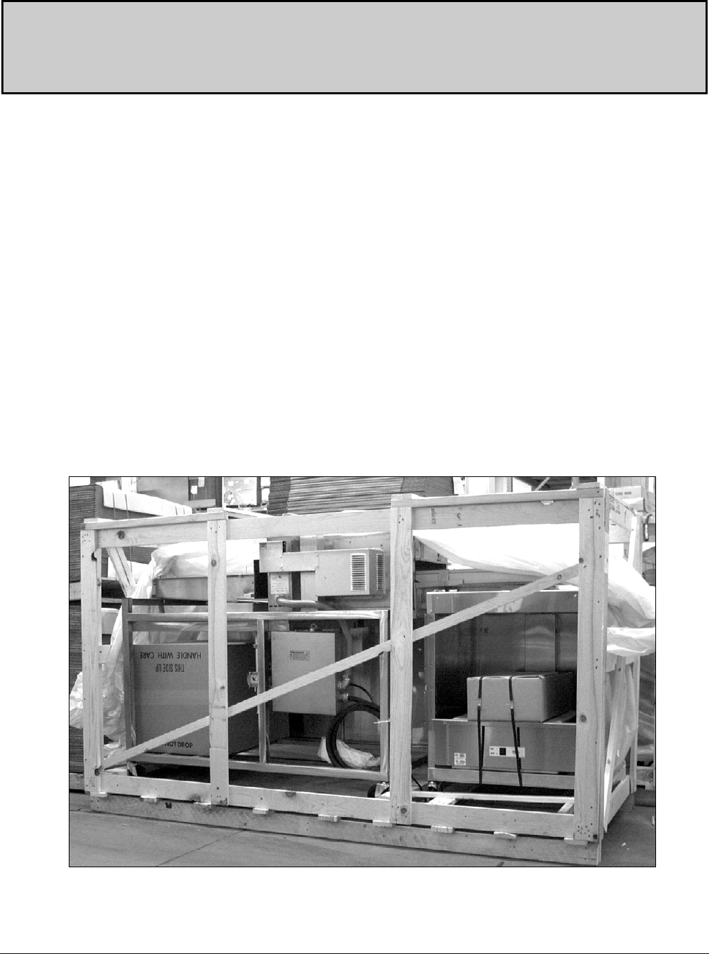
Figure 1-1 shows the system in the crate ready to
be unpacked. The cartons under the Thermoglaze
contain the glaze trough and oven guard. See
Section 4 to assemble the unit. The carton in the
Thermolizer contains the doors and other interior
parts. See Thermolizer manual for assembly
instructions.
The Thermoglaze system has been designed for
quick assembly and installation. Within a few
minutes of receiving the system, the installer can
have the Thermoglaze ready to make donuts if
the electrical connections are properly installed
and inspected by the prevailing local authorities.
Figure 1-1

Belshaw Bros., Inc. • 1750 22nd Ave. S. • Seattle, WA 98144 • Phone 206-322-5474 • Fax 206-322-5425
2 MN-1716EN Thermoglaze 50
Identification 2
This information is key to identification for
service or ordering parts on the ThermoGlaze.
When servicing the equipment, please have the
Model and serial number so the technician can
order the correct parts for you. To identify which
Thermoglaze system you have, please use the
following model number key:
THERMOGLAZE DESCRIPTION KEY
Model No: - Doz/hr: - Glaze Pump: Opt. Items: - Voltage: - Freq: - Phase: -
TG 50 G = Gear Pump V = End Cover -50 208 50 1
25 L = Lift Pump M = Mono -50 220/240 60 3
N = No Pump A = RF Oper. 400/230 3 w/N
B = LB Oper. 415/240
Location: C = LF Oper.
D = RB Oper.
C = CE/Export T = LB Oper/SPL w/
D = Domestic/Nema (thermolizer cabinet)
B = Export/Non-CE
W = Domestic/Pin/Sleeve
E = Aust/NZ
Note: TG-50 is RF/LB Operate only, without Thermolizer - Screen 17” x 25”
TG-25 includes built in Thermolizer for 12 ½” x 17” Screen
Part No. Description Key Drawings
22080 OBS USE 22113, TG-25 JR. TJ-2004, TJ-4000 w/120V
22081 OBS USE 22114, TG-25 JR. TJ-2006, TJ-4000 w/120V
22082 OBS USE 22115, TG-25 JR. TJ-2005, TJ-4000 w/120V
22083 OBS USE 22116, TG-25 JR. TJ-2007, TJ-4000 w/120V
22113 TG-25-GA-208-60-1-D JR. TJ-2004, TJ-4002
22114 TG-25-GB-208-60-1-D JR. TJ-2006, TJ-4002
22115 TG-25-GC-208-60-1-D JR. TJ-2005, TJ-4002
22116 TG-25-GD-208-60-1-D JR. TJ-2007, TJ-4002
22117 TG-25-GA-220/240-60-1-D JR. TJ-2004, TJ-4002
22118 TG-25-GB-220/240-60-1-D JR. TJ-2006, TJ-4002
22119 TG-25-GC-220/240-60-1-D JR. TJ-2005, TJ-4002

Belshaw Bros., Inc. • 1750 22nd Ave. S. • Seattle, WA 98144 • Phone 206-322-5474 • Fax 206-322-5425
Thermoglaze 50 MN-1716EN 3
Part No. Description Key Drawings
22120 TG-25-GD-220/240-60-1-D JR. TJ-2007, TJ-4002
22231 TG-25-GB-415-50-3w/N-C JR TJ-2006, TJ-4004 (415/240V)
22247 TG-25-GB-415-50-3w/N-E RVO TJ-2012, TJ-4005 (415/240V)
22010 TG-50-G-208-60-1-W STD TNG-2011, TNG-4008
22054 TG-50-GV-208-60-1-D STD TNG-2011, TNG-4008
22011 TG-50-GV-220/240-60-1-D STD TNG-2011, TNG-4008
22013 TG-50-GV-400/230-50-3-C STD TNG-2011, TNG-4012
22067 TG-50-GM-400/230-50-3-C SPL TNG-2012, TNG-4012
22251 TG-25-GT-208-60-1-D SPL TJ-2013, TJ-4002
Optional Line Items:
SL200-0004 Glazing Screen - 17” x 25” – TG-50
TJ-0001 Glazing Screen – 12 ½” x 17” – TG-25
TJ-1012 Front Shield Kit – TG-25
SK-1257 Spare Parts Kit – TG-50 (included)
SK-1258 Service Kit – TG-50 (208-220/240V-60H-1P-DOM)
SK-1280 Spare Parts Kit – TG-25 (included)
SK-1281 Service Kit – TG-25 (208-220/240V-60H-1P-DOM)
SK-1281CE Service Kit – TG-25 (415/240V-50H-3P-CE)
SK-1314 Service Kit – TG-50 (400/230V-50H-3P-CE)
TNGG-1011 Heater Assembly - Glaze Tank TG-50
TZ-6 & TZ-17 Thermolizer (order service kits separate)
TNGG-0079 Cover; Glaze Tank – TG-50 (included except 22010)
TNGV-2004 Oven Mod. Kit & Lincoln Oven Parts (208V-60H-1P-DOM)
TNGV-2005 Oven Mod. Kit & Lincoln Oven Parts (240V-60H-1P-DOM)
TNGV-2009 Oven Mod. Kit & Lincoln Oven Parts (400/230V-50H-3P-CE)
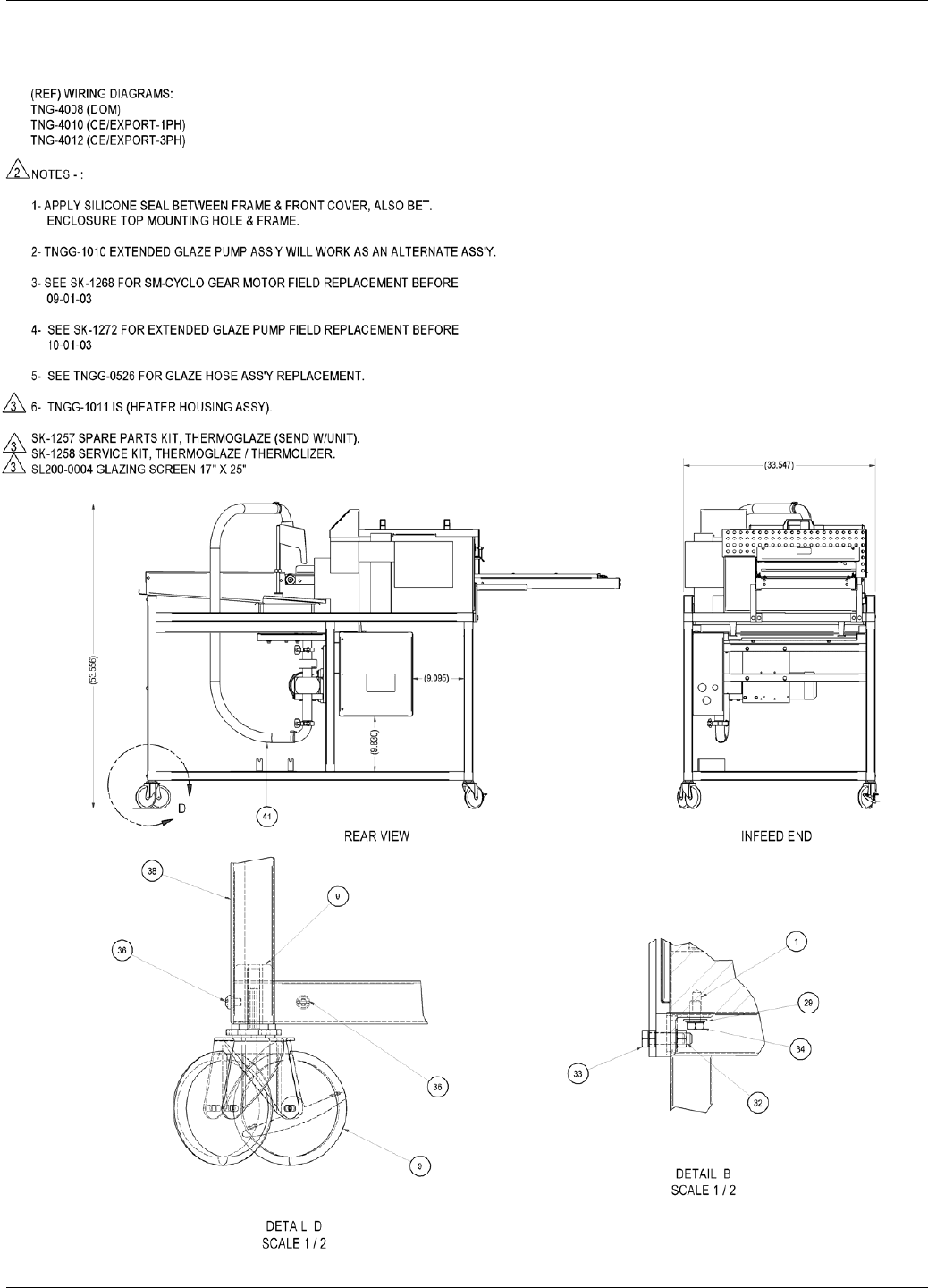
08/19/05

Belshaw Bros., Inc. • 1750 22nd Ave. S. • Seattle, WA 98144 • Phone 206-322-5474 • Fax 206-322-5425
4 MN-1716EN Thermoglaze 50
Installation 3
WARNING
To avoid electrocuting yourself or damaging
the Thermoglaze, never allow water, steam,
cleaning solution, or other liquid to enter the
electrical panels or connections
Electrical:
Model Dimensions Power Requirements
TG21586 88"L x 40W x
63"H See data tag
Make sure that the power requirements of the
Thermoglaze, shown on the data plate, match
your power source.
Only plug in to power source that matches the
required voltage and current for the
Thermoglaze. (The Thermoglaze unit TG50
comes standard with a Hubbel 360P6W plug that
needs a 360C6W socket or equivalent for
electrical current.
Thermoglaze must be electrically grounded and
connected in compliance with the National
Electrical Code, ANSI-NFPA 70, and applicable
municipal building codes.
Do not apply electrical power to the system until
the assembly has been completed. See Section 4
for the assembly of the Thermoglaze.
Venting:
Local codes prevail. The authorities having
jurisdiction are stated in NFPA 96-1994
regarding requirements for the Thermoglaze.
Building Layouts:
Specification sheets and AutoCAD drawings for
use in developing architectural drawings can be
provided by request. Please call your Belshaw
Bros., Inc. representative for help in defining
your requirements.
Belshaw Bros., Inc. • 1750 22nd Ave. S. • Seattle, WA 98144 • Phone 206-322-5474 • Fax 206-322-5425
Thermoglaze 50 MN-1716EN 5
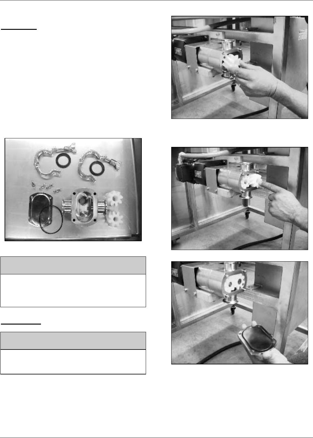
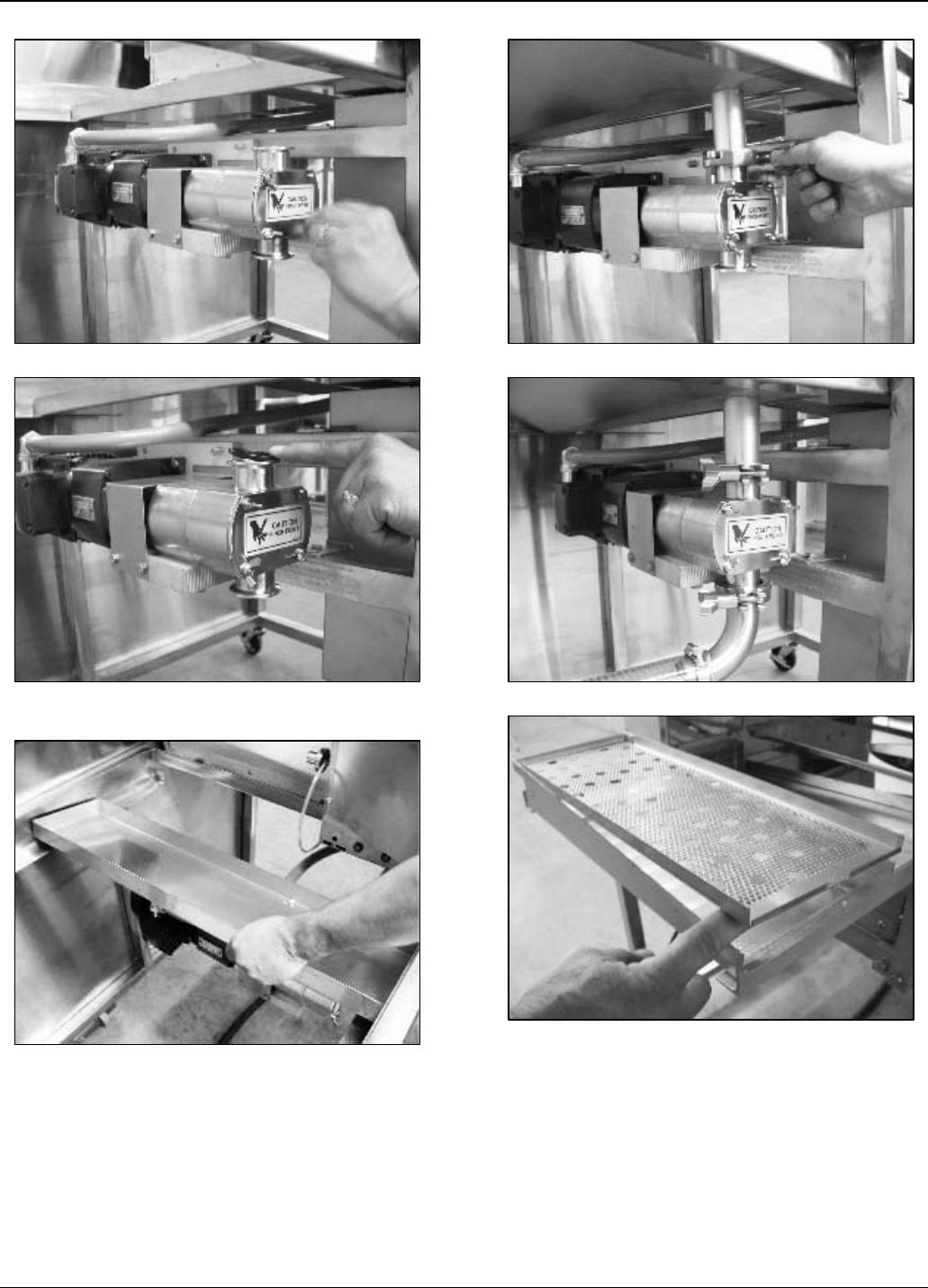
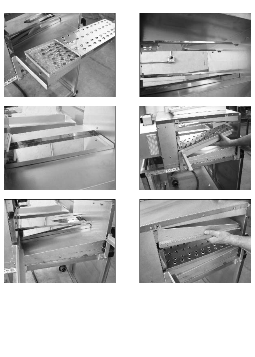
Assembly 4
Clean all parts with mild soap and water and
let dry before assembly and applying
electrical power to the equipment.
The Thermoglaze unit is design for ease of
assembly and use. The system is crated in a
manner so there are few pieces to put together
once the Thermoglaze is in place for production.
After unpacking the system per the uncrating
instructions, 2 items need to be placed on the
Thermoglaze to finish assembly, the glaze trough
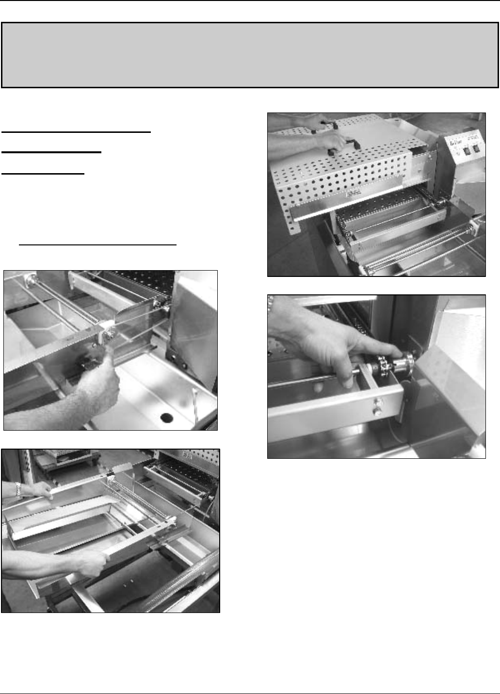
and the heat shield. First, the Glaze trough slips
into the 2 holes on either side of the drain tray
with the waterfall headed toward the oven. See
figure 4-1 and 4-4 for help setting the trough in
place. After the trough is in place attach the glaze
hose to the trough by pushing it in the hose
mount in the center of the trough. Second is the
Heat Shield over the oven portion of the
Thermoglaze. Slip it over the oven using the
handles provided until the guard locks over the
back of the oven. See figure 4-1 for a photo of
the location of the heat shield.
To help familiarize you with your Thermoglaze,
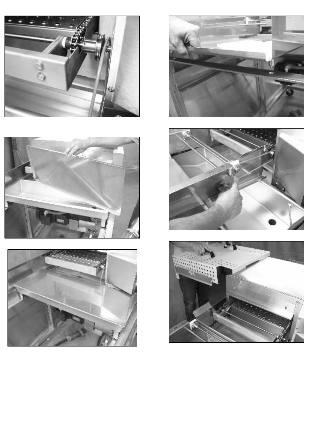
please study the following photographs:
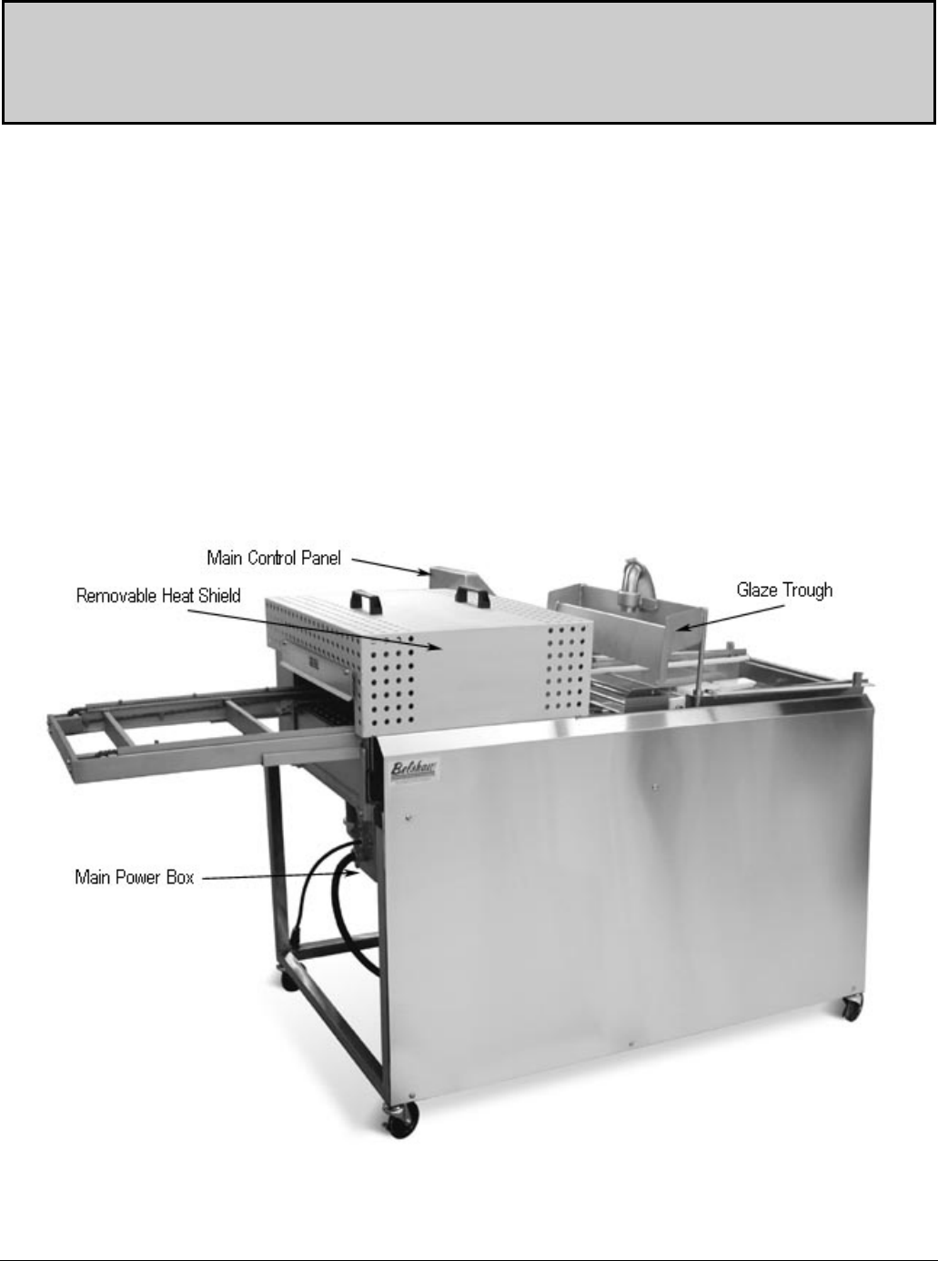
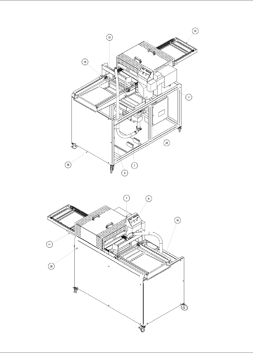
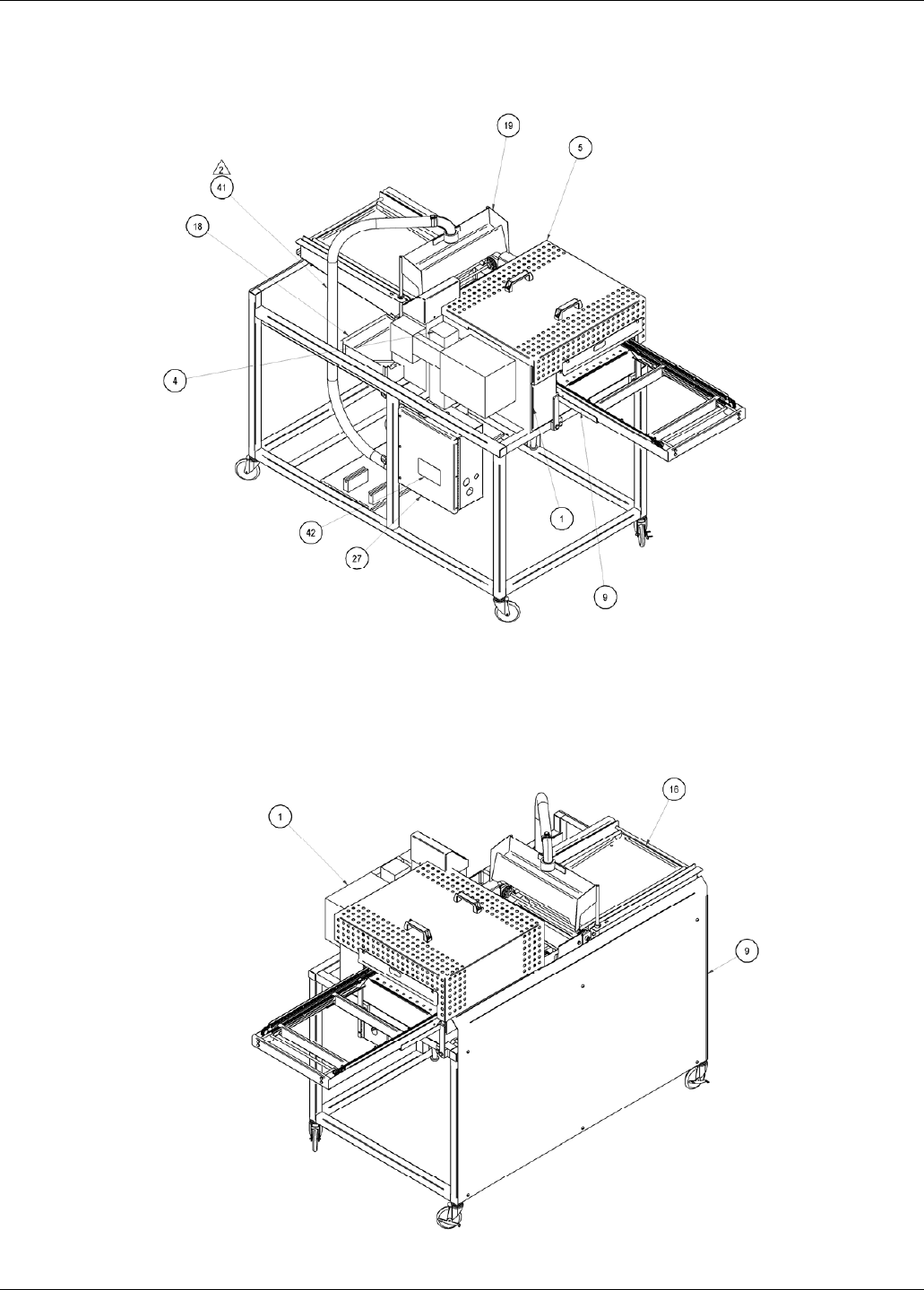
Figure 4-1 Front view:
Belshaw Bros., Inc. • 1750 22nd Ave. S. • Seattle, WA 98144 • Phone 206-322-5474 • Fax 206-322-5425
6 MN-1716EN Thermoglaze 50
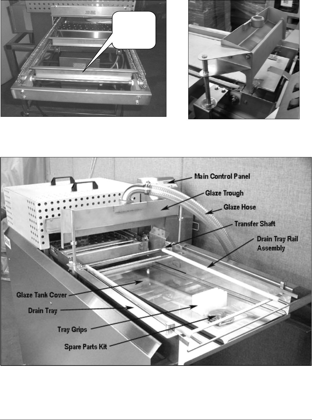
Figure 4-2 Infeed – Left hand view. Figure 4-3 Swing away glaze trough.
(Optional)
Figure 4-4 Right Hand View:
Transfer
Conveyor
Assembly
Belshaw Bros., Inc. • 1750 22nd Ave. S. • Seattle, WA 98144 • Phone 206-322-5474 • Fax 206-322-5425
Thermoglaze 50 MN-1716EN 7
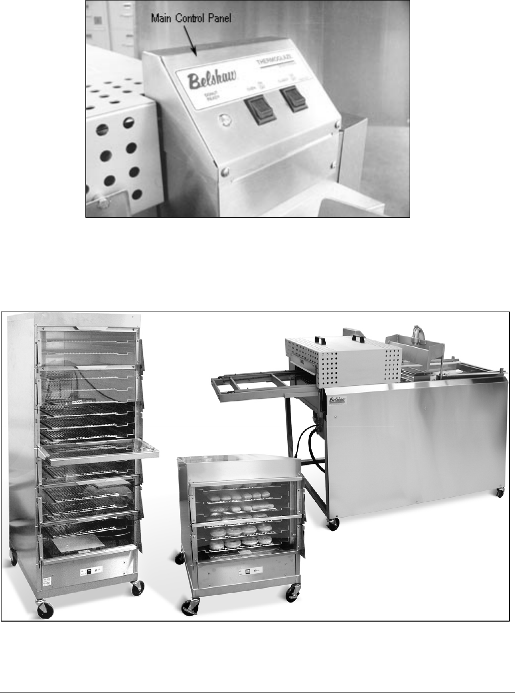
Figure 4-5 Control Panel View:
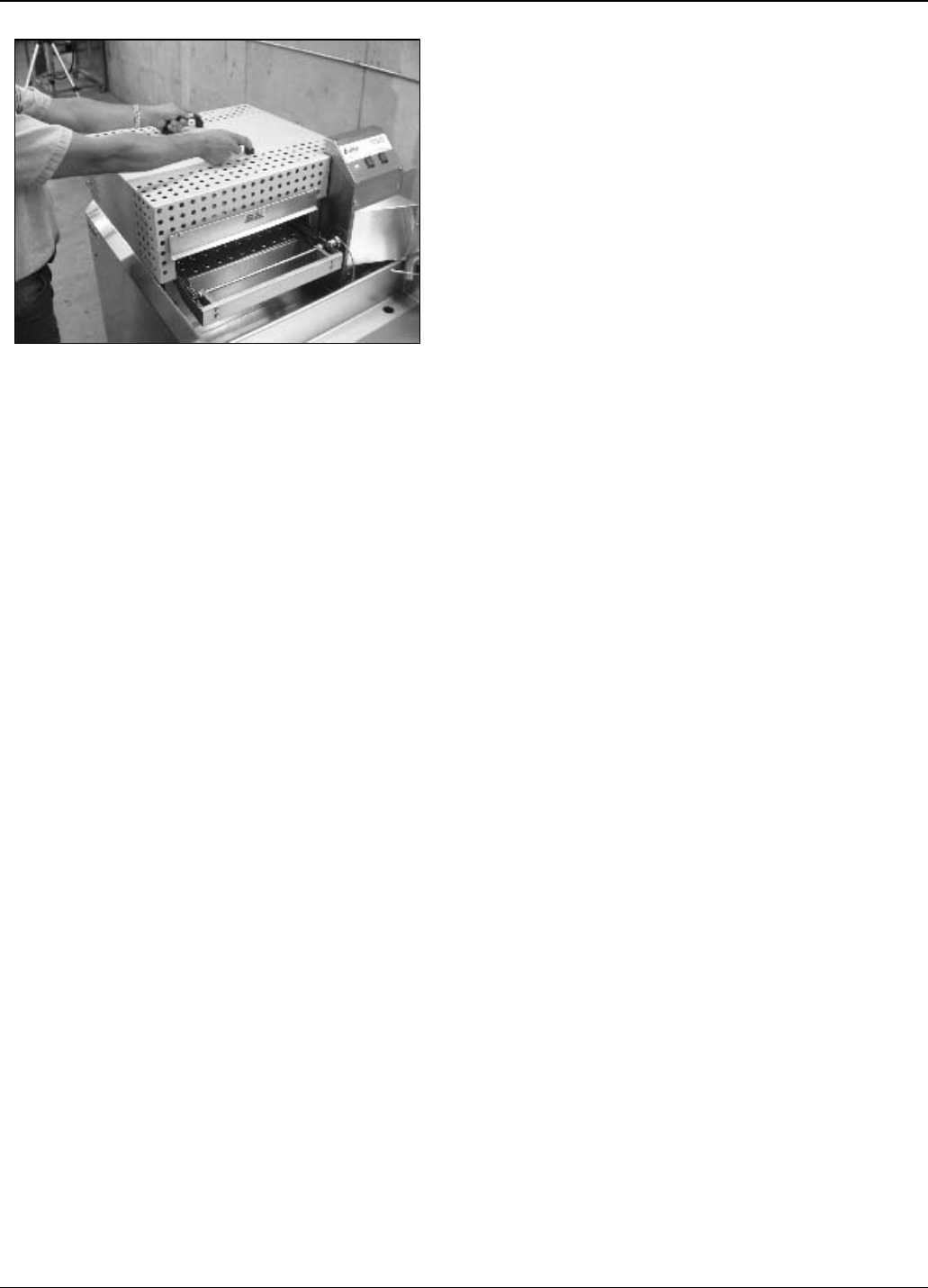
The Thermoglaze system consists of a Thermoglaze
unit and the Thermolizer. They are placed in unison
in the area located for the production of donuts. See
Figure 4-6 for Thermoglaze system.
Figure 4-6 Thermoglaze System.
Belshaw Bros., Inc. • 1750 22nd Ave. S. • Seattle, WA 98144 • Phone 206-322-5474 • Fax 206-322-5425
8 MN-1716EN Thermoglaze 50
Operation 5
• Turn on main power switch and allow to heat
to operating temperature. (Note: conveyor
will not move until the oven is up to
operating temperature and the donut
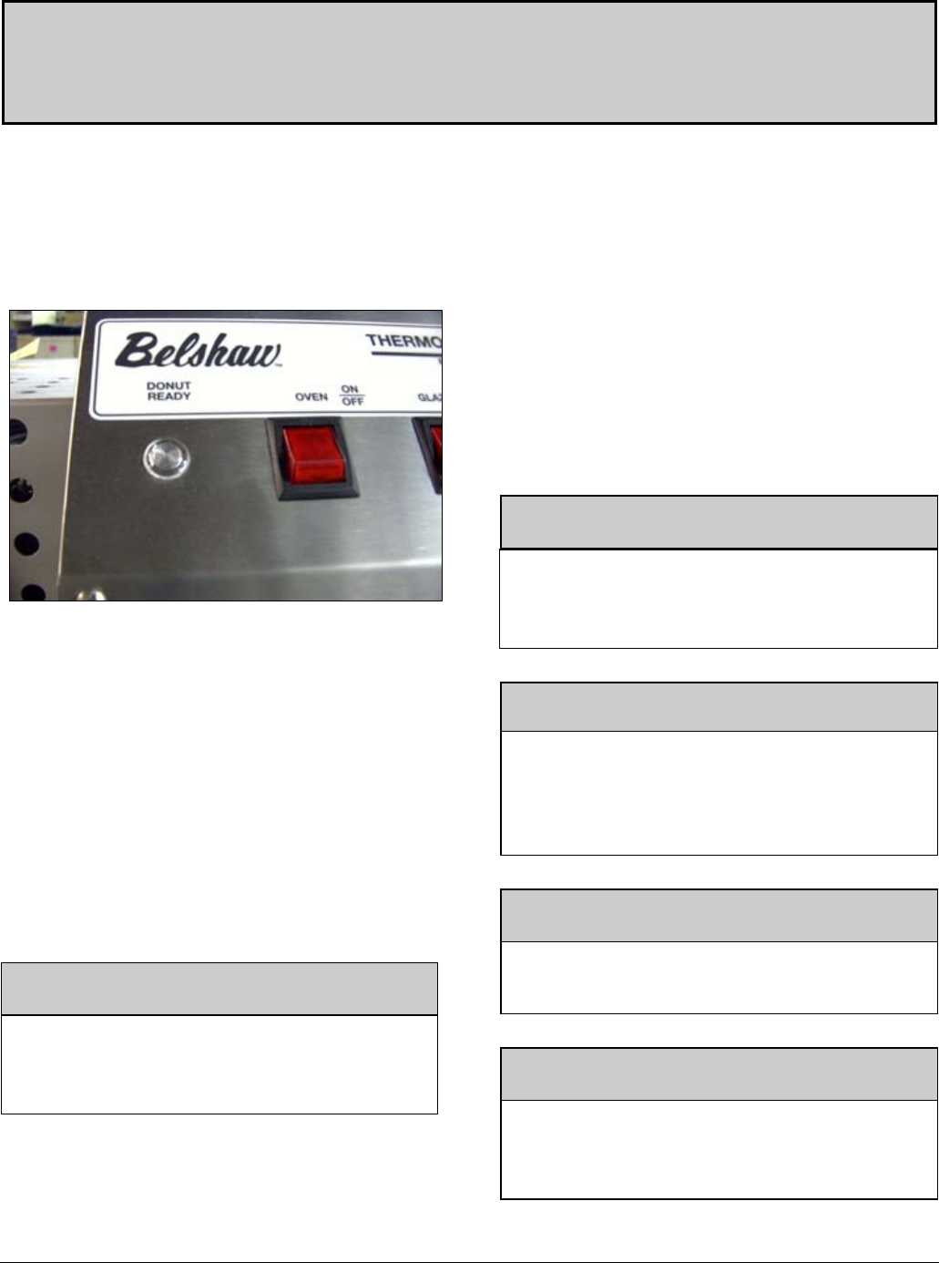
ready light is on. See Figure 5-1.)
Figure 5-1. Oven Ready Light.
• Turn on the Thermolizer and heat for 30
minutes to allow it to reach operating
temperature. See Thermolizer manual for
more operating instructions.
• Load glaze reservoir with 40 pounds (one
large bucket) of glaze and turn on the glaze
pump.
• To swing the glaze trough back, turn off
glaze pump, lift up on the mount slightly and
rotate to the trough to the rear. (Optional
Equipment) See Figure 4-3.
WARNING
Do not operate glazer without glaze or water
in the pump. Doing so may cause permanent
damage to the pump.
• After the donuts have been in the
Thermolizer for at least 20 minutes (60
minutes for filled product), turn on glazer
using the on switch located on the main
control panel.
• After the donuts are thawed, place a screen of
donuts from Thermolizer box to the infeed
end of the Thermoglaze conveyor and allow
the screen to travel through the oven and
glazer. This takes approximately 3 minutes.
• When the screen of donuts is through the
glazer and stopped forward travel, place the
glazed product on a rack for cooling using
the 2 delrin tray grips provided with the unit.
WARNING
To avoid burning yourself, never touch the
Thermoglaze unit, conveyor, or interior of the
oven while the machine is in use.
WARNING
Thoroughly clean and dry the floor if water or
other materials are spilled. Materials spilled
on the floor may cause serious injury and loss
of life.
WARNING
Conveyor will automatically start when
Thermoglaze reaches operating temperature.
CAUTION!
Donut screens are hot after coming out of the
glazer and will burn you if you grab them
without the handles.
Belshaw Bros., Inc. • 1750 22nd Ave. S. • Seattle, WA 98144 • Phone 206-322-5474 • Fax 206-322-5425
Thermoglaze MN-544EN 9
Cleaning 6
Daily TG Cleaning
Instructions
Disassembly
1. Allow the Thermoglaze to completely
cool. (All material must under 130º)
2. Pump the unused glaze back into a bucket.
3. Disconnect the TG from power!
4. Remove the glaze trough.
5. Remove the drive belt.
6. Remove the glazer drain tray.
7. Remove the oven heat shield.
8. Disconnect the conveyor drive coupling.
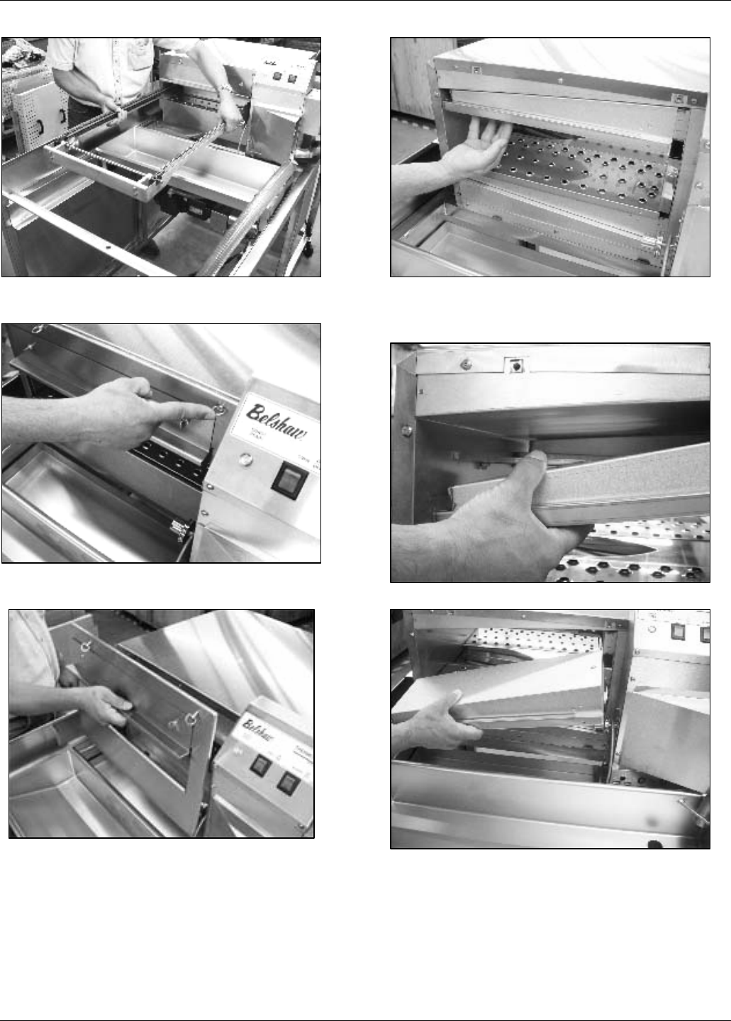
Belshaw Bros., Inc. • 1750 22nd Ave. S. • Seattle, WA 98144 • Phone 206-322-5474 • Fax 206-322-5425
10 MN-1716EN Thermoglaze 50
9. Remove the conveyor assembly through
the outfeed end of the oven.
10. Turn the end cover latches
counterclockwise.
11. Remove the end covers.
12. Lift up on the outfeed upper finger housing and
slide it to the rear of the oven disengaging it
from the mounting bracket.
13. Lower the end of the finger assembly.
14. Pull the finger assembly off the duct on the back
of the oven and remove it.
Belshaw Bros., Inc. • 1750 22nd Ave. S. • Seattle, WA 98144 • Phone 206-322-5474 • Fax 206-322-5425
Thermoglaze 50 MN-1716EN 11
15. Lift up on the outfeed lower finger
assembly and remove it.
16. Lift up on the infeed upper finger
assembly.
17. Slide the infeed upper finger assembly to
the rear of the oven.
18. Remove the infeed upper finger assembly.
19. Remove the infeed finger assembly.
20. Lift up on the outside end of the upper air duct
panel.
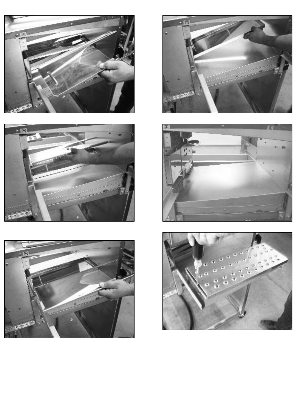
Belshaw Bros., Inc. • 1750 22nd Ave. S. • Seattle, WA 98144 • Phone 206-322-5474 • Fax 206-322-5425
12 MN-1716EN Thermoglaze 50
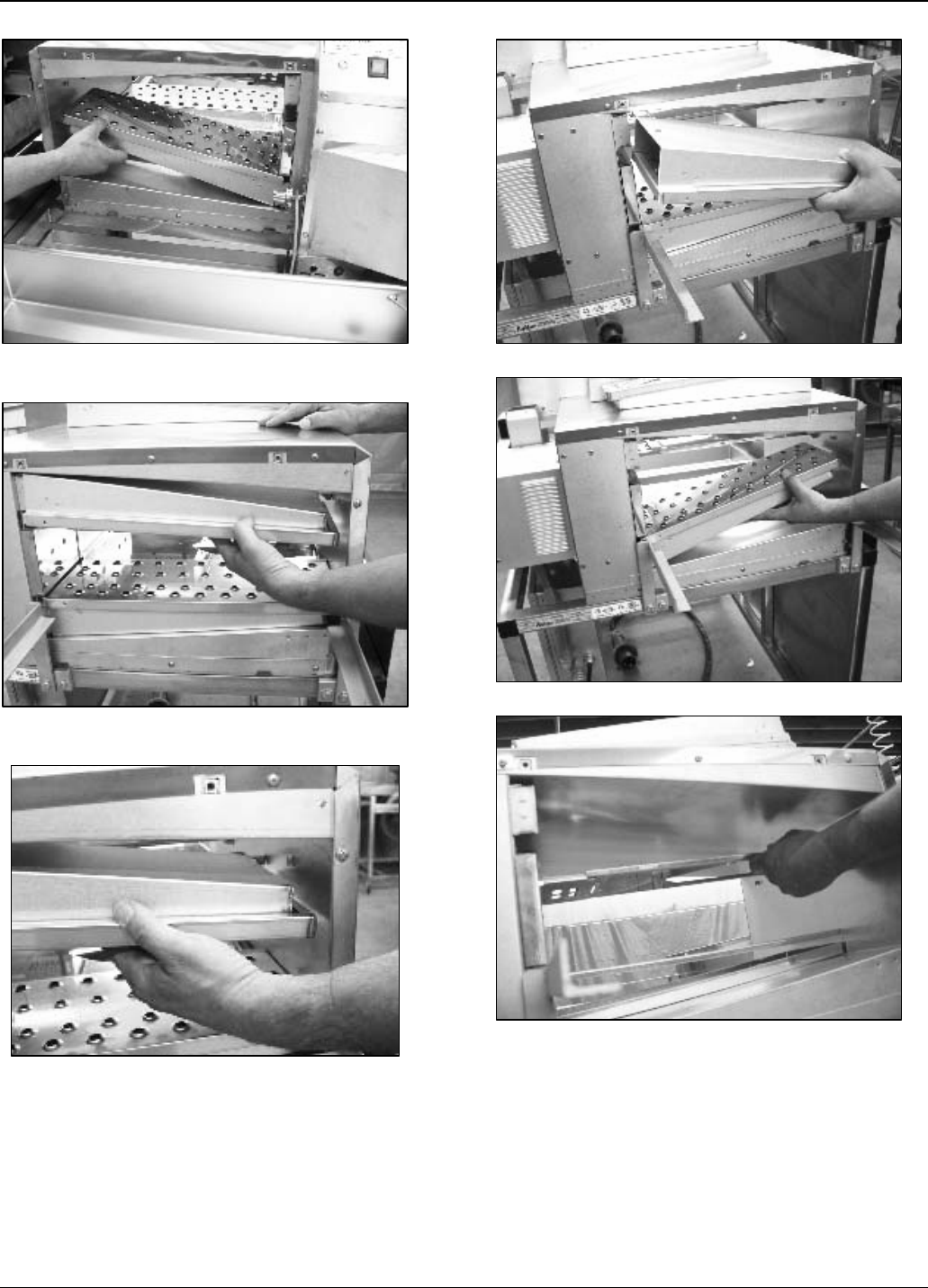
21. Remove the upper air duct panel
22. Lift up on the outside end of the lower air
duct panel.
23. Remove the lower air duct panel.
24. Remove the oven crumb tray
25. Oven with all parts removed.
26. Insert flat tip screwdriver into finger
assembly if it cannot be removed by hand.
Belshaw Bros., Inc. • 1750 22nd Ave. S. • Seattle, WA 98144 • Phone 206-322-5474 • Fax 206-322-5425
Thermoglaze 50 MN-1716EN 13
27. Remove the finger cover.
28. Remove the columnating plate.
29. Loosen the lower glaze hose clamp.
30. Remove the lower glaze hose clamp and
gasket.
31. Remove the upper pump clamp.
32. Lift the glaze reservoir and remove the gasket
Belshaw Bros., Inc. • 1750 22nd Ave. S. • Seattle, WA 98144 • Phone 206-322-5474 • Fax 206-322-5425
14 MN-1716EN Thermoglaze 50
33. Remove the glaze reservoir and hose.
34. Remove the drip pan.
35. Remove unscrew the 4 glaze pump cover
wing nuts.
36. Remove the glaze pump cover and “O” ring.
37. Remove the glaze pump body.
38. Insert a flat tip screw driver into the slot to
loosen the pump body if it can not be
removed by hand.
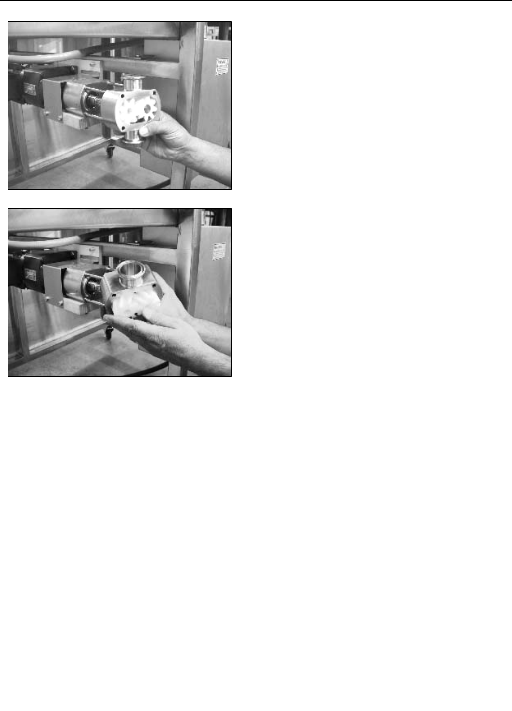
Belshaw Bros., Inc. • 1750 22nd Ave. S. • Seattle, WA 98144 • Phone 206-322-5474 • Fax 206-322-5425
Thermoglaze 50 MN-1716EN 15
39. Remove the pump body and impellers.
40. Remove the impellers from the pump body.
Belshaw Bros., Inc. • 1750 22nd Ave. S. • Seattle, WA 98144 • Phone 206-322-5474 • Fax 206-322-5425
16 MN-1716EN Thermoglaze 50
Cleaning
1. Hand wash all parts of the oven and
glazer with warm soapy water.
2. Do not use caustic cleaners on oven parts.
3. You may use an approved oven cleaner
on the stainless steel finger cover only.
(see step 27 of Disassembly)
4. Do not use oven cleaner on any other part
of the oven or glazer!
5. Do not hose/spray down any part of this
machine.
6. Glaze pump body and parts.
CAUTION
Failure to properly clean or lubricate glaze
pump may cause damage to the pump gear
impellors.
Assembly
NOTE
Lubricate the pump body, shaft “o” ring and
gear impellors with food grade mineral oil.
1. Install the glaze pump body.
2. Install the drive gear impeller. Line up
the flat on the shaft with the flat in the
impeller.
3. Install the lay gear impeller.
4. Install the “O” ring into the glaze pump
cover. Make sure it stays in place and you
do not pinch it between the pump and
cover. The “O” ring may need to be
stretched before installing.
Belshaw Bros., Inc. • 1750 22nd Ave. S. • Seattle, WA 98144 • Phone 206-322-5474 • Fax 206-322-5425
Thermoglaze 50 MN-1716EN 17
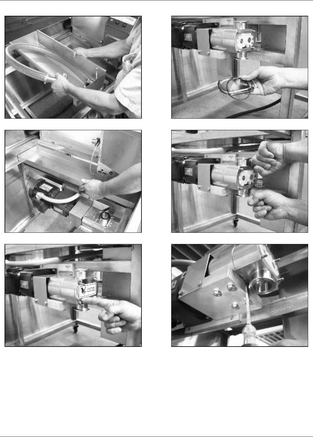
5. Install the 4 wing nuts finger tight.
6. Set the upper gasket on top of the glaze
pump.
7. Install the drip pan and glaze reservoir.
8. Install the upper clamp.
9. Install the lower gasket, hose and clamp.
10. Install the columnating plates.
Belshaw Bros., Inc. • 1750 22nd Ave. S. • Seattle, WA 98144 • Phone 206-322-5474 • Fax 206-322-5425
18 MN-1716EN Thermoglaze 50
11. Install the finger covers.
12. Install the oven crumb tray.
13. Install the lower air duct panel.
14. Install the upper air panel assembly.
15. Install the lower infeed finger assembly.
16. Install the upper infeed finger assembly
by slipping it over the duct on the back of
the oven.
Belshaw Bros., Inc. • 1750 22nd Ave. S. • Seattle, WA 98144 • Phone 206-322-5474 • Fax 206-322-5425
Thermoglaze 50 MN-1716EN 19
17. Then lift it up, slide it to the front of the
oven and hook it on the brackets.
18. Install the lower outfeed finger assembly.
19. Install the upper outfeed finger assembly.
20. Install the infeed end cover by lining up
the slots at the bottom of the end cover
with the brackets on the oven and push in
on the latches and turn clock wise.
21. Install the outfeed end cover same as the
infeed.
22. Insert the conveyor through the outfeed
end of the oven.
Belshaw Bros., Inc. • 1750 22nd Ave. S. • Seattle, WA 98144 • Phone 206-322-5474 • Fax 206-322-5425
20 MN-1716EN Thermoglaze 50
23. Pull the drive coupling back and line it up
with the conveyor drive shaft.
24. Install the glaze reservoir cover
25. Glaze reservoir installed.
26. Install the glaze drain tray.
27. Connect the drive belt.
28. Set the heat shield on top of the oven.
Belshaw Bros., Inc. • 1750 22nd Ave. S. • Seattle, WA 98144 • Phone 206-322-5474 • Fax 206-322-5425
Thermoglaze 50 MN-1716EN 21
29. Slide the heat shield over the oven.

Belshaw Bros., Inc. • 1750 22nd Ave. S. • Seattle, WA 98144 • Phone 206-322-5474 • Fax 206-322-5425
22 MN-1716EN Thermoglaze 50
Maintenance 7
The ThermoGlaze is engineered to need little
maintenance. By keeping the system clean, the
equipment will last for years. The only
maintenance that is required is the following:
When cleaning the donut system, check all
rubber gaskets for wear and replace when
necessary. Check for wear on impellers of the
glaze pump, replace when necessary. .
DO NOT spray machine with water or cleaning
agents to clean. Only wipe main unit off with
damp cloth.

Belshaw Bros., Inc. • 1750 22nd Ave. S. • Seattle, WA 98144 • Phone 206-322-5474 • Fax 206-322-5425
Thermoglaze 50 MN-1716EN 23
Troubleshooting 8
Call Belshaw Bros. at (206)322-5474, or (800)
578-2547. One of our customer support
representatives will be happy to help you. When
you call, please specify the following:
• The model name of the machine.
• The serial number of the machine.
• The voltage, phase, and hertz (cycle) of
the machine. This information can be
found on the small, rectangular data
tag/plate.
CAUTION
If you perform repairs yourself or have them
performed by anyone other than Belshaw
Bros. or a service technician authorized by
Belshaw Bros., you do so at your own risk.
Following is a troubleshooting chart to help you
identify and solve some basic problems.
WARNING
Disconnect the machine from the power
source before disassembling, repairing, or
wiring.
NOTE
See page 31 of the Maintenance Appendix for
oven troubleshooting.

Belshaw Bros., Inc. • 1750 22nd Ave. S. • Seattle, WA 98144 • Phone 206-322-5474 • Fax 206-322-5425
24 MN-1716EN Thermoglaze 50
CONVEYOR WILL NOT MOVE
Possible Causes What To Do
Oven not to correct temperature yet. Wait until the oven comes to temp.and the ready
light comes on.
Conveyor is jammed. Check for obstruction in conveyor and remove.
Motor circuit breaker is tripped. Push the black circuit breaker reset at bottom of
oven control panel.
GLAZER WILL NOT PUMP GLAZE
Glazer motor is not running. Check to make sure the motor is running.
(See Pump Motor Will Not Run)
Glazer pump impellers are worn. 1. Disconnect power.
2. Replace impellors.
GLAZE IS MISSING THE DONUTS ON ONE SIDE OF THE GLAZE SCREEN
Glazer or glaze trough is not level. Adjust level of glaze trough by moving set collar.
Glaze pump is running too slow. 1. Disconnect from power.
2. Open Electrical Enclosure.
3. Turn glazer speed control clockwise.
4. Close Electrical Enclosure.

Belshaw Bros., Inc. • 1750 22nd Ave. S. • Seattle, WA 98144 • Phone 206-322-5474 • Fax 206-322-5425
Thermoglaze 50 MN-1716EN 25
THE PUMP MOTOR WILL NOT RUN
Possible Causes What To Do
The connection of the power cord to the power
source is faulty. Make sure the power cord is fully plugged in to a
proper power source.
The circuit breaker has been tripped. 1. Disconnect from power.
2. Open electrical enclosure.
3. Reset circuit breaker.
4. Close electrical enclosure.
THE FILL HOSE IS LEAKING
Possible Causes What To Do
Fill hose is leaking at the connection. Hose bracket needs adjusting or tightening.
Fill hose is leaking near the pump. Check for missing or damaged o-ring.
Belshaw Bros., Inc. • 1750 22nd Ave. S. • Seattle, WA 98144 • Phone 206-322-5474 • Fax 206-322-5425
26 MN-1716EN Thermoglaze 50
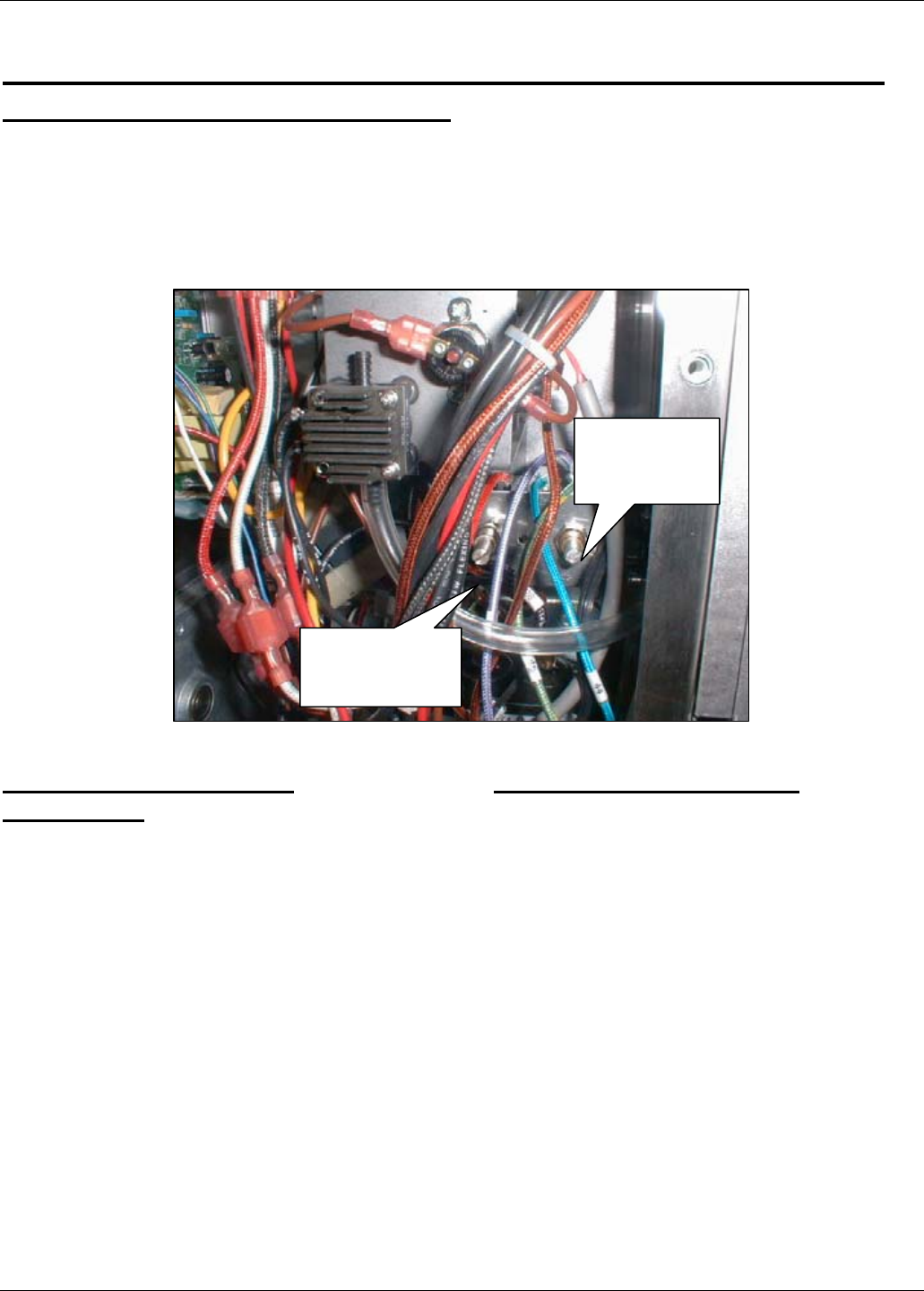
Calibration Procedure for Temperature and Cook Time on
the Thermoglaze Model TG50
Turn off power to the TG50 before removing any
access covers. This procedure should be
performed only by qualified service technicians.
Remove the electrical box cover on the oven to
access the temperature and speed control
adjustment potentiometers. The following is a
photo of the location of the adjustment
potentiometers for the temperature and cooking
time for the Belshaw TG50 Thermoglaze.
Speed control/cook time
adjustment:
Turn on the oven and allow it to heat for 30
minutes.
Put a glaze screen on the conveyor chains that
run through the oven. With the oven in operation,
time the leading edge of the screen as it enters
the oven until the leading edge just leaves the
exit end of the oven. Adjust the potentiometer
until the desired time/speed is found. To increase
the cook time, turn the potentiometer clockwise.
To decrease the cook time, turn the
potentiometer counterclockwise. The factory
setting for cook time for the TG50 is 1 ½
minutes.
Temperature Adjustment:
Measure the temperature from the lower baffle
on the exit end of the oven. Place a thermocouple
in the hole located on the baffle, 3rd row from the
outside, 3rd hole from the back side of the oven.
Note: The back side of the oven has a fan motor
extended from it. Adjust the temperature by
rotating the potentiometer located to the right of
the speed control, clockwise increases the
temperature, and counterclockwise decreases the
temperature. The factory setting is 400º F.
Temperature
Adjustment
Speed Control
Adjustment

Belshaw Bros., Inc. • 1750 22nd Ave. S. • Seattle, WA 98144 • Phone 206-322-5474 • Fax 206-322-5425
Thermoglaze 50 MN-1716EN 27
Appendix 9
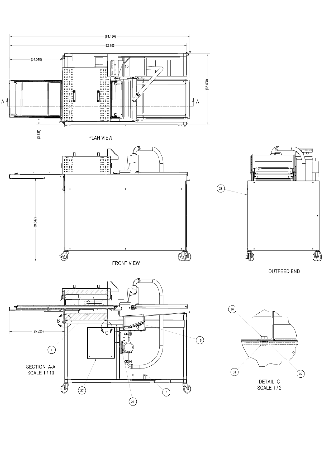
Final Assembly Drawing TNG-2011
Parts Diagrams TNGG-1008
TNGG-0526
TNGG-1009
TNGV-2004
Wiring Diagram TNG-4008
Maintenance Appendix for ThermoGlaze Oven
Service Kit Parts List
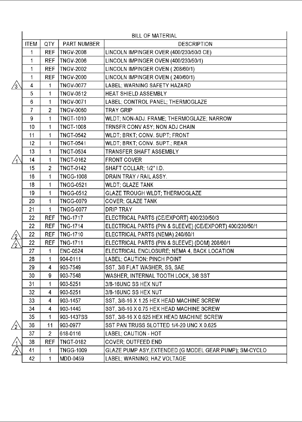
Belshaw Bros., Inc. • 1750 22nd Ave. S. • Seattle, WA 98144 • Phone 206-322-5474 • Fax 206-322-5425
28 MN-1716EN Thermoglaze 50
TNG-2011. THERMOGLAZE ASSEMBLY
Belshaw Bros., Inc. • 1750 22nd Ave. S. • Seattle, WA 98144 • Phone 206-322-5474 • Fax 206-322-5425
Thermoglaze 50 MN-1716EN 29
TNG-2011. THERMOGLAZE ASSEMBLY
Belshaw Bros., Inc. • 1750 22nd Ave. S. • Seattle, WA 98144 • Phone 206-322-5474 • Fax 206-322-5425
30 MN-1716EN Thermoglaze 50
TNG-2011. THERMOGLAZE ASSEMBLY
Belshaw Bros., Inc. • 1750 22nd Ave. S. • Seattle, WA 98144 • Phone 206-322-5474 • Fax 206-322-5425
Thermoglaze 50 MN-1716EN 31
TNG-2011. THERMOGLAZE ASSEMBLY
Belshaw Bros., Inc. • 1750 22nd Ave. S. • Seattle, WA 98144 • Phone 206-322-5474 • Fax 206-322-5425
32 MN-1716EN Thermoglaze 50
TNG-2011. THERMOGLAZE ASSEMBLY
Belshaw Bros., Inc. • 1750 22nd Ave. S. • Seattle, WA 98144 • Phone 206-322-5474 • Fax 206-322-5425
Thermoglaze 50 MN-1716EN 33
Belshaw Bros., Inc. • 1750 22nd Ave. S. • Seattle, WA 98144 • Phone 206-322-5474 • Fax 206-322-5425
34 MN-1716EN Thermoglaze 50
Belshaw Bros., Inc. • 1750 22nd Ave. S. • Seattle, WA 98144 • Phone 206-322-5474 • Fax 206-322-5425
Thermoglaze 50 MN-1716EN 35
Belshaw Bros., Inc. • 1750 22nd Ave. S. • Seattle, WA 98144 • Phone 206-322-5474 • Fax 206-322-5425
36 MN-1716EN Thermoglaze 50
Belshaw Bros., Inc. • 1750 22nd Ave. S. • Seattle, WA 98144 • Phone 206-322-5474 • Fax 206-322-5425
Thermoglaze 50 MN-1716EN 37

Belshaw Bros., Inc. • 1750 22nd Ave. S. • Seattle, WA 98144 • Phone 206-322-5474 • Fax 206-322-5425
38 MN-1716EN Thermoglaze 50
SK-1258 R5
REC. QTY PART NUMBER DESCRIPTION
THERMOGLAZE
1 EA #RLY-0008 RELAY (240V)
1 EA #SWT-0022-240 ILLUMINATED ROCKER SWITCH
1 EA #TDR-0015 TIME DELAY RELAY
5 EA 905-0242-7/8 HD SPRING PIN, 1/8 DIA X 7/8" LG
5 FT 905-0408-58 1 1/2 ID SUCTION HOSE (SPIRILITE) 58"
LG.
2 EA GL100-0116 GLAZE TUBE CLAMP
4 EA GL100-0171 GASKET
1 EA HG18-0031-4 CASTER 4"
1 EA HG18-0031B-4 CASTER W/BRAKE 4"
1 EA TNGG-0034C DRIVE GEAR
1 EA TNGG-0034D LAY GEAR
4 EA TNGG-0034M WING NUTS, PUMP COVER
2 EA TNGG-0034T COVER O-RING
2 EA TNGG-0034Z PUMP O-RING, SHAFT
4 EA TNGT-0009 SPACER, DELRIN, WHITE
2 EA TNGT-0079 BEARING BLOCK, TRANSFER SHAFT
1 EA TNGT-0080 TRANSER SHAFT
2 EA TNGT-0082 TRANSFER SHAFT DRIVE BELT,-
ORANGE
2 EA TNGT-0167 REPL. CHAIN ASS'Y
2 EA TNGT-0169 IDLER SPROCKET, 38B10
1 EA TNGT-0171 CONVEYOR DRIVE SHAFT, OUTFEED
2 EA TNGV-0060 TRAY GRIP

November 1999 31 COUNTER TOP IMPINGER
TROUBLESHOOTING GUIDE
IMPINGER CTI
SYMPTOM POSSIBLE CAUSE EVALUATION
Incoming Power Supply Check breakers, reset if required Check power plug
to be sure it is firmly in the receptacle (if applicable).
Measure the incoming power, call Power Co., if
needed
Oven Fan Fuses, 5 Amp Check and/or replace
Fuse Holder Check and/or replace
High Limit Thermostat
Control Box (Note: High
Limit not used in ovens
S/N 3000352)
Check for voltage on both sides of the switch.
Terminals are normally closed. If open, reset and
test oven for proper operation. If thermostat and
below.) will not hold and control box temperature is
not exceeding 140°F (60°C), replace thermostat.
Fan Switch Check continuity between switch terminals. Check
and insure good wire connections
20 Minute Time Delay Check for supply voltage at terminal #1 to ground on
the 20-minute timer. If no voltage is present, trace
wiring back to power supply. If voltage is present at
terminal #1, check for supply voltage at terminal #2 to
ground. If no voltage is present, and the oven fan
switch is closed, replace the 20-minute timer.
Main Fan Relay Check continuity of coil. Check for power to relay
coil. Visually check for contact pull in and contact
condition. Check for voltage across relay terminals.
Fan Motor Check for opens, shorts, or grounds. WITH POWER
OFF: Turn fan blade to check for locked rotor.
Oven fan will not run
Capacitor Check for opens, shorts, or grounds. WARNING
Capacitor has a stored charge, discharge before
testing.
No main fan cool
down
20-Minute Timer Check for supply voltage at terminal #2 and #3 while
main fan is running. Turn off fan switch and supply
voltage should continue to be present for 20 min. at
terminal #2. Replace as needed.
Main fan continues to
run after cool down
20 Minute Timer NOTE: On/Off operation of fan switch will reset timer
to 20 minutes. If timer is accidentally reset, turn off
main breaker to cancel. If voltage continues to be
present at terminals 2 and 3 after 20 minutes, verify
fan switch contacts have opened, replace timer as
needed.
Fan Switch WITH POWER OFF: Close switch and check for
continuity across switch terminals.
20 Minute Timer See "Main Fan Motor will not run."
No control box
cooling
Cooling Fan Check for voltages at the fan motor, if present,
replace defective fan motor.

November 1999 32 COUNTER TOP IMPINGER
Main Oven Fan Check if main oven fan is working. If not, refer to
"Oven Fan Will Not Run".
Temperature Control
Board
Check for voltage input at the board. Turn the
temperature adjustment knob to the maximum
temperature position and check for voltage at the load
terminal. If present, and unit is not heating, refer to "Air
pressure switch" for next check. If no voltage is
present, proceed.
Thermocouple Sensor Check terminals, wiring, and proper location of the
sensor bulb. It must be in its spring holder located in
the inside, rear, lower right hand corner (viewed from
front) behind Finger #4. The thermocouple is a type J
and has one red lead (Neg.) and one white lead
(Pos.).WITH POWER ON AND THERMOCOUPLE
LEADS ATTACHED TO THE TEMPERATURE
CONTROL BOARD: Measure the D.C. millivolt output
of these leads. Refer to thermocouple chart in Section
D for proper readings. If these readings are not
achieved, replace the thermocouple.
Temperature Set
Potentiometer
Disconnect the potentiometer leads from the board.
Place ohm meter test leads on the blue and green pot.
leads. Reading should be 1 K ohms. Place meter leads
across the blue and purple pot. leads and rotate knob
from high to low. Repeat on green and purple leads.
Check for even rise and fall of ohms reading to insure
that there are no open or dead spots in the
potentiometer. Check each lead to ground for shorts.
Replace Pot. if it does not meet the above test.
Hi Limit Thermostat-
Oven Cavity
Terminals are normally closed, open at 660°F (350°C).
If open, push in reset button and retest. If thermostat
will not hold for maximum oven temperature, and oven
is not exceeding temperature dial setting, check for
proper location of capillary bulb in its spring holder. If
above checks okay, replace hi-limit thermostat.
Air Pressure Switch Check for voltage on both sides of the switch, if voltage
is present on one side only, check for air tube
blockage, adjust air switch, if above fails, replace
switch.
Heating Element Relay Check for voltage to the Relay coil and contacts. If
voltage is present and contactor will not activate,
replace the contactor. Check for voltage across relay
terminals.
Oven will not heat
Heater Element Check the amperage draw on each hot leg for proper
load. Check the rating plate for rating information. If
amp draw is low or high, check element for opens and
shorts.

November 1999 33 COUNTER TOP IMPINGER
Fan Switch Check continuity between switch terminals. Replace
as needed.
Conveyor Control
Transformer
Check for supply voltage at primary of transformer. If
no voltage is present, trace wiring back to fan switch.
Check for 24VAC at transformer secondary. If no
voltage is present, replace transformer.
Speed Adjustment
Potentiometer
This is a 5K ohm potentiometer. WITH POWER OFF:
Remove the leads from the motor control board at
terminals P1, P2, P3. With a digital meter, check the
ohm reading across the red and black leads. This
reading should be 5K ohms (± 10%) as the pot. is
rotated from low to high. Place meter leads on red
and white lead. Rotating the pot. slowly from low to
high, the meter reading should show an even
transition from 0 to 5K ohms (± 10%). There should
be no dead or open spots throughout the rotation of
the pot. Check all three (3) leads to ground. There
should be no continuity to ground. If any of the above
checks fail, replace the pot.
Conveyor Control Board Check for 24 VAC input to conveyor control. If no
voltage is present, trace wiring back to transformer. If
voltage is present at L1 and L2, check for D.C. output
at terminals A+ and A-. If there is AC voltage input,
but no D.C. voltage output, replace conveyor control
board.
Conveyor Gear Motor If there is D.C. voltage output from the conveyor
control, but the motor does not run, check the mini-
breaker (0.7 Amp). Check motor leads for opens,
shorts or continuity to ground. If motor fails above
test, replace motor.
Conveyor will not run
S/N 4000480 and Below
Conveyor Check conveyor drive coupling to be sure that it is
tight. Also check to see that coupling is engaged with
conveyor drive shaft. Check for any mechanical
misalignment or improper adjustment, also check for
worn bearings. A conveyor belt that is too tight will
cause excessive bearing wear and sometimes-
irregular speed.
Power Supply Check for steady supply voltage to oven. If voltage is
unsteady, contact power company.
Transformer Check for steady A.C. voltage output from transformer
and replace as needed.
Conveyor Control Check for steady D.C. voltage output from conveyor
control. If D.C. voltage output is unsteady, check
conveyor potentiometer (see "Speed Adjustment
Potentiometer" under Conveyor will not run). If the
potentiometer checks good, and the D.C. voltage is
unsteady, replace conveyor control.
Conveyor speed
varying or intermittent
D.C. Gearmotor Check motor brushes for excessive arching and/or
unusual wear. Replace brushes or gearmotor as
needed.

November 1999 34 COUNTER TOP IMPINGER
Fan Switch WITH POWER OFF: Check continuity between switch
terminals. Check and insure good wire connections.
Conveyor Control
Transformer
With the fan switch on, check for supply voltage at the
primary of the transformer. Check for voltage on the
secondary side of transformer (24 VAC) at J4 and J5 on
the conveyor control board. Replace as needed.
Speed Adjustment Pot This is a 50 K ohm potentiometer. WITH POWER OFF:
Remove the leads from the motor control board at
terminals P1, P2, P3. With a digital meter, check the
ohm reading across the red and black leads. This
reading should be 50K ohms (± 10%) as the pot. is
rotated from low to high. Place meter leads on red and
white lead. Rotating the pot. slowly from low to high, the
meter reading should show an even transition from 0 to
50 K ohms (±10%). There should be no dead or opens
spots throughout the rotation of the pot. Check all three
(3) leads to ground. There should be no continuity to
ground. If any of the above checks fail, replace the pot.
Conveyor Control
Board
Check for 24 VAC input to the control board at terminals
J4 and J5. If not present, check wiring back to control
transformer, if voltage is present at J4 and J5, check the
VDC output at terminals J2 (+) & J3 (-) (0-18 VDC). If
24 VAC is present at J4 and J5, but VDC is not present
at J2(+) & J3(-) replace board.
Conveyor Gear Motor If D.C. voltage is present at J2(+) and J3(-) and the
motor does not run, first check the mini breaker (.7Amp).
Check the leads to the motor for evidence of any shorts
or opens, and each lead to ground. If the motor fails the
above tests, replace motor.
Conveyor will not run
(S/N 3000481 & Above)
Conveyor Check for any mechanical misalignment or improper
adjustment, also check for worn bearings. A conveyor
belt that is too tight will cause excessive bearing wear
and sometimes, irregular speed.
Power Supply Check for steady supply voltage to oven. If voltage is
unsteady, contact Power Company.
Transformer Check for steady AC voltage output from transformer
and replace as needed.
Conveyor Control Check for steady D.C. voltage output from conveyor
control. If D.C. voltage output is unsteady, check
conveyor potentiometer (See Speed Adjustment
Potentiometer" under Conveyor will not run). If the
potentiometer checks good, and the D.C. voltage is
unsteady, replace conveyor control.
D.C. Gearmotor Check motor brushes for excessive arching and/or
unusual wear. Replace brushes or gearmotor as
needed
Magnet Check to insure that the magnet (cemented to shaft of
conveyor drive motor) has not been damaged, or come
loose from motor shaft. Replace as needed.
Conveyor speed
varying or intermittent
Hall Effect Sensor Check for any physical damage to Hall Effect Sensor
(mounted on conveyor motor). Check all wiring and
connections or damage. Check all connections for
tightness or proper location and check all wiring or
visible damage. Replace as needed.
November 1999 35 COUNTER TOP IMPINGER
REMOVAL, INSTALLATION, AND ADJUSTMENT
MODEL SERIES 1300
CAUTION!
BEFORE REMOVING OR INSTALLING ANY COMPONENT IN THE IMPINGER
OVEN BE SURE TO DISCONNECT ELECTRICAL POWER SUPPLY
SWITCH, ON-OFF
1. Remove conveyor and oven side panels.
2. Remove two (2) screws from ends of control panel and remove panel.
3. Disconnect four (4) wires from switch assembly. Mark wires for reinstallation.
4. Depress clips on side of switch and remove from panel.
5. Reassemble in reverse order and check operation.
POTENTIOMETER, CONVEYOR CONTROL
1. Remove conveyor and oven side panels.
2. Remove two (2) screws from ends of control panel and remove panel.
3. Unplug potentiometer at the wire harness (push on connectors).
4. Loosen set screws on control knob and remove knob.
5. Remove retaining nut from potentiometer shaft and remove pot.
6. Reassemble in reverse order and check operation, recalibrate if needed.
POTENTIOMETER, TEMPERATURE CONTROL
1. Remove conveyor and oven side panels.
2. Remove two (2) screws from ends of control panel and remove panel.
3. Unplug potentiometer at the wire harness (push on connectors).
4. Loosen set screws on control knob and remove knob.
5. Remove retaining nut from potentiometer shaft and remove pot.
6. Reassemble in reverse order and check operation, recalibrate if needed.
CIRCUIT BREAKER, 0.7 AMP
1. Remove control box cover.
2. Remove two (2) wires from mini-breaker.
3. Remove knurled nut and remove breaker.
4. Reassemble in reverse order and check operation.
FUSE HOLDER
1. Remove control box cover.
2. Remove two (2) wires from fuse holder.
3. Remove two (2) screws and remove holder.
4. Reassemble in reverse order and check operation.
November 1999 36 COUNTER TOP IMPINGER
THERMOSTAT, OVEN CAVITY HI-LIMIT
1. Remove control box cover.
2. Remove oven back assembly. (See OVEN BACK)
3. Remove two (2) wires from thermostat.
4. Remove retaining nut from the front of thermostat and remove thermostat.
5. Remove capillary tube from wire form in back of oven and remove assembly out through control
box side.
6. Reassemble in reverse order. Check for proper routing through insulation. Be sure capillary tube is
held securely in the wire form and the reset button has been pushed in and set.
NOTE: All excess capillary tubing should be brought back into control box area. Be certain to
replace insulation seal when oven back is re-installed.
7. Check operation.
AIR PRESSURE SWITCH - REPLACEMENT
1. Remove control box cover.
2. Remove two (2) wires.
3. Remove air tube (note location).
4. Remove four (4) screws and replace air switch.
5. Reassemble in reverse order and check operation.
NOTE: Make sure to use rubber grommets when installing air switch.
ADJUSTMENT SCREW
AIR PRESSURE SWITCH - ADJUSTMENT
1. Apply power to oven, turn temperature control potentiometer to max. and allow 30-minutes preheat
for temperatures to stabilize.
2. Remove air tube and with a volt meter verify that contactor for heater elements opens.
3. WITH POWER ON: Re-connect tube and check voltage across the air switch making sure that
there is no voltage drop and it remains steady. Adjust as needed. (See Picture, verify adjustment
screw has not vibrated out).
NOTE: Allow 30 minutes preheat.
THERMOSTAT, CONTROL BOX HI-LIMIT
1. Remove control box cover.
2. Remove two (2) wires.
3. Remove two (2) screws and replace
4. Reassemble in reverse order and check operation.
NOTE: Make sure reset button has been pushed and set.
November 1999 37 COUNTER TOP IMPINGER
MAIN FAN RELAY
1. Remove control box cover
2. Remove wires from relay and mark wires for reinstallation.
3. Remove two (2) screws and replace relay.
4. Reassemble in reverse order and check operation.
TIME DELAY RELAY
1. Remove control box cover.
2. Remove wires from relay and mark wires for reinstallation. CAUTION: Resistor should be
jumpered across terminals #2 and #3 on some of the early models (SN 3000352 and below) this
jumper was installed across terminals #1 and #3 which may cause failure of the timer. Correct
when replacing timer.
3. Remove screw and replace relay.
4. Reassemble in reverse order and check operation.
NOTE: Do not overtighten mounting screw as this could damage timer.
RELAY CONTACTOR
1. Remove control box cover.
2. Remove wires and mark wires for reinstallation.
3. Remove four (4) mounting screws and replace contactor.
4. Reassemble in reverse order and check operation.
TRANSFORMER - CONVEYOR
1. Remove control box cover.
2. Disconnect wires from primary and secondary of transformer. Mark wires for reinstallation (#23-blue-
208V connection/#24-red-240V connection).
NOTE: Wire nut one not being used.
3. Remove two (2) mounting screws and replace.
4. Reassemble in reverse order and check operation.
CONVEYOR DRIVE MOTOR
1. Remove conveyor (see Installation and Operations Manual).
2. Remove screw from center of coupling sleeve assemby. and slide coupling assembly off motor
shaft.
3. Remove control box cover.
4. Disconnect motor leads and mark wires for reinstallation and conveyor direction.
5. Remove four (4) motor mounting screws and replace motor.
6. Reassemble in reverse order and check operation.
NOTE: Check to insure coupling and conveyor shaft are aligned.
NOTE: Starting with SN 3000481 all conveyor drives will be a closed loop system. The drive
motor assembly will include a hall effect sensor board and magnet. No calibration required.
S/N 3000480 and Below--Check calibration of conveyor control board (See "Conveyor control board
calibration")
S/N 3000481 and Above--Attach correct magnet to conveyor motor assembly.

November 1999 38 COUNTER TOP IMPINGER
ASSEMBLY OF MAGNET TO MOTOR
FOR OVENS WITH 1-12 MINUTE CONVEYOR DRIVE SYSTEM
1. Apply 1 or 2 drops of adhesive (supplied) to magnet. Mount magnet on motor shaft. Be sure
to keep adhesive away from motor bearings.
Note: Use magnet marked "8"
FOR OVENS WITH 1-24 MINUTE CONVEYOR DRIVE SYSTEM
1. Apply 1 or 2 drops of adhesive (supplied) to magnet. Mount magnet on motor shaft. Be sure
to keep adhesive away from motor bearing.
Note: Use magnet marked "16"
CONVEYOR CONTROL BOARD - REPLACEMENT
1. Remove control box cover.
2. Disconnect and mark all wires from the control board.
3. Remove two (2) screws from mounting bracket at rear wall and remove assembly.
4. Depress nylon clips and remove circuit board from mounting bracket.
5. Reassemble in reverse order and check operation.
CONVEYOR CONTROL BOARD CALIBRATION (S/N 3000480 AND BELOW)
(NOTE: S/N 3000481 & ABOVE, NO CALIBRATION REQUIRED)
1. Remove control box cover.
2. Connect digital meter to A+ & A-.
3. With conveyor running at maximum speed, adjust max pot on board to 21.5 to 22 VDC.
4. With conveyor running at minimum speed, adjust min pot on board to 3 to 4 VDC.
5. Check conveyor belt timing (leading edge in to leading edge out) at 5 min. and adjust,
potentiometer knob if necessary to compensate (S/N 3000481 & above, no calibration required).
ELECTRONIC TEMPERATURE CONTROL BOARD - REPLACEMENT
1. Remove control box cover.
2. Disconnect wires and molded connector and mark wires for reinstallation.
3. Remove two (2) screws from mounting bracket and remove assembly.
4. Depress nylon clips and remove circuit board from mounting bracket.
5. Reassemble in reverse order and check operation.
ELECTRONIC TEMPERATURE CONTROL - CALIBRATION
1. Turn oven on, allow 30 minutes preheat for temperatures to stabilize in oven cavity.
2. Remove control box cover.
3. Place temperature probe in bottom finger #4 (lower right), 3rd row from outside edge, 3rd hole
from the rear.
NOTE: Make sure probe is not touching any metal surfaces. (Measure air temperature only)
4. Turn temperature control knob fully clockwise and adjust so the knob indicator is aligned with the
mark past 550°F (288°C) on the dial. (See diagram Pg. 13)
November 1999 39 COUNTER TOP IMPINGER
149C/300F
121C/250F
93C/200F
177C/350F 240C/400F
450F/232C
500F/260C
550F/288C
CALIBRATION MARK
5. Turn the temperature control knob to 500°F (260°C) and calibrate the temperature control board.
Adjust the top potentiometer only (see diagram Pg. D5) so the unit cycles at 500°F ± 10°F (490°F -
510°F).
6. Turn the temperature control knob to 550°F and verify that the oven will cycle at 550°F (288°C) ±
10°F.
7. Replace the control box cover and check operation.
TEMPERATURE
CONTROL BOARD
AIR SWITCH
CONTROL BOX
HI-LIMIT
CONVEYOR
DRIVE MOTOR
TRANSFORMER
November 1999 40 COUNTER TOP IMPINGER
COOLING FAN, CONTROL BOX
1. Remove control box cover.
2. Remove four (4) screws.
3. Lift off fan guard and finger guard.
4. Disconnect two wires and replace fan.
5. Reassemble in reverse order and check operation.
NOTE: Check to insure that control box high limit switch is not tripped. Reset if needed.
CAPACITOR, MOTOR
1. Remove six (6) acorn nuts from motor cover and remove.
CAUTION: DISCHARGE CAPACITOR BEFORE REMOVING.
2. Remove wires from capacitor and mark wires for reinstallation.
3. Loosen clamp around capacitor and remove.
4. Reinstall in reverse order and check operation.
OVEN BACK ASSEMBLY
1. Remove six (6) acorn nuts and remove motor cover.
2. Disconnect all wiring from motor and heating element.
3. Remove four (4) nuts holding oven back and remove oven back.
4. Reassemble in reverse order. NOTE: Be certain to replace insulation seal each time oven back
is removed.
MAIN FAN
1. Remove six (6) acorn nuts holding motor cover and remove.
2. Remove four (4) acorn nuts holding oven back assembly and remove.
3. Loosen two (2) screws on fan hub and slide fan off of motor shaft. (Note location of hub on motor
shaft for reinstallation. Approximately 3/16" from back wall.)
4. Reinstall in reverse order and check system operation. Allow 30 minute preheat and verify that
fan is not rubbing.
NOTE: Be certain to replace insulation seal each time oven back is removed.

November 1999 41 COUNTER TOP IMPINGER
THERMOCOUPLE
1. Remove control box cover.
2. Remove six (6) acorn nuts holding motor cover and remove.
3. Remove four (4) acorn nuts holding oven back assembly and remove oven back.
4. Remove thermocouple bulb from wire form in rear of oven cavity.
5. Disconnect and mark wires from temperature control board (red=neg., white=pos.) and remove
thermocouple.
6. Reassemble in reverse order and check operation. NOTE: Be certain to replace insulation seal
each time oven back is removed.
INFORMATION:
When two wires composed of dissimilar metals are joined together and one of the ends is heated,
a continuous current flow is generated. We use an iron constant (Type J) thermocouple. The
iron wire increases the number of dissimilar junctions in the circuit.
It is possible to check a thermocouple with a properly calibrated D.C. millivolt meter. At 32°F, the
millivolt reading should be 0.00. This can be checked by inserting the thermocouple into an ice
bath. The millivolt reading at 72°F should be 1.134.
When using the following chart, the temperature at the terminal connections must be noted. This
temperature is called the Junction Temperature.
The following chart lists the thermocouple millivolt readings from 200°F to 600°F.
O V E N T E M P E R A T U R E
200°F 250°F 300°F 325°F 350°F 400°F 425°F 450°F 500°F 550°F 600°F
90°F 3.26 4.77 6.30 7.06 7.83 9.37 10.14 10.91 12.46 14.00 15.53
88°F 3.32 4.83 6.36 7.12 7.89 9.43 10.20 10.97 12.51 14.05 15.59
86°F 3.37 4.88 6.41 7.17 7.94 9.49 10.26 11.03 12.57 14.11 15.65
84°F 3.43 4.94 6.47 7.23 8.00 9.54 10.31 11.09 12.63 14.19 15.71
82°F 3.49 5.00 6.53 7.29 8.06 9.60 10.37 11.14 12.69 14.23 15.76
80°F 3.55 5.06 6.59 7.35 8.12 9.66 10.43 11.20 12.74 14.28 15.82
78°F 3.60 5.11 6.64 7.40 8.17 9.72 10.49 11.26 12.80 14.34 15.86
76°F 3.66 5.17 6.70 7.46 8.23 9.77 10.55 11.32 12.86 14.40 15.94
75°F 3.69 5.20 6.73 7.49 5.26 9.80 10.57 11.35 12.89 14.43 15.97
74°F 3.72 5.23 6.76 7.52 8.29 9.83 10.60 11.37 12.92 14.46 15.99
72°F 3.78 5.29 6.82 7.58 8.35 9.89 10.66 11.43 12.97 14.51 16.05
70°F 3.83 5.34 6.87 7.63 8.40 9.95 10.72 11.49 13.03 14.57 16.11
68°F 3.89 5.40 6.93 7.69 8.46 10.00 10.78 11.55 13.09 14.63 16.17
66°F 3.95 5.46 6.99 7.75 8.52 10.06 10.83 11.61 13.15 14.69 16.23
64°F 4.01 5.52 7.05 7.81 8.58 10.12 10.89 11.66 13.20 14.74 16.28
62°F 4.06 5.57 7.10 7.86 8.63 10.18 10.95 11.72 13.26 14.80 16.34
J U N C T I O N T E M P E R A T U R E
60°F 4.12 5.63 7.16 7.92 8.69 10.24 11.01 11.78 13.32 14.86 16.40
November 1999 42 COUNTER TOP IMPINGER
HEATING ELEMENT (Color Coded on the Cold Zone)
PART# 369418 Heating Element 208V Red
PART# 369419 Heating Element 240V Blue
PART# 369450 Heating Element 220V Yellow
PART# 369455 Heating Element 200V Orange
PART# 369456 Heating Element 380V Violet
PART# 369457 Heating Element 415V Green
PART# 369475 Heating Element 200V 3 PH Orange
PART# 369476 Heating Element 380V 3 PH Violet
PART# 369477 Heating Element 415V 3 PH Green
PART# 370104 Heating Element 400V 3 PH Brown
PART# 370105 Heating Element 400V 1 PH Brown
1. Remove six (6) acorn nuts holding motor cover and remove
2. Remove connectors from element.
3. Remove four (4) acorn nuts holding oven back assembly and remove.
4. Remove three (3) screws from heating element brackets and slide element out of back assembly.
5. Reassemble in reverse order. Verify by color code, dot or band on element that correct element is
being installed. Refer to chart above:
NOTE: Be certain to replace insulation seal each time oven back is removed.
AIR PUMP
1. Remove six (6) acorn nuts holding motor cover and remove.
2. Disconnect motor, capacitor, and element leads and mark wires for reinstallation.
3. Remove four (4) acorn nuts holding oven back assembly and remove.
4. Remove main fan. (Note location, approximately 3/16" from back wall on motor shaft.)
5. Remove heating element.
6. Remove five (5) screws from inner back assembly and lift off.
7. Loosen two screws on air pump hub and slide off shaft. (Note location for reinstallation
(approximately 3/64" clearance from back wall).
8. Reinstall in reverse order and check operation. Allow 30 minute preheat and verify that fan is not
rubbing.
NOTE: Be certain to replace insulation seal each time oven back is removed.
MAIN FAN MOTOR
1. Remove six (6) acorn nuts holding motor cover and remove.
2. Disconnect motor, capacitor, and heating element and mark wires for reassembly.
3. Remove four (4) acorn nuts holding oven back assembly and remove.
4. Remove heating element (See "heating element removal").
5. Remove main fan, NOTE position ("See fan removal").
6. Remove five (5) screws from inner back and separate.
7. Remove air pump assembly
NOTE location.
8. Remove four (4) screws from motor mount pedestal and lift motor and pedestal off outer back
assembly.
9. Remove four (4) nuts from front motor studs and remove mounting pedestal.
10. Reassemble in reverse order and check operation.
NOTE: Be certain to replace insulation seal each time oven back is removed

November 1999 43 COUNTER TOP IMPINGER
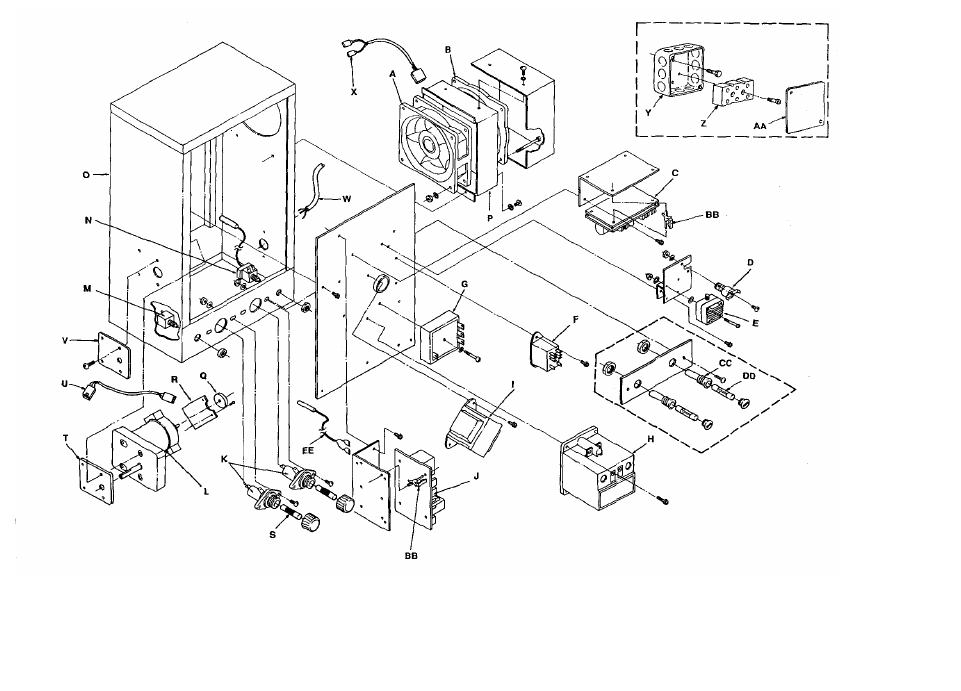
GENERAL – 1300 SERIES
LETTER P/N DESCRIPTION
A 369434 Air Duct Panel, Upper
B 369442 Finger Housing S/N 3002167 & Below
C 369436 Columnating Plate #2 (UR) – S/N 3002167 & Below
D 369445 Finger Cover, Upper Right – S/N 3002167 & Below
E 369441 Finger Cover, Lower Right – S/N 3002167 & Below
F 369439 Columnating Plate #4 (LR) – S/N 3002167 & Below
G 369435 Air Duct Panel, Lower
H 369438 Columnating Plate #3 (LL) – S/N 3002167 & Below
I 369444 Finger Cover, Lower Left – S/N 3002167 & Below
J 369446 Finger Cover, Upper Left – S/N 3002167 & Below
K 369437 Columnating Plate #1 (UL) – S/N 3002167 & Below
L 369916 Top / Front Cover Panel
M 369484 Cover Panel Assy
N 369407 Fastener & Split Ring Retainer
O 369447 Cover Panel Assembly, Right
P 369953 Flat Washer, S/S
Q 369460 Compression Spring
R 369410 Coupling Sleeve
S 370106 Flat Washer, .156 x .430
T 350259 Screw, THMS 6-32 x 3/8
U 369413 Drive Key
V 369373 Receptacle, Snap-In
W 369461 Leg, 4”
X 369945 Control Panel
Y 369429 Knob, Control
Z 369432 Switch, On – Off
AA 369449 Temperature Control Pot. Assembly
BB 369433 Potentiometer Control, Conveyor S/N 3000480 & Below
369468 Potentiometer Control, Conveyor S/N 3000481 & Above
CC 350224 Lens, Yellow
DD 369448 Cover Panel Assembly, Left
EE 369467 Pilot Light & Harness – S/N 3000481 & Above
FF 369495 Conveyor Baffle
GG 369211 Thumb Screw
HH 369451 Mounting Ring Assy.
JJ 369491 Finger Cover – S/N 3002168 & Above (4 required)
KK 369490 Columnating Plate – S/n 3002168 & Above (4 required)
LL 369488 Finger housing – S/n 3002168 & Above (4 required)
MM 369932 Facia 1-12 Minute Bake Time
370096 Facia 2-24 Minute Bake Time
370018 Facia 1-24 Minute Bake Time
NN 370095 Control Guard
OO 370097 Screw 10-32 x ¼”
November 1999 44 COUNTER TOP IMPINGER
GENERAL – 1300 SERIES PARTS BLOW-UP

November 1999 45 COUNTER TOP IMPINGER
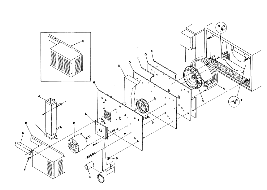
CONTROL COMPARTMENT – 1300 SERIES
LETTER P/N DESCRIPTION
A 369426 Cooling Fan – S/N 3000399 & Below
369378 Cooling Fan – S/N 3000400 & Above
B 369428 Finger Guard – S/N 3000399 & Below
369331 Finger Guard – S/N 3000400 & Above
C 369415 Conveyor Control S/N 3000480 & Below
369464 Conveyor Control – S/N 3000481 to 3007663
Except Models 1301-5, 1302-5, 1304-5, 1308-5
370017 Conveyor Control S/N 3007664 and Above and
All S/N for Models 1301-5, 1302-5, 1304-5, 1308-5
D 369431 Thermostat, Control Box Hi-Limit S/n 3000352 & Above
E 369430 Air Switch
F 369422 Relay SPST, 240V
G 369417 Time Delay Relay
H 369425 Relay Contactor Single Phase
369479 Relay Contactor 3 Pole 3 Phase
I 369427 Transformer, Conveyor Control
370241 Transformer, Conveyor Control Models 1312,1313,1314
J 369416 Electronic Temperature Control S/N 3000480 & Below
369465 Electronic Temperature Control S/N 3000481 & Above
K 369129 Fuse Holder, Model 1300,1301,1302,1307
L 369424 Conveyor Drive Motor S/N 3000480 & Below
369923 Conveyor Motor Assy. Models 1301-5,1302-5,1304-5,1308-5
369466 Conveyor Motor Assy (Assy. Includes Q,R)
S/N 3000481 & Above Except 1301-5,1302-5,1304-5,1308-5
369841 Brushes (For 369466 Motor)
M 369154 Circuit Breaker - .7Amp
N 357067 Thermostat, Capillary
O 369483 Housing Assy.
P 369482 Fan Housing
Q 369822 Magnet, 8 Pole (For 1-12 Minute Conveyor System)
370065 Magnet, 16 Pole (For 1-24 Minute Conveyor System)
R 369823 Hall Effect Sensor
S 369421 Fuse 5A, Model 1300,1301,1302,1307
T 370100 Conveyor Motor Plate, Inner
U 370040 Hall Effect Cable
V 370099 Conveyor Motor Plate, Outer
W 369414 Power Cord 30A S/n 3007818 & Below (Model 1301,1302)
370019 Power Cord 50A S/N 3007819 & Above (Model 1301,1302)
X 369536 Cooling Fan Cordset
Y 369085 Junction Box
Z 369376 Terminal Block 3 Pole
369584 Terminal Block 4 Pole
AA 369698 Cover, Junction Box
BB 369856 Stand-off, Support
CC 357107 Fuseholder
DD 369492 Fuse 5A
EE 369131 Thermocouple
November 1999 46 COUNTER TOP IMPINGER
CONTROL COMPARTMENT – 1300 SERIES BLOW - UP

November 1999 47 COUNTER TOP IMPINGER
BACK – 1300 SERIES
LETTER P/N DESCRIPTION
Color Coded on The Cold Zone
A 369418 Heating Element - 208V Red
369419 Heating Element - 240V Blue
369450 Heating Element - 220V Yellow
369455 Heating Element - 200V Orange
369456 Heating Element - 380V Violet
370105 Heating Element - 400V 1 PH Brown
369457 Heating Element - 415V Green
369475 Heating Element - 200V 3 PH Orange
369476 Heating Element - 380V 3 PH Violet
370104 Heating Element - 400V 3 PH Brown
369477 Heating Element - 415V 3 PH Green
B 369409 Main Fan
C 369408 Air Pump
D 369440 Nut, S/S ¼ - 20
E 369192 Capacitor
F 369457 Nut, 10-32
G 370041 Duct Assy
H 370020 Motor Cover Assy
I 370102 Bottom Cap, Flue Duct
J 369453 Flue Duct Assembly
K 369423 Motor, Main Fan S/N 3002137 & Below – All 1301-4,1302-4
369485 Motor, Main Fan 60 Hz S/N 3002168 & Above
370179 Motor, Main Fan 50 Hz – Models 1304-4,1305-4,1308-4
369480 Motor, Main Fan 50 Hz S/n 3002168 & Above
L 369940 Motor Mount
M 370093 Motor Plate Assy
N 369474 Insulation, Air Pump Panel
O 369936 Plenum Barrier Panel
P 369473 Insulation, Plenum Panel
Q 369935 Cover Plate, Plenum
R 369470 Insulation Seal
S 369497 Bracket, Thermostat, Left Side
T 369496 Bracket, Thermostat, Right Side
U 369459 Motor Cover Assy
November 1999 48 COUNTER TOP IMPINGER
BACK – 1300 SERIES BLOW - UP
November 1999 49 COUNTER TOP IMPINGER
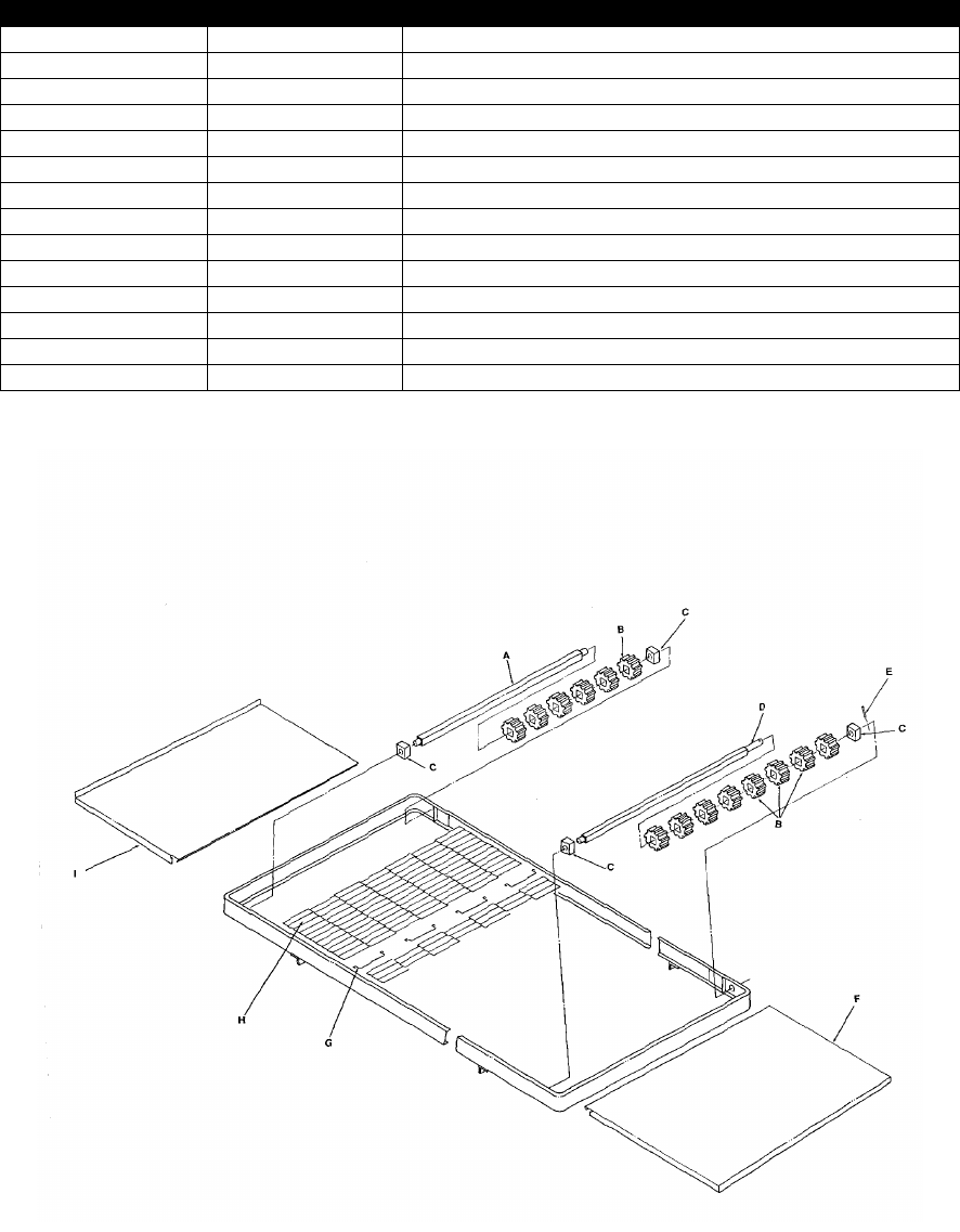
STANDARD CONVEYOR – 1300 SERIES
LETTER P/N DESCRIPTION
369443 Standard Complete Conveyor Assy. (31” Length)
A 369462 Idler Axle
B 369515 Drive Sprocket
C 369516 Conveyor Bearing
D 369463 Drive Axle
E 369471 Roll Pin, 5/32 x 7/8”
F 1343 Entry Shelf – 12”
1344 Entry Shelf – 4”
G 369412 Conveyor Splice Clip
H 369411 Conveyor Belting
370185 Conveyor Belting (1 foot section)
I 1341 Exit Shelf – 12”
1342 Exit Shelf – 4”
J 370094 Conveyor Frame Assembly
November 1999 50 COUNTER TOP IMPINGER
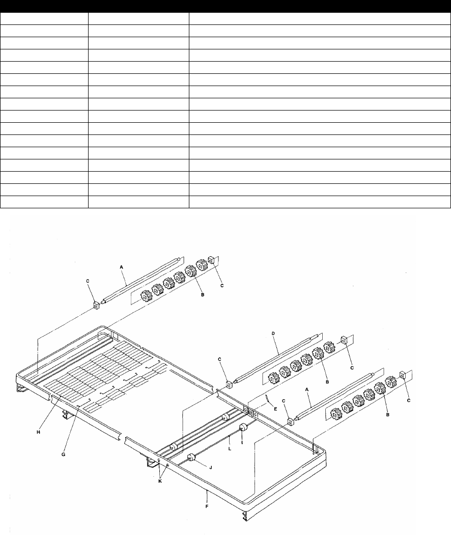
EXTENDED CONVEYOR – 1300 SERIES
LETTER P/N DESCRIPTION
369909 Extended Conveyor Assy. (49 ¾” Length)
A 369462 Idler Axle
B 369515 Drive Sprocket
C 369516 Conveyor Bearing
D 369463 Drive Axle
E 369471 Roll Pin, 5/32 x 7/8”
F 369943 Conveyor Frame, Extended
G 369412 Conveyor Splice Clip
H 369481 Conveyor Belting – Extended Conveyor
370185 Conveyor Belting (1 Foot Section)
I 369920 Retainer
J 369921 Roller, Slider Bed
K 369954 Pop Rivet S/S
L 369922 Support Rod
M 1345 Pan Stop
N 369489 Crumb Pan Assembly
