Bendix Commercial Vehicle Systems MIRD433 433.92MHz Receiver User Manual
Bendix Commercial Vehicle Systems LLC 433.92MHz Receiver
User Manual
T
A
T
T
B
L
E
L
L
O
F
C
O
C
N
T
N
E
T
T
N
T
N
S
T
T
System Overview
Using the SmarTire
Installing the SmarTire
Warranty
System Scope of Use and Warnings
4
7
13
38
41
USER GUIDE & INSTALLATION MANUAL
Thank you for purchasing a SmarTire tire pressure
monitoring system for your motorcycle. This
manual will provide you with step-by-step
instructions to help you successfully install and
operate your SmarTire system.
Though SmarTire monitors pressure and temp-
erature, it is the rider's responsibility to maintain
their tires and to react promptly when they receive
alerts and warnings. Abnormal tire inflation
pressures should be corrected at the earliest
opportunity since they can adversely affect the
motorcycle's handling characteristics and the tire's
structural integrity.
P
l
t
t
h
t
f
o
r
t
h
e
S
m
a
r
T
i
r
e
t
o
w
o
r
k
o
n
y
o
u
r
SmarTire Systems reserves the right to change the contents of this
manual at any time and without notice. The information contained in
this manual is proprietary and may not be reproduced under any
circumstances without prior written consent from SmarTire Systems Inc.
© 2004 SmarTire Systems In. All rights reserved.
710-0022
• Tires must be tubeless
• Maximum Cold Inflation Pressure
•must be below 63 psi
•Rimsmustbeatleast14"in
•diameter and 3" wide
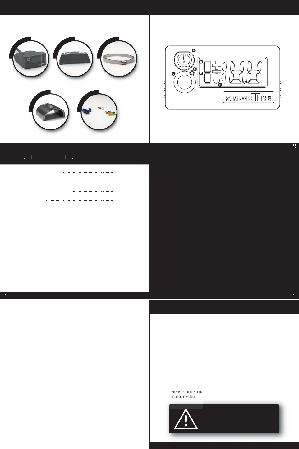
SYSTEM OVERVIEW
Display / Receiver Sensor / Transmitter Strap
SmarTire for Motorcycles consists of the following
components:
Valve Bridge Mounting Kit
x
1
x
2
x
2
x
2
x
1
SYSTEM OVERVIEW
To successfully install your SmarTire system, you
will need:
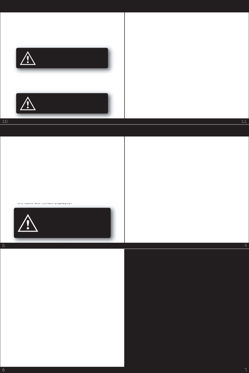
A. Warning Icon
B. On Light
C. Button
D. Front Tire Icon
E. Rear Tire Icon
F. Temperature Indicator
SYSTEM OVERVIEW
You are operating your motorcycle
in a dangerous condition. Stop and
make repairs.
You are operating your motorcycle
in a dangerous condition. Stop and
make repairs.
SmarTire actively monitors and displays tire
pressure, pressure deviation and tire temperature.
The system will warn you if your tire pressures are
too low or tire temperatures are too high in order
to reduce accident risk, maximize performance,
increase tire life and improve fuel efficiency.
Getting Started
When your motorcycle is started, SmarTire will
power up, briefly flash the tire icons and display
dashes indicating that it is waiting for tire data.
When the motorcycle is ridden over 6 mph (10
kph), SmarTire will begin to receive tire data. When
all tire data has been successfully received and the
system is operating normally, the front and rear
t
i
r
e
i
c
o
n
s
w
i
l
l
r
e
m
a
i
n
d
i
s
p
l
a
y
e
d
USING THE SMARTIRE USING THE SMARTIRE - continued.
USING THE SMARTIRE - continued.USING THE SMARTIRE - continued.
Press the button and SmarTire automatically
displays inflation pressure, pressure deviation and
temperature for both tires. To quickly toggle
through the tire data, press the button repeatedly.
Alert Modes
The alert icon will activate whenever tire pressure
drops below or tire temperature exceeds the factory
preset limits. When the tire condition has been
corrected, the alert icon will turn off. In all cases, a
tire icon will indicate which tire is affected. SmarTire
has three alert modes:
The Pressure / Temperature Relationship
When a motorcycle is ridden, the tires heat up and
the actual pressure inside the tire increases. When
displaying pressure, SmarTire displays actual
pressure values without compensating for pressure
changes caused by temperature variations.
SmarTire also displays Pressure Deviation, which is
the difference between the calculated pressure that
should be in the tire at the current tire temperature
and the actual measured tire pressure. For example,
a Pressure Deviation value of -3 indicates that you
should increase that tire's pressure by 3 psi. The
Pressure Deviation is accurate regardless of the
temperature of the tire.
For a more technical description of temperature
compensation, please visit our website at
www.smartire.com.
The Pressure Deviation Alert is set to trigger if
the pressure in either your front or rear tire is
15% below or above the temperature
compensated cold or recommended inflation
pressure (see Pressure / Temperature Relation-
ship). The alert icon will flash and the pressure
deviation is displayed.
•
The Low Pressure Alert is set to trigger if the
pressure in either tire falls below 25% of the
cold inflation pressure. The alert icon will
activate and the tire pressure is displayed. Note:
The warning icon and pressure deviation will
remain illuminated until air is added to the flat
tire.
•
The High Temperature Alert is set to trigger if
the temperature in either tire exceeds 176°F
(80°C). The alert icon will flash and the tire
temperature is displayed.
•
SmarTire starts to receive tire data
only when your motorcycle reaches 6
mph (10 kph). If you want to access
tire data while stopped, for example
when filling tires at a service station,
do not turn off your motorcycle.
USING THE SMARTIRE
INSTALLING THE SENSORS
In this section, you will learn how to mount a
sensor on a rim. Please read this section carefully
a
d
f
o
l
l
o
h
l
h
a
t
y
o
u
d
o
n
o
Wrap the strap
around the
rim and mark
1" past the
worm gear
for cutting.
You may want to temporarily adjust tire pressures
to safely carry a passenger or additional loads.
This should always be done as per the motorcycle
owner's manual. If the motorcycle tire pressure
settings are changed, SmarTire must learn the new
values. To update the cold inflation pressure:
USING THE SMARTIRE - continued.
Adjust the pressures in both the front and rear
tires to the desired values when the tires are
cold.
1.
Turn on the motorcycle and immediately press
and hold the button until the letters 'CP' are
displayed.
2.
Ride the motorcycle above 6 mph (10 kph). The
new settings will be automatically saved and the
unit will exit the 'Pressure Adjust' mode.
3.
INSTALLING THE DISPLAY
- continued.
Wire the display/receiver to the motorcycle
connecting the positive wire (red) to the
power supply through an ignition keyed
circuit and the negative wire (black) to
ground. For some motorcycles, it is easiest to
connect to an ignition keyed circuit through
the fuse box.
4.
Using the included double sided tape, adhere
the display to the motorcycle.
3.
INSTALLING THE DISPLAY
In this section, you will learn how to mount and
wire the SmarTire display/receiver.
The mounting location must be
perfectly clean to ensure a rigid
bond between the display and the
motorcycle.
Find a suitable location to mount the display
(use either top or bottom surface as needed).
Ideally, the location should be:
• a sheltered area within the operator's
•normal field of vision, and
• an area that is not normally removed
•during routine servicing and maintenance.
1.
Clean the mounting surface thoroughly.2.
TOOLS REQUIRED
To successfully install your SmarTire system, you
will need:
5
/
1
6
(
8
)
D
i
M
C
i
i
T
l
x
1
x
2
x
2
Tire Pressure Gauge Cleaning Product
INSTALLING THE SMARTIRE
INSTALLING THE SENSORS
- continued.
4. Install the strap mounted sensor on
the rim in the lowest point of the
drop center well.
If the width of the wheel requires
the strap to pass over the valve,
elevate the strap using the
supplied valve bridge.
If there is no valve recession in the drop center
well, the bottom of the valve bridge may block a
rubber valve. In this case, replace the rubber
valve with a metal valve. If a metal valve is used
and its head is recessed fully below the surface
of the rim, the valve bridge is not required.
Drop
Center Well
Strap
Valve
Bridge
Valve
INSTALLING THE SENSORS
- continued.
• the sensor is located directly opposite the
valve stem, and
• the worm gear is 1" away from the sensor.
Orient the components on the rim so that:5.
Sensor
Worm Gear
Strap
Valve
Valve Bridge
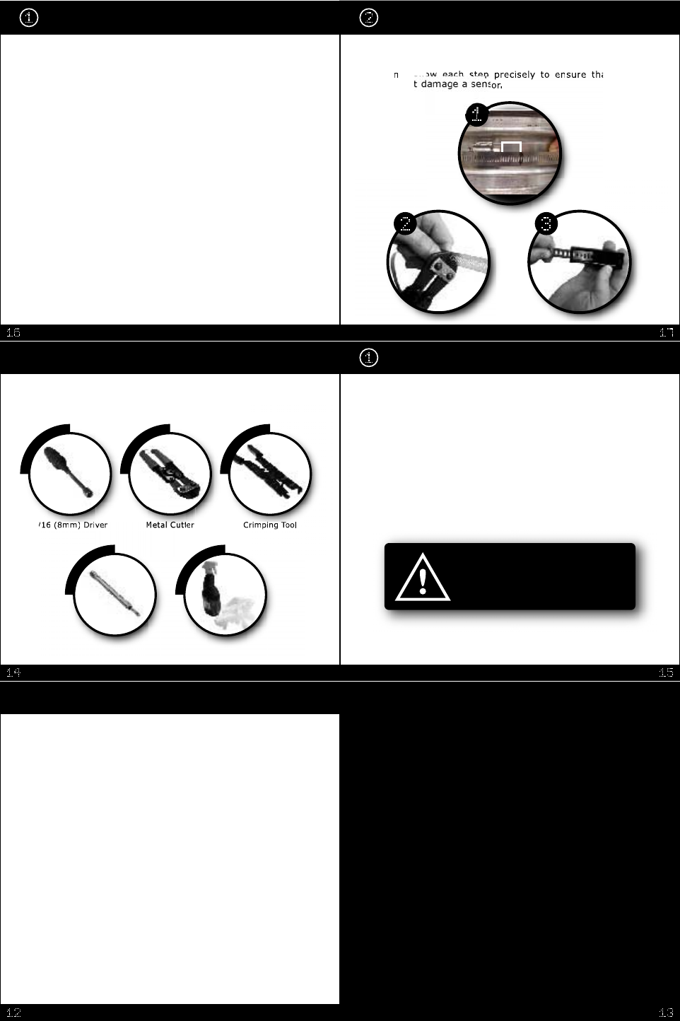
MOUNTING THE TIRE
Please read this section carefully
and follow each step precisely to
ensure that you do not damage a
sensor.
In this section, you will learn how to mount the tire
without damaging the sensor.
Place the rim on the
turntable of a tire-
mounting machine so
that the mount head is
at 12 o'clock with the
sensor at 7 o'clock.
INSTALLING THE SENSORS
- continued.
Han
t
i
g
h
t
e
n
t
h
e
w
o
r
m
g
e
a
r
u
n
t
i
l
t
h
e
m
o
u
n
t
e
d
sen
n
.
6.
Apply the supplied rim label on the outside of the
rim flange to indicate the location of the sensor.
MOUNTING THE TIRE - continued.
Starting from the mount head, manually depress
the lower bead of the lubricated tire over the rim
flange and into the drop center well until its
pinch point is approximately 3" (7.5 cm) before
the sensor.
2.
Note: The pinch point (also known as the
traction point) is the position on the rim where
the tire bead encounters resistance when trying
to slip over the rim flange.
MOUNTING THE TIRE - continued.
l
o
w
the pinch
o
r
t
he sensor
m
a
y
b
e
b
r
o
k
e
n
.
5
.
F
i
n
i
s
h
i
n
s
t
a
l
l
a
t
i
o
n
a
s
n
o
r
m
a
l
.
(
S
e
a
t
t
he beads,
install the valve core, inflate to the
recommended cold inflation pressure, balance
tires and mount wheels on the motorcycle).
Advance the turntable
usingthemountheadto
guide the rest of the
bottom bead over the
flange and onto the
rim. When done
properly, the bead
will slip over the
flange without
contacting the sensor.
Compare the pressure values that are displayed
for the front and rear tires to the pressures the
tires were inflated to. When programmed
correctly, the display will show the same
pressure values that the tires were inflated to.
3.
The SmarTire System is extremely
accurate at measuring tire pressure.
If the pressure values displayed are
slightly different than the manual
gauge, it is usually because the
SmarTire is more accurate.
TESTING THE SYSTEM - continued.
PROGRAMMING THE RECEIVER
- continued.
Finally, press the button on the display to save
the settings. Your SmarTire will now be
programmed and ready for use.
4.
Now, spin the front tire approximately 6 mph (10
kph) to provoke a data transmission from the
sensor. The captured data will then be set as the
front tire value.
If the transmission was successful, the display
will toggle between the front and rear tire
pressures.
3.
TESTING THE SYSTEM
Accelerate the motorcycle forward to a speed of
at least 6 mph (10 kph) to activate the sensors,
causing them to transmit tire pressure and
temperature data. When transmissions are
received from the sensors, the display will show
the inflation pressure for each tire and then go
blank, showing only the front and rear tire icons.
2.
Starting with the motorcycle off, power up the
SmarTire by turning on the motorcycle. When
first powered on, SmarTire will display
alternating front and rear tire icons with dashes
for pressure readings as it searches for data
from the two wheels.
1.
In this section, you will learn the best method of
testing a newly installed SmarTire to ensure that it
is programmed properly and operating normally.
Though highly unlikely, it is possible that your
SmarTire captured data from a near-by sensor
other than the one intended during programming.
To test the system:
PROGRAMMING THE RECEIVER
- continued.
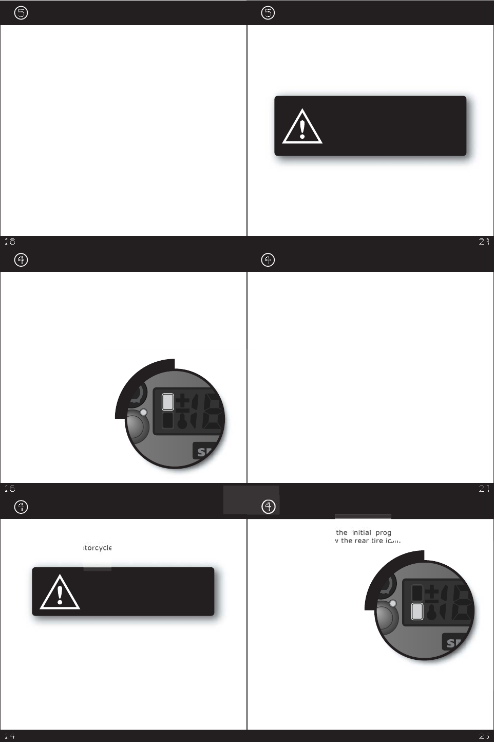
Upon entering
r
a
m
m
i
n
g
m
o
d
e
,
t
h
e
display will sho
w
t
h
e
o
n
If the display does not show
the rear tire icon but
powers on normally, the
unit has already been
programmed. To re-
enter the initial
programming mode,
first, turn off the
motorcycle. Then,
turn the motorcycle
back on to its accessory
position while
simultaneously holding
down the button on the
display until it shows the rear
tire icon (approx.. 2 seconds). The
unit will then be in programming mode ready for
reprogramming.
To toggle between programming the front and rear
tire first, press the button on the display.
PROGRAMMING THE RECEIVER
- continued.
2. Make sure the wheels have not been disturbed
for at least 60 seconds. With the motorcycle on
its center stand or a bike jack, spin the rear tire
approximately 6 mph (10 kph) to provoke a data
transmission from the sensor. The data along
with a sensor ID number will be captured by the
display/receiver and set as the rear tire value.
Once the receiver has successfully captured the
data transmission, the
display will briefly show
the pressure of the
rear tire. Then, the
display will switch
to showing the
front tire icon;
ready to receive
data for the front
tire.
In this section, you will learn how to calibrate the
Display/Receiver to the sensors installed in the
t
i
r
e
s
o
f
t
h
e
m
o
.
Turn the bike on to its accessory position and
SmarTire will check to see if it has been
programmed. On a new installation, the display/
receiver will automatically enter its initial
programming mode when powered on, ready to
receive the sensor ID and tire pressure for the
REAR tire.
1.
PROGRAMMING THE RECEIVER
Make sure that both tires are set to
their correct cold inflation pre-
ssures in advance of programming
the display.
TROUBLE SHOOTING
- continued.
ACTION:
Turn the motorcycle off and then back on to its
accessory position to reset the SmarTire. If the
problem clears itself, check for an excessive
voltage drop during engine startup. If the problem
reoccurs, the display will need to be replaced.
AAfter about 20 minutes of riding, the display
shows an 'E1' System Alert and hasn't received
a transmission from one of the sensors.
CAUSE:
A sensor has stopped transmitting.
ACTION:
If tire replacement or repair has preceded the
appearance of the error, check to confirm that
the sensor was reinstalled and not damaged. If
no tire related work was recently done, the
sensor may need to be replaced. If the sensor
was recently replaced, the display will need to
be programmed to the new sensor (see
Installation Step 4: Programming the Receiver
on page 24).
5.
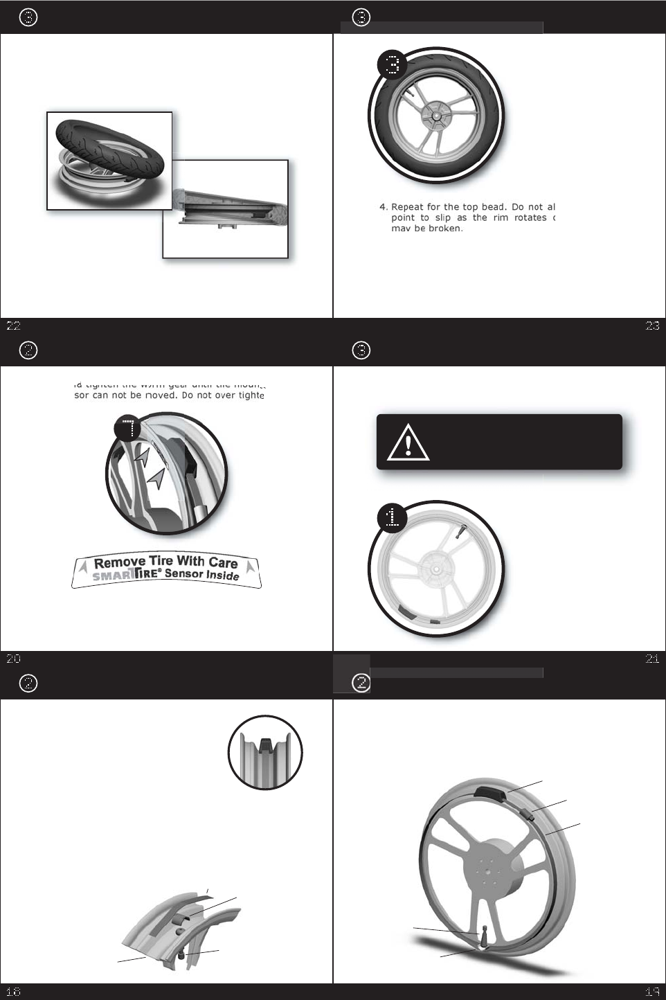
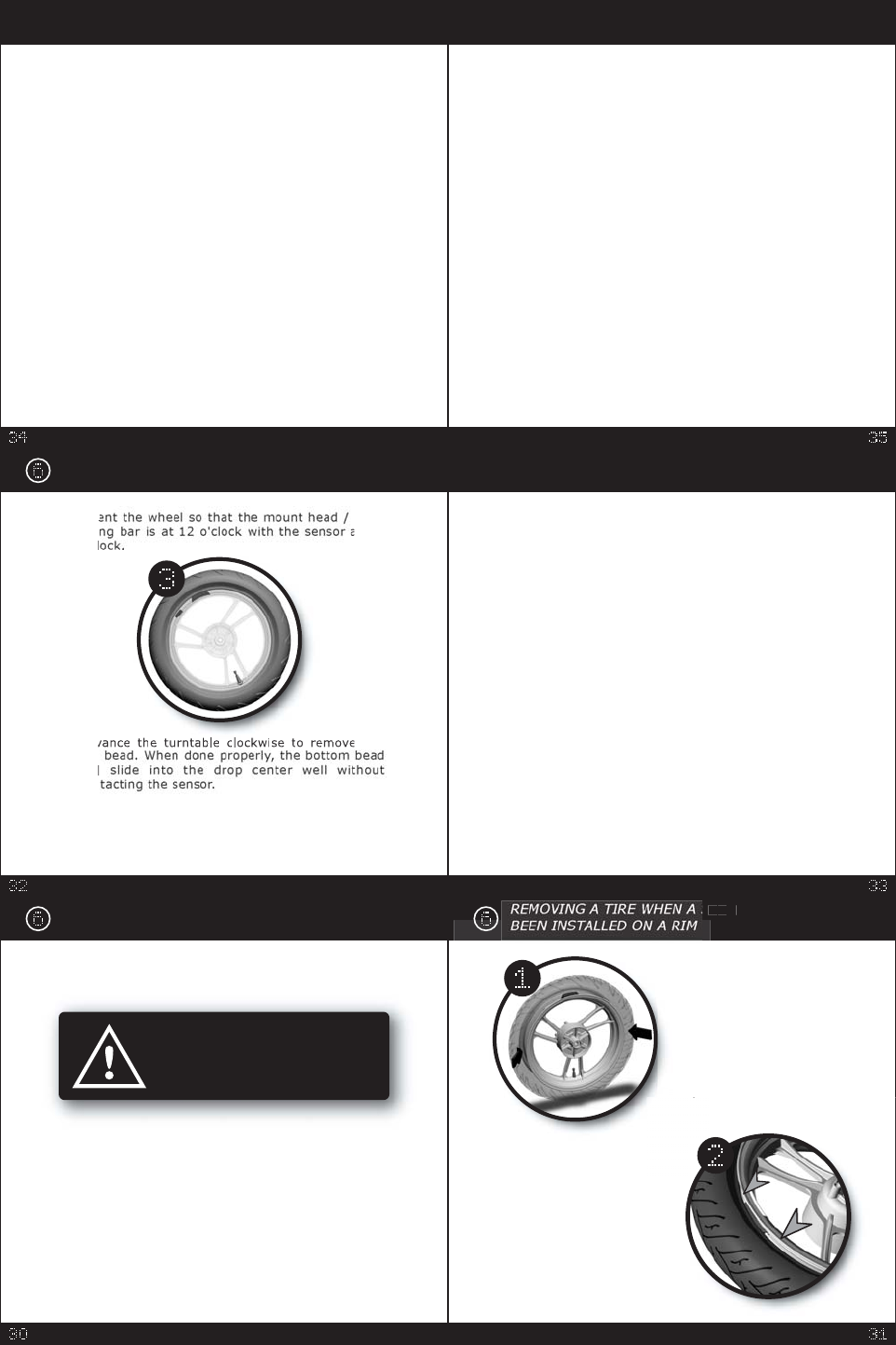
REMOVING A TIRE WHEN A SENSOR HAS
BEEN INSTALLED ON A RIM
Follow these instructions
carefully to ensure you do not
damage the sensors.
In this section, you will learn how to remove a tire
from a motorcycle rim that has a SmarTire sensor
installed on it.
Make sure you know the location of the sensor
before unseating the beads of the tire. The rim
mounted decal should indicate the approximate
location of sensor.
If there is no rim mounted decal, the sensor should
be mounted directly opposite the valve stem.
CAUTION:
TROUBLE SHOOTING
Display does not power up when the motorcycle
is turned on.
CAUSE:
The display is not receiving power, or proper
polarity from the power source.
ACTION:
Confirm that power cable is connected to the
correct polarity sources and electrical power is
actually present at the connector when the key
is turned to the 'on' / 'accessory' position.
Inspect the power supply cable for any cuts that
may effect continuity.
1.
Display powers up but no transmissions are
received from the sensors.
CAUSE:
The display/receiver captured data from sensors
other than those installed on the motorcycle.
2.
TROUBLE SHOOTING
- continued.
ACTION:
Re-program the display/receiver (see Installation
Step 4: Programming the Receiver on page 24).
Display initiates a Pressure Deviation Alert
shortly after beginning a ride.
CAUSE:
Tire pressure is 15% higher or lower than the
programmed cold inflation pressure setting.
ACTION:
Inflate/deflate the affected tire to the motor-
cycle's correct cold inflation pressure.
3.
When powered on, the Warning Icon flashes and
the display shows an E2, E3, E4, or E5 System
Alert.
CAUSE:
Electronic components are not powering up
properly due to component malfunction or
insufficient voltage.
4.
S
E
N
E
E
S
O
R
HAS
After removing the wheel
from the motorcycle and
deflating the tire
completely, unseat the
beads with the bead
breaker shoe 90° from
the valve stem (away
from the sensor which is
located opposite the valve
s
t
e
m
)
.
Place the wheel on the
turntable of a tire
mounting machine and
depress the sidewall of
the tire to verify the
exact location of the
sensor.
REMOVING A TIRE WHEN A SENSOR HAS
BEEN INSTALLED ON A RIM
A
d
v
e
t
h
e
to
p
wi
l
l
con ac ng e sensor.
4.
Repeat for the bottom bead. Prior to tire
installation, check the sensor for correct
positioning and strap tightness.
5.
O
r
i
e
b
e
a
d
lif
t
i
a
t
1
1
o'
c
l
3.

WARRANTY: USA
This Warranty covers substantial manufacturer's defects in workmanship and
materials only. It does not cover any unit that is damaged beyond normal usage,
was not properly installed, was subjected to chemical contact, or other acts or
omissions not sanctioned by the Owner's Manual.
All components are covered for one (1) year and unlimited mileage following the
date of installation.
The SmarTire® warranty will be honoured by any authorized SmarTire® dealer.
The owner is required to provide dated proof of purchase. The authorized dealer
will determine if there is a warrantable condition associated with materials and/or
manufacturing workmanship. If a warrantable condition exists, the component will
be replaced free of charge, shipping prepaid. The owner is responsible for any
labor and installation charges.
A completed Warranty Claim Form must be sent, postage prepaid, with the
defective unit to SmarTire USA Inc., PMB 309, 566 White Pond Dr. C., Akron, OH
44320-1116 USA. Phone: 330-497-0236 or 888-982-3001.
The Warranty does not include any further obligation whatsoever, including but not
limited to actual installation of the replacement unit on the customer's motorcycle.
All other Warranties, express or implied, are disclaimed. All collateral agreements,
which purport to modify this Limited Warranty are of no effect. The absolute limit
of liability is the purchase price of the unit. SmarTire Systems Inc. is not liable for
any direct, consequential, indirect, or punitive damages of any kind.
SOME STATES DO NOT ALLOW LIMITATIONS ON THE VALIDITY OR LENGTH OF
IMPLIED WARRANTIES, SO THE ABOVE LIMITATIONS MAY NOT APPLY TO YOU.
SOME STATES DO NOT ALLOW THE EXCLUSION OR LIMITATION OF INCIDENTAL
OR CONSEQUENTIAL DAMAGES, SO THE ABOVE LIMITATION OR EXCLUSION MAY
NOT APPLY TO YOU. THIS WARRANTY GIVES YOU SPECIFIC LEGAL RIGHTS, AND
YOU MAY HAVE OTHER RIGHTS WHICH VARY FROM STATE TO STATE.
WARRANTY: CANADA
This Warranty covers substantial manufacturer's defects in workmanship and
materials. It does not cover any unit that is damaged beyond normal usage,
was not properly installed, was subjected to chemical contact, or other acts or
omissions not sanctioned by the Owner's Manual.
All components are covered for one (1) year and unlimited mileage.
The SmarTire® Warranty will be honoured by any authorized SmarTire®
dealer. The owner is required to provide dated proof of purchase. The
authorized dealer will determine if there is a warrantable condition associated
with materials and/or manufacturing workmanship. If a warrantable condition
exists, the component will be replaced free of charge, shipping prepaid, if
within the applicable warranty period. The owner is responsible for any labour
and installation charges.
This notice must be sent, postage prepaid, with the defective unit to SmarTire
Systems Inc., 13151 Vanier Place, Suite 150, Richmond, British Columbia,
Canada, V6V 2J1. Phone: 604-276-9884.
The Warranty does not include any further obligation whatsoever, including
but not limited to actual installation of the replacement unit on the customer's
motorcycle.
ALL OTHER WARRANTIES AND CONDITIONS, EXPRESS OR IMPLIED,
INCLUDING WARRANTIES AND CONDITIONS FOR MERCHANTABILITY,
DURABILITY OR FITNESS FOR PURPOSE, ARE DISCLAIMED. ALL COLLATERAL
AGREEMENTS, WHICH MODIFY THIS SOLE WARRANTY ARE OF NO EFFECT.
SMARTIRE SYSTEMS INC. IS NOT LIABLE FOR ANY DIRECT, CONSEQUENTIAL,
INDIRECT OR PUNITIVE DAMAGES. THE ABSOLUTE LIMIT TO LIABILITY IS
THE PURCHASE PRICE OF THE UNIT.
REPLACEMENT PART NUMBERS
Need to replace a part of your SmarTire System?
Check the list below to identify the part number of
the component you need.
Display / Receiver: USA
Display / Receiver: Europe
Display / Receiver: UK
Display / Receiver: Canada
Sensor / Transmitter
Strap
Valve Bridge
Mounting Kit (motorcycle)
084.9001
085.9001
086.9001
000.0000
062.1005
062.1002
062.1006
062.1007
.......................
...................
.........................
...................
...........................
................................................
......................................
....................
TECHNICAL SPECIFICATIONS
DISPLAY / RECEIVER
Power Consumption
Operating Temperature
Operating Humidity
Size
Weight
SENSOR TRANSMITTER
Battery Life
Operating Temperature
Size
Weight
Operating Humidity
Frequency
Maximum Operating Pressure
Pressure Accuracy
Activation
60 mA
-40°F - +185°F
(-40°C - +85°C)
100%
2.5" x 1.65" x 0.9"
(6.3 x 4.2 x 2.3 cm)
1.04 oz (29.3 g)
7 years (approx.)
-40°F - 257°F
(-40°C - 125°C)
3.26" x 1.14" x 0.98"
(8.3 x 2.9 x 2.5 cm)
1.41 oz (40 g)
100%
433.92 MHz
78 psi (5.35 bar)
+/-1.5 psi (0.1 bar)
Vehicle Motion greater
than 6 mph / 10 kph
WARRANTY: EUROPE
SmarTire Europe Limited ("SmarTire") hereby warrants that this SmarTire
wireless tyre pressure monitoring system shall be free from material defects
in workmanship and/or materials until the expiry of twelve months from its
purchase by the end user and unlimited mileage, EXCEPT WHERE any such
defect has been caused by:
1. Improper installation;
2. Improper or non-normal use;
3. Contact with any corrosive or otherwise harmful substance; or
4. Any other act or omission not sanctioned by the Owner's manual or any
failure to follow any other reasonable instructions given by SmarTire in
relation to the system.
The above warranty will be honoured by the retailer from which it was
purchased, provided that the owner can provide dated proof of purchase.
The retailer shall at SmarTire's cost send any unit which is defective as
described in the above warranty to SmarTire at Park 34, Didcot, Oxfordshire
OX11 7WB, England.
In the event that any defect in the unit is covered by the above warranty,
SmarTire will replace the affected components free of charge, shipping
prepaid. The owner shall be responsible for any labour and installation costs
incurred in removing the defective parts and/or installing the replacements.
SAVE AS SET OUT HEREIN SMARTIRE SHALL HAVE NO FURTHER LIABILITY OR
OBLIGATION UNDER THE ABOVE WARRANTY. THIS WARRANTY SHALL BE
GOVERNED AND CONSTRUED IN ACCORDANCE WITH ENGLISH LAW.
YOUR STATUTORY RIGHTS ARE NOT AFFECTED.
SYSTEM SCOPE OF USE & WARNINGS
The SmarTire® System and Tire Maintenance
This system is a sensing device designed to identify and display tire operating
data and activate an alert or warning when pressure or temperature
irregularities are detected. It is the responsibility of the driver to react
promptly and with discretion to alerts and warnings. Abnormal tire inflation
pressures should be corrected at the earliest opportunity.
System Installation and Usage
Use of the SmarTire® system requires that it has been properly installed and
programmed by qualified personnel according to SmarTire Systems Inc.
documentation. This includes the Owner's Manual and any supplementary
installation instructions included with system components.
Warnings
1.
2.
3.
4.
Use of Chemicals
Temporary resealing or reinflation products containing internal sealers or
propellants in any tire/wheel assembly may adversely affect the operation of
the sensor/transmitters.
When an alert or warning condition is detected, reduce vehicle speed to an
appropriate safe level and proceed to a safe stopping location or facility
where the tire can be inspected and serviced.
The pressure deviation alert indicates that the pressure has dropped a
selected amount below the required pressure for that level of tire
temperature.
The low pressure warning indicates that the air pressure has dropped to a
selected minimum level.
The high temperature warning indicates that the contained air temperature
has exceeded the selected maximum. A tire temperature buildup can be
caused by a number of factors including severe under inflation, hard
sustained braking, vehicle overload and sustained high speeds.

FCC NOTICE
This device complies with Part 15 of the FCC Rules. Operation is subject to the
following two conditions: (1) this device may not cause harmful interference,
and (2) this device must accept any interference received, including
interference that may cause undesired operation.
This equipment has been tested and found to comply with the limits for a
Class B digital device, pursuant to Part 15 of the FCC Rules. These limits are
designed to provide reasonable protection against harmful interference in a
residential installation. This equipment generates, uses and can radiate radio
frequency energy and, if not installed and used in accordance with the
instructions, may cause harmful interference to radio communications.
However, there is no guarantee that interference will not occur in a particular
installation.
If this equipment does cause harmful interference to radio or television
reception, which can be determined by turning the equipment off and on, the
user is encouraged to try to correct the interference by one or more of the
following measures:
Reorient or relocate the receiving antenna.
Increase the separation between the equipment and receiver.
Connect the equipment into an outlet on a circuit different from that to which
the receiver is connected.
Consult the dealer or an experienced radio/TV technician for help.
Changes or modification to this device without the express approval of
SmarTire Systems Inc, may void the user's authority to use this device.
EUROPEAN REGULATIONS
This device complies with all European Electromagnetic compatibility
regulations (95/54/EC and EN 300 220-1). The equipment has been tested
and found to comply with the above regulations, and in addition it meets the
requirements for low powered transmitters/receivers as defined by the
relevant radio approval authority. The regulations are designed to provide
reasonable protection against harmful interference or susceptibility. Changes
made to this device without the express approval of SmarTire Europe Ltd.
may void the user's authority to use this device.