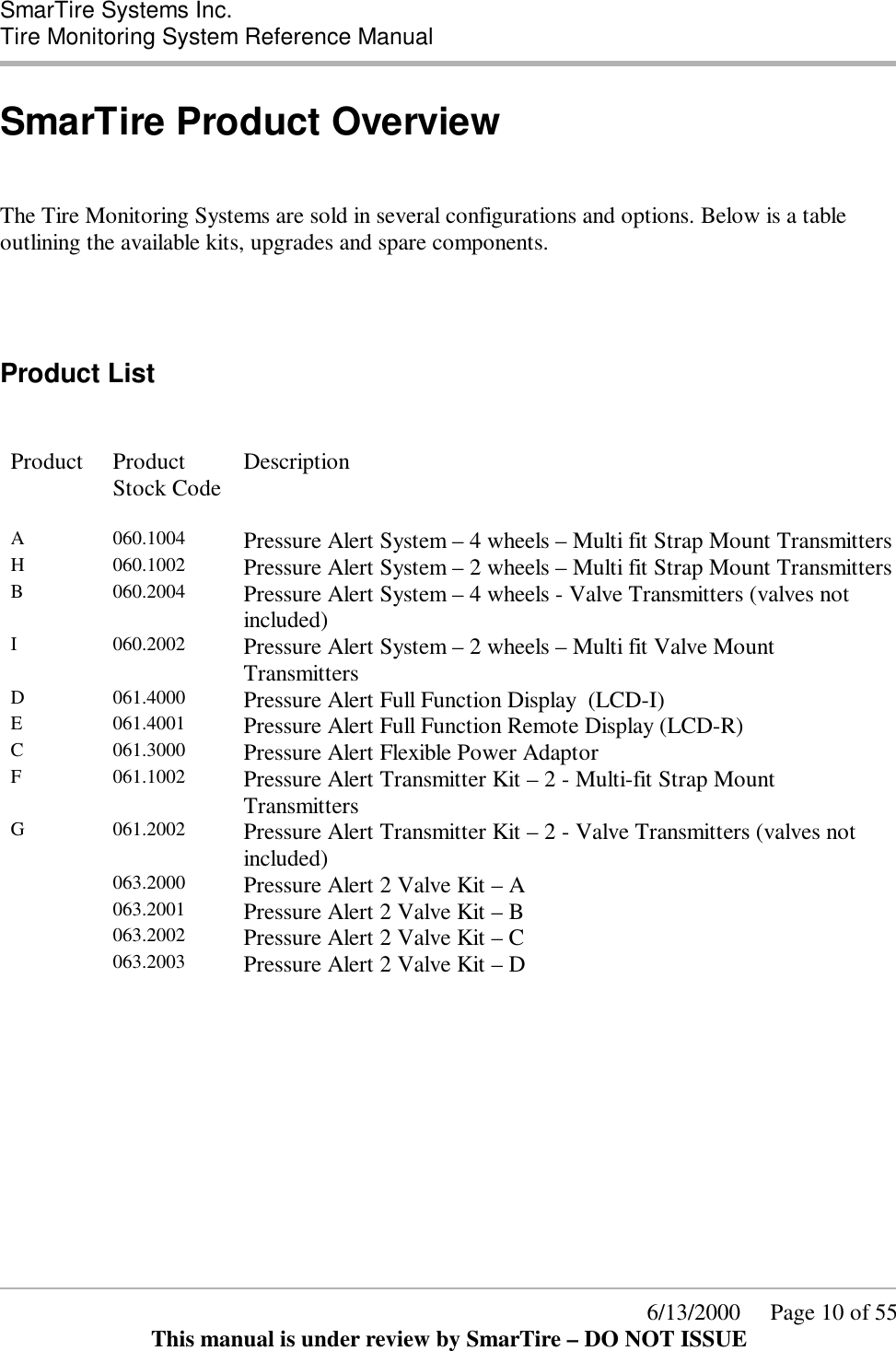
Bendix Commercial Vehicle Systems RX433R-2 Receiver For a Wireless Tire Monitoring System User Manual GENII usermanual
Bendix Commercial Vehicle Systems LLC Receiver For a Wireless Tire Monitoring System GENII usermanual
Exhibit 8 User Manual please see Page 5 for FCC stmt
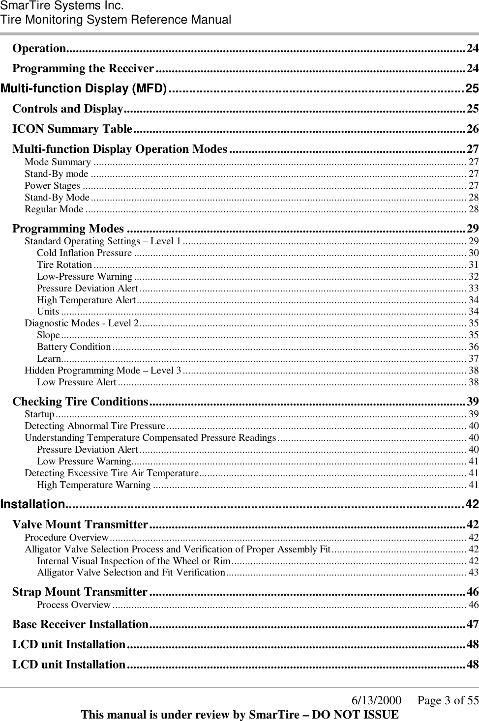
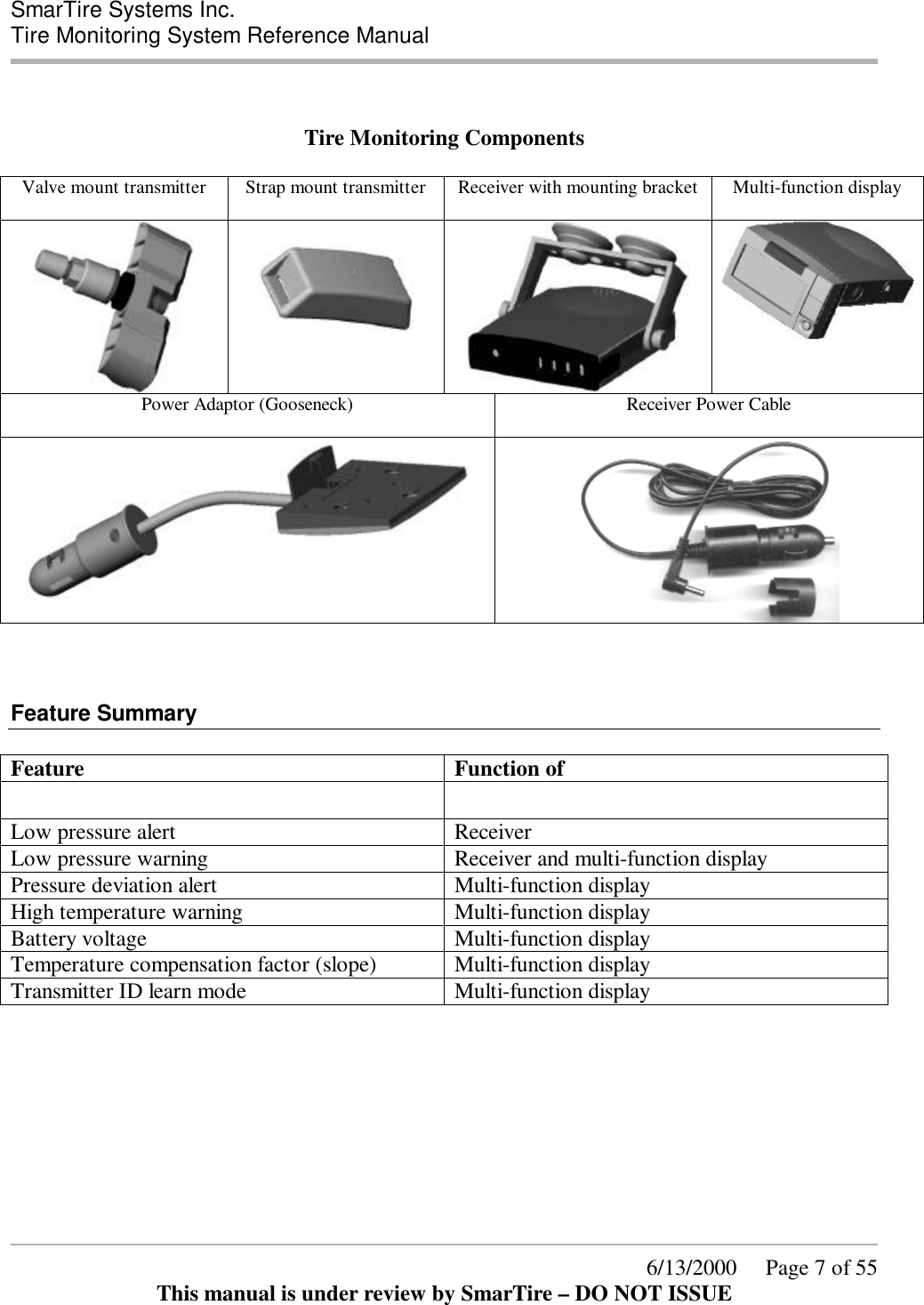
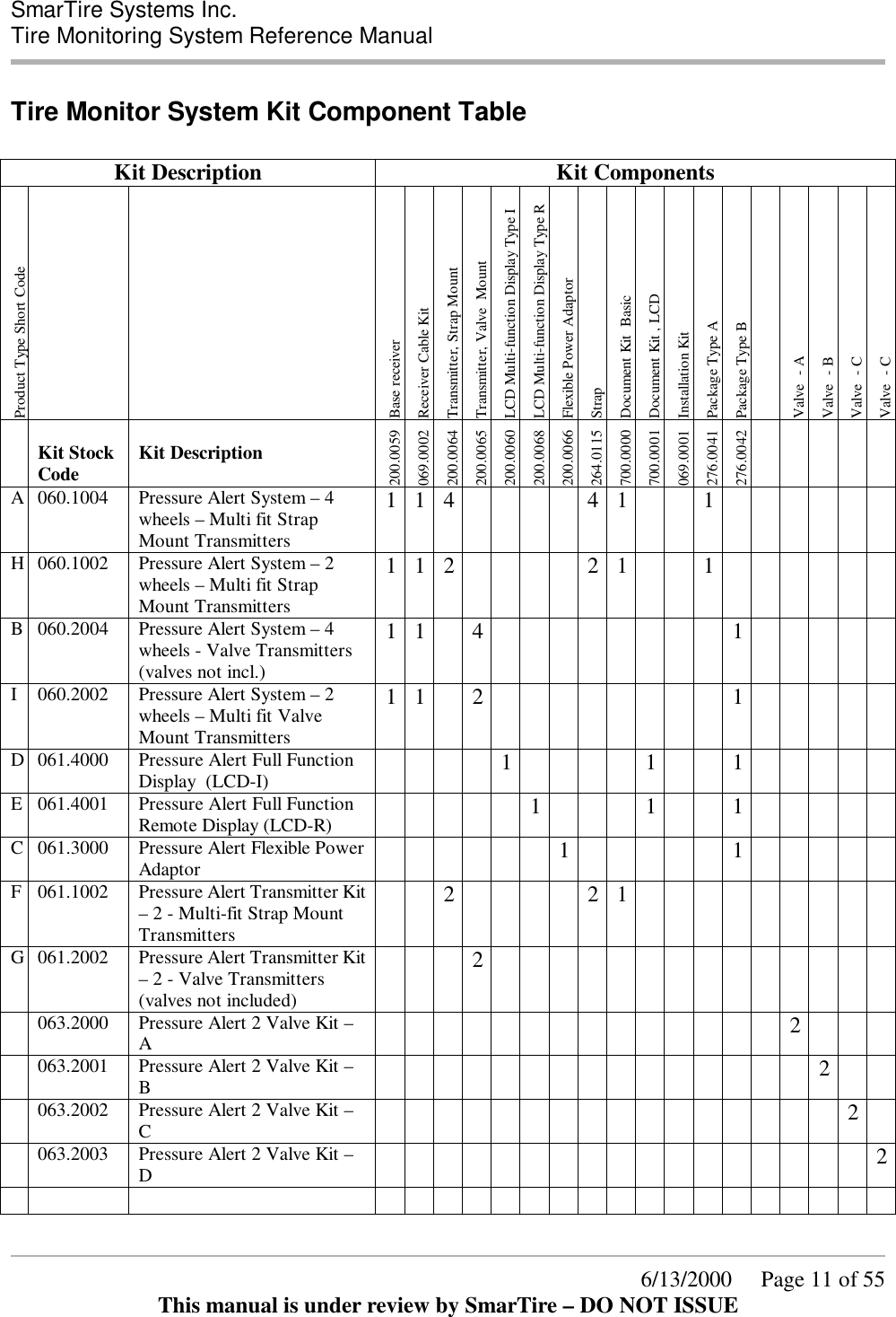
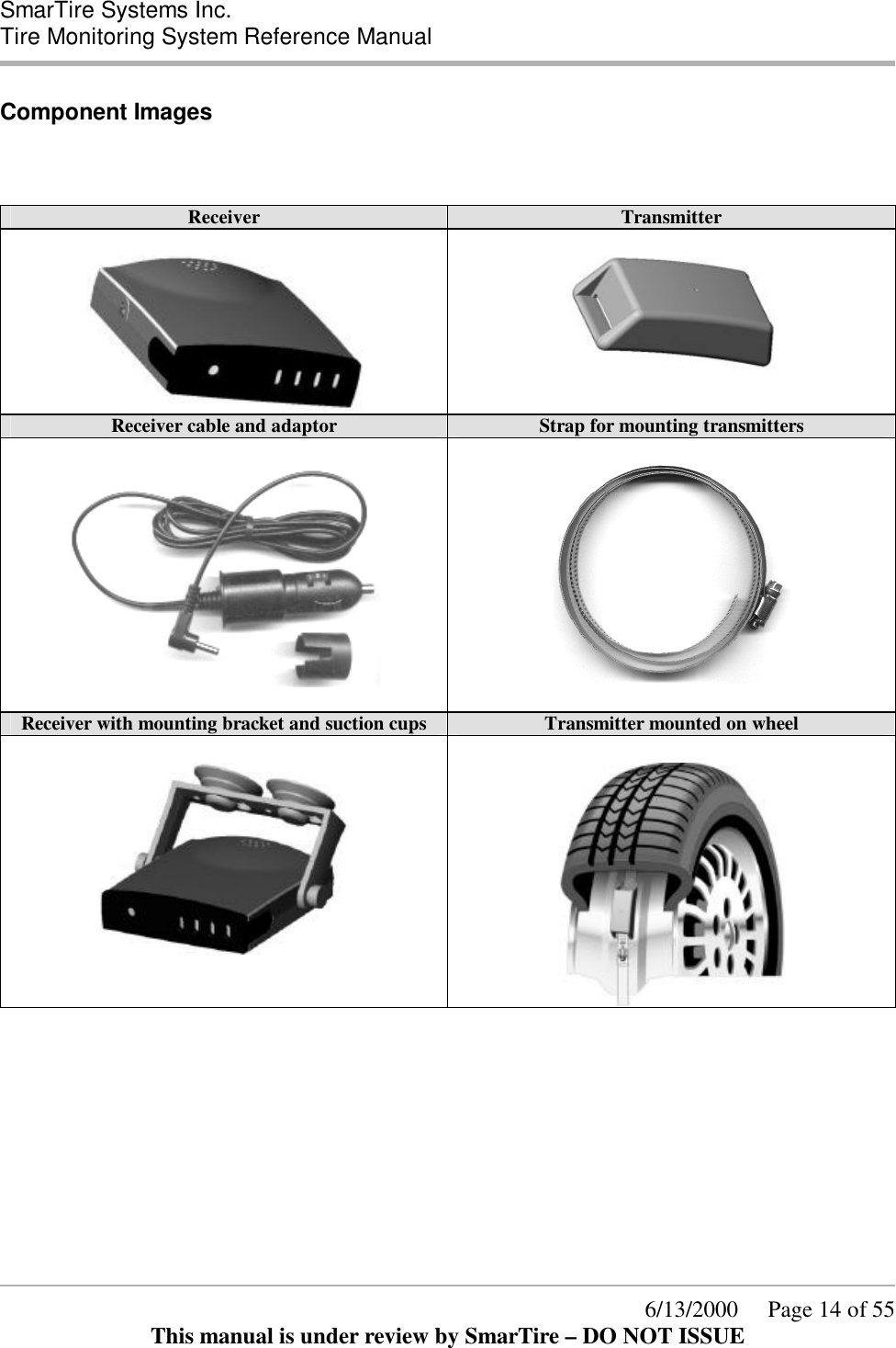
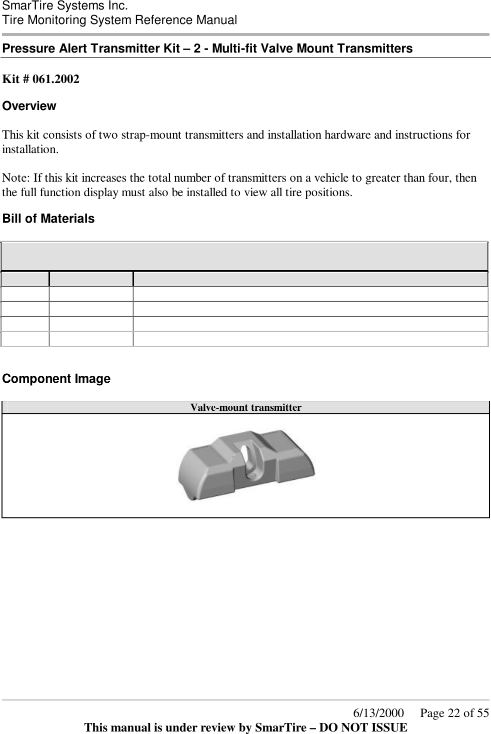
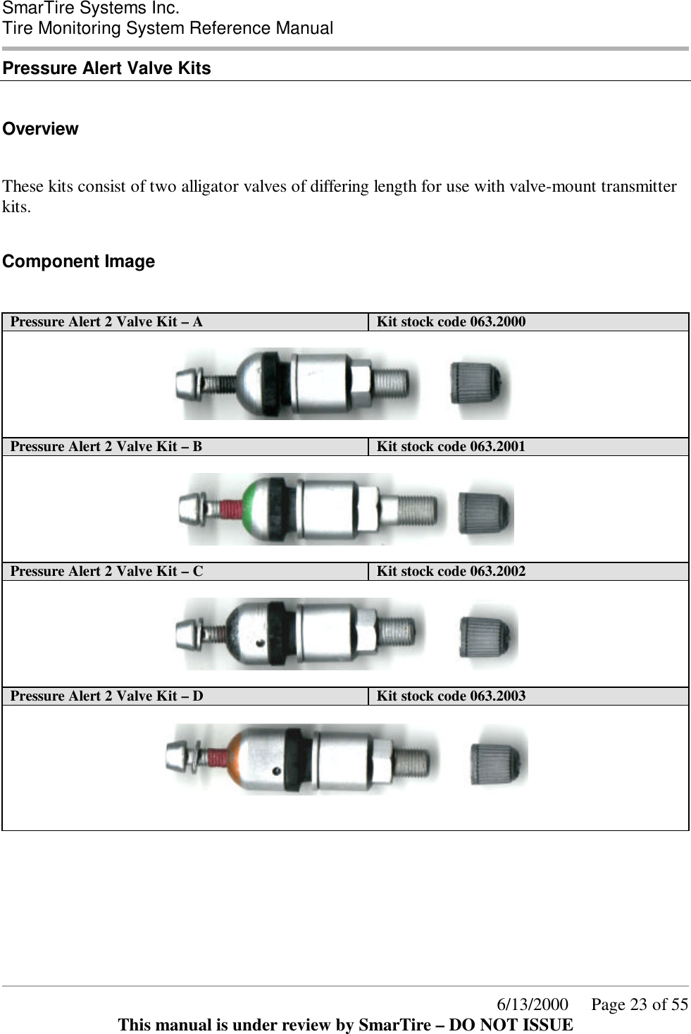
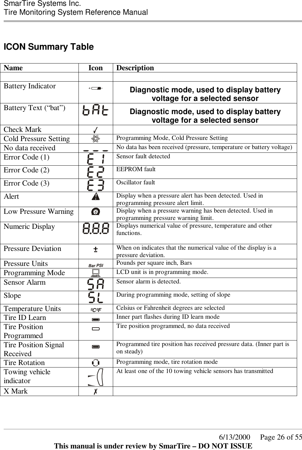
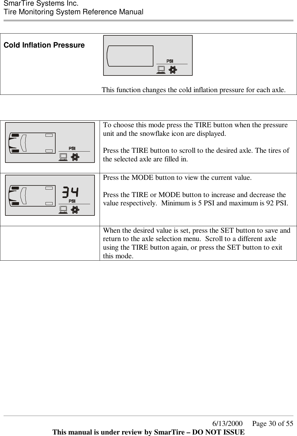
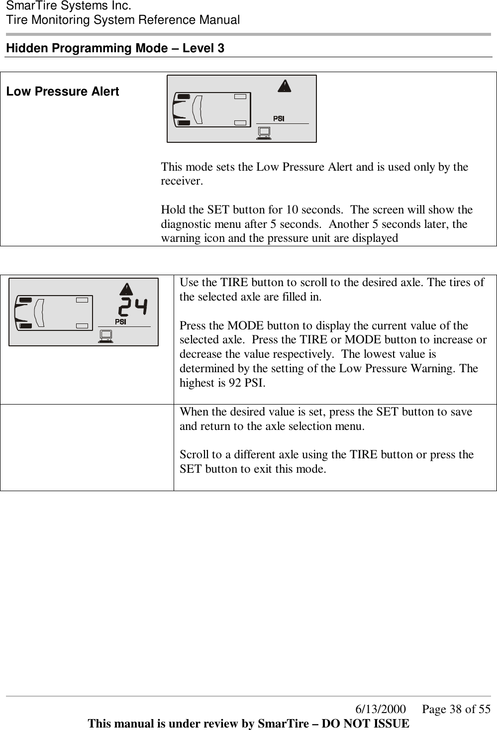
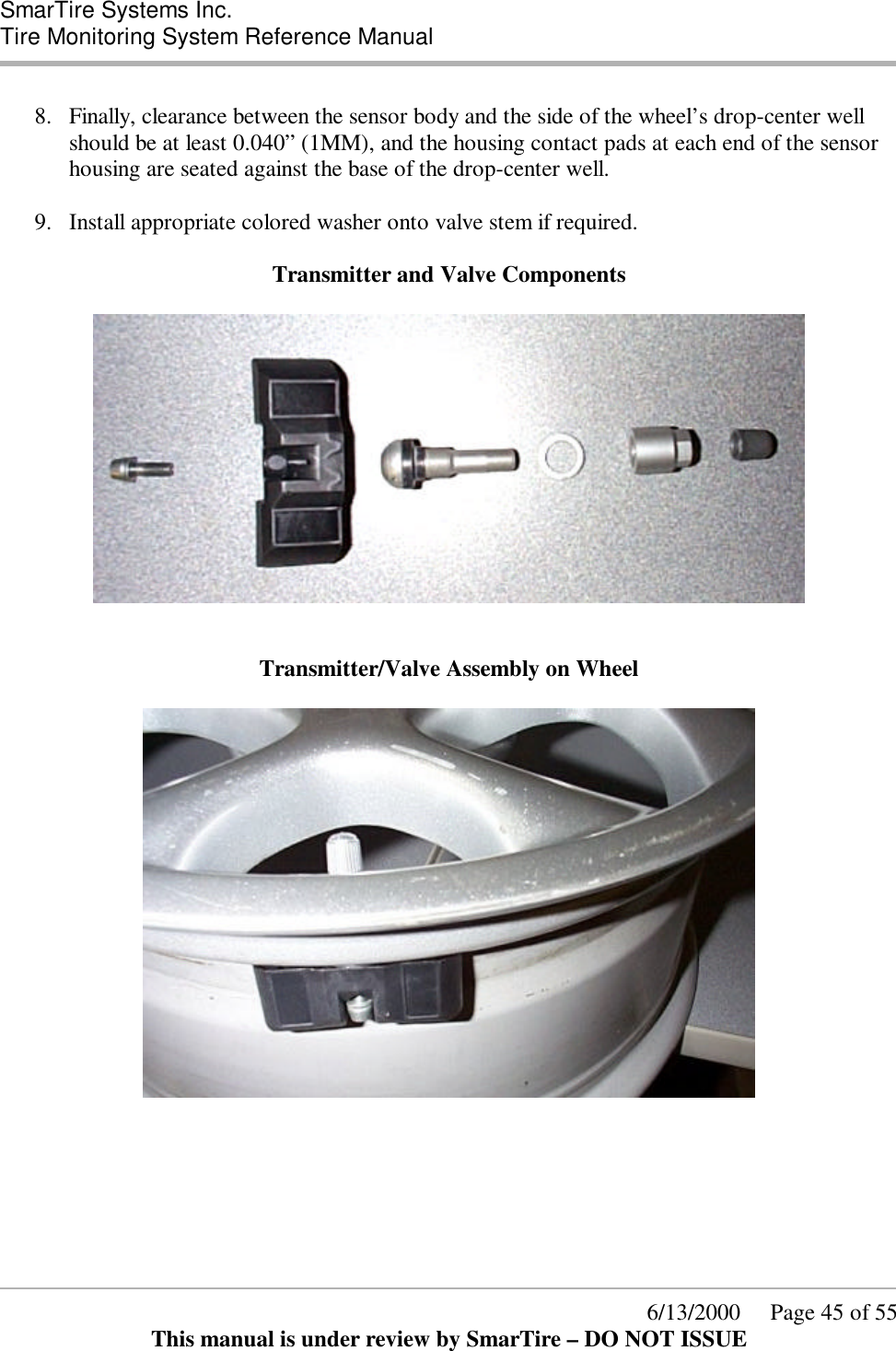
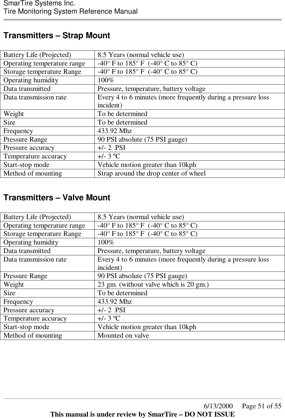
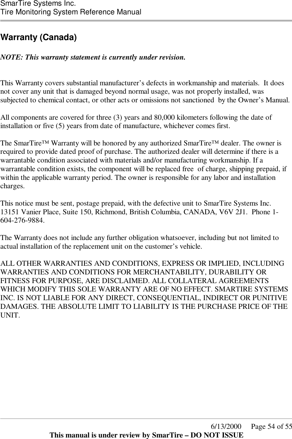
![SmarTire Systems Inc. Tire Monitoring System Reference Manual 6/13/2000 Page 42 of 55 This manual is under review by SmarTire – DO NOT ISSUE Installation Valve Mount Transmitter Procedure Overview 1. Deflate and demount the tire. 2. Verify that the wheel can accept a valve mount transmitter 3. Install the transmitter. 4. Mount the tire and inflate to the proper pressure. Alligator Valve Selection Process and Verification of Proper Assembly Fit Internal Visual Inspection of the Wheel or Rim 1. Confirm location of drop-center: • Is it nearer to front or back side of the wheel? – • If near front, use the strap mount sensor. • If near back, continue. 2. Confirm location of the valve: • Is it beside the drop-center well, but at no more than a 10-degree angle? – • If more than 10-degrees, use the strap mount sensor. • If close, then continue. 3. Confirm diameter of valve hole in the wheel: • Is it 0.453” (11.6MM)? • [The only next closest standard sizes are 0.327” (8.38MM) and 0.625” (16.03MM)] – • If smaller/larger, use the strap mount sensor. • If confirmed 0.453” (11.6MM) diameter, then continue. 4. Confirm available clearance for the valve attachment nut: • Is there 0.625” (16MM) diameter? • [This clearance is adequate in most cases, but there are some wheels in the market where we have found the anchor nut and washer to be 0.060” (1.5MM) too large.] – • If less, then use the strap mount sensor. • If more, then continue.](https://usermanual.wiki/Bendix-Commercial-Vehicle-Systems/RX433R-2/User-Guide-165177-Page-42.png)
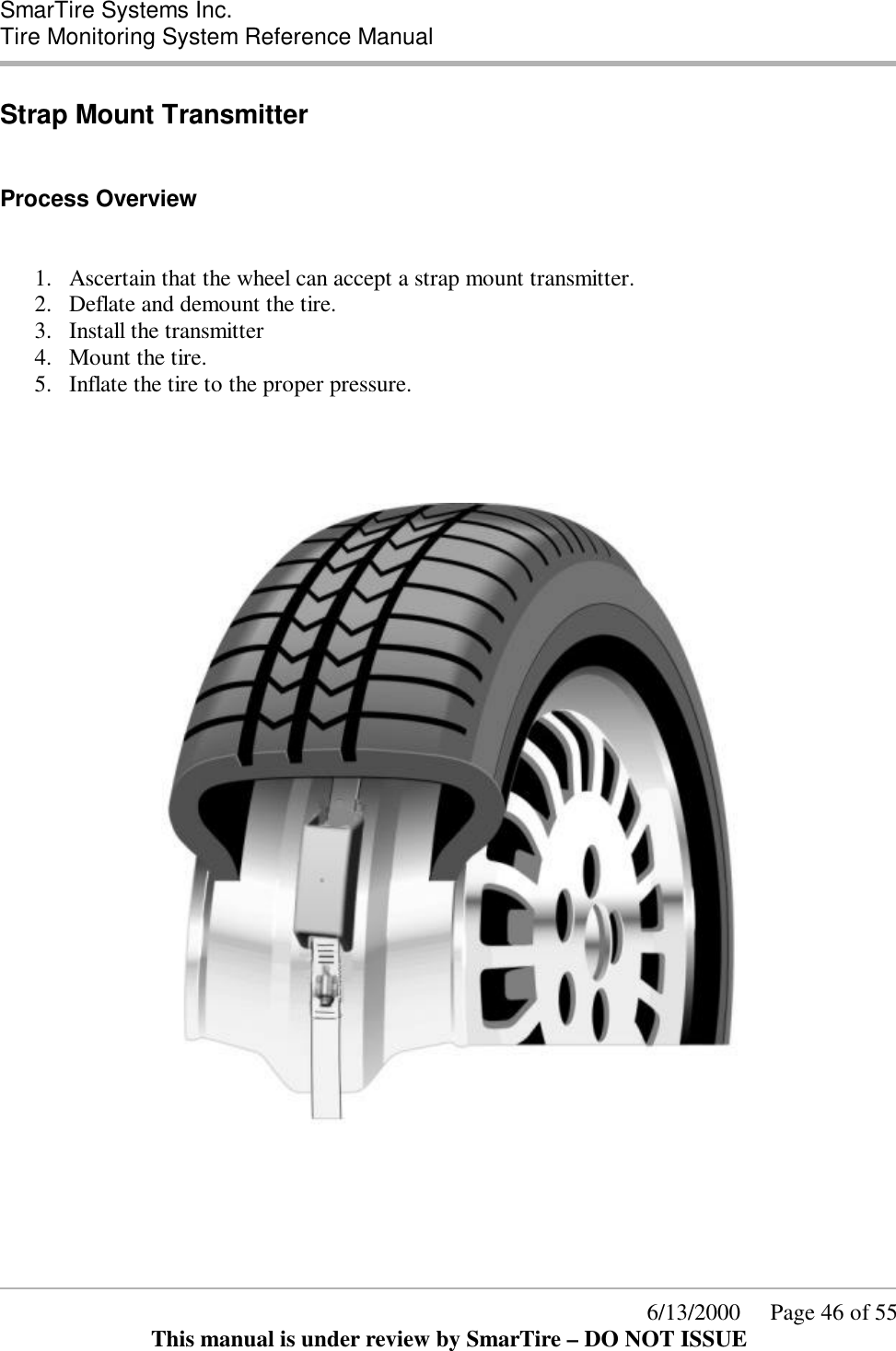
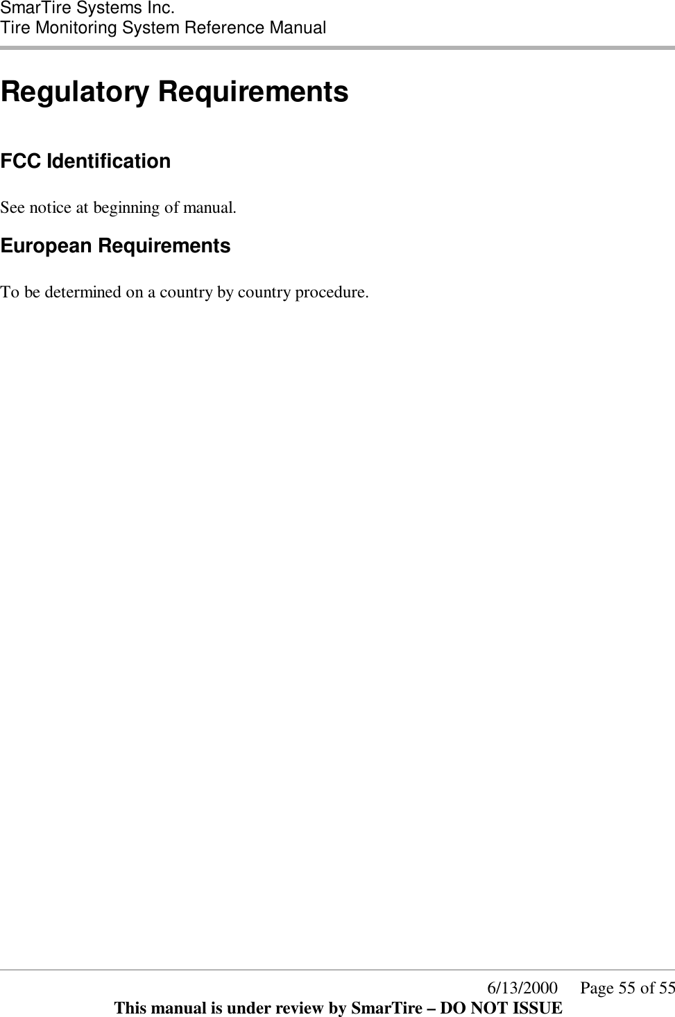
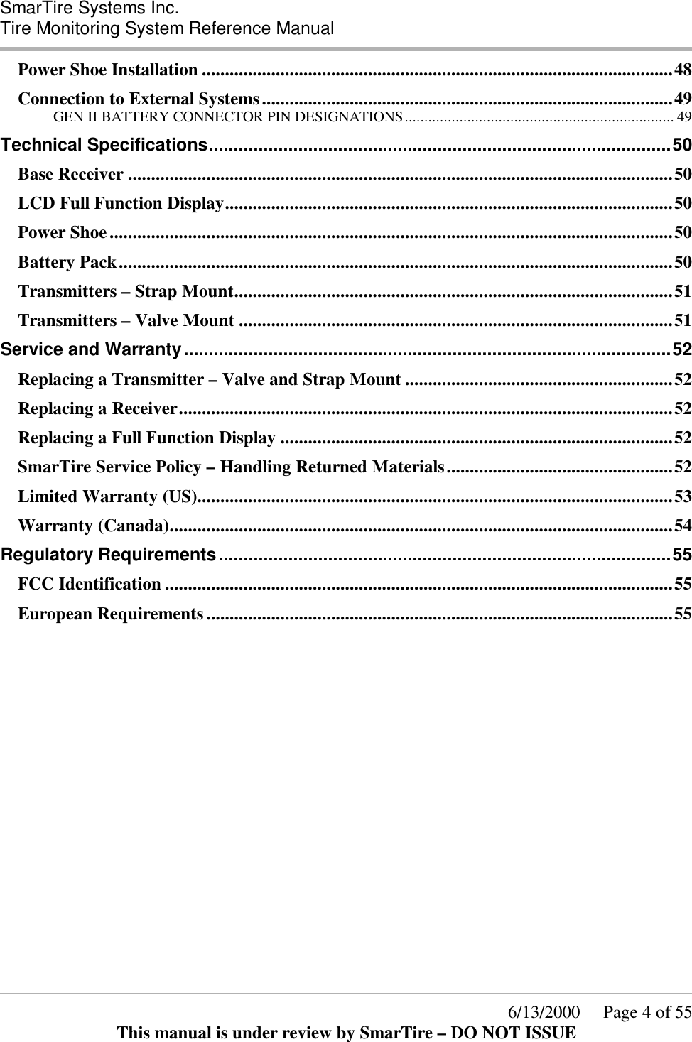
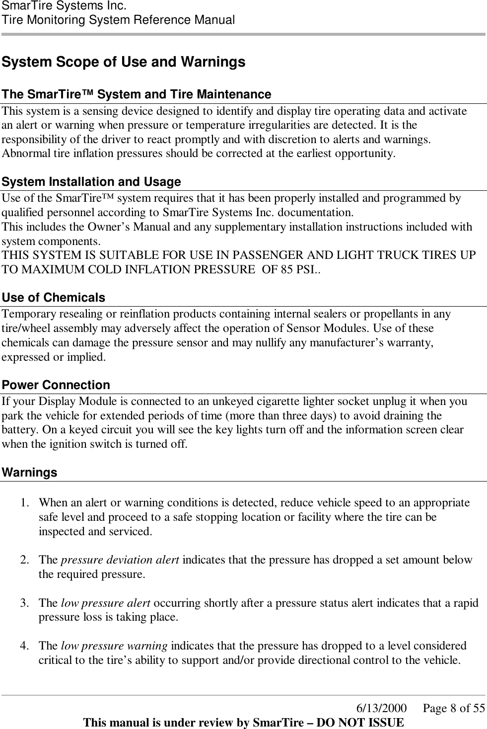
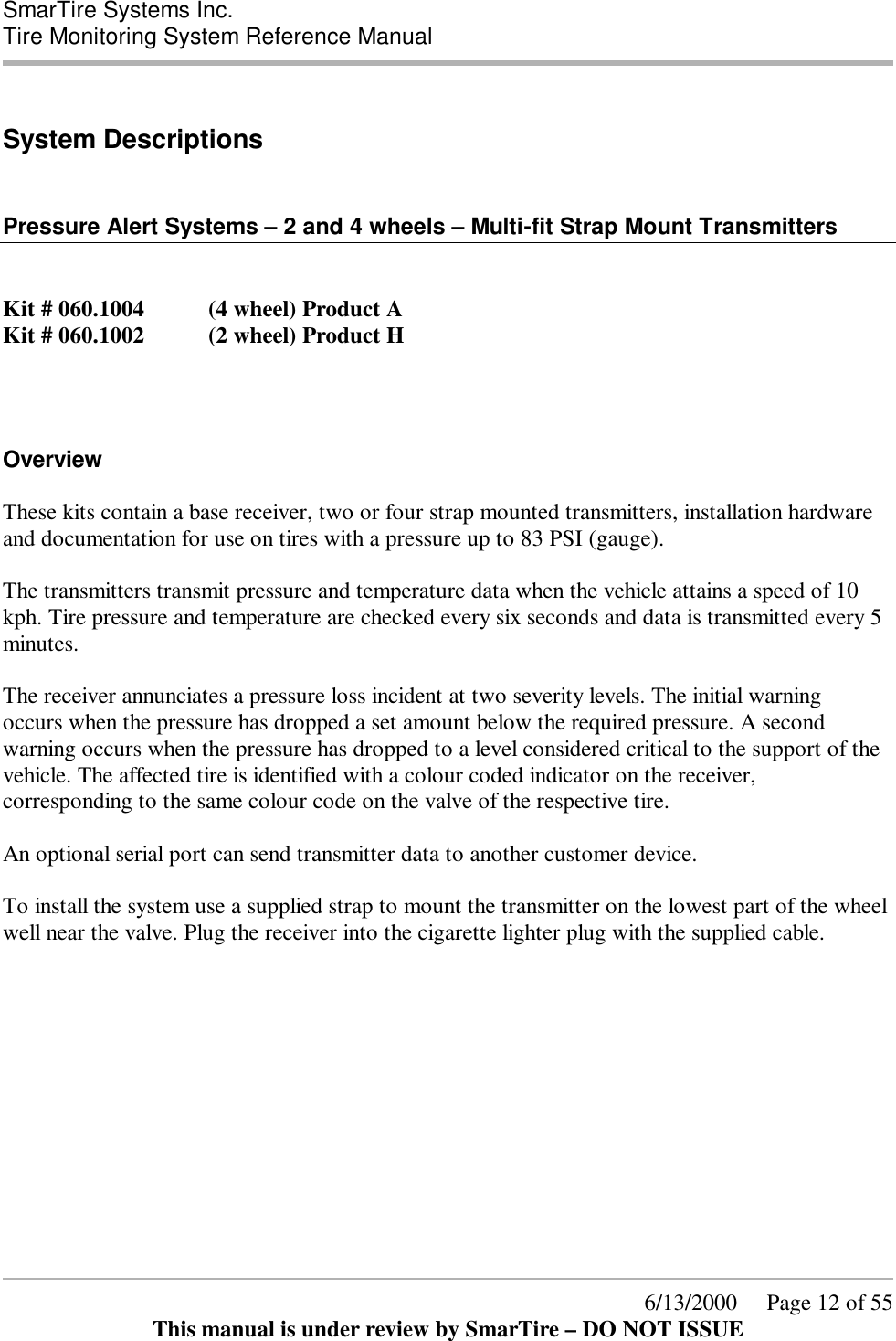
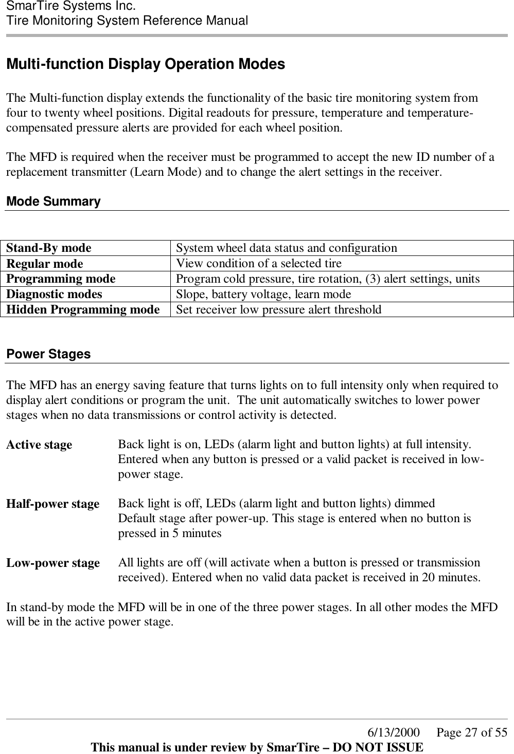
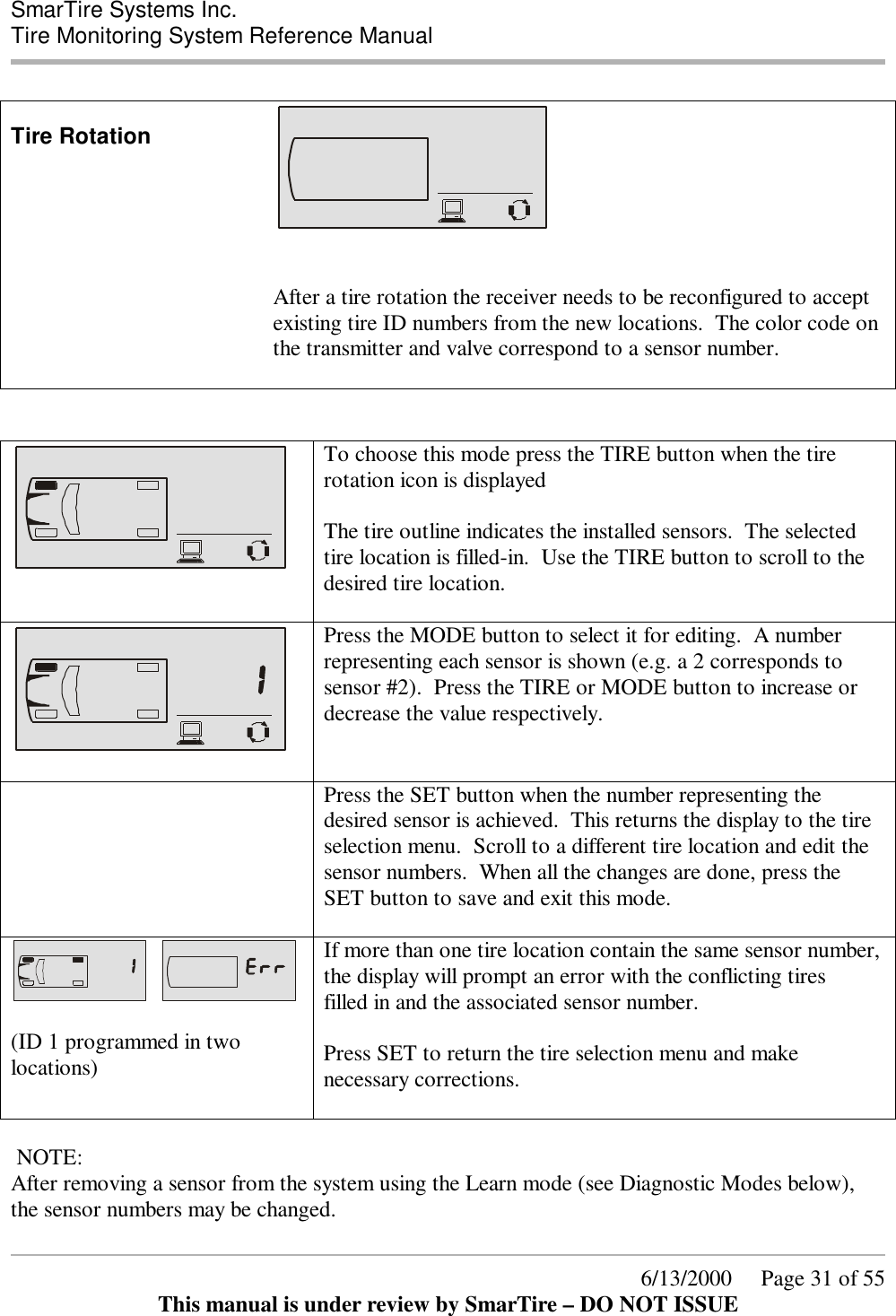
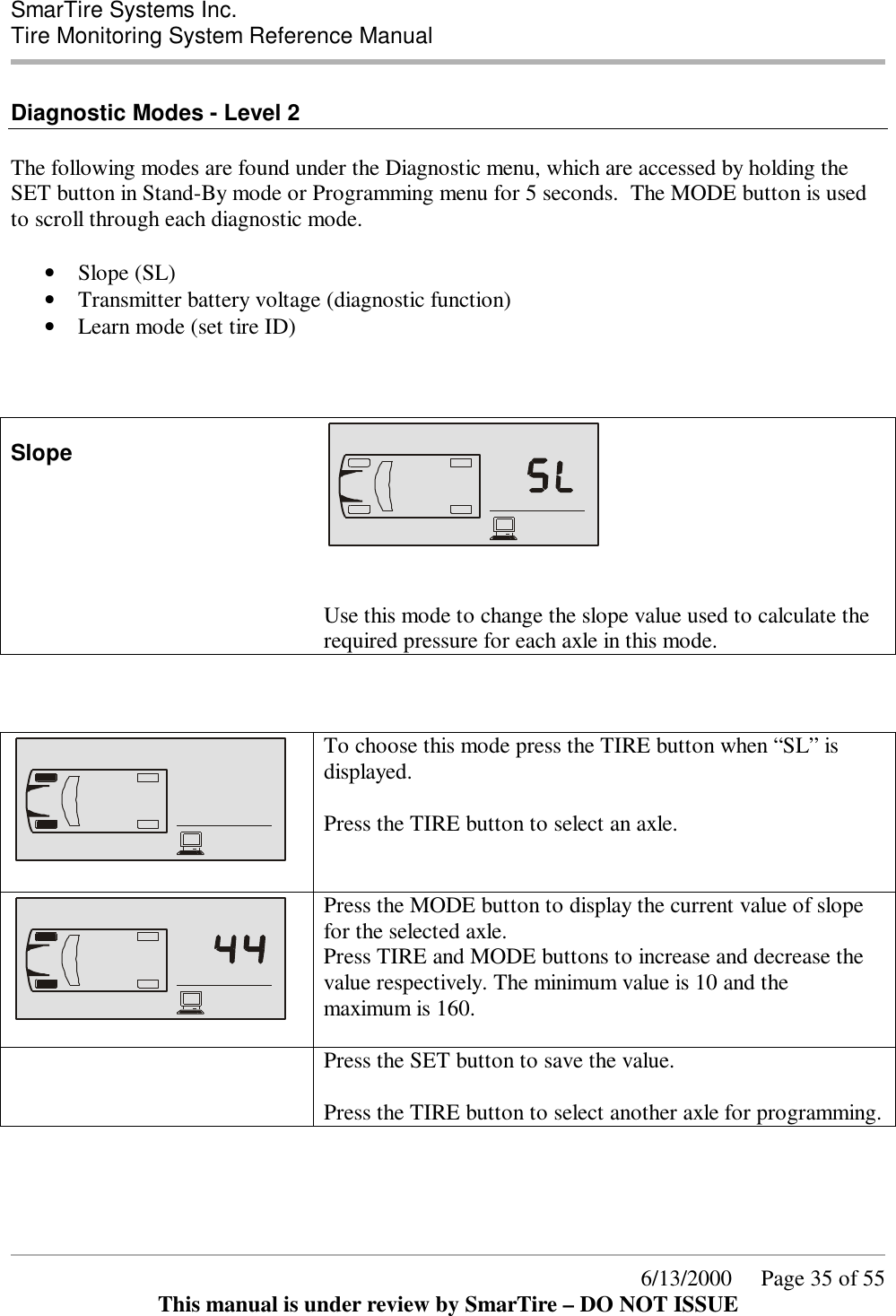
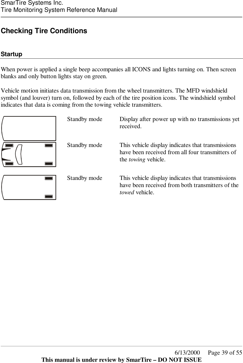
![SmarTire Systems Inc. Tire Monitoring System Reference Manual 6/13/2000 Page 43 of 55 This manual is under review by SmarTire – DO NOT ISSUE 5. Confirm maximum rim thickness at valve clamping area: • Is it 0.156” (4MM)? • [Normally not a problem with a 0.453” diameter valve hole] – • If greater, then use the strap mount sensor. • If less, then continue. 6. Confirm depth of the drop-center well near the valve hole: • Is it 0.67” (17.3MM) below the humps of the bead seats? • If shallower/deeper, then consider using the strap mount sensor. • If OK, then continue. 7. Confirm width of the flat base of the drop-center well: • Is it at least 0.85” (22MM)? • If less, then installation of either the valve or strap mount sensor may not be possible. • If OK, then continue. 8. Confirm relative position of the valve grommet-sealing surface of the valve hole of the adjacent side or top edge of the drop-center well: • Is valve hole recessed 0.25” (6MM)? • If recessed considerably more, then use the strap mount sensor. • If essentially flush or less, then continue. 0.453"0.156"Transmitter contact padsTransmitter attachment screwValve anchor nutValve holeMinimum drop centre width =.85”10 degreesRim thicknessWasherRimMinumumdrop-centredepth = .67”Wall angle Alligator Valve Selection and Fit Verification](https://usermanual.wiki/Bendix-Commercial-Vehicle-Systems/RX433R-2/User-Guide-165177-Page-43.png)
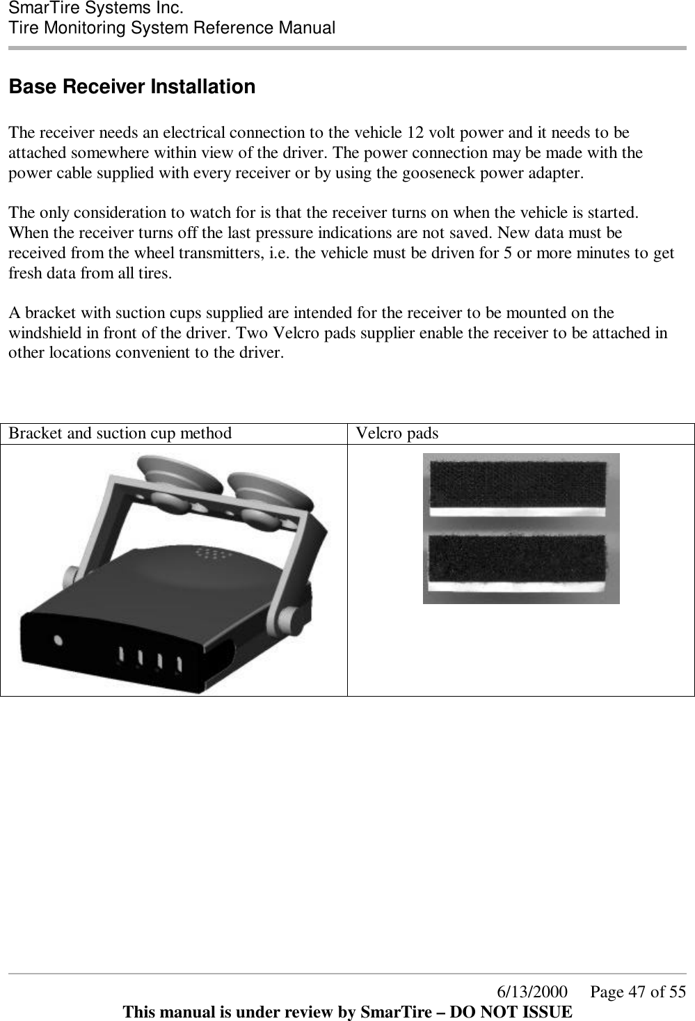
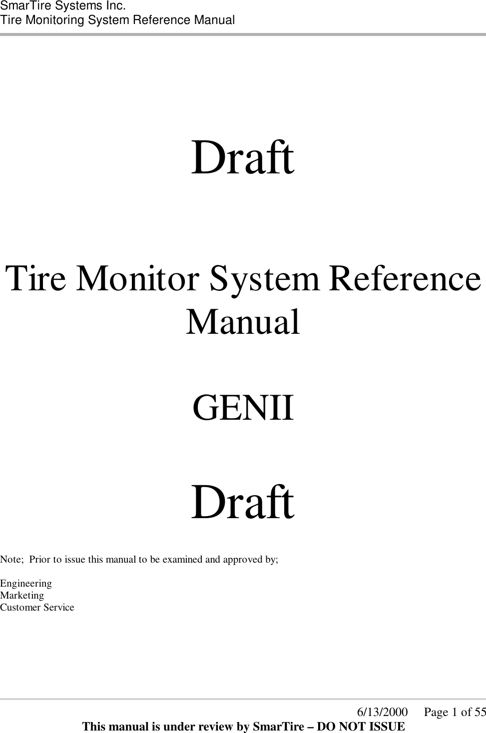
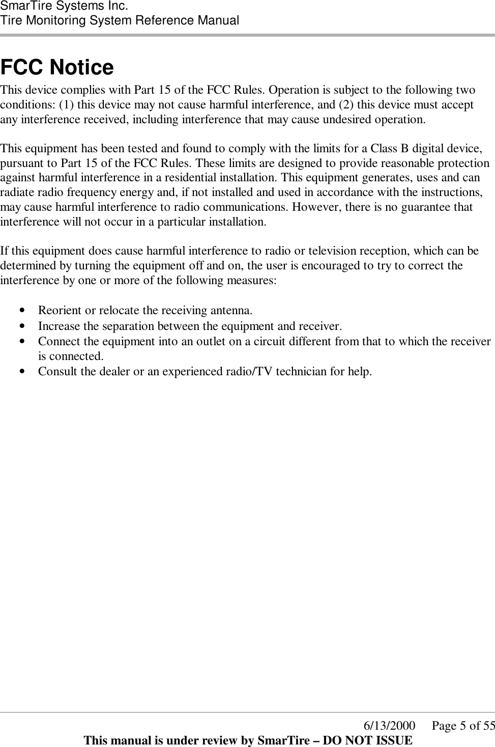
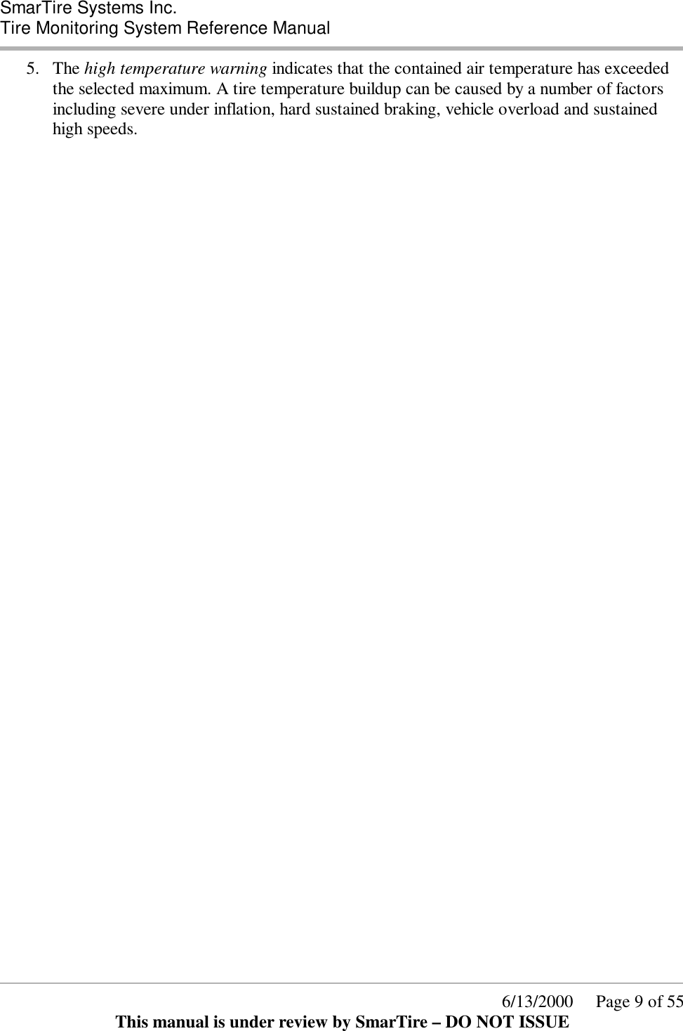
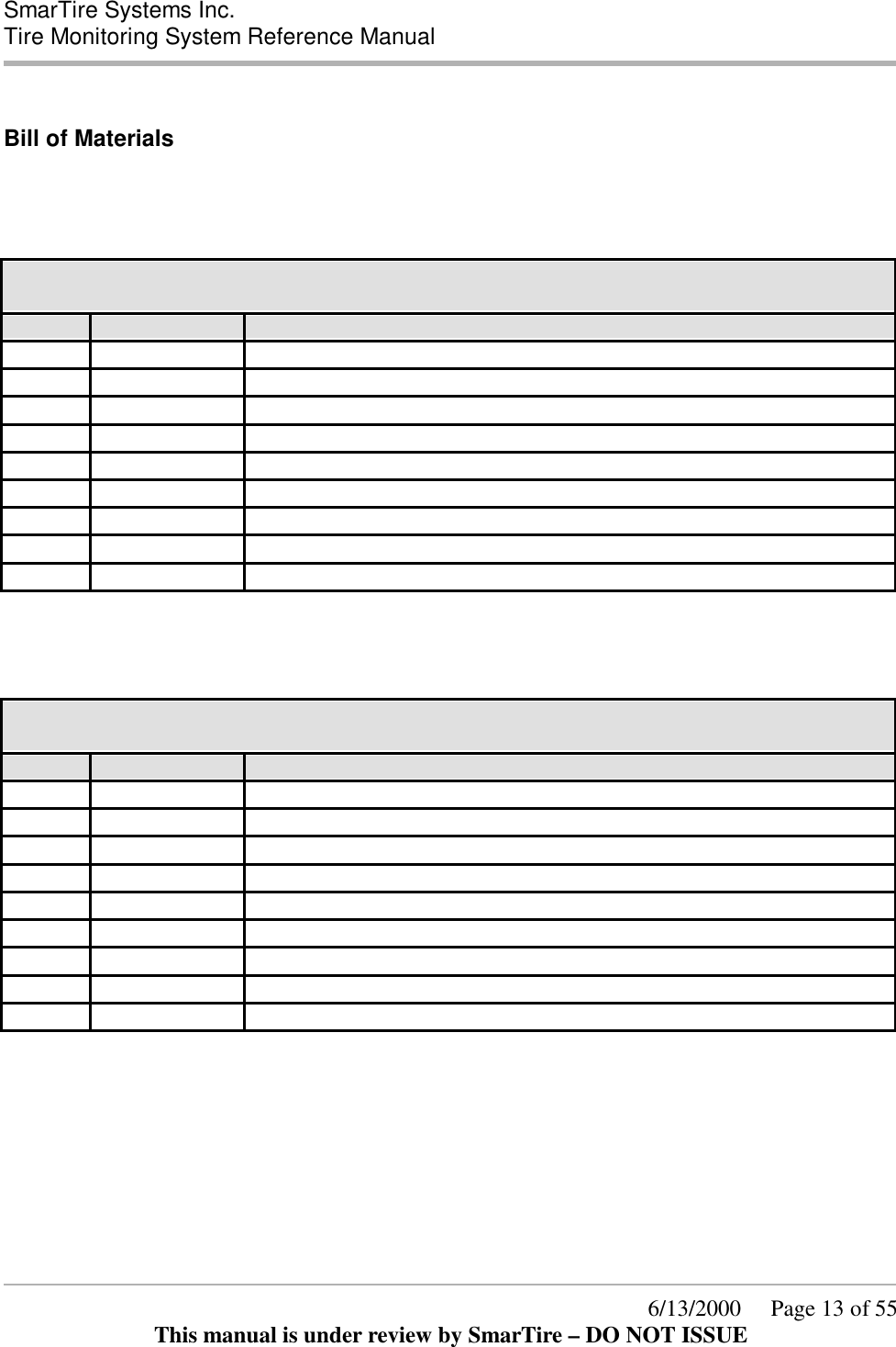
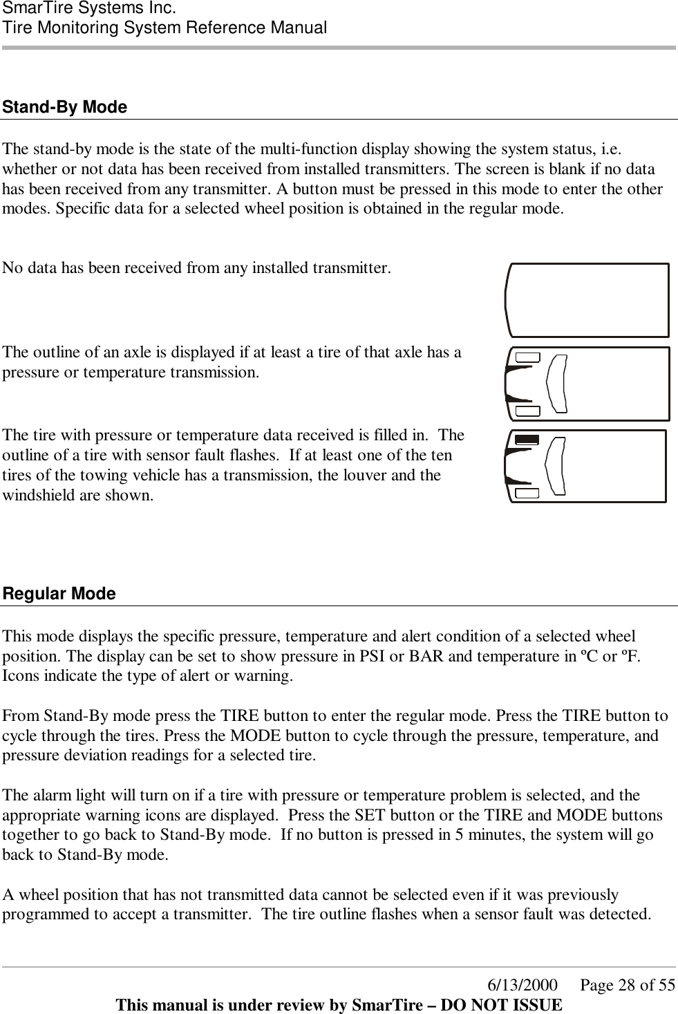
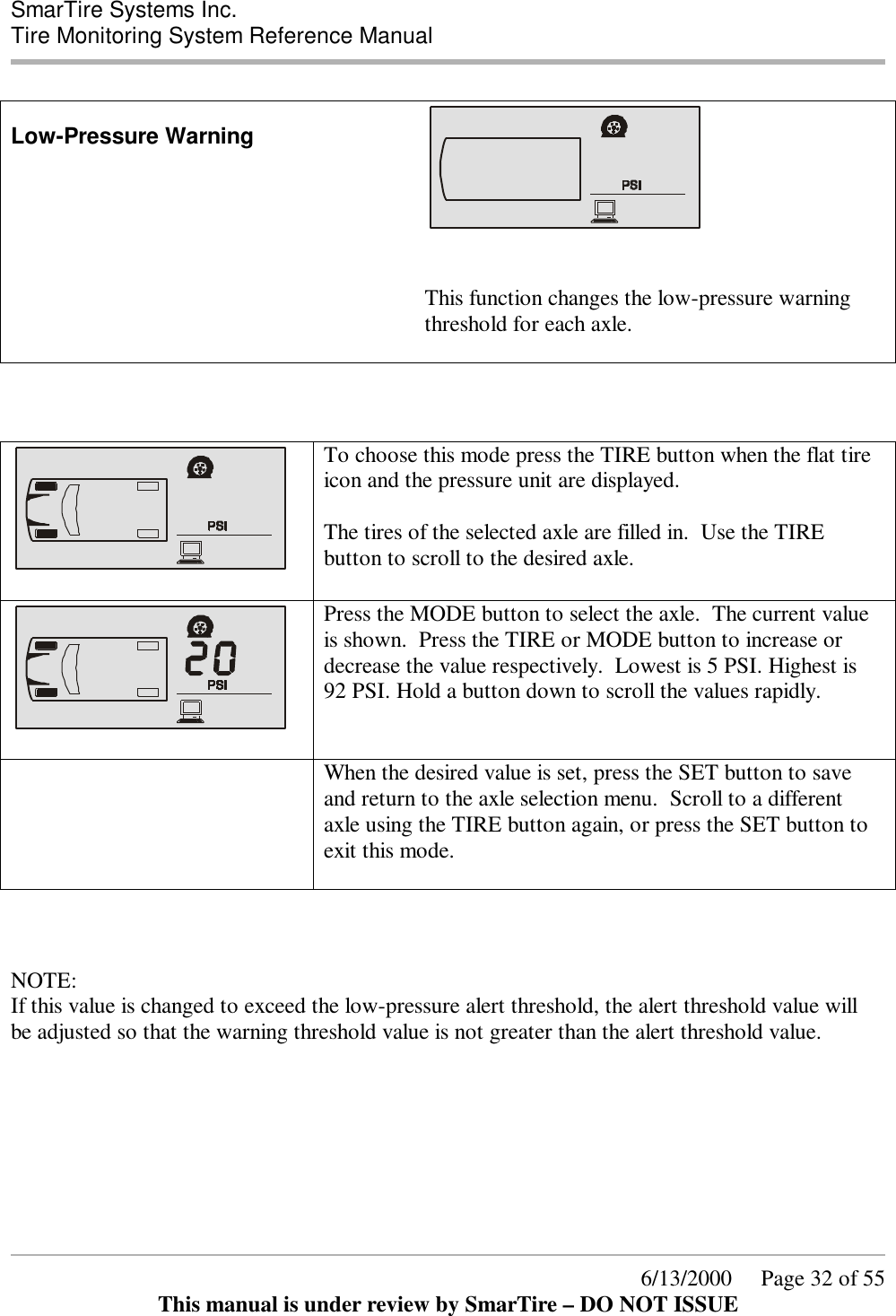
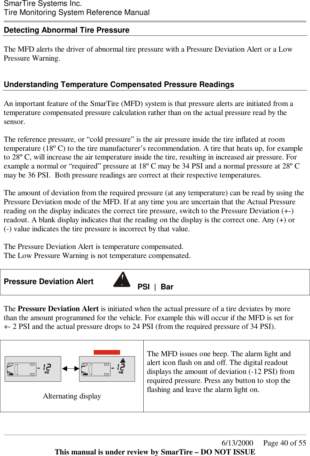
![SmarTire Systems Inc. Tire Monitoring System Reference Manual 6/13/2000 Page 44 of 55 This manual is under review by SmarTire – DO NOT ISSUE 1. Start by using the valve assembly with longest of the three bases (Alligator #59.0054) 2. Remove the sensor attachment screw and install the valve body (into valve hole from the front side), washer and nut. Finger-tighten the nut until grommet is evenly seated. Make sure the fit of the valve body/grommet and the clearance of the washer/nut with respect to wheel. 3. Place the sensor’s spherical mounting surface against the matching surface of the valve. Pivot the sensor housing toward the bottom of the drop-center well until both contact pads rest on the wheel. Confirm that the sensor’s only contact with the wheel is at the two contact pads. Note the clearance between the sensor housing and the side of the drop-center well, including the bottom radius. This space should be approximately 0.080” (2MM). • If clearance is greater than 0.25” (6MM), consider using a valve with a shorter base. • If the clearance is between 0.25” and 0.44” (6.7MM and 11.3MM), switch to the valve assembly with the next shorter base (Alligator #59.0044). • If the clearance is greater than 0.44” (11.3MM), then utilize the valve assembly with the shortest base (Alligator #59.0034). • If no additional valve selections are available, then use the strap mount sensor. 4. Repeat the above procedure to verify housing clearance at both the top and bottom of the drop-center well. 5. Check the position of the valve attachment hole in the base of the valve body relative to the housing adjustment slot: • Is hole completely visible with the housing firmly seated against both the wheel and valve? • If the hole is not completely visible, then use the strap mount sensor. • If the hole is completely visible with some adjustment remaining, then continue. 6. Tighten valve anchor nut to a torque value of 36 in.-lb. (4+/-0.05Nm). • [Note: It is very important to tighten the valve anchor nut to the defined torque value prior to tightening the sensor attachment] 7. Assemble sensor housing and attachment screw onto the base of the valve. Before tightening, hold sensor housing snugly against both the valve and the bottom of the wheel’s drop-center well. Tighten the sensor attachment screw to a torque of 36 in.-lb. (4+/-0.05Nm). Visually confirm that clearance remains between the top and bottom corners of the sensor housing and the wheel surface.](https://usermanual.wiki/Bendix-Commercial-Vehicle-Systems/RX433R-2/User-Guide-165177-Page-44.png)