Bendix Commercial Vehicle Systems TX433CS-3 Tire Monitoring Sensor User Manual
Bendix Commercial Vehicle Systems LLC Tire Monitoring Sensor
User Manual

Dealer Stamp
SmarTire Systems Inc. SmarTire Europe Limited
Suite 150, 13151 Vanier Place Park 34
Richmond, British Columbia Didcot, Oxfordshire
Canada, V6V 2J1 United Kingdom, OX11 7WB
Tel: 1.604.276.9884 Tel: +44.1235.511010
Fax: 1.604.276.0864 Fax: +44.1235.514640
Email: info@smartire.com Email: info@smartire.co.uk
www.smartire.com www.smartire.com
SMARTIRE HIGH PRESSURE TIRE MONITORING SYSTEM
INSTALLATION INSTRUCTIONS 710.0016 13-Mar-04
Parts
QTY Part
number Description QTY Part
number Description
1 200.0087 Receiver, Shielded 1 101.1060 Antenna Kit, 60’
1 200.0068 Full Function Display (FFD) 1 101.1040 Antenna Kit, 40’
4 200.0101 Transmitter - Strap Ts-2 1 101.1020 Antenna Kit, 20’
4 264.0115 Strap - Stainless Steel Clamp
1 260.0157 FFD Cable
1 260.0158 Power Cable Note: Antennas
purchased as required
Technical Specifications
Receiver Transmitter
Input Supply 10 -18 vDC
Power Consumption Normal = 480 mW, Max = 1.90 W
Weight 454 g, (16.0 oz) 40 g (1.4 oz)
Dimensions 102 x 117 x 38 mm (4.0 x 4.6 x 1.5 in.) 71 x 33 x 16 mm (2.8 x 1.3 x .63 in.)
Operating Temperature -40 ºC to 85 ºC (-40 ºF x 185 ºF) -40 ºC to 125 ºC (-40 ºF x 257 ºF)
Pressure Accuracy +/- 4.35 PSI (0.3 BAR)
Maximum Cold Inflation
Pressure
160 PSI (11.03 Bar)
Maximum Operating
Pressure 188 PSI (13.0 Bar)
Battery Life 5 years at 48,000 km/yr (30,000
miles/yr) - approx.
Factory Default Pressure Settings
The default pressure settings can be customized to suit the application as required. Use the Full
Function Display and follow the SmarTire FFD Manual carefully to change the default settings if
required.
Cold Inflation Pressure 125 PSI
Low Pressure Warning 110 PSI
Pressure Deviation Alert 10 PSI
High Temperature Warning 195º F
Warnings
This tire monitoring system does not in any way replace the need for regular maintenance of the tire
pressures and tire conditions.
System Installation and Usage
Use of the SmarTire® system requires that it has been properly installed and programmed by qualified
personnel according to SmarTire Systems Inc. documentation. This includes the Owner’s Manual and
any supplementary installation instructions included with system components.
Use of Chemicals
Temporary resealing or reinflation products containing internal sealers or propellants in any tire/wheel
assembly may adversely affect the operation of the Sensor/Transmitters.
Reacting to Alerts
When an alert or warning condition is detected, reduce vehicle speed to an appropriate safe level and
proceed to a safe stopping location or facility where the tire can be inspected and serviced. The low
pressure alert or warning indicates that the air pressure has dropped to a selected minimum.
FCC NOTICE
This device complies with Part 15 of the FCC Rules. Operation is subject to thefollowing two conditions: (1) this
device may not cause harmful interference, and(2) this device must accept any interference received, including
interference thatmay cause undesired operation.This equipment has been tested and found to comply with the
limits for a Class Bdigital device, pursuant to Part 15 of the FCC Rules. These limits are designed toprovide
reasonable protection against harmful interference in a residentialinstallation. This equipment generates, uses and
can radiate radio frequency energyand, if not installed and used in accordance with the instructions, may cause
harmfulinterference to radio communications. However, there is no guarantee thatinterference will not occur in a
particular installation.If this equipment does cause harmful interference to radio or television reception,which can
be determined by turning the equipment off and on, the user isencouraged to try to correct the interference by one
or more of the followingmeasures:•Reorient or relocate the receiving antenna.•Increase the separation between
the equipment and receiver.•Connect the equipment into an outlet on a circuit different from that to whichthe
receiver is connected.•Consult the dealer or an experienced radio/TV technician for help.Changes or modifications
to this device without the express approval of SmarTireSystems Inc. may void the user’s authority to use this
device.
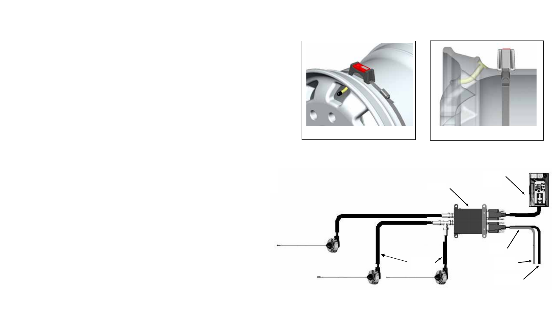
Installation of Transmitters
1. Slide the stainless steel straps through each of the Transmitters.
2. Dismount tire from wheel.
3. Position strap/Transmitter assembly around wheel at the lowest point of the drop-center. See Figures 1 and 2.
4. The strap transmitter is to be positioned 3” from the worm gear
5. Position the Transmitter at the valve stem opening then pull strap tight. Push in on the worm gear nut to hold
the position.
6. Tighten with 5/16” nut driver or screwdriver until Transmitter is secure (35” pounds torque).
7. Cut excess strap leaving 1” past the worm gear.
8. Mount tire being careful not to pinch the Transmitter with the bead of the tire.
9. Balance the tire.
10. Mount the tire on the vehicle.
Testing the System
1. Turn on the ignition switch and verify that the Receiver beeps three times and the FFD turns on.
2. Reduce the air in a tire to 3 PSI below the alert level (15 PSI or 1.03 BAR), and verify that the warning
light of the FFD turns on.
3. Re-inflate the tire.
4. Repeat steps 2 and 3 for remaining tire positions.
5. In cases where the settings are not appropriate to the installation, use the FFD manual to program the
system to the desired settings.
Figure 5 – System wiring
Red to
positive
Black to
ground
Optional
antennas
Receiver
Full
Function
Display
Power
Cable
Installation of Receiver and Full Function Display
1. Install the antenna according to instructions in the antenna kit.
2. Find a suitable location for the Receiver and Full Function Display assembly. The Receiver is normally
installed behind the dashboard. The Full Function Display is assembled somewhere on or in the dashboard.
3. Wire the system as shown in Figure 5. Plug the Full Function Display into the left plug of the Receiver. Plug
the power cable into right side plug.
4. The red wire of the power cable connects to a positive fused connection. The black wire connects to
ground.
Note: All connections must be made with the vehicle batter
y
isolated
Figure 2 – Transmitter side View
Figure 1 – Wheel Installation