Bendix Commercial Vehicle Systems TX433TS-2 Wireless Tire Monitoring System User Manual GENII usermanual
Bendix Commercial Vehicle Systems LLC Wireless Tire Monitoring System GENII usermanual
EXHIBIT 8 USER MANUAL

SmarTire Systems Inc.
Tire Monitoring System Reference Manual
6/13/2000 Page 1 of 55
This manual is under review by SmarTire – DO NOT ISSUE
Draft
Tire Monitor System Reference
Manual
GENII
Draft
Note; Prior to issue this manual to be examined and approved by;
Engineering
Marketing
Customer Service

SmarTire Systems Inc.
Tire Monitoring System Reference Manual
6/13/2000 Page 2 of 55
This manual is under review by SmarTire – DO NOT ISSUE
Table of Contents
FCC Notice.....................................................................................................................5
Introduction....................................................................................................................6
Purpose of Manual................................................................................................................6
About Tire Monitoring Systems ...........................................................................................6
Feature Summary.......................................................................................................................................... 7
System Scope of Use and Warnings......................................................................................8
The SmarTire™ System and Tire Maintenance.............................................................................................. 8
System Installation and Usage....................................................................................................................... 8
Use of Chemicals.......................................................................................................................................... 8
Power Connection......................................................................................................................................... 8
Warnings ...................................................................................................................................................... 8
SmarTire Product Overview........................................................................................10
Product List.........................................................................................................................10
Tire Monitor System Kit Component Table......................................................................11
System Descriptions ............................................................................................................12
Pressure Alert Systems – 2 and 4 wheels – Multi-fit Strap Mount Transmitters............................................. 12
Overview................................................................................................................................................ 12
Bill of Materials ..................................................................................................................................... 13
Component Images................................................................................................................................. 14
Pressure Alert Systems – 2 and 4 wheels – Multi-fit Valve Mount Transmitters............................................ 15
Overview................................................................................................................................................ 15
Bill of Materials ..................................................................................................................................... 16
Component Images................................................................................................................................. 17
Pressure Alert Full Function Display ........................................................................................................... 18
Overview................................................................................................................................................ 18
Bill of Materials ..................................................................................................................................... 19
Component Images................................................................................................................................. 19
Pressure Alert Flexible Power Adaptor........................................................................................................ 20
Overview................................................................................................................................................ 20
Bill of Materials ..................................................................................................................................... 20
Component Image .................................................................................................................................. 20
Pressure Alert Transmitter Kit – 2 - Multi-fit Strap Mount Transmitters....................................................... 21
Overview................................................................................................................................................ 21
Bill of Materials ..................................................................................................................................... 21
Component Image .................................................................................................................................. 21
Pressure Alert Transmitter Kit – 2 - Multi-fit Valve Mount Transmitters...................................................... 22
Overview................................................................................................................................................ 22
Bill of Materials ..................................................................................................................................... 22
Component Image .................................................................................................................................. 22
Pressure Alert Valve Kits............................................................................................................................ 23
Overview................................................................................................................................................ 23
Component Image .................................................................................................................................. 23
Receiver........................................................................................................................24

SmarTire Systems Inc.
Tire Monitoring System Reference Manual
6/13/2000 Page 3 of 55
This manual is under review by SmarTire – DO NOT ISSUE
Operation.............................................................................................................................24
Programming the Receiver.................................................................................................24
Multi-function Display (MFD)......................................................................................25
Controls and Display...........................................................................................................25
ICON Summary Table........................................................................................................26
Multi-function Display Operation Modes..........................................................................27
Mode Summary .......................................................................................................................................... 27
Stand-By mode ........................................................................................................................................... 27
Power Stages .............................................................................................................................................. 27
Stand-By Mode........................................................................................................................................... 28
Regular Mode ............................................................................................................................................. 28
Programming Modes ..........................................................................................................29
Standard Operating Settings – Level 1......................................................................................................... 29
Cold Inflation Pressure ........................................................................................................................... 30
Tire Rotation.......................................................................................................................................... 31
Low-Pressure Warning........................................................................................................................... 32
Pressure Deviation Alert......................................................................................................................... 33
High Temperature Alert.......................................................................................................................... 34
Units ...................................................................................................................................................... 34
Diagnostic Modes - Level 2......................................................................................................................... 35
Slope...................................................................................................................................................... 35
Battery Condition................................................................................................................................... 36
Learn...................................................................................................................................................... 37
Hidden Programming Mode – Level 3......................................................................................................... 38
Low Pressure Alert................................................................................................................................. 38
Checking Tire Conditions...................................................................................................39
Startup........................................................................................................................................................ 39
Detecting Abnormal Tire Pressure............................................................................................................... 40
Understanding Temperature Compensated Pressure Readings...................................................................... 40
Pressure Deviation Alert......................................................................................................................... 40
Low Pressure Warning............................................................................................................................ 41
Detecting Excessive Tire Air Temperature................................................................................................... 41
High Temperature Warning .................................................................................................................... 41
Installation....................................................................................................................42
Valve Mount Transmitter...................................................................................................42
Procedure Overview.................................................................................................................................... 42
Alligator Valve Selection Process and Verification of Proper Assembly Fit.................................................. 42
Internal Visual Inspection of the Wheel or Rim....................................................................................... 42
Alligator Valve Selection and Fit Verification......................................................................................... 43
Strap Mount Transmitter...................................................................................................46
Process Overview................................................................................................................................... 46
Base Receiver Installation...................................................................................................47
LCD unit Installation..........................................................................................................48
LCD unit Installation..........................................................................................................48

SmarTire Systems Inc.
Tire Monitoring System Reference Manual
6/13/2000 Page 4 of 55
This manual is under review by SmarTire – DO NOT ISSUE
Power Shoe Installation ......................................................................................................48
Connection to External Systems.........................................................................................49
GEN II BATTERY CONNECTOR PIN DESIGNATIONS..................................................................... 49
Technical Specifications.............................................................................................50
Base Receiver ......................................................................................................................50
LCD Full Function Display.................................................................................................50
Power Shoe..........................................................................................................................50
Battery Pack........................................................................................................................50
Transmitters – Strap Mount...............................................................................................51
Transmitters – Valve Mount ..............................................................................................51
Service and Warranty..................................................................................................52
Replacing a Transmitter – Valve and Strap Mount ..........................................................52
Replacing a Receiver...........................................................................................................52
Replacing a Full Function Display .....................................................................................52
SmarTire Service Policy – Handling Returned Materials.................................................52
Limited Warranty (US).......................................................................................................53
Warranty (Canada).............................................................................................................54
Regulatory Requirements...........................................................................................55
FCC Identification ..............................................................................................................55
European Requirements.....................................................................................................55

SmarTire Systems Inc.
Tire Monitoring System Reference Manual
6/13/2000 Page 5 of 55
This manual is under review by SmarTire – DO NOT ISSUE
FCC Notice
This device complies with Part 15 of the FCC Rules. Operation is subject to the following two
conditions: (1) this device may not cause harmful interference, and (2) this device must accept
any interference received, including interference that may cause undesired operation.
This equipment has been tested and found to comply with the limits for a Class B digital device,
pursuant to Part 15 of the FCC Rules. These limits are designed to provide reasonable protection
against harmful interference in a residential installation. This equipment generates, uses and can
radiate radio frequency energy and, if not installed and used in accordance with the instructions,
may cause harmful interference to radio communications. However, there is no guarantee that
interference will not occur in a particular installation.
If this equipment does cause harmful interference to radio or television reception, which can be
determined by turning the equipment off and on, the user is encouraged to try to correct the
interference by one or more of the following measures:
• Reorient or relocate the receiving antenna.
• Increase the separation between the equipment and receiver.
• Connect the equipment into an outlet on a circuit different from that to which the receiver
is connected.
• Consult the dealer or an experienced radio/TV technician for help.

SmarTire Systems Inc.
Tire Monitoring System Reference Manual
6/13/2000 Page 6 of 55
This manual is under review by SmarTire – DO NOT ISSUE
Introduction
Purpose of Manual
This manual is intended for use by service personnel and dealers. It contains detailed information
on operation, installation and service of the SmarTire Pressure Monitoring Systems (GEN-II).
About Tire Monitoring Systems
The SmarTire System consists of a receiver and optional programmable Multifunction Display,
which are conveniently mounted within easy view and reach of the driver. Wheel mounted
sensor/transmitters inside each tire measure contained air pressure and temperature and transmit
this data to the receiver. The receiver or Multifunction Display displays the location and/or value
of any detected abnormal tire pressure or temperature, alerting the driver at preset limits.
The Multifunction Display also provides convenient fingertip access to viewing the pressure,
temperature and pressure deviation of each tire.
SmarTire Systems Inc.
Tire Monitoring System Reference Manual
6/13/2000 Page 7 of 55
This manual is under review by SmarTire – DO NOT ISSUE
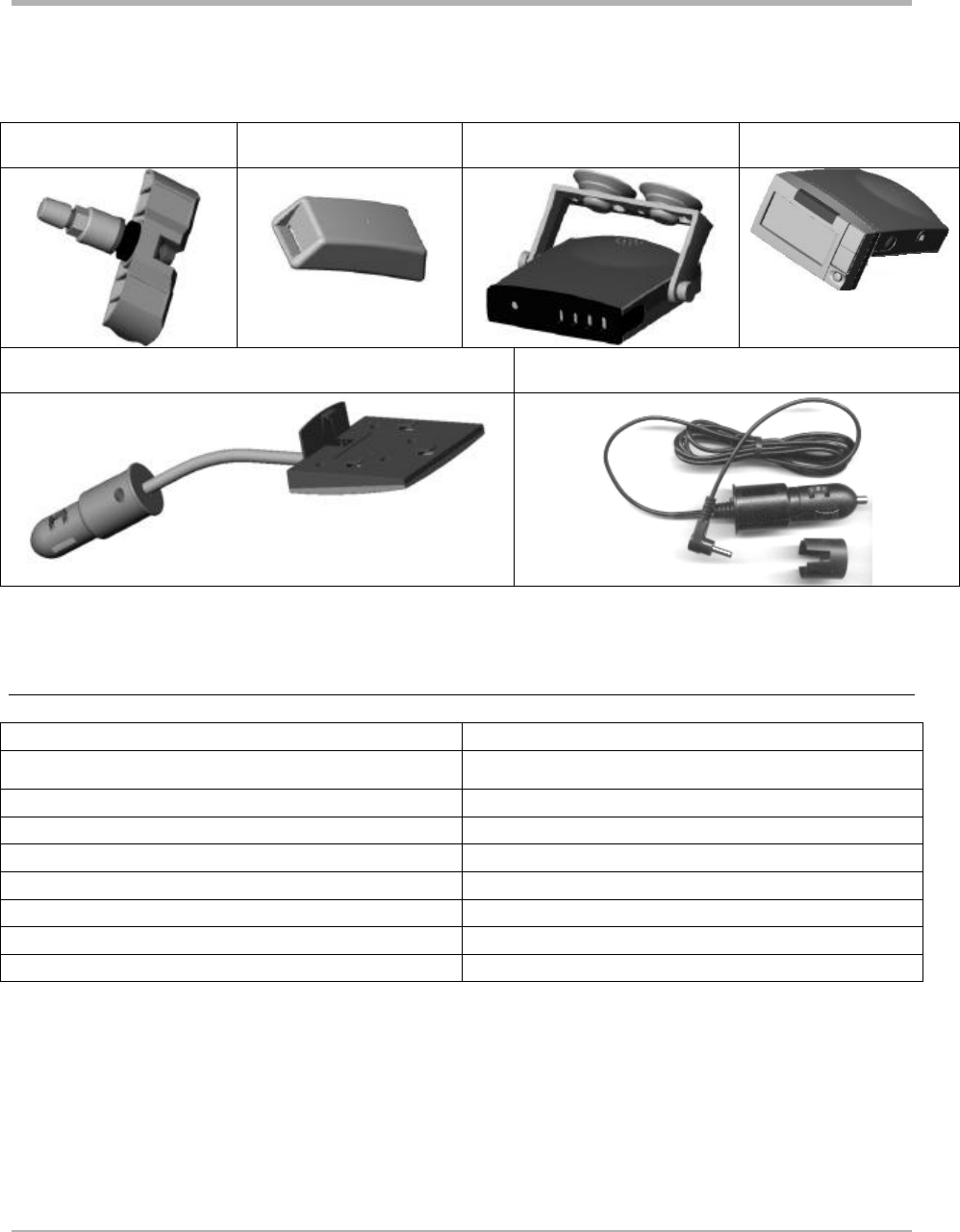
Tire Monitoring Components
Valve mount transmitter
Strap mount transmitter Receiver with mounting bracket Multi-function display
Power Adaptor (Gooseneck)
Receiver Power Cable
Feature Summary
Feature Function of
Low pressure alert Receiver
Low pressure warning Receiver and multi-function display
Pressure deviation alert Multi-function display
High temperature warning Multi-function display
Battery voltage Multi-function display
Temperature compensation factor (slope) Multi-function display
Transmitter ID learn mode Multi-function display

SmarTire Systems Inc.
Tire Monitoring System Reference Manual
6/13/2000 Page 8 of 55
This manual is under review by SmarTire – DO NOT ISSUE
System Scope of Use and Warnings
The SmarTire™ System and Tire Maintenance
This system is a sensing device designed to identify and display tire operating data and activate
an alert or warning when pressure or temperature irregularities are detected. It is the
responsibility of the driver to react promptly and with discretion to alerts and warnings.
Abnormal tire inflation pressures should be corrected at the earliest opportunity.
System Installation and Usage
Use of the SmarTire™ system requires that it has been properly installed and programmed by
qualified personnel according to SmarTire Systems Inc. documentation.
This includes the Owner’s Manual and any supplementary installation instructions included with
system components.
THIS SYSTEM IS SUITABLE FOR USE IN PASSENGER AND LIGHT TRUCK TIRES UP
TO MAXIMUM COLD INFLATION PRESSURE OF 85 PSI..
Use of Chemicals
Temporary resealing or reinflation products containing internal sealers or propellants in any
tire/wheel assembly may adversely affect the operation of Sensor Modules. Use of these
chemicals can damage the pressure sensor and may nullify any manufacturer’s warranty,
expressed or implied.
Power Connection
If your Display Module is connected to an unkeyed cigarette lighter socket unplug it when you
park the vehicle for extended periods of time (more than three days) to avoid draining the
battery. On a keyed circuit you will see the key lights turn off and the information screen clear
when the ignition switch is turned off.
Warnings
1. When an alert or warning conditions is detected, reduce vehicle speed to an appropriate
safe level and proceed to a safe stopping location or facility where the tire can be
inspected and serviced.
2. The pressure deviation alert indicates that the pressure has dropped a set amount below
the required pressure.
3. The low pressure alert occurring shortly after a pressure status alert indicates that a rapid
pressure loss is taking place.
4. The low pressure warning indicates that the pressure has dropped to a level considered
critical to the tire’s ability to support and/or provide directional control to the vehicle.

SmarTire Systems Inc.
Tire Monitoring System Reference Manual
6/13/2000 Page 9 of 55
This manual is under review by SmarTire – DO NOT ISSUE
5. The high temperature warning indicates that the contained air temperature has exceeded
the selected maximum. A tire temperature buildup can be caused by a number of factors
including severe under inflation, hard sustained braking, vehicle overload and sustained
high speeds.

SmarTire Systems Inc.
Tire Monitoring System Reference Manual
6/13/2000 Page 10 of 55
This manual is under review by SmarTire – DO NOT ISSUE
SmarTire Product Overview
The Tire Monitoring Systems are sold in several configurations and options. Below is a table
outlining the available kits, upgrades and spare components.
Product List
Product Product
Stock Code Description
A 060.1004 Pressure Alert System – 4 wheels – Multi fit Strap Mount Transmitters
H 060.1002 Pressure Alert System – 2 wheels – Multi fit Strap Mount Transmitters
B 060.2004 Pressure Alert System – 4 wheels - Valve Transmitters (valves not
included)
I 060.2002 Pressure Alert System – 2 wheels – Multi fit Valve Mount
Transmitters
D 061.4000 Pressure Alert Full Function Display (LCD-I)
E 061.4001 Pressure Alert Full Function Remote Display (LCD-R)
C 061.3000 Pressure Alert Flexible Power Adaptor
F 061.1002 Pressure Alert Transmitter Kit – 2 - Multi-fit Strap Mount
Transmitters
G 061.2002 Pressure Alert Transmitter Kit – 2 - Valve Transmitters (valves not
included)
063.2000 Pressure Alert 2 Valve Kit – A
063.2001 Pressure Alert 2 Valve Kit – B
063.2002 Pressure Alert 2 Valve Kit – C
063.2003 Pressure Alert 2 Valve Kit – D

SmarTire Systems Inc.
Tire Monitoring System Reference Manual
6/13/2000 Page 11 of 55
This manual is under review by SmarTire – DO NOT ISSUE
Tire Monitor System Kit Component Table
Kit Description Kit Components
Product Type Short Code
Base receiver
Receiver Cable Kit
Transmitter, Strap Mount
Transmitter, Valve Mount
LCD Multi
-function Display Type I
LCD Multi
-function Display Type R
Flexible Power Adaptor
Str
ap
Document Kit Basic
Document Kit , LCD
Installation Kit
Package Type A
Package Type B
Valve
- A
Valve
- B
Valve
- C
Valve
- C
Kit Stock
Code
Kit Description
200.0059
069.0002
200.0064
200.0065
200.0060
200.0068
200.0066
264.0115
700.0000
700.00
01
069.0001
276.0041
276.0042
A
060.1004 Pressure Alert System – 4
wheels – Multi fit Strap
Mount Transmitters
1
1
4
4
1
1
H
060.1002 Pressure Alert System – 2
wheels – Multi fit Strap
Mount Transmitters
1
1
2
2
1
1
B
060.2004 Pressure Alert System – 4
wheels - Valve Transmitters
(valves not incl.)
1
1
4
1
I 060.2002 Pressure Alert System – 2
wheels – Multi fit Valve
Mount Transmitters
1
1
2
1
D
061.4000 Pressure Alert Full Function
Display (LCD-I) 1
1
1
E
061.4001 Pressure Alert Full Function
Remote Display (LCD-R) 1
1
1
C
061.3000 Pressure Alert Flexible Power
Adaptor 1
1
F
061.1002 Pressure Alert Transmitter Kit
– 2 - Multi-fit Strap Mount
Transmitters
2
2
1
G
061.2002 Pressure Alert Transmitter Kit
– 2 - Valve Transmitters
(valves not included)
2
063.2000 Pressure Alert 2 Valve Kit –
A 2
063.2001 Pressure Alert 2 Valve Kit –
B 2
063.2002 Pressure Alert 2 Valve Kit –
C 2
063.2003 Pressure Alert 2 Valve Kit –
D 2

SmarTire Systems Inc.
Tire Monitoring System Reference Manual
6/13/2000 Page 12 of 55
This manual is under review by SmarTire – DO NOT ISSUE
System Descriptions
Pressure Alert Systems – 2 and 4 wheels – Multi-fit Strap Mount Transmitters
Kit # 060.1004 (4 wheel) Product A
Kit # 060.1002 (2 wheel) Product H
Overview
These kits contain a base receiver, two or four strap mounted transmitters, installation hardware
and documentation for use on tires with a pressure up to 83 PSI (gauge).
The transmitters transmit pressure and temperature data when the vehicle attains a speed of 10
kph. Tire pressure and temperature are checked every six seconds and data is transmitted every 5
minutes.
The receiver annunciates a pressure loss incident at two severity levels. The initial warning
occurs when the pressure has dropped a set amount below the required pressure. A second
warning occurs when the pressure has dropped to a level considered critical to the support of the
vehicle. The affected tire is identified with a colour coded indicator on the receiver,
corresponding to the same colour code on the valve of the respective tire.
An optional serial port can send transmitter data to another customer device.
To install the system use a supplied strap to mount the transmitter on the lowest part of the wheel
well near the valve. Plug the receiver into the cigarette lighter plug with the supplied cable.

SmarTire Systems Inc.
Tire Monitoring System Reference Manual
6/13/2000 Page 13 of 55
This manual is under review by SmarTire – DO NOT ISSUE
Bill of Materials
060.1004 Pressure Alert Systems – 4 wheels – Multi-fit Strap Mount Transmitters
QTY PER
STOCK CODE Description
1
069.0001 INSTALLATION KIT
1
069.0002 POWER CABLE KIT
1
200.0059 RECEIVER -BASE-GENII
4
200.0064 TRANSMITTER-STRAP-GENII
4
264.0115 STRAP - STAINLESS STEEL CLAMP
1
276.0041 BOX - PRODUCT KIT
1
276.0042 BOX - ELECTRONIC PARTS
1
276.0043 BAG TRANSMITTER SHIELD
1
700.0000 DOCUMENT KIT, GENII - BASIC
060.1002 Pressure Alert Systems – 2 wheels – Multi-fit Strap Mount Transmitters
QTY PER
STOCK CODE Description
1
069.0001 INSTALLATION KIT
1
069.0002 POWER CABLE KIT
1
200.0059 RECEIVER -BASE-GENII
2
200.0064 TRANSMITTER-STRAP-GENII
2
264.0115 STRAP - STAINLESS STEEL CLAMP
1
276.0041 BOX - PRODUCT KIT
1
276.0042 BOX - ELECTRONIC PARTS
1
276.0043 BAG TRANSMITTER SHIELD
1
700.0000 DOCUMENT KIT, GENII - BASIC
SmarTire Systems Inc.
Tire Monitoring System Reference Manual
6/13/2000 Page 14 of 55
This manual is under review by SmarTire – DO NOT ISSUE
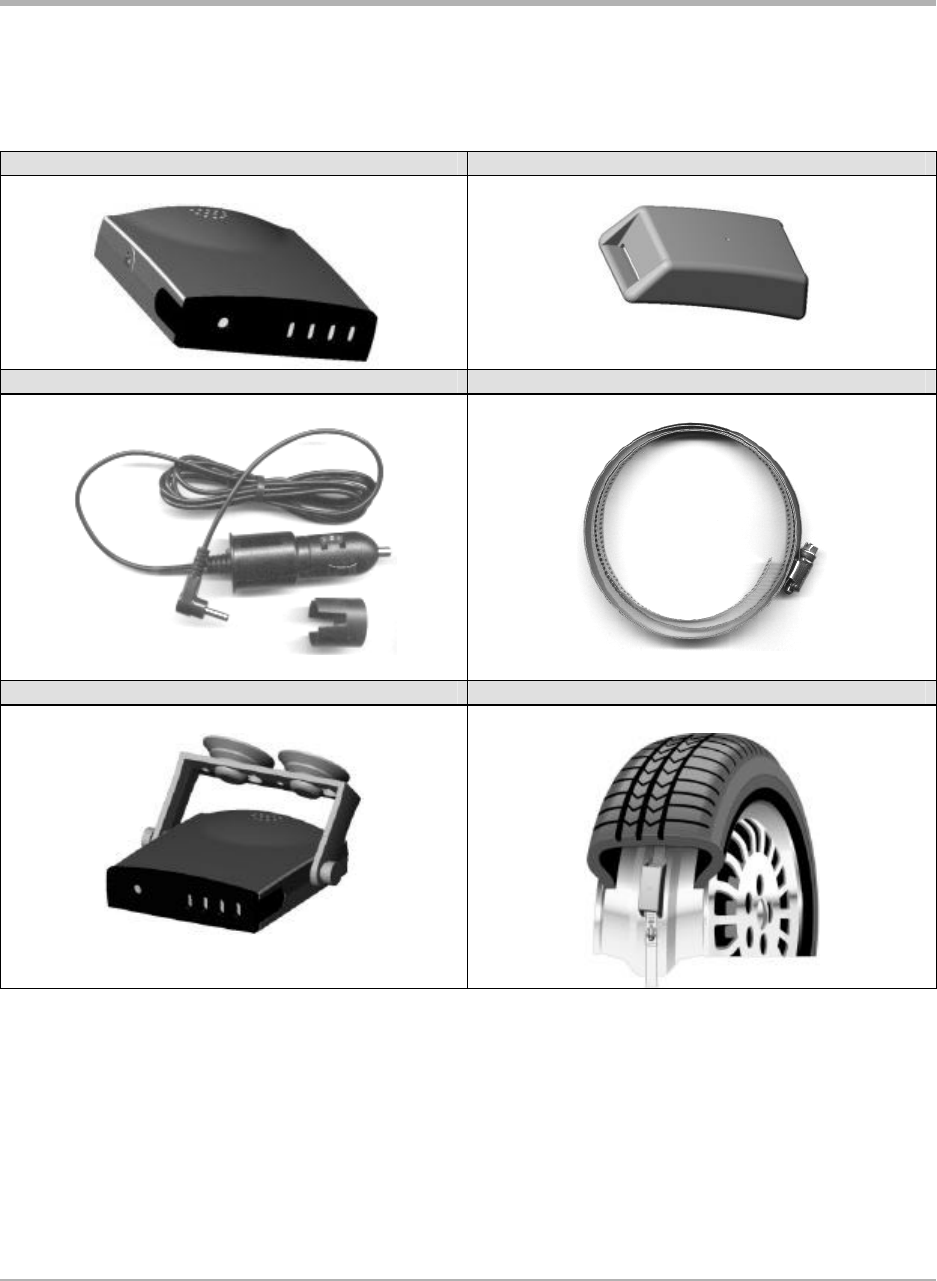
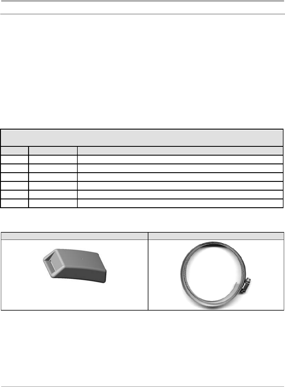
Component Images
Receiver Transmitter
Receiver cable and adaptor Strap for mounting transmitters
Receiver with mounting bracket and suction cups Transmitter mounted on wheel

SmarTire Systems Inc.
Tire Monitoring System Reference Manual
6/13/2000 Page 15 of 55
This manual is under review by SmarTire – DO NOT ISSUE
Pressure Alert Systems – 2 and 4 wheels – Multi-fit Valve Mount Transmitters
Kit # 060.2004 (4 wheel) Product B
Kit # 060.2002 (2 wheel) Product I
Overview
These kits contain a base receiver, two or four valve mounted transmitters, installation hardware
and documentation for use on tires with a pressure up to 83 PSI (gauge).
The transmitters transmit pressure and temperature data when the vehicle attains a speed of 10
kph. Tire pressure and temperature are checked every six seconds and data is transmitted every 5
minutes.
The receiver annunciates a pressure loss incident at two severity levels. The initial warning
occurs when the pressure has dropped a set amount below the required pressure. A second
warning occurs when the pressure has dropped to a level considered critical to the support of the
vehicle. The affected tire is identified with a colour coded indicator on the receiver,
corresponding to the same colour code on the valve of the respective tire.
An optional serial port can send transmitter data to another customer device.
To install the system attach a transmitter to a suitable valve and mount in the valve hole. Plug the
receiver into the cigarette lighter plug with the supplied cable.
Note: Valves are not included with the kit.

SmarTire Systems Inc.
Tire Monitoring System Reference Manual
6/13/2000 Page 16 of 55
This manual is under review by SmarTire – DO NOT ISSUE
Bill of Materials
060.2004 Pressure Alert Systems – 4 wheels – Multi-fit Valve Mount Transmitters
QTY PER
STOCK CODE Description
1
069.0001 INSTALLATION KIT
1
069.0002 POWER CABLE KIT
1
200.0059 RECEIVER -BASE-GENII
4
200.0065 TRANSMITTER-STRAP-GENII
1
276.0042 BOX - ELECTRONIC PARTS
1
276.0043 BAG TRANSMITTER SHIELD
1
700.0000 DOCUMENT KIT, GENII - BASIC
060.2002 Pressure Alert Systems – 2 wheels – Multi-fit Valve Mount Transmitters
QTY PER
STOCK CODE Description
1
069.0001 INSTALLATION KIT
1
069.0002 POWER CABLE KIT
1
200.0059 RECEIVER -BASE-GENII
2
200.0065 TRANSMITTER-STRAP-GENII
1
276.0042 BOX - ELECTRONIC PARTS
1
276.0043 BAG TRANSMITTER SHIELD
1
700.0000 DOCUMENT KIT, GENII - BASIC
SmarTire Systems Inc.
Tire Monitoring System Reference Manual
6/13/2000 Page 17 of 55
This manual is under review by SmarTire – DO NOT ISSUE
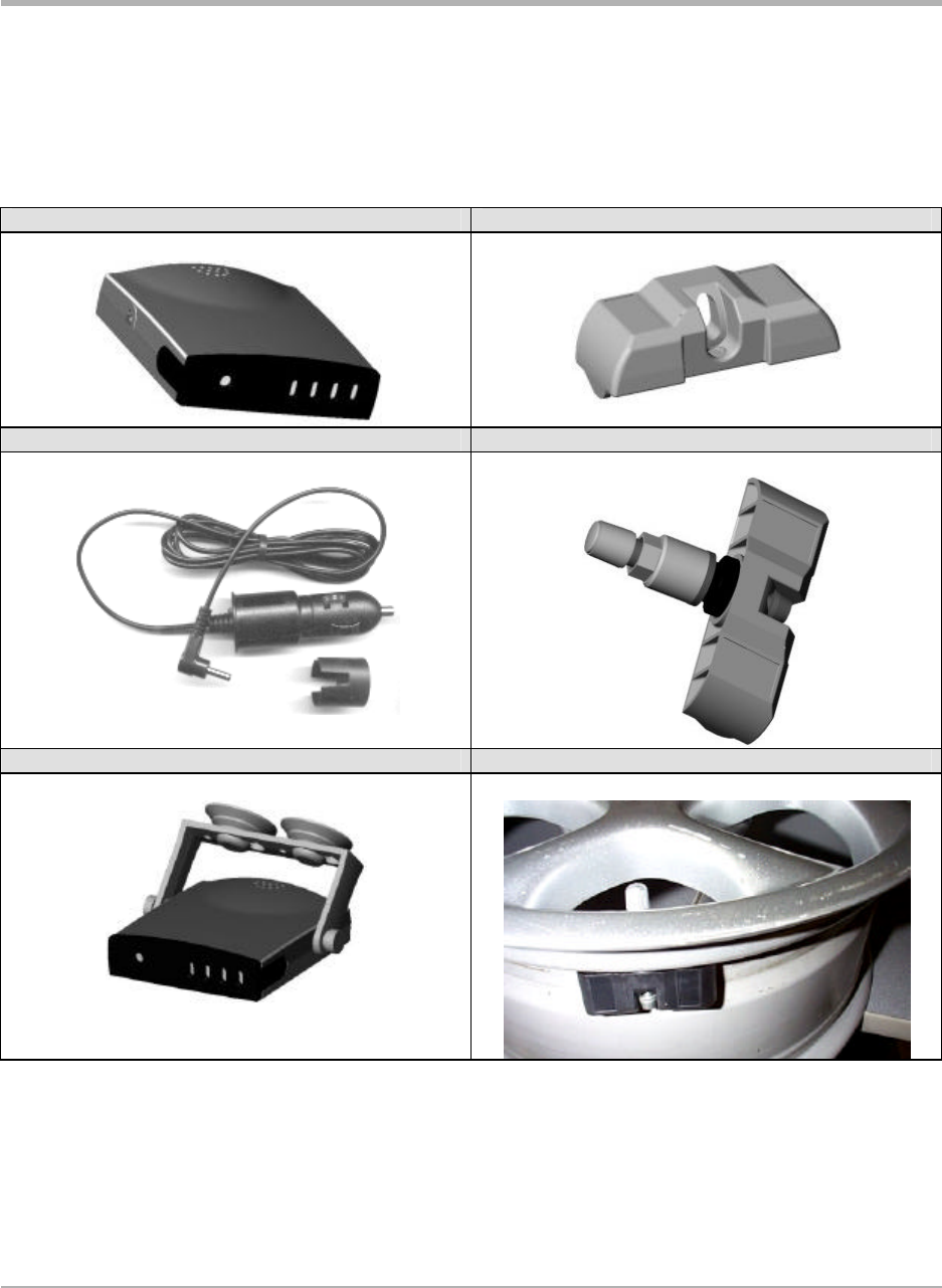
Component Images
NOTE: Valve not included in kit
Receiver Transmitter
Receiver cable and adaptor Transmitter mounted with valve
Receiver with mounting bracket and suction cups Transmitter mounted on wheel

SmarTire Systems Inc.
Tire Monitoring System Reference Manual
6/13/2000 Page 18 of 55
This manual is under review by SmarTire – DO NOT ISSUE
Pressure Alert Full Function Display
Kit # 061.4000 LCD-I
Kit # 061.4001 LCD-R
Overview
The full function display is used with any existing system to extend the functionality of the basic
tire pressure monitoring system up to 20 tire positions. It provides a digital pressure and
temperature readout as well as diagnostic data such as transmitter battery life for each tire. The
user can also set his own pressure warning levels and adjust other parameters to suit a particular
tire.
Two models of the LCD exist, differing by their method of connecting to the base receiver. The
LCD-I clips onto the front of the receiver, while LCD-R is connected via a 6 ft. interconnecting
cable.
To install, remove the basic receiver bezel. Clip the LCD-I unit onto the front of the base
receiver (or connect the cable in the case of the LCD-R).
SmarTire Systems Inc.
Tire Monitoring System Reference Manual
6/13/2000 Page 19 of 55
This manual is under review by SmarTire – DO NOT ISSUE
Bill of Materials
061.4000 Pressure Alert Full Function Display – Type I
QTY PER
STOCK CODE Description
1
200.0060 LCD DISPLAY UNIT - TYPE I
1
276.0042 BOX - ELECTRONIC PARTS
1
700.0001 DOCUMENT KIT, GENII - LCD
061.4001 Pressure Alert Full Function Display – Type R
QTY PER
STOCK CODE Description
1
200.0068 LCD DISPLAY UNIT - TYPE R
1
260.0096 CABLE REMOTE LCD
1
276.0042 BOX - ELECTRONIC PARTS
1
700.0001 DOCUMENT KIT, GENII - LCD
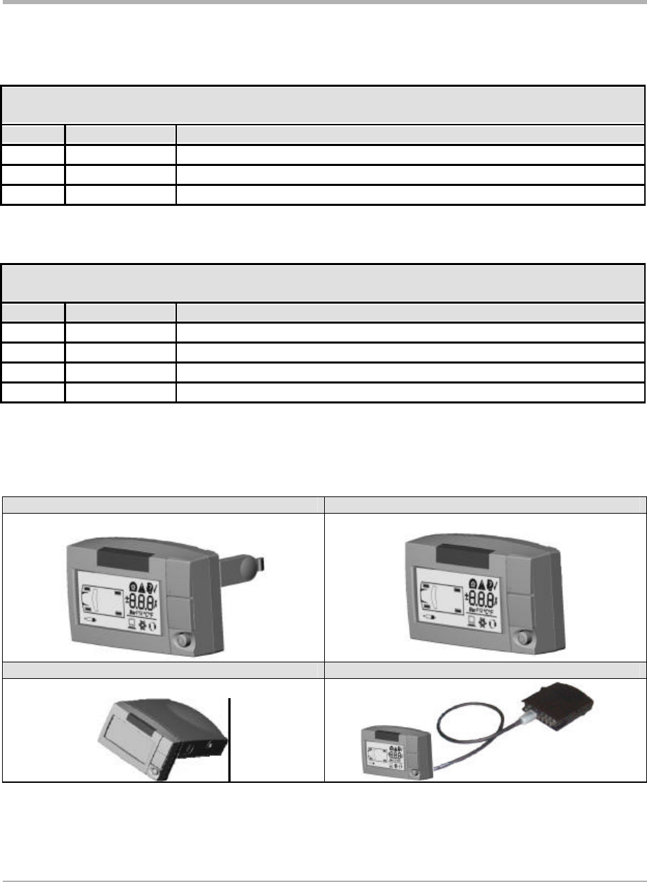
Component Images
LCD-I LCD-R
LCD-I mounted with receiver LCD-R with cable to receiver
SmarTire Systems Inc.
Tire Monitoring System Reference Manual
6/13/2000 Page 20 of 55
This manual is under review by SmarTire – DO NOT ISSUE
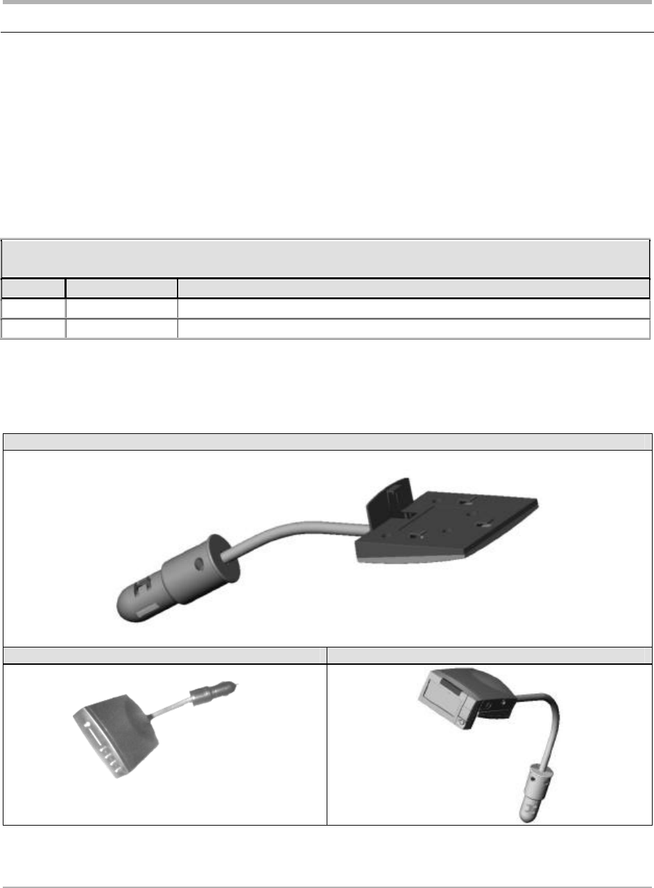
Pressure Alert Flexible Power Adaptor
Kit # 061.3000
Overview
A flexible power adapter is plugged into the cigarette lighter socket and the receiver is mounted
on it so that it can be positioned by the driver for the best viewing position.
Bill of Materials
061.3000 Pressure Alert Flexible Power Adaptor
QTY PER
STOCK CODE Description
1
200.0066 POWER SHOE ASSY-GOOSENECK-GII
1
276.0042 BOX - ELECTRONIC PARTS
Component Image
Flexible Power Adaptor (Gooseneck) Mount
Receiver –LCD mounted on Power Adaptor Receiver - LCD-R mounted on Power Adaptor
SmarTire Systems Inc.
Tire Monitoring System Reference Manual
6/13/2000 Page 21 of 55
This manual is under review by SmarTire – DO NOT ISSUE
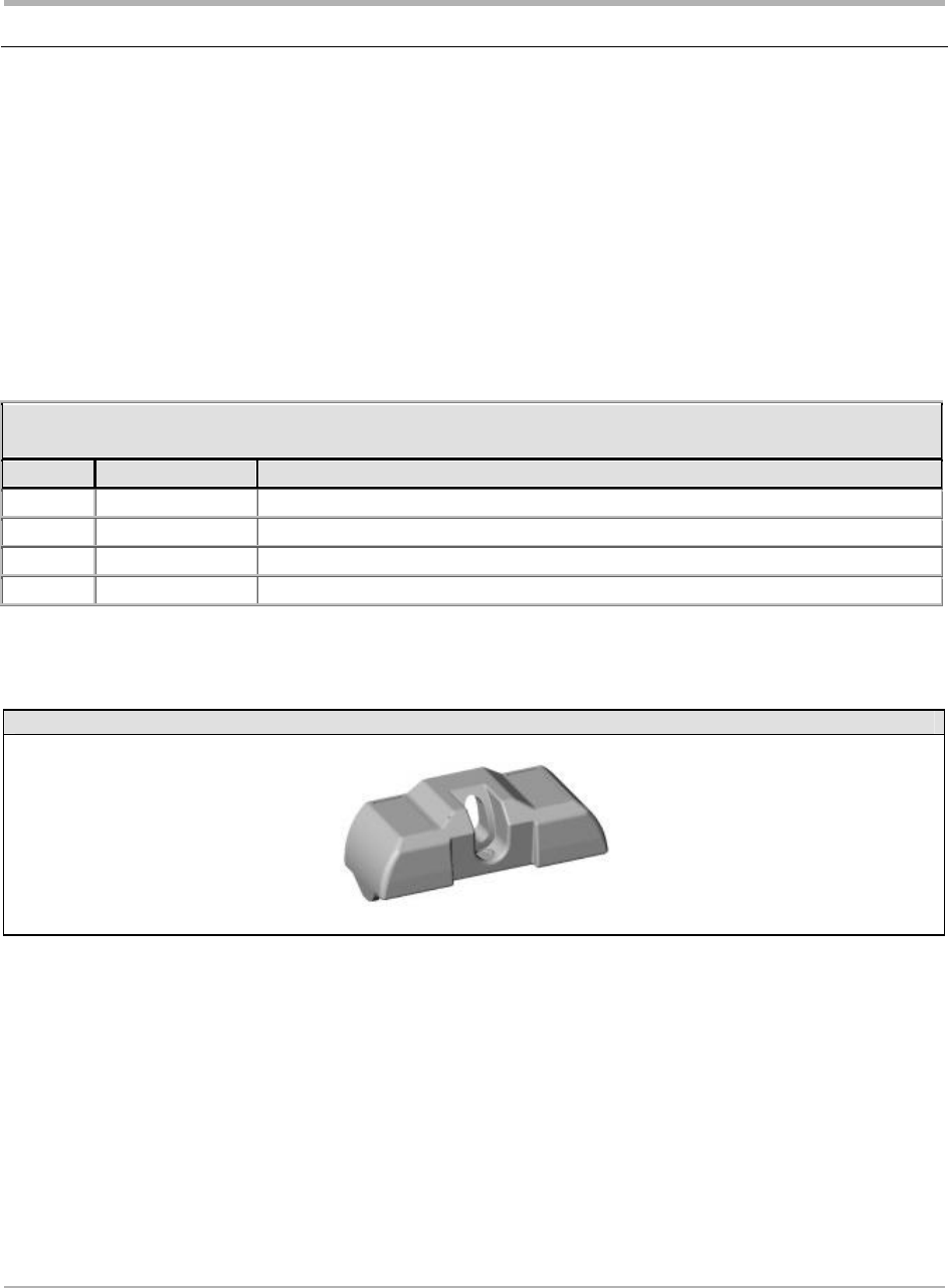
Pressure Alert Transmitter Kit – 2 - Multi-fit Strap Mount Transmitters
Kit # 061.1002
Overview
This kit consists of two strap-mount transmitters and installation hardware and instructions for
installation. It is intended to expand an existing installation.
Note: If this kit increases the total number of transmitters on a vehicle to greater than four, then
the full function display must also be installed to view all tire positions.
Bill of Materials
061.1002 Pressure Alert Transmitter Kit – 2 - Multi-fit Strap Mount Transmitters
QTY PER
STOCK CODE Description
2
200.0064 TRANSMITTER-STRAP-GENII
2
264.0115 STRAP - STAINLESS STEEL CLAMP
1
276.0041 BOX - PRODUCT KIT
1
276.0042 BOX - ELECTRONIC PARTS
1
276.0043 BAG TRANSMITTER SHIELD
1
700.0000 DOCUMENT KIT, GENII - BASIC
Component Image
Strap-mount transmitter Strap
SmarTire Systems Inc.
Tire Monitoring System Reference Manual
6/13/2000 Page 22 of 55
This manual is under review by SmarTire – DO NOT ISSUE
Pressure Alert Transmitter Kit – 2 - Multi-fit Valve Mount Transmitters
Kit # 061.2002
Overview
This kit consists of two strap-mount transmitters and installation hardware and instructions for
installation.
Note: If this kit increases the total number of transmitters on a vehicle to greater than four, then
the full function display must also be installed to view all tire positions.
Bill of Materials
061.2002 Pressure Alert Transmitter Kit – 2 - Multi-fit Valve Mount Transmitters
QTY PER
STOCK CODE Description
2
200.0065 TRANSMITTER-VALVE-GENII
1
276.0042 BOX - ELECTRONIC PARTS
1
276.0043 BAG TRANSMITTER SHIELD
1
700.0000 DOCUMENT KIT, GENII - BASIC
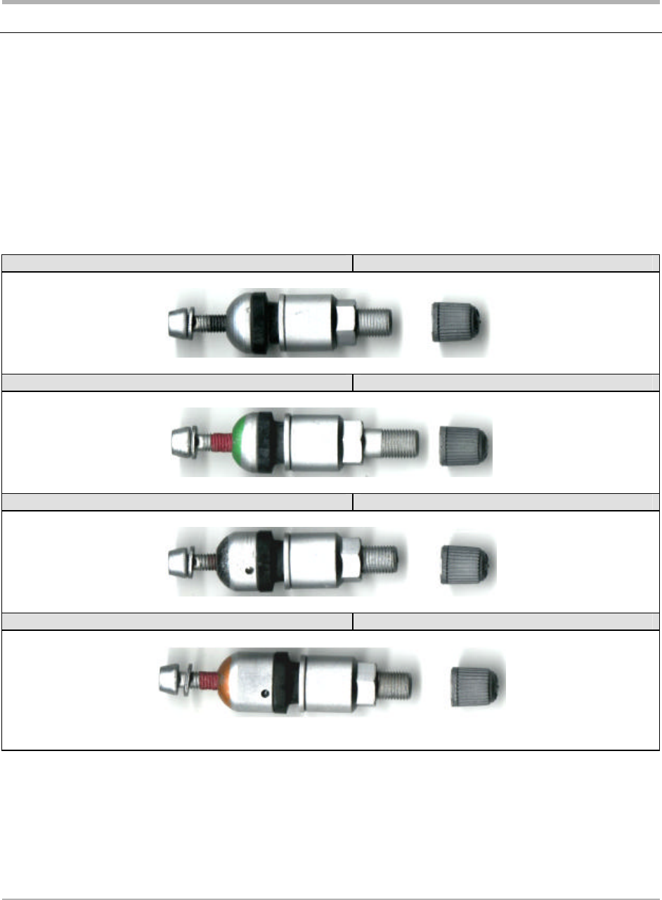
Component Image
Valve-mount transmitter
SmarTire Systems Inc.
Tire Monitoring System Reference Manual
6/13/2000 Page 23 of 55
This manual is under review by SmarTire – DO NOT ISSUE
Pressure Alert Valve Kits
Overview
These kits consist of two alligator valves of differing length for use with valve-mount transmitter
kits.
Component Image
Pressure Alert 2 Valve Kit – A Kit stock code 063.2000
Pressure Alert 2 Valve Kit – B Kit stock code 063.2001
Pressure Alert 2 Valve Kit – C Kit stock code 063.2002
Pressure Alert 2 Valve Kit – D Kit stock code 063.2003
SmarTire Systems Inc.
Tire Monitoring System Reference Manual
6/13/2000 Page 24 of 55
This manual is under review by SmarTire – DO NOT ISSUE
Receiver
Operation
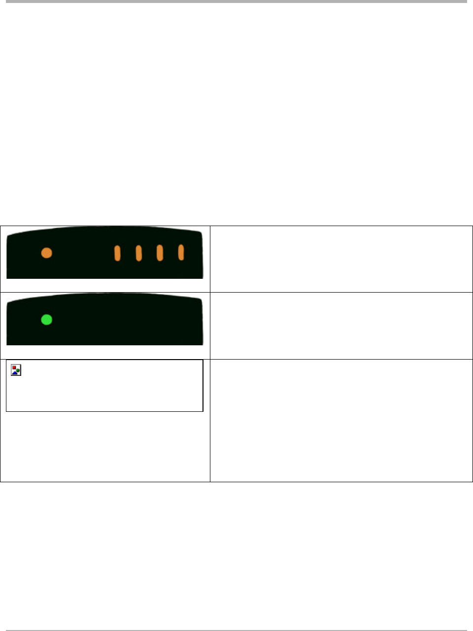
Ensure the receiver is plugged in. After power is applied the lights flash red, green, then amber.
They continue to flash amber until signals are received from the tire transmitters which transmit
pressure data shortly after the vehicle starts to move (at speeds greater than 10kph).. Then all will
turn off except the system light (left most light).
The receiver is preset to initiate warnings at two levels of tire pressure. Typical settings are 24
PSI to initiate a Low Pressure Alert and 18 PSI to initiate a Low Pressure Warning. Check
your kit documentation for the settings for your receiver.
When transmissions are received amber tire lights
turn off one at a time and finally system led turns
green and stays on steady.
System light is on green. Normal condition with no
alerts on any tire.
On Low Pressure Alert, there is a long beep, the
tire light turns red and stays red.
On Low Pressure Warning, the receiver beeps five
times, with accompanying red light. Then red light
flashes. After one minute receiver beeps five times.
Continues until tire condition is corrected. Then light
turns off.
Programming the Receiver
The factory settings for Low Pressure Alert and Low Pressure Warning can be changed with the
multi-function display. When a new transmitter is installed its ID must be programmed into the
receiver for it to be able to receive data. This is done with the Learn Mode of the multi-function
display.
SmarTire Systems Inc.
Tire Monitoring System Reference Manual
6/13/2000 Page 25 of 55
This manual is under review by SmarTire – DO NOT ISSUE
Multi-function Display (MFD)
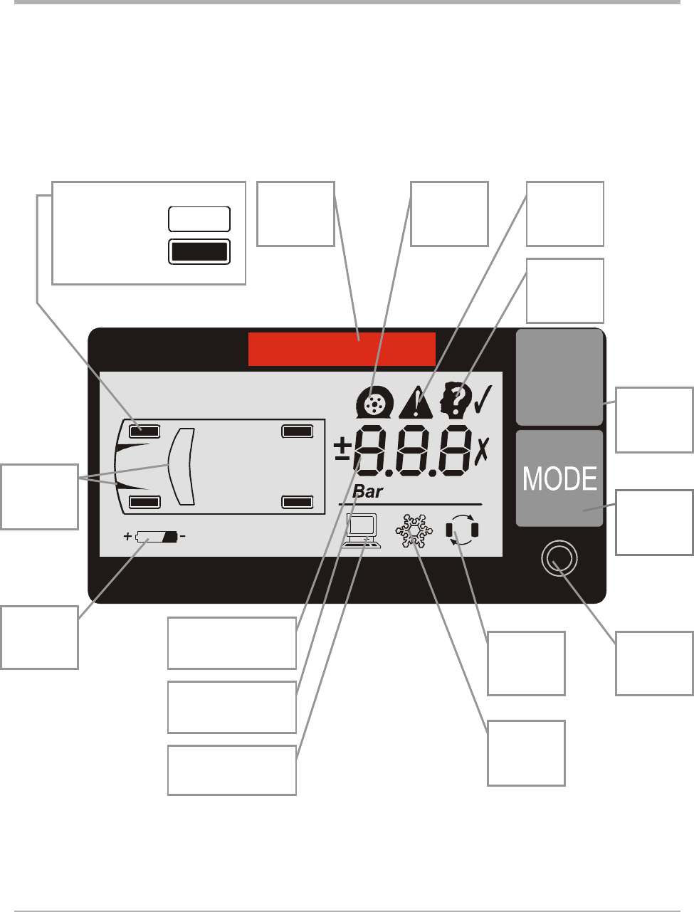
Controls and Display
ºC
PSI
ºF
TIRE
Towing
vehicle
indicator
Wheel position
NO data
Data received
Alarm
light
Tire
select
button
Program
select
button
Set
button
Tire
rotation
program
Cold
pressure
program
Programming
mode
Battery
indicator
Units of pressure
or temperature
Low
pressure
warning
Alert
indicator
Learn
mode
Numerical display
SmarTire Systems Inc.
Tire Monitoring System Reference Manual
6/13/2000 Page 26 of 55
This manual is under review by SmarTire – DO NOT ISSUE
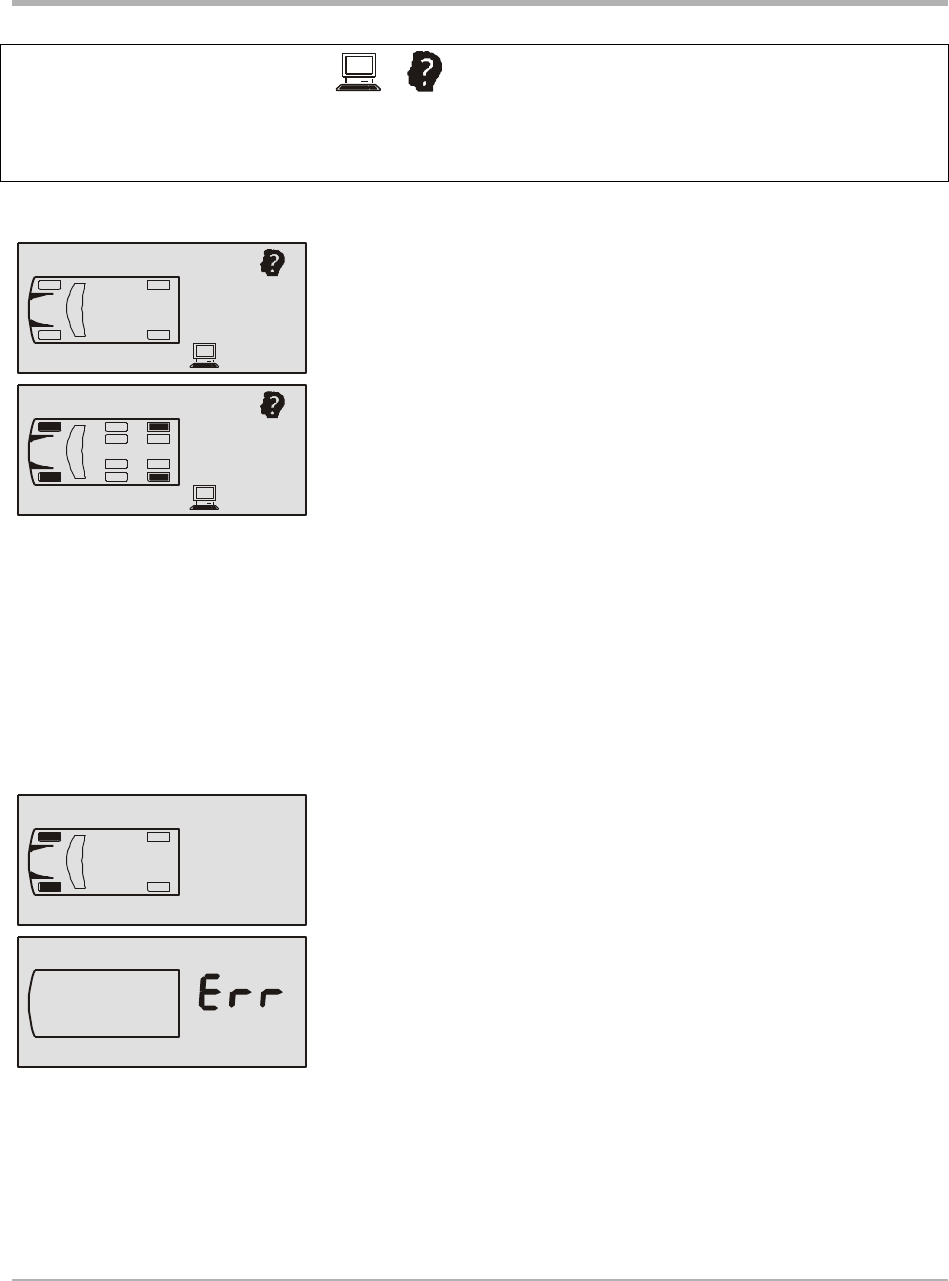
ICON Summary Table
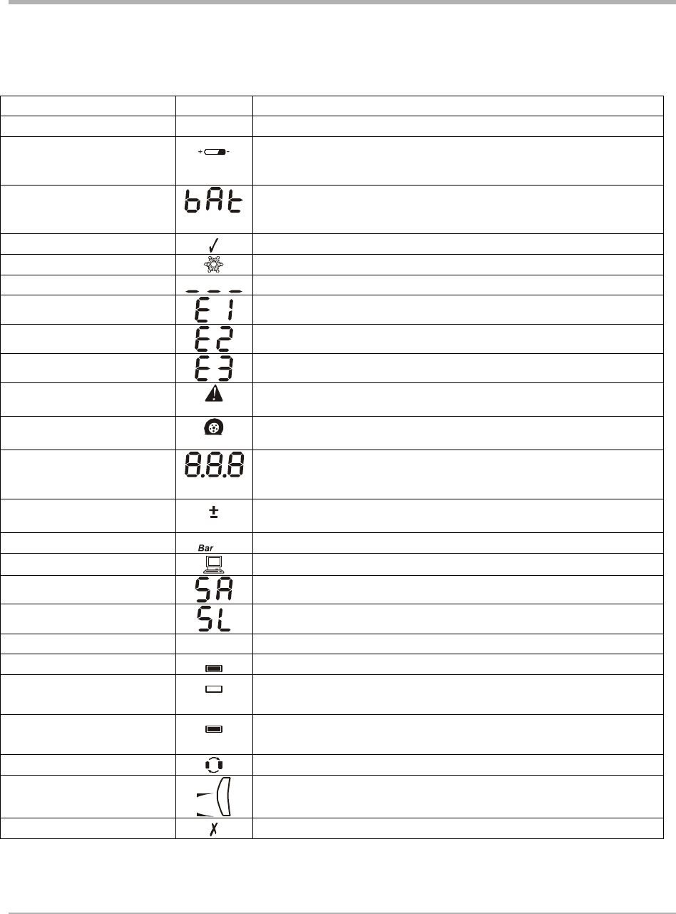
Name Icon Description
Battery Indicator Diagnostic mode, used to display battery
voltage for a selected sensor
Battery Text (“bat”)
Diagnostic mode, used to display battery
voltage for a selected sensor
Check Mark
Cold Pressure Setting Programming Mode, Cold Pressure Setting
No data received No data has been received (pressure, temperature or battery voltage)
Error Code (1) Sensor fault detected
Error Code (2) EEPROM fault
Error Code (3) Oscillator fault
Alert Display when a pressure alert has been detected. Used in
programming pressure alert limit.
Low Pressure Warning Display when a pressure warning has been detected. Used in
programming pressure warning limit.
Numeric Display
Displays numerical value of pressure, temperature and other
functions.
Pressure Deviation When on indicates that the numerical value of the display is a
pressure deviation.
Pressure Units
PSI
Pounds per square inch, Bars
Programming Mode LCD unit is in programming mode.
Sensor Alarm Sensor alarm is detected.
Slope During programming mode, setting of slope
Temperature Units
ºC
ºF
Celsius or Fahrenheit degrees are selected
Tire ID Learn Inner part flashes during ID learn mode
Tire Position
Programmed Tire position programmed, no data received
Tire Position Signal
Received Programmed tire position has received pressure data. (Inner part is
on steady)
Tire Rotation Programming mode, tire rotation mode
Towing vehicle
indicator
At least one of the 10 towing vehicle sensors has transmitted
X Mark

SmarTire Systems Inc.
Tire Monitoring System Reference Manual
6/13/2000 Page 27 of 55
This manual is under review by SmarTire – DO NOT ISSUE
Multi-function Display Operation Modes
The Multi-function display extends the functionality of the basic tire monitoring system from
four to twenty wheel positions. Digital readouts for pressure, temperature and temperature-
compensated pressure alerts are provided for each wheel position.
The MFD is required when the receiver must be programmed to accept the new ID number of a
replacement transmitter (Learn Mode) and to change the alert settings in the receiver.
Mode Summary
Stand-By mode System wheel data status and configuration
Regular mode View condition of a selected tire
Programming mode Program cold pressure, tire rotation, (3) alert settings, units
Diagnostic modes Slope, battery voltage, learn mode
Hidden Programming mode Set receiver low pressure alert threshold
Power Stages
The MFD has an energy saving feature that turns lights on to full intensity only when required to
display alert conditions or program the unit. The unit automatically switches to lower power
stages when no data transmissions or control activity is detected.
Active stage Back light is on, LEDs (alarm light and button lights) at full intensity.
Entered when any button is pressed or a valid packet is received in low-
power stage.
Half-power stage Back light is off, LEDs (alarm light and button lights) dimmed
Default stage after power-up. This stage is entered when no button is
pressed in 5 minutes
Low-power stage All lights are off (will activate when a button is pressed or transmission
received). Entered when no valid data packet is received in 20 minutes.
In stand-by mode the MFD will be in one of the three power stages. In all other modes the MFD
will be in the active power stage.
SmarTire Systems Inc.
Tire Monitoring System Reference Manual
6/13/2000 Page 28 of 55
This manual is under review by SmarTire – DO NOT ISSUE
Stand-By Mode
The stand-by mode is the state of the multi-function display showing the system status, i.e.
whether or not data has been received from installed transmitters. The screen is blank if no data
has been received from any transmitter. A button must be pressed in this mode to enter the other
modes. Specific data for a selected wheel position is obtained in the regular mode.
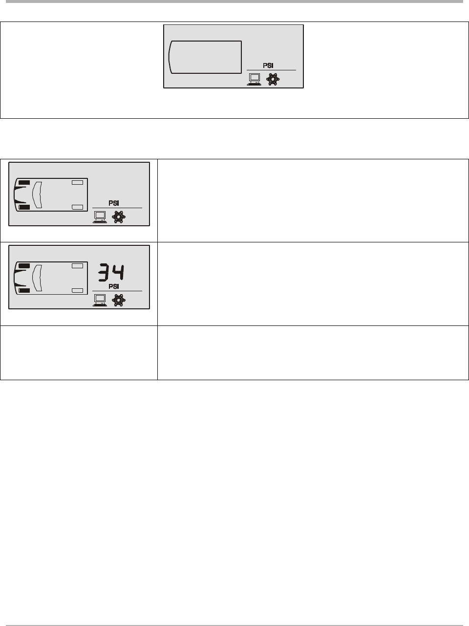
No data has been received from any installed transmitter.
The outline of an axle is displayed if at least a tire of that axle has a
pressure or temperature transmission.
The tire with pressure or temperature data received is filled in. The
outline of a tire with sensor fault flashes. If at least one of the ten
tires of the towing vehicle has a transmission, the louver and the
windshield are shown.
Regular Mode
This mode displays the specific pressure, temperature and alert condition of a selected wheel
position. The display can be set to show pressure in PSI or BAR and temperature in ºC or ºF.
Icons indicate the type of alert or warning.
From Stand-By mode press the TIRE button to enter the regular mode. Press the TIRE button to
cycle through the tires. Press the MODE button to cycle through the pressure, temperature, and
pressure deviation readings for a selected tire.
The alarm light will turn on if a tire with pressure or temperature problem is selected, and the
appropriate warning icons are displayed. Press the SET button or the TIRE and MODE buttons
together to go back to Stand-By mode. If no button is pressed in 5 minutes, the system will go
back to Stand-By mode.
A wheel position that has not transmitted data cannot be selected even if it was previously
programmed to accept a transmitter. The tire outline flashes when a sensor fault was detected.

SmarTire Systems Inc.
Tire Monitoring System Reference Manual
6/13/2000 Page 29 of 55
This manual is under review by SmarTire – DO NOT ISSUE
Programming Modes
Standard Operating Settings – Level 1
• Cold Pressure
• Tire Rotation
• Low Pressure Warning
• Pressure Deviation
• Temperature Alert
• Units Selection
To Enter Programming Mode
1. Enter Standby mode
2. Press Set button
3. Cold Pressure Program mode is entered
4. Use MODE button to scroll the possible settings.
5. Press Set button to get back into Standby mode.
SmarTire Systems Inc.
Tire Monitoring System Reference Manual
6/13/2000 Page 30 of 55
This manual is under review by SmarTire – DO NOT ISSUE
Cold Inflation Pressure
This function changes the cold inflation pressure for each axle.
To choose this mode press the TIRE button when the pressure
unit and the snowflake icon are displayed.
Press the TIRE button to scroll to the desired axle. The tires of
the selected axle are filled in.
Press the MODE button to view the current value.
Press the TIRE or MODE button to increase and decrease the
value respectively. Minimum is 5 PSI and maximum is 92 PSI.
When the desired value is set, press the SET button to save and
return to the axle selection menu. Scroll to a different axle
using the TIRE button again, or press the SET button to exit
this mode.
SmarTire Systems Inc.
Tire Monitoring System Reference Manual
6/13/2000 Page 31 of 55
This manual is under review by SmarTire – DO NOT ISSUE
Tire Rotation
After a tire rotation the receiver needs to be reconfigured to accept
existing tire ID numbers from the new locations. The color code on
the transmitter and valve correspond to a sensor number.
To choose this mode press the TIRE button when the tire
rotation icon is displayed
The tire outline indicates the installed sensors. The selected
tire location is filled-in. Use the TIRE button to scroll to the
desired tire location.
Press the MODE button to select it for editing. A number
representing each sensor is shown (e.g. a 2 corresponds to
sensor #2). Press the TIRE or MODE button to increase or
decrease the value respectively.
Press the SET button when the number representing the
desired sensor is achieved. This returns the display to the tire
selection menu. Scroll to a different tire location and edit the
sensor numbers. When all the changes are done, press the
SET button to save and exit this mode.
(ID 1 programmed in two
locations)
If more than one tire location contain the same sensor number,
the display will prompt an error with the conflicting tires
filled in and the associated sensor number.
Press SET to return the tire selection menu and make
necessary corrections.
NOTE:
After removing a sensor from the system using the Learn mode (see Diagnostic Modes below),
the sensor numbers may be changed.
SmarTire Systems Inc.
Tire Monitoring System Reference Manual
6/13/2000 Page 32 of 55
This manual is under review by SmarTire – DO NOT ISSUE
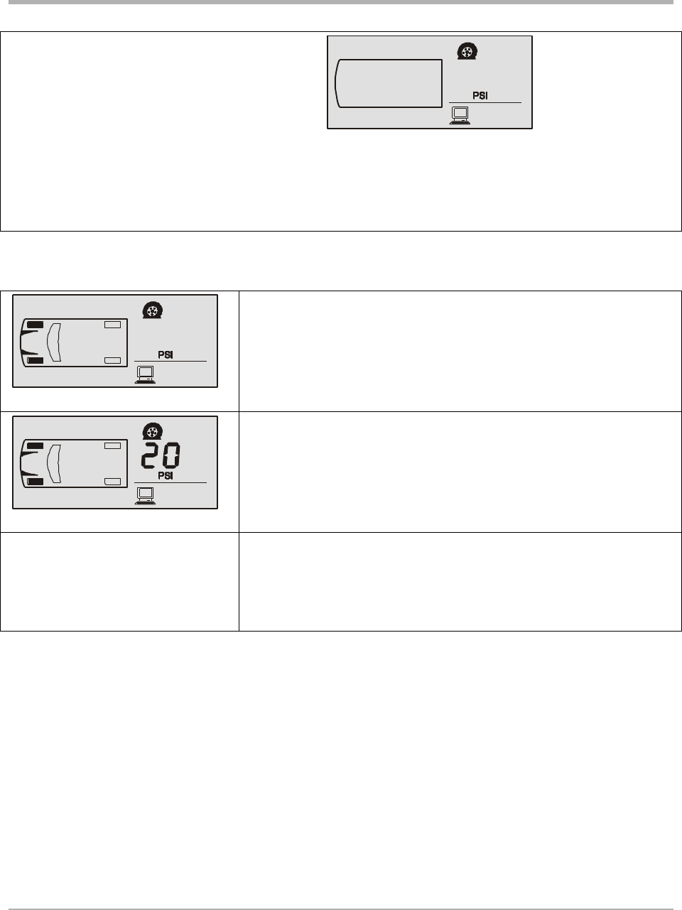
Low-Pressure Warning
This function changes the low-pressure warning
threshold for each axle.
To choose this mode press the TIRE button when the flat tire
icon and the pressure unit are displayed.
The tires of the selected axle are filled in. Use the TIRE
button to scroll to the desired axle.
Press the MODE button to select the axle. The current value
is shown. Press the TIRE or MODE button to increase or
decrease the value respectively. Lowest is 5 PSI. Highest is
92 PSI. Hold a button down to scroll the values rapidly.
When the desired value is set, press the SET button to save
and return to the axle selection menu. Scroll to a different
axle using the TIRE button again, or press the SET button to
exit this mode.
NOTE:
If this value is changed to exceed the low-pressure alert threshold, the alert threshold value will
be adjusted so that the warning threshold value is not greater than the alert threshold value.
SmarTire Systems Inc.
Tire Monitoring System Reference Manual
6/13/2000 Page 33 of 55
This manual is under review by SmarTire – DO NOT ISSUE
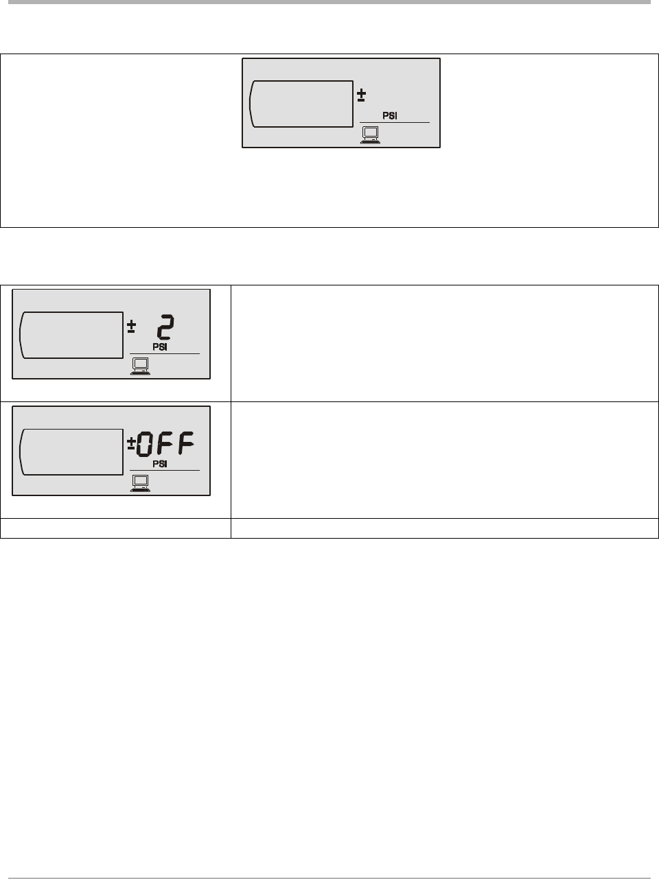
Pressure Deviation Alert
This function sets the pressure deviation alert threshold for all
tires.
To choose this mode press the TIRE button when the +/- icon
and the pressure unit are displayed.
Press the TIRE button to display the current value. Press the
TIRE or MODE buttons to increase or decrease the value
respectively.
Press the MODE button until the display shows OFF to
disable this feature.
Press the SET button to save the value.
SmarTire Systems Inc.
Tire Monitoring System Reference Manual
6/13/2000 Page 34 of 55
This manual is under review by SmarTire – DO NOT ISSUE
High Temperature Alert
Change or turn off the high-temperature alert threshold in this
mode.
To choose this mode press the TIRE button when the alert
icon and the temperature unit are displayed. The current value
of High Temperature Alert is displayed. Press the TIRE or
MODE button to increase or decrease the value respectively.
The minimum level is 86º F.
Press the MODE button until the display reads OFF to disable
this feature
Press the SET button to save the selected value.
Units
Use this mode to select the combination of pressure and
temperature units.
To choose this mode press the TIRE button when both the temperature and pressure units are
displayed.
Use the TIRE or MODE button to scroll through the four combinations of unit settings. Press the
SET button to save and exit this mode.
SmarTire Systems Inc.
Tire Monitoring System Reference Manual
6/13/2000 Page 35 of 55
This manual is under review by SmarTire – DO NOT ISSUE
Diagnostic Modes - Level 2
The following modes are found under the Diagnostic menu, which are accessed by holding the
SET button in Stand-By mode or Programming menu for 5 seconds. The MODE button is used
to scroll through each diagnostic mode.
• Slope (SL)
• Transmitter battery voltage (diagnostic function)
• Learn mode (set tire ID)
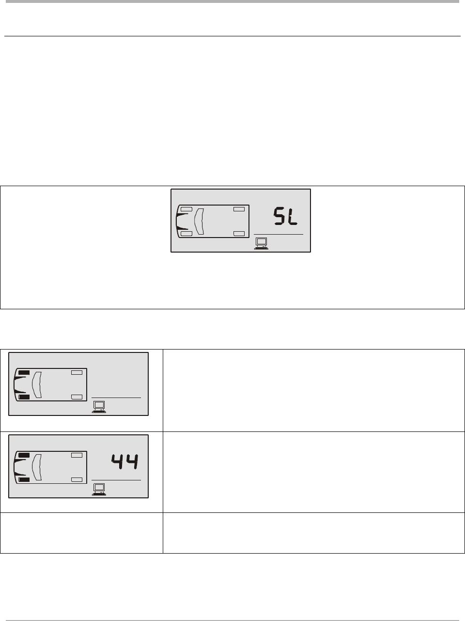
Slope
Use this mode to change the slope value used to calculate the
required pressure for each axle in this mode.
To choose this mode press the TIRE button when “SL” is
displayed.
Press the TIRE button to select an axle.
Press the MODE button to display the current value of slope
for the selected axle.
Press TIRE and MODE buttons to increase and decrease the
value respectively. The minimum value is 10 and the
maximum is 160.
Press the SET button to save the value.
Press the TIRE button to select another axle for programming.
SmarTire Systems Inc.
Tire Monitoring System Reference Manual
6/13/2000 Page 36 of 55
This manual is under review by SmarTire – DO NOT ISSUE
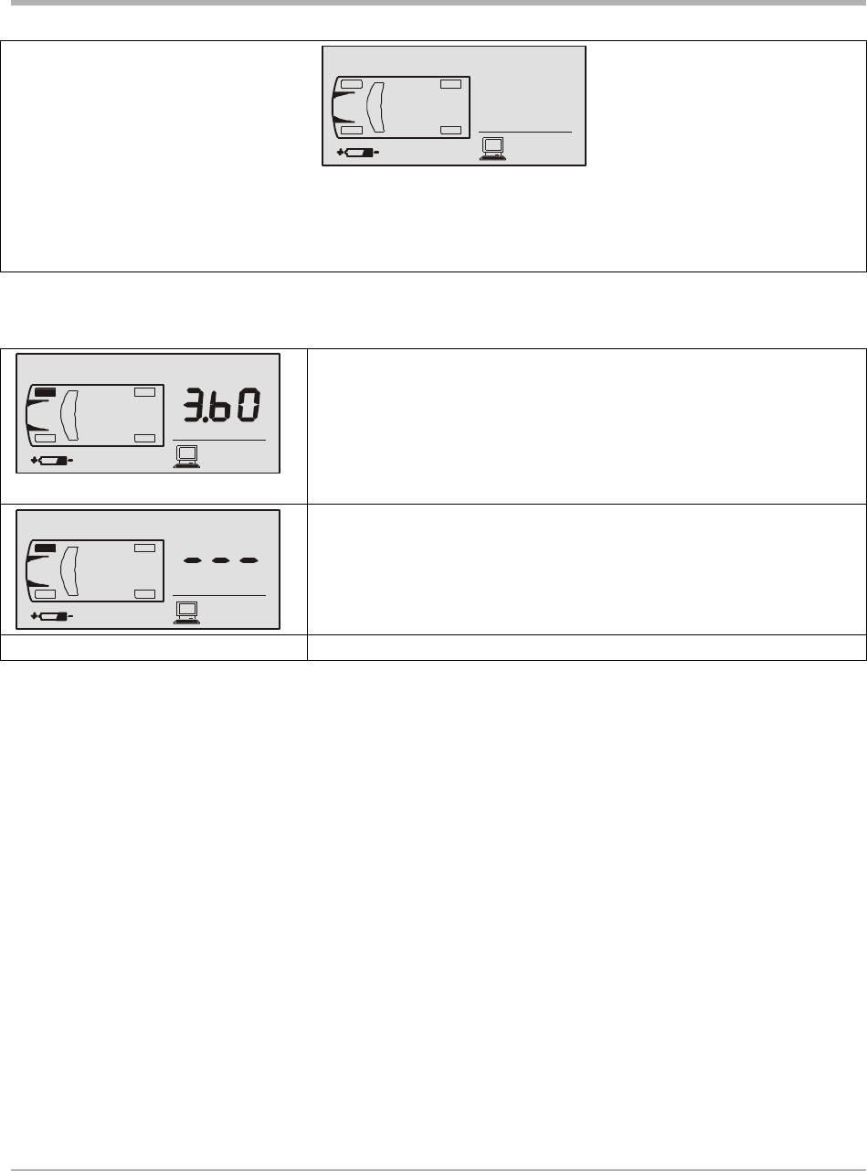
Battery Condition
Use this mode to check the battery voltage level for each
transmitter.
To view the transmitter battery voltage for a specific wheel
location press the TIRE button to scroll to each location.
If there is no voltage data received for a transmitter “---“ is
displayed.
Press the SET button to exit this mode.
SmarTire Systems Inc.
Tire Monitoring System Reference Manual
6/13/2000 Page 37 of 55
This manual is under review by SmarTire – DO NOT ISSUE
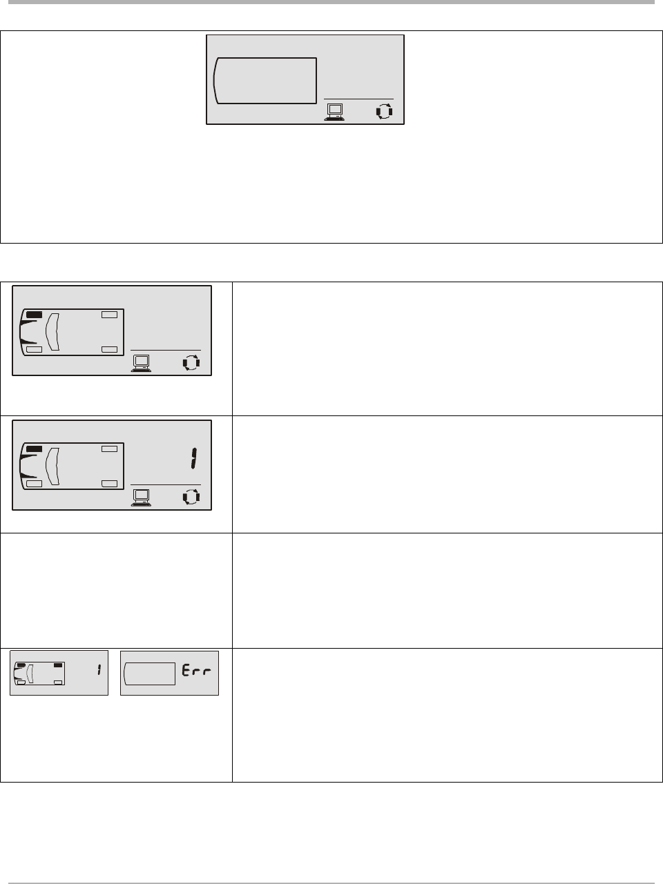
Learn
This mode is used to add or remove transmitters from the
system.
Press the MODE button to select the learn mode icon. The
currently installed positions are indicated with the tire outlines.
Press the TIRE button to display the ten possible wheel
positions for the towing vehicle. The currently installed
transmitter positions are now indicated with a filled in tire
indicator.
The outline of the wheel position to be programmed will flash.
Use the TIRE button to scroll to the desired position.
To add a new transmitter ID at the selected position provoke a
transmission from the transmitter. A beeper chirp and rapid
flashing of the alarm light indicate a valid packet was received.
The new ID is stored.
To remove the transmitter of the selected tire location press the
MODE button.
If more than one tire location contains the same sensor ID, the
display will prompt an error with the conflicting tires filled in.
If no error is found, the tire map and the sensor type flags in the
custom vehicle profile is updated. This operation is logged to
the black box. All the fault flags and diagnostic counters stored
in the EEPROM will be cleared. The system will reset and go
to Stand-By mode.
WARNING:
Make sure that no transmitter other than the desired one has transmitted before moving on to the
next tire location or exiting this mode.
SmarTire Systems Inc.
Tire Monitoring System Reference Manual
6/13/2000 Page 38 of 55
This manual is under review by SmarTire – DO NOT ISSUE
Hidden Programming Mode – Level 3
Low Pressure Alert
This mode sets the Low Pressure Alert and is used only by the
receiver.
Hold the SET button for 10 seconds. The screen will show the
diagnostic menu after 5 seconds. Another 5 seconds later, the
warning icon and the pressure unit are displayed
Use the TIRE button to scroll to the desired axle. The tires of
the selected axle are filled in.
Press the MODE button to display the current value of the
selected axle. Press the TIRE or MODE button to increase or
decrease the value respectively. The lowest value is
determined by the setting of the Low Pressure Warning. The
highest is 92 PSI.
When the desired value is set, press the SET button to save
and return to the axle selection menu.
Scroll to a different axle using the TIRE button or press the
SET button to exit this mode.
SmarTire Systems Inc.
Tire Monitoring System Reference Manual
6/13/2000 Page 39 of 55
This manual is under review by SmarTire – DO NOT ISSUE
Checking Tire Conditions
Startup
When power is applied a single beep accompanies all ICONS and lights turning on. Then screen
blanks and only button lights stay on green.
Vehicle motion initiates data transmission from the wheel transmitters. The MFD windshield
symbol (and louver) turn on, followed by each of the tire position icons. The windshield symbol
indicates that data is coming from the towing vehicle transmitters.
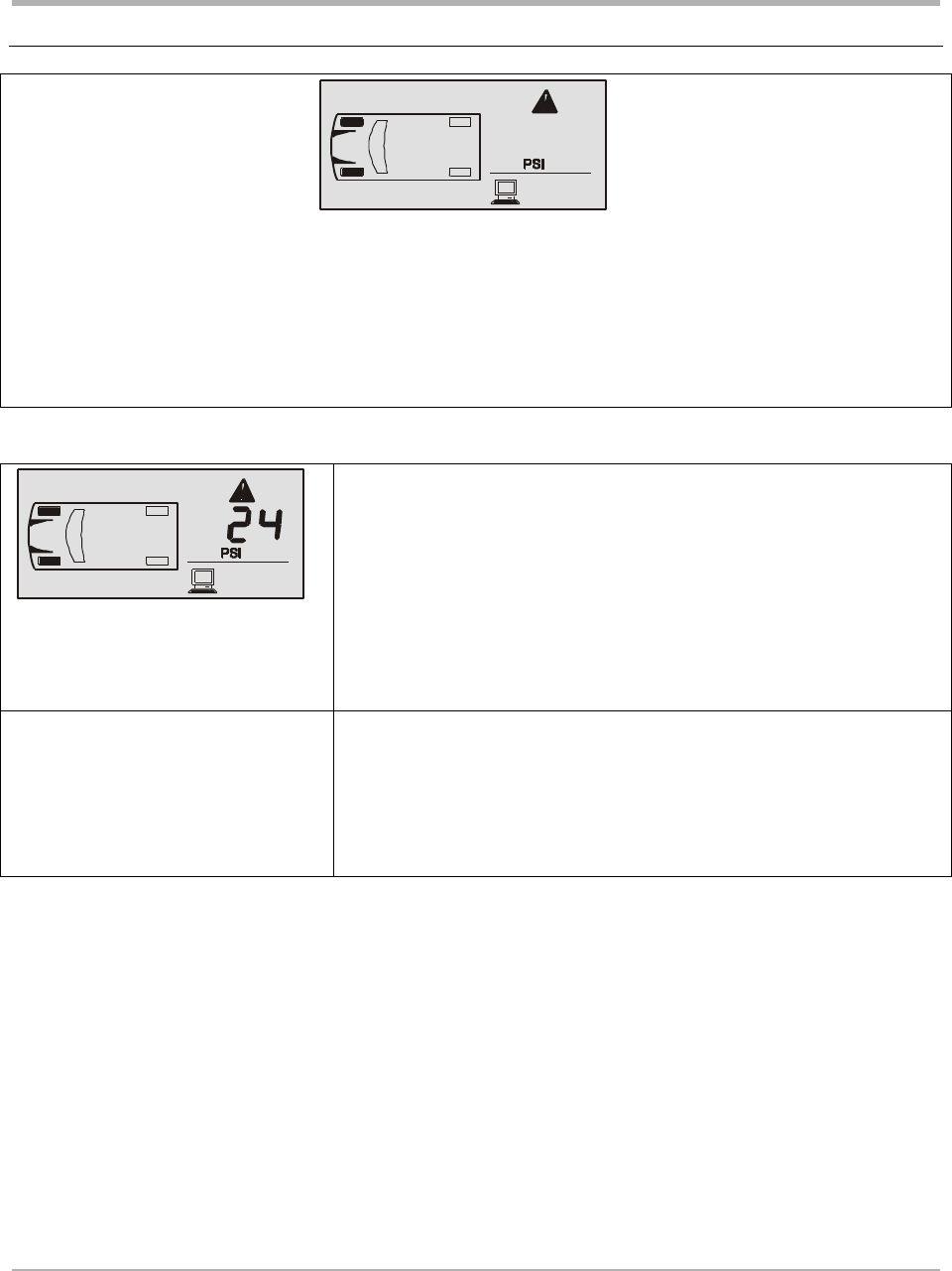
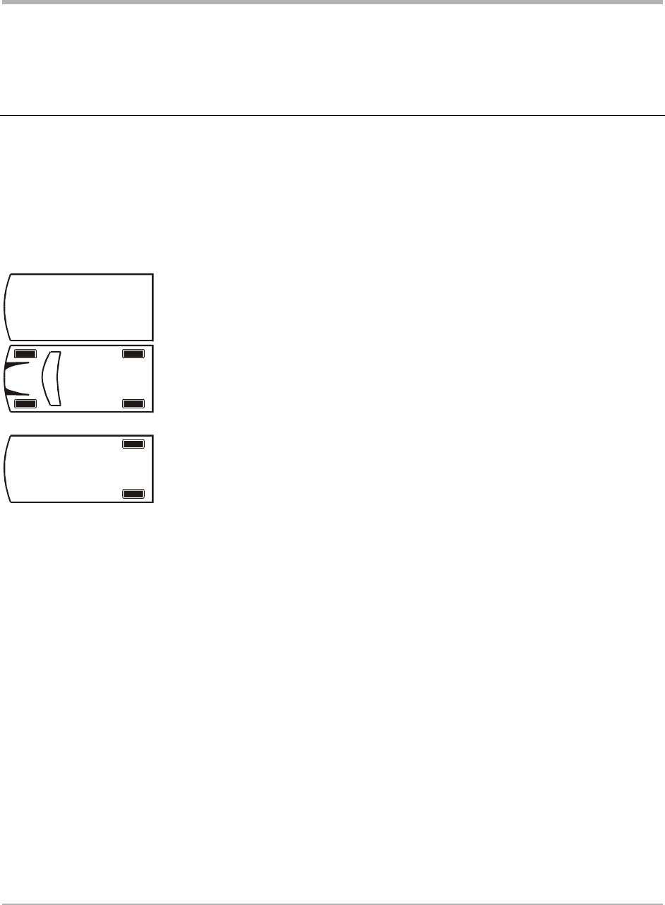
Standby mode Display after power up with no transmissions yet
received.
Standby mode This vehicle display indicates that transmissions
have been received from all four transmitters of
the towing vehicle.
Standby mode This vehicle display indicates that transmissions
have been received from both transmitters of the
towed vehicle.
SmarTire Systems Inc.
Tire Monitoring System Reference Manual
6/13/2000 Page 40 of 55
This manual is under review by SmarTire – DO NOT ISSUE
Detecting Abnormal Tire Pressure
The MFD alerts the driver of abnormal tire pressure with a Pressure Deviation Alert or a Low
Pressure Warning.
Understanding Temperature Compensated Pressure Readings
An important feature of the SmarTire (MFD) system is that pressure alerts are initiated from a
temperature compensated pressure calculation rather than on the actual pressure read by the
sensor.
The reference pressure, or “cold pressure” is the air pressure inside the tire inflated at room
temperature (18º C) to the tire manufacturer’s recommendation. A tire that heats up, for example
to 28º C, will increase the air temperature inside the tire, resulting in increased air pressure. For
example a normal or “required” pressure at 18º C may be 34 PSI and a normal pressure at 28º C
may be 36 PSI. Both pressure readings are correct at their respective temperatures.
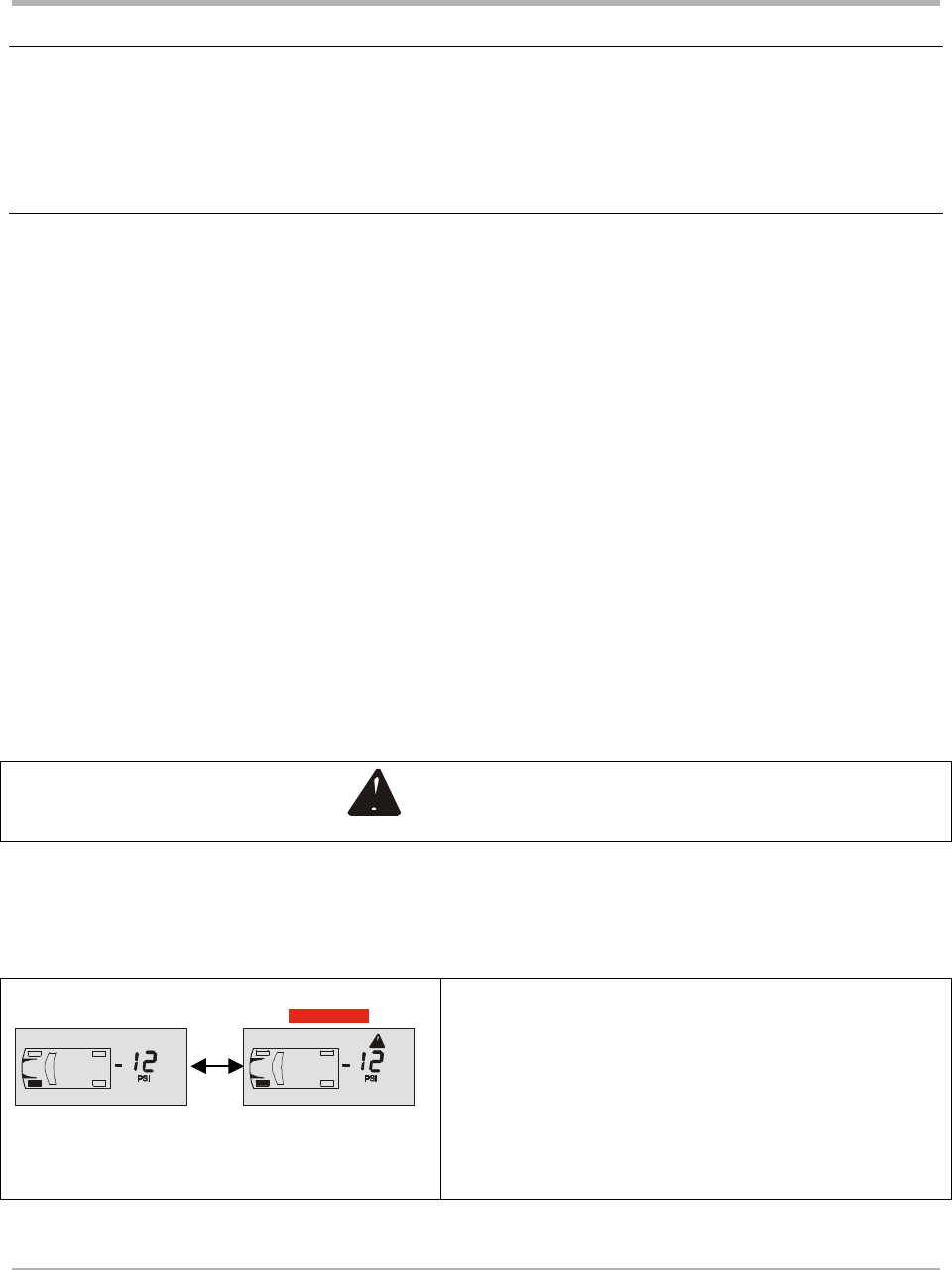
The amount of deviation from the required pressure (at any temperature) can be read by using the
Pressure Deviation mode of the MFD. If at any time you are uncertain that the Actual Pressure
reading on the display indicates the correct tire pressure, switch to the Pressure Deviation (+-)
readout. A blank display indicates that the reading on the display is the correct one. Any (+) or
(-) value indicates the tire pressure is incorrect by that value.
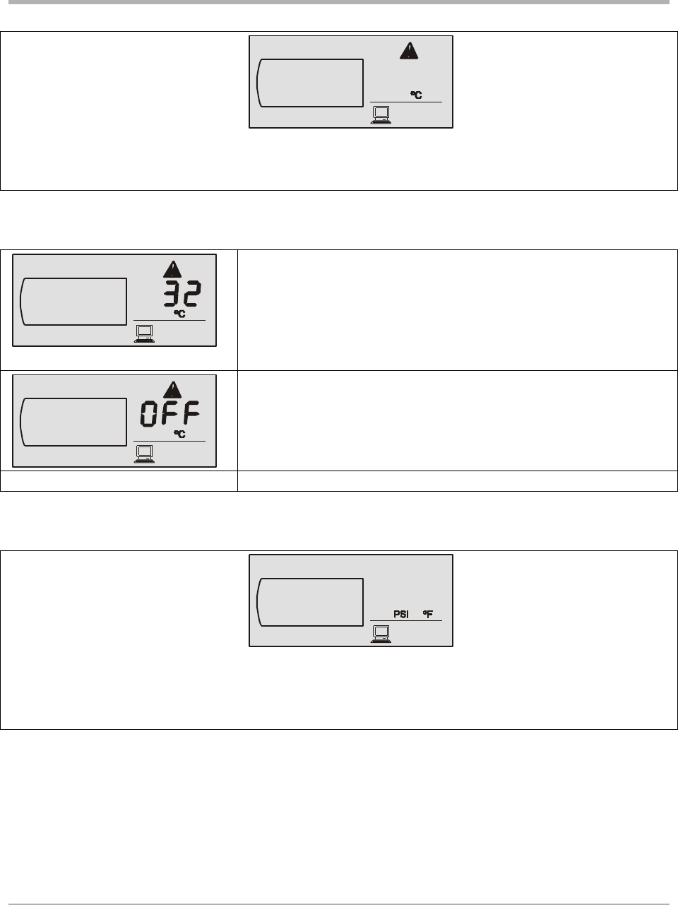
The Pressure Deviation Alert is temperature compensated.
The Low Pressure Warning is not temperature compensated.
Pressure Deviation Alert PSI | Bar
The Pressure Deviation Alert is initiated when the actual pressure of a tire deviates by more
than the amount programmed for the vehicle. For example this will occur if the MFD is set for
+- 2 PSI and the actual pressure drops to 24 PSI (from the required pressure of 34 PSI).
Alternating display
The MFD issues one beep. The alarm light and
alert icon flash on and off. The digital readout
displays the amount of deviation (-12 PSI) from
required pressure. Press any button to stop the
flashing and leave the alarm light on.
SmarTire Systems Inc.
Tire Monitoring System Reference Manual
6/13/2000 Page 41 of 55
This manual is under review by SmarTire – DO NOT ISSUE
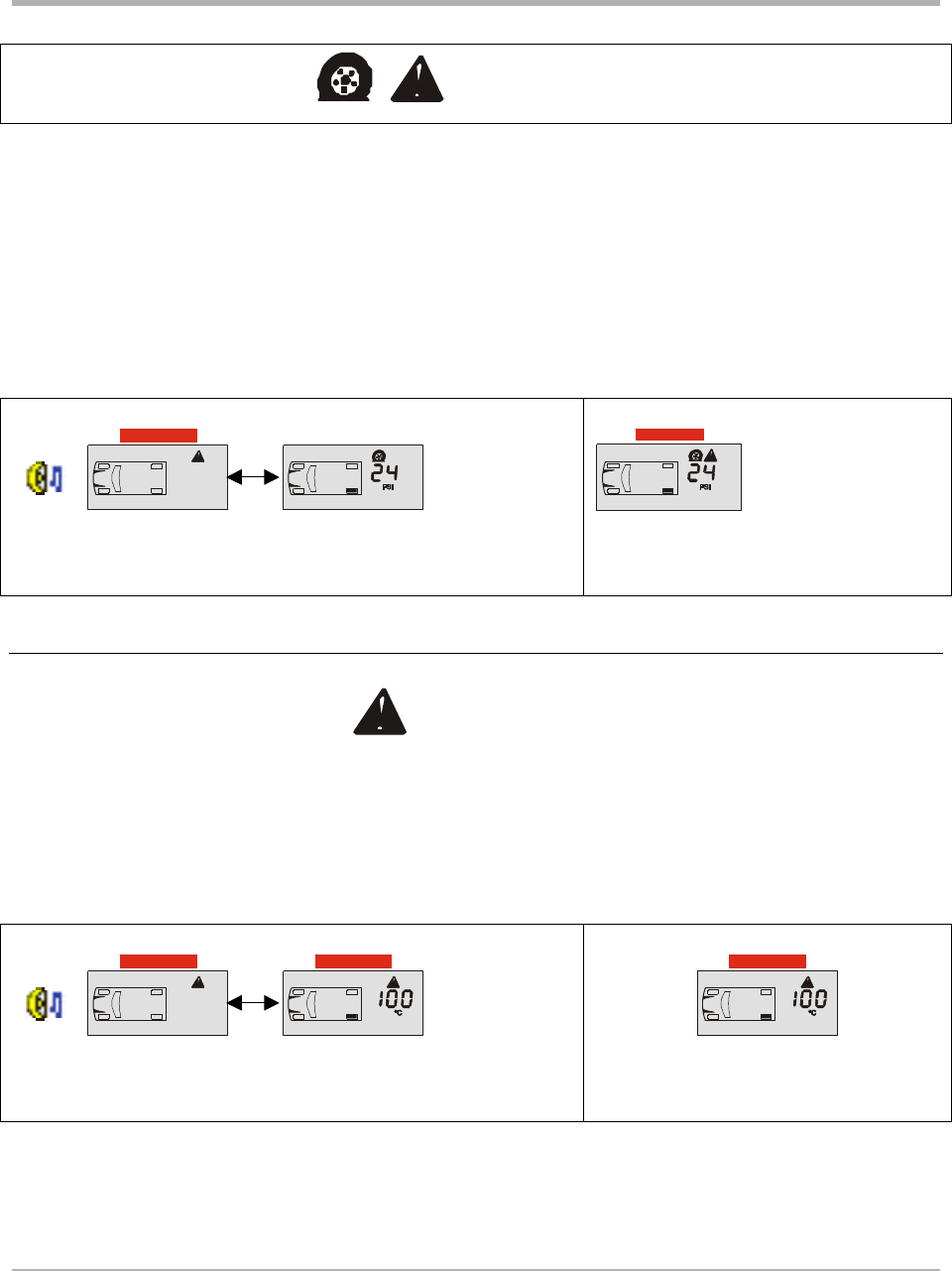
Low Pressure Warning PSI | Bar
A Low Pressure Warning is initiated when the actual pressure drops below the value
programmed for the wheel on that axle. For example if the setting is 26 PSI for the rear axle and
an actual pressure of 24 PSI is detected, the MFD will initiate a Low Pressure Warning.
The beeper turns on and off continuously and the alarm light flashes. Press a button to stop the
beeping and flashing. The display reverts to standby with the alarm light on continuously. Press
the tire button to find the affected tire. The flat tire icon, the alert icon, PSI, the pressure reading
and alarm light will all be on.
Alarm condition detected (beep and flashing light
alternates with pressure reading)
Display tire condition
Detecting Excessive Tire Air Temperature
High Temperature Warning º C | ºF
The MFD reads the temperature value sent by the wheel transmitters and compares it to a
programmed setting. If the actual temperature exceeds this setting the High Temperature Alert is
initiated.
Alarm condition detected (beep and flashing light
alternates with temperature reading)
Display tire condition

SmarTire Systems Inc.
Tire Monitoring System Reference Manual
6/13/2000 Page 42 of 55
This manual is under review by SmarTire – DO NOT ISSUE
Installation
Valve Mount Transmitter
Procedure Overview
1. Deflate and demount the tire.
2. Verify that the wheel can accept a valve mount transmitter
3. Install the transmitter.
4. Mount the tire and inflate to the proper pressure.
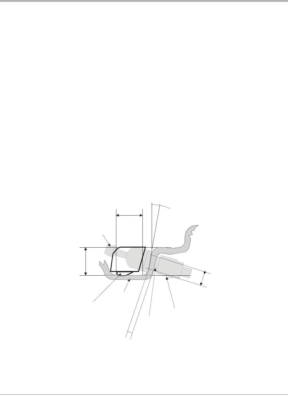
Alligator Valve Selection Process and Verification of Proper Assembly Fit
Internal Visual Inspection of the Wheel or Rim
1. Confirm location of drop-center:
• Is it nearer to front or back side of the wheel? –
• If near front, use the strap mount sensor.
• If near back, continue.
2. Confirm location of the valve:
• Is it beside the drop-center well, but at no more than a 10-degree angle? –
• If more than 10-degrees, use the strap mount sensor.
• If close, then continue.
3. Confirm diameter of valve hole in the wheel:
• Is it 0.453” (11.6MM)?
• [The only next closest standard sizes are 0.327” (8.38MM) and 0.625” (16.03MM)] –
• If smaller/larger, use the strap mount sensor.
• If confirmed 0.453” (11.6MM) diameter, then continue.
4. Confirm available clearance for the valve attachment nut:
• Is there 0.625” (16MM) diameter?
• [This clearance is adequate in most cases, but there are some wheels in the market where
we have found the anchor nut and washer to be 0.060” (1.5MM) too large.] –
• If less, then use the strap mount sensor.
• If more, then continue.
SmarTire Systems Inc.
Tire Monitoring System Reference Manual
6/13/2000 Page 43 of 55
This manual is under review by SmarTire – DO NOT ISSUE
5. Confirm maximum rim thickness at valve clamping area:
• Is it 0.156” (4MM)?
• [Normally not a problem with a 0.453” diameter valve hole] –
• If greater, then use the strap mount sensor.
• If less, then continue.
6. Confirm depth of the drop-center well near the valve hole:
• Is it 0.67” (17.3MM) below the humps of the bead seats?
• If shallower/deeper, then consider using the strap mount sensor.
• If OK, then continue.
7. Confirm width of the flat base of the drop-center well:
• Is it at least 0.85” (22MM)?
• If less, then installation of either the valve or strap mount sensor may not be possible.
• If OK, then continue.
8. Confirm relative position of the valve grommet-sealing surface of the valve hole of
the adjacent side or top edge of the drop-center well:
• Is valve hole recessed 0.25” (6MM)?
• If recessed considerably more, then use the strap mount sensor.
• If essentially flush or less, then continue.
0
.
4
5
3
"
0
.
1
5
6
"
Transmitter contact pads
Transmitter
attachment
screw
Valve anchor nut
Valve hole
Minimum drop
centre width =.85”
10 degrees
Rim thickness
Washer
Rim
Minumum
drop-centre
depth = .67”
Wall angle
Alligator Valve Selection and Fit Verification

SmarTire Systems Inc.
Tire Monitoring System Reference Manual
6/13/2000 Page 44 of 55
This manual is under review by SmarTire – DO NOT ISSUE
1. Start by using the valve assembly with longest of the three bases (Alligator #59.0054)
2. Remove the sensor attachment screw and install the valve body (into valve hole from the
front side), washer and nut. Finger-tighten the nut until grommet is evenly seated. Make
sure the fit of the valve body/grommet and the clearance of the washer/nut with respect to
wheel.
3. Place the sensor’s spherical mounting surface against the matching surface of the valve.
Pivot the sensor housing toward the bottom of the drop-center well until both contact
pads rest on the wheel. Confirm that the sensor’s only contact with the wheel is at the two
contact pads. Note the clearance between the sensor housing and the side of the drop-
center well, including the bottom radius. This space should be approximately 0.080”
(2MM).
• If clearance is greater than 0.25” (6MM), consider using a valve with a shorter base.
• If the clearance is between 0.25” and 0.44” (6.7MM and 11.3MM), switch to the valve
assembly with the next shorter base (Alligator #59.0044).
• If the clearance is greater than 0.44” (11.3MM), then utilize the valve assembly with the
shortest base (Alligator #59.0034).
• If no additional valve selections are available, then use the strap mount sensor.
4. Repeat the above procedure to verify housing clearance at both the top and bottom of the
drop-center well.
5. Check the position of the valve attachment hole in the base of the valve body relative to
the housing adjustment slot:
• Is hole completely visible with the housing firmly seated against both the wheel and
valve?
• If the hole is not completely visible, then use the strap mount sensor.
• If the hole is completely visible with some adjustment remaining, then continue.
6. Tighten valve anchor nut to a torque value of 36 in.-lb. (4+/-0.05Nm).
• [Note: It is very important to tighten the valve anchor nut to the defined torque value
prior to tightening the sensor attachment]
7. Assemble sensor housing and attachment screw onto the base of the valve. Before
tightening, hold sensor housing snugly against both the valve and the bottom of the
wheel’s drop-center well. Tighten the sensor attachment screw to a torque of 36 in.-lb.
(4+/-0.05Nm). Visually confirm that clearance remains between the top and bottom
corners of the sensor housing and the wheel surface.
SmarTire Systems Inc.
Tire Monitoring System Reference Manual
6/13/2000 Page 45 of 55
This manual is under review by SmarTire – DO NOT ISSUE
8. Finally, clearance between the sensor body and the side of the wheel’s drop-center well
should be at least 0.040” (1MM), and the housing contact pads at each end of the sensor
housing are seated against the base of the drop-center well.
9. Install appropriate colored washer onto valve stem if required.
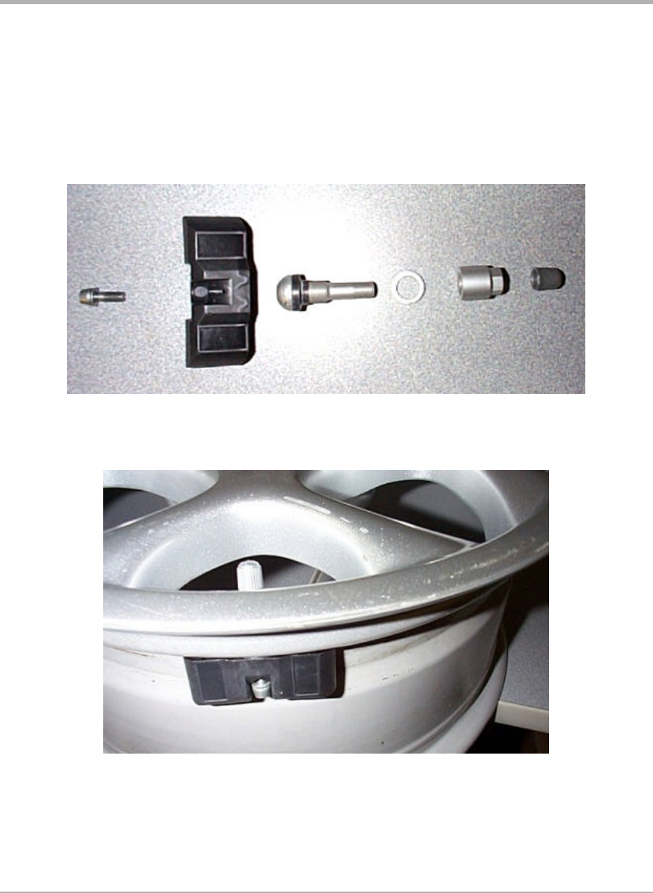
Transmitter and Valve Components
Transmitter/Valve Assembly on Wheel
SmarTire Systems Inc.
Tire Monitoring System Reference Manual
6/13/2000 Page 46 of 55
This manual is under review by SmarTire – DO NOT ISSUE
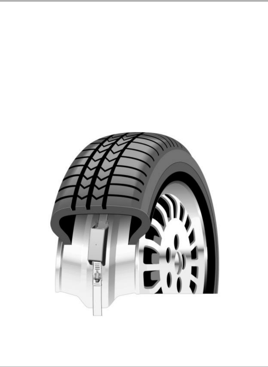
Strap Mount Transmitter
Process Overview
1. Ascertain that the wheel can accept a strap mount transmitter.
2. Deflate and demount the tire.
3. Install the transmitter
4. Mount the tire.
5. Inflate the tire to the proper pressure.
SmarTire Systems Inc.
Tire Monitoring System Reference Manual
6/13/2000 Page 47 of 55
This manual is under review by SmarTire – DO NOT ISSUE
Base Receiver Installation
The receiver needs an electrical connection to the vehicle 12 volt power and it needs to be
attached somewhere within view of the driver. The power connection may be made with the
power cable supplied with every receiver or by using the gooseneck power adapter.
The only consideration to watch for is that the receiver turns on when the vehicle is started.
When the receiver turns off the last pressure indications are not saved. New data must be
received from the wheel transmitters, i.e. the vehicle must be driven for 5 or more minutes to get
fresh data from all tires.
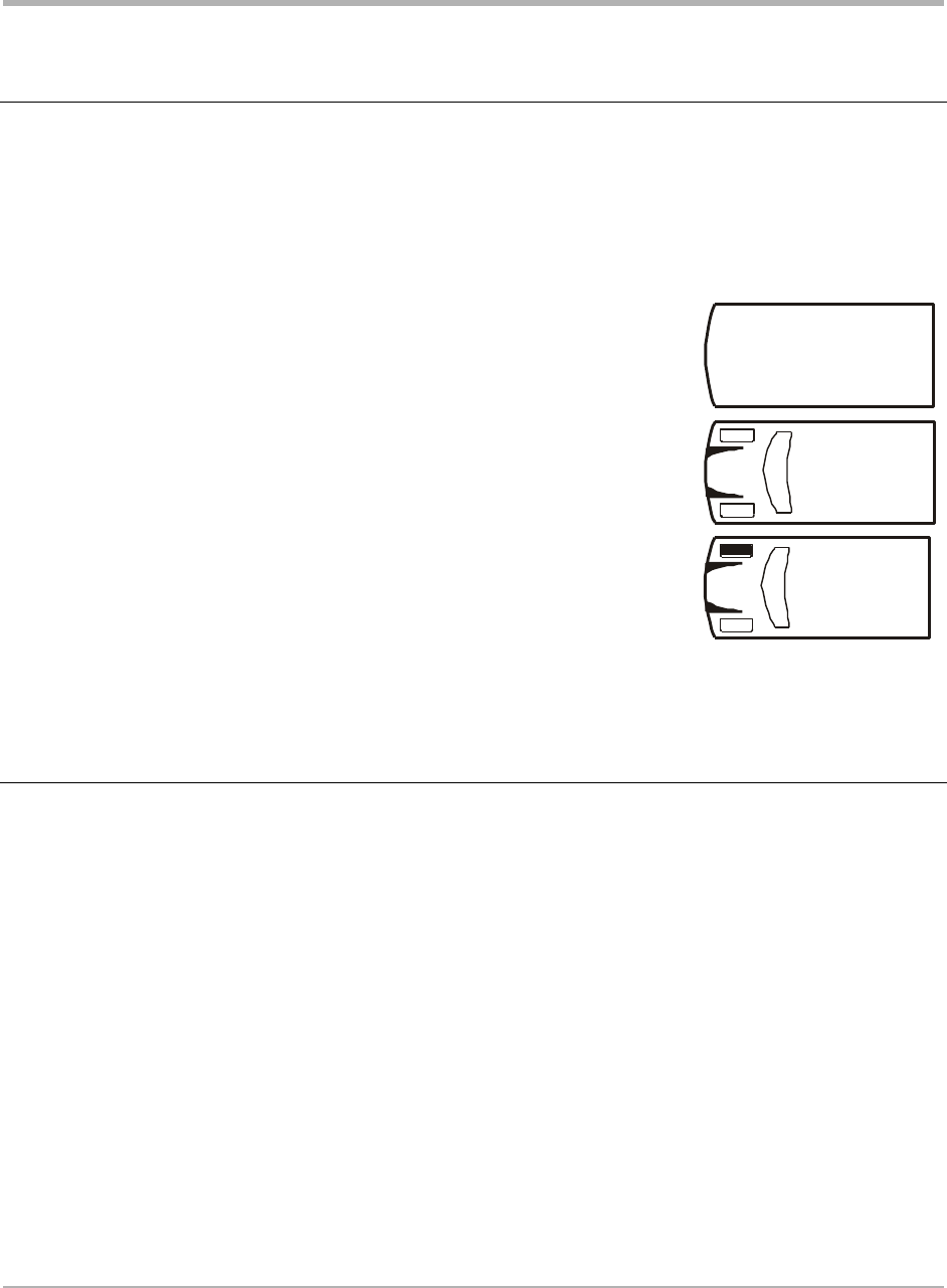
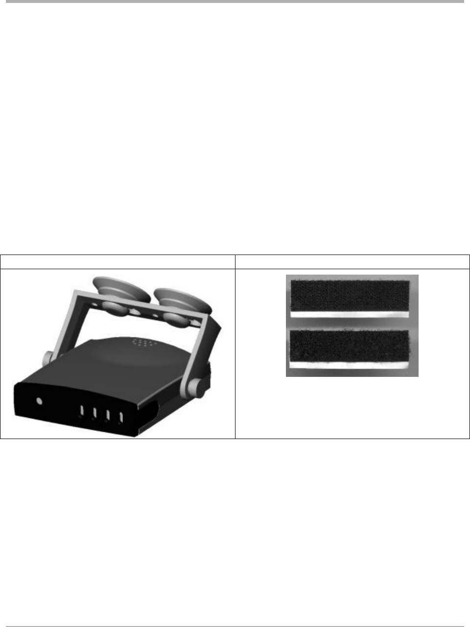
A bracket with suction cups supplied are intended for the receiver to be mounted on the
windshield in front of the driver. Two Velcro pads supplier enable the receiver to be attached in
other locations convenient to the driver.
Bracket and suction cup method Velcro pads
SmarTire Systems Inc.
Tire Monitoring System Reference Manual
6/13/2000 Page 48 of 55
This manual is under review by SmarTire – DO NOT ISSUE
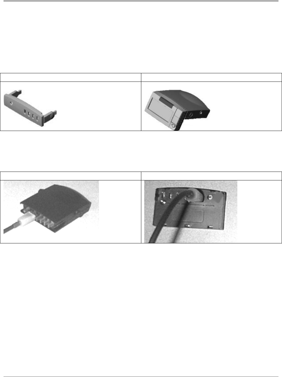
LCD unit Installation
The LCD unit comes in two models, one which integrates into the base receiver by clipping to its
front panel and other type which is connected remotely to the receiver via a 6’ cable.
To install the either LCD type, first remove the front bezel of the base receiver. Plug the LCD-I
type in place of the bezel.
Remove bezel from receiver Clip LCD-I onto front of receiver
For the remote version plug one end of the cable into the exposed connector on the base receiver
and the other end into the back of the LCD-R type. Observe proper polarity.
Receiver cable end plug LCD cable end connection
Power Shoe Installation
• Plug the power shoe connector into the cigarette lighter or an auxiliary plug in the
vehicle.
• Remove the battery cover from the back of the receiver.
• Push the receiver onto the power adaptor.
• Adjust the power adaptor flexible arm to a convenient viewing angle.

SmarTire Systems Inc.
Tire Monitoring System Reference Manual
6/13/2000 Page 49 of 55
This manual is under review by SmarTire – DO NOT ISSUE
Connection to External Systems
Interface; IPC to RS232
GEN II BATTERY CONNECTOR PIN DESIGNATIONS
Battery connector as seen from
the rear of PCB.
PIN # DESIGNATIONS
1 Open collector output (P2-4) - Diagnostic
2 E-I2C-CLK Communication (Clock)
3 Open collector output (P2-2) – Pressure alert
4 E-I2C-DAT Communication (Data)
5 No Connection
6 No Connection
7 Vin (supply voltage)
8 Ground
9 Battery pack input (4.5V)
10 Ground
Note:
a) All open collector outputs can drive up to 50 mA max.
b) Communication lines are level shift protected.
c) Vin (supply voltage 8.5Vdc to 26 Vdc max.
d) Battery pack is comprised of 3 – 1.5V AA batteries (4.5Vdc)
e) Connector used on Receiver PCB: SAMTEC:TML-105-02-G-D-RA
f) Mating connector for above: SAMTEC:SMS-105-01-G-D

SmarTire Systems Inc.
Tire Monitoring System Reference Manual
6/13/2000 Page 50 of 55
This manual is under review by SmarTire – DO NOT ISSUE
Technical Specifications
Base Receiver
Power Consumption 125 ma. maximum during alert
Operating Temperature Range -40° F to 185° F (-40° C to 85°C)
Storage Temperature Range -40° F to 185° F (-40° C to 85° C)
Frequency 433.92 MHZ ± 75 kHz
Size 2.85” H x 3.08” D x .87” W
Weight 67 gm
Operating Humidity 100 % non condensing
Number of indicators One multi-colored LED for each tire
LCD Full Function Display
Power Consumption 60 ma. maximum during alert (with receiver)
Operating Temperature Range -20° F to 185° F (-40° C to 85°C)
Storage Temperature Range -20° F to 185° F (-40° C to 85° C)
Size 2.8” W x .74” D x .1.64” H
Weight 43 gm.
Operating Humidity 100 % non condensing
Number of indicators Full function 3-digit LCD display
Power Shoe
To be determined
Battery Pack
System under design

SmarTire Systems Inc.
Tire Monitoring System Reference Manual
6/13/2000 Page 51 of 55
This manual is under review by SmarTire – DO NOT ISSUE
Transmitters – Strap Mount
Battery Life (Projected) 8.5 Years (normal vehicle use)
Operating temperature range -40° F to 185° F (-40° C to 85° C)
Storage temperature Range -40° F to 185° F (-40° C to 85° C)
Operating humidity 100%
Data transmitted Pressure, temperature, battery voltage
Data transmission rate Every 4 to 6 minutes (more frequently during a pressure loss
incident)
Weight To be determined
Size To be determined
Frequency 433.92 Mhz
Pressure Range 90 PSI absolute (75 PSI gauge)
Pressure accuracy +/- 2 PSI
Temperature accuracy +/- 3 ºC
Start-stop mode Vehicle motion greater than 10kph
Method of mounting Strap around the drop center of wheel
Transmitters – Valve Mount
Battery Life (Projected) 8.5 Years (normal vehicle use)
Operating temperature range -40° F to 185° F (-40° C to 85° C)
Storage temperature Range -40° F to 185° F (-40° C to 85° C)
Operating humidity 100%
Data transmitted Pressure, temperature, battery voltage
Data transmission rate Every 4 to 6 minutes (more frequently during a pressure loss
incident)
Pressure Range 90 PSI absolute (75 PSI gauge)
Weight 23 gm. (without valve which is 20 gm.)
Size To be determined
Frequency 433.92 Mhz
Pressure accuracy +/- 2 PSI
Temperature accuracy +/- 3 ºC
Start-stop mode Vehicle motion greater than 10kph
Method of mounting Mounted on valve

SmarTire Systems Inc.
Tire Monitoring System Reference Manual
6/13/2000 Page 52 of 55
This manual is under review by SmarTire – DO NOT ISSUE
Service and Warranty
Replacing a Transmitter – Valve and Strap Mount
1. Remove the existing transmitter
2. Install the new transmitter using the installation procedure in this manual.
3. Set the multi-function display into learn mode.
4. Spin the tire to provoke transmission.
5. Verify the system functions properly.
Replacing a Receiver
1. Unplug the existing receiver
2. Plug in a multi-function display and set into learn mode
3. Spin each tire in sequence to allow the new receiver to learn the ID codes of the
transmitters.
4. Verify the system functions properly.
Replacing a Full Function Display
1. Remove power.
2. Unplug the existing display.
3. Plug in the new one in its place.
SmarTire Service Policy – Handling Returned Materials
To return any materials to SmarTire, call SmarTire Service at 1-800- to receive a Returned
Material Authorization number (RMA). Follow instructions given by the service department for
packaging and shipping the product back.
Note: Shipments by air required the use of SmarTire approved shielding material to prevent
radio transmissions in the aircraft.

SmarTire Systems Inc.
Tire Monitoring System Reference Manual
6/13/2000 Page 53 of 55
This manual is under review by SmarTire – DO NOT ISSUE
Limited Warranty (US)
NOTE: This warranty statement is currently under revision.
This Warranty covers substantial manufacturer’s defects in workmanship and materials. It does
not cover any unit that is damaged beyond normal usage, was not properly installed, was
subjected to chemical contact, or other acts or omissions not sanctioned by the Owner’s Manual.
All components are covered for three (3) years and 50,000 miles following the date of
installation or five (5) years from date of manufacture, whichever comes first.
The SmarTire™ Warranty will be honored by any authorized SmarTire™ dealer.
The owner is required to provide dated proof of purchase. The authorized dealer will determine
if there is a warrantable condition associated with materials and/or manufacturing workmanship.
If a warrantable condition exists, the component will be replaced free of charge, shipping
prepaid. The owner is responsible for any labor and installation charges.
A completed Warranty Claim Form must be sent, postage prepaid, with the defective unit to
SmarTire.
The Warranty does not include any further obligation whatsoever, including but not limited to
actual installation of the replacement unit on the customer’s vehicle.
All other Warranties express or implied, are disclaimed. All collateral agreements, which
purport to modify this Limited Warranty, are of no effect. The absolute limit of liability is the
purchase price of the unit. SmarTire Systems Inc. is not liable for any direct, consequential,
indirect or punitive damages of any kind.
SOME STATES DO NOT ALLOW LIMITATIONS ON THE VALIDITY OR LENGTH OF
IMPLIED WARRANTIES, SO THE ABOVE LIMITATIONS MAY NOT APPLY TO YOU.
SOME STATES DO NOT ALLOW THE EXCLUSION OR LIMITATION OF INCIDENTAL
OR CONSEQUENTIAL DAMAGES, SO THE ABOVE LIMITATION OR EXCLUSION
MAY NOT APPLY TO YOU.
THIS WARRANTY GIVES YOU SPECIFIC LEGAL RIGHTS, AND YOU MAY HAVE
OTHER RIGHTS WHICH VARY FROM STATE TO STATE.

SmarTire Systems Inc.
Tire Monitoring System Reference Manual
6/13/2000 Page 54 of 55
This manual is under review by SmarTire – DO NOT ISSUE
Warranty (Canada)
NOTE: This warranty statement is currently under revision.
This Warranty covers substantial manufacturer’s defects in workmanship and materials. It does
not cover any unit that is damaged beyond normal usage, was not properly installed, was
subjected to chemical contact, or other acts or omissions not sanctioned by the Owner’s Manual.
All components are covered for three (3) years and 80,000 kilometers following the date of
installation or five (5) years from date of manufacture, whichever comes first.
The SmarTire™ Warranty will be honored by any authorized SmarTire™ dealer. The owner is
required to provide dated proof of purchase. The authorized dealer will determine if there is a
warrantable condition associated with materials and/or manufacturing workmanship. If a
warrantable condition exists, the component will be replaced free of charge, shipping prepaid, if
within the applicable warranty period. The owner is responsible for any labor and installation
charges.
This notice must be sent, postage prepaid, with the defective unit to SmarTire Systems Inc.
13151 Vanier Place, Suite 150, Richmond, British Columbia, CANADA, V6V 2J1. Phone 1-
604-276-9884.
The Warranty does not include any further obligation whatsoever, including but not limited to
actual installation of the replacement unit on the customer’s vehicle.
ALL OTHER WARRANTIES AND CONDITIONS, EXPRESS OR IMPLIED, INCLUDING
WARRANTIES AND CONDITIONS FOR MERCHANTABILITY, DURABILITY OR
FITNESS FOR PURPOSE, ARE DISCLAIMED. ALL COLLATERAL AGREEMENTS
WHICH MODIFY THIS SOLE WARRANTY ARE OF NO EFFECT. SMARTIRE SYSTEMS
INC. IS NOT LIABLE FOR ANY DIRECT, CONSEQUENTIAL, INDIRECT OR PUNITIVE
DAMAGES. THE ABSOLUTE LIMIT TO LIABILITY IS THE PURCHASE PRICE OF THE
UNIT.

SmarTire Systems Inc.
Tire Monitoring System Reference Manual
6/13/2000 Page 55 of 55
This manual is under review by SmarTire – DO NOT ISSUE
Regulatory Requirements
FCC Identification
See notice at beginning of manual.
European Requirements
To be determined on a country by country procedure.