Bendix Commercial Vehicle Systems TX433TV-2 433.92 MHz Valve Transmitter User Manual Owner Manual
Bendix Commercial Vehicle Systems LLC 433.92 MHz Valve Transmitter Owner Manual
Contents
- 1. Owner Manual
- 2. Installation Guide
Owner Manual

Tire Pressure Monitoring
System Owner’s Manual
017-1-0-0000000

1
SmarTire Systems Inc. reserves the right to change the contents of this manual at any time
and without notice. The information contained in this manual is proprietary and must not be
reproduced without prior consent from SmarTire Systems Inc.
© 2003 SmarTire Systems Inc.
TABLE OF CONTENTS
Notices 3
FCC Notice 3
European Regulations 4
System Scope of Use and Warnings 4
The SmarTire®System and Tire Maintenance 4
System Installation and Usage 4
Reacting to Alerts 4
Use of Chemicals 5
Power Connection 5
Getting Started 6
Receiver 7
Operation 8
How It Works 8
Installation 10
Transmitter Installation 10
Tools Required 10
Installing Transmitter on a Wheel 10
Mounting Tire with Transmitter on Wheel 12
De-mounting the Tire with Transmitter Installed 14
Receiver Installation 15
Service and Warranty 17
Component Part numbers 17
Troubleshooting 18
Factory Default Settings 18

32
SMARTIRE SYSTEMS INC.
Technical Specifications 19
Strap Mount Transmitter 19
Basic Receiver 20
US Warranty 20
Canadian Warranty 22
European Warranty 23
Appendix 24
Glossary 24
Optional Components 25
Notices
FCC NOTICE
This device complies with Part 15 of the FCC Rules. Operation is subject to the
following two conditions: (1) this device may not cause harmful interference, and
(2) this device must accept any interference received, including interference that
may cause undesired operation.
This equipment has been tested and found to comply with the limits for a Class B
digital device, pursuant to Part 15 of the FCC Rules. These limits are designed to
provide reasonable protection against harmful interference in a residential
installation. This equipment generates, uses and can radiate radio frequency energy
and, if not installed and used in accordance with the instructions, may cause harmful
interference to radio communications. However, there is no guarantee that
interference will not occur in a particular installation.
If this equipment does cause harmful interference to radio or television reception,
which can be determined by turning the equipment off and on, the user is
encouraged to try to correct the interference by one or more of the following
measures:
• Reorient or relocate the receiving antenna.
• Increase the separation between the equipment and Receiver.
• Connect the equipment into an outlet on a circuit different from that to which
the Receiver is connected.
• Consult the dealer or an experienced radio/TV technician for help.
Changes or modifications to this device without the express approval of SmarTire
Systems Inc. may void the user’s authority to use this device.

54
SMARTIRE SYSTEMS INC.
EUROPEAN REGULATIONS
This device complies with all European Electromagnetic compatibility regulations
(95/54/EC and EN300 220-1). The equipment has been tested and found to comply
with the above regulations, and in addition it meets the requirements for low
powered transmitters/receivers as defined by the relevant radio approval authority.
The regulations are designed to provide reasonable protection against harmful
interference or susceptibility. Changes made to this device without the express
approval of SmarTire Europe Ltd. may void the user’s authority to use this device.
SYSTEM SCOPE OF USE AND WARNINGS
The SmarTire System and Tire Maintenance
This system is a sensing device designed to identify and display tire operating data
and/or activate an alert or warning when pressure irregularities are detected. It is
the responsibility of the driver to react promptly and with discretion to alerts and
warnings. Abnormal tire inflation pressures should be corrected at the earliest
opportunity.
System Installation and Usage
Use of the SmarTire system requires that it has been properly installed and
programmed by personnel according to SmarTire Systems Inc. documentation. This
includes the Owner’s Manual and any supplementary installation instructions
included with system components.
This system is suitable for use in passenger and light truck tires up to maximum
cold inflation pressure of 65 psi or 4.46 bar.
Reacting to Alerts
When an alert or warning condition is detected, reduce vehicle speed to an
appropriate safe level and proceed to a safe stopping location or facility where
the tire can be inspected and serviced. The low pressure alert or warning indicates
that the air pressure has dropped to a selected minimum.
Use of Chemicals
Temporary resealing or reinflation products containing internal sealers or
propellants in any tire/wheel assembly may adversely affect the operation of the
Sensor/Transmitters.
Power Connection
If your Display is connected to an unkeyed cigarette lighter socket unplug it when
you park the vehicle for extended periods (more than three days) to avoid draining
the battery or triggering a false diagnostic alert.
7
Getting Started
Congratulations! As the owner of this state-of-the-art wireless tire pressure
monitoring system, you will enjoy the improved convenience and benefits of having
tire pressure information automatically monitored while you are driving.
The SmarTire system consists of wheel mounted Sensor/Transmitters inside each
tire which measure contained air pressure and temperature and transmit this data
to a Receiver within view of the driver (the optional Full Function Display is
required to display pressure and temperature).
Having carried out the correct installation procedure (see Installation section in
this manual), the SmarTire system is ready to use.
Transmitter Basic Receiver
6
SMARTIRE SYSTEMS INC.
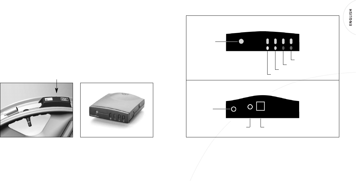
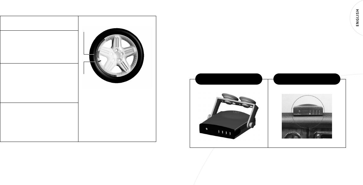
RECEIVER
Front indicator panel
Back
Note: Each color on front indicator panel refers to a Transmitter with a
corresponding washer color. Color washer must stay with the corresponding color
Transmitter during tire rotation.
Tire – Green
System light
Tire – Red
Tire – Blue
Tire – Yellow
Diagnostic
port
Note: Shown with
rear cover removed.
Power Power adapter
interface
98
SMARTIRE SYSTEMS INC.
Operation
HOW IT WORKS
The system operates continuously, transmitting air pressure and temperature data,
• At approximately 5 minute intervals when the vehicle is moving faster than 6 mph
(10 kph), unless pressure changes, then data is transmitted within 7 seconds.
• Every 20 minutes when the vehicle is parked and pressure drops to 18 psi
(1.25 bar) or lower.
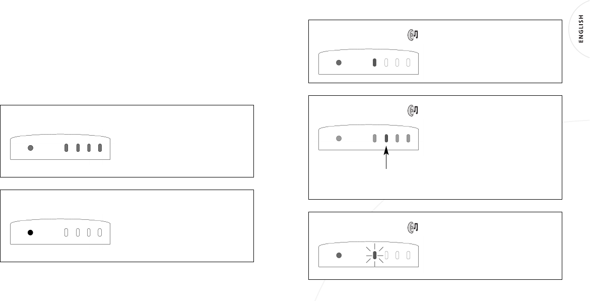
After the Receiver is turned on, the lights
flash red, green, then amber, waiting for
Transmitter data.
In Motion: When transmissions are
received amber tire lights turn off one at
a time and the system light turns green.
No data received
(amber lights flashing)
All data received
(system light green, all others off)
A Low Pressure Alert (factory default
22 psi or 1.53 bar), is identified by an
audible alarm and a red illuminated light
for the affected tire.
Parked: If the vehicle is parked, pressure
is measured every 20 minutes and data
transmitted if the pressure drops to 18 psi
(1.25 bar) or lower. If the Receiver is on, it
indicates this with a flashing red illuminated
light for the affected tire.
If your Receiver stays powered on when
the vehicle is parked, all the lights will
revert to amber within 40 minutes, except
the system light which remains green.
A Low Pressure Warning (factory default
18 psi or 1.25 bar), is identified by a
repeated audible alert and a flashing red
light, repeated every minute for the affected
tire. This continues until tire condition is
corrected after which the light turns off.
Low pressure alert
Alert when parked
Low pressure warning
1110
SMARTIRE SYSTEMS INC.
Installation
TRANSMITTER INSTALLATION
Caution: Qualified personnel must perform the following installation procedures
that highlight the steps required to ensure that the Transmitters are properly
installed and undamaged. It does not include any standard procedures normally
required in the process of replacing a tire (i.e. lubrication, proper inflation and
deflation procedures and any other procedures deemed necessary by the tire
manufacturer or dealer).
The equipment and images in this manual use one manufacturer’s tire changer
and may not apply to you.
TOOLS REQUIRED
• Tire changing equipment
• Tire balancing equipment
• Hexagon socket and driver (
5
/
16
”or 7mm)
• Metal cutter
• Torque wrench
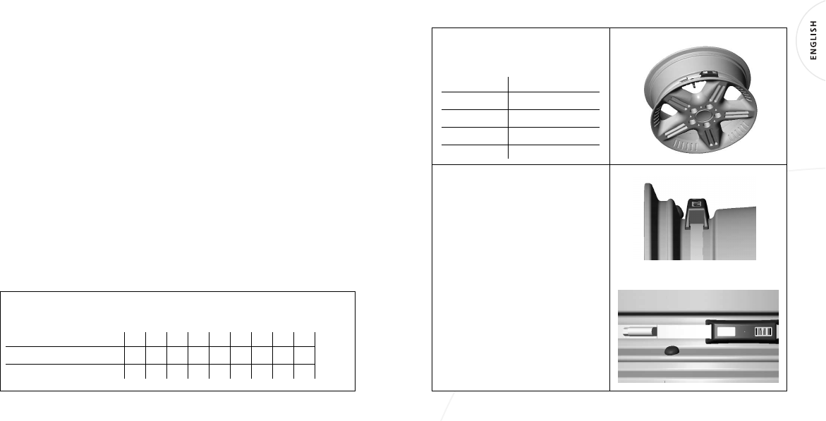
INSTALLING TRANSMITTER ON A WHEEL
Shorten the strap by cutting to the appropriate length for the wheel diameter
used (see chart). Remove burrs from strap end.
Nominal wheel size (inches)
15 16 17 18 19 20 21 22 23
Cut-off length (inches)
28 25 22 19 15 12 9 6 3
Cut-off length (cm)
71 64 56 48 38 30 23 15 8
Below is the suggested installation
sequence for use with optional Full
Function Display.
Transmitter Wheel Position
Green Right front
Red Left front
Blue Right rear
Yellow Left rear
The base of the drop centre well must
be flat and wide enough to allow the
Transmitter to contact the rim over its
complete width.
(see Fig.2)
• Pass strap through Transmitter as shown.
• Position the Transmitter in the lowest
area of the drop centre well near the
valve.
(see Fig.3)
• Attach the strap end to the clamp
by advancing the wormgear with the
socket driver. Tighten to 35 inch
pounds (4 N-m).
• Cut off excess strap length to approxi-
mately one inch (25 mm) from the
wormgear.
FIG.1
FIG.2
FIG.3
1312
SMARTIRE SYSTEMS INC.
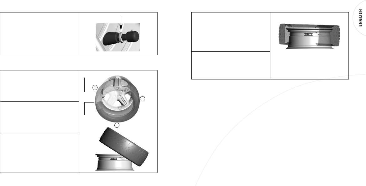
Attach the corresponding color of washer
on the valve stem as shown.
(see Fig.4)
Proceed to mount the tire on the wheel.
Note: Color washer must stay with the
corresponding color Transmitter during
installation and tire rotation.
MOUNTING TIRE WITH TRANSMITTER ON WHEEL
To avoid damaging the Transmitter
during tire mounting, position the
wheel with the Transmitter located at
7 o’clock in relation to the mount head
at 12 o’clock.
Set the lubricated tire on the wheel
with its traction point 3 in. (75 mm)
before the Transmitter. Use the mount
head to guide the rest of the bottom
bead over the flange and onto the rim.
With the bottom bead in place, you will
be able to position the wheel with the
Transmitter at 7 o’clock for most tires.
Depress the bead into the drop centre so
that the traction point is 3 in. (75 mm)
before the Transmitter.
Traction
point
Transmitter
12
7
3
FIG.4
Some stiff side wall tires (such as “run-
flats”) require setting the Transmitter
between 3 o’clock and 6 o’clock. Start
the top bead in front of the mount
head assisting with the mounting bar
to prevent slippage.
Inflate the tire to seat the bead, deflate
completely and then inflate the tire to
manufacturer’s recommended cold
inflation pressure. Balance the wheel.
1514
SMARTIRE SYSTEMS INC.
DE-MOUNTING THE TIRE WITH TRANSMITTER INSTALLED
Remove the tire/wheel assembly from
vehicle and deflate completely.
Loosen both beads with the bead
loosener shoe opposite the valve stem
(away from the Transmitter which is
located near the valve stem). Verify the
Transmitter location.
Orient the wheel to place the Transmitter
3 in. (75 mm) to the left of the bead
guiding shoe so that the mounting bar
will clear the Transmitter. When lifting
the top bead the tire must be clear of
the Transmitter. Remove the top bead.
Set the wheel once more with the
Transmitter 3 in. (75 mm) to the left of
the bead guiding shoe and remove the
bottom bead. The Transmitter should
be checked for correct positioning and
fit prior to tire replacement.
Transmitter
Valve
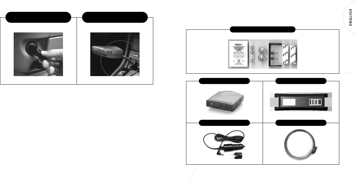
RECEIVER INSTALLATION
The Receiver is installed:
1. By mounting in a convenient location
• With bracket and suction cups to windshield
• With bracket and screws (provided by user)
• With Velcro strips to dash
2. Plug in power
• With power cable
• Using the power adapter (accessory)
R
ECEIVER ATTACHED TO WINDSHIELD
WITH BRACKET AND SUCTION CUPS
R
ECEIVER ATTACHED TO SURFACE
WITH
V
ELCRO
®
STRIPS
1716
SMARTIRE SYSTEMS INC.
R
ECEIVER POWER CABLE PLUG
INSERTED INTO UTILITY PLUG
OPTIONAL POWER ADAPTER
–
MOUNT
R
ECEIVER AS SHOWN
For universal vehicle installations, the Basic Receiver can be plugged into a utility
power outlet or cigarette lighter socket using the supplied power cable. For
permanent connection to vehicle’s power supply, the Basic Receiver can be hardwired
to a keyed power circuit. Only personnel trained in adapting wiring systems should
attempt this installation.
Service and Warranty
COMPONENT PART NUMBERS
200.0059 B
ASIC
R
ECEIVER
200.0100 T
RANSMITTER
(4)
069.0001 I
NSTALLATION
K
IT
069.0002 C
ABLE
K
IT
264.0115 S
TRAP
(4)

1918
SMARTIRE SYSTEMS INC.
TROUBLESHOOTING
Problem Cause and actions
Receiver lights do not turn on No power to Receiver. Check power
connection at receiver end and at utility
plug. Check fuse in power plug. Reseat
connectors if required. Ensure the lead is
not plugged into the diagnostic port.
Tire indicator light stays amber Data not received from Transmitter
location. Relocate Receiver as interference
may be the issue. If problem is not
corrected contact your dealer.
Alert light turns on but air pressure Verify that the alert and wheel color
is normal in tire codes match. Confirm tire inflation
pressure with accurate gauge. Contact
your dealer.
FACTORY DEFAULT SETTINGS
Low Pressure Alert 22 psi 1.53 bar
Low Pressure Warning 18 psi 1.25 bar
TECHNICAL SPECIFICATIONS
Strap Mount Transmitter
Battery Life (Projected) > 5 Years normal vehicle use
Operating temperature range -40° F to 257° F (-40°C to 125° C)
Operating humidity 95% non condensing
Weight 40g (1.41 oz)
Size 3-
1
/
4
” x 1-
1
/
8
” x 1”
(83 mm x 29 mm x 25 mm)
Frequency 433.92 MHz
Pressure Range 0 –78 psi (5.38 bar)
Pressure accuracy +
/
- 1.5 psi (0.1 bar)
Temperature accuracy +
/
-3°C (5°F)
Transmitter activation Vehicle motion greater than
6mph (10 kph)

2120
SMARTIRE SYSTEMS INC.
Basic Receiver
Power Consumption 20 ma. nominal, 125 ma. maximum
during alert
Operating Temperature Range -40° F to 185° F (-40°C to 85° C)
Frequency 433.92 MHz ± 75 KHz
Size 2.85” W x 3.08” D x 0.87” H
(72 mm W x 78 mm D x 22 mm H)
Weight 67 gm (2.4 oz)
Operating Humidity 100% non condensing
US WARRANTY
This Warranty covers substantial manufacturer’s defects in workmanship and
materials. It does not cover any unit that is damaged beyond normal usage, was not
properly installed, was subjected to chemical contact, or other acts or omissions not
sanctioned by the Owner’s Manual.
All components are covered for one (1) year and unlimited mileage following the
date of purchase.
The SmarTire
®
Warranty will be honored by any authorized SmarTire
®
dealer. The
owner is required to provide dated proof of purchase. The authorized dealer will
determine if there is a warrantable condition associated with materials and/or
manufacturing workmanship. If a warrantable condition exists, the component
will be replaced free of charge, shipping prepaid. The owner is responsible for any
labor and installation charges.
Telephone 604-276-9884 to obtain a Return Material Authorization (RMA) number.
Send the postage prepaid package with the defective unit and RMA number to:
SmarTire USA Inc., PMB 309, 1700 W. Market Street, Akron, Ohio, USA, 44313.
The Warranty does not include any further obligation whatsoever, including but not
limited to actual installation of the replacement unit on the customer’s vehicle.
All other Warranties, express or implied, are disclaimed. All collateral agreements,
which purport to modify this Limited Warranty are of no effect. The absolute limit
of liability is the purchase price of the unit. SmarTire Systems Inc. is not liable for
any direct, consequential, indirect or punitive damages of any kind.
SOME STATES DO NOT ALLOW LIMITATIONS ON THE VALIDITY OR LENGTH OF IMPLIED
WARRANTIES, SO THE ABOVE LIMITATIONS MAY NOT APPLY TO YOU.
SOME STATES DO NOT ALLOW THE EXCLUSION OR LIMITATION OF INCIDENTAL OR CONSE-
QUENTIAL DAMAGES, SO THE ABOVE LIMITATION OR EXCLUSION MAY NOT APPLY TO YOU.
THIS WARRANTY GIVES YOU SPECIFIC LEGAL RIGHTS, AND YOU MAY HAVE OTHER
RIGHTS WHICH VARY FROM STATE TO STATE.

2322
SMARTIRE SYSTEMS INC.
CANADIAN WARRANTY
This Warranty covers substantial manufacturer’s defects in workmanship and
materials. It does not cover any unit that is damaged beyond normal usage, was not
properly installed, was subjected to chemical contact, or other acts or omissions not
sanctioned by the Owner’s Manual.
All components are covered for one (1) year and unlimited mileage following the
date of purchase.
The SmarTire
®
Warranty will be honoured by any authorized SmarTire
®
dealer.
The owner is required to provide dated proof of purchase. The authorized dealer
will determine if there is a warrantable condition associated with materials and/or
manufacturing workmanship. If a warrantable condition exists, the component
will be replaced free of charge, shipping prepaid, if within the applicable warranty
period. The owner is responsible for any labour and installation charges.
Telephone 604-276-9884 to obtain a Return Material Authorization (RMA) number.
Send the postage prepaid package with the defective unit and RMA number to:
SmarTire Systems Inc., 13151 Vanier Place, Suite 150, Richmond, British Columbia,
Canada, V6V 2J1.
The Warranty does not include any further obligation whatsoever, including but not
limited to actual installation of the replacement unit on the customer’s vehicle.
ALL OTHER WARRANTIES AND CONDITIONS, EXPRESS OR IMPLIED, INCLUDING
WARRANTIES AND CONDITIONS FOR MERCHANTABILITY, DURABILITY OR FITNESS FOR
PURPOSE, ARE DISCLAIMED. ALL COLLATERAL AGREEMENTS, WHICH MODIFY THIS SOLE
WARRANTY ARE OF NO EFFECT. SMARTIRE SYSTEMS INC. IS NOT LIABLE FOR ANY DIRECT,
CONSEQUENTIAL, INDIRECT OR PUNITIVE DAMAGES. THE ABSOLUTE LIMIT TO LIABILITY
IS THE PURCHASE PRICE OF THE UNIT.
EUROPEAN WARRANTY
SmarTire Europe Limited (“SmarTire”) hereby warrants that this SmarTire wireless
tyre pressure monitoring system shall be free from material defects in workmanship
and/or materials until the expiry of 24 months from its purchase by the end user
and unlimited mileage, EXCEPT WHERE any such defect has been caused by:
1. Improper installation;
2. Improper or non-normal use;
3. Contact with any corrosive or otherwise harmful substance; or
4. Any other act or omission not sanctioned by the Owner’s Manual or any failure
to follow any other reasonable instructions given by SmarTire in relation to the
system.
The above warranty will be honoured by the retailer from which it was purchased,
provided that the owner can provide dated proof of purchase.
The retailer shall at their own cost return any unit suspected to be defective. If the
unit is subsequently found to be defective then the carriage costs shall be refunded
in full. Send the postage prepaid package with the defective unit to: SmarTire, Park
34, Didcot, Oxfordshire OX11 7WB, England.
In the event that any defect in the unit is covered by the above warranty, SmarTire
will replace the affected components free of charge, shipping prepaid. The owner
shall be responsible for any labour and installation costs incurred in removing the
defective parts and/or installing the replacements.
SAVE AS SET OUT HEREIN SMARTIRE SHALL HAVE NO FURTHER LIABILITY OR
OBLIGATION UNDER THE ABOVE WARRANTY. THIS WARRANTY SHALL BE GOVERNED
AND CONSTRUED IN ACCORDANCE WITH ENGLISH LAW.
YOUR STATUTORY RIGHTS ARE NOT AFFECTED.
2524
SMARTIRE SYSTEMS INC.
Appendix
GLOSSARY
Cold Pressure The vehicle manufacturers recommended inflation
pressure of a tire at ambient temperature (64° F or 18°C).
Low Pressure Alert The audible and visual alert activated when the tire’s
Actual Pressure drops to the programmed value.
Low Pressure Warning The audible and visual alert activated when the tire’s
Actual Pressure drops to the programmed value. This value
is lower than the Low Pressure Alert.
Receiver The electronic module that receives data from the
Transmitter and displays tire pressure alerts.
Transmitter The wheel mounted electronic module that measures
contained air pressure and transmits this data to the
Receiver.
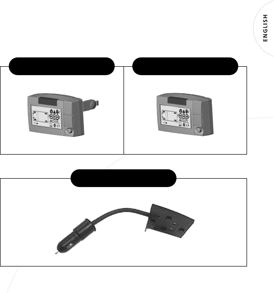
OPTIONAL COMPONENTS
Full Function Display
(two versions)
See Full Function Display manual for details on installation and operation.
K
IT
N
UMBER
061.3000
P
OWER
A
DAPTER
K
IT
N
UMBER
061.4000
F
ULL
F
UNCTION
D
ISPLAY
K
IT
N
UMBER
061.4001
F
ULL
F
UNCTION
R
EMOTE
D
ISPLAY