Bendix Bw2907 Users Manual
2015-03-12
: Bendix Bendix-Bw2907-Users-Manual-651497 bendix-bw2907-users-manual-651497 bendix pdf
Open the PDF directly: View PDF ![]() .
.
Page Count: 64
1
Bendix® Wingman® Advanced™ (FLR20™ Sensor)
SD-61-4960
DESCRIPTION
The Bendix® Wingman® Advanced™ system is an integrated
combination of three features:
• Adaptive cruise control with braking;
• Alerts (several different types); and
• Collision mitigation technology.
PART ONE: ADAPTIVE CRUISE
CONTROL WITH BRAKING
The adaptive cruise control with braking feature is an
additional upgrade of ordinary cruise control. When using
cruise control, the Wingman Advanced system will maintain
the set speed, and also will intervene, as needed, to help
maintain a set following distance behind a detected forward
vehicle.
Using a radar sensor mounted to the front of the vehicle
— with a range of approximately 500 feet — the Wingman
Advanced system reacts to detected forward vehicles in the
same lane, traveling in the same direction. See Figure 1.
The adaptive cruise control with braking feature is designed
to help the driver maintain a set following distance between
his vehicle and a detected forward vehicle when cruise
control is set. See the gray "Radar Beam" area in Figure 2.
Once cruise control is set and the system is maintaining a
set following distance between you and the vehicle in front:
WARNING
Improper use of the Bendix® Wingman® Advanced™
system can result in a collision causing property
damage, serious injuries, or death.
The driver is always responsible for the control and
safe operation of the vehicle at all times. The Bendix
Wingman Advanced system does not replace the
need for a skilled, alert professional driver, reacting
appropriately and in a timely manner, and using safe
driving practices.
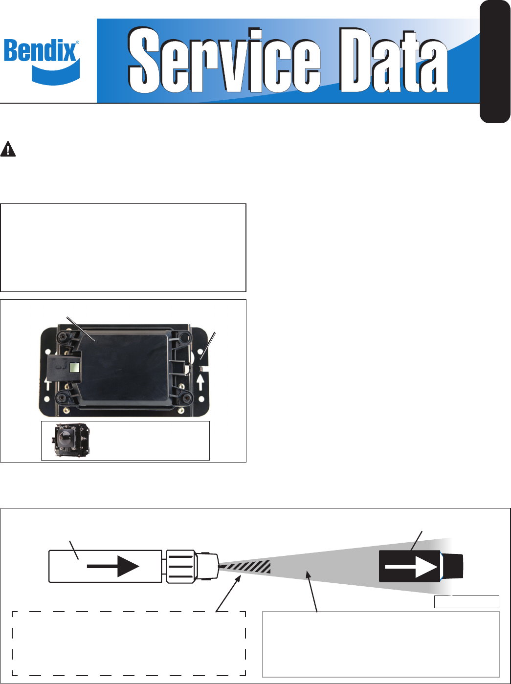
FIGURE 1 - BENDIX® WINGMAN® FLR20™ RADAR SENSOR
AND COVER
FIGURE 2 - BENDIX® WINGMAN® ADVANCED™ SYSTEM RADAR DETECTION
NOT TO SCALE
Detected Forward Vehicle
RADAR BEAM
Vehicle Equipped with Bendix®
Wingman® Advanced™
The GRAY area approximates the zone where the
Wingman Advanced system – when cruise control
is set – is ready to intervene with up to one-third
of the vehicle’s braking capacity, if needed.
The STRIPED area approximates the zone
where the collision mitigation feature is ready to
intervene with up to two-thirds of the vehicle’s
braking capacity, if needed, as long as the
vehicle is traveling above 15 mph.
FOR THE BENDIX® WINGMAN®
FLR10™ RADAR SENSOR
SEE SD-61-4962
RADAR SENSOR MOUNTING
BRACKET
(VARIES)

2
If the vehicle in front of you slows down below the cruise
control’s set speed, the Bendix® Wingman® Advanced™
system will intervene and, as necessary, in this order:
(a) reduce the engine throttle; then
(b) apply the engine retarder; then
(c) apply the foundation brakes,
in an attempt to maintain the set following distance behind
the vehicle ahead. NOTE: If during the intervention, it is
necessary to apply the foundation brakes, the vehicle will
not automatically resume the cruise control set speed.
If the vehicle ahead slows below the cruise control’s set
speed, but then accelerates away, and the Wingman
Advanced system did not need to use the foundation
brakes, the system will automatically accelerate back to the
original cruise control set speed, and again maintain a set
following distance behind any detected forward vehicles.
Because the Wingman Advanced system operates along
with normal cruise control, all the typical features built
into cruise control work as usual. For example, limits
imposed by factory-set road speed governors, etc. are fully
supported by the Wingman Advanced system.
PART TWO: ALERTS
Bendix Wingman Advanced also assists by giving audible
and visual alerts, whether or not cruise control is on. See
Pages 8-10 for more information on the three types of alerts
the driver may hear and/or see displayed.
PART THREE: COLLISION
MITIGATION TECHNOLOGY
See the striped area in Figure 2. The Wingman Advanced
collision mitigation technology is designed to be ready to
react to the presence of moving vehicles in front of your
vehicle (whether or not cruise control is set). Collision
mitigation interventions can be up to two-thirds of the
vehicle’s braking capacity. The system provides the driver
with an alert before an intervention occurs. The driver must
immediately act to potentially avoid, or lessen the severity
of, a collision.
GENERAL SAFETY GUIDELINES
WARNING! PLEASE READ AND FOLLOW THESE INSTRUCTIONS
TO AVOID PERSONAL INJURY OR DEATH:
When working on or around a vehicle, the following guidelines should be observed AT ALL TIMES:
▲ Park the vehicle on a level surface, apply the
parking brakes and always block the wheels.
Always wear personal protection equipment.
▲Stop the engine and remove the ignition key
when working under or around the vehicle.
When working in the engine compartment,
the engine should be shut off and the ignition
key should be removed. Where circumstances
require that the engine be in operation, EXTREME
CAUTION should be used to prevent personal
injury resulting from contact with moving,
rotating, leaking, heated or electrically-charged
components.
▲Do not attempt to install, remove, disassemble
or assemble a component until you have read,
and thoroughly understand, the recommended
procedures. Use only the proper tools and
observe all precautions pertaining to use of those
tools.
▲If the work is being performed on the vehicle’s
air brake system, or any auxiliary pressurized air
systems, make certain to drain the air pressure
from all reservoirs before beginning ANY work
on the vehicle. If the vehicle is equipped with a
Bendix® AD-IS® air dryer system, a Bendix® DRM™
dryer reservoir module, or a Bendix® AD-9si™ air
dryer, be sure to drain the purge reservoir.
▲ Following the vehicle manufacturer’s
recommended procedures, deactivate the
electrical system in a manner that safely removes
all electrical power from the vehicle.
▲Never exceed manufacturer’s recommended
pressures.
▲Never connect or disconnect a hose or line
containing pressure; it may whip. Never remove
a component or plug unless you are certain all
system pressure has been depleted.
▲ Use only genuine Bendix® brand replacement
parts, components and kits. Replacement
hardware, tubing, hose, ttings, etc. must be of
equivalent size, type and strength as original
equipment and be designed speci cally for such
applications and systems.
▲Components with stripped threads or damaged
parts should be replaced rather than repaired.
Do not attempt repairs requiring machining or
welding unless speci cally stated and approved
by the vehicle and component manufacturer.
▲Prior to returning the vehicle to service, make
certain all components and systems are restored
to their proper operating condition.
▲ For vehicles with Automatic Traction Control
(ATC), the ATC function must be disabled (ATC
indicator lamp should be ON) prior to performing
any vehicle maintenance where one or more
wheels on a drive axle are lifted off the ground
and moving.
▲The power MUST be temporarily disconnected
from the radar sensor whenever any tests USING
A DYNAMOMETER are conducted on a Bendix®
Wingman® Advanced™-equipped vehicle.
▲ You should consult the vehicle manufacturer's operating and service manuals, and any related literature,
in conjunction with the Guidelines above.
3
KEY CONTENTS
(See the full index on pages 60-59)
1.0 Operation .................................. 3-10
1.4 What to Expect When Using the Bendix
Wingman Advanced System ..................... 5-6
1.5 How the Driver Interacts
with Bendix Wingman Advanced ....................7
1.8 Alerts and Warnings .......................... 8-10
2.0 Maintenance ............................... 11-12
3.0 Introduction to Troubleshooting ................. 13-16
3.2 Narrowing Down the Problem (Table 3.2) ......... 14-15
4.0 Troubleshooting/Diagnostics .................. 17-27
4.1 Bendix® ACom® Diagnostics Software ..............17
4.3 Diagnostic Trouble Codes (DTCs) .............. 19-25
5.0 Other System Features ....................... 28-31
Appendices A - H ................................ 32-59
1.0 OPERATION SECTION
Section Index
1.1 Important Safety Information/
When Not to Use Bendix® Wingman® Advanced™
Adaptive Cruise Control with Braking . . . . . 3
1.2 System Components. . . . . . . . . . . . . . 4
1.3 Activating the Bendix Wingman
Advanced System . . . . . . . . . . . . . . . 4
1.4 What to Expect When Using The
Wingman Advanced System . . . . . . . . . 5-6
1.5 How a Driver Interacts with the
Wingman Advanced System . . . . . . . . . . 7
1.6 Following Distance . . . . . . . . . . . . . . . 8
1.7 Wingman Advanced Collision Mitigation
Feature Operation . . . . . . . . . . . . . . . 8
1.8 Alerts and Warnings . . . . . . . . . . . . . 8-10
1.9 Wingman Advanced Diagnostic
Trouble Codes . . . . . . . . . . . . . . . . .10
1.10 Radar Sensor Interchangeability. . . . . . . .10
1.11 Alert Volume . . . . . . . . . . . . . . . . . . 10
1.12 Potential False Warnings . . . . . . . . . . . 10
1.1 IMPORTANT SAFETY INFORMATION
The driver is always responsible for the control and
safe operation of the vehicle at all times. The Bendix
Wingman Advanced system does not replace the
need for a skilled, alert professional driver, reacting
appropriately and in a timely manner, and using safe
driving practices.
This vehicle's cruise control must be used only in the same
conditions that are normally recommended for ordinary
cruise control.
Vehicle manufacturers may use alerts, messages, and
dash arrangements that vary from the examples shown
here. Consult the vehicle operator’s manual for applicable
details regarding use and operation.
WHEN NOT TO USE BENDIX WINGMAN
ADVANCED ADAPTIVE CRUISE
CONTROL WITH BRAKING
The adaptive cruise control with braking feature in
Wingman Advanced is automatically ready when
normal cruise control is set.
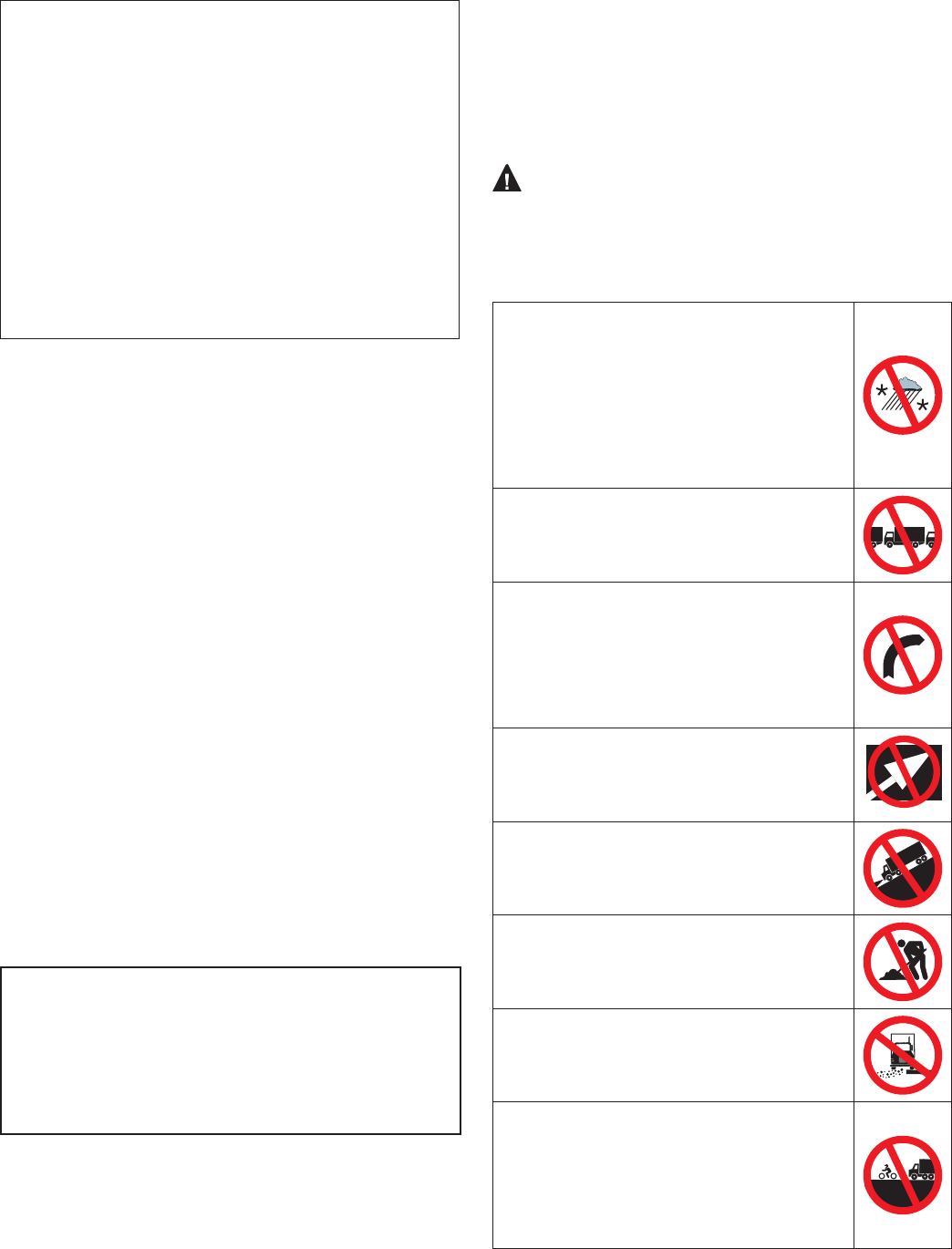
WARNING: This vehicle’s cruise control must be
used only in the same conditions that are normally
recommended for ordinary cruise control. As noted
below, there are certain situations when cruise control
should NOT be used.
• Inclement Weather/Low Visibility
Situations – Do not use cruise control
in inclement weather or low visibility
conditions such as rain, snow, smoke, fog,
ice or other severe weather conditions
that may affect the performance of the
Wingman Advanced system.
• Dense Trafc – Do not use cruise control
in heavy trafc.
• Sharp Curves and Winding Roads –
Do not use cruise control when traveling
sharply curved or winding roadways.
CAUTION: Road curvature may impact
the radar’s ability to track vehicles ahead
in the same lane.
• Entrance or Exit Ramps – Do not use
cruise control when entering or exiting
roadways.
• Downhill Grades – Do not use cruise
control on downhill grades.
• Construction Zones – Do not use cruise
control in construction zones.
• Off-Road – Do not use cruise control in
off-road conditions.
• Smaller Forward Vehicles – Smaller
vehicles, such as motorcycles, may be
difcult for the radar to identify. It is the
driver’s responsibility to be aware of
these types of vehicles and to slow down
if necessary.
Visit www.bendix.com for more information along with any updates
to these limitations and restrictions.
4
AUTOMATIC FOUNDATION
BRAKE APPLICATIONS
The vehicle automatically manages foundation brake
priorities among the various vehicle systems that use the
foundation brakes, such as Bendix® Wingman® Advanced™
system, Bendix® ESP® Electronic Stability Program,
Bendix® ATC (Automatic Traction Control) and Bendix®
ABS (Antilock Braking System).
NOTE: Cruise control will automatically cancel whenever
the Wingman Advanced system applies the foundation
brakes. You can verify that your cruise control is disengaged
by observing that the cruise-enabled icon is no longer
illuminated. You must resume or set cruise control in
order to regain normal cruise control functionality and to
reengage the adaptive cruise control with braking feature
of the Wingman Advanced system.
Additional information, and complete troubleshooting
procedures for the Bendix ESP stability system, can be
found in the Bendix Service Data Sheet SD-13-4869.
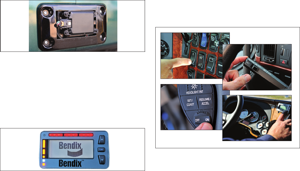
1.2 SYSTEM COMPONENTS
The radar sensor (or radar) used in the Wingman Advanced
unit is located at the front of the vehicle – either on the
bumper or just behind it on a cross-member. See Figure 3.
FIGURE 3 - COMPONENT: RADAR SENSOR
The radar sensor is pre-aligned at the factory and no
adjustment should be needed. If the radar sensor becomes
misaligned (or a diagnostic trouble code is issued), either a
message – or light on the dash, depending on the vehicle –
lets the driver know that service is needed.
The Wingman Advanced system is either fully integrated
into the vehicle dashboard, or uses the Bendix® Driver
Interface Unit (DIU). See Figure 4.
FIGURE 4 - BENDIX DRIVER INTERFACE UNIT (DIU)
Although the system functions the same, how the alerts
are displayed to the driver can be different. Where a DIU
(Driver Interface Unit) is used, all visual, text, and audible
indicators and alerts will be provided by the DIU. The DIU
allows the volume to be adjusted. See Appendix F.
Also see the Alerts and Warnings section of this manual
for more detailed information about the alerts.
NOTE: For some integrated systems, the volume level of
the alerts is not adjustable, nor can they be switched off.
1.3 ACTIVATING THE BENDIX®
WINGMAN® ADVANCED™ SYSTEM
To have the Wingman Advanced cruise control with braking
features of the Wingman Advanced system (engine de-
throttle/retard, foundation brake interventions) the vehicle’s
regular cruise control must be switched on. See Figure 5
for examples of switches that may be used.
When the vehicle reaches the desired cruise speed, the
driver presses the cruise control set switch to activate the
system. The Wingman Advanced system will then engage
and help the driver maintain a set following distance behind
the vehicle traveling in front.
Once the cruise control speed is set, a cruise-enabled icon
(or similar) will illuminate on the instrument panel. If the
cruise-enabled or set (or similar) icon does not illuminate,
the Wingman Advanced system is not functioning normally.
Refer to the vehicle operator’s manual to double-check
the location of the icon, and for further troubleshooting
information.
The driver can switch off the Wingman Advanced system
manually by either stepping on the brake pedal or switching
off the cruise control.
FIGURE 5 - EXAMPLES OF CRUISE CONTROL SWITCHES
IMPORTANT NOTE: Cruise control will automatically
cancel whenever Wingman Advanced applies the
foundation brakes.

5
1.4 WHAT TO EXPECT WHEN USING THE BENDIX® WINGMAN® ADVANCED™ SYSTEM
Table 1, parts 1-3, illustrate what to expect from the Wingman Advanced system in various driving situations. Typical
system indications and actions to expect from the system are illustrated.
What to Expect (1.4)
Part One: All driving scenarios (Cruise is either “on” or “off”)
Situation Typical System
Indication/Alerts Typical System Actions
A broken-down vehicle is
stationary in the lane in which
the truck is traveling.
A Stationary Object Alert may be
issued up to 3 (three) seconds
prior to impact.
None.
A pedestrian, deer or dog runs in
front of the truck.
None. None.
Another vehicle crosses the
road perpendicular to your
path of travel – such as at an
intersection.
None. None.
TABLE 1 - PART 1 - OPERATIONAL SCENARIOS WITH THE WINGMAN ADVANCED SYSTEM
What to Expect (1.4)
Part Two: Cruise control “on” and speed “set”
Situation Typical System
Indication/Alerts Typical System Actions
With no detected forward
vehicle.
None. Vehicle maintains set speed.
With a detected forward
vehicle.
The cruise control ON indicator
is illuminated and the detected
forward vehicle icon is
illuminated.
The adaptive cruise control with braking feature
will maintain the set speed and following
distance.
The detected forward vehicle
slows moderately.
The Following Distance Alert
(FDA) will sound and a visual
message/icon typically appears
on the dash screen or Bendix®
Driver Interface Unit (DIU)
display.
The vehicle will be slowed by (a) reducing
throttle; (b) then engaging the engine retarder;
and (c) then applying the foundation brakes.
Note: If the foundation brakes are applied,
cruise control is cancelled.
The detected forward vehicle
slows rapidly.
The Impact Alert (IA) warning
(continuous tone), will sound and
a visual message/icon typically
appears on the dash screen
or DIU display. The Following
Distance Alert may also be heard.
The vehicle throttle will be reduced; the engine
retarder engaged; and the foundation brakes
applied, in that order.
The cruise control feature cancels after the
event.
The detected forward vehicle
cuts in front of the truck but
then speeds away.
Following Distance Alerts may be
given to the driver, depending on
the exact system conguration
that has been set for the vehicle,
and how close the vehicle cuts in
front.
Vehicle maintains set speed.
NOTE: The system indicators/alerts above are typical, but may vary from the descriptions shown here by vehicle
manufacturer, or earlier versions of the Wingman Advanced system.

6
What to Expect (1.4)
Part Two: Cruise control “on” and speed “set”
Situation Typical System
Indication/Alerts Typical System Actions
Going down a grade with a
detected forward vehicle.
Cruise control should NOT be
used on downhill grades - see
page 3.
(See the CDL manual
instructions on proper gear
usage for downhill grades.)
DO NOT USE cruise control on
downhill grades.
DO NOT USE cruise control on downhill
grades.
TABLE 1 - PART 2 - OPERATIONAL SCENARIOS WITH THE BENDIX® WINGMAN® ADVANCED™ SYSTEM
NOTE: The system indicators/alerts above are typical, but may vary from the descriptions shown here by vehicle
manufacturer, or earlier versions of the Wingman Advanced system.
What to Expect (1.4)
Part Three: Cruise control NOT “SET”, or “OFF”
Situation Typical System
Indication/Alerts Typical System Actions
Your vehicle comes up
fast behind a slower-
moving detected forward
vehicle.
The Following Distance Alert (FDA) will sound and a
visual message/icon typically appears on the dash
screen or DIU display. Depending on how close your
vehicle approaches, the system may initiate an Impact
Alert warning.
If a collision is likely to occur,
the collision mitigation feature
will apply up to two-thirds of
the vehicle’s braking capacity.
The driver must
immediately act to
potentially avoid, or lessen
the severity of, a collision.
The detected forward
vehicle slows rapidly.
The Following Distance Alert (FDA), or Impact Alert
warning (continuous tone) will sound and a visual
message/icon typically appears on the dash screen or
DIU display.
If a collision is likely to occur,
the collision mitigation feature
will apply up to two-thirds of
the vehicle’s braking capacity.
The driver must
immediately act to
potentially avoid, or lessen
the severity of, a collision.
TABLE 1 - PART 3 - OPERATIONAL SCENARIOS WITH THE BENDIX® WINGMAN® ADVANCED™ SYSTEM
NOTE: These are typical situations and responses that may occur when using the Wingman Advanced system. All
possible situations and responses are not covered in this table.
Due to inherent limitations of radar technology, the collision mitigation technology — on rare occasions — may not
detect moving vehicles or stationary objects in your vehicle’s lane of travel. Alerts, warnings or brake interventions
may not occur.
Due to inherent limitations of radar technology, the collision mitigation technology — on rare occasions — may react
to moving vehicles not in your vehicle’s lane of travel. Alerts, warnings or brake interventions may occur.

7
1.5 HOW A DRIVER INTERACTS WITH THE BENDIX® WINGMAN® ADVANCED™ SYSTEM
Table 2 illustrates how the Wingman® Advanced™ system will respond to various actions a driver may take when using
Wingman Advanced system on the road.
The driver is always responsible for the control and safe
operation of the vehicle at all times. The Bendix® Wingman®
Advanced™ system does not replace the need for a skilled,
alert professional driver, reacting appropriately and in a
timely manner, and using safe driving practices.
How a Driver Interacts with Bendix® Wingman® Advanced™ (1.5)
Action Reaction of Wingman Advanced
If the driver does this: Expect the Wingman Advanced system to do this:
Steps on the brake.
(During a collision
mitigation event.)
The driver is always in control and is able to apply full braking power.
Steps aggressively on the
accelerator. (During a
collision mitigation event.)
The driver is always in control. His/her actions override any Wingman Advanced
system actions. Note: If cruise control is engaged, it will be overridden until the
accelerator is released; then cruise control will resume the original set speed
automatically.
Steps on the brake. (When
in cruise.) Cruise control will be cancelled.
Steps on the accelerator.
(When in cruise.)
Cruise control will be overridden until the accelerator is released; then cruise control
will resume the original set speed automatically.
Switches on the cruise
control.
Nothing. The adaptive cruise control with braking feature will not engage until the
driver sets the cruise control speed.
Switches off the cruise
control.
The adaptive cruise control with braking feature will turn off; the collision mitigation
feature remains active and ready to intervene. The driver will continue to hear all
alerts as needed.
Sets the cruise control
speed.
The adaptive cruise control with braking feature is automatically activated. Your
vehicle maintains a set speed and following distance behind the vehicle ahead.
Covers or blocks the radar.
The Wingman Advanced system performance will be diminished or even disabled
and a Diagnostic Trouble Code (DTC) will be set. A blockage will also affect engine
cruise control availability.
Uses normal cruise control
“+/-” switch.
Vehicle speed increased (+) or reduced (-) to achieve the new set speed while
actively maintaining following distance with the vehicle ahead, if one is present within
500 feet.
TABLE 2 - HOW A DRIVER INTERACTS WITH BENDIX® WINGMAN® ADVANCED™
NOTE: The system responses above are typical, but may vary from the descriptions shown here by vehicle manufacturer,
or earlier versions of the Wingman Advanced system. These are examples of driver actions and typical Wingman
Advanced system responses, however this chart does not attempt to cover all possible situations.
8
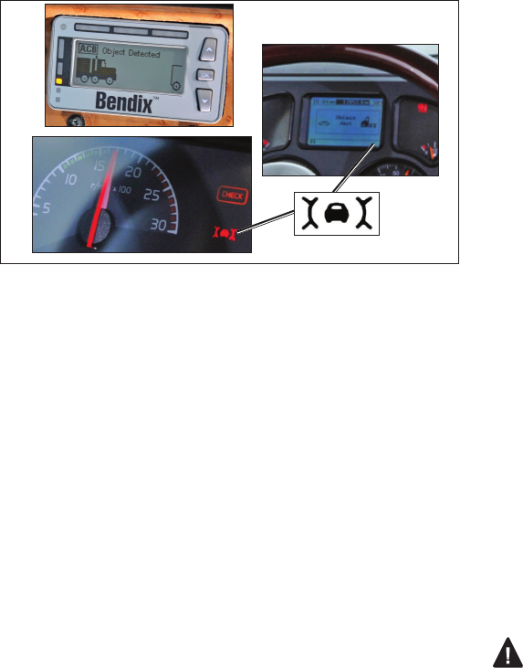
THE FORWARD VEHICLE DETECTED ICON
When cruise control is switched on and set and a vehicle
ahead of you is detected by the radar, the detected forward
vehicle icon — or similar — will illuminate on the vehicle
dashboard.
This is an indication to the driver that the Bendix® Wingman®
Advanced™ system is actively managing the distance
between your vehicle and the vehicle ahead, and may
intervene automatically, if needed.
See Figure 6 for examples.
FIGURE 6 - FORWARD VEHICLE DETECTED ICONS
ADJUSTING THE CRUISE CONTROL SPEED
Use the switch(es) provided by the vehicle manufacturer
to set your cruise control speed. When adjusted, your
set speed will typically be indicated on the vehicle dash,
message center, or speedometer.
1.6 FOLLOWING DISTANCE
Following distance refers to the time gap, measured in
seconds, between your vehicle and the vehicle ahead. The
actual physical distance between the two will vary based
on the speeds of both vehicles; however, the set gap will
remain the same for all set cruise speeds.
FOLLOWING DISTANCE
ADJUSTMENT SWITCH
This optional Wingman® Advanced™ feature, allows the
driver to adjust the following distance or time gap. The
availability of this feature is determined by the vehicle
manufacturer. The switch has an increase or decrease
function. Pressing increase (+) will provide a larger
following distance, measured in seconds. Pressing
decrease (-) will provide a shorter following distance.
1.7 WINGMAN ADVANCED COLLISION
MITIGATION FEATURE OPERATION
Whenever your vehicle is traveling at above 15 mph, the
Wingman Advanced collision mitigation feature is ready to
intervene, if needed. It does not require cruise control to be
set. The collision mitigation feature of Wingman Advanced
will alert you automatically and apply up to two-thirds of the
vehicle’s braking capacity, if a collision with the detected
forward vehicle is likely to occur. You, the driver, must
immediately act to potentially avoid, or lessen the severity
of, a collision.
Collision mitigation is ready to intervene as long as no DTCs
are active in either the brake system, Wingman Advanced
system, or any other contributing vehicle system.
AUTOMATIC FOUNDATION
BRAKE APPLICATIONS
The vehicle automatically manages foundation braking
priorities among the various vehicle systems that use
the foundation brakes, such as Wingman Advanced,
Bendix® ESP® (Electronic Stability Program), Bendix®ATC
(Automatic Traction Control) and the Bendix® ABS (Antilock
Braking System).
1.8 ALERTS AND WARNINGS
The Bendix Wingman Advanced system operates differently
compared to other cruise control/forward collision warning
systems. It is important for YOU to fully understand the
system’s features, especially the driver alerts and warnings.
Three important warnings provided by the Wingman
Advanced system are the Following Distance Alert (FDA),
Impact Alert (IA), and Stationary Object Alert (SOA). The
driver will be alerted by any of the three warnings, whether
or not the cruise control is activated.
See Appendix F, Sections 3.0-5.0, for more information
about how DIUs communicate alerts.
WARNING: Any audible and/or visual alert by the
system means that your vehicle is too close to the
vehicle ahead and the driver must immediately act to
potentially avoid, or lessen the severity of, a collision.
9
IMPACT ALERT (IA)
The Impact Alert is the most severe warning issued
by the Bendix® Wingman® Advanced™ system. This
alert indicates that a collision with the detected forward
vehicle is likely and the driver must immediately act to
potentially avoid, or lessen the severity of, a collision.
The Impact Alert is ready to alert the driver whenever
the vehicle is moving above 15 mph.
When activated, the IA will sound and a visual message/
icon typically appears on the dash screen or Bendix® Driver
Interface Unit (DIU) display. The actual sound/display
method varies by vehicle manufacturer.
NOTE: The Impact Alert is typically accompanied by
automatic brake interventions. The Wingman Advanced
system will apply up to two-thirds of your vehicle’s braking
capacity. The driver must apply additional braking, when
necessary, to maintain a safe distance from the vehicle
ahead.
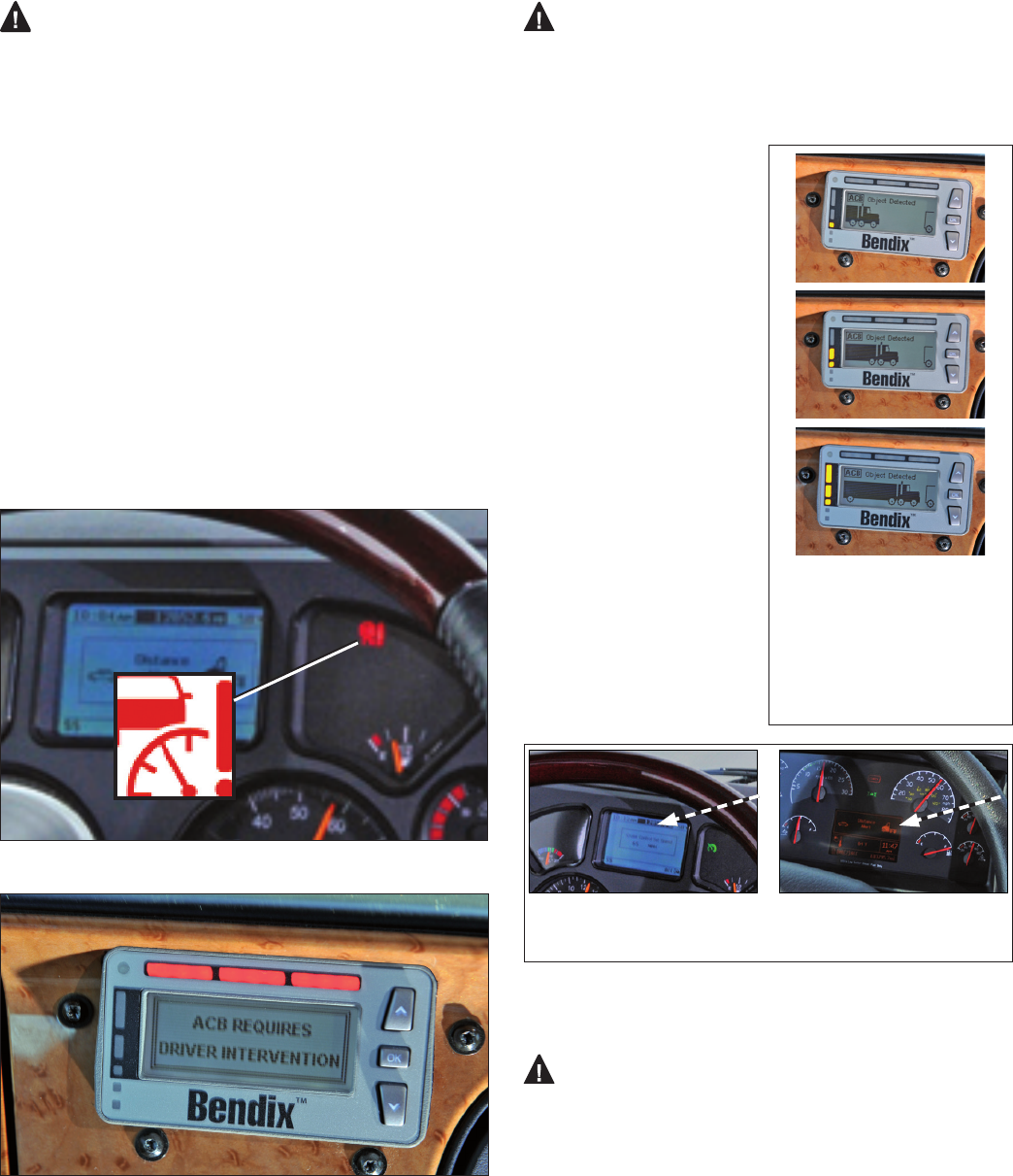
See Figure 7 for an example of an Impact Alert Icon.
FIGURE 7 - EXAMPLE OF IMPACT ALERT ICON
FIGURE 8 - IMPACT ALERT TEXT AND LIGHT PATTERN AS
SEEN ON THE BENDIX® DIU
FOLLOWING DISTANCE ALERT (FDA)
The Following Distance Alert (FDA) provides both
audible and visual alerts whenever the time between
your vehicle and the detected forward vehicle ahead is
less than one and a half (1.5) seconds* and decreasing.
Once the audible alert is given, the driver should
increase the distance
between his/her vehicle
and the vehicle ahead
until the audible alert
stops.
The FDA is ready to alert
the driver whenever the
vehicle is moving above
ve (5) mph. If the following
distance continues to
decrease, the driver will hear
more rapid audible alerts.
When the FDA reaches its
highest level, typically a red
LED also illuminates on the
instrument cluster. The FDA
may be accompanied by a
visual alert.
* 1.5 seconds is the system
default and may vary by
eet/OEM.
Above: Examples of other vehicle
manufacturer’s displays.
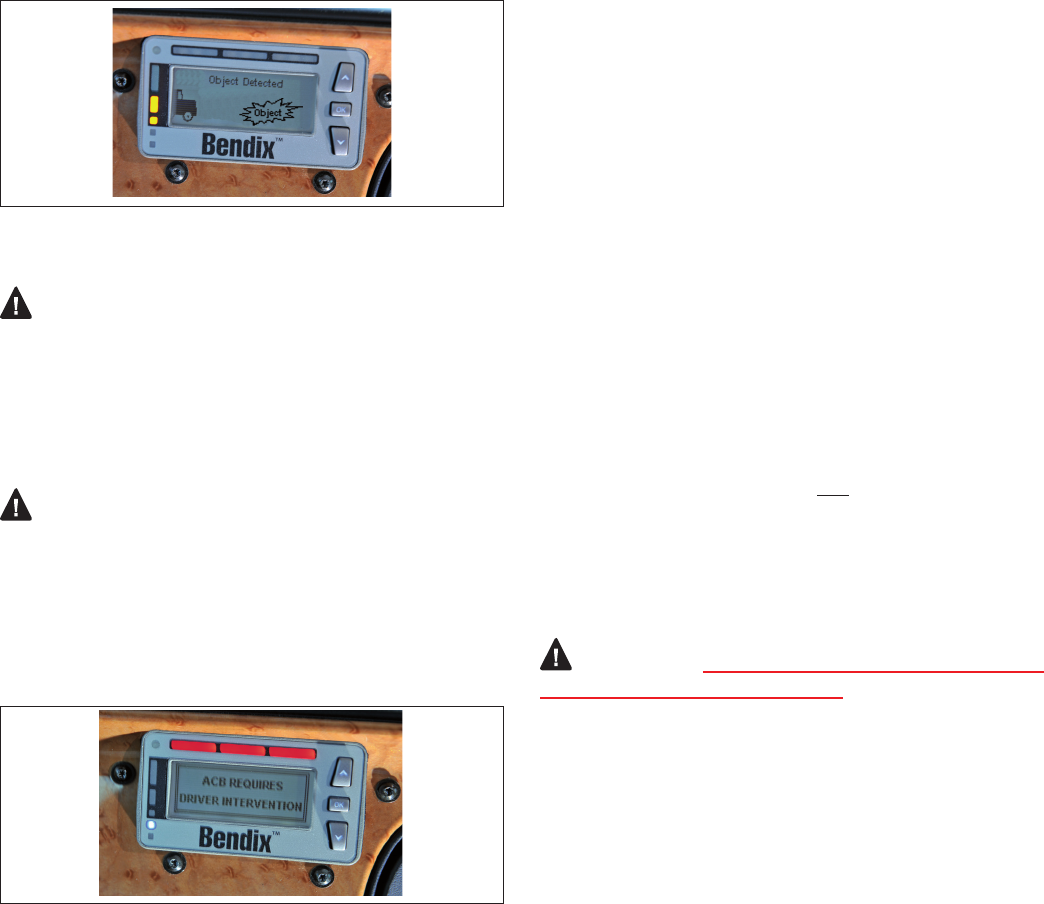
FIGURE 10 - FOLLOWING DISTANCE ALERT
STATIONARY OBJECT ALERT (SOA)
Stationary Object Alert (SOA) – The Bendix®
Wingman® Advanced™ system will give up to a three (3)
second alert to the driver when approaching a detected,
sizable, metallic (radar-reective), stationary object in
your lane of travel. This alert indicates that a collision
with a stationary object is likely and the driver must
immediately act to potentially avoid, or lessen the
severity of, a collision.
The SOA is ready to alert the driver whenever the vehicle
is moving above ten (10) mph.
FIGURE 9 - DRIVER
INTERFACE UNIT (DIU)
SHOWING EXAMPLES
OF FOLLOWING
DISTANCE ALERTS WITH
PROGRESSIVELY FASTER
AUDIBLE ALERTS.
10
The driver should be especially careful when approaching
certain types of vehicles or objects. The Wingman Advanced
radar may not be able to detect vehicles and objects with
limited metal surfaces (such as recreational vehicles,
horse-drawn buggies, motorcycles, logging trailers, etc.).
NOTE: Entering a curve may reduce the alert time to less
than three (3) seconds.
FIGURE 11 - STATIONARY OBJECT ALERT DISPLAYED
BRAKE OVERUSE ALERT
The Bendix® Wingman® Advanced™ system provides
a warning when the system is intervening and using
the foundation brakes excessively. Overuse of the
foundation brakes can lead to the brakes overheating
and a potential loss of braking performance caused
by brake fade. Using cruise control on downhill runs will
cause this alert to be activated.
Approach grades as you would normally, with the
appropriate gear selected and at a safe speed. Cruise
control should NOT be used on downhill grades.
When the system detects brake overuse, depending on the
vehicle manufacturer, a text message will be displayed on
the dashboard and an audible alert will be activated. The
driver should intervene immediately.
FIGURE 12 - BRAKE OVERUSE WARNING
• Once the brake overuse alert is activated, certain
driver interventions that cancel cruise control – like
stepping on the brake pedal or switching off cruise – will
discontinue the alert. Following an overuse alert, the
driver should not reset cruise control for at least 20
minutes. This gives the brakes time to cool down. If
the driver chooses to reset cruise control during that
20 minute period, Wingman Advanced interventions
will be limited to de-throttling and engine retarder only.
The system will automatically disable all Wingman
Advanced system foundation brake applications for at
least 20 minutes.
• If the system does not detect a driver intervention within
15 seconds after the brake overuse alert sounds, it
will shut itself off and set a Diagnostic Trouble Code
(DTC). The driver will continue to receive alerts, but ALL
Wingman Advanced interventions (de-throttling, engine
retarder or brake applications) will be disabled until the
next ignition cycle.
Note: In all cases, the driver still has the ability to
apply the foundation brakes if necessary. The driver
should take care since overheated brakes may reduce
the vehicle’s braking capability.
(See Appendix F7.0).
1.9 WINGMAN ADVANCED SYSTEM
DIAGNOSTIC TROUBLE CODES
The Wingman Advanced system is monitored and if any
malfunction is detected, a Diagnostic Trouble Code (DTC)
will be set and the driver will be alerted. The exact alert
given depends on the vehicle manufacturer: refer to your
vehicle operator’s manual and Sections 3 and 4.
1.10 RADAR SENSOR INTERCHANGEABILITY
Many variables must be considered when determining
whether or not the radar sensor can be relocated from one
vehicle to another vehicle. They include, but are not limited
to, the version of the Bendix® ESP® stability system used
on the vehicle, the instrument cluster, the vehicle ECU, the
engine and the transmission.
Contact the Bendix Tech Team
at 1-800-AIR-BRAKE to determine if this is a viable option.
WARNING:
Do not interchange radar sensors
without contacting Bendix rst!
1.11 ALERT VOLUME
For Wingman Advanced systems installed on vehicles with
alerts that come directly through the instrument cluster,
audible alert levels are pre-set at the factory and can not
be turned off, nor can the volume be adjusted. However,
where the Bendix® Driver Interface Unit (DIU) is used,
volume adjustment is permitted.
1.12 POTENTIAL FALSE ALERTS
In certain unusual trafc or roadway conditions, Wingman
Advanced may issue a false alert.
Drivers should take into account the road conditions, and
any other factors they are encountering, as they choose
how to react to any alerts they receive from the Wingman
Advanced system.
11
2.0 MAINTENANCE SECTION
Section Index
2.1 General Safety Guidelines . . . . . . . . . . .11
2.2 Equipment Maintenance: Brake System
and ABS Functionality . . . . . . . . . . . . . 12
2.3 System Preventive Maintenance. . . . . . . .12
2.4 Additional Support at www.bendix.com . . . . 12
2.1 GENERAL SAFETY GUIDELINES
The driver is always responsible for the control and safe
operation of the vehicle at all times. The Bendix® Wingman®
Advanced™ system does not replace the need for a skilled,
alert professional driver, reacting appropriately and in a
timely manner, and using safe driving practices.
GENERAL SAFETY GUIDELINES
WARNING! PLEASE READ AND FOLLOW THESE INSTRUCTIONS
TO AVOID PERSONAL INJURY OR DEATH:
When working on or around a vehicle, the following guidelines should be observed AT ALL TIMES:
▲ Park the vehicle on a level surface, apply the
parking brakes and always block the wheels.
Always wear personal protection equipment.
▲Stop the engine and remove the ignition key
when working under or around the vehicle.
When working in the engine compartment,
the engine should be shut off and the ignition
key should be removed. Where circumstances
require that the engine be in operation, EXTREME
CAUTION should be used to prevent personal
injury resulting from contact with moving,
rotating, leaking, heated or electrically-charged
components.
▲Do not attempt to install, remove, disassemble
or assemble a component until you have read,
and thoroughly understand, the recommended
procedures. Use only the proper tools and
observe all precautions pertaining to use of those
tools.
▲If the work is being performed on the vehicle’s
air brake system, or any auxiliary pressurized air
systems, make certain to drain the air pressure
from all reservoirs before beginning ANY work
on the vehicle. If the vehicle is equipped with a
Bendix® AD-IS® air dryer system, a Bendix® DRM™
dryer reservoir module, or a Bendix® AD-9si™ air
dryer, be sure to drain the purge reservoir.
▲ Following the vehicle manufacturer’s
recommended procedures, deactivate the
electrical system in a manner that safely removes
all electrical power from the vehicle.
▲Never exceed manufacturer’s recommended
pressures.
▲Never connect or disconnect a hose or line
containing pressure; it may whip. Never remove
a component or plug unless you are certain all
system pressure has been depleted.
▲ Use only genuine Bendix® brand replacement
parts, components and kits. Replacement
hardware, tubing, hose, ttings, etc. must be of
equivalent size, type and strength as original
equipment and be designed speci cally for such
applications and systems.
▲Components with stripped threads or damaged
parts should be replaced rather than repaired.
Do not attempt repairs requiring machining or
welding unless speci cally stated and approved
by the vehicle and component manufacturer.
▲Prior to returning the vehicle to service, make
certain all components and systems are restored
to their proper operating condition.
▲ For vehicles with Automatic Traction Control
(ATC), the ATC function must be disabled (ATC
indicator lamp should be ON) prior to performing
any vehicle maintenance where one or more
wheels on a drive axle are lifted off the ground
and moving.
▲The power MUST be temporarily disconnected
from the radar sensor whenever any tests USING
A DYNAMOMETER are conducted on a Bendix®
Wingman® Advanced™-equipped vehicle.
▲ You should consult the vehicle manufacturer's operating and service manuals, and any related literature,
in conjunction with the Guidelines above.

12
2.2 EQUIPMENT MAINTENANCE: BRAKE
SYSTEM AND ABS FUNCTIONALITY
Importance of Antilock Braking System (ABS)
Maintenance – Optimal Bendix® Wingman® Advanced™
system braking requires a properly maintained ABS system,
without any active ABS Diagnostic Trouble Codes (DTCs).
Have active DTCs repaired by a qualied technician. Any
ABS DTCs will cause Wingman Advanced to deactivate.
Importance of Brake Maintenance – Optimal
Wingman Advanced braking requires properly maintained
foundation brakes (drum, wide-drum, or air disc) which
meet appropriate safety standards and regulations. Brake
performance also requires that the vehicle be equipped with
properly sized and inated tires, with a safe tread depth.
System Problems – If a problem with the Wingman
Advanced system is detected, depending on the vehicle
manufacturer, typically there will be a message on the
dashboard display. Depending on the type of problem
detected, the system will determine if the vehicle may
continue normal cruise control functions (without the
benets of Wingman Advanced), or whether all cruise
control functions should be disabled until service is
performed. The system should be serviced as soon as
possible to restore full Wingman Advanced functionality.
2.3 SYSTEM PREVENTIVE MAINTENANCE
The Wingman Advanced system is relatively maintenance
free. The key items to keep the system functioning properly
include:
1. Keep the radar lens clean and free of obstructions.
2. Inspect for any damage to the bumper or the Wingman
Advanced bracket or radar. Never use the radar unit
as a step. NOTE: If the radar sensor was originally
installed behind a panel, check the panel for damage,
etc. that may impact the radar’s performance before
reinstalling. Replace the panel, if necessary, with an
original OEM supplied panel. Do not paint over the
panel.
3. Perform appropriate inspections of the braking system
as required by the manufacturer to ensure brakes are
in proper working order.
4. Ensure that the tires are properly inated and that
adequate tread is present.
Radar Inspection – The driver should inspect the
radar and mounting bracket regularly and remove any mud,
snow, ice build-up, or other obstructions. The installation
of aftermarket deer guards, bumper guards, snow plows
or similar potential obstructions is not recommended, and
could impair the operation of the radar. See Appendix A3.
Radar Damage/Tampering - In cases where the
bumper and/or radar have sustained any damage, or if you
suspect that the radar has been tampered with, do not use
the cruise control until the vehicle has been repaired. In
addition, an indicator on the dash typically will illuminate if
the system detects any of these conditions. Consult your
vehicle’s operator’s manual or contact Bendix for more
information.
NOTE: Any vehicle trouble code that disables vehicle
cruise control will also cause a diagnostic trouble code in
Wingman Advanced.
2.4 ADDITIONAL SUPPORT AT
WWW.BENDIX.COM/1-800-AIR-BRAKE
(1-800-247-2725, OPTION 2)
For the latest information, and for free downloads of the Bendix® ACom® Diagnostics
software, and its User Guide, visit the Bendix website at: www.bendix.com.
You will also nd a current list of compatible RP1210 data link adapters for ABS and
the Wingman ACB system.
For direct telephone technical support, the Bendix Tech Team is available at
1-800-AIR-BRAKE (1-800-247-2725, option 2) Monday through Friday, 8:00 A.M.
to 6:00 P.M. ET. Follow the instructions in the recorded message.
The Bendix Tech Team can also be reached by e-mail at: techteam@bendix.com.
13
3.0 INTRODUCTION TO
TROUBLESHOOTING SECTION
FOR FLR10 RADAR SENSORS, SEE SD-61-4962.
Section Index
3.1 Troubleshooting Basics . . . . . . . . . . . . 13
3.2 Narrowing Down the Problem . . . . . . . 14-15
3.3 Overview of Possible Issues . . . . . . . . . .16
This section introduces three initial steps to accurately
troubleshoot the Bendix® Wingman® Advanced™ system.
We recommend reading this introductory section, as well
as the Troubleshooting/Diagnostics Section (4.0), before
performing any troubleshooting.
When diagnosing the Wingman Advanced system, a
current version of Bendix® ACom® Diagnostics software will
be required. This software is available as a free download
from www.bendix.com.
Troubleshooting Basics (3.1)
Questions Next Steps
Have the driver run the
Power-Up Self-Test.
Power-Up Self-Test
This is a self diagnostic check, to determine if the system operation is normal.
1.
2.
3.
4.
5.
Park the vehicle. Power off.
Put the key into the ignition, and turn to the “ignition power” position.
Toggle the cruise control switch at least once, and leave it in the “on” position.
Start the vehicle, but do not drive away.
Note that if the cruise control is in the “off” position, or if the vehicle is
moving, this test will not run.
The self-test will start after 15 seconds, and takes approximately ve (5)
seconds to complete.
(Note that other vehicle system self-tests, e.g. the ABS “chuff” test, may run
during the initial 15 seconds after ignition “on.”)
As the Wingman Advanced self-test runs, the driver should hear a short set of
beeps. The test checks the engine, transmission, and brake systems to make
sure they are communicating. In addition, depending on the vehicle, the test
may briey display a distance alert message and/or cause the Forward Vehicle
Detected icon in the instrument cluster to illuminate; this is normal.
Does the driver hear a
long warning beep?
If no problem is found and the test is passed, no additional beeps/lamps will be
displayed nor will a trouble code be set.
If the system has found an issue that will prevent it from functioning properly, a long
warning beep will sound to alert the driver, and a Diagnostic Trouble Code (DTC)
will be logged in the system (typically with a status indicator/dash icon illuminated).
For descriptions of all DTCs, see Section 4.3: Diagnostic Trouble Codes.
Have the driver describe the
system behavior that they
believe shows it is not working
properly.
When diagnosing the system, especially in cases where there are no diagnostic
trouble codes logged, nd out which part of the system behavior appears to be
operating improperly. See Section 3.2: Narrowing Down the Problem.
TABLE 3 - TROUBLESHOOTING BASICS
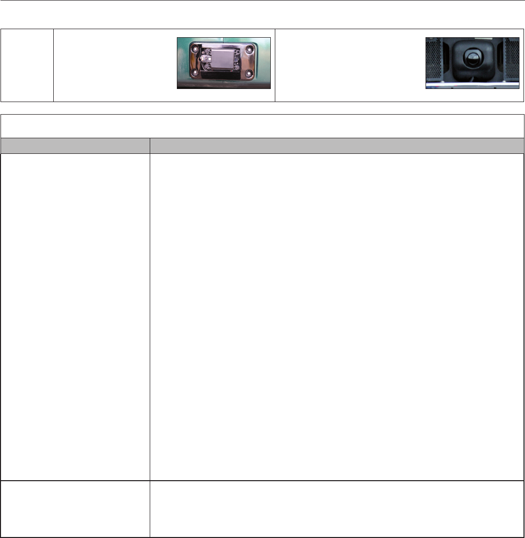
3.1 TROUBLESHOOTING BASICS
Which
radar
sensor is
installed?
The Wingman Advanced
(FLR20) system covered
in this SD sheet has a
at rectangular radar
sensor.
If your Wingman Advanced
system has a black “eyeball”
(FLR10) radar sensor, use
SD sheet SD-61-4962 instead
(formerly SD-13-4962.)

14
3.2 NARROWING DOWN THE PROBLEM
Use the questions found in Table 3.2 below to help assess if the Bendix® Wingman® Advanced™ system is not performing
correctly. Be sure to have a thorough understanding of the system’s normal behavior; this will reduce the troubleshooting
time. The table provides a guide to basic troubleshooting questions and possible corrective actions. Items in Italics
cross-reference to the service procedures in this manual to repair the condition described.
If Bendix Tech Team assistance is needed, prior to calling 1-800-AIR-BRAKE (1-800-247-2725, option 2), complete the
Troubleshooting Checklist (See Appendix E), to help reduce the time needed to troubleshoot the system.
Narrowing Down the Problem (3.2)
Questions Next Steps
Blocked Radar Sensor Issues
Is mud, ice, or snow covering the radar
sensor?
Is anything blocking the view of the radar
sensor?
Clean the radar sensor front surface immediately. Remove anything blocking the
radar sensor then power cycle and read any remaining trouble codes.
Read Section 4.3: Diagnostic Trouble Codes.
Read Appendix A3: FLR20 Radar Sensor Mounting Clearance.
If the vehicle's cruise control is set and the radar sensor is blocked by ice,
snow, mud, tampering, etc. so that it cannot "see" a forward vehicle, Wingman
Advanced may log a diagnostic trouble code (DTC).
After the blockage is removed, the DTC will clear automatically when the vehicle’s
ignition is cycled.
Add a visual check of the radar sensor for blockage to the driver’s pre-trip
inspection checklist.
Potential False Warnings
Do false alerts seem to happen in
construction zones or going under bridges?
Several road scenarios have a tendency to cause false warnings, including
construction zones and bridges. Unless these false warnings are frequent, the
system is likely reacting normally. The driver should not set the cruise control in
construction zones. If driver complaints persist, continue asking questions to more
narrowly dene the driving condition presenting the problems. Review proper
operating conditions in the operator's manual.
Mounting Problems
Is the radar sensor mounting location
(bumper or cross-member) damaged?
• Does the system seem to not "see" as far as
it “used to”, or warn on many more overhead
bridges/signs than previously?
Re-align the radar sensor vertically and laterally. Use the following procedures:
• Inspect the radar mounting. A solid mounting surface is necessary in order
to hold the alignment. If the bumper or mounting cross-member is damaged,
replace it rst, then align the radar sensor.
• Appendix B1 - Go to Appendix B1 and use the owchart to nd out the
procedure needed. Follow the actions directed in the procedure and align
the radar.
• Appendix B4 - Check the vertical alignment and adjust if needed.
Does the mounting bracket look damaged or
tampered with?
Other than expected surface scratches or some discoloration over time, there
should be no visible damage to the radar sensor bracket assembly. If so, realign
the radar sensor vertically and laterally. If radar sensor alignment can not be held in
place, the bracket assembly must be replaced. Verify the bumper is not damaged.
• Check the Vertical Alignment (6.6) and adjust if needed.
• Check the Lateral Alignment (6.8) and adjust if needed.
The Radar Sensor Mounting - The radar sensor needs a solid mounting surface
in order to hold the alignment. If the bumper or mounting cross-member is
damaged, replace it rst, then align the radar sensor.
Other Questions
Has the system worked properly in the past
and is not working correctly now?
This is a good indication that something has changed; review the questions listed
above with the driver to further diagnose the problem.
Has the radar sensor been changed
recently?
If so, the new radar sensor may be incompatible with the vehicle. In addition,
check any system trouble codes with Bendix® ACom® Diagnostics software.
Read Section 4.3: Diagnostic Trouble Codes.
TABLE 4 - NARROWING DOWN THE PROBLEM (PAGES 14-15)

15
Narrowing Down the Problem (3.2)
Questions Next Steps
Did the radar sensor currently on the vehicle
come from another vehicle?
The radar sensor may be incompatible with the new vehicle. Follow Section
1.10: Radar Sensor Interchangeability procedure and check system trouble codes
with Bendix® ACom® Diagnostics software.
Read Section 4.3: Diagnostic Trouble Codes.
With cruise control set, does the system
consistently apply the foundation brakes
when a forward vehicle slows?
This is normal operation. Continue asking the driver questions to determine if
the radar system interventions are not the expected Bendix Wingman Advanced
behavior. If the radar system interventions are not typical, the radar sensor may
be misaligned.
• Inspect the radar mounting. A solid mounting surface is necessary in order
to hold the alignment. If the bumper or mounting cross-member is damaged,
replace it rst, then align the radar sensor.
• Appendix B1 - Go to Appendix B1 and use the owchart to nd out the
procedure needed. Follow the actions directed in the procedure and align
the radar.
• Appendix B4 - Check the vertical alignment and adjust if needed.
The service technician will need to check trouble codes as well. Read Section
4.3: Diagnostic Trouble Codes.
Does a diagnostic trouble code (DTC) seem
to occur when driving through the desert
or in barren areas (no road signs, trees or
vehicles)?
In normal operation, the adaptive cruise control with braking feature of Bendix®
Wingman® Advanced™ system may indicate a DTC if it hasn’t detected a metallic
object after a pre-determined period. This is rare, but most likely to occur when
driving in deserts or barren areas. If the system does set a DTC, Wingman
Advanced provides a visible warning to the driver. In addition, the vehicle also will
drop out of cruise mode, providing an audible and/or visual warning to the driver
as well. The driver must pull off the road, and cycle the ignition to before the
vehicle’s cruise control can be used.
Does the system seem to disengage after an
automatic braking event?
This is normal operation. The driver must set or "resume" the cruise control once
again to regain the following distance function.
Does cruise control disengage sometimes
when the brakes come on and not at other
times?
This is normal operation. When traveling with lightly loaded trailers, or “bobtail”, the
adaptive cruise control with braking feature of Wingman Advanced may continue to
function even after an automatic brake application. No driver input is needed.
Does the connector or wiring appear
damaged?
Wires can become corroded if the radar sensor is not plugged in properly. Clean
the connectors on the wire harness, as well as the radar sensor, and reattach. If
wires are chafed, replace the wire harness. Also, check for trouble codes.
Read Section 4.3: Diagnostic Trouble Codes, and
Section 4.8: Troubleshooting Wiring Harnesses.
Does the system generate a diagnostic
trouble code going down a grade when
using ACB to slow the vehicle, but the code
goes away later?
This is normal operation. The adaptive cruise control with braking feature of
Wingman Advanced is not intended to be used on grades. Verify there are no
diagnostic trouble codes. Proper downgrade driving techniques should be used.
Read Section 4.3: Diagnostic Trouble Codes.
Does the radar sensor have noticeable
damage beyond normal discoloration or
surface scratches?
The radar sensor and bracket are very durable. However, if the radar sensor
housing or cover is cracked or broken, immediately look for trouble codes via a
current version of Bendix® ACom® Diagnostics and replace the damaged radar
sensor. Read Section 4.3: Diagnostic Trouble Codes, and Appendix A.02: Radar
Sensor Mounting.
TABLE 4 - NARROWING DOWN THE PROBLEM (PAGES 14-15)

16
Overview of Possible Issues (3.3)
Issue Description
Vehicle diagnostic
trouble codes
(DTCs)
The Wingman Advanced system will not operate and will set a DTC if any of the following
vehicle systems also show a DTC: engine, engine cruise, instrument cluster, Bendix® ABS,
Bendix® ATC, Bendix® ESP, or transmission. These components must be repaired and
cleared of DTCs before troubleshooting Wingman Advanced. (NOTE: Clearing the vehicle
DTCs may be the only step needed to reestablish full Wingman Advanced functionality. See
Section 4.4: Clearing Diagnostic Trouble Codes (DTCs)
System familiarity Verify the system functionality. Is it operating normally or not? Drivers who are unfamiliar
with the system may report dissatisfaction over the way it beeps or how it activates the
brakes. Use Section 3.0: Introduction to Troubleshooting, Section 4.3: Diagnostic Trouble
Codes and Section 3.1: Troubleshooting Basics to verify if the system is functioning normally;
then continue.
DTCs caused by
temporary operating
conditions
Some Diagnostic Trouble Codes (DTCs) indicate a temporary condition and will clear when
that condition is no longer present. If these persist, further investigation is warranted. See
Section 3.1: Troubleshooting Basics.
Radar sensor
blocked
If the system doesn’t seem to work at all, the radar sensor may possibly be blocked. A DTC
will also be set. Visually inspect it, clear the blockage, turn the ignition on and run through a
power cycle. See Appendix A3 for more information about radar mounting clearance.
Damaged radar
sensor or bracket
If the vehicle has been in an accident, it is likely the radar sensor will need to be re-aligned
or replaced. Inspect the radar sensor and housing for damage. Radar sensor discoloration
or small scratches may be acceptable. Signicant damage (such as cracks, or broken
pieces) will require radar sensor replacement. Regardless of the exterior condition, check
for diagnostic trouble codes outlined in the Section 4.3: Diagnostic Trouble Codes (DTCs) to
determine if radar sensor replacement is necessary.
Damaged connector
or wiring
Visually inspect the connector and wire harness for corrosion or chang. Refer to Sections
4.5: Troubleshooting Diagnostic Trouble Codes: Power Supply and 4.6 Serial Data (J1939)
Communications Link of this document for additional troubleshooting.
Radar sensor
misalignment
Inspect the front of the vehicle. If (a) it has been damaged, or (b) if the vehicle does not track
straight, either of these conditions must be repaired before troubleshooting Wingman Advanced.
If there is a DTC set or if the system does not function, the radar sensor may be severely
misaligned and Wingman Advanced will not operate until this is corrected. See Appendix B -
Bendix Wingman Advanced Radar Alignment.
J1939 network
problems
If the entire system is non-functional, it may be a J1939 network problem. Follow the
instructions in Section 4.6: Serial Data (J1939) Communications Link.
Power to radar
sensor problems
If the entire system is non-functional, another likely cause may be a lack of power to the radar
sensor. Follow the instructions in Section 4.5: Troubleshooting Diagnostic Trouble Codes: Power
Supply.
TABLE 5 - REVIEW OF POSSIBLE ISSUES
3.3 OVERVIEW OF POSSIBLE ISSUES
Some customer issues are actually misunderstandings of how the Bendix® Wingman® Advanced™ system performs
normally. Use Table 5 below to learn the causes of potential issues if Wingman Advanced is not performing correctly.
Some issues can be investigated by a visual inspection. Others may cause a diagnostic trouble code (DTC) to be logged:
See Section 4.3: Diagnostic Trouble Codes.
17
4.0 TROUBLESHOOTING/
DIAGNOSTICS SECTION
FOR FLR10 RADAR SENSORS, SEE SD-61-4962.
Section Index
4.1 Bendix® ACom® Diagnostics Software . . . . .17
4.2 Reading Diagnostic Trouble Codes (DTCs) . .18
4.3 Table of DTCs and Actions to Take . . . . 19-25
4.4 Clearing DTCs . . . . . . . . . . . . . . . . 26
4.5 DTCs: Power Supply . . . . . . . . . . . . 26
4.6 DTCs: J1939 Communications Link. . . . . 26
4.7 (J1939) Test Procedure . . . . . . . . . . . 27
4.8 Troubleshooting Wiring Harnesses . . . . . 27
IMPORTANT NOTE: All vehicle diagnostic trouble
codes related to the engine, transmission,
instrument cluster, engine cruise control and
Bendix® ABS, ATC or ESP® systems must rst be
resolved, with no trouble codes present during
the vehicle operation while in cruise control,
before attempting to diagnose Bendix® Wingman®
Advanced™ diagnostic trouble codes.
4.1 BENDIX® ACOM® DIAGNOSTICS
SOFTWARE
Bendix® ACom® Diagnostics is a PC-based software
program available as a free download from the Bendix
web site (www.bendix.com) or on a CD from the online
Bendix Literature Center (order BW2329). This software
provides the technician with access to all the available ECU
diagnostic information and conguration capability. For
Bendix® Wingman® Advanced™ diagnostics, use a current
version of ACom Diagnostics.
FIGURE 13 - BENDIX® ACOM® DIAGNOSTICS SOFTWARE
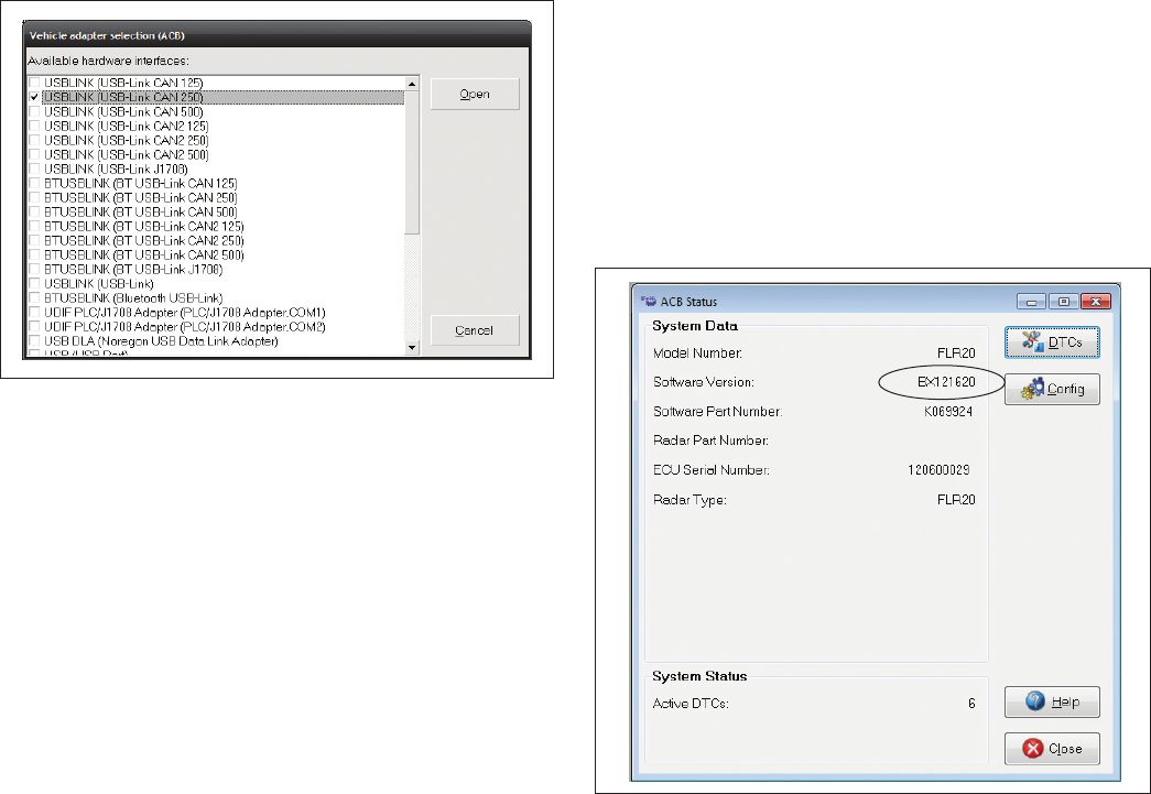
STARTING ACOM® DIAGNOSTICS
The Bendix ACom Diagnostics software can be started from
the desktop shortcut, or from the main Windows® screen
with “Start-Programs-Bendix-ACom® Diagnostics.” See
Figure 14 and also Appendix G. To begin, the technician
selects “Wingman” from the Starter screen, then “Start with
ECU” from the Diagnostic Control panel.
FIGURE 14 - STARTING BENDIX® ACOM® DIAGNOSTICS
SOFTWARE
NOTE: When using ACom Diagnostics for the rst time, the
service technician will be asked to select the communication
adapter for both the Wingman Advanced and Bendix®
EC-60™ controllers. While both controllers will use the
same physical adapter, the technician will need to indicate
which communication protocol to use for each. Once a
successful connection has been made, these steps will
no longer be necessary.
18
The Bendix® ACom® Diagnostics for ABS User Guide is
available for download at www.bendix.com and should be
used as a reference to all functions of the ACom service
tool.
In general, the protocol for Wingman Advanced is described
as CAN or CAN 250. (See Figure 15 for an example of an
adapter compatible with Wingman Advanced). The Bendix®
EC-60™ controller protocol will be described as J1708,
J1587, or Unied Diagnostic Services (UDS).
FIGURE 15 - BENDIX® ACOM® DIAGNOSTICS SOFTWARE -
HARDWARE INTERFACE SCREEN
4.2 READING DIAGNOSTIC
TROUBLE CODES (DTCs)
If the system generates a Diagnostic Trouble Code (DTC),
where a lamp or icon is illuminated on the instrument
cluster or the driver display, then a current version of ACom
Diagnostics software is required. Select “Wingman” from
the starter screen, then “Start with ECU”. Click “DTC”
to show the diagnostic trouble codes. See Appendix G
for screen shots. See Section 4.3 for a complete table
showing DTCs and troubleshooting information.
4.2.1 READING THE SYSTEM
SOFTWARE VERSION
If during troubleshooting, you are asked for the Wingman
Advanced software version, the number is found on the
“Wingman Advanced Status” tab. See Figure 16. Also,
see Section 5.1 for other system indicators.
FIGURE 16 - BENDIX® ACOM® DIAGNOSTICS SOFTWARE -
STARTER SCREEN SHOWING SOFTWARE VERSION

19
4.3 TABLE OF BENDIX® WINGMAN® ADVANCED™ DIAGNOSTIC TROUBLE CODES (DTCs)
NOTE: FLR10 RADAR SENSORS USE DIFFERENT DTCS — SEE SD-61-4962.
Refer to column one for the DTC(s) found and determine the Service Action Code(s) to take. See Tables 6A and 6B below:
Table of Diagnostic Trouble Codes (DTCs), Causes and Recommended Actions for FLR20 Radars
DTC SPN FMI Description
Go to the Service
Action Code List
in Table 6B
1-2 886 14 Internal radar sensor error A
3 886 14 Antenna is dirty or partially blocked C
4 886 4 Battery voltage too low B
5 886 3 Battery voltage too high B
6-10 886 14 Internal radar sensor error A
11 886 14 J1939 wiring harness error or other device DTC K
12-15 886 14 Internal radar sensor error A
16 886 14 Antenna is dirty or partially blocked C
17-27 886 14 Internal radar sensor error A
29 886 14 J1939 Signal Error: Missing AEBS2 message M
30 886 14 J1939 Signal Error: Missing CCVS message M
31 886 14 J1939 Signal Error: Missing CVW message M
32 886 14 J1939 Signal Error: Missing EBC1 message M
33 886 14 J1939 Signal Error: Missing EBC2 message M
34 886 14 J1939 Signal Error: Missing EBC5 message M
35 886 14 J1939 Signal Error: Missing EEC1 message M
36 886 14 J1939 Signal Error: Missing EEC2 message M
37 886 14 J1939 Signal Error: Missing ERC1_DR message M
38 886 14 J1939 Signal Error: Missing ERC1_XR message M
41 886 14 J1939 Signal Error: Missing TD message M
42 886 14 J1939 Signal Error: Missing VDC2 message M
43 886 14 J1939 Signal Error: Missing VDHR message M
44 886 14 J1939 Signal Error: Missing EBC3 message M
45 886 14 Internal radar sensor error A
46 886 7 Radar sensor is misaligned D
47-77 886 14 Internal radar sensor error A
78 886 14 Bendix ABS J1939 Proprietary message signal missing or error state E
79-81 886 14 Internal radar sensor error A
82 3839 16 Adaptive Cruise Control braking overuse F
83 898 13
J1939 Signal ACC1 Engine not properly congured for Wingman Advanced
G
84-85 886 14 Internal radar sensor error A
86 886 14 Conguration mismatch between brake controller and radar sensor H
87 886 14 J1939 Signal Error: Missing VDC1 message M
88 886 14 CMT braking overuse J
92 886 14 J1939 Signal Error: Invalid CCVS1 wheel speed P
93 886 14 J1939 Signal Error: Error in CCVS1 wheel speed N
94 886 14 J1939 Signal Error: Not available CCVS1 wheel speed O
95 886 14 J1939 Signal Error: Invalid CCVS1 CC speed P
TABLE 6A - REFER TO COLUMN ONE FOR EACH DTC CODE FOUND AND FIND ITS SERVICE ACTION CODE.

20
Table of Diagnostic Trouble Codes (DTCs), Causes and Recommended Actions for FLR20 Radars
DTC SPN FMI Description
Go to the Service
Action Code List
in Table 6B
96 886 14 J1939 Signal Error: Error in CCVS1 CC speed N
97 886 14 J1939 Signal Error: Not available CCVS1 CC speed O
98 886 14 J1939 Signal Error: Error CCVS1 CC active N
99 886 14 J1939 Signal Error: Not available CCVS1 CC active O
100 886 14 J1939 Signal Error: Error in CCVS1 CC enable N
101 886 14 J1939 Signal Error: Not available CCVS1 CC enable O
104 886 14 J1939 Signal Error: Invalid CVW GCVW P
105 886 14 J1939 Signal Error: Error in CVW GCVW N
106 886 14 J1939 Signal Error: Not available CVW GCVW O
107 886 14 J1939 Signal Error: Error in EBC1 brake SW N
108 886 14 J1939 Signal Error: Not available EBC1 brake SW O
109 886 14 J1939 Signal Error: Error in EBC1 ABS operate N
110 886 14 J1939 Signal Error: Not available EBC1 ABS operate O
111 886 14 J1939 Signal Error: Invalid EBC2 front axle P
112 886 14 J1939 Signal Error: Error in EBC2 front axle N
113 886 14 J1939 Signal Error: Not available EBC2 front axle O
114 886 14 J1939 Signal Error: Invalid EBC2 LF wheel P
115 886 14 J1939 Signal Error: Error in EBC2 LF wheel N
116 886 14 J1939 Signal Error: Not available EBC2 LF wheel O
117 886 14 J1939 Signal Error: Invalid EBC2 RF wheel P
118 886 14 J1939 Signal Error: Error in EBC2 RF wheel N
119 886 14 J1939 Signal Error: Not available EBC2 LF wheel O
120 886 14 J1939 Signal Error: Invalid EBC2 LR1 wheel P
121 886 14 J1939 Signal Error: Error in EBC2 LR1 wheel N
122 886 14 J1939 Signal Error: Not available EBC2 LR1 wheel O
123 886 14 J1939 Signal Error: Invalid EBC2 RR1 wheel P
124 886 14 J1939 Signal Error: Error in EBC2 RR1 wheel N
125 886 14 J1939 Signal Error: Not available EBC2 RR1 wheel O
126 886 14 J1939 Signal Error: Invalid EBC5 XBR state P
127 886 14 J1939 Signal Error: Error in EBC5 XBR state N
128 886 14 J1939 Signal Error: Not available EBC5 XBR state O
129 886 14 J1939 Signal Error: Error in EBC5 brake Use N
130 886 14 J1939 Signal Error: Not available EBC5 brake Use O
131 886 14 J1939 Signal Error: Invalid EBC5 XBR limit P
132 886 14 J1939 Signal Error: Error in EBC5 XBR limit N
133 886 14 J1939 Signal Error: Not available EBC5 XBR limit O
134 886 14 J1939 Signal Error: Error in EBC5 brake temp N
135 886 14 J1939 Signal Error: Not available EBC5 brake temp O
136 886 14 J1939 Signal Error: Invalid EEC1 engine reference torque P
137 886 14 J1939 Signal Error: Error in EEC1 engine reference torque N
138 886 14 J1939 Signal Error: Not available EEC1 engine reference torque O
139 886 14 J1939 Signal Error: Invalid EEC1 engine speed P
TABLE 6A - REFER TO COLUMN ONE FOR EACH DTC CODE FOUND AND FIND ITS SERVICE ACTION CODE.

21
Table of Diagnostic Trouble Codes (DTCs), Causes and Recommended Actions for FLR20 Radars
DTC SPN FMI Description
Go to the Service
Action Code List
in Table 6B
140 886 14 J1939 Signal Error: Error in EEC1 engine speed N
141 886 14 J1939 Signal Error: Not available EEC1 engine speed O
142 886 14 J1939 Signal Error: Invalid EEC1 driver torque P
143 886 14 J1939 Signal Error: Error in EEC1 driver torque N
144 886 14 J1939 Signal Error: Not available EEC1 driver torque O
145 886 14 J1939 Signal Error: Invalid EEC1 actual torque P
146 886 14 J1939 Signal Error: Error in EEC1 actual torque N
147 886 14 J1939 Signal Error: Not available EEC1 actual torque O
148 886 14 J1939 Signal Error: Invalid EEC2 accelerator pedal position P
149 886 14 J1939 Signal Error: Error in EEC2 accelerator pedal position N
150 886 14 J1939 Signal Error: Not available EEC2 accelerator pedal position O
158 886 14 J1939 Signal Error:
Error in VDC1 Roll Over Protection (ROP) brake contro
l N
159 886 14 J1939 Signal Error: Not available VDC1 ROP brake control O
160 886 14 J1939 Signal Error: Error in VDC1 ROP engine control N
161 886 14 J1939 Signal Error: Not available VDC1 ROP engine control O
162 886 14 J1939 Signal Error: Error in VDC1 YC brake control N
163 886 14 J1939 Signal Error: Not available VDC1 yaw control (YC) brake control O
164 886 14 J1939 Signal Error: Error in VDC1 YC engine control N
165 886 14 J1939 Signal Error: Not available VDC1 YC engine control O
166 886 14 J1939 Signal Error: Invalid VDC2 steer angle P
167 886 14 J1939 Signal Error: Error in VDC2 Steer Angle Sensor (SAS) N
168 886 14 J1939 Signal Error: Not available VDC2 steer angle O
169 886 14 J1939 Signal Error: Invalid VDC2 yaw rate P
170 886 14 J1939 Signal Error: Error in VDC2 yaw rate N
171 886 14 J1939 Signal Error: Not available VDC2 yaw rate O
172 886 14 J1939 Signal Error: Invalid VDC2 long acceleration P
173 886 14 J1939 Signal Error: Error in VDC2 long acceleration P
174 886 14 J1939 Signal Error: Not available VDC2 long acceleration O
175 886 14 J1939 Signal Error: Invalid TSC1 requested torque limit P
176 886 14 J1939 Signal Error: Error in TSC1 requested torque limit N
177 886 14 J1939 Signal Error: Not available TSC1 requested torque limit O
178 886 17 Wingman antenna dirty or partially blocked C
179 886 14 Vehicle cruise control and ACC out of sync K
181 886 14 J1939 Signal Error: EBC1 ABS not fully operational R
182 886 14 J1939 Signal Error: VDC1 VDC not fully operational S
183 886 14 J1939 Signal Error: Error in VDC1 VDC fully operational N
184 886 14 J1939 Signal Error: Not available VDC1 VDC fully operational O
185 886 14 ABS tire size needs recalibration using Bendix® ACom® Diagnostics T
186 886 14 Internal radar sensor error A
187 898 13 J1939 Signal Error: Error in ACC1 ACC mode N
188 898 13 J1939 Signal Error: Not available ACC1 ACC mode O
189 898 13
J1939 Signal CCVS3: Engine not properly congured for Wingman Advanced
G
190-193 886 14 Internal radar sensor error A
TABLE 6A - REFER TO COLUMN ONE FOR EACH DTC CODE FOUND AND FIND ITS SERVICE ACTION CODE.

22
Table 6B: Action Code and the Recommended Service to Use
Service
Action
Letter
Recommended Service (FLR20 Radar Sensors Only)
A
Possible causes:
• Some error conditions may occur at extreme high or low temperatures. These trouble
codes must be diagnosed with the ambient temperature above 32°F (0°C) and below
100°F (38°C).
Perform the following:
• Clear the Wingman Advanced trouble codes using the procedure in Section 4.4: Clearing
Diagnostic Trouble Codes (DTCs).
• If the error returns, call the Bendix Tech Team for assistance at 1-800-AIR-BRAKE (1-800-247-2725,
option 2).
B
Possible causes:
These trouble codes result from incorrect ignition, battery supply voltage, or wiring harness issues as
measured at the radar sensor.
Review the following sections:
• 4.5: Ignition Voltage Too Low
• 4.5: Ignition Voltage Too High
• 4.5: Power Supply Tests
• 4.8: Troubleshooting Wiring Harnesses
Perform the following:
• Verify ignition supply voltage to the radar sensor is between 9 to 16 VDC.
• Visually check for damaged or corroded connectors.
• Visually check for damaged wiring.
• Clear the Wingman Advanced trouble codes using the procedure in Section 4.4: Clearing Diagnostic
Trouble Codes (DTCs). If the error returns, call the Bendix Tech Team for assistance at
1-800-AIR-BRAKE (1-800-247-2725, option 2).
C
Possible causes:
These trouble codes may arise from infrequent conditions that could occur normally.
Perform the following:
• Check for sensor obstruction. Clean dirt or packed snow or ice from the sensor if present.
• Clear the Wingman Advanced trouble codes using the procedure in Section 4.4: Clearing
Diagnostic Trouble Codes (DTCs).
• If the error returns, call the Bendix Tech Team for assistance at 1-800-AIR-BRAKE (1-800-247-2725,
option 2).
D
This DTC is not an indicator of a malfunctioning sensor. Do not replace the sensor.
Possible causes:
Radar sensor OUT OF ALIGNMENT
Perform the following:
• Go to Appendix B1 and use the owchart to nd out the procedure needed. Follow the actions
directed in the procedure and align the radar.
• Clear the Wingman Advanced trouble codes using the procedure in Section 4.4: Clearing Diagnostic
Trouble Codes (DTCs).
• If the error returns, call Bendix for assistance at 1-800-AIR-BRAKE (1-800-247-2725, option 2).
E
This DTC is not an indicator of a malfunctioning sensor. Do not replace the sensor.
Possible causes:
The Wingman system is indicating a required signal from the ABS controller is missing or the ABS is
sending message indicating an error. This DTC could be accompanied by other active DTCs.
Review the following sections:
• 1.10: Radar Sensor Interchangeability
Perform the following:
• Check the ABS for trouble codes using the Bendix’s diagnostic procedures. Some examples are
incorrect ABS ECU software version, incorrect parameter settings, or failure of a component in the
ABS or ESP systems.
• Clear the Wingman Advanced trouble codes using the procedure in Section 4.4: Clearing Diagnostic
Trouble Codes (DTCs).
• If the error returns, call Bendix for assistance at 1-800-AIR-BRAKE (1-800-247-2725, option 2).
TABLE 6B - USE THE SERVICE ACTION CODE FOUND IN TABLE 6A TO FIND THE RECOMMENDED ACTIONS TO TAKE.

23
Table 6B: Action Code and the Recommended Service to Use
Service
Action
Letter
Recommended Service (FLR20 Radar Sensors Only)
F
This DTC is not an indicator of a malfunctioning sensor. Do not replace the sensor.
Possible causes:
• The system was used improperly, such as use of the system on downhill grades.
Perform the following:
• Check any engine, or engine retarder trouble codes.
• Clear the Wingman Advanced trouble codes using the procedure in Section 4.4: Clearing Diagnostic
Trouble Codes (DTCs).
• If the error returns, call the Bendix Tech Team for assistance at 1-800-AIR-BRAKE (1-800-247-2725,
option 2).
G
This DTC is not an indicator of a malfunctioning sensor. Do not replace the sensor.
• The engine has a calibration setting enabling it to perform the torque and retarder control for the
Wingman Adaptive CC.
Possible causes:
• The “ACC-enable” setting in the engine software calibration is not set.
• The engine is not equipped with an engine retarder, or does not support the engine CC option.
Perform the following:
• Check the vehicle and engine manufacturers engine conguration for an engine CC feature.
• Check the engine for an engine retarder feature.
• Check engine conguration for enabling the ACC function.
• If the error returns, call the Bendix Tech Team for assistance at 1-800-AIR-BRAKE (1-800-247-2725,
option 2).
H
Possible causes:
• The controller is recognizing that there are components installed that have part numbers incompatible
with the current system conguration. (For example, when a technician attempts to install a more
recent radar sensor onto a vehicle with an earlier Wingman Advanced or ACB system.) Contact the
dealer or call the Bendix Tech Team at 1-800-AIR-BRAKE (1-800-247-2725, option 2) for the correct
part number to use, or the re-programming steps to take for the newer part number to be accepted:
After addressing the possible causes, perform the following:
• Clear the Bendix® Wingman® Advanced™ system DTCs using the procedure in Section 4.4: Clearing
Diagnostic Trouble Codes (DTCs).
• If the error returns, call the Bendix Tech Team for assistance at 1-800-AIR-BRAKE (1-800-247-2725,
option 2).
J
Possible causes:
• The Collision Mitigation System (CMS) applied the brakes more than three times in a power cycle
and system was used improperly:
After addressing the possible causes, perform the following:
• Clear the Bendix® Wingman® Advanced™ system DTCs using the procedure in Section 4.4: Clearing
Diagnostic Trouble Codes (DTCs).
• Review the operation of Wingman Advanced with the driver.
• If the error returns, call the Bendix Tech Team for assistance at 1-800-AIR-BRAKE (1-800-247-2725,
option 2).
K
This DTC is not an indicator of a malfunctioning sensor. Do not replace the sensor.
• Some system, signal or component caused the Wingman Advanced to be disabled. Engine cruise
control is unavailable and should not operate when the Wingman Advanced is disabled.
Possible causes:
• Check engine, and engine retarder trouble codes. Inspect and troubleshoot the cruise control
system wiring, switches, etc. for proper operation.
After addressing the possible causes, perform the following:
• Clear the Bendix® Wingman® Advanced™ system DTCs by cycling the power. Start the engine.
• If the error returns, call the Bendix Tech Team for assistance at 1-800-AIR-BRAKE (1-800-247-2725,
option 2).
TABLE 6B - USE THE SERVICE ACTION CODE FOUND IN TABLE 6A TO FIND THE RECOMMENDED ACTIONS TO TAKE.

24
Table 6B: Action Code and the Recommended Service to Use
Service
Action
Letter
Recommended Service (FLR20 Radar Sensors Only)
L
This DTC is not an indicator of a malfunctioning sensor. Do not replace the sensor.
Possible causes:
• Mounting offset incorrect.
Perform the following:
• Check the mounting offset of the radar sensor in ACom® Conguration screen. The offset value
should not exceed 500 mm.
• If the error returns, call Bendix for assistance at 1-800-AIR-BRAKE (1-800-247-2725, option 2).
M
Possible causes:
• The Wingman system has not found J1939 signal(s) it is expecting from one or more sources. This
could be accompanied by other active DTCs from the same source.
Review the following sections:
• 1.10: Radar Sensor Interchangeability
• 4.7: J1939 Engine Communications Test Procedure
Perform the following:
• Check the expected source(s) of the signal to identify why the signals have invalid data. A
communication link may be disconnected, the power fuse disconnected or blown, or a change was
made to the controller that was incorrect.
• Clear the Bendix® Wingman® Advanced™ system diagnostic trouble codes using the procedure in
Section 4.4: Clearing Diagnostic Trouble Codes (DTCs).
• If the error returns, call the Bendix Tech Team for assistance at 1-800-AIR-BRAKE (1-800-247-2725,
option 2).
N
This DTC is not an indicator of a malfunctioning sensor. Do not replace the sensor.
Possible causes:
• The Wingman system has found J1939 signal(s) it is expecting, however the values indicate that
there is a malfunctioning component and/or wiring error.
• Some examples of components, sensors or switches that produce J1939 signals are: brake lamp
pressure switches; steering angle sensors; cruise control switches; gross vehicle weight sensors,
various engine torque signals and wheel speed sensors.
Review the following sections:
• 1.10: Radar Sensor Interchangeability
• 4.7: J1939 Engine Communications Test Procedure
Perform the following:
• Check the engine, engine-retarder, body controller or ABS for trouble codes using the manufacturer’s
diagnostic procedures. The controller that broadcasts the error signal must be investigated rst,
however the origin of the signal could potentially be another sensor or switch.
After addressing the possible causes, perform the following:
• Clear the Bendix® Wingman® Advanced™ system DTCs using the procedure in Section 4.4: Clearing
Diagnostic Trouble Codes (DTCs).
• If the error returns, call the Bendix Tech Team for assistance at 1-800-AIR-BRAKE (1-800-247-2725,
option 2).
O
This DTC is not an indicator of a malfunctioning sensor. Do not replace the sensor.
Possible causes:
• The Wingman system has found a J1939 signal, but the function is not supported by the source.
Review the following sections:
• 1.10: Radar Sensor Interchangeability
• 4.7: J1939 Engine Communications Test Procedure
Perform the following:
• Check to see if a change has been made to a controller that is not correct.
After addressing the possible causes, perform the following:
• Clear the Bendix® Wingman® Advanced™ system DTCs using the procedure in Section 4.4: Clearing
Diagnostic Trouble Codes (DTCs).
• If the error returns, call the Bendix Tech Team for assistance at 1-800-AIR-BRAKE (1-800-247-2725,
option 2).
TABLE 6B - USE THE SERVICE ACTION CODE FOUND IN TABLE 6A TO FIND THE RECOMMENDED ACTIONS TO TAKE.

25
Table 6B: Action Code and the Recommended Service to Use
Service
Action
Letter
Recommended Service (FLR20 Radar Sensors Only)
P
This DTC is not an indicator of a malfunctioning sensor. Do not replace the sensor.
Possible causes:
• The Wingman system nds an expected J1939 source, but the signal’s value is out of the normal
operating range.
Review the following sections:
• 1.10: Radar Sensor Interchangeability
• 4.7: J1939 Engine Communications Test Procedure
Perform the following:
• Check the engine, engine retarder, body controller or ABS for DTCs using the manufacturer’s
diagnostic procedures. The controller that broadcasts the signal indicates that a sensor or switch
input is producing a value that is out of the normal operating range.
After addressing the possible causes, perform the following:
• Clear the Bendix® Wingman® Advanced™ system DTCs using the procedure in Section 4.4: Clearing
Diagnostic Trouble Codes (DTCs).
• If the error returns, call the Bendix Tech Team for assistance at 1-800-AIR-BRAKE (1-800-247-2725,
option 2).
R
This DTC is not an indicator of a malfunctioning sensor. Do not replace the sensor.
Possible causes:
• The Wingman system is indicating a required signal that indicates whether the Antilock Brake
System is fully operational or whether its functionality is reduced by: a permanent or temporary
(e.g. low voltage) defect; not congured; not yet fully initialized; or has a loss of input sensors.
S
This DTC is not an indicator of a malfunctioning sensor. Do not replace the sensor.
Possible causes:
• The Wingman system is indicating a required signal that indicates whether the vehicle stability
Roll Over Protection (ROP) or Yaw Control (YC) is fully operational or whether its functionality is
reduced by a permanent or temporary (e.g. low voltage) defect, or not congured or not yet fully
initialized or loss of input sensors.
T
This DTC is not an indicator of a malfunctioning sensor. Do not replace the sensor.
Possible causes:
• The Wingman system is indicating that the ABS tire sizes are out of calibration.
Perform the following:
• Using Bendix® ACom® Diagnostics, go to the ABS Controller Conguration menu and select “Modify”.
Enter the correct tire sizes in the Tire Size [rpm] table for each axle of the vehicle.
After addressing the possible causes, perform the following:
• Clear the Bendix® Wingman® Advanced™ system DTCs using the procedure in Section 4.4: Clearing
Diagnostic Trouble Codes (DTCs).
• If the error returns, call the Bendix Tech Team for assistance at 1-800-AIR-BRAKE (1-800-247-2725,
option 2).
TABLE 6B - USE THE SERVICE ACTION CODE FOUND IN TABLE 6A TO FIND THE RECOMMENDED ACTIONS TO TAKE.
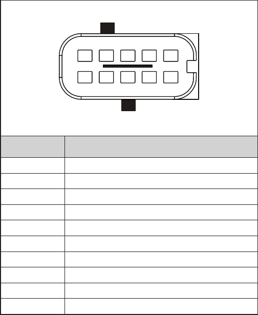
26
4.4 CLEARING DIAGNOSTIC
TROUBLE CODES (DTCs)
This procedure must be used when troubleshooting the
diagnostic trouble codes shown in Table 6.
Clear the Wingman® Advanced™ system Diagnostic Trouble
Codes (DTCs) using the Bendix® ACom® service tool. Click
the “Clear” button located on the “Read / Clear Fault Codes”
screen. Using ignition power only, power off the vehicle
for at least 1 minute. Next, start the engine and run it at
idle for at least 15 seconds.
Drive the vehicle and, on a test track or suitable section
of roadway, engage the cruise control to verify proper
operation.
If the error returns, call Bendix at 1-800-AIR-BRAKE
(1-800-247-2725, option 2) for assistance.
4.5 TROUBLESHOOTING DIAGNOSTIC
TROUBLE CODES: POWER SUPPLY
IGNITION VOLTAGE TOO LOW
Measure the ignition voltage under load. Ensure that the
ignition voltage is greater than 10 VDC (volts DC). Check
the vehicle battery and associated components. Inspect
for damaged wiring, damaged or corroded connectors and
loose connections. Check the condition of the fuse.
IGNITION VOLTAGE TOO HIGH
Measure the ignition voltage. Ensure that ignition voltage
is not greater than 16 VDC. Check the vehicle battery
and associated components. Inspect for damaged wiring,
damaged or corroded connectors and loose connections.
POWER SUPPLY TESTS
1. Take all measurements at the radar sensor harness
connector.
2. Place a load (e.g. 1157 stop lamp) across the supply
voltage and ground connection. Measure the voltage
with the load. The supply voltage on pin 8 to ground
should measure between 10 to 16 VDC (volts DC).
3. Check for damaged wiring, damaged or corroded
connectors and loose connections.
4. Check the condition of the vehicle battery and associ-
ated components. Ensure the connection to ground is
secure and tight.
5. Using the procedures described by the vehicle
manufacturer, check the alternator output for excessive
noise.
Power Supply Pin Codes (4.5)
678910
51234
(Looking into the Front of the Harness Connector)
Pin # Description
1 J1939 High
2 Not Used
3 Not Used
4 Not Used
5 Radar Sensor Ground GND (-)
6 J1939 Low
7 Not Used
8 Supply Voltage IGN (+)
9 Not Used
10 Not Used
TABLE 7 - HARNESS CONNECTOR PINS
4.6 SERIAL DATA (J1939)
COMMUNICATIONS LINK
Check for a loss of communications between the Bendix®
Wingman® Advanced™ system radar sensor, the ABS
controller, the engine ECU, and other devices connected
to the J1939 link. Check for damaged or reversed J1939
wiring. Check for corroded or damaged connectors and
loose connections. Using procedures described by the
vehicle manufacturer, verify the presence of the engine
ECU and the ABS controller on the J1939 link.
Verify the engine ECU conguration. Check for other
devices inhibiting J1939 communications.
27
4.7 ENGINE COMMUNICATIONS
(J1939) TEST PROCEDURE
The Bendix® Wingman® Advanced™ system requires several
J1939 messages from the engine ECU to control the engine
and retarder torque for distance control and braking. The
Wingman Advanced system will set a diagnostic trouble
code if one of these messages is not present.
Use the engine manufacturer’s diagnostic test procedures
to verify that there are no errors present in the engine
that may prevent the Wingman Advanced system from
controlling the engine or retarder torque.
4.7.1 J1939 TROUBLESHOOTING
PROCEDURE
1. Take all measurements at the harness connector unless
otherwise indicated.
CAUTION: DO NOT INSERT PROBES INTO THE BACK
SIDE OF THE CONNECTOR AS THIS WILL DAMAGE THE
SEAL AROUND THE WIRE.
CAUTION: DO NOT INSERT ANY PROBE INTO THE
PIN ON THE MATING CONNECTOR OF THE RADAR
SENSOR THAT IS GREATER THAN 0.62 MM DIAMETER
OR SQUARE. THIS WILL DAMAGE THE CONNECTOR PIN
AND REQUIRE REPLACEMENT OF THE HARNESS.
2. Check for damaged or reversed J1939 wiring.
If the J1939 HIGH or J1939 LOW wiring circuits are
damaged, such as shorting together, the entire J1939
link will be lost. The problem may be intermittent,
enabling the J1939 link to operate normally sometimes.
In that event, multiple diagnostic trouble codes will be
logged in multiple engine and vehicle controllers.
If the J1939 HIGH and J1939 LOW wiring circuits are
reversed, communication over the entire J1939 link will
not be lost. Only those devices that are outside of the
problem point from other devices will not receive, or be
able to transmit, data messages.
3. Check for corroded or damaged wiring connector
problems such as opens or shorts to voltage or ground.
If the connector terminals are corroded, this may be
an indication of water intrusion into the wiring system
and possibly into the radar sensor. Replacement of
the entire harness is recommended. If the terminals
of the radar sensor are corroded, replacement of the
radar sensor is recommended.
4. Check for other J1939 devices which may be inhibiting
J1939 communication. The service technician should
consult the vehicle manufacturer’s procedures for
other J1939 troubleshooting procedures. The device’s
power should be removed and measurements made at
the ECU pins for shorts to ground and power pins and
resistance between the J1939 HIGH or J1939 LOW
input circuits.
5. Unplug the radar sensor. With the ignition switch off,
measure the resistance (ohms) using a multimeter
between harness pins 1 and 8. The reading should be
approximately 60 ohms. If it is not, the vehicle wiring
should be investigated using procedures described by
the manufacturer.
6. Unplug the radar sensor. With the ignition switch off,
using a multimeter, measure the resistance in ohms,
between harness pin 1 and ground. The measurement
should indicate an open circuit or very high resistance.
If this is not the case, the vehicle wiring should be
investigated using procedures described by the
manufacturer.
7. Unplug the radar sensor. With the ignition switch off,
using a multimeter, measure the resistance in ohms,
between harness pin 8 and ground. The measurement
should indicate an open circuit or very high resistance.
If this is not the case, the vehicle wiring should be
investigated using procedures described by the
manufacturer.
4.8 TROUBLESHOOTING
WIRING HARNESSES
All wire harness connectors must be properly seated to
maintain environmental seals. Push the mating connector
until it seals with a click. Press the orange locking tab
towards the center of the radar. When replacing an
Advanced radar sensor, check that the wire harness
connector is free of corrosion before plugging into a new
radar sensor. Check for corroded or damaged wiring
connector problems such as opens or shorts to voltage
or ground.
If the connector terminals are corroded, this may be an
indication of water intrusion into the wiring system and
possibly into the radar sensor. Replacement of the entire
harness is recommended. If the terminals of the radar
sensor are corroded, replacement of radar sensor is
recommended.
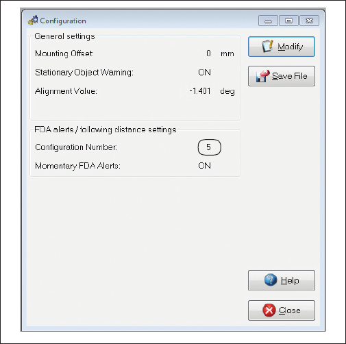
28
5.0 OTHER SYSTEM FEATURES SECTION
Section Index
5.1 Reading Bendix® Wingman® Advanced™
System Key Indicators . . . . . . . . . . . 28
5.2 Diagnostic Trouble Code (DTC)
Self-Clearing . . . . . . . . . . . . . . . . . 28
5.3 Following Distance Adjustment Switch
(Optional) . . . . . . . . . . . . . . . . . . 28
5.4 Conguring Wingman Advanced Following
Distance Alerts . . . . . . . . . . . . . . . . 29
5.5 Extracting Bendix Wingman Advanced
System Data . . . . . . . . . . . . . . . . . 30
5.5.1 Data Availability . . . . . . . . . . . . . . . 30
5.5.2 Data Overview . . . . . . . . . . . . . . . . 30
5.5.3 Extracting Data and Saving a Report . . . . 31
5.1 READING BENDIX® WINGMAN®
ADVANCED™ SYSTEM KEY INDICATORS
To check the Bendix Wingman Advanced system key
indicators such as software version number, use a current
version of Bendix® ACom® Diagnostics software. From the
main menu of ACom Diagnostics software, the technician
highlights Advanced, then clicks “Start with ECU”. The
Advanced Status screen will appear. Clicking “Cong” will
display the key system indicators. See Section 4.21 for an
example of reading the software version. See Figure 17 for
an example of ACom software conguration information.
See Appendix H.
NOTE: ACom® Diagnostics is also used for troubleshooting
Bendix® ESP®, ATC, and ABS systems.
FIGURE 17 - BENDIX® ACOM® SCREEN SHOWING
CONFIGURATION NUMBER
5.2 BENDIX WINGMAN ADVANCED
DIAGNOSTIC TROUBLE CODE
(DTC) SELF-CLEARING
Many of the diagnostic trouble codes (DTCs) will
automatically clear when the cause of the problem is
corrected. When the technician troubleshoots a diagnostic
trouble code, it is recommended that a current version of
the Bendix® ACom® Diagnostics software be used to clear
the diagnostic trouble codes as directed by the repair
procedure.
Some codes will clear immediately and the functionality
will resume. Some codes will clear after powering off the
ignition for about 1 minute and then turning it back on.
Other codes will clear after the engine runs for about 15
seconds.
If the vehicle’s cruise control can be engaged, that indicates
all Wingman Advanced trouble codes have been cleared.
5.3 FOLLOWING DISTANCE ADJUSTMENT
SWITCH (OPTIONAL)
If the vehicle is equipped with the following distance
adjustment switch and the following distance does not
change after an adjustment is made, the switch, wiring,
or a controller on the vehicle should be checked using
the diagnostic procedures described by the vehicle
manufacturer. The radar sensor receives the driver’s
desired following distance on the J1939 data communication
link from a controller on the vehicle. No diagnostic trouble
code will be set if the vehicle is not equipped with a following
distance adjustment switch.

29
Conguring Wingman Advanced Following Distance Alerts (5.4)
Conguration
No.
Option
Following Distance
Audible Alert (sec.)
Default
Advanced
Following
Distance
(seconds)
Alert 1:
Slow
Alert 2:
Medium
Alert 3:
Fast
1
City — — 0.5
2.8
Highway (>37 mph) 1.5 1.0 0.5
2
City — — 0.5
3.5
Highway (>37 mph) 1.5 1.0 0.5
3
City — 1.5 1.0
2.8
Highway (>37 mph) 2.0 1.5 1.0
4
City — 1.5 1.0
3.5
Highway (>37 mph) 2.0 1.5 1.0
5
City — 1.5 1.0
3.5
Highway (>37 mph) 3.0 2.0 1.0
6
City 3.0 1.5 1.0
3.5
Highway (>37 mph) 3.0 2.0 1.0
7
City — — 0.2
2.8
Highway (>37 mph) — — 0.2
8
See Note
Below
City — — 0.5
1.7
Highway (>37 mph) 1.5 1.0 0.5
9
See Note
Below
City — — 0.5
2.3
Highway (>37 mph) 1.5 1.0 0.5
TABLE 8 - CONFIGURING FOLLOWING DISTANCE ALERTS (FDA).
Note: Congurations 8 and 9 are available on select applications only and may not be available on your system.
5.4 CONFIGURING BENDIX® WINGMAN® ADVANCED™ FOLLOWING DISTANCE ALERTS
Multiple alert and distance setting strategies, known as Following Distance Alert (FDA) congurations, can be chosen using
the Bendix® ACom® Diagnostics tool. In current versions of ACom software, the service technician will nd a selection
box called “Conguration Number” which gives the service technician the choices shown in Figure 18 and in Table 8.
See Appendix B for an example of following distance alerts for systems where a Bendix® Driver Interface Unit (DIU) is used.
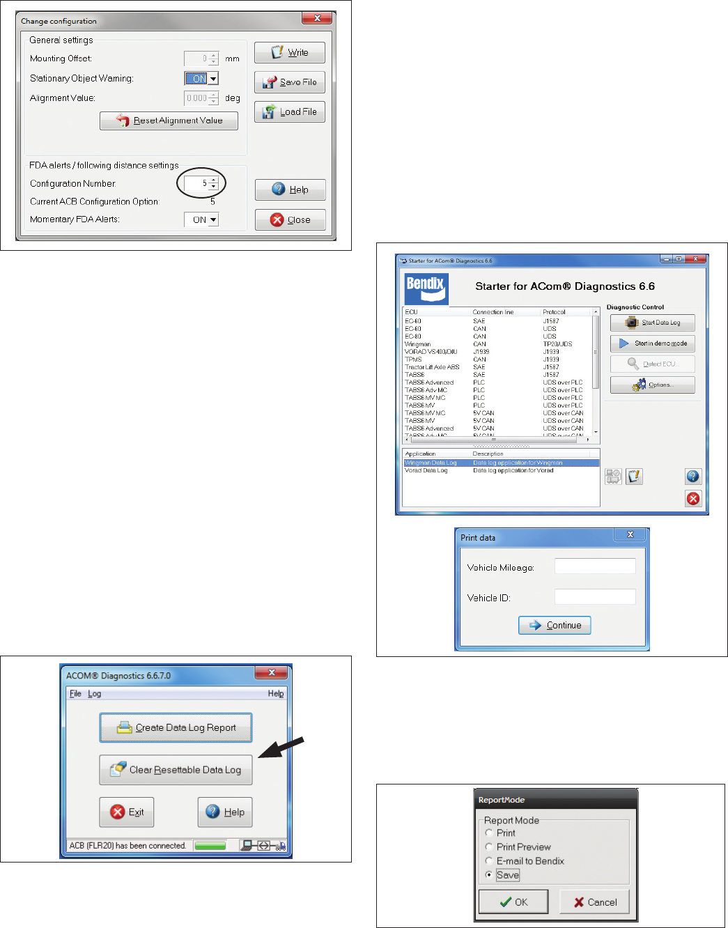
30
FIGURE 18 - BENDIX® ACOM® DIAGNOSTICS –
CONFIGURATION NUMBER (SHOWING CONFIGURATION
ONE SELECTED). SEE ALSO TABLE 8.
Changing conguration allows the eet user to adjust both
the following distance alerts and the following distance
behind a detected forward vehicle. See Figure 18.
5.5 BENDIX® WINGMAN® ADVANCED™
SYSTEM DATA
NOTE: A license key is required from Bendix in order to
engage the data collection ability of the system. Call the
Bendix Tech Team at 1-800-AIR-BRAKE (1-800-247-2725,
option 2) for more information.
5.5.1 DATA AVAILABILITY
Contact Bendix (1-800-AIR-BRAKE (1-800-247-2725,
option 2)) for the ACom Diagnostics software license key
and the set-up procedure.
Data will not be stored by the system until the “Clear
Resettable Data Log” (see Figure 19) is selected and the
proper Bendix® ACom® Diagnostics license key is present.
FIGURE 19 - CLEARING THE RESETTABLE DATA LOG
5.5.2 DATA OVERVIEW
At the eet’s discretion, Wingman Advanced makes data
available (see Figure 22), in a data log, regardless of whether
or not Advanced is used. The log can be reset using the
Bendix ACom Diagnostics software as often as needed.
5.5.3 EXTRACTING DATA AND
SAVING A REPORT
The Bendix ACom Diagnostics tool and User
Guide is available online at “ABS Software” link un-
der “Services and Support” on the Bendix website
(www.bendix.com).
After a successful connection, the service technician will
be presented with the window shown in Figure 20.
Select “Start ACB Data Log”. The service
technician will be asked to enter the vehicle ID and
mileage. This data will be stored in the report.
See Figure 20.
FIGURE 20 - VEHICLE DATA
The service technician can choose whether to “Print”,
“Print Preview”, “E-mail”, or “Save” the report to disk. See
Figure 21. The data can be saved as a comma delimited
le or an HTML web page le.
See Figure 22 on next page for a sample report.
FIGURE 21 - REPORT MODE
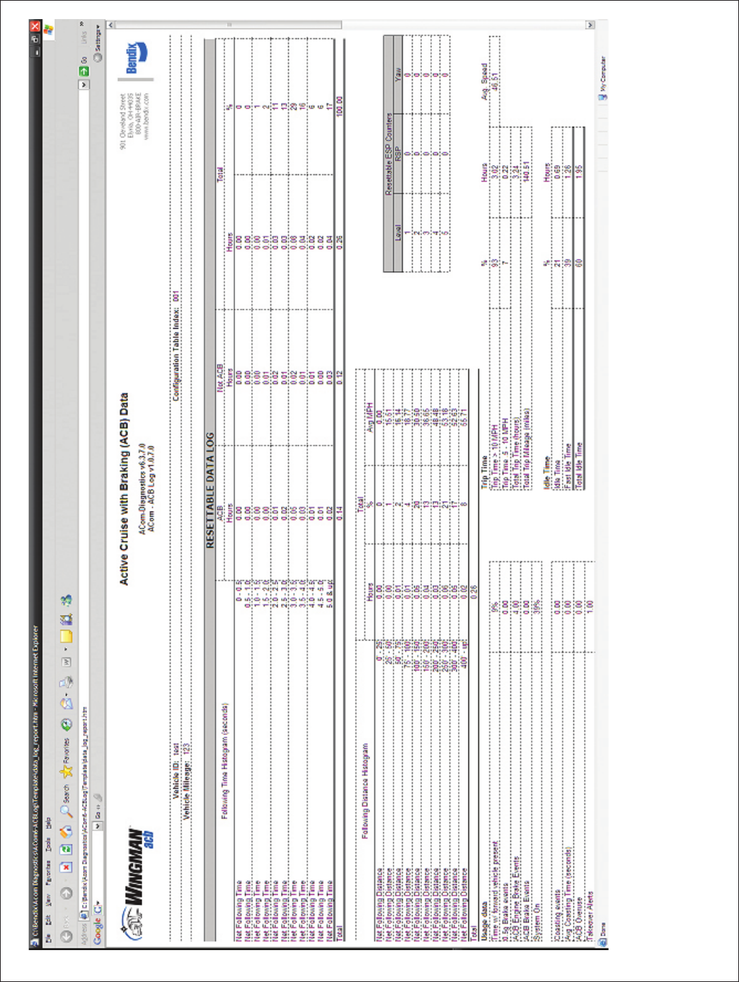
31
FIGURE 22 - TYPICAL WINGMAN ADVANCED VEHICLE REPORT
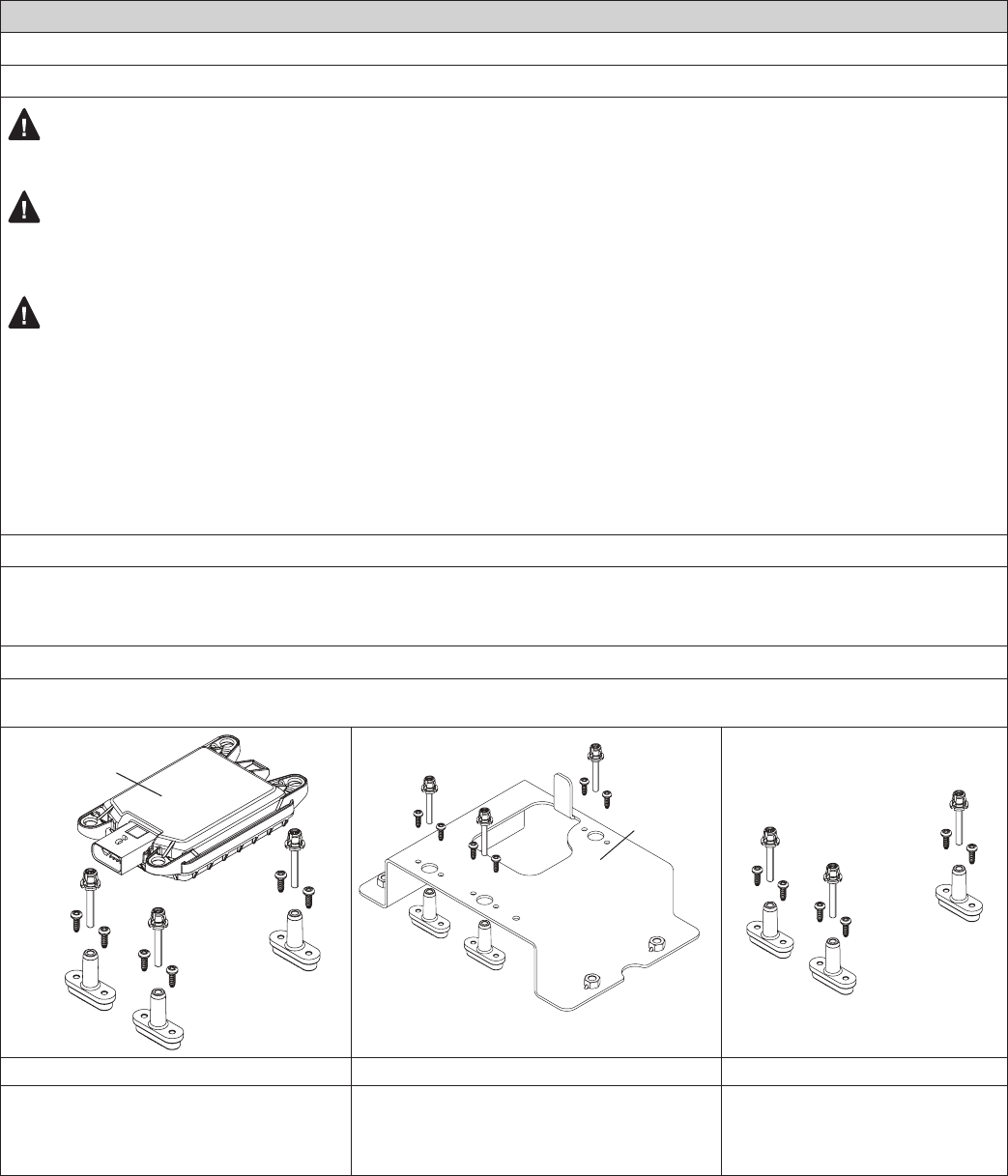
32
APPENDIX A - RADAR MOUNTING
Appendix A
Appendix A
Bendix® FLR20™ Radar Mounting
GENERAL
WARNING: Improper use of the Bendix® Wingman® Advanced™ system can result in a collision causing
property damage, serious injuries, or death.
WARNING: Under no circumstances must the radar be removed or repositioned from the original production
line installation. The assembly should always be mounted in the original OEM location. If this location is not in the
center of the vehicle, the mounting offset will need to be programmed through Bendix® ACom® Diagnostics software.
CAUTION: Vehicle equipment, including bumpers, deer guards, etc. must not infringe upon the zone used
by the radar sensor to emit and receive radar waves. See Appendix A3. Failure to comply with this requirement
will impair the function of the radar. Only vehicle OEM-approved covers and/or cover panels may be installed
in front of the radar.
The radar sensor assembly is mounted to the front of the vehicle using an adjustable bracket. This adjustable bracket
allows for the radar sensor to be properly aimed laterally and vertically to maximize Wingman Advanced system
performance. When mounting a radar sensor, the wire harness connector should always point towards the passenger
side of the vehicle.
A.1 VEHICLE APPLICATIONS
The radar sensor can be mounted and installed only on vehicles that have Bendix Wingman Advanced already installed.
At this time Wingman Advanced cannot be retrotted onto vehicles, even if that vehicle is equipped with the Bendix®
ESP® stability system.
A.2 REPLACEMENT PARTS
Replacement parts exist for all components shown below. Parts are available from any Bendix authorized parts supplier.
ADJUSTABLE
STAND-OFF
ASSEMBLIES
(3)
RADAR
SOURCE ADAPTER
BRACKET
(VARIES)
Radar Sensor with Stand-off Assemblies Bracket (Varies) and Stand-off Assemblies Stand-off Assemblies Only
• Kit K071772 includes a specically-
programmed Bendix® FLR20™ radar sensor,
three stand-off adjustor assemblies, and six
mounting screws.
• Provide the bracket part number (see label)
when ordering replacements. Kits will include
three stand-off adjustor assemblies, and six
mounting screws.
• Kit K073199 includes three stand-
off adjustor assemblies, and six
mounting screws.
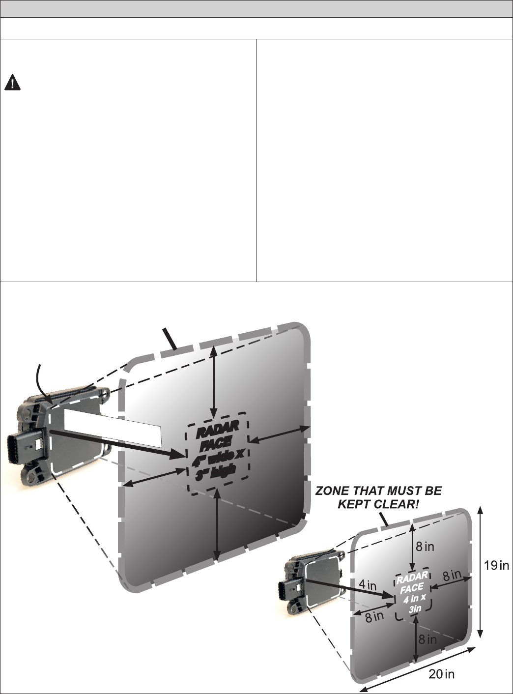
33
2xA
2xA
2xA
2xA
Measure from the raised
surface at the front of the radar
Distance A
ZONE THAT MUST BE
KEPT CLEAR!
RADAR
FACE
4" wide x
3" high
Appendix A
Example Below: If an obstruction
is four inches in front of the radar, it
must be outside of a zone 20 inches
wide by 19 inches high.
The only exceptions are vehicle OEM-approved covers
Keep all deer and moose guards,
bumpers, etc. outside of the required
radar beam clearance area.
Appendix A
Bendix® FLR20™ Radar Mounting
A3 BENDIX® FLR20™ RADAR
SENSOR MOUNTING CLEARANCE
CAUTION: Vehicle equipment, including bumpers,
deer guards, etc. must not infringe upon the zone used
by the radar sensor to emit and receive radar waves.
Failure to comply with this requirement will impair
the function of the radar. Only vehicle OEM-approved
covers and/or cover panels may be installed directly
in front of the radar.
For proper operation of your Wingman Advanced system,
adhere to the following guidelines:
• The radar sensor assembly should be OEM-installed
on the vehicle following all OEM specications.
• The radar’s eld of view must NOT have interference
from any other vehicle components such as bumpers,
cow-catcher bumpers, engine blankets, seasonal
decorations, or any other commonly mounted front-of-
vehicle components. The radar signal is emitted from
the front of the sensor with a spreading beam. In order
to ensure that no adverse interference is experienced
from bumpers or other nearby vehicle equipment, a
suitable clearance must be maintained around the
radar. This clearance must be maintained regardless if
the vehicle is stationary or in motion. See the diagram
below for a general guide and an example of how to
calculate the zone required.
NOTE: Bendix does not certify nor offer warranty on
Bendix Wingman systems where system performance is
affected by beam obstructions of any kind or unapproved
post-production covers. This document gives general
guidelines that will work for most vehicles; exceptions
may exist.
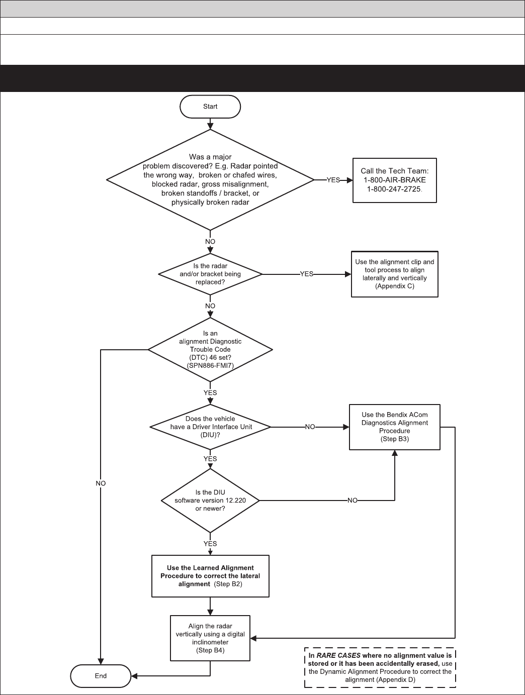
34 Appendix B
APPENDIX B - RADAR ALIGNMENT
Appendix B
Bendix® FLR20™ Radar Alignment
B1.0 RADAR ALIGNMENT ALIGNMENT FLOWCHART
For Bendix® FLR10™ radar sensors, see SD-61-4962.
Use this owchart to nd which section(s) of this Appendix to use.
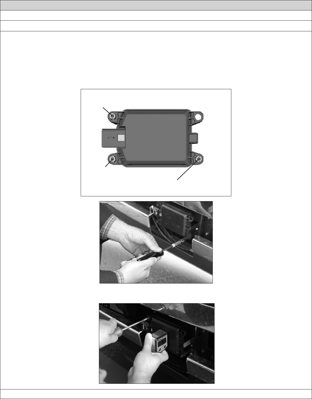
35
Appendix B
Appendix B
Bendix® FLR20™ Radar Alignment
B1.1 GENERAL INFORMATION ABOUT ADJUSTING THE ALIGNMENT
Accurate vertical and lateral alignment of the radar sensor is critical for proper operation of Bendix® Wingman®
Advanced™. If the alignment is outside a certain range it could cause false warnings, missed warnings and a diagnostic
trouble code in the system.
The radar sensor is mounted to the front of the vehicle using a bracket with three stand-offs, two of which are used
when making adjustments, if necessary.
It is important to use the correct stand-off when making any alignment adjustments.
Use a Torx T-20 screwdriver here to
adjust for the vertical alignment
Use a Torx T-20 screwdriver here to
adjust for the lateral alignment
IMPORTANT:
Do not adjust
this stand-off!!
ABOVE: A TECHNICIAN MAKES AN ADJUSTMENT TO THE LATERAL ALIGNMENT STANDOFF.
BELOW: THE VERTICAL ALIGNMENT STANDOFF IS ADJUSTED.
Call the Bendix Tech Team at 1-800-AIR-BRAKE (1-800-247-2725, option 2) for troubleshooting assistance.
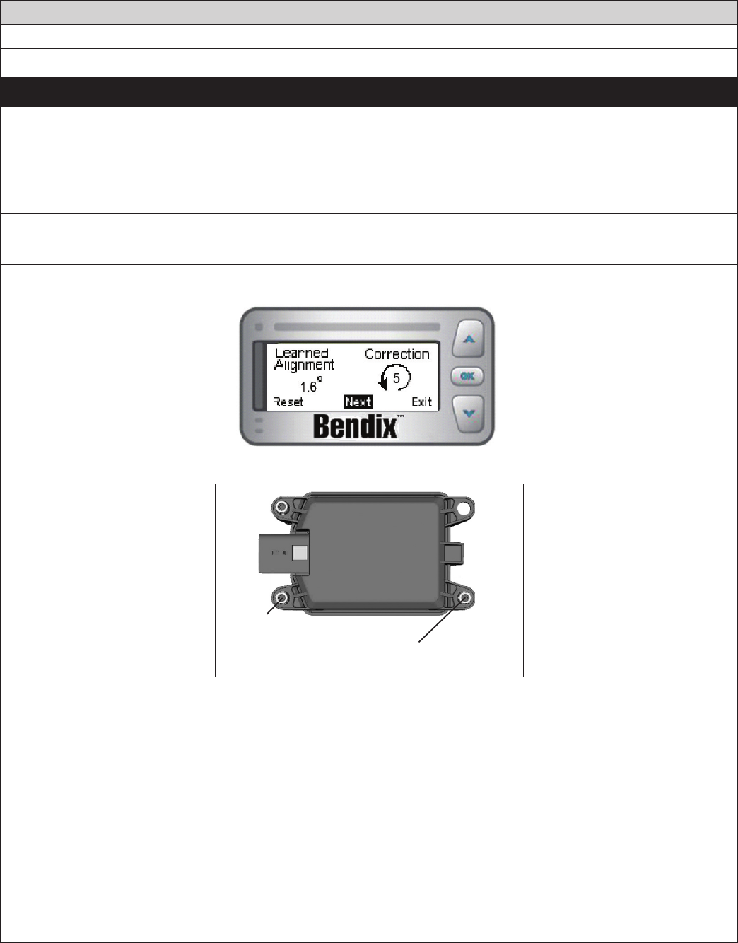
36 Appendix B
Appendix B
Bendix® FLR20™ Radar Alignment
B2 LATERAL ALIGNMENT USING THE LEARNED ALIGNMENT SCREEN
This is the preferred and recommended method for lateral alignments
This method is for vehicles with Bendix® DIU® displays that use software whose version is 12.220 and above. To verify
the DIU’s software version go to the Volume screen, where it is displayed in the top right-hand corner.
If the radar’s lateral alignment is not correct, the system calculates over the course of many hours of driving, an alignment
adjustment value. The DIU displays the learned alignment value, and also shows the technician the direction to turn,
and number of turns to make to, the lateral alignment adjustment screw.
B2.1 Tools needed: DIU (with software version 12.220 or above), and a Torx T-20 Screwdriver.
B2.2 Enter the DIU menu item titled “Radar” and select “Alignment Check”.
B2.3 Upon selecting the “Alignment Check” menu item the following screen will be displayed:
Bendix® DIU Screen Showing learned alignment value
Use a Torx T-20 screwdriver here to
adjust for the lateral alignment
IMPORTANT:
Do not adjust
this stand-off!!
For example, the Figure above shows a correction value of ve (5) full turns counterclockwise is needed. The
correction count and arrow direction displayed shows that in order to adjust the radar to be correctly aligned
with the travel of the vehicle, the lateral adjustment screw (lower right screw when facing the front of the vehicle)
should be turned.
B2.4 Make the adjustment shown on the DIU.
IMPORTANT: Make necessary adjustments to the alignment standoff prior to resetting the alignment value.
B2.5 Select “Reset” and then “Exit” on the Bendix DIU screen to return to the default screen.
B2.6 Cycle the ignition power.
B2.7 IMPORTANT: Before returning the vehicle to service, go to Section B4 and check the vertical alignment.
NOTE: The alignment process is complete after the vertical alignment has been checked (and adjusted, if
necessary.) You do not need to test-drive the vehicle.
Call the Bendix Tech Team at 1-800-AIR-BRAKE (1-800-247-2725, option 2) for troubleshooting assistance.
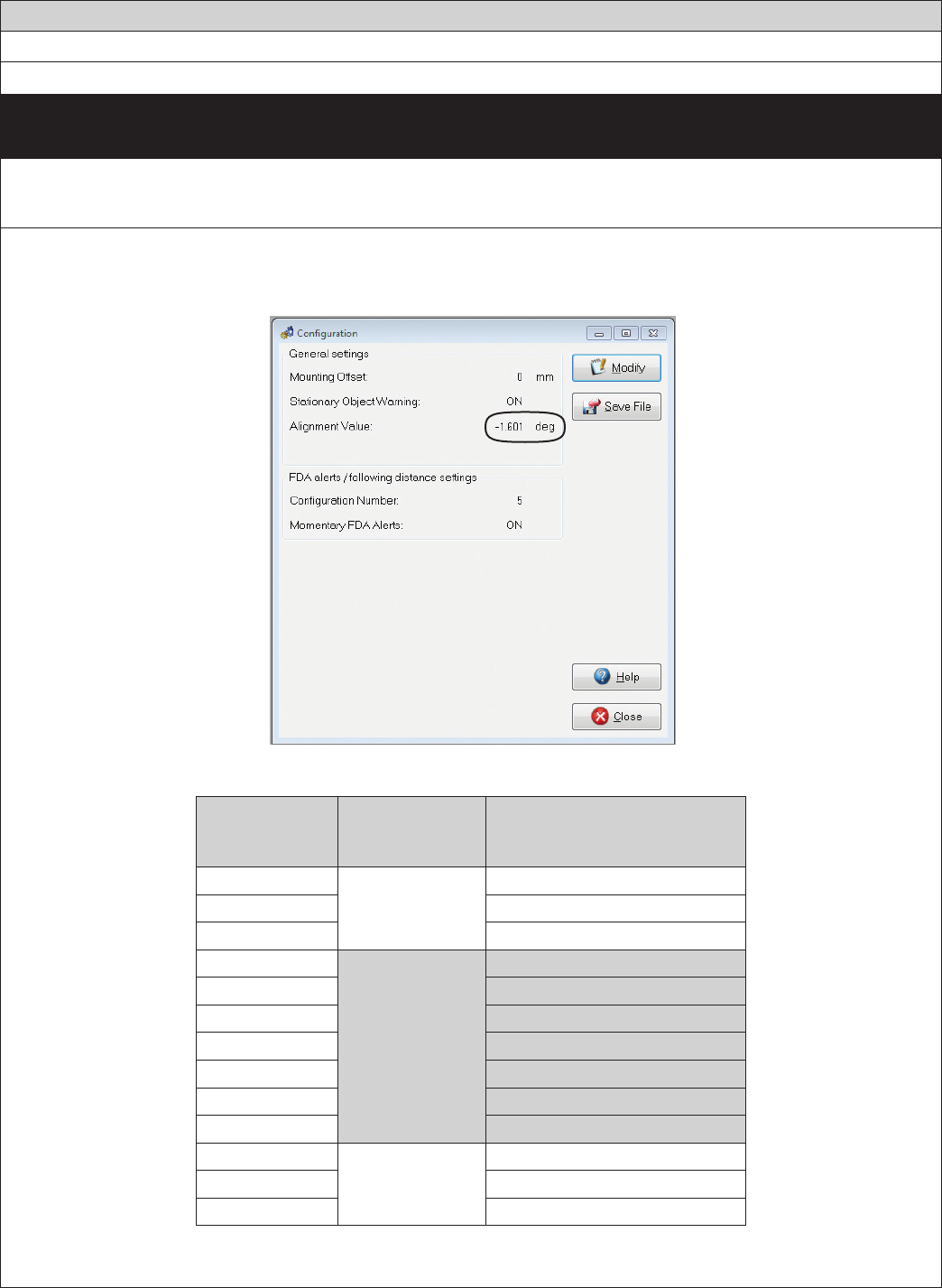
37
Appendix B
Appendix B
Bendix® FLR20™ Radar Alignment
B3 LATERAL ALIGNMENT USING BENDIX® ACOM® DIAGNOSTICS
Use this method to align the Bendix FLR20 laterally when the vehicle
does not have a DIU, or has a DIU (but its software version is prior to 12.220)
B3.1 Tools needed: Bendix ACom Diagnostics, and a Torx T-20 Screwdriver
B3.2 Connect the vehicle to a laptop computer with the current release of the Bendix ACom Diagnostics software.
B3.3 See the “Alignment Value” shown on the Conguration screen.
If the alignment value shown by ACom Diagnostics is between -1.1° and 1.1 °, this is acceptable and the system
should operate normally. A value outside that range means the radar sensor should be adjusted.
BENDIX® ACOM® DIAGNOSTICS SCREEN SHOWING ALIGNMENT VALUE
Alignment
Value Range
(Degrees)
Service Action
Number of Full Turns of
the Lateral Alignment
Adjustment Screw
-2.0 to -1.8 Adjustment
Required
6 clockwise
-1.7 to -1.6 5 clockwise
-1.5 to -1.2 4 clockwise
-1.1 to -0.8
No Adjustment
Needed
3 clockwise (optional)
-0.7 to -0.5 2 clockwise (optional)
-0.4 to -0.3 1 clockwise (optional)
-0.2 to 0.2
0.3 to 0.4 1 counterclockwise (optional)
-0.5 to 0.7 2 counterclockwise (optional)
0.8 to 1.1 3 counterclockwise (optional)
1.2 to 1.5 Adjustment
Required
4 counterclockwise
1.6 to 1.7 5 counterclockwise
1.8 to 2.0 6 counterclockwise
ADJUSTMENT SCREW ROTATION REQUIRED
Note: The maximum Alignment Value shown by ACom Diagnostics is two degrees (plus or minus).
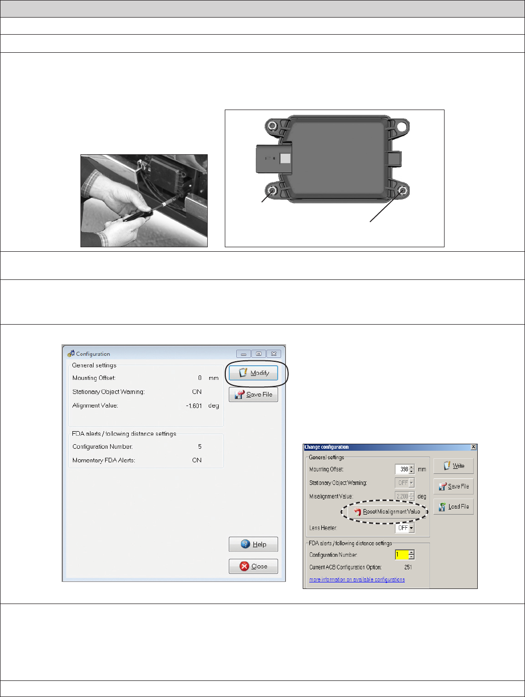
38 Appendix B
Appendix B
Bendix® FLR20™ Radar Alignment
B3 LATERAL ALIGNMENT USING BENDIX® ACOM® DIAGNOSTICS (CONTINUED)
B3.4 See the image below to see the lateral alignment adjustment screw location.
Use Table in B3.3 to nd the number of full turns of the stand-off adjustment screw required to bring the radar
sensor back into alignment. A Torx T-20 screwdriver with a mark or other indicator may help track the number
of turns.
Use a Torx T-20 screwdriver here to
adjust for the lateral alignment
IMPORTANT:
Do not adjust
this stand-off!!
B3.5 After making the adjustment, clear the Bendix® Wingman® Advanced™ system Diagnostic Trouble Code (DTC)
using the procedure in Section 4.4: Clearing Diagnostic Trouble Codes (DTCs).
B3.6 Then follow steps B3.7-12 to reset the alignment value stored in the system.
B3.7 Procedure to Reset the Alignment Value. Select Wingman Advanced on the starter screen, and then select
“Start with ECU.” Select “Cong” on the Wingman Advanced Status window.
B3.8 Select “Modify” on the Conguration Status window.
BENDIX® ACOM® DIAGNOSTICS: CONFIGURATION AND CHANGE CONFIGURATION SCREENS
B3.9 Select “Reset Alignment Value” in the Change Conguration box. (See Appendix H for more details.)
B3.10 Close the ACom Diagnostics program and any open windows.
B3.11 Cycle the vehicle ignition.
B3.12 After the vehicle has been driven at least 20 miles at above 35 mph in multi-lane urban trafc, re-check the
alignment value using ACom Diagnostics.
Call the Bendix Tech Team at 1-800-AIR-BRAKE (1-800-247-2725, option 2) for troubleshooting assistance.
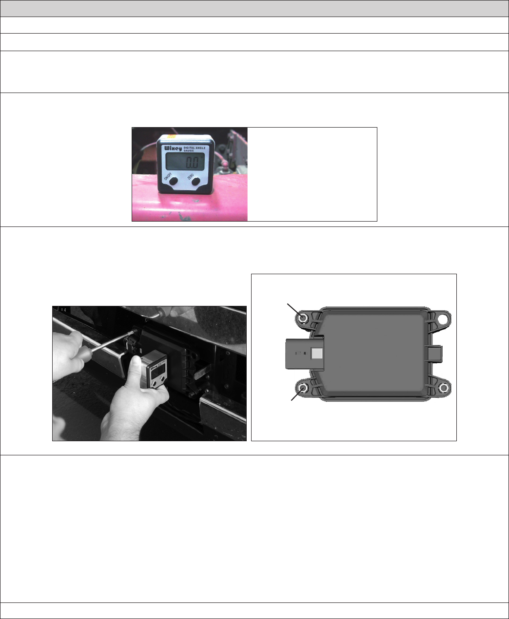
39
Appendix B
Appendix B
Bendix® FLR20™ Radar Alignment
B4 VERTICAL ALIGNMENT USING AN INCLINOMETER
B4.1 Tools Needed: A digital inclinometer, Torx T-20 screwdriver. (If a clip from the Bendix Alignment Tool kit is
available, the clip may be placed over the front of the radar sensor during this process.)
B4.2 Park the vehicle on a level oor. Air suspensions must be charged and stable.
B4.3 Calibrate (or “zero”) the inclinometer on a horizontal section of the frame rail. Follow the manufacturer’s
instructions (typically digital inclinometers have a “SET” button for this purpose).
Calibrate (or “zero”)
the Digital Inclinometer
on a Cab Frame Rail
in the direction that the
vehicle travels.
B4.4 Place the calibrated digital inclinometer against the front surface of the radar, so that the tool is held in the
same direction as it was on the rail. With the digital inclinometer resting as shown, verify that the
display shows 0° (± 1.5°) from vertical, when measured by an inclinometer set to zero on the vehicle’s frame.
Use a Torx T-20 screwdriver here to
adjust for the vertical alignment
IMPORTANT:
Do not adjust
this stand-off!!
NOTE: Complete the steps below only if a vertical adjustment is necessary.
B4.5 Use the Torx T-20 screwdriver to turn by hand the top-left adjustment stand-off. During the adjustment, observe
the digital display on the inclinometer and turn the vertical alignment screw clockwise or counterclockwise
depending on the vertical direction (up or down) needed, until the reading is zero degrees.
B4.6 The radar is aligned vertically when the display is between -1.5° and 1.5°, however to achieve a more
precise alignment, adjust the vertical alignment screw until the digital alignment value is near zero (0°).
Note: The alignment process shown here is for Bendix alignment brackets. For other brackets, similar alignment
steps will be needed; consult the vehicle manual for full instructions.
B4.7 If used, be sure to remove the clip before returning the vehicle to service.
Call the Bendix Tech Team at 1-800-AIR-BRAKE (1-800-247-2725, option 2) for troubleshooting assistance.
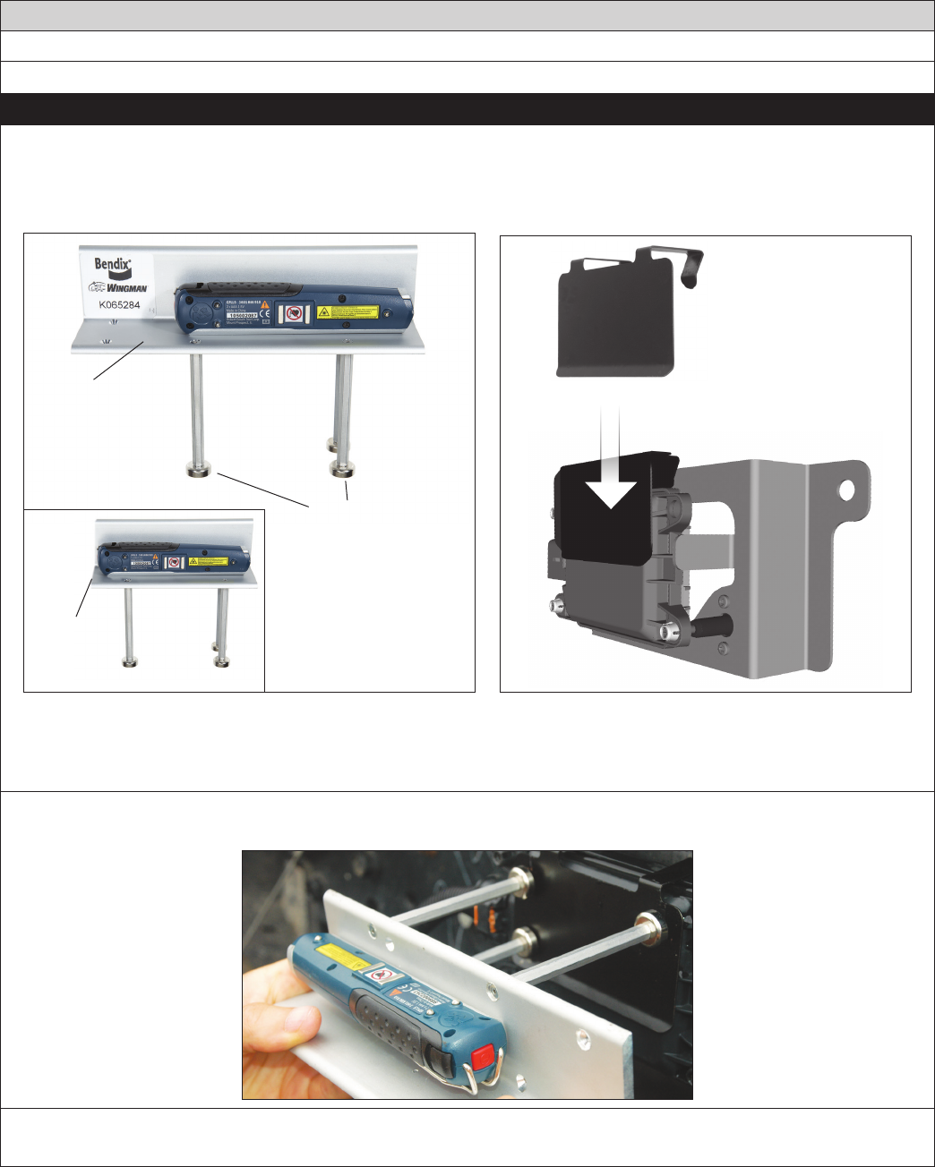
40
Appendix C
Bendix® FLR20™ Radar Alignment
C1 LATERAL ALIGNMENT USING THE BENDIX® ALIGNMENT CLIP AND TOOL
This is the method to use for lateral alignment when a radar and/or bracket is replaced.
Tools needed: Bendix® alignment kit, steel clip, Torx T-20 screwdriver and a tape measure.
• One of the Bendix® Alignment Tools part no: K065284 and K096579 — available from Bendix parts outlets — are used.
The alignment procedure also requires a steel clip, part number K073087.
Alignment Tool
with Laser
Guide
K065284
Magnetic Feet
(3)
K096579
Shorter
Bar
Install Steel Clip
over FLR20
Steel Clip
(actual design may vary)
ALIGNMENT TOOLS AVAILABLE
C1.1 Park the vehicle on a level oor. Air suspensions must be charged and stable. Install the steel clip supplied
over the radar sensor.
C1.2 Attach the alignment tool onto the clip using its magnet feet. Inspect to make sure that the alignment tool is
approximately horizontal width-wise.
C1.3 Activate the lateral alignment laser light “on” switch. Place the tool into position for the rst measurement.
(The tool will be reversed when the second measurement is made.)
APPENDIX C - RADAR ALIGNMENT USING BENDIX® ALIGNMENT CLIP AND TOOL
Appendix C
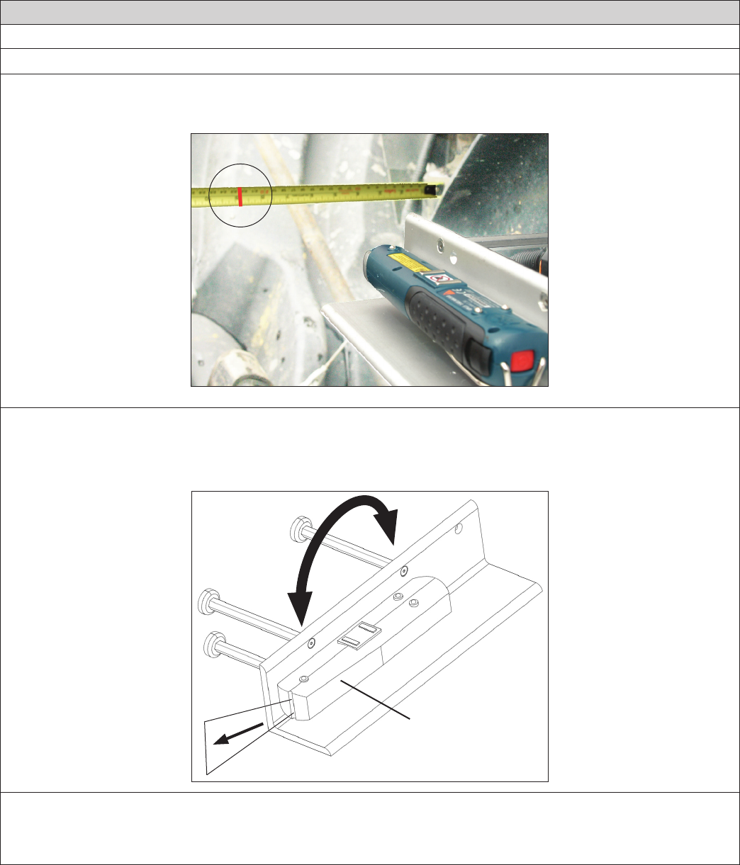
41
Appendix C
Bendix® FLR20™ Radar Alignment
LATERAL ALIGNMENT USING THE BENDIX® ALIGNMENT CLIP AND TOOL (CONTINUED)
C1.4 Locate symmetrical points on the front of the vehicle that are at least 12 inches from the vehicle’s center line
(such as the tow hooks). Using a ruler or tape measure, record the distance from each side to the laser light
line.
LATERAL ALIGNMENT LEFT MEASUREMENT
NOTE: The technician must be careful during the laser positioning process to double-check the values measured on each
side of the truck. Be sure to check back and forth for each side of the radar sensor several times to ensure accuracy.
C1.5 Repeat the process for the opposite side, reversing the tool, so that the laser light points to the other side of
the vehicle.
Lateral Alignment
Laser
Laser
Light Beam
The Whole
Tool is
Reversed for
the Second
Measurement
C1.6 Compare the left and right distance measurements. A properly aligned radar sensor will have the same
measurement from each side. If these two dimensions are within 1/8” (3 mm), no alignment is necessary and
the technician can go to Step C1.10 to check the vertical alignment. If an adjustment is needed, follow the
instructions in C1.7-9 on page 42
Appendix C
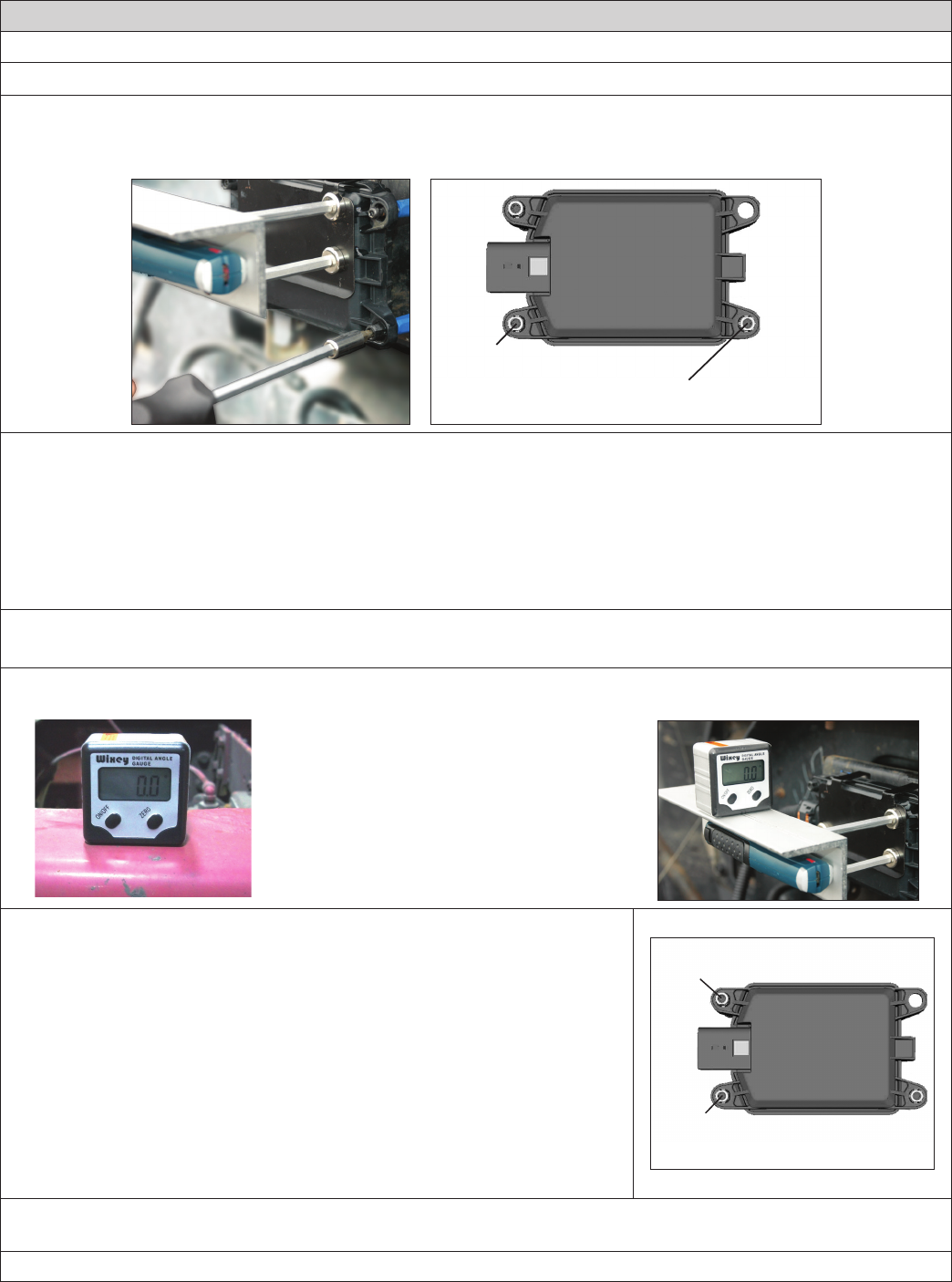
42
Appendix C
Bendix® FLR20™ Radar Alignment
C LATERAL ALIGNMENT USING THE BENDIX® ALIGNMENT CLIP AND TOOL (CONTINUED)
NOTE: Complete these steps only if a lateral adjustment is necessary.
C1.7 With the Bendix alignment tool still in place, use the Torx T-20 screwdriver to turn by hand the driver-side
stand-off adjustment screw until the desired alignment is reached
Use a Torx T-20 screwdriver here to
adjust for the lateral alignment
IMPORTANT:
Do not adjust
this stand-off!!
C1.8 Re-measure the distances from symmetrical points located at least 12” from the center line of the vehicle.
Reverse the tool for each measurement, until the values are the same [within 1/8” (3 mm)].
C1.9 After the lateral alignment procedure is complete, if there is an active misalignment DTC (codes 55, 56,
or 57), clear the Bendix® Wingman® Advanced™ system Diagnostic Trouble Code (DTC) using the procedure
in Section 4.4: Clearing Diagnostic Trouble Codes (DTCs) and reset the alignment value by connecting the
vehicle to a PC with Bendix® ACom® Diagnostics software and follow steps B4.4-20 to reset the alignment
value. (Also, see Appendix H.)
C1.10 IMPORTANT: Before returning the vehicle to service, check the vertical alignment.
C1.11 [The steel clip and alignment tool should already be in place. See C1.1-2.]
C1.12 Calibrate (or “zero”) the inclinometer on a horizontal section of the frame rail. Follow the manufacturer’s
instructions (typically digital inclinometers have a “SET” button for this purpose).
Calibrate (or “zero”) the Digital Inclinometer on a
Cab Frame Rail in the direction that the vehicle
travels.
Place the calibrated digital inclinometer onto the
surface of the tool, so that the tool is in the
same direction as it was on the rail. Verify
that the display shows 0° (± 1.5°) from vertical.
NOTE: Complete these steps only if a vertical adjustment is necessary.
C1.13 With the Bendix alignment tool still in place, use the screwdriver to turn
by hand the top-left adjustment stand-off. See the Figure on the right.
During the adjustment, observe the digital display on the inclinometer
and turn the vertical alignment screw clockwise or counterclockwise
depending on the vertical direction (up or down) needed, until the
reading is near zero degrees.
C1.14 The radar is aligned vertically when the display is near zero (0°).
Note: The alignment process shown here is for Bendix alignment
brackets. For other brackets, similar alignment steps will be needed;
consult the vehicle manual for full instructions.
Use a Torx T-20 screwdriver here to
adjust for the vertical alignment
IMPORTANT:
Do not adjust
this stand-off!!
NOTE: The alignment process is complete after the vertical alignment has been checked (and adjusted, if
necessary.) You do not need to test-drive the vehicle.
Call the Bendix Tech Team at 1-800-AIR-BRAKE (1-800-247-2725, option 2) for troubleshooting assistance.
Appendix C
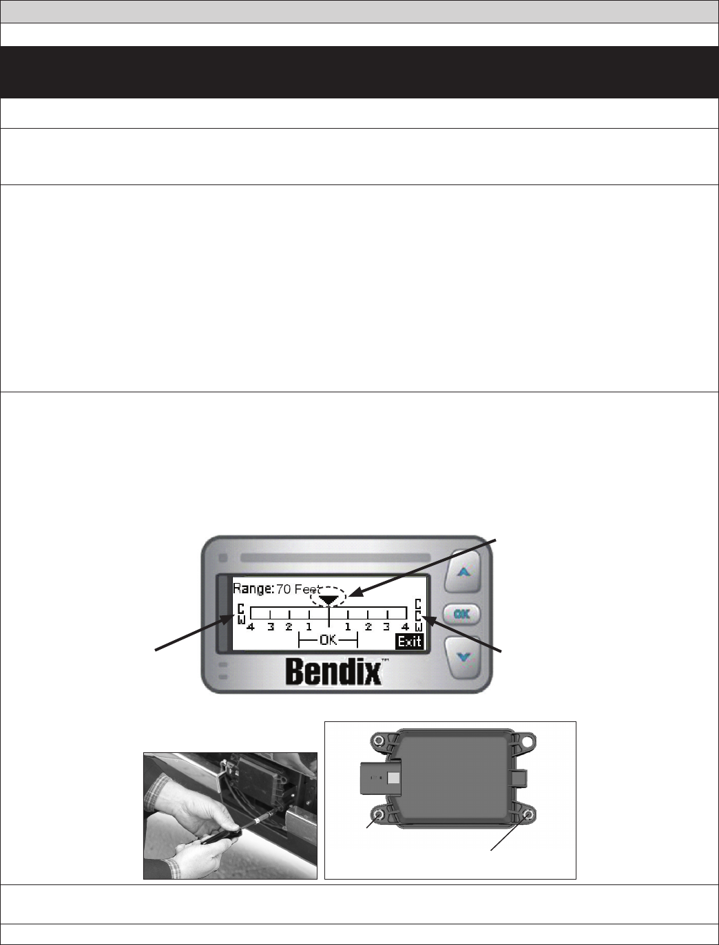
43
Appendix D
Bendix FLR20 Radar Dynamic Alignment Method
This procedure may be used in rare cases where the stored alignment value is not
available. The vehicle must have a DIU with a software version 12.220 or above.
LATERAL ALIGNMENT USING THE DYNAMIC ALIGNMENT METHOD
Use the owchart B1 to be sure you are using the correct alignment procedure. This procedure is used in
the rare cases where a learned alignment value is not available. For example, in cases where a technician
erroneously resets the alignment value before recording the Learned Alignment correction value and direction.
D1.1 Tools needed: DIU (with software version 12.220 or above), and a Torx T-20 Screwdriver. The assistance of
another vehicle will be necessary, and an assistant in the cab of the vehicle with the driver.
The DIU’s software version can be seen in the top right-hand corner of the Volume screen. The Bendix DIU’s
Dynamic Alignment Screen is used to show a dynamic calculation of the alignment of the radar.
D1.2 To perform the inspection, the vehicle must be traveling behind a cooperative vehicle on a straight, level length
of highway. Obeying all trafc laws, follow the vehicle in the same lane at a speed greater than 35 MPH.
For the most accurate results, the distance between the vehicles must be between 50 and 300 feet (15 to 91
meters), so the observed distance gure, displayed in the top left-hand corner of the display helps the driver
maintain the correct range. Verify that both vehicles remain in the middle of the lane during the test. The radar
determines the distance and alignment to the vehicle ahead, and, if needed, calculates an alignment correction
value, displayed on the screen.
D1.3 During the test, an assistant in the vehicle should observe where on the scale the triangle indicator shows the
alignment correction value. Because this is a dynamic measurement, the arrow will typically move through
a range of positions. Note the average position where the triangle points over a length of time. This value
gives the number of turns of the lateral adjust screw clockwise (CW) or counterclockwise (CCW), in order to
correct any misalignment present. See Figure below. The number of turns may require less than a full screw
turn, e.g. half way between 2 and 3 is 2.5 turns. The scale to the left of center shows when a clockwise (CW)
adjustment is needed, and numbers to the right are for counterclockwise (CCW) adjustments.
CW = Clockwise CCW = Counterclockwise
The indicator triangle will move
along the scale to show the
number and direction of turns to
make of the adjustment screw.
Dynamic Alignment Screen
Use a Torx T-20 screwdriver here to
adjust for the lateral alignment
IMPORTANT:
Do not adjust
this stand-off!!
D1.4 Alignment values less than 1.5 from the center are acceptable and do not necessarily require adjustment.
(See the “OK” zone shown on the scale for this range).
Call the Bendix Tech Team at 1-800-AIR-BRAKE (1-800-247-2725, option 2) for troubleshooting assistance.
Appendix D

44
Appendix E
Troubleshooting Checklist
Detailed Scenarios and Tests Record Driver’s Answers for
Follow-up with Bendix
Does the vehicle maintain its set speed when cruise control is switched on and
set? Yes No _____________
Is the cruise control “set” icon displayed? Yes No _____________
While following a forward vehicle within radar range and the cruise control
switched on and set, observe the following:
Is the forward vehicle detected icon displayed?
What color is the icon?
When the forward vehicle slows down, does the truck also slow down to
maintain the set distance?
Yes No _____________
Icon Color______________
Yes No _____________
With engine cruise “off” and a forward vehicle present, does the audible alert
become faster as the truck moves closer to the forward vehicle? Yes No _____________
With cruise control switched on and set, when the forward vehicle slows
moderately or cuts in front of the truck and slows, did you observe any of the
following conditions?
Does the vehicle slow and the Wingman Advanced system maintain the
following distance?
Is the engine throttle reduced?
Is the engine retarder applied?
Are foundation brakes applied?
Are there diagnostic trouble codes logged?
Does the truck proceed toward the forward vehicle without a following
distance alert or braking intervention?
Yes No _____________
Yes No _____________
Yes No _____________
Yes No _____________
Yes No _____________
Yes No _____________
With cruise control engaged, and while following a vehicle ahead in gentle
curves (assuming a 3 to 3.5 second following distance):
Does the Wingman Advanced system continue to follow the vehicle through
the curves following at a constant distance?
Does the truck proceed toward the forward vehicle without a following
distance alert or braking intervention?
Yes No _____________
Yes No _____________
With cruise engaged, when your vehicle passes a slower vehicle on the left or
right on a straight or slightly curvy road:
Does Wingman Advanced ignore the vehicle you are overtaking?
Does it give a following distance alert?
Yes No _____________
Yes No _____________
APPENDIX E - TROUBLESHOOTING CHECKLIST
Appendix EAppendix E
45
Appendix E
Troubleshooting Checklist
Detailed Scenarios and Tests Record Driver’s Answers for
Follow-up with Bendix
With cruise engaged, and a faster vehicle passes your vehicle on the left or
right on a straight or slightly curvy road:
Does your vehicle throttle up and try to keep pace with the faster moving
vehicle?
Does it give a following distance alert?
Yes No _____________
Yes No _____________
With cruise control engaged, if the vehicle ahead slows moderately or cuts in
front of your truck and slows down:
Does your vehicle slow and the Wingman Advanced system maintain the
following distance?
Is the engine throttle reduced?
Is the engine retarder applied?
Are the foundation brakes applied?
Are there diagnostic trouble codes logged?
Does your truck proceed toward the forward vehicle without a following
distance alert or braking intervention?
Yes No _____________
Yes No _____________
Yes No _____________
Yes No _____________
Yes No _____________
Yes No _____________
What version of Bendix® ABS and Bendix® Wingman® Advanced™ is installed on
the vehicle? See Section 4.21: Reading the Advanced Software Version. ___________________________
What are the key system indicators?
See Section 5.1: System Key Indicators.
___________________________
___________________________
___________________________
___________________________
___________________________
Call the Bendix Tech Team at 1-800-AIR-BRAKE (1-800-247-2725, option 2)
(Monday–Friday, 8:00 a.m. – 6:00 p.m. ET) for troubleshooting assistance.
Appendix E
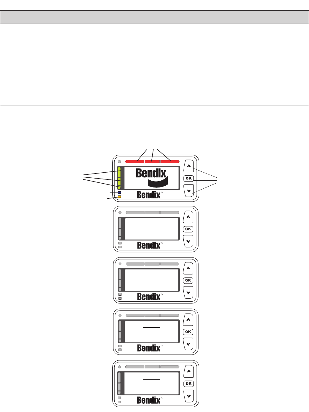
46
Appendix F
Bendix® Driver Interface Unit (DIU): Displays & Alerts
F1 Operator Interface
The Bendix® Wingman® Advanced™ system is either integrated into the vehicle's dash or console, or uses the
Bendix® Driver Interface Unit (DIU) to communicate with the driver. (For integrated systems, see the vehicle
operator’s manual for more information.)
This Section describes the functions of the DIU. The DIU mounts in, or on, the vehicle dash and provides the
interface between the driver and the Advanced system. The DIU provides visual and audio warnings to the
driver and accepts input from the driver through the “Up”, “Down” and “OK” buttons.
The DIU contains an internal speaker to provide audible warnings, 2 LED arrays (one each in yellow and red),
a single orange and blue LED and an LCD screen for visual warnings, and a light radar sensor to distinguish
between day and night conditions.
F1.1 Start-Up Mode
At initialization, the DIU executes self-test routines during which the following screens are displayed and all
LEDs are activated (power-on bulb check) for approximately 3 seconds. If congured, a power-up tone is
also sounded.
APPENDIX F - DRIVER INTERFACE UNIT (DIU): DISPLAYS AND ALERTS
Appendix F
Buttons
Wingman®
Advanced
A Collision Mitigation
Technology by
Bendix
NOTE:
Wingman® Advanced
Uses Foundation Brakes
NOTE:
Read Operator's Manual
before using
Three Red LEDs
Illuminated
Single Blue
LED Illuminated
Single Orange
LED Illuminated
All Yellow LEDs
Illuminated
(No LEDs
Illuminated)
(No LEDs
Illuminated)
(No LEDs
Illuminated)
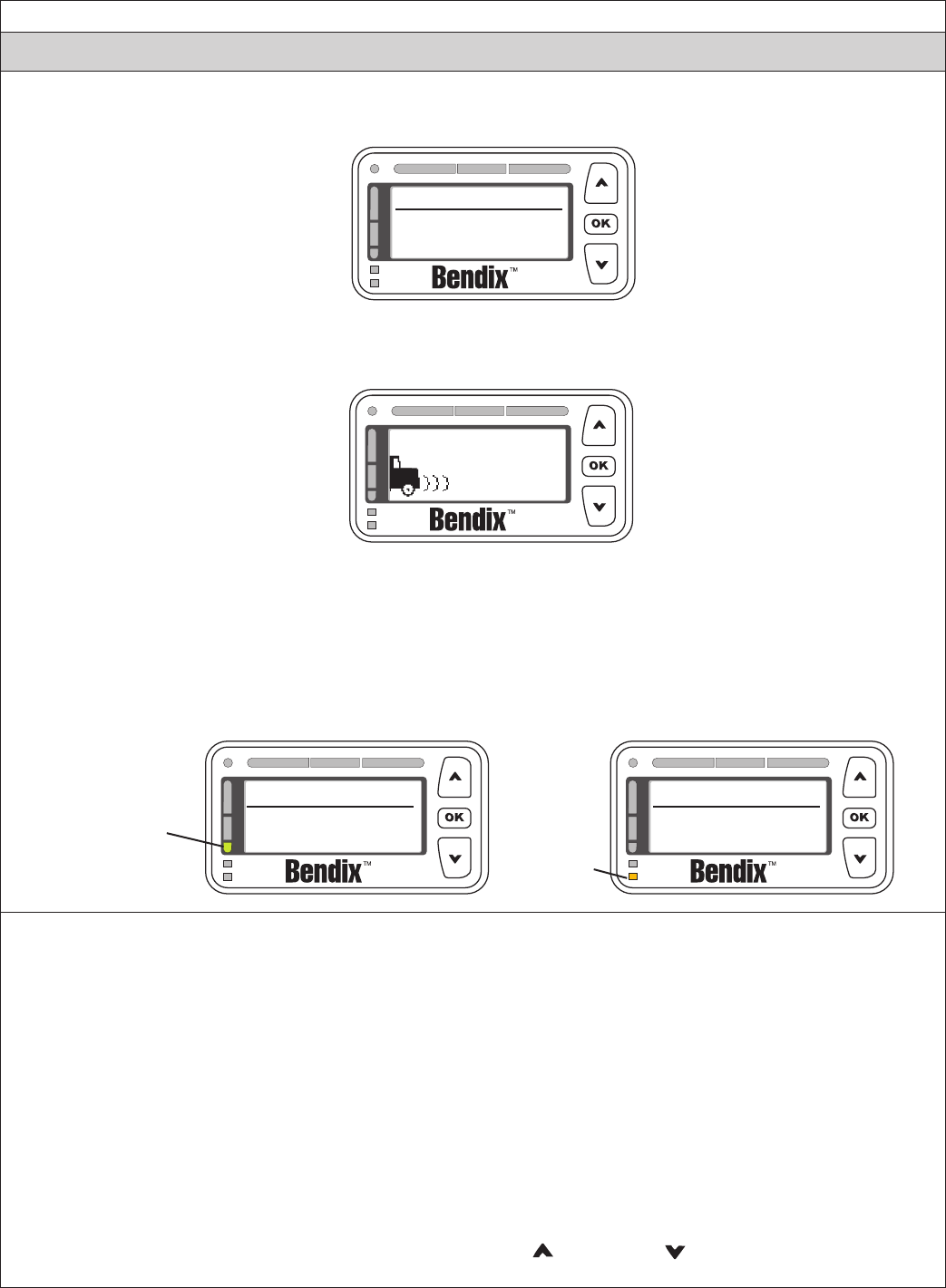
47
Appendix F
Bendix® Driver Interface Unit (DIU): Displays & Alerts
When the initialization sequence is complete, the following screen is displayed for approximately 3 seconds
to indicate the features available to the driver.
(No LEDs
Illuminated)
Bendix
Wingman ACB
Wingman Adv.
Next, the DIU will enter normal operation. Under normal operation, the screen is:
(No LEDs
Illuminated)
If the Bendix® Wingman® Advanced™ goes into self-test mode, the DIU may briey display the “Bendix Self-
Test” screen. Also, the audible distance alerts will activate, followed by a screen indicating that the self-test
has run. Below left is the screen that will be briey displayed if the self-test runs and passes. Below right is
the screen that will be briey displayed if the self-test runs and fails. If the self-test fails, a diagnostic trouble
code (DTC) will be set. The driver should turn off the vehicle, wait 15 seconds and then turn it back on again.
If the problem persists, a qualied technician will be necessary for troubleshooting. See the “Power-Up Self-
Test” in this service data sheet Section 3.1: Troubleshooting Basics for further information.
Bendix
Self Test
Bendix
Self Test Failed
Single Yellow LED
Illuminated
(Followed
by a Single
Orange
LED
Illuminated)
F1.2 Menu Operation
Pressing the “OK” button at any time will enter the “Menu Operation Mode”. The following selections will
appear in a scrollable window. Some items may not appear if the feature is not congured or not allowed as
shown below.
• Volume
• Radar
• Dist. Setting (Distance Setting)
• Dist. Units (Distance Units)
• US/Metric
• Object Speed
• Brightness
• System Status
• Diag. Display (Diagnostic Display)
• Demo (Demonstration. Note: Demo is available only when vehicle is not moving)
The desired menu item is highlighted using the up ( ) or down ( ) arrow buttons and selected
with the “OK” button. The following sections describe each menu item.
Appendix F
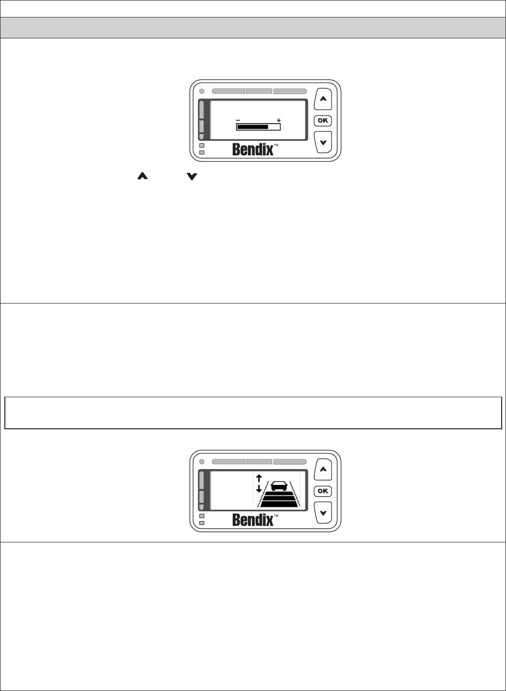
48
Appendix F
Bendix® Driver Interface Unit (DIU): Displays & Alerts
F1.3 Volume
Selecting “Volume” from the main menu displays the following screen:
Volume
The driver uses the up ( )/down ( ) arrow buttons to change the volume. Pressing the “OK” button exits
this menu item.
The modied volume setting will be retained through ignition cycles unless congured not to do so. If not
congured, the volume setting will default to 100% on each new ignition cycle.
NOTE: The DIU can be congured to limit the minimum volume setting that the driver can select. The bar
shown above always represents the adjustable range based on minimum and maximum values. For example,
if the minimum value is set to 50% (midpoint between lowest (70 +/- 3dB) and highest (89 +/- 3dB) audio
levels, the bar represents an adjustable range from 50% (approx. 80dB) to 100% (approx. 89dB). Once the
minimum (or maximum) has been reached, a message will be shown indicating that further adjustment is not
allowed (e.g. “Minimum volume reached”). The step change per button press is approximately 2dB.
F1.4 Distance Setting (Dist. Setting)
On systems where changes are permitted, the “Distance Setting” option from the main menu will adjust the
following distance that the Bendix® Wingman® Advanced™ system will attempt to maintain while in the following
distance mode. Distance Settings 1, 2, 3, and 4 will have different meanings based on the conguration chosen
by the user in Bendix® ACom® Diagnostics software. Generally, 4 relates to the farthest distance setting available
and 1 relates to the closest distance setting available. In many of the Advanced congurations available in ACom®,
two or more distance settings may be made equivalent to one another.
Selecting “Dist. Setting” from the main menu displays the following screen:
Text
Here*
F1.5 Distance Units (Dist. Units)
From the “Dist. Units” menu item, the user may choose to have the following distance from the forward vehicle
displayed in either seconds or feet. By default, this item is set to seconds. If the user selects feet, the DIU will
display the approximate distance from the bumper to the selected forward vehicle in feet. If the user selects
seconds, the DIU will display the approximate distance from the bumper to the selected forward vehicle in
seconds.
NOTE: Following distance in seconds is calculated based on the current speed of the Wingman®
Advanced-equipped truck, and the distance, in feet, away from the selected forward vehicle. For instance, if
the selected forward vehicle is 88 feet from the bumper of the Wingman Advanced-equipped truck, and the
Wingman Advanced-equipped truck is traveling 60 mph, then the following distance in seconds would be 1.0
seconds because a truck traveling 60 mph can travel 88 feet in one (1) second.
(No LEDs
Illuminated)
(No LEDs
Illuminated)
Appendix F
For more information on user congurations available through the Bendix ACom Diagnostics software, see
Section 5.4: Conguring Bendix Wingman Advanced Following Distance Alerts in this Service Data sheet for further information.
* Text may vary
depending on the
system installed
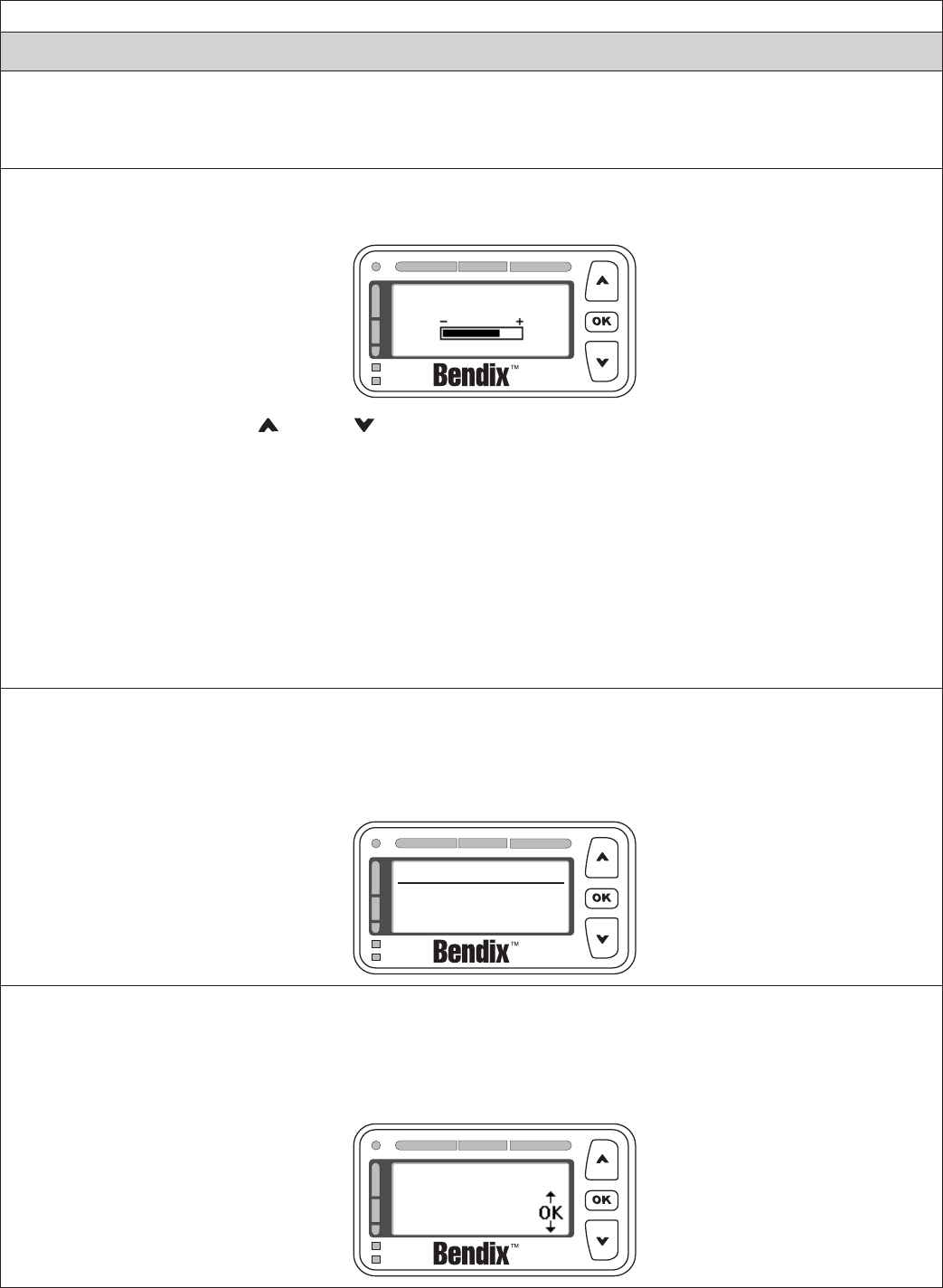
49
Appendix F
Bendix® Driver Interface Unit (DIU): Displays & Alerts
F1.6 US/Metric
From this menu item, the user may select whether English or Metric units are displayed. For instance, in
“metric” mode, the following distance is shown in meters. In “US” mode, the following distance is shown in feet.
F1.7 Brightness
Selecting Brightness from the main menu displays the following screen:
Brightness
The driver uses the up ( )/down ( ) arrow buttons to change the LCD backlighting, LED brightness and
button backlighting. Pressing the OK button exits this menu item.
The light sensor reading determines whether the current cab lighting mode is bright (day) or dark (night).
When the light mode is bright, any brightness adjustment made by the driver is applied to only the bright
mode setting. Likewise, when the light radar sensor sets the light mode to dark, any brightness adjustment
made by the driver is applied to only the dark mode setting. This functionality allows the driver to adjust the
brightness setting for the two cab lighting conditions after which the DIU will automatically toggle between the
two settings based on the light radar sensor’s input. Both the bright mode setting and the dark mode setting
are stored across power cycles.
NOTE: The DIU does not allow the brightness control to completely shut off the LEDs.
F1.8 System Status
This screen shows the congured features of the system and their current operational status (i.e., “Failed”
or “OK”). The failed status means that some system malfunction is preventing the feature from properly
operating and that the feature is not available for use by the driver at this time. Pressing “OK” exits this menu
item.
Bendix
Wingman ACB OK
Wingman Adv. OK
F1.9 Diagnostics
Selecting Diagnostics from the main menu displays any active Bendix® Wingman® Advanced™ Diagnostic
Trouble Code (DTC) conditions [including SAE standard diagnostic codes called J1939 SPNs (Suspect
Parameter Numbers) and J1939 FMIs (Failure Mode Identiers)] that may be present in the DIU and radar
sensor. The following is a typical screen displayed in this mode when an active DTC is present:
DIU DIAGNOSTICS
SPN:00886 FMI:012
(No LEDs
Illuminated)
(No LEDs
Illuminated)
(No LEDs
Illuminated)
Appendix F

50
Appendix F
Bendix® Driver Interface Unit (DIU): Displays & Alerts
F2.0 Driver Demonstration Mode
Selecting Demo from the main menu starts a demonstration mode that shows the various lights, display
screens, and sounds produced by the DIU – along with a brief explanation of their meaning – for the congured
features. Pressing the down ( ) arrow button advances through the screens. The up ( ) arrow button has
no functionality in this mode. The mode may be exited at any time by pressing the OK button.
NOTE: This mode can only be entered while the vehicle is not moving. Also, while in the demonstration
mode, if the vehicle begins to move, the demonstration mode terminates.
If a screen is associated only with a congurable feature, and that feature is not congured, then that screen
will not be shown in the demonstration mode.
The screens presented to the driver in the demonstration mode are shown with the following text: “Error!
Reference source not found.”
F3.0 Following Distance Alerts (FDAs)
One of the features of the Bendix® Wingman® Advanced™ system is the Following Distance Alert (FDA). A
proprietary system combining vehicle speed, forward vehicle speed, distance, and driving scenario, FDAs are
used to provide the driver with distance alerts which are intelligent, in that they will give appropriate distance
alerts for the given situation. They alert the driver to objects far ahead in highway and country road driving
situations while not over-alerting in dense city trafc.
The radar sensor uses the DIU to communicate the FDA alerts to the driver. This system can be congured
through a current version of Bendix® ACom® Diagnostics software, for use by a eet as a driver training tool
with or without coordinating the data made available by Wingman Advanced. In addition to being a reminder
of when a driver may be dangerously close to the vehicle ahead, the following distance alerts may also be
congured to reinforce safe following distance habits taught by the eet.
The FDA is based on the following interval between the host vehicle and the object ahead. In other words,
this is the time required by the host vehicle to travel forward and reach the object’s current location. With the
exception of the volume, the FDA may not be adjusted by the driver through the DIU. A qualied technician
must connect to the vehicle through the diagnostic port and run ACom® Diagnostics, in order to change the
conguration. The volume can not be turned all the way down, but other adjustments may be made by the
eet. See Section B1.3 for more details on volume adjustment.
The FDA system is intended only to alert the driver about following distance. For more information on alerts
for forward objects with high relative velocities and sudden decelerations, see Section B4.0: Impact Alert.
Only objects detected in the vehicle's lane, traveling in the same direction, are considered valid objects for the
FDA. For more information on stationary objects, see Section B5.0: Stationary Object Alert.
See Section 5.4: Conguring Bendix Wingman Advanced Following Distance Alerts.
Appendix F
The driver is always responsible for the control and
safe operation of the vehicle at all times. The Bendix®
Wingman® Advanced™ system does not replace the
need for a skilled, alert professional driver, reacting
appropriately and in a timely manner, and using safe
driving practices.
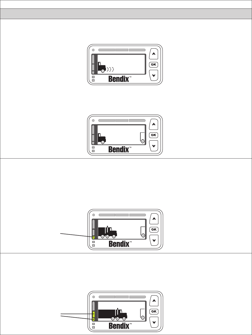
51
Appendix F
Bendix® Driver Interface Unit (DIU): Displays & Alerts
F3.1 Object Detected
When there is no valid object detected and no other high priority alert is displayed, the DIU will stand by with
the following screen:
When a valid object is detected, and is outside the range of the rst level of alert, and no other higher priority
alert is displayed, the DIU will display the following and no audio tones will be issued. The distance to the
object will be displayed in large characters in the white space at the center of the screen (not shown) in
seconds, feet, or meters, depending on the menu-selected preferences. By default, seconds will be displayed.
Object Detected
55
mph
sec
2.8
F3.2 Following Distance Alert (FDA) Level 1 (Slow audible two-tone alert/single LED illuminated)
When FDA Level 1 is issued, the following distance to the object/vehicle ahead has been reduced to the
distance determined in the current conguration for FDA Level 1. The DIU will begin to give the driver audio
and visual alerts for as long as the forward vehicle is in this zone and traveling at the same speed or slower.
The DIU will not display following distance units while in an FDA Level. For FDA Level 1, the audible alert will
be a single repeating tone, and the visual alert is a single yellow LED and a screen with the vehicles slightly
closer as shown below.
Object Detected
Single Yellow LED
Illuminated
F3.3 Following Distance Alert (FDA) Level 2 (Medium audible two-tone alert/two LED’s illuminated)
The DIU will give the driver audio and visual alerts for as long as the object/vehicle ahead is in this zone and
traveling at the same speed or slower. The DIU will not display following distance while in an FDA Level. For
FDA Level 2, the audible alert will be a repeating double tone, and the visual alert is two yellow LEDs and a
screen with the vehicles closer as shown below.
Object Detected
Two Yellow LEDs
Illuminated
(No LEDs
Illuminated)
(No LEDs
Illuminated)
Appendix F
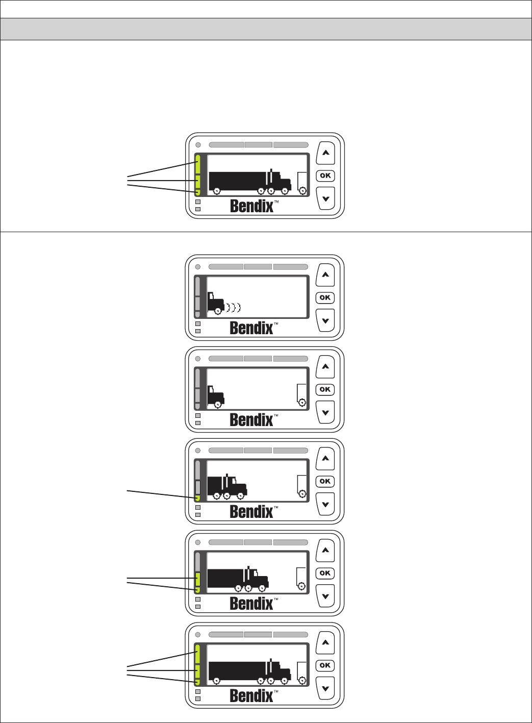
52
Appendix F
Bendix® Driver Interface Unit (DIU): Displays & Alerts
F3.4 Following Distance Alert (FDA) Level 3 (Fast audible two-tone alert/three yellow LEDs illuminated)
The DIU provides the driver with audio and visual alerts for as long as the vehicle ahead is in this zone and
traveling at the same speed or slower. This is the closest and most urgent Following Distance Alert.
The DIU will not display following distance while in an FDA Level. For FDA Level 3, the audible alert will be
a continuously repeating tone, and the visual alert is three yellow LEDs and a screen with the vehicles close
as shown below:
Object Detected
All Yellow LEDs
Illuminated
All ve states of the FDA system can be seen together below.
Object Detected
Object Detected
Object Detected
Object Detected
FDA Level 1:
Single Yellow
LED Illuminated
FDA Level 2:
Two Yellow
LEDs Illuminated
FDA Level 3:
All Yellow LEDs
Illuminated
(No LEDs
Illuminated)
(No LEDs
Illuminated)
Appendix F
(No Tone)
(No Tone)
(Single Repeating
Double Tone)
(Repeating
Double Tone)
(Continuously
Repeating Tone)
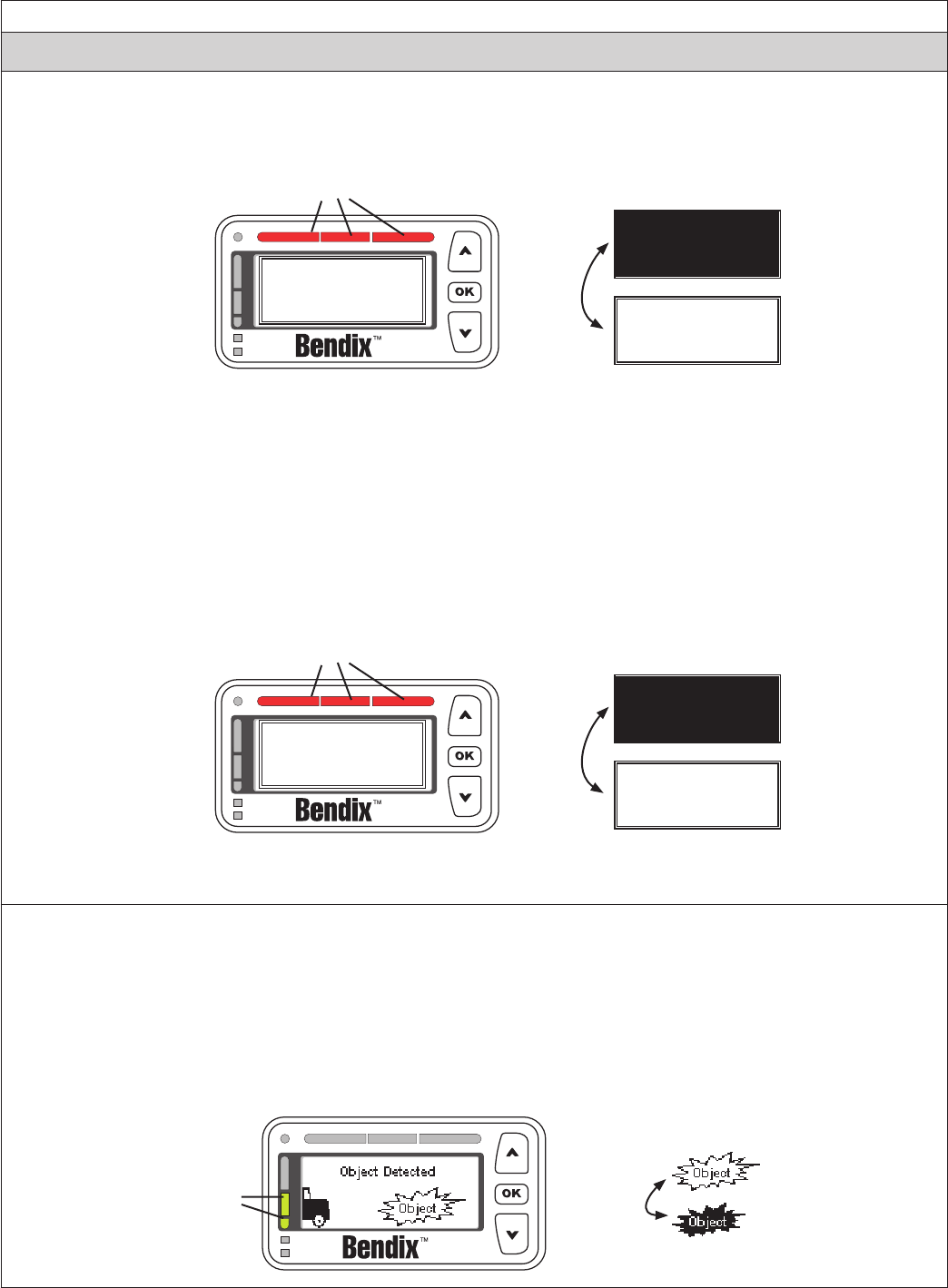
53
Appendix F
Bendix® Driver Interface Unit (DIU): Displays & Alerts
F4.0 Impact Alert (IA)
The “Impact Alert”, uses a combination of distance to the vehicle ahead, plus high relative velocity, to decide when
to issue a loud solid tone, as well as a visual indicator to the driver. The red LED bar across the top of the DIU will
illuminate and “ACB Requires DRIVER INTERVENTION” will ash using the two screens below:
Screen
ashes
between
these two
displays
ACB REQUIRES
DRIVER INTERVENTION
ACB REQUIRES
DRIVER INTERVENTION
All Red LEDs Illuminated
ACB REQUIRES
DRIVER INTERVENTION
When the Impact Alert activates, the driver must immediately act to potentially avoid, or lessen the severity
of, a collision.
The impact alert can not be congured or turned off.
NOTE: At most, the adaptive cruise control with braking feature of Bendix® Wingman® Advanced™ will apply
up to one-third of the vehicle’s braking capacity. The driver must apply additional braking, when necessary,
in order to maintain a safe distance from the vehicle ahead.
F4.1 Collision Mitigation
If a collision is likely to occur, and the collision mitigation feature activates the foundation brakes, the tone
of the alert will typically change and the display will be as shown below. The driver must immediately act to
potentially avoid, or lessen the severity of, a collision.
Screen
ashes
between
these two
displays
WINGMAN Adv.
BRAKING
WINGMAN Adv.
BRAKING
All Red LEDs Illuminated
WINGMAN Adv.
BRAKING
NOTE: At most, the collision mitigation feature of Bendix® Wingman® Advanced™ will apply up to two-thirds
of the vehicle’s braking capacity.
F5.0 Stationary Object Alert (SOA)
Stationary Object Alert (SOA) is an alert given to the driver when the radar detects a sizeable, nonmoving
metallic object in the vehicle's path of travel. To reduce the number of false detections, such as bridges and
overhead signs, an advanced set of lters are put in place so the SOA will not warn on every stationary object.
The SOA can be congured to be on or off through Bendix® ACom® Diagnostics.
If a SOA is issued, the DIU will very briey send out an alert identical to a very brief FDA Level 2: continuous
tone and two yellow LEDs, with the display image switching between the two shown below.
“Object” icon
ashes
between
these two
symbols
Two
Yellow
LEDs
Illuminated
Appendix F
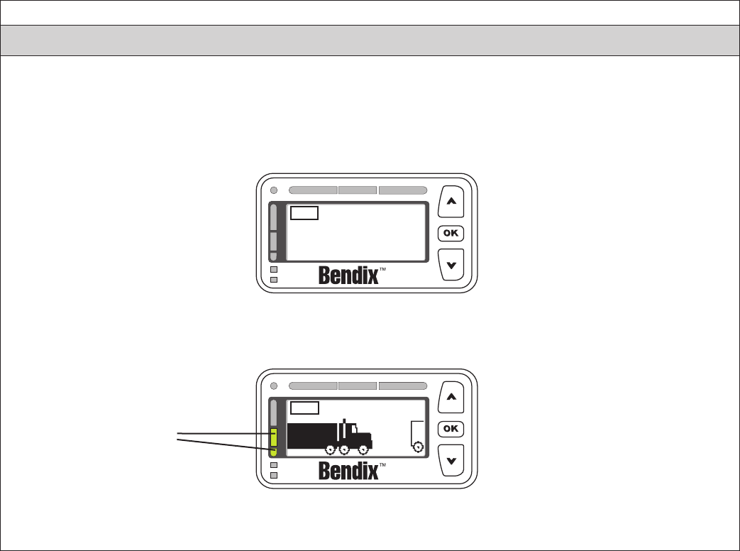
54
Appendix F
Bendix® Driver Interface Unit (DIU): Displays & Alerts
F6.0 ACB Icon
The ACB icon appears in the upper left-hand corner of the DIU’s screen to indicate to the driver that the
adaptive cruise control with braking feature of the Bendix® Wingman® Advanced™ system is ready and able
to intervene.
Once the driver sets cruise, the DIU will display the set speed and the ACB icon as shown below.
Set
Speed 55 mph
ACB
When a forward vehicle is detected and either the distance to the vehicle or a following distance alert is
shown, the ACB icon should remain on the screen if the adaptive cruise control feature of Wingman Advanced
is still engaged and ready to intervene.
Object Detected
ACB
Two Yellow LEDs
Illuminated
NOTE: If the ACB icon is not displayed on the screen, the driver must assume that the
adaptive cruise control with braking feature of Wingman Advanced is not ready or able to intervene!
(No LEDs
Illuminated)
Appendix F

55
Appendix F
Bendix® Driver Interface Unit (DIU): Displays & Alerts
F7.0 Brake Overuse Alert
Using cruise control on downhill runs is the primary cause for this alert to be activated. Cruise control should
NOT be used on downhill grades. Approach grades as you would normally, with the appropriate gear selected
and at a safe speed.
To guard against foundation brake overuse by the adaptive cruise control with braking feature of the Bendix® Wingman®
Advanced™ system, the frequency of foundation brake interventions is monitored. If the system detects a situation
where the brakes are being applied too frequently by the system in a given time period, the brake overuse alert will
activate. This is designed to help prevent overheating of the brakes, which may lead to brake fade and reduced vehicle
braking capability. In this situation, the Brake Overuse Alert will ash a message requesting driver intervention. Also, an
audible alert will sound and a blue LED will blink on the Bendix Driver Interface Unit (DIU), as illustrated below:
Screen
ashes
between
these two
displays
ACB REQUIRES
DRIVER INTERVENTION
ACB REQUIRES
DRIVER INTERVENTION
Blue
LED
Blinks
ACB REQUIRES
DRIVER INTERVENTION
This alert will continue for 15 seconds, during which time the driver should step on the brake or turn off cruise
control using the cruise control on/off switch.
If the system
detects that
the driver has
intervened
within 15
seconds after a
brake overuse
alert
(Typically by
applying the
brakes, or
cancelling cruise
control)
• The intervention cancels cruise control.
• After a Brake Overuse Alert, for a period of time (typically 20 minutes), the Wingman
Advanced system will not use the foundation brakes when intervening. The system
will be limited to de-throttling the engine and applying the engine retarder during this time.
Note: In all cases, the driver still has the ability to apply the foundation brakes if
necessary. The driver should take care since overheated brakes may reduce the
vehicle’s braking capability.
• The time period for this mode is measured from the time the Brake Overuse Alert was
activated and lasts approximately 20 minutes.
• Note: The driver will continue to receive all three alerts (FDA, Impact, and Stationary Object).
• Additionally, the DIU message will change to “ACB Braking Overuse” and the blue LED will
remain lit, as shown below:
Blue LED
Stays On
Bendix
_____________________
ACB BRAKING OVERUSE
Press OK for Menu
At the end of the
“cooling-off” period, the
“ACB Braking Overuse”
message and the blue
LED will turn off.
If the system
does not detect
an intervention
by the driver
within 15
seconds after a
brake overuse
alert
• The system will shut itself off, and set a Diagnostic Trouble Code (DTC).
• All intervention features of Wingman Advanced will be disabled until the next ignition
cycle.
• Note: The driver will continue to receive all three alerts (FDA, Impact, and Stationary Object).
• Note: In all cases, the driver still has the ability to apply the foundation brakes if
necessary. The driver should take care since overheated brakes may reduce the
vehicle’s braking capability.
Appendix F
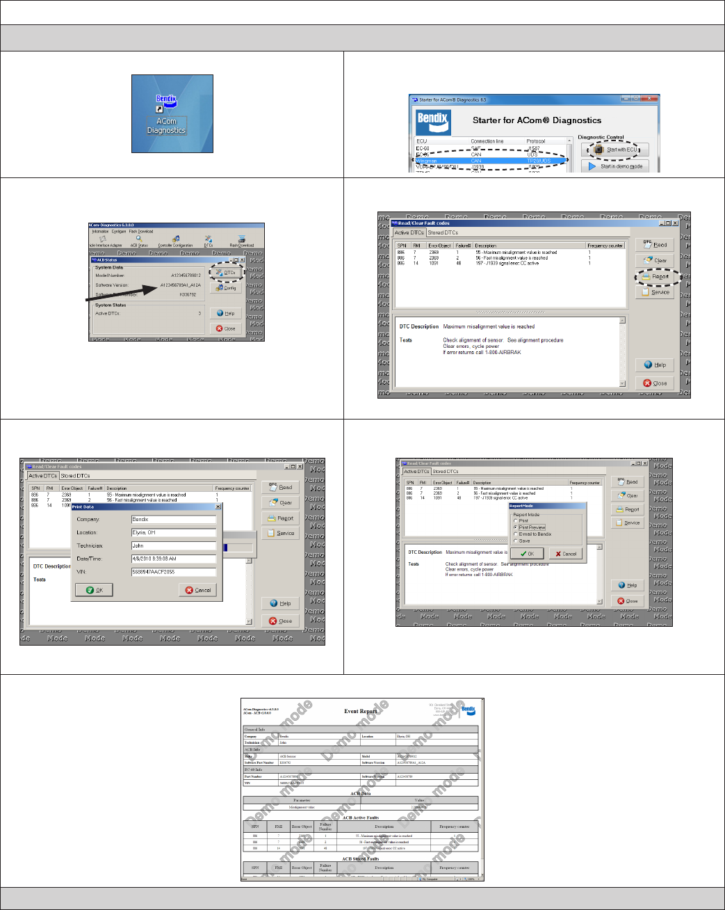
56
Appendix G
G1: How to Generate Wingman® Diagnostic Trouble Code Report with ACom® Diagnostics
1. Select the Bendix® ACom® desktop icon 2. Select “Wingman” from the starter screen. Select “start with
ECU”
3. Select “DTC”.
For reference
4. To generate the ACom report, select “Report”.
5. Fill in the requested information: Company, location,
technician, date/time, VIN, and click “OK”
6. Select how you want the report displayed or printed. Then click
“OK”
7. The ACom DTC report is generated. This can be saved and emailed to Bendix if desired.
Call the Bendix Tech Team at 1-800-AIR-BRAKE (1-800-247-2725, option 2) for troubleshooting assistance.
APPENDIX G - HOW TO GENERATE, READ AND RESET THE BENDIX® WINGMAN® SYSTEM
DIAGNOSTIC TROUBLE CODES USING BENDIX® ACOM® DIAGNOSTICS SOFTWARE
Appendix G-
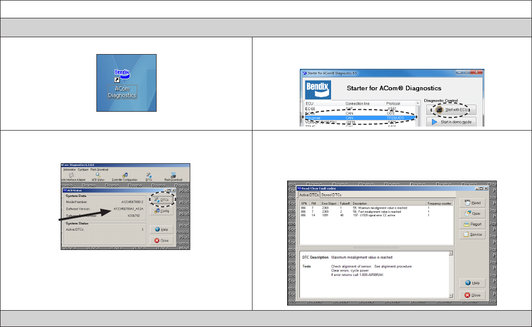
57
Appendix G
G2: How to Read Wingman® Diagnostic Trouble Code Reports with Bendix® ACom® Diagnostics
1. Select the Bendix® ACom® desktop icon 2. Select “Wingman” from the starter screen. Click “start with
ECU”
3. Select “DTC”.
For reference
4. Select "Read". Active DTCs (diagnostic trouble codes) are
shown along with descriptions of the codes and tests that can
be run to troubleshoot the code. You can select “stored DTCs”
also, to show inactive DTCs.
Call the Bendix Tech Team at 1-800-AIR-BRAKE (1-800-247-2725, option 2) for troubleshooting assistance.
Appendix G-
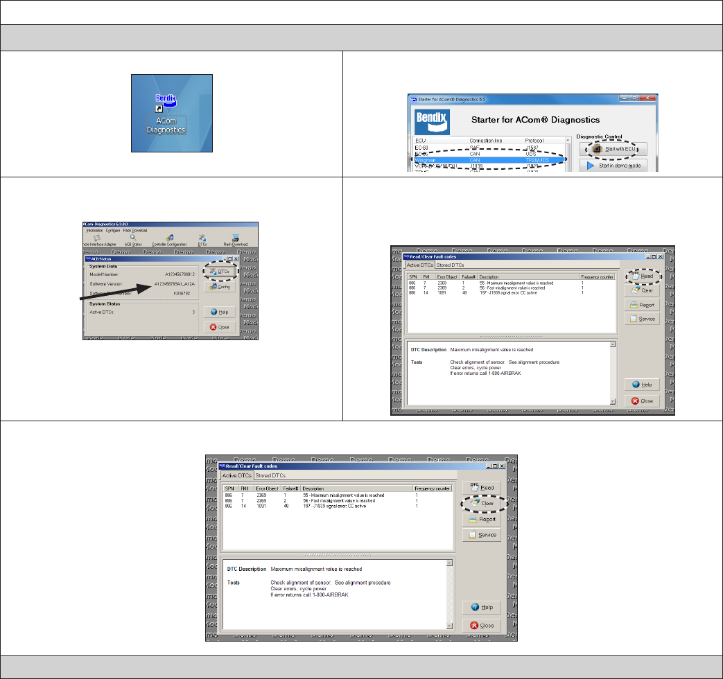
58
Appendix G
G3: How to Clear Wingman® Diagnostic Trouble Codes with Bendix® ACom® Diagnostics
1. Select the Bendix® ACom® Diagnostics desktop icon 2. Select “Wingman” from the starter screen. Select “start with
ECU”
3. Select “DTC”.
For reference
4. Click "Read". Active DTCs (diagnostic trouble codes) are
shown along with descriptions of the codes and tests that can
be run to troubleshoot the code. You can select “stored DTCs”
also, to show inactive DTCs.
5. Select “clear” to clear all active DTCs.
Call the Bendix Tech Team at 1-800-AIR-BRAKE (1-800-247-2725, option 2) for troubleshooting assistance.
Appendix G-
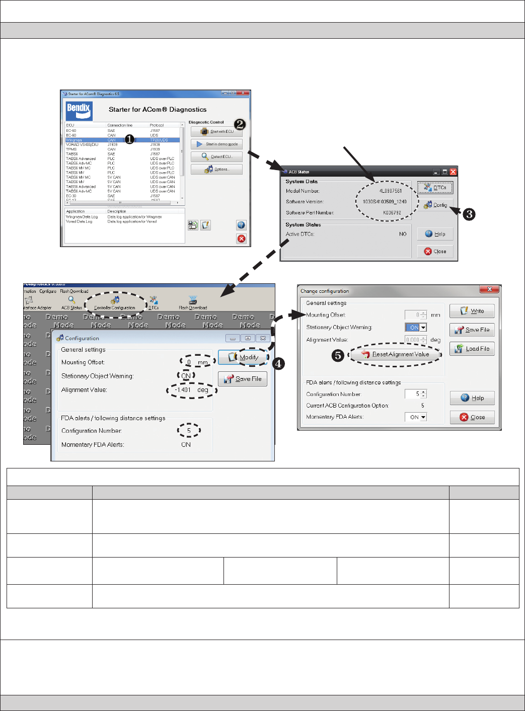
59
Appendix H
Appendix H
How to Read Key System Indicators and Reset Alignment Values
Read System Key Indicators (Conguration)
1. Start Bendix® ACom® Diagnostics and connect to vehicle.
2. Select “Advanced” and Click “Start with ECU” to display the “Advanced Status” window.
3. Select “Cong” to display the indicators
Take Note of:
Model #,
Software Version,
Software P/N,
Active DTCs
System Key Indicators
Attribute Description See Section:
Mounting Offset
This value should equal 0 if the radar sensor is mounted on the center line of the vehicle.
If the service technician believes the radar sensor should be mounted offset from center,
call 1-800-AIR-BRAKE (1-800-247-2725, option 2).
6.2
Stationary Object
Warning Indicator
This is a status indicator for the function of stationary object warning. Available for use
in Bendix® Wingman® Advanced™ system versions since 2010. 1.7
Lateral Alignment
Value
Trouble code will be set if
value is less than -1.5º
Normal operation
-1.5º to 1.5º
Trouble code will be set if
value is more than 1.5º 6.8
Conguration
Number
This indicates the distance setting and following distance alert that are congured for
the vehicle. Refer to Table 7 for setting information. 5.4
How To Reset The (Lateral) “Alignment Value”
4. From the conguration window shown above, click “Modify.”
5. From the Change Conguration window, select “Reset Alignment Value.”
6. Cycle the vehicle ignition power to complete the process.
Call the Bendix Tech Team at 1-800-AIR-BRAKE (1-800-247-2725, option 2) for troubleshooting assistance.
60
Full Contents List
1.0 Operation Section
1.1 Important Safety Information. . . . . . . . . . . . . . . . . . . . 3
1.2 System Components. . . . . . . . . . . . . . . . . . . . . . . . 4
1.3 Activating the Bendix® Wingman® Advanced™ System . . . . . . 4
1.4 What to Expect When Using Bendix Wingman Advanced . . . . 5-6
1.5 How a Driver Interacts with Bendix Wingman Advanced . . . . . 7
1.6 Following Distance . . . . . . . . . . . . . . . . . . . . . . . . . 8
1.7 Wingman Advanced Collision Mitigation Feature Operation . . . . 8
1.8 Alerts and Warnings . . . . . . . . . . . . . . . . . . . . . . 8-10
1.9 Wingman Advanced Diagnostic Trouble Codes . . . . . . . . . 10
1.10 Radar Sensor Interchangeability. . . . . . . . . . . . . . . . . 10
1.11 Alert Volume . . . . . . . . . . . . . . . . . . . . . . . . . . . 10
1.12 Potential False Warnings . . . . . . . . . . . . . . . . . . . . 10
2.0 Maintenance Section
2.1 General Safety Guidelines . . . . . . . . . . . . . . . . . . . . 11
2.2 Equipment Maintenance: Brake System and ABS Functionality. 12
2.3 System Preventive Maintenance. . . . . . . . . . . . . . . . . 12
2.4 Additional Support at www.bendix.com/1-800-AIR-BRAKE (1-800-247-2725,
option 2) . . . . . . . . . . . . . . . . . . . . . . . . . . . . . . . . . 12
3.0 Introduction to Troubleshooting Section
3.1 Troubleshooting Basics . . . . . . . . . . . . . . . . . . . . . 13
3.2 Narrowing Down the Problem . . . . . . . . . . . . . . . . . 14-15
3.3 Overview of Possible Issues . . . . . . . . . . . . . . . . . . . 16
4.0 Troubleshooting/Diagnostics Section
4.1 Bendix® ACom® Diagnostics Software . . . . . . . . . . . . . . 17
4.2 Reading Diagnostic Trouble Codes (DTCs) . . . . . . . . . . . 18
4.21 Reading the System Software Version. . . . . . . . . . . . . . 18
4.3 Diagnostic Trouble Codes (DTCs) - Tables 6A and 6B . . . . 19-25
4.4 Clearing Diagnostic Trouble Codes (DTCs) . . . . . . . . . . . 26
4.5 Troubleshooting Diagnostic Trouble Codes: Power Supply . . . 26
4.6 Serial Data (J1939) Communications Link. . . . . . . . . . . . 26
4.7 Engine Communications (J1939) Test Procedure . . . . . . . . 27
4.8 Troubleshooting Wiring Harnesses . . . . . . . . . . . . . . . 27
61
NOTES
5.0 Other System Features Section
5.1 Reading Bendix® Wingman® Advanced™ System Key Indicators 28
5.2 Bendix Wingman Advanced Diagnostic Trouble Code (DTC)
Self Clearing . . . . . . . . . . . . . . . . . . . . . . . . . . . 28
5.3 Following Distance Adjustment Switch (Optional) . . . . . . . . 28
5.4 Conguring Bendix Wingman Advanced Following Distance
Alerts . . . . . . . . . . . . . . . . . . . . . . . . . . . . . . . 29
5.5 Extracting Bendix Wingman Advanced System Data . . . . . . 30
5.5.1 Data Availability . . . . . . . . . . . . . . . . . . . . . . . . . 30
5.5.2 Data Overview . . . . . . . . . . . . . . . . . . . . . . . . . . 30
5.5.3 Extracting Data and Saving a Report . . . . . . . . . . . . . . 31
Appendix A - Bendix® Wingman® Advanced™ Radar Sensor
Mounting and Installation Section. . . . . . . . . . . . . . . . . .32-33
A.1-2 FLR20 Radar Sensor Mounting/Replacement Parts. . . . . . . 32
A.3 FLR20 Radar Sensor Mounting Clearance . . . . . . . . . . . 33
Appendix B - Bendix® Wingman® Advanced™ Radar Alignment . 34-39
B1 Radar Alignment Flowchart . . . . . . . . . . . . . . . . . . . 34
B2 Preferred Method: Lateral Alignment Procedure Using DIU . 36
B3 Lateral Alignment Procedure when
Using Bendix® ACom® Diagnostics . . . . . . . . . . . . . . 37-38
B4 Vertical Alignment . . . . . . . . . . . . . . . . . . . . . . . . 39
Appendix C - Bendix® Wingman® Advanced™ Radar Alignment
When Replacing Radar and/or Bracket . . . . . . . . . . .40-42
Appendix D - Bendix® Wingman® Advanced™ Radar
Dynamic Alignment . . . . . . . . . . . . . . . . . . . . . . .43
Appendix E - Troubleshooting Checklist . . . . . . . . . . . . . . 44-45
Appendix F - Driver Interface Unit (DIU): Displays and Alerts . . . 46-55
Appendix G - How to Generate, Read and Reset the Bendix
Wingman System Diagnostic Trouble Codes using
Bendix® ACom® Diagnostics Software . . . . . . . . . . . . 56-58
Appendix H - How to Read Key System Indicators and Reset
Alignment Values . . . . . . . . . . . . . . . . . . . . . . . . .59
62
NOTES
63
NOTES
64
SD-61-4960_US_003 © 2013 Bendix Commercial Vehicle Systems LLC, a member of the Knorr-Bremse Group. All Rights Reserved. 8/13
Trademark acknowledgements:
The ACOM, AD-IS, BENDIX, EC-60, ESP, and WINGMAN trademarks are licensed to or
owned by Bendix Commercial Vehicle Systems LLC.
Any references in this manual to MICROSOFT and any other company or trademark are
solely for identication and cross reference purposes. The trademarks are the property of
their respective companies and are not afliated with or endorsing Bendix Commercial Vehicle
Systems LLC. Bendix Commercial Vehicle Systems LLC does not represent any parts shown
as products manufactured or remanufactured by the companies so named herein.
Log-on and Learn from the Best
On-line training that's available when you are 24/7/365.
Visit www.brake-school.com.
