Bendix Bw7258 Users Manual
2015-04-02
: Bendix Bendix-Bw7258-Users-Manual-682163 bendix-bw7258-users-manual-682163 bendix pdf
Open the PDF directly: View PDF ![]() .
.
Page Count: 58
Bendix®EB™& ES™Air Drum Brakes
Premium wheel-end brake products
Service Manual

Section 1: General Information
-
-
-
--
---
Section 2: Periodic Service
-
-
Section 3: Removal/Disassembly
-
-
-
-
-
-
-
--
-
Section 4: Inspection
--
-
Section 5: Repair/Replacement
--
-
Section 6: Installation/Assembly
--
---
---
--
--
--
--
--
--
--
Specifi cation Chart
General Information

List of Illustrations
-
-
--
--
--
--
-
-
-
---
---
-
-
-
-
-
---
-
-
-
-
-
-
-
-
-
-
-
-
-
--
--
-
--
--
--
-
--
-
--
--
--
-
--
List of Illustrations and Tables
General Information

List of Illustrations
----
--
--
----
--
--
--
--
--
--
--
----
----
--
--
--
--
--
--
List of Tables
--
-
--
--
--
----
---
---
List of Illustrations
and Tables
General Information

Foreword/Lining Material Warning
How to Use this Manual
-
---
----
---
---
-----
-
-------
---
------
---
-
Purpose of this Manual
-
-
General Information

DANGER
AVOID CREATING DUST
POSSIBLE CANCER AND LUNG DISEASE HAZARD
While Bendix Spicer Foundation Brake LLC does not offer asbestos
brake linings, the long-term effects of some non-asbestos fi bers
have not been determined. Current OSHA Regulations cover
exposure levels to some components of non-asbestos linings but not
all. The following precautions must be used when handling these
materials.
1.
--
2.
----
--
------
-
--
----
3.
--
----
4.-
--
Foreword/Lining
Material Warning
General Information

-
---
--
--
Model Coverage
Brake
Model
Size
mmin.
Confi guration
Shoe Spider Anchor Applications
-
-
-
-
-
-
--
-
-
-
-
-
-
-
-
--
-
-
-
-
-
-
--
-
-
-
-
-
--
--
General Information
Table 1. Bendix Brake Models and Specifi cations
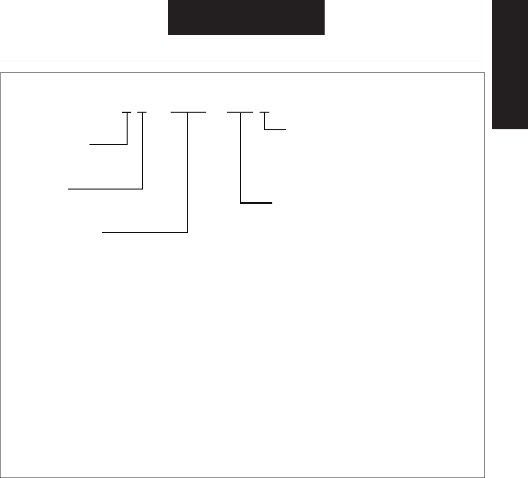
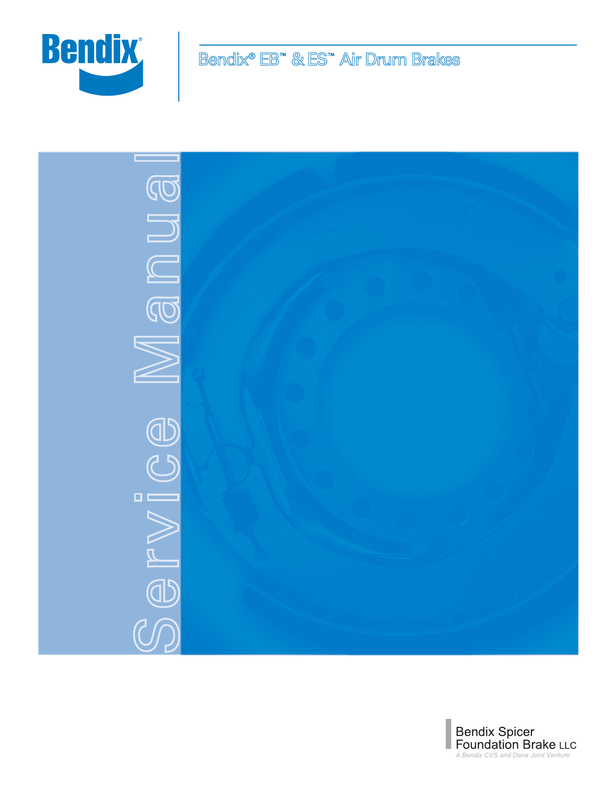
Figure 2. Bendix Brake Model Identifi cation
General Information
Model Coverage
E S - 1 5 0 - 0 8 D
Service
Configuration
B - Standard Service
S - Extended Service
Drum Diameter
Example: L = Fabricated Shoe
Fabricated Spider
Single Anchor Pin (SAP)
Shoe Size
Example: (219mm)
8 = 8.63"
150 – 15" (381 mm)
165 – 16.5" (419 mm)
180 – 18" (457 mm)
Shoe Size
04 - 4" – (102 mm)
05 - 5" – (127 mm)
06 - 6" – (152 mm)
07 - 7" – (178 mm)
07 - 7.5” – (191 mm)
08 - 8.63" – (219 mm)
10 - 10" – (254 mm)
Configurations
A - Fab Shoe Weld On Spider Self Contained Cam Bracket SAP
B - Fab Shoe Weld On Spider Self Contained Cam Bracket DAP
D - Fabricated Shoe/Cast Spider SAP
F - Fabricated Shoe
Weld On Spider SAP (Non Self Contained)
H - Cast Shoe/Heavy Cast Spider DAP
L - Fabricated Shoe/Fabricated Spider SAP
M - Fabricated Shoe/Cast Spider (DAP Closed A/P)
P - Fabricated Shoe/Weld On Spider (DAP Closed A/P)
R - Cast Shoe/Heavy Cast Spider SAP
S - Reinforced Fabricated Shoe/Heavy Cast Spider (SAP)
T - Fabricated Shoe/Weld On Spider DAP (Non Self Contained)
SAP - Single Anchor Pin
DAP - Double Anchor Pin
Manufacturer
Bendix Spicer
Foundation Brake
122 – 12.25" (311 mm)
Camshaft
Shoe Assembly
Shoe Assembly
Shoe Retainer
Spring
Color - Blue
Cam Roller
Cam Roller
Shoe Return
Spring
Color - Blue
Dustshield
Shoe*
Hold-Down
Spring
Bolt*
Nut
Washer
Spider
Assembly*
Grease
Seal
Camshaft
Bushing
Bracket
Assembly
Camshaft
Bushing
Bolt
Grease
Seal
Brake Adjuster
Inner Washer
Camshaft
Shim
Washer
Camshaft
Retainer
Snap Ring
Brake
Adjuster
Stabilizer Nut
Dustshield Screw
*Shoe Hold-Down Spring and Guide Variation
Camshaft
Shoe Assembly
Shoe Assembly
Roller
Shoe Return
Spring
Color - Grey
Grease
Fitting
Retainer
Roller
Grease
Seal
Bracket
Assembly
Camshaft
Bushing
Cam Head
Washer
Grease
Seal
Brake Adjuster
Inner Washer
Camshaft
Shim
Washer
Camshaft
Retainer
Snap Ring
Retainer
Shoe
Return Spring
Color - Red
Cast
Spider
Camshaft
Bushing
Brake Adjuster
Lock Washer Nut
Inspection
Hole Plug
Dustshield
Bracket
Stud
Parts Nomenclature
---
-
--
-
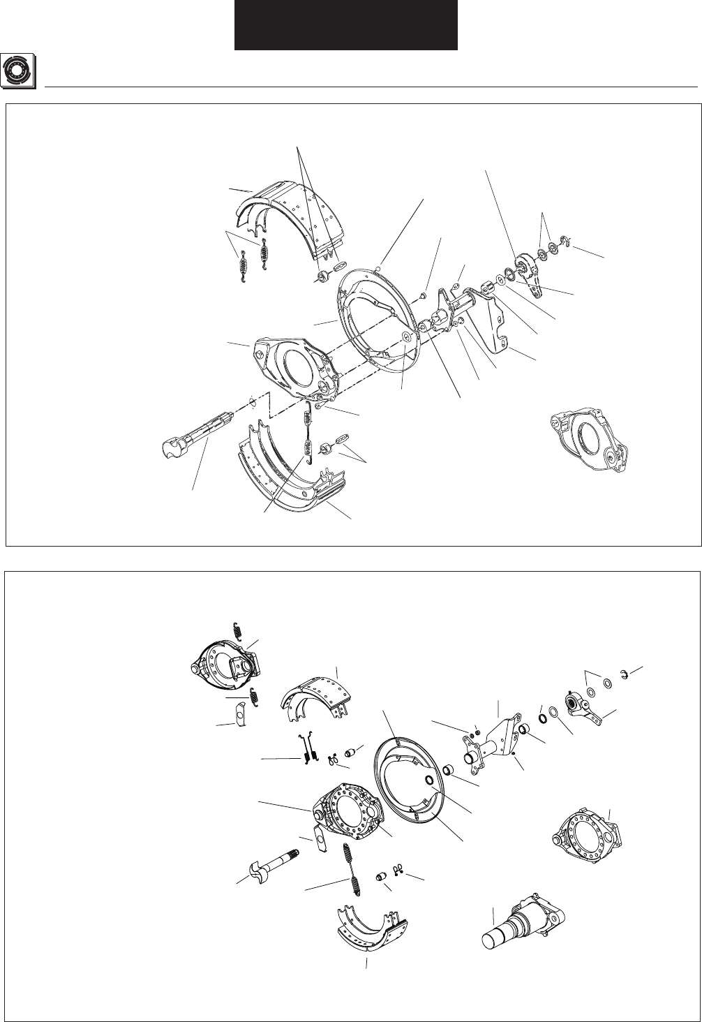
Figure 3. Brake Part Nomenclature, General
Barrel Nut
Shoe Hold-Down Spring
Shoe
Spacer
Standard Nut Shoe Guide and Shoe
Hold-Down Spring
Old Style
Shoe Hold-Down Spring and Guide Variation
New Style
Shoe Spacer Not Required
(Must be Removed for New Sty
le Hold-Down)
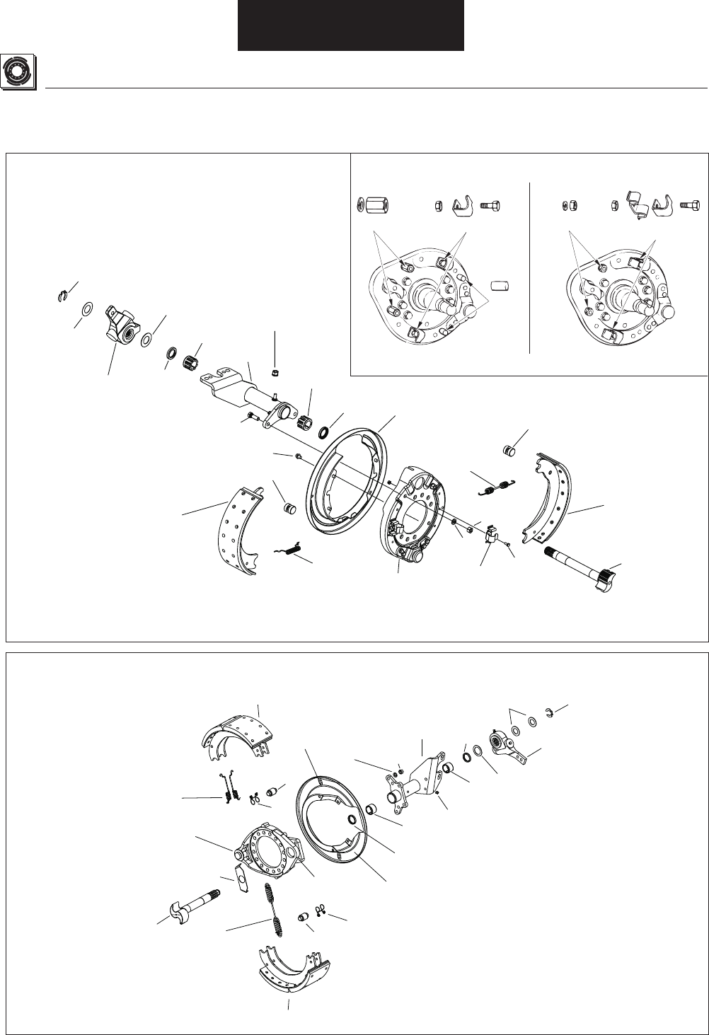
General Information
Camshaft
Shoe Assembly
Shoe Assembly
Roller
Shoe Return
Spring
Color - White
Grease Fitting
Retainer
Roller
Grease
Seal
Bracket
Assembly
Camshaft
Bushing
Cam Head Washer
Grease
Seal
Brake Adjuster
Inner Washer
Camshaft
Shim
Washer
Camshaft
Retainer
Snap R
ing
Spider
(Stamped Steel)
Retainer
Shoe
Retainer Springs
Color - Orange
Brake Adjuster
Camshaft
Bushing
Forged Spider
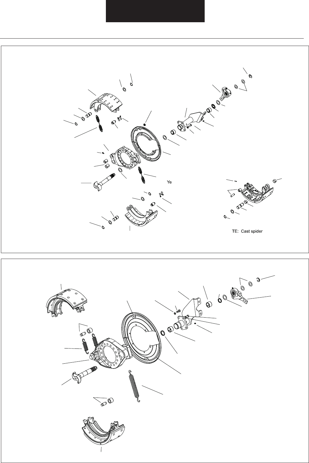
Figure 4. Brake Model Part Nomenclature
-
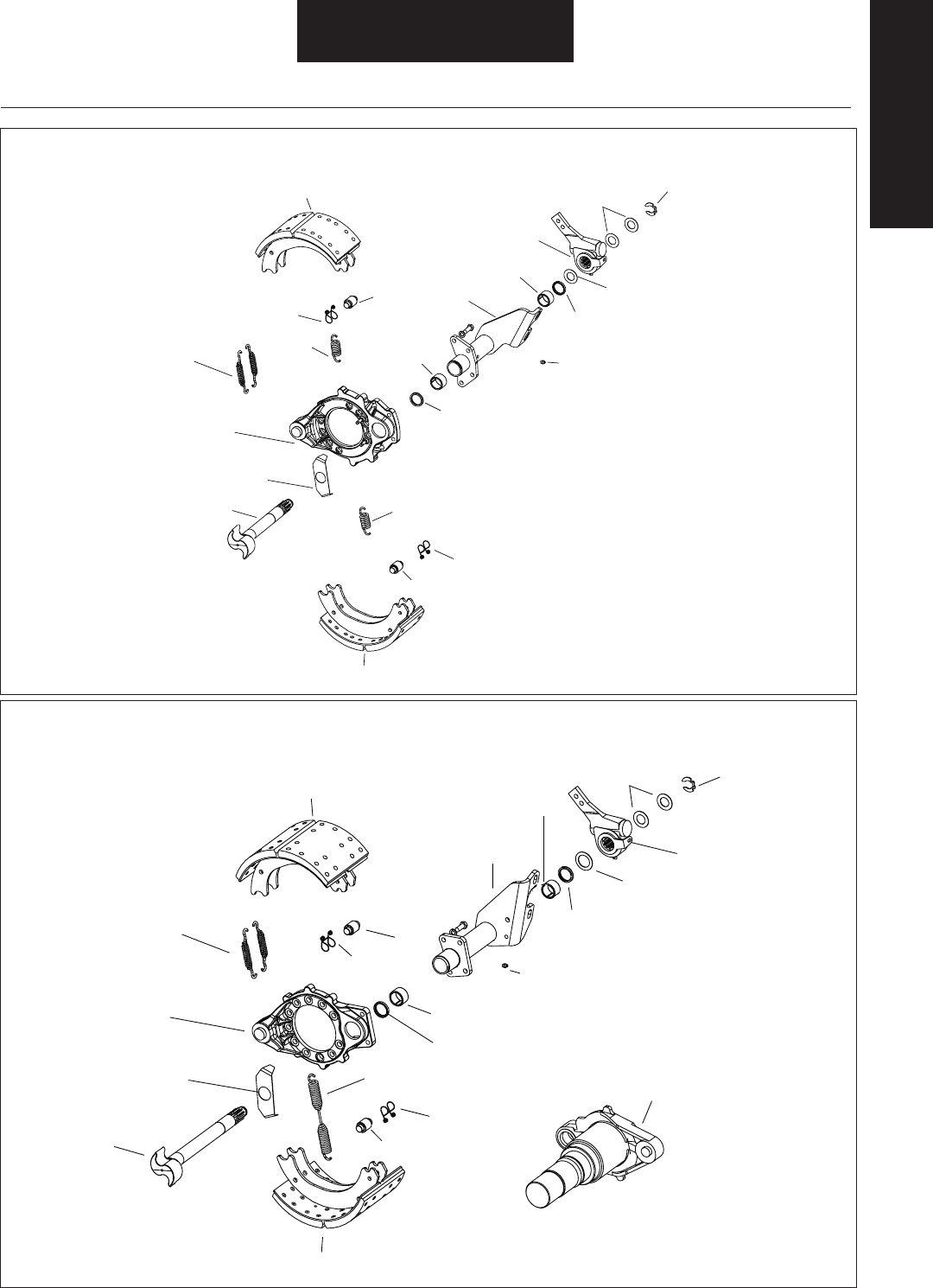
General Information
Parts Nomenclature
Camshaft
Shoe Assembly
Shoe Assembly
Shoe Return
Spring
Color - Red
Roller
Shoe Return
Spring
Grease Fitting
Retainer
Roller
Grease
Seal
Bracket
Assembly
Camshaft
Bushing
Cam Head Washer
Grease
Seal
Brake Adjuster
Inner Washer
Camshaft
Shim
Washer
Camshaft
Retainer
Snap Ring
Spider
(Stamped Steel)
Retainer
Shoe
Retainer Springs
Color - Orange
Brake
Adjuster
Camshaft
Bushing
Parts Nomenclature
-
-
Cam Roller
and pin
Shoe Return Spring
Bracket Stud
Camshaft
Spider
(Stamped Steel)
Dustshield
Shoe Retainer
Springs
Color - Orange
Shoe Assembly
Shoe Assembly
Cast Spider
Cast spiders are tapped
and require 4 bolts and lock-
washers to attach air
chamber bracket assembly.
Camshaft
Bushing
Lockwasher
Nut
Bracket Assembly
Camshaft Bushing
Brake Adjuster
Inner Washer
Brake Adjuster
Camshaft
Shim Washers
Camshaft
Retainer
Snap Ring
Grease Seal
Grease
Fitting
Dustshield
Screw
Inspection
Hole Plug
Grease Seal
Cam Roller and Pin for
EB-165 and EB-180 Brakes
Two-Piece Roller and Pin
Figure 4. Brake Model Part Nomenclature, Continued
General Information
Camshaft
Shoe Assembly
Shoe Assembly
Roller
Shoe Return
Spring
Color - Grey
Grease
Fitting
Retainer
Roller
Grease
Seal
Bracket
Assembly
Camshaft
Bushing
Cam Head
Washer
Grease
Seal
Brake Adjuster
Inner Washer
Camshaft
Shim
Washer
Camshaft
Retainer
Snap Ring
Spider
(Stamped Steel)
Retainer
Shoe
Return Spring
Color - Red
Cast Spider
With Horse
Collar
Forged
Spider
Cast
Spider
Camshaft
Bushing
Brake Adjuster
Lock Washer Nut
Inspection
Hole Plug
Dustshield
Bracket
Stud
Shoe
Retainer Springs
Color - Orange
Cam Head Washer
Camshaft
Shoe Assembly
Shoe Assembly
Camshaft Roller
and pin
Shoe Return
Spring
Color - Green
Camshaft Roller
and Pin
Grease
Seal
Bracket
Assembly
Camshaft
Bushing
Grease
Seal
Brake Adjuster
Inner Washer
Camshaft
Shim
Washer
Camshaft
Retainer
Snap Ring
Spider
(Stamped Steel)
Shoe
Retainer Springs
Color - Orange
Camshaft
Bushing
Brake Adjuster
Inspection
Hole Plug
Dustshield
Grease
Fitting
Lock Washer
Bolt
Bracket Bolt
Lock Washer
Cast Spider H version
Camshaft
Shoe Return
Spring
Color - llow
Grease Fitting
Retainer
Roller
Grease Seal
Bracket
Assembly
Camshaft Bushing
Grease Seal
Brake Adjuster Inner Washer
Camshaft
Shim Washer
Camshaft
Retainer
Snap Ring
Cast
Spider Camshaft Bushing
Brake Adjuster
Bracket Lock Washer
Fabricated Shoe Assembly
Fabricated Shoe Assembly
Dustshield
NO s are tapped
and require four bolts and lockwashers
to attach air chamber bracket assembly.
Inspection
Hole Plug
Cast
Shoe Return Spring
Color - Orange
Bolt
Washer
Snap Ring
Snap Ring
Washer
Anchor Pin
Roller
Retainer
Nut
Anchor Pin
Bushings
Washer
Washer
Snap Ring
Snap Ring
Washer
Anchor Pin
Bushing
Roller Dowel Pin
Bushing
Anchor Pin
Washer
Snap Ring
Camshaft Roller
and Pin
General Information
Model ES-165 and EB-165 Interchangeability
-
-
-
----
-
“On-Road” Repair:--
---
-
----
---
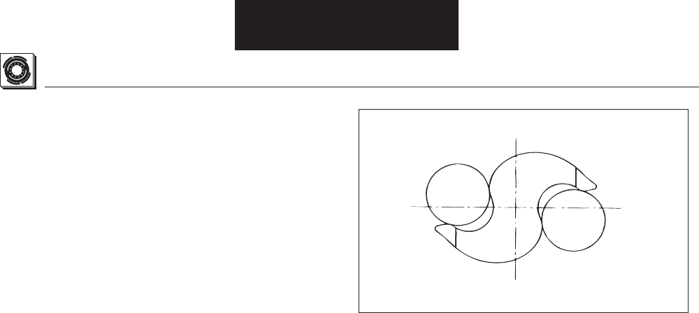
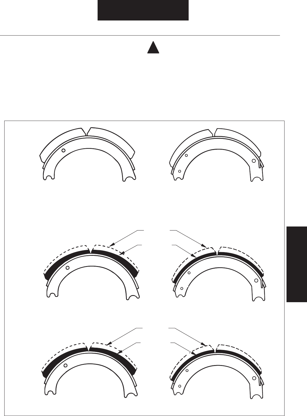
EB™ Roller and ES™ Cam Interchangeability
---
----
---
NOTE:----
Figure 5. EB™ Roller and ES™ Cam Contact Pattern
Parts Nomenclature
General Information
EB Roller ES Cam
Normal
Contact
Pattern
-
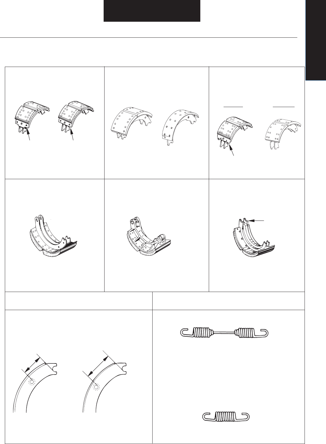
Figure 6. Parts Identifi cation
ES-165-D,L,F
-
ES-150-D,F ES/EB 150-4L
General Information
Parts Nomenclature
Shoe
with Tab
All EB-165 Models
Shoe
without Tab
Shoe with Spring
Attaching Lugs
Double Anchor Pin
with Cam Roller
and Anchor Pin
Bushings
ES-165-7H
Single Anchor Pin
EB-180-7R
“High-Mount”
Shoe
“Low-Mount”
Shoe
3 1/2"
(88.9 mm)
4"
(101.6 mm)
All EB-165 Models
-
Double Anchor Pin
ES-165-7M
Color-Coded by Application
Blue
White
Red
Black
Grey
Yellow
Orange
Green
Red
. . . . . ES-150-4L/EB-150-4L
. . . . . ES-150-8D, 8F
. . . . . Use with "High-Mount"
Shoes (All EB-165)
. . . . . Use with "Low-Mount"
Shoes (All EB-165)
. . . . . ES-165-5D, 5L, 6D, 6L,
7D, 7L, 7F, 8D, 8L, 8F
. . . . . ES-165-7M
. . . . . ES-165-7H
. . . . . EB-180-7R
. . . . . ES150-6D
ES165-5D, 5L, 6D, 6L, 7D, 7L
Spider Part No.
Location
Air Chamber
Bracket Flange
Shape for
Cast Spider
Cast Spider
Double Anchor Pin
Air Chamber
Bracket Flange
Shape for
Cast Spider
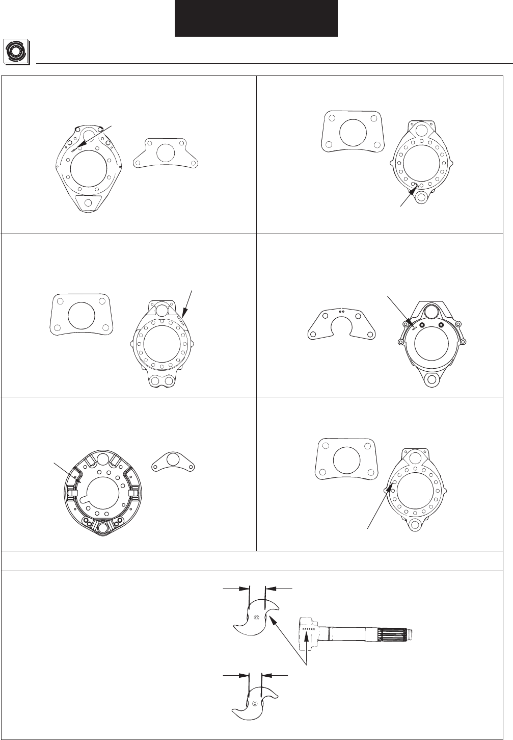
Spider Part No.
Location
Cast Spider
Single Anchor Pin
Spider Part No.
Location
Air Chamber
Bracket Flange
Shape for
Stamped Spider
Lightweight Stamped Spider
Single Anchor Pin
Air Chamber
Bracket Flange
Shape for
Cast Spider
Spider Part No.
Location
Figure 6. Parts Identifi cation, Continued
-
Stamped Spider ES/EB-150-4L
General Information
Camshaft Part No.
Location
Cam Head for EB-165 and
EB-180 Brakes
Cam Head for ES-165, ES-150-D
and ES-150-F Brakes
1-3/8"
1-1/8"
-
-
-
XXXXXX
XXXXX
-
-
-
Brake Adjustment - Manual Brake Adjuster
NOTE:
WARNING:----
-
-
-
1.--
2.--
---
-
--
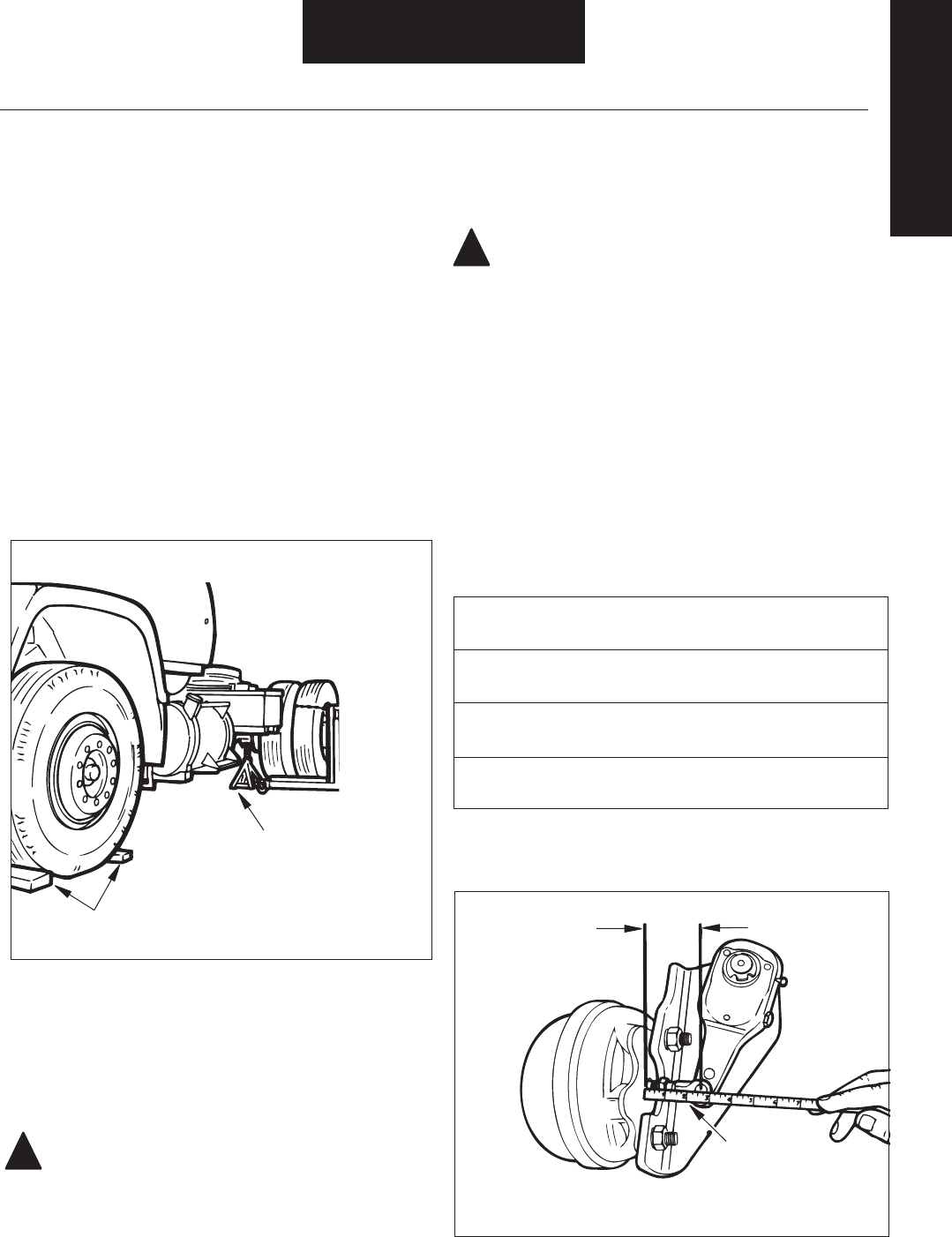
Figure 8. Measurement, At Rest
!
Distance: Clevis Pin Hole
Centerline to Air Chamber Face
--
--
--
Table 2. Distance Range
--
---
---
-
---
Brake Maintenance Preliminary Steps
-
----
Figure 7. Vehicle Maintenance Support
1.---
2.--
WARNING: -
3.---
!
Maintenance and Adjustment
Periodic Service
Parts Identifi cation
Block Wheels
Support On
Jack Stands
of Adequate
Capacity
Measure This
Distance with
Chamber “At Rest”,
Dimension “A”
A

B
Measure This
Distance
at 80 psi,
Dimension “B”
3.---
--
5. -
--
-
-
6. --
--
-
7.-
---
8. Brake Operation Check,
--
Brake Adjustment - Automatic Slack Adjuster
NOTE: A properly working Automatic Slack Adjuster does not require
manual adjustment while in service. The manual adjuster hex is
intended for use during adjuster installation and brake overhaul.
WARNING: Automatic slack adjusters must never be repeatedly
adjusted to correct excessive in service pushrod stroke, because this
condition indicates that a problem exists with the automatic adjuster,
with the installation of the adjuster or with related foundation brake
components which manual adjustment will not correct.
-
-
-
--
NOTE:
--
--
--
-
-
4.-
----
--
-
Brake Operation Check
Figure 9. Measurement, 80 psi Applied
Figure 10. Measurement, Brake Applied
80 - 90 PSI
Air Chamber Maximum Desired
Size Applied Free
Stroke Stroke
Maintenance and Adjustment
Table 3. Stroke Values
Periodic Service
B
Measure with
Brake “Applied”
Using Lever,
Dimension “B”
Lever

Periodic Service
Maintenance and Adjustment
Brake Operation Check
NOTE:
1.-----
-
2.---
---
---
3.
!
4.---
---
--
CAUTION:--
Lubrication
------
---
-----
-----
---
Do Not Lubricate The Following:
--
Note:---
---
CAUTION:-----
Important:-------
Component Lubrication Interval Type of Lubricant
-
- -
-
Table 4. Lubrication Intervals
Note: --
----
---
--
Brake Adjuster Lubrication:
!

Service Intervals
Brake Reline
---
Camshaft Radial Play
----
-
Camshaft Inspection.
Camshaft Axial Play
---
-
-- Brake Adjuster Installation
Brake Overhaul
----
---
-
Lubrication
Periodic Service / Lubrication --
-
Periodic Inspections
--
----
-
Brake Overhaul
Visual Inspection
--
-
-In no case
should the visual inspection interval exceed 3 months of service.
Lining Inspection
---
-In no case
should the lining thickness/condition inspection interval exceed 3
months of service.
Brake Adjustment
Brake Adjustment should be checked (and adjusted if necessary)
WEEKLY or any time applied stroke exceeds the maximums shown
in Periodic Maintenance: Brake Adjustment - Manual Brake
Adjuster.
Brake Operation Check
--
--Brake Operation Check
In no case should the operation check interval exceed 3
months of service.
Periodic Service

3. --
----
-
--
WARNING:-
---
4. --
5. ------
-
6.---
-
CAUTION:--
--
!
Figure 11. Brake Adjuster Adjustment
--
--
-
-
-
--
-----
--
WARNING: The long-term effects of non-asbestos fi bers
have not been determined. Therefore, precautions should
be used when handling these materials.
See General Information / Lining Material Warning
!
Removal / Disassembly
Check, Lubrication,
Inspection, Service
Drum Removal
1.“Brake Maintenance Preliminary Steps”
2.---
-
-----
---
!
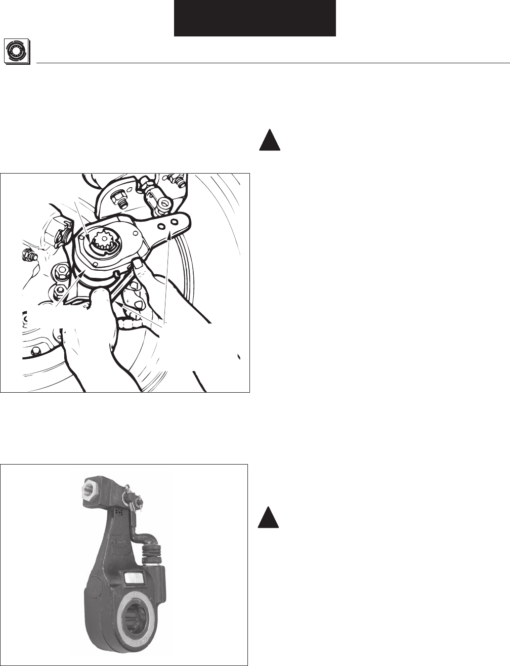
Depress Locking
Sleeve and Turn
Adjuster Nut to
“Back-Off”
Adjustment

Shoe Removal
---
-
--
Shoe Removal
Table 5. Shoe Removal Procedure Index
Removal / Disassembly
Brake Model Page Number Brake Model Page Number
EB-150-4L
22 EB-180-7R 20
EB-165-5D 20 ES-150-4L 22
EB-165-5L 20 ES-150-6D 20
EB-165-6D 20 ES-150-8D 20
EB-165-6L 20 ES-150-8F 20
EB-165-7D 20 ES-165-5D 20
EB-165-7L 20 ES-165-5D 20
EB-165-7F 20 ES-165-5L 20
EB-165-8D 20 ES-165-6D 20
EB-165-8F 20 ES-165-6L 20
EB-165-8L 20 ES-165-7F 20
ES-165-7H 25
ES-165-7L 20
ES-165-7M 23
NOTE: The following procedures are divided into sections,
identifi ed by brake model numbers.
Shoe Removal
EB models (except EB-150-4L)/ES-165-5D,L /
ES-165-6D,L / ES-165-7D, F, L / ES-150-8D, F /
ES-150-4D/ES-150-6D/ES-165-8D,F,L
1.Removal/Disassembly: Drum Removal.
2. ES-165-5,6,7,8,D,L,F, ES-150-4D, ES-150-8D, F & 6D ONLY:
-----
----
NOTE:---
WARNING:-
-
--
See General Information / Lining Material Warning
3.---
4. --
NOTE:
----
5.---
NOTE:--
--
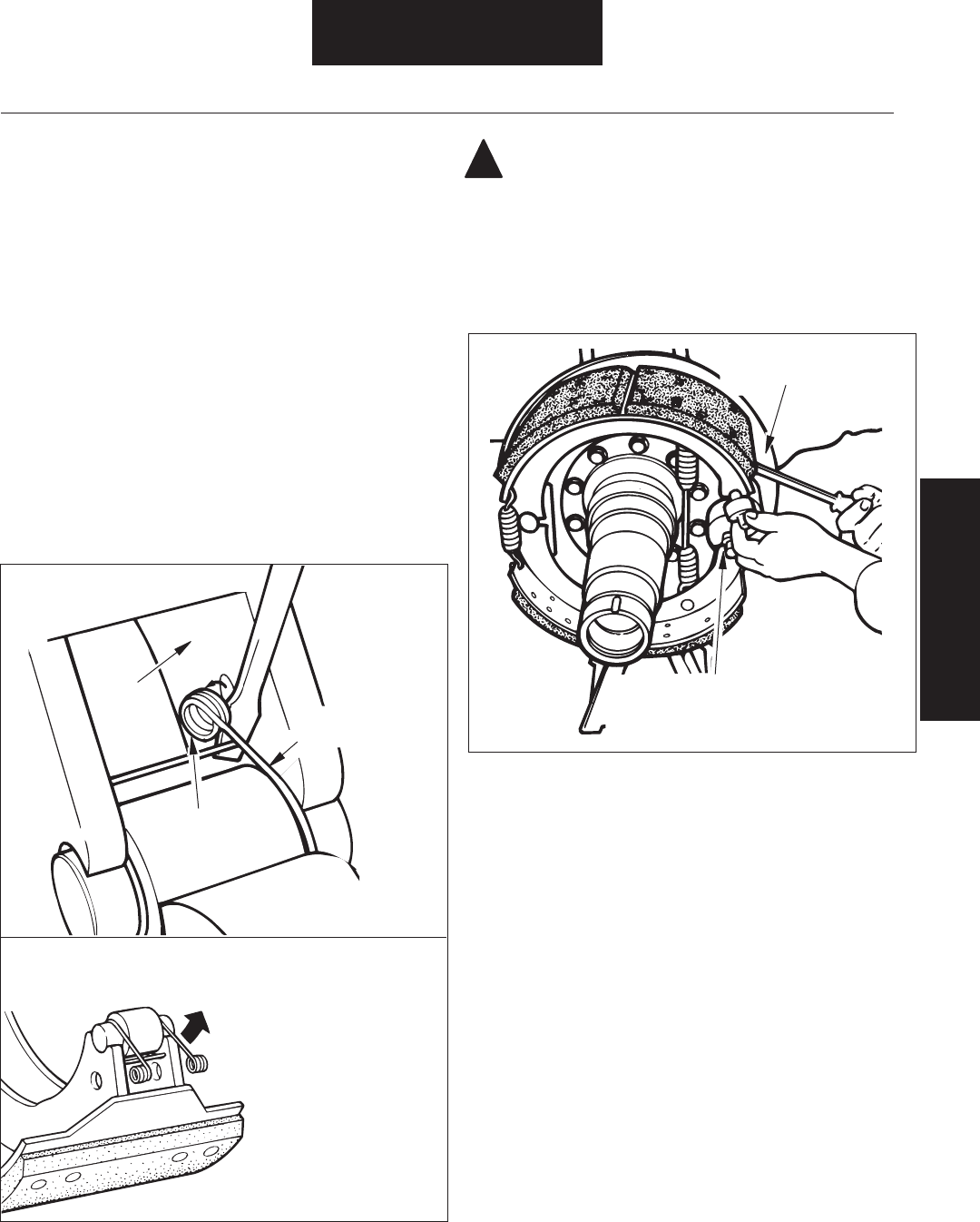
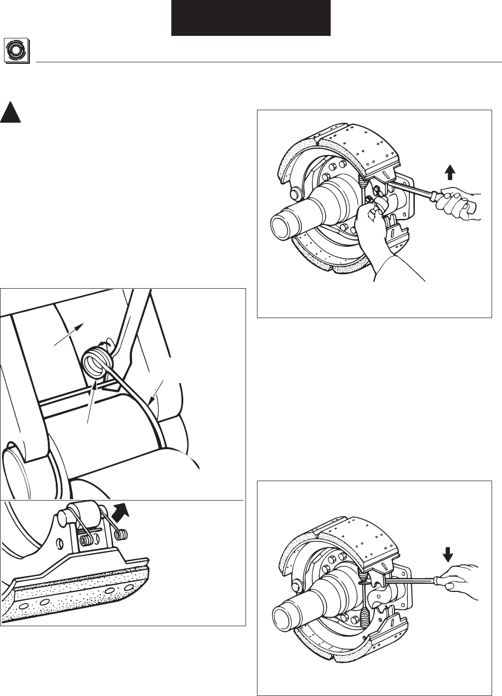
Figure 13. Upper Cam Roller and Pin Removal
Figure 12. Roller Retainer Removal
!
Removal / Disassembly
Drum/Shoe Removal
Pivot Retainer to
Swing Loops Clear
of Shoe Web
ES-165-7D, L, F Only
Remove Roller and Pin, Then
Repeat for Lower Shoe.
For ES Brakes, See Note Below
Lift Upper Shoe
to Stretch Spring
ES-165-7D, L, F Only
Shoe
Web Roller
Retainer
Disengage
Retainer Coiled
Loops From
Shoe Webs
-
---
---
-
---
-
--
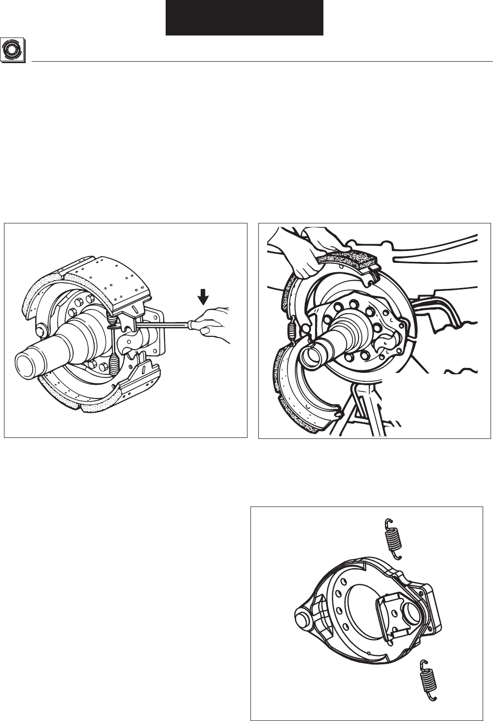
Figure 15B. Cast Spider With Horse Collar
Shoe Removal
6.
NOTE:---
-
---
7.-
8.---
--
Figure 14. ES-165-7D, L, F Shoe Removal Figure 15. Shoe Removal
Removal / Disassembly
ES-165-5D,L / ES-165-6D,L
ES-165-7D,L,F Only:
Stretch Using Suitable
Tool Positioned
As Shown
Rotate Both Shoes
Around Anchor
Pin and Lift Off
Brake Shoes

ES-150-4L and EB-150-4L Brakes
1. ---
2. ---
3. --
4. ---
5.
Figure 16. Shoe Return Spring Removal
6. --
-
7.
8. Clean - Removal/
Disassembly-
Figure 17. Lower Shoe Removal
WARNING:-
-
--
See General Information / Lining Material Warning
!
Removal / Disassembly
Shoe Removal
Shoe Return
Spring
Stretch Spring to
Unhook from
Shoe Web
Rotate Down
Unhook
Retaining
Spring
4.---
--
Figure 19. Roller and Retainer Removal
Figure 20. Return Spring Removal
Figure 18. Retainer Loop Removal
5. ---
-
6. ---
-
---
Shoe Removal
ES-165-7M Heavy-Duty Brake
WARNING:-
-
--
See General Information / Lining Material Warning
1.-Removal /
Disassembly - Drum Removal.
2. ---
3.-----
----
!
Removal / Disassembly
Shoe
Web Roller
Retainer
Disengage
Retainer Coiled
Loops From
Shoe Webs
Pivot Retainer to
Swing Loops Clear
of Shoe Web
Lift Upper Shoe
to Stretch Spring
Remove Roller and Retainer, Then
Repeat for Lower Shoe
Stretch Spring
Using Suitable
Tool Positioned
As Shown
ES-165-7M Heavy-Duty Brake, Continued
7.
9.-
--
8.----
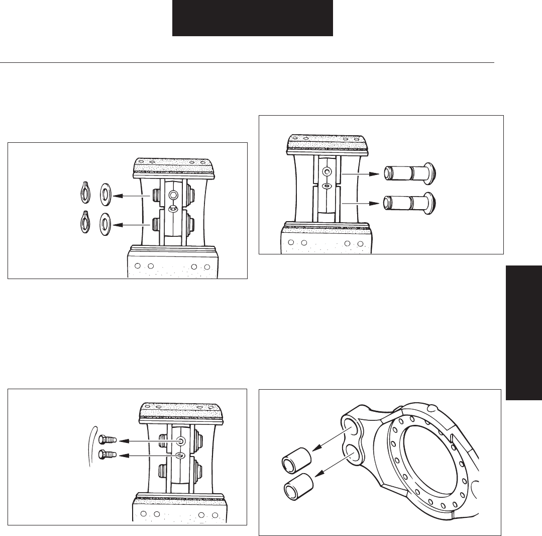
Figure 21. Retaining Ring and Washer Removal
Figure 22. Cap Screw Removal
Figure 23. Anchor Pin Removal
NOTE:
-
---
10.-
Figure 24. Anchor Pin Bushing Removal
11.--Removal/
Disassembly-
Removal / Disassembly
Shoe Removal
Remove
Retaining
Rings and
Was
hers
Cut Lock Wire
and Remove
Cap Screws
Drive Out
Anchor Pins
Drive Out Bushings
with a Suitable Driver
4. ----
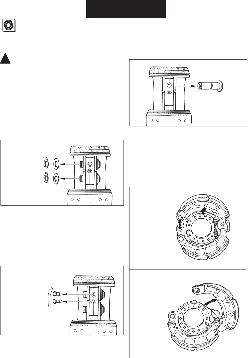
Figure 26. Cap Screw Removal
Figure 25. Retaining Ring and Washer Removal
5. --
6.--
Figure 27. Anchor Pin Removal
Figure 28. Shoe Removal
Shoe Removal
ES-165-7H Severe Duty Brake
WARNING:-
-
--
See General Information / Lining Material Warning
1.-Removal
Disassembly - Drum Removal.
2.---
3.
!
Removal / Disassembly
Remove
Retaining
Rings and
Was
hers
Cut Lock Wire
and Remove
Cap Screws
Drive Out
Anchor Pin
Rotate Upper
Shoe Around
Cam End
Disengage Shoe
End From Cam . . .
Then Unhook
Return Spring
and Remove Shoe
7. --
NOTE:
-
---
8.-
-
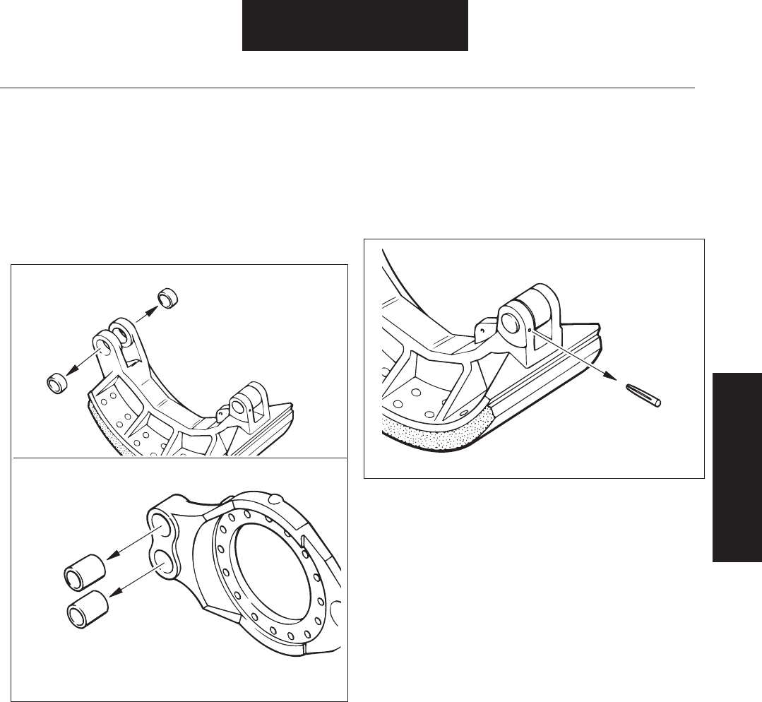
Figure 29. Anchor Pin Bushing Removal
9.-----
-----
---
----
--
Figure 30. Groove Pin Removal
10.--Removal/
Disassembly-
Removal / Disassembly
Shoe Removal
Drive Out
Bushings with
Suitable Driver
Drive Out Bushings
with a Suitable Driver
Drive Out
Groove Pin
Remove
Snap Ring
Use Puller
to Remove
Rotate Adjuster
Until Slack
Adjuster is
Clear of Clevis
1.--
2.----
--
NOTE:---
3.
Figure 31. Brake Adjuster Removal
Brake Adjuster Removal
!
4.
--
---
CAUTION:
-
-
Camshaft Removal
1.---
-Removal / Disassembly
2.--
Air Chamber Bracket Removal
1. --
--Removal / Disassembly
2.-
3.-
--
NOTE:
-
NOTE:-
-
Removal / Disassembly
Bendix® ASA-5® Automatic Slack Adjuster
WARNING: -
!
-
--
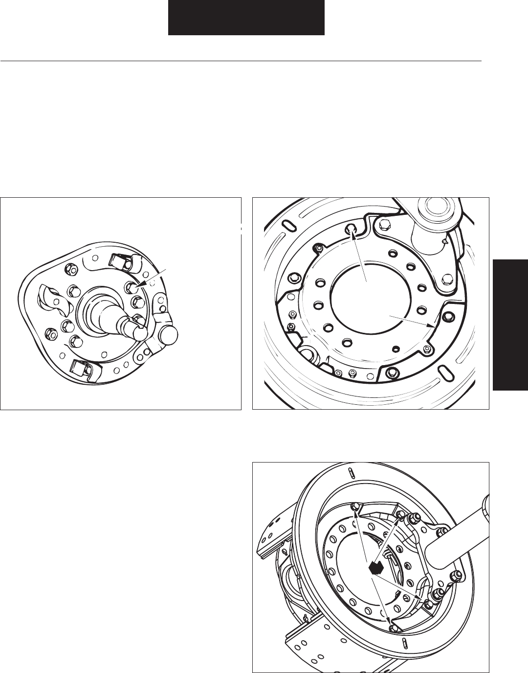
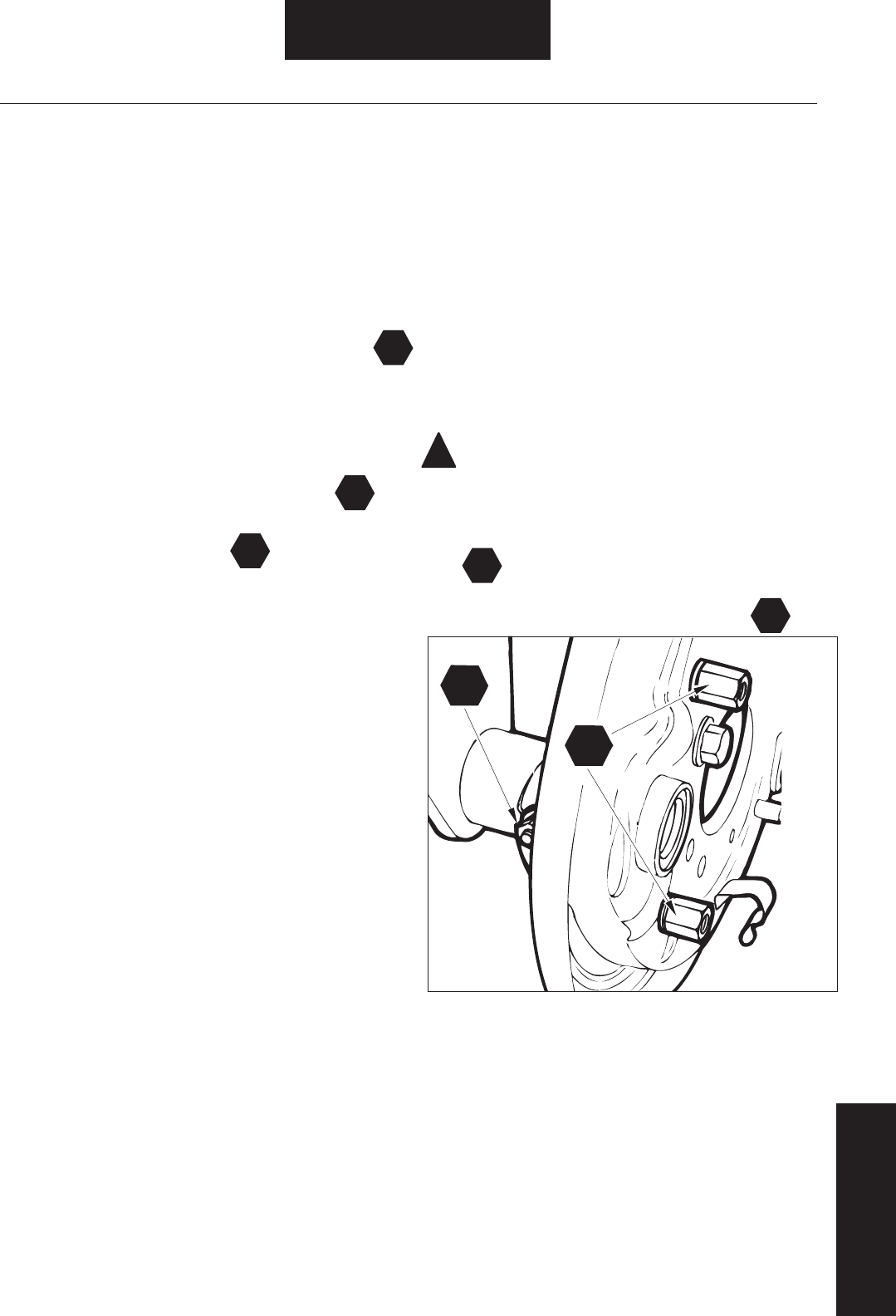
Figure 32. Spider Mounting Hardware Removal Figure 33. Dustshield Mounting Hardware Removal
For All 165-5,6,7,8L Models
Dustshield Removal
NOTE:-
1.-----
-
-
2.-
Removal / Disassembly
Shoe/Brake Adjuster/
Camshaft/Bracket Removal
Spider Removal
1. ----
Removal / Disassembly
2.--
3.
Remove All
Four Screws
Dustshield
--
-
T

--
----
---
--
CAUTION:-
--
• -
--
---
WARNING:-
-
--
--
--
See General Information / Lining Material Warning
!
!
Removal / Disassembly
Cleaning Brake Parts
Drum Inspection
--
-
---
-
-
-
• -----
----
NOTE:-
-
1. -
--
2.-
CAUTION: -
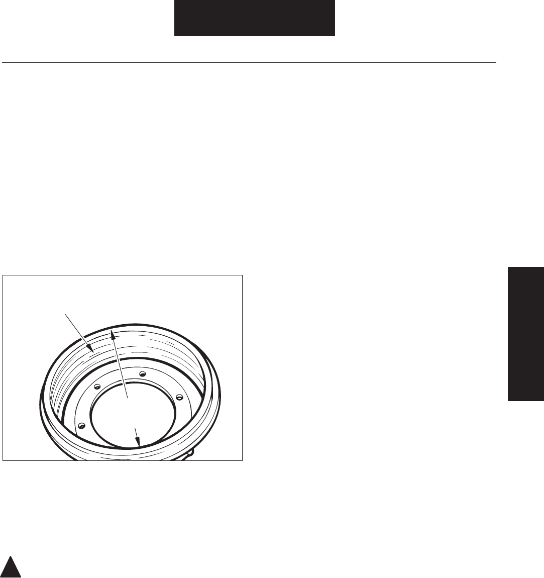
Figure 34. Drum Inspection
!
Drum Inspection
Inspection
Spider / Dustshield
and Cleaning
Check for Cracks,
Heat Checks, Glazing
and Grooving
Check Diameter
and
Out-of-Round
Inspection
Inspection
4. --
---
-
NOTE: --
-
----
Important:
----
-
-
1.
--
--
-
-
-
2.
3.--
---
-----
--
-
--
-
4.
--
-
Shoe and Lining Inspection
1. --
---
---
2.--
----
Brake Roller Anchor
Model End Pin End
----
3.ES-165-7H severe duty brake only:
Inspection-Spider
Inspection-
NOTE: --
--------
-----
------
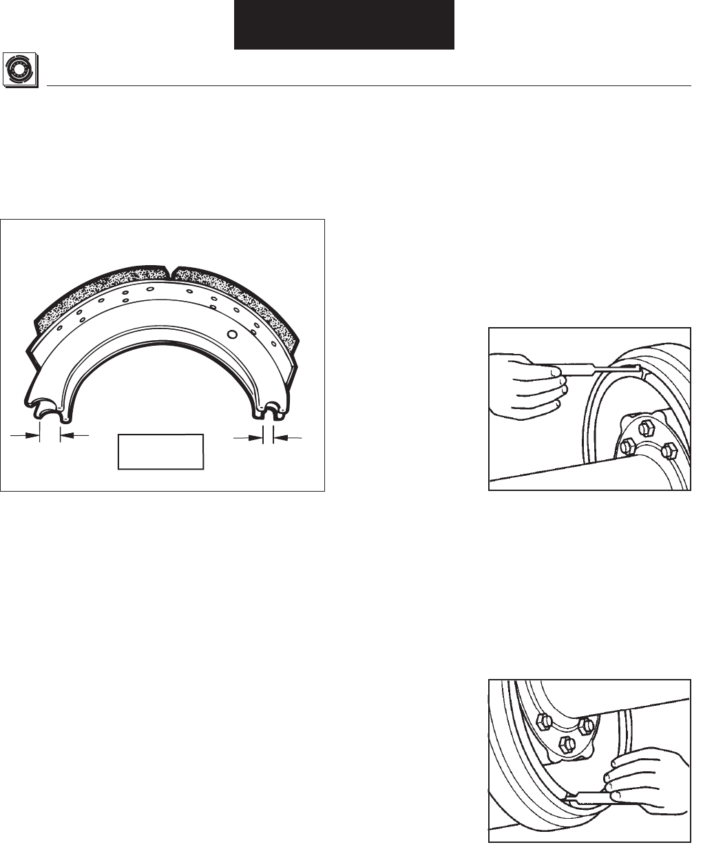
Figure 36. Shoe and Lining Inspection
5.
---
Anchor
Pin End Roller End
See Chart for
Specifications
Check Table and Web for Cracks and Bends
Check Both Ends
for Wear and
Elongation
Wearable
Lining
Remaining
Lining
Worn All EB-165
(Standard Production)
Worn 150-4D, 150-80, F & 6D
ES-165-7D, L & F
(Extended Service)
Minimum
Thickness
At Any Point
1/4" (6.4mm)
Minimum
Thickness
At Any Point
1/4" (6.4mm)
WARNING: -
-
--
See General Information / Lining Material Warning
Figure 37. Brake and Lining Blocks
--
---
----
--
-------
-
!
Inspection
Drum / Shoe and
Lining Inspection
-
--
--
Shoe and Lining Inspection (cont’d)
New - All EB
(Standard Production)
New- ES-150-8D, F & 6D
165-7D,L & F
(Extended Service)
Minimum
Thickness
At Any Point
3/16" (4.5 mm)
Worn EB-150-4L
(Standard Production)
Minimum
Thickness
At Any Point
3/16" (4.5 mm)
Worn ES-150-4L
(Extended Service)
Wearable
Lining
Remaining
Lining
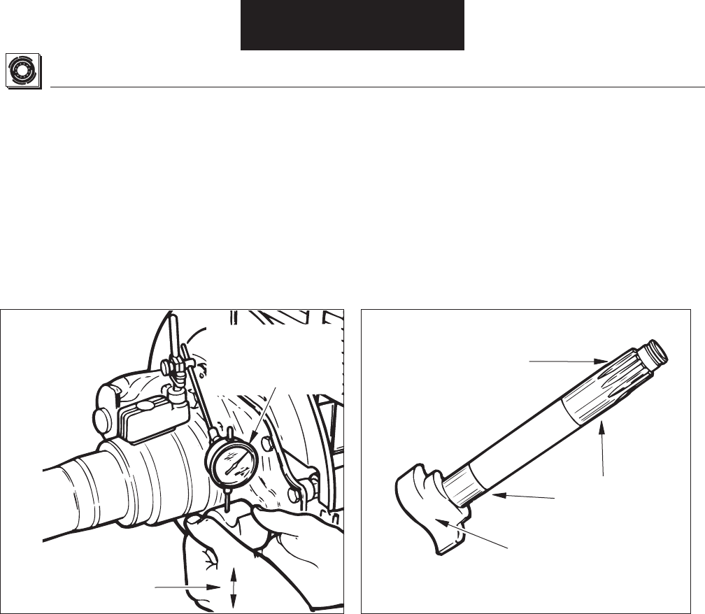
Figure 38. Camshaft Radial Play Inspection Figure 39. Camshaft Inspection
Inspection
Inspection
Camshaft Radial Play Inspection
---
-
1.---
--
2.-
3.
4.-
Repair/Replacement - Camshaft Bushing and Grease Seal
Replacement.
NOTE:---
-See Repair/Replacement -
Camshaft Bushing and Grease Seal Replacement.
5.-----
Camshaft Inspection
1.-
--
2.-
---
-
3.--
--
Camshaft Bushing and Seal Inspection
NOTE:--
-
1.
-
Repair/Replacement - Camshaft Bushing and Grease Seal
Replacement.
2.----
Repair/Replacement - Camshaft Bushing and
Grease Seal Replacement.
Move Camshaft,
Note Maximum
Deflection
If More Than .035"
(.91mm), Replace
Bushings and
Recheck
Check for Cracks, Wear
or Deformed Splines
Check for Wear,
Roughness and
Corrosion
Check for Wear,
Cracks and
Flat Spots
SPECIAL NOTE:
!
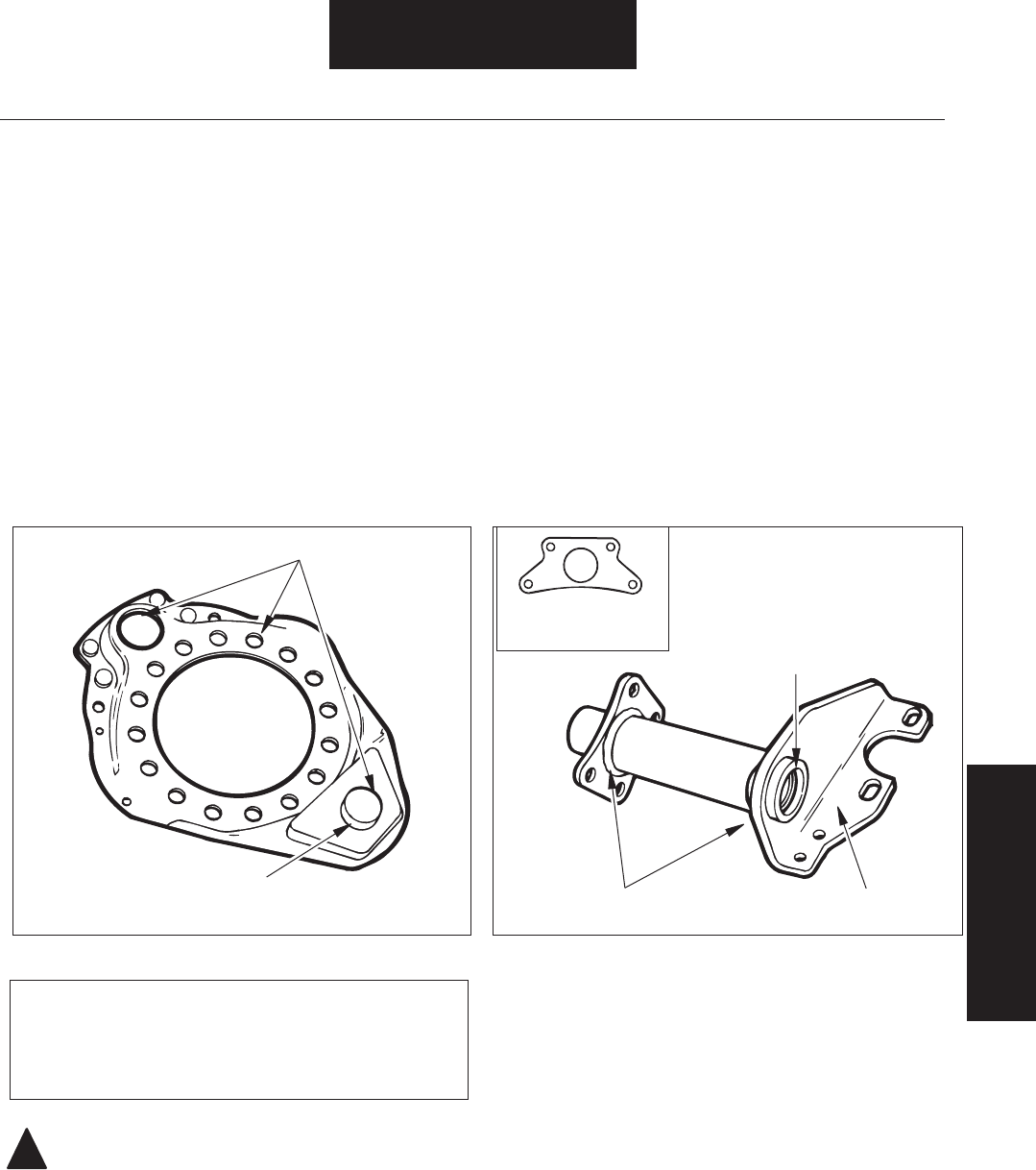
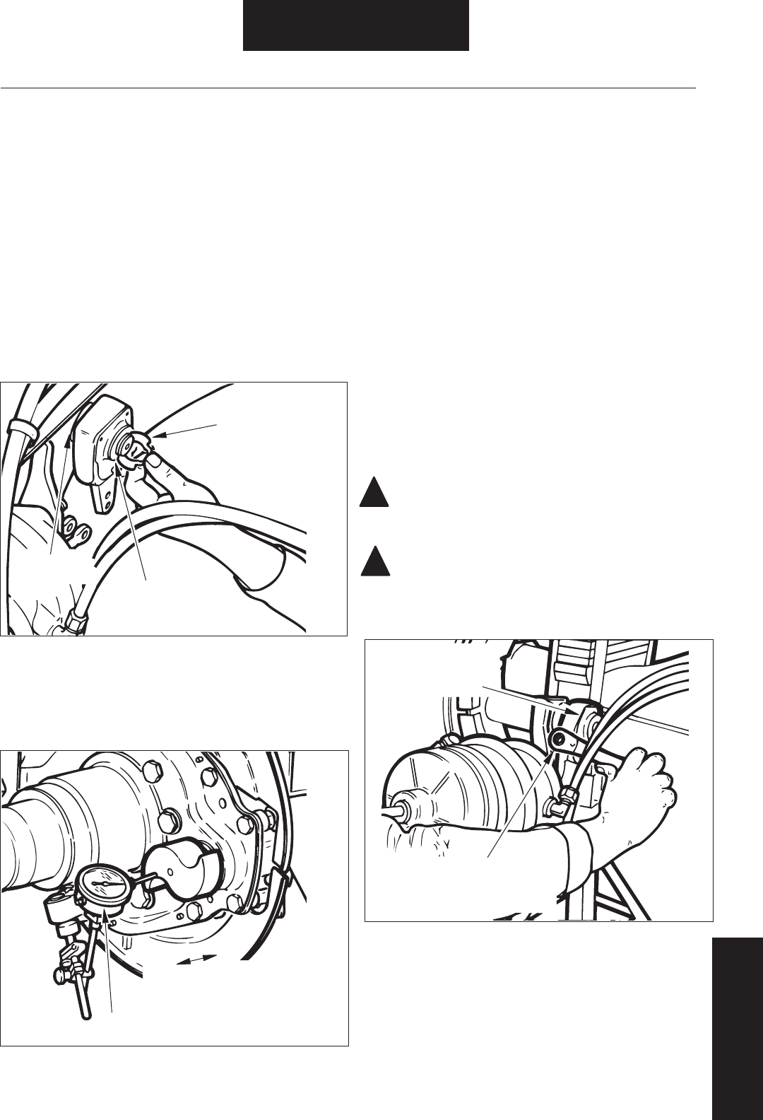
Figure 40. Spider Inspection Figure 41. Air Chamber Bracket Inspection
-
Inspection
Shoe and Lining
& Camshaft Inspection
Spider Inspection
Single Anchor Pin
1.----
-
2. -
----
NOTE:---
3.
---
CAUTION: -
--
Spider Inspection (Double Anchor Pin)
1.----
-
2.
--
--
NOTE: --
Air Chamber Bracket Inspection
1. -
-
2.--
-
Check for Cracks
Check for Grooved or
Loose Anchor Pin Check Welds
Check Bushings
and Seals
Check for Bending
or Cracks
!
!
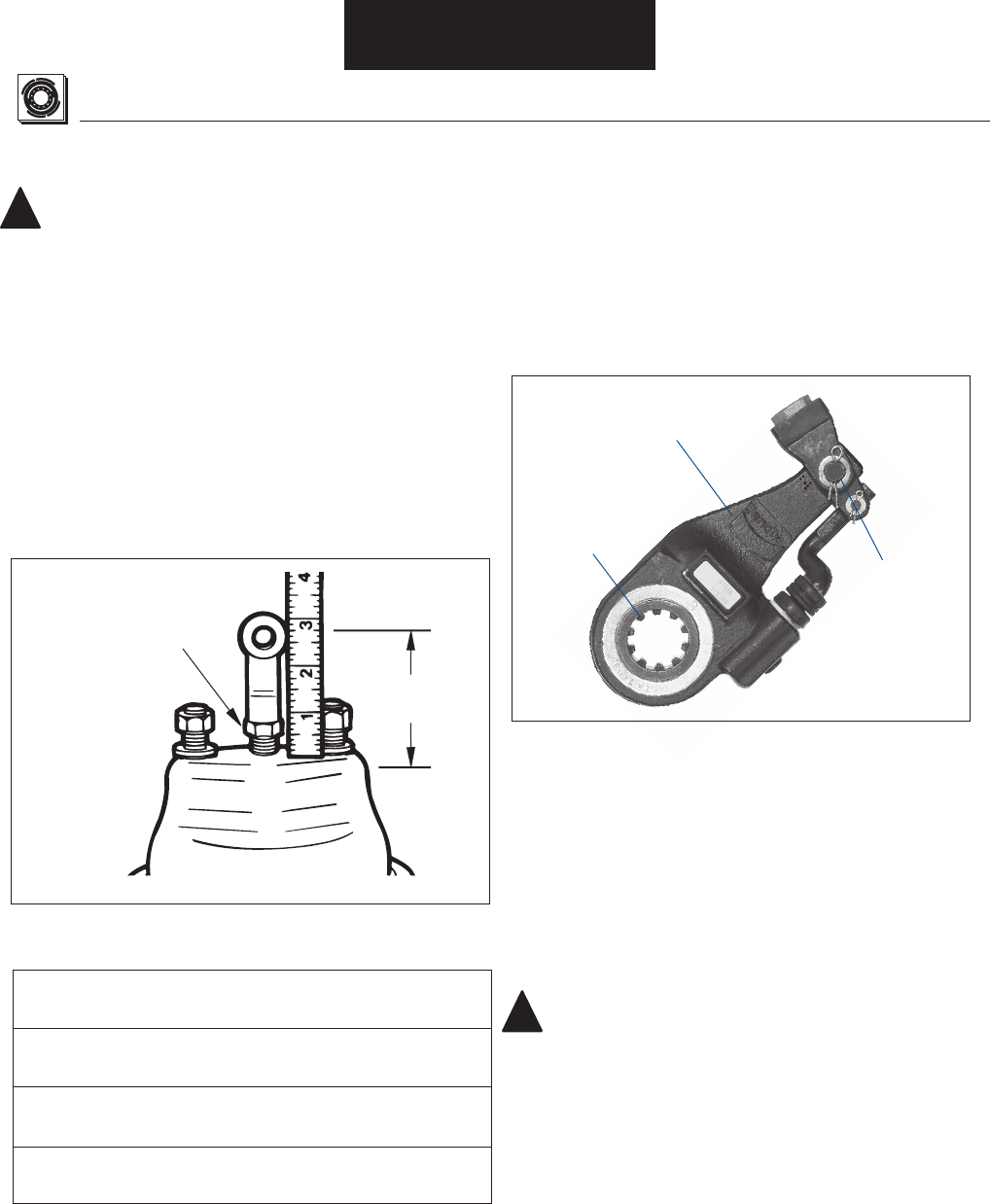
Figure 43. Automatic Slack Adjuster Inspection
Inspection
Figure 42. Air Chamber Inspection
Table 6. Distance: Clevis Pin Hole Centerline to Air Chamber Face
Distance: Clevis Pin Hole
Centerline to Air Chamber Face
--
--
--
Inspection
Air Chamber Inspection
WARNING: -
NOTE:-
-
1.---
----
2. --
--
---
-
3. --
----
-
4. -
Brake Adjuster Inspection
NOTE:--
--
1. -
-
2. --
3. --
-
-
CAUTION:
---
-
--
-
See
Table 6
Tighten Jam Nut
After Adjusting
!
Table 7. Camshaft Bushing Installation Specifi cations
Note:
Brake Model At Cam Head At Brake Adjuster
-- --
--
--
---
-
-- --
---
NOTE:------
--
Camshaft Bushing/Lining Replacement
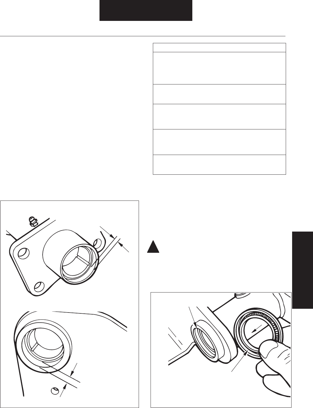
Figure 45. Camshaft Bushing Installation
Figure 44. Air Chamber Bracket Bushing Installation
Repair / Replacement
Spider / Air Chamber &
Brake Adjuster Inspection
Routinely replace lower-cost items such as springs, seals,
bushings, and heavily-worn but unbroken parts since the
damage caused, should these components fail, is far in excess
of their cost.
Camshaft Bushing/Grease Seal Replacement
1.Removal / Disassembly - Air
Chamber Bracket Removal.
2.---
3. -Inspection - Air
Chamber Bracket Inspection.
4.--
---
---
5.------
CAUTION: Seals must be installed as indicated so that
lip side (with spring) of both seals faces toward brake
adjuster end of bracket. Improperly oriented seals may
allow grease to exit camshaft head end of air chamber
bracket and contaminate lining material.
At Brake Adjuster
End, Recess Bushing
22/32" (17.5 mm)
At Cam Head End,
Recess Bushing
9/32" (7.1 mm)
All Brakes, Except Trailer Axles
Lip Side of Both Seals
Must Face Toward Brake
Adjuster End of Bracket
Install Seals Flush
With End of Tube
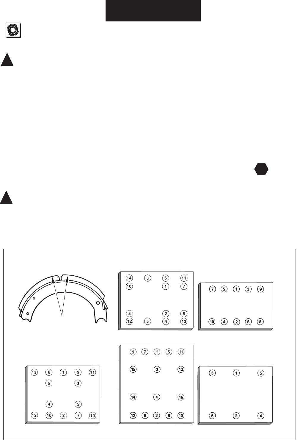
3. --
-
4. ----
NOTE: ----
--
For Riveted Linings:--
---
For Bolted Linings:-
--
--
---
5. ---
-----
--
--
--
Figure 46. Lining Rivet (or Bolt) Tightening Sequence
T
Lining Replacement
!
!
Repair / Replacement
WARNING: -
-
--
See General Information / Lining Material Warning
NOTE:--
Inspection - Shoe, and Lining Inspection.
---
----
-
1. --
2.--
---
CAUTION:--
----
----
-
Positioning Lining Blocks
on ES™ Brake Shoe
ES-165-7 & 8D, L, F Brakes
ES-150-8D,F ES & EB-165-5D, 5L,
6D, 6L Brakes
ES-150-6D
EB-180 Brakes
(Lining Bolted To Shoe)
EB-165-8D, F, L Brakes
EB-165-7D, F, L Brakes
Place Thick
Ends of Blocks
at Shoe Center
ES-165-7H, 7M Only:
Mounting hole patterns at cam and anchor
pin shoe ends are not the same. Match
lining block holes with shoe hole pattern.
Lining RIvet (or Bolt) Tightening Sequence
Spider Installation
SPECIAL NOTE: -
--
-
1---Inspection -
Spider Inspection.
2.---
3.----
NOTE:-
4.--
Dustshield Installation (Two Piece)
NOTE:---
-- Installation / Assembly -
Shoe Installation.
1.------
2.-----
3.---
------
4.
Specifi cations
SPECIAL NOTE
-
-----
------
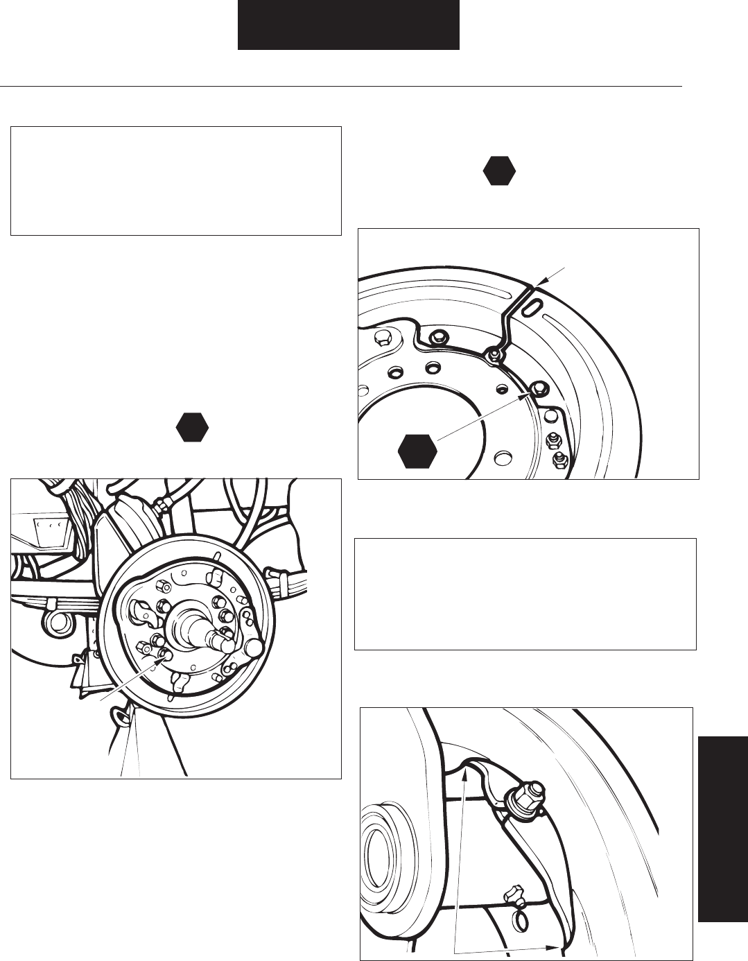
Figure 48. Dustshield Spacing
Figure 49. Designed Interference Fit
T
T
Installation / Assembly
Camshaft Bushing /
Lining Replacement
Figure 47. Installing Spider Mounting Hardware
Tighten All
According to
Manufacturer's
Instructions
Ensure Uniform
1/8" (3mm) Gap
T
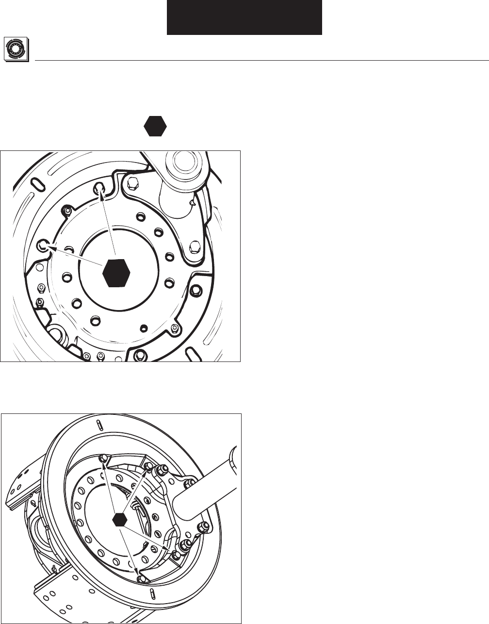
Figure 50. Attaching Screw Location
T
Dustshield Installation (One Piece)
Installation / Assembly
1.---
2.
Specifi cations Chart
T
T
Air Chamber Bracket Installation
EB/ES-150-4L Brake
1.---
Removal/Disassembly - Air Chamber Bracket Removal.
2.---
-
3.---
--
NOTE: -
-General Information - Parts Nomenclature.
CAUTION: -
---
4.-Specifi cations
5.-----
6.Specifi cations
T
T
T
Figure 51. Air Chamber Bracket Mounting Hardware
!
T
T
Installation / Assembly
Spider / Dustshield
Installation
Air Chamber Bracket Installation
1.---
Inspection - Air Chamber Bracket Inspection.
2.--
-
3.---
4Specifi cations
5.--
-
6.---
-
7.-Specifi cations
8.--
Specifi cations
T
T
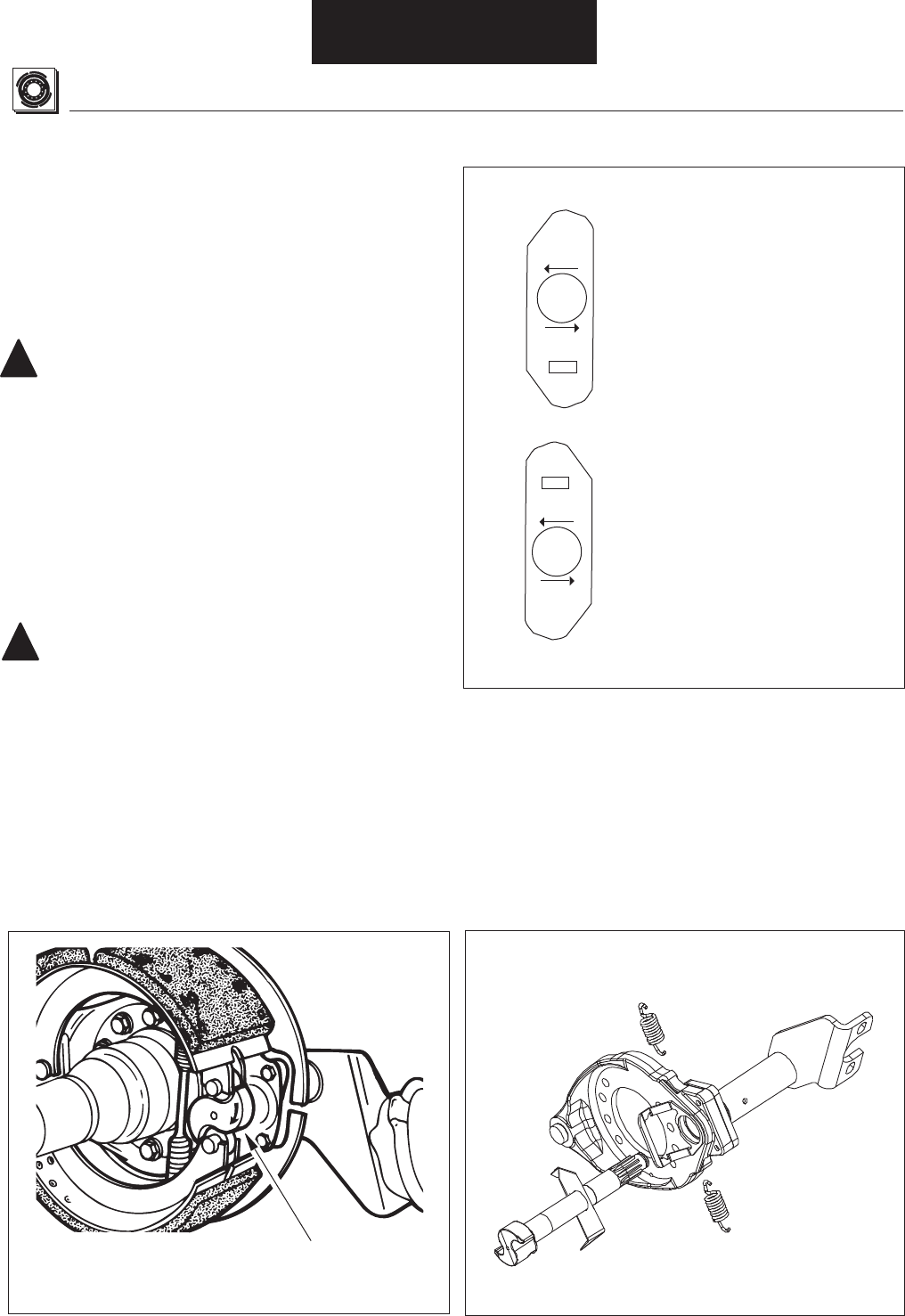
Figure 53. Cam Head Washer Installation
Camshaft Installation
!
!
Figure 52. Camshaft Installation
Installation / Assembly
1.---
-nspection - Camshaft Inspection.
NOTE: --
-----
CAUTION:--
-
2. --
-
--
3.--
--
CAUTION:
-
4.---
SPECIAL NOTE: --
--
-
---
SPECIAL NOTE-
--
----
--
ES-165-5,6,7D,L
Rotate Camshaft
Tow ard Pushrod
Extension . . .
. . . Roller Should
Ride Up on Convex
Side of Cam Head
Cast Spider. Position
Cam Head Washer
Under Cam Head With
“CAST SPIDER” Arrow
Pointing Toward Center
of Spider.
Note For ES-150-8D & 6D:
position cam head washer
under cam head with
"CAST SPIDER" arrow
pointing away from center
of spider.
Stamped Spider. Position
Cam Head Washer
Under Cam Head With
“STAMPED SPIDER” Arrow
Pointing Toward Center
of Spider.
STAMPED
SPIDER
CAST
SPIDER
STAMPED
SPIDER
CAST
SPIDER
5.--
--
NOTE:--
------
6. ---
7. ---
8.-
9.
-
-
10.-
--
CAUTION: -
--
CAUTION: -
--
---
Figure 55. Brake Adjuster End Play Check
Figure 56. Brake Adjuster Lubrication and Adjustment
Figure 54. Shim Washer and Snap Ring Installation
!
!
Installation / Assembly
Bracket/Camshaft/Washer
Installation
SPECIAL NOTE: -
--
----
--
Cam Head Washer Installation
Brake Adjuster Installation
1.-
2.--
--
3.---
4.--
-
Install
Snap Ring
Camshaft
Shim Washers
Thick Washer
with Large Hole
Here
Move Camshaft. Note
Maximum Deflection
No Less Than 0.005" (0.13 mm)
No More Than 0.025" (.65 mm)
Lubricate Slack
Adjuster With
Chassis Grease
Rotate Adjuster Nut
Until Brake Adjuster is
Aligned With Clevis Hole.

Shoe and Lining Installation
Table 8. Shoe Installation Procedure Index
Installation / Assembly
11.--
Inspection - Air Chamber Inspection.-
--
12.---
----
13. ---
Brake Model Page Number
EB-150-4L
44
EB-165-5D 46
EB-165-5L 46
EB-165-6D 46
EB-165-6L 46
EB-165-7D 46
EB-165-7L 46
EB-165-7F 46
EB-165-8D 46
EB-165-8F 46
EB-165-8L 46
EB-180-7R 46
ES-150-4L 44
ES-150-6D 45
ES-150-8D 45
ES-150-8F 45
ES-165-5D 46
ES-165-5L 46
ES-165-6D 46
ES-165-6L 46
ES-165-7D 46
ES-165-7F 46
ES-165-7H 50
ES-165-7L 46
ES-165-7M 48
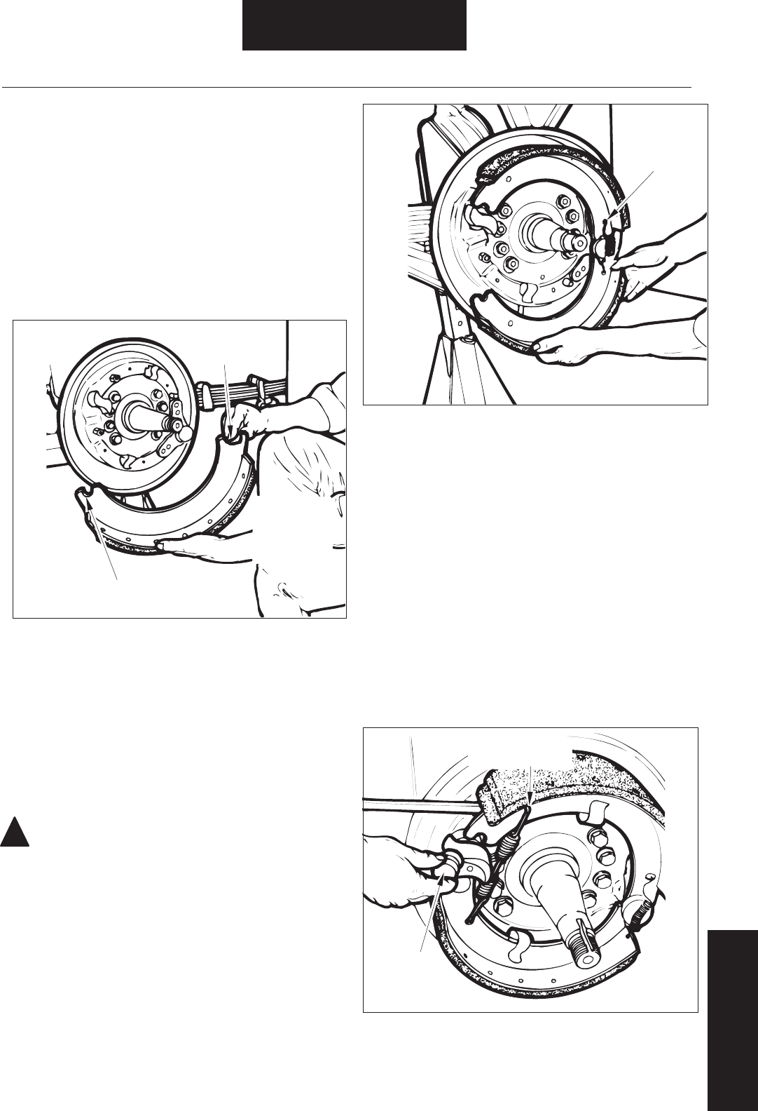
Figure 58. Shoe Retaining Spring Installation
Figure 59. Shoe Return Spring and Roller Installation
!
Installation / Assembly
Brake Adjuster/Shoe and
Lining Installation
Shoe and Lining Installation
---
--
---
EB/ES-150-4L Brake
1.
----
NOTE:General Information - Parts Nomenclature
-
2.----
CAUTION:-
3.-
----
4.-
--
5.--
6.---
7.-
8.--
-
9.--
----
10.-----
Figure 57. Shoe Web Lubrication
Anchor Pin
Recess
Use Only a
Light Film of
Specified
Grease
Roller Recess
Hook Spring
into Shoe
Web Hole
Install New
Return Spring
Install
Rollers
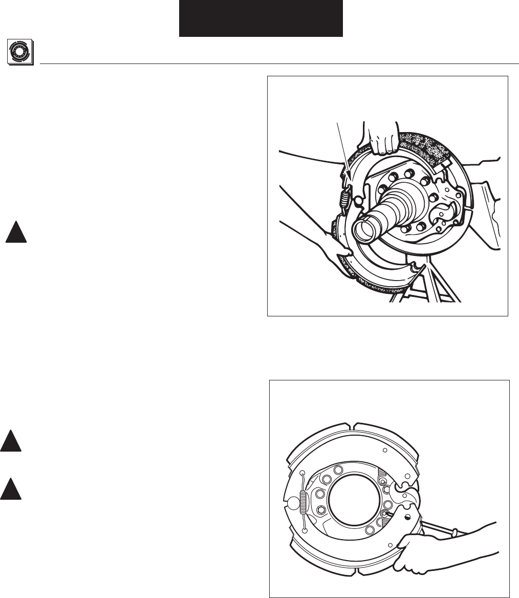
Figure 60. Upper and Lower Shoe Positioning
Shoe And Lining Installation
!
Figure 61. Shoe Return Spring Installation
!
!
Installation / Assembly
NOTE: --
-
ES-150-8D, F&6D
1.Inspection & Repair / Replacement
--
--
2.---
----
CAUTION:-
-
3.
4.--
---
---
5. -
CAUTION:
--
WARNING: -
-
--
See General Information / Lining Material Warning
6.--
--
--
NOTE: --
Do Not Lubricate:
With Retainer Springs
Installed, Position
Upper and Lower Shoes
Around Anchor Pin
Stretch Spring Using
Suitable Tool As Shown

Figure 62. Upper and Lower Shoe Positioning
Figure 63. Shoe Return Spring Installation
!
!
Installation / Assembly
Shoe and Lining
Installation
All EB (except EB-150-4L) and ES-165 5/6/7/8D,F,L
NOTE: --
-
1. Inspection & Repair / Replacement
--
--
2. ---
----
----
CAUTION: -
Do Not Lubricate:
-
3. -
-
4.-
WARNING: -
-
--
See General Information / Lining Material Warning
5. --
NOTE: -
With Retainer Springs
Installed, Position
Upper and Lower Shoes
Around Anchor Pin
ES-165-D,L,F Only:
Stetch Spring Using Suitable
Tool Positioned as Shown
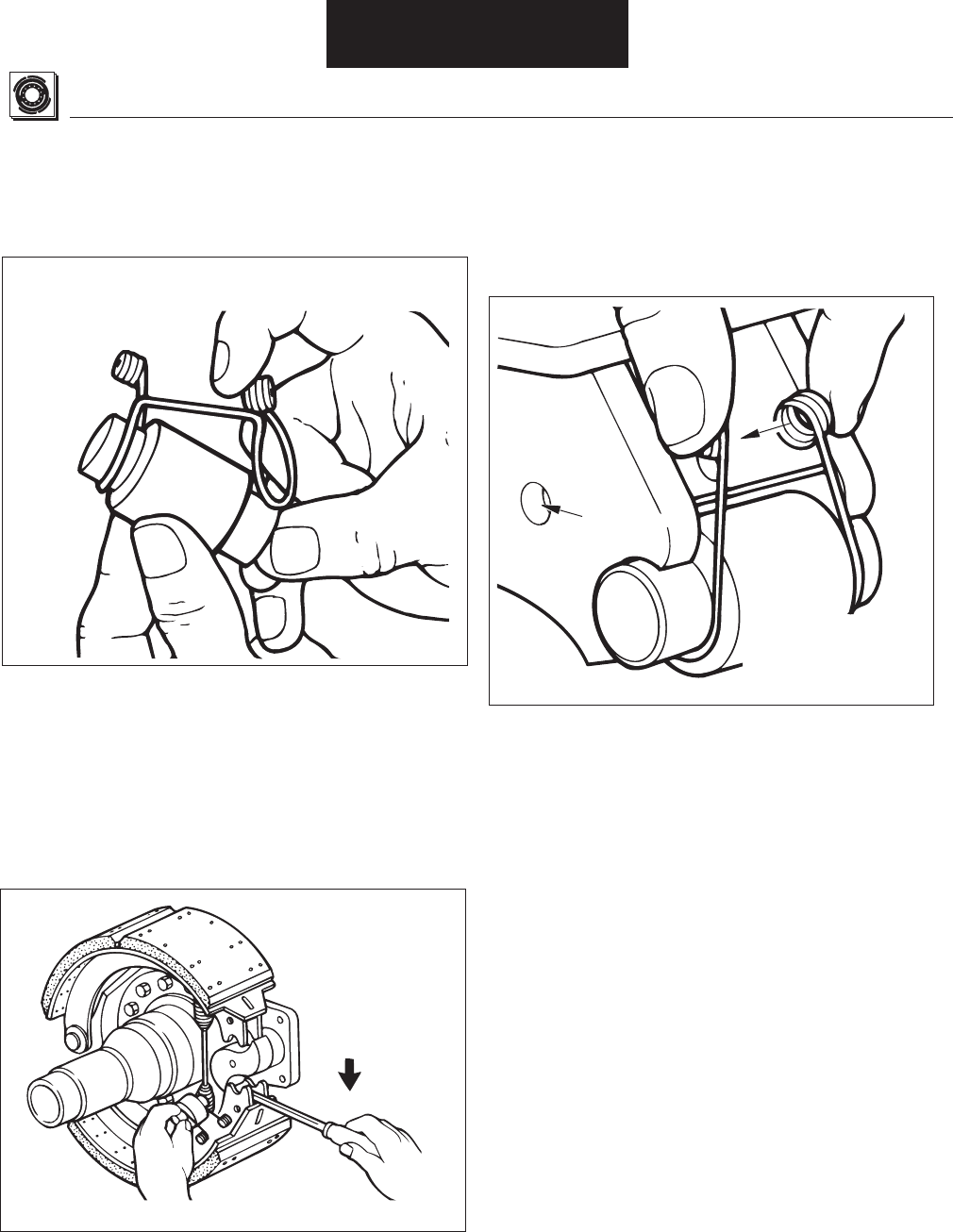
Figure 65. Shoe Return Spring Installation
Shoe And Lining Installation
Figure 64. Roller Retainer Installation
Installation / Assembly
6. For ES-165 5/6/7/8D, L, F, ES-150-4D, ES-150-8D, F & 6D only:
-----
7. --
------
--
NOTE: --Inspection-
Drum Inspection.
8. For ES-165 5/6/7/8D, L, F, ES-150-4D, ES-150-8D, F & 6D only:
----
--
-
-
NOTE: -----
Figure 66. Retainer Installation
Install Retainer
on Roller
Web
Hole
Install Retainer
Loops in Shoe
Web Holes
Stretch
Return Spring,
Install Roller
And Retainer
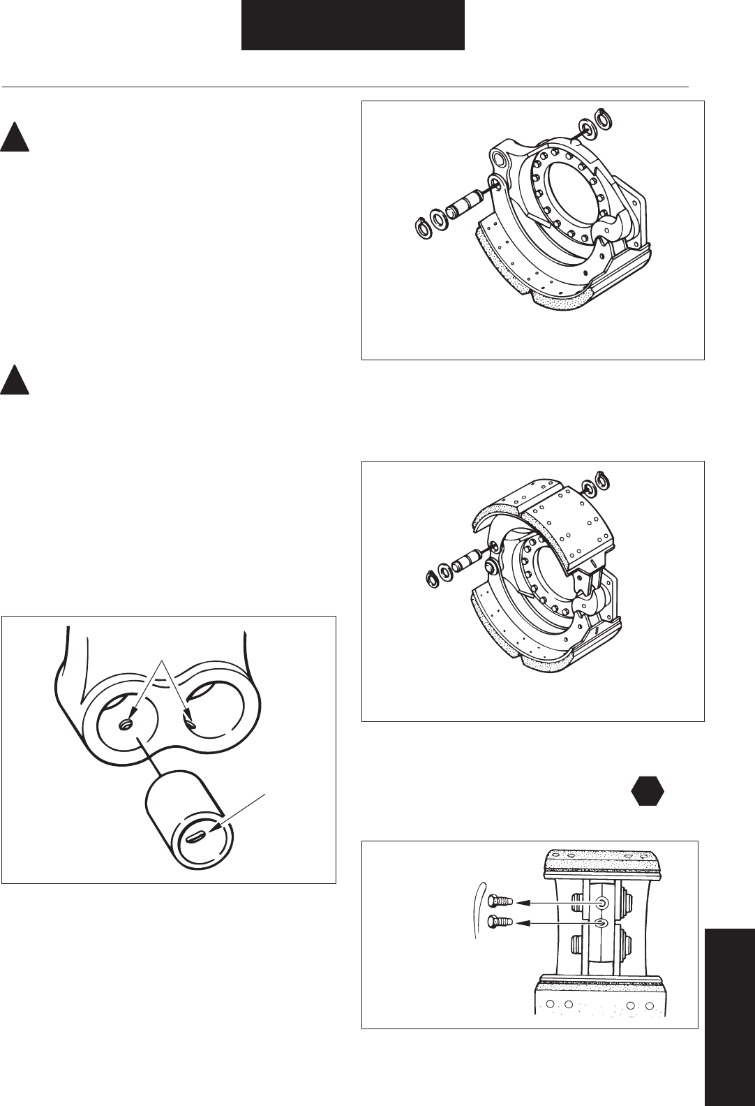
Figure 68. Lower Shoe and Anchor Pin Installation
Figure 70. Cap Screw Installation
Figure 69. Upper Shoe and Anchor Pin Installation
Figure 67. Anchor Pin Bushing Installation
T
!
!
Installation / Assembly
Shoe Installation
WARNING: -
-
--
See General Information / Lining Material Warning
ES-165-7M Heavy Duty Brake
1. Inspection & Repair / Replacement
--
--
2.---
--
--
CAUTION: -
Do Not Lubricate:
-
3. -
Removal/Disassembly - Shoe Removal
---
4. --
5. --
---
6. ---
7. --
Specifi cations-
Screw Holes
in Spider
Slot in
Bushing
Position Bushing
to Align Spider
Screw Hole With
Bushing Slot
Position Lower Shoe on Spider and Install
Anchor Pin, Washers and Retaining Rings
Place Upper Shoe on Spider and Install
Anchor Pin, Washers and Retaining Rings
Install Cap
Screws and
Lockwire
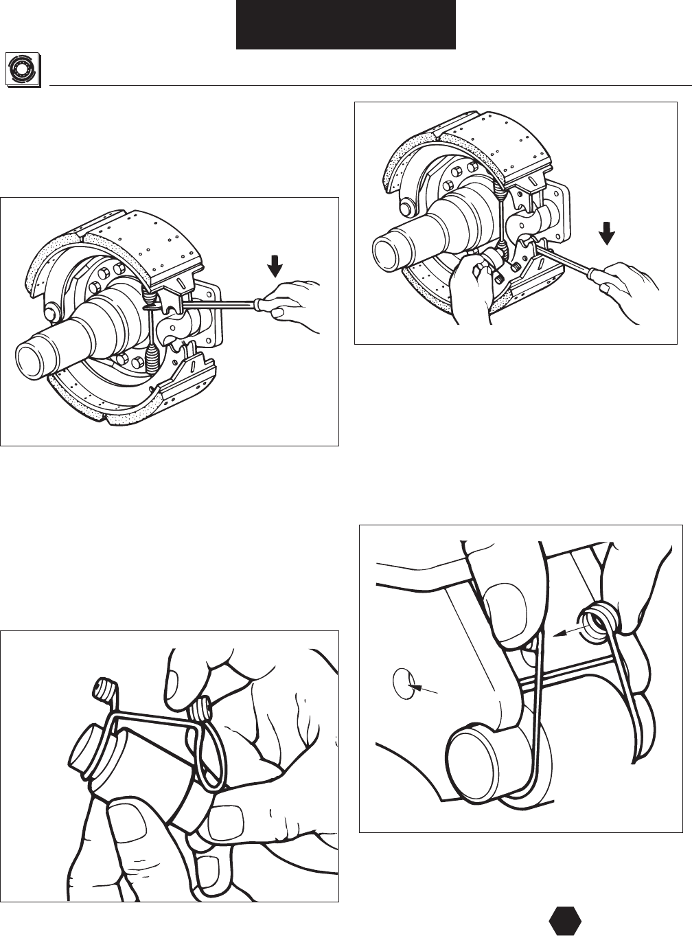
Figure 71. Shoe Return Spring Installation
Figure 73. Roller and Retainer Installation
Figure 72. Roller Retainer Installation
Shoe Installation
Figure 74. Retainer Installation
T
Installation / Assembly
8. --
NOTE: -
NOTE: Inspection - Drum Inspection.
9.------
10. --
--------
11.--
--
-
--
12.
13. ---
Specifi cations
Stretch Spring
Using Suitable
Tool Positioned
As Shown
Install Retainer
on Roller
Stretch
Return Spring,
Install Roller
And Retainer
Web
Hole
Install Retainer
Loops in Shoe
Web Holes
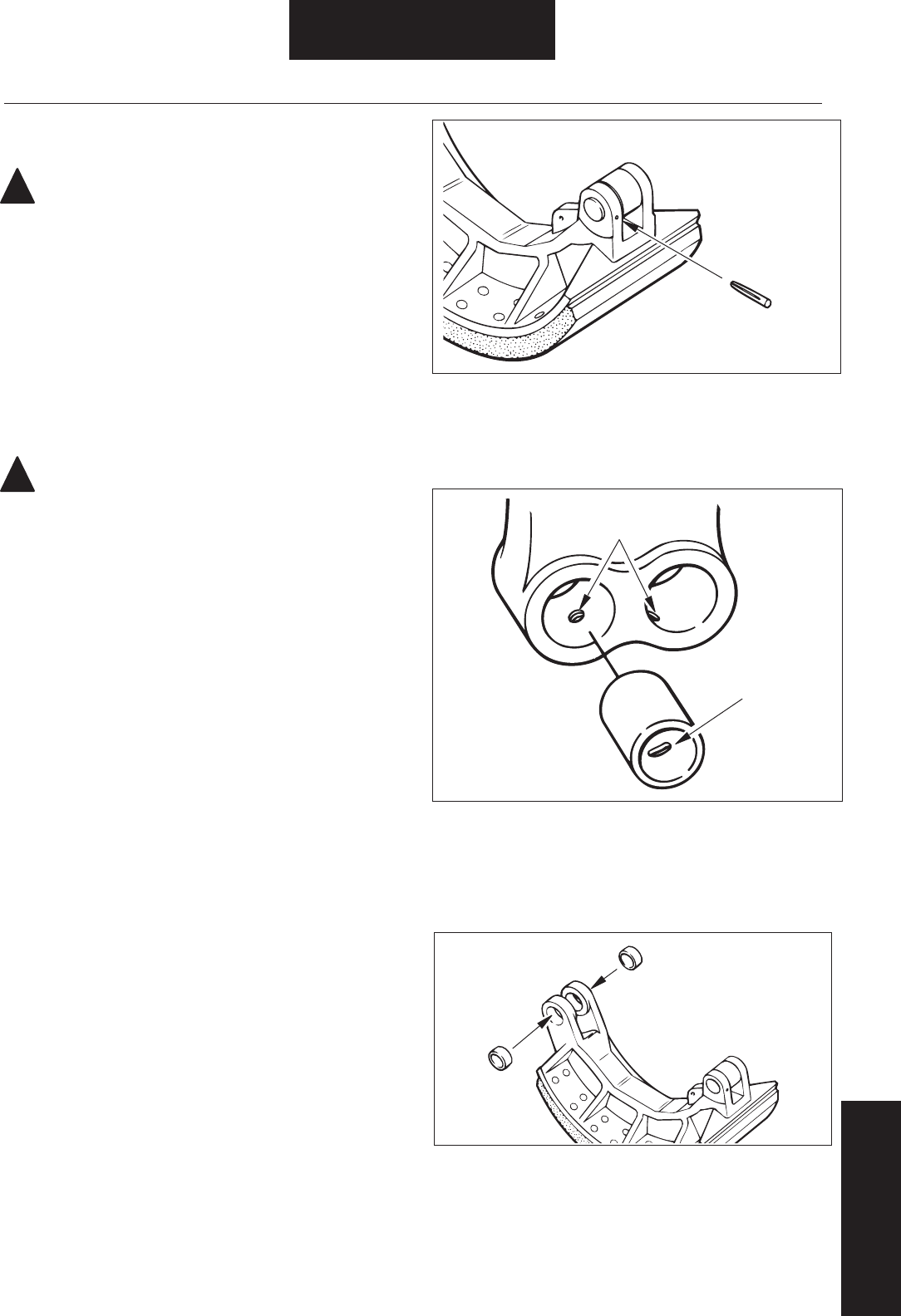
Figure 75. Groove Pin Installation
Figure 76. Spider Anchor Pin Bushing Installation
!
!
Figure 77. Shoe Anchor Pin Bushing Installation
Shoe Installation
Installation / Assembly
ES-165-7-H Severe Duty Brake
WARNING: -
-
--
See General Information/lining Material Warning
1. Inspection & Repair / Replacement
--
--
2. ---
--
--
CAUTION:-
Do Not Lubricate:
-
NOTE:-----
3. ----
---
4. -
Removal/Disassembly - Shoe Removal
---
5.
6. --
7. -----
Screw Holes
in Spider
Slot in
Bushing
Position Bushing
to Align Spider
Screw Hole with
Bushing Slot
Press Bushings
in Shoe
Secure Roller Pin
with Groove Pin
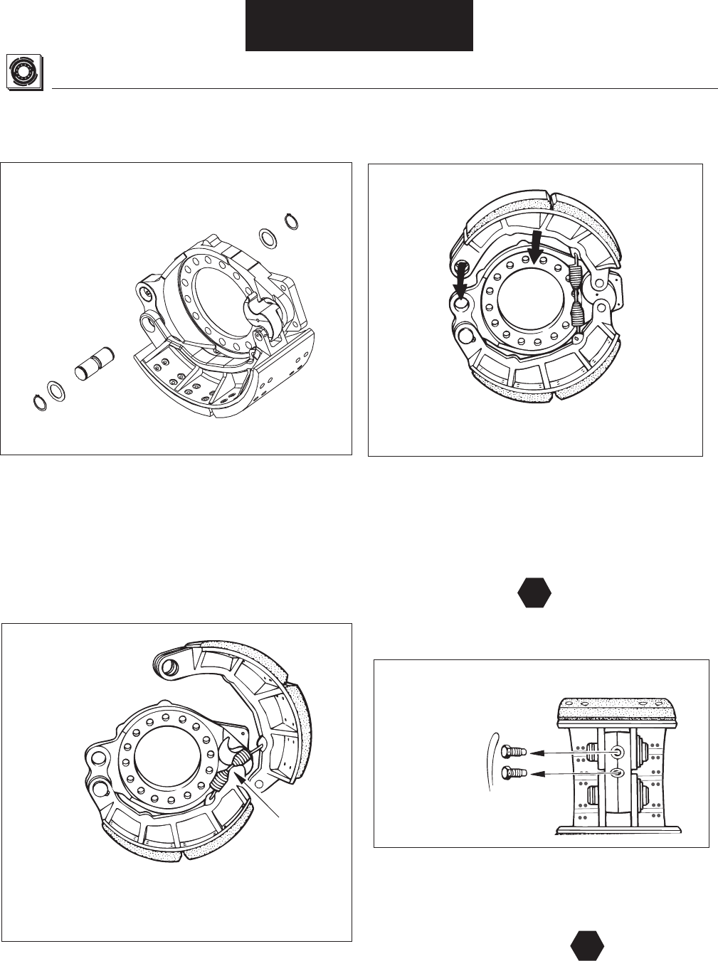
Figure 78. Lower Shoe Positioning
Figure 79. Upper Shoe Positioning
Figure 80. Upper Shoe Installation
Shoe Installation
T
Figure 81. Lower Shoe and Anchor Pin Installation
T
Installation / Assembly
8. -
9. ------
10. -----
11. --
-
12. ---
Specifi cations
Return
Spring
Position Upper Shoe on Spider,
Connect Return Spring (With Shoe
End Disengaged from Cam)
Complete Installation of Upper Shoe
--

Fastener Torque Specifi cations
All EB/ES 165, 150-4D, 150-8D, F & 6D
Fastener Torque
lbs./ft. – lbs./in. N.m
-- -
- -
- -
- -
-
-
- --
-
EB/ES-150-4L
Fastener Torque
lbs./ft. – lbs./in. N.m
- -
-
- -
-
-
- -
Key Dimensional Specifi cations
Minimum Lining ThicknessShoe and Lining Inspection
--
--
----
---
--
Air Chamber/Applied & Free Stroke
Maximum
Maximum Desired
Air Chamber Size Applied Stroke Free Stroke
Specifi cation Chart
Specifi cations
Wheel Bearing
Adjustment/Lubrication

Specifi cations

Specifi cations

Specifi cations

BW
7258 ©2008 Bendix Spicer Foundation Brake LLC • 04/08 • All Rights Reserved • Printed in U.S.A.
901 Cleveland Street • Elyria, Ohio 44035 •1-866-610-9709 • www.foundationbrakes.com
For more information, talk to your Bendix
representative, call 1-866-610-9709 or visit
www.foundationbrakes.com.
