Bendix Bw7274 Users Manual 165sman2
2015-04-02
: Bendix Bendix-Bw7274-Users-Manual-682170 bendix-bw7274-users-manual-682170 bendix pdf
Open the PDF directly: View PDF ![]() .
.
Page Count: 26
- Table of Contents
- Identification
- Components - Standard & XL
- Components - Cast Shoe Series
- Components - 16.5" XL II
- Components - 16.5" P Series
- General Precautions
- Preventative Maintenance
- Brake Disassembly
- Inspection of Parts
- Brake Assembly
- Troubleshooting Chart, Foundation Brake
- Troubleshooting Chart, Shoe & Lining
- Troubleshooting Chart, Brake Drum
- Reline Procedure
For the most current information, visit the Roadranger web site at www.roadranger.com
16.5" Series S-Cam Cast
XTRALIFE TM P-Series
XTRALIFE II TM
Dana®Spicer®Brakes
Service Manual BRSM-0890 October 1997

TABLE OF CONTENTS
i
GENUINE SPICER SERVICE PARTS
Should a brake assembly require replacement component parts, it is recommended that Spicer
Brake Service Parts be used. Spicer Brake Service Parts are manufactured under the same rigid
specification as are original equipment brake components. This assures the customer who uses
genuine Spicer service parts, maximum reliability for a Spicer Brake assembly. They may be
obtained through your vehicle manufacturer. The use of non-original Spicer service parts may
cause premature compontent failure and may void the warranty.
The items included in this book are currently being offered as service parts at the time of
printing. The part numbers and illustrations are provided specifically for reference purposes
only. Therefore, Spicer reserves the right to update this manual without notice or liability.
Identification ..................................................................... 2
Brake Components (Standard/Xtralife) ...................... 3
Brake Components (Cast Series).................................. 4
Brake Components (XL II Series).................................. 5
Brake Components (“P” Series) .................................... 6
General Precautions ......................................................... 7
Preventative Maintenance............................................... 9
Brake Disassembly ............................................................ 11
Inspection of Parts ........................................................... 12
Brake Assembly ................................................................. 15
Trouble Shooting Charts ................................................. 18
Reline Procedure ............................................................... 21
97 170
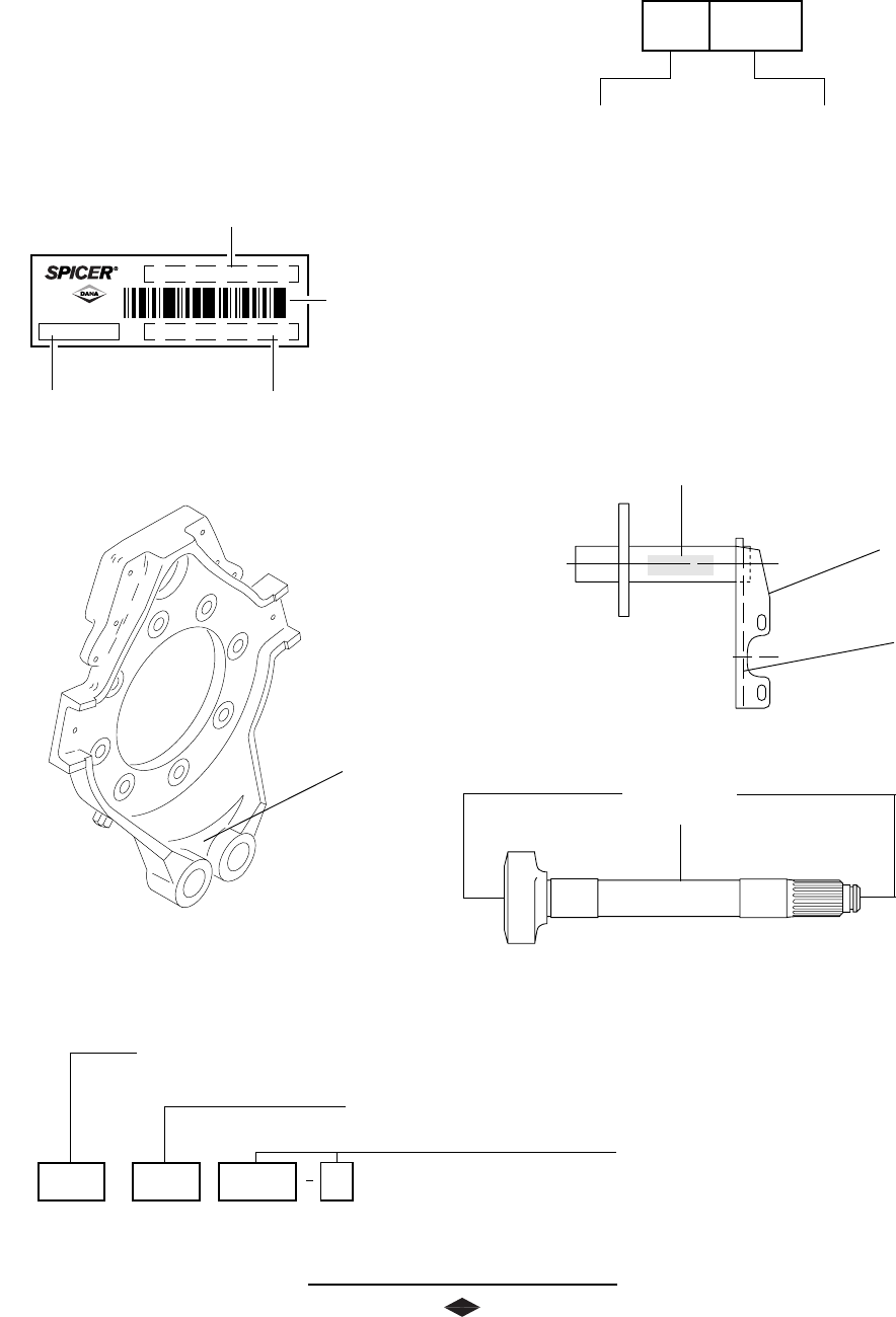
IDENTIFICATION
2
The brake assembly may be identified by a tag which is
located on the camshaft bracket cylinder, near the
grease fitting.
The mylar brake assembly tag contains the following:
Dana assembly number, bar coded customer assembly
number, and a numeric customer assembly number.
DAY OF YEARMODEL YEAR
JULIAN DATE CODE
Two other markings that may be used to identify a
Spicer Brake assembly are located on the assembly's
components. "Spicer" will be cast into the spider
assembly just above the anchor pins. Also, the inside of
the chamber bracket arm contains the following stamped
part information: "Spicer", julian date code, and the part
number.
Brake Assembly Tag
CUSTOMER
ASSEMBLY
NUMBER
CUSTOMER
BAR CODE
NUMBER
165 WD 000 0
MODEL IDENTIFICATION NUMBERING SYSTEM
Alphabetical Code
(i.e., WD = Brake Assembly)
Model (165 = 16.5" Brake)
(150 = 15" Brake)
DANA
ASSEMBLY NUMBER
Sequential Assembly
Numbers
Camshaft Bracket
CHAMBER
BRACKET ARM
STAMPED PART
INFORMATION
BRAKE ASSEMBLY TAG
Camshaft
STAMPED PART
INFORMATION
(IN ONE OF THESE AREAS)
"SPICER"
Spider
BUILD DATE
(APR 1997 AND LATER)
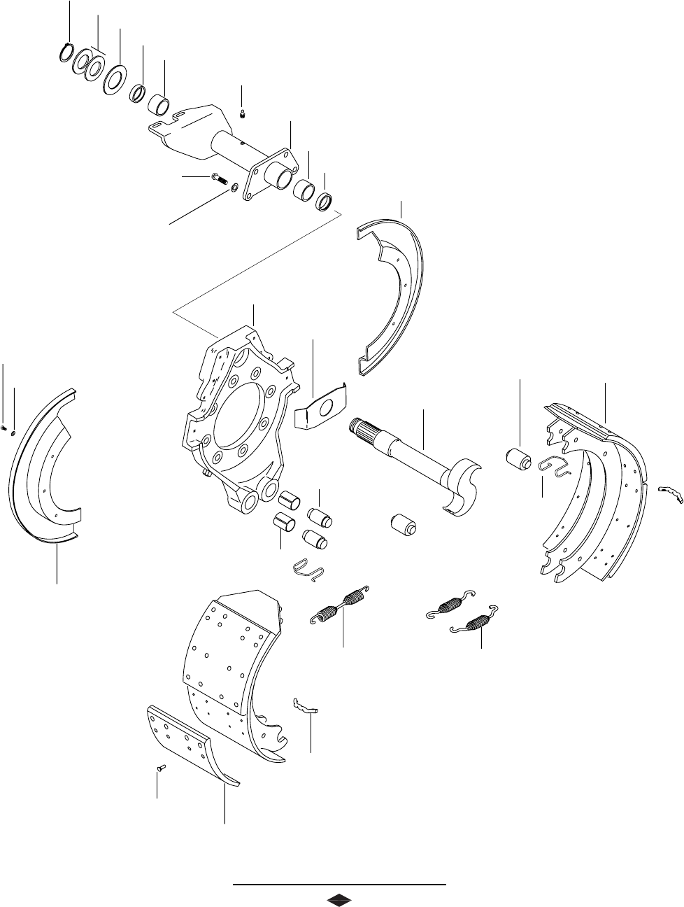
BRAKE COMPONENTS
STANDARD/ XTRALIFE 16.5"
3
Retaining Ring
Camshaft Adjusting
Washers (Shims)
Grease Fitting
Air Chamber
Bracket Assembly
Grease Seal
Steel Spacer
Camshaft Bushing
Camshaft Bushing
Bracket Mounting Bolt
(70 - 80 Lb-Ft)
(95 - 108 N-m)
Lock Washer
Grease Seal
Steel Spacer Plate
Camshaft
Shoe Return Spring
Cam Roller
Spider
Lining
Shoe and Lining
Assembly
Brake Lining
Rivet
Lock Washer
Dustshield Mounting Bolt
3/8 in. - 16
(20 - 28 Lb-Ft)
(27 - 38 N-m)
Return Spring Pin
Retainer Springs
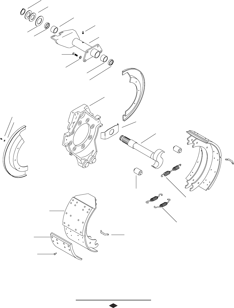
BRAKE COMPONENTS
16.5" CAST SHOE SERIES
Retaining Ring
Camshaft Adjusting
Washers (Shims)
Grease Fitting
Air Chamber
Bracket Assembly
Grease Seal
Steel Spacer
Camshaft Bushing
Camshaft Bushing
Bracket Mounting Bolt
(70 - 80 Lb-Ft)
(95 - 108 N-m)
Lock Washer
Grease Seal
Lock Washer
Dust Shield Half
Spider
Steel Spacer Plate
Camshaft
Anchor Pin Bushing
Grease Fitting
Brake Lining Nut
(15-17 Lb-Ft)
(20-23 N-m)
Shoe Return Spring
Cam Roller
Anchor Pin
Anchor Pin
Retainer Clip
Brake Lining
Bronze Bushing
Anchor Pin
Retainer Clip
Lining
Shoe and Lining
Assembly
Brake Lining
Bolt
4
Dustshield Mounting Bolt
3/8 in. - 16
(20 - 28 Lb-Ft)
(27 - 38 N-m)
Washer
Washer
Lock Washer
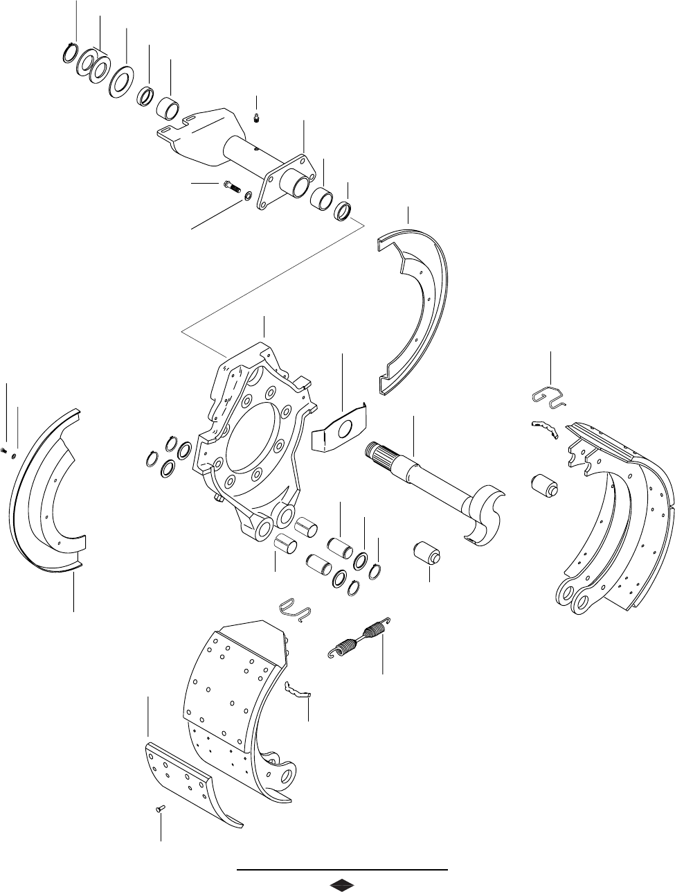
BRAKE COMPONENTS
16.5" XL II SERIES BRAKE
Retaining Ring
Camshaft Adjusting Washer
Steel Spacer
Grease Seal
Camshaft Bushing
Camshaft Bracket
Camshaft Bushing
Grease Seal
Spider
Steel Spacer Plate
Camshaft
Shoe and
Lining Assembly
Cam Roller
Shoe Retainer Spring
Shoe Return Spring
Anchor Pin
Anchor Pin Bushing
Return Spring Pin
Lining
Dust Shield (Half)
Dust Shield (Half)
Bracket Mounting Bolt
(70 - 80 Lb-Ft)
(95 - 108 N-m)
Lock Washer
Dustshield Mounting Bolt
3/8 in. - 16
(20 - 28 Lb-Ft)
(27 - 38 N-m)
Grease Fitting
Lock Washer
Brake Lining Rivet
Cam Roller
Retainer Clip
5
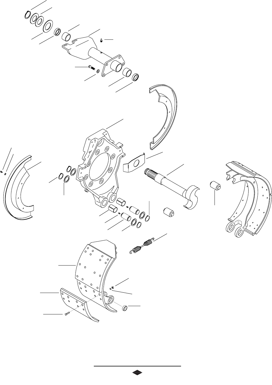
BRAKE COMPONENTS
16.5" P SERIES BRAKE
Retainer Ring
Camshaft Adjusting Washer
Steel Spacer
Grease Seal
Camshaft Bushing
Camshaft Bracket
Camshaft Bushing
Grease Seal
Spider
Steel Spacer Plate
Camshaft
Cam Roller
Shoe Return Spring
Anchor Pin
Anchor Pin Bushing
Return Spring Pin
Lining
Dust Shield (Half)
Dust Shield (Half)
Bracket Mounting Bolt
(70 - 80 Lb-Ft)
(95 - 108 N-m)
Lock Washer
Dustshield Mounting Bolt
3/8 in. - 16
(20 - 28 Lb-Ft)
(27 - 38 N-m)
Grease Fitting
Lock Washer
Brake Lining Rivet
Cam Roller
Retainer Clip
6
Washer
Snap Ring
7
GENERAL PRECAUTIONS
All Spicer original equipment or service parts for
steering and drive axle brakes are manufactured using
non-asbestos brake lining. It is recommended that
original Spicer service parts be used when brake mainte-
nance is necessary.
SAFETY PRECAUTIONS
Proper service and repair of vehicle components is
important to the safe and reliable operation of all motor
vehicles. This applies particularly to brakes such as the
ones described in this manual. The procedures recom-
mended and described in this manual are tested,
effective methods for performing service operation.
Follow each procedure closely, making use of both the
text and pictures. Some of these service procedures
show the use of certain tools designed especially for the
operation being performed. It is not mandatory that
these tools be used; they are shown only as preferred
means of performing the operation. It is not practical to
anticipate and advise the service trade of all possible
alternate service methods, and of all possible hazardous
consequences that could result from any particular
method. Accordingly, anyone who uses a service
procedure or tool different than shown must insure that
their safety, and that the vehicle’s safety will not be
jeopardized by the service method selected.
CA CA
CA CA
CAUTION:UTION:
UTION:UTION:
UTION: When wWhen w
When wWhen w
When working on or arorking on or ar
orking on or arorking on or ar
orking on or around airound air
ound airound air
ound air
brbr
brbr
brakak
akak
ake se s
e se s
e syy
yy
ystst
stst
stems and componentems and component
ems and componentems and component
ems and components, the follos, the follo
s, the follos, the follo
s, the followingwing
wingwing
wing
prpr
prpr
precautions should be observecautions should be observ
ecautions should be observecautions should be observ
ecautions should be observed:ed:
ed:ed:
ed:
1.1.
1.1.
1. Always block vehicle wheels. Stop engine when
working under a vehicle. Depleting vehicle air
system pressure may cause vehicle to roll. Keep
hands away from chamber push rods and slack
adjusters; they may automatically apply as system
pressure drops.
2.2.
2.2.
2. Never connect or disconnect a hose or line con-
taining air pressure. It may whip as air escapes.
IMPORIMPOR
IMPORIMPOR
IMPORTT
TT
TANTANT
ANTANT
ANT
READ THIS SECTION BEFORE STREAD THIS SECTION BEFORE ST
READ THIS SECTION BEFORE STREAD THIS SECTION BEFORE ST
READ THIS SECTION BEFORE STARAR
ARAR
ARTINGTING
TINGTING
TING
ANY SERANY SER
ANY SERANY SER
ANY SERVICE PROCEDURESVICE PROCEDURES
VICE PROCEDURESVICE PROCEDURES
VICE PROCEDURES
Never remove a component or pipe plug unless you
are certain all system pressure has been depleted.
3.3.
3.3.
3. Never exceed recommended air pressure and always
wear safety glasses when working with air pressure.
Never look into air jets or direct them at anyone.
4.4.
4.4.
4. Never attempt to disassemble a component until
you have read and understand recommended
procedures. Some components contain powerful
springs and injury can result if not properly
disassembled. Use only proper tools and observe
all precautions pertaining to use of those tools.
5.5.
5.5.
5. Use only genuine Spicer replacement parts and
components.
A. A.
A. A.
A. Only components, devices, mounting and
attaching hardware specifically designed for use
in air brake systems should be used.
B. B.
B. B.
B. Replacement hardware, tubing, hose, fittings, etc.
should be of equivalent size, type, length and
strength as the original equipment.
C. C.
C. C.
C. Make certain that when replacing tubing or hose,
all supports, clamps or suspending devices that
were originally installed by the vehicle manufac-
turer are reinstalled.
6.6.
6.6.
6. Devices with stripped threads or damaged parts
should be replaced. Repairs requiring machining
should not be attempted.
CAUTION
BREATHING BRAKE DUST MAY BE HAZARDOUS TO YOUR HEALTH AND
MAY CAUSE SERIOUS RESPIRATORY OR OTHER BODILY HARM.
FOLLOW 0.S.H.A. STANDARDS FOR PROPER PROTECTIVE DEVICES TO BE USED
WHEN WORKING WITH BRAKE MATERIALS.
BRAKE LININGS CONTAIN NON-ASBESTOS FIBERS
AVOID CREATING DUST
DO NOT REMOVE BRAKE DRUM WITHOUT PROPER PROTECTIVE EQUIPMENT.
DO NOT WORK ON LININGS WITHOUT PROPER PROTECTIVE EQUIPMENT.
DO NOT REPLACE LININGS WITHOUT PROPER PROTECTIVE EQUIPMENT.
DO NOT ATTEMPT TO SAND, GRIND, CHISEL, FILE, HAMMER OR ALTER BRAKE
LININGS IN ANY MANNER WITHOUT PROPER PROTECTIVE EQUIPMENT.
8
PREPARATION
1.1.
1.1.
1. Park vehicle on a level surface and prevent
movement by means other than the brakes.
2.2.
2.2.
2. If equipped with spring brakes, cage the spring on
all axles to be worked on.
3.3.
3.3.
3. Raise the axle, to be worked on until the tires
clear the ground. Support axle with heavy duty
jack stands.
4. "Back-off " slack adjuster by turning adjusting nut
until the brake shoes are fully retracted.
CACA
CACA
CAUTION: RUTION: R
UTION: RUTION: R
UTION: Rockwockw
ockwockw
ockwell Autell Aut
ell Autell Aut
ell Auto Slacks ro Slacks r
o Slacks ro Slacks r
o Slacks requirequir
equirequir
equire the pae the pa
e the pae the pa
e the pawlwl
wlwl
wl
aa
aa
assemblssembl
ssemblssembl
ssembly ty t
y ty t
y to be ro be r
o be ro be r
o be remoemo
emoemo
emovv
vv
ved befored befor
ed befored befor
ed before turning the adjuste turning the adjust
e turning the adjuste turning the adjust
e turning the adjust--
--
-
ing ning n
ing ning n
ing nut.ut.
ut.ut.
ut.
WW
WW
WARNING: NeARNING: Ne
ARNING: NeARNING: Ne
ARNING: Nevv
vv
ver wer w
er wer w
er work under a vork under a v
ork under a vork under a v
ork under a vehicle supporehicle suppor
ehicle supporehicle suppor
ehicle supportt
tt
teded
eded
ed
onlonl
onlonl
only by b
y by b
y by a jack. Alwy a jack. Alw
y a jack. Alwy a jack. Alw
y a jack. Alwaa
aa
ayy
yy
ys use a jack sts use a jack st
s use a jack sts use a jack st
s use a jack stand.and.
and.and.
and.
GENERAL PRECAUTIONS (CONTINUED)
5.5.
5.5.
5. Remove wheels and drums using the procedures
specified in the vehicle maintenance manual.
WW
WW
WARNING: The long tARNING: The long t
ARNING: The long tARNING: The long t
ARNING: The long term effecterm effect
erm effecterm effect
erm effects of es of e
s of es of e
s of exposurxposur
xposurxposur
xposure te t
e te t
e to non-o non-
o non-o non-
o non-
aa
aa
asbesbe
sbesbe
sbestst
stst
stos haos ha
os haos ha
os has nos no
s nos no
s not been det been de
t been det been de
t been dett
tt
termined. Aermined. A
ermined. Aermined. A
ermined. Avv
vv
void croid cr
oid croid cr
oid creaea
eaea
eatingting
tingting
ting
dust when perdust when per
dust when perdust when per
dust when performing service on brforming service on br
forming service on brforming service on br
forming service on brakak
akak
ake ae a
e ae a
e assembliessemblie
ssembliessemblie
ssemblies.s.
s.s.
s.
ExEx
ExEx
Excece
cece
cessivssiv
ssivssiv
ssive ee e
e ee e
e exposurxposur
xposurxposur
xposure te t
e te t
e to bro br
o bro br
o brakak
akak
ake dust mae dust ma
e dust mae dust ma
e dust may cause ry cause r
y cause ry cause r
y cause ree
ee
espirspir
spirspir
spira-a-
a-a-
a-
tt
tt
tory damage or oory damage or o
ory damage or oory damage or o
ory damage or other bodilther bodil
ther bodilther bodil
ther bodily harm.y harm.
y harm.y harm.
y harm.
Safety glasses should be worSafety glasses should be wor
Safety glasses should be worSafety glasses should be wor
Safety glasses should be wornn
nn
n
at all times when assemblingat all times when assembling
at all times when assemblingat all times when assembling
at all times when assembling
or disassembling brakes.or disassembling brakes.
or disassembling brakes.or disassembling brakes.
or disassembling brakes.
Standard Chamber Long Stroke Chamber
Rated Stroke Max Readjust Stroke Rated Stroke Max Readjust Stroke
12 1.75 1.38 2.00 1.50
16 2.25 1.75 2.50 2.00
20 2.25 1.75 2.50 2.00
24 2.25 1.75 2.50 2.00
30 2.50 2.00 2.75 2.25
36 3.00 2.25 - -
A schedule should be eA schedule should be e
A schedule should be eA schedule should be e
A schedule should be estst
stst
stablished for periodicablished for periodic
ablished for periodicablished for periodic
ablished for periodic
adjustment, inspection and lubricaadjustment, inspection and lubrica
adjustment, inspection and lubricaadjustment, inspection and lubrica
adjustment, inspection and lubrication. This sched-tion. This sched-
tion. This sched-tion. This sched-
tion. This sched-
ule is deule is de
ule is deule is de
ule is dett
tt
termined frermined fr
ermined frermined fr
ermined from vom v
om vom v
om vehicle oehicle o
ehicle oehicle o
ehicle owner/operwner/oper
wner/operwner/oper
wner/operaa
aa
att
tt
toror
oror
orss
ss
s
ee
ee
experience and the txperience and the t
xperience and the txperience and the t
xperience and the type of operype of oper
ype of operype of oper
ype of operaa
aa
ationtion
tiontion
tion.
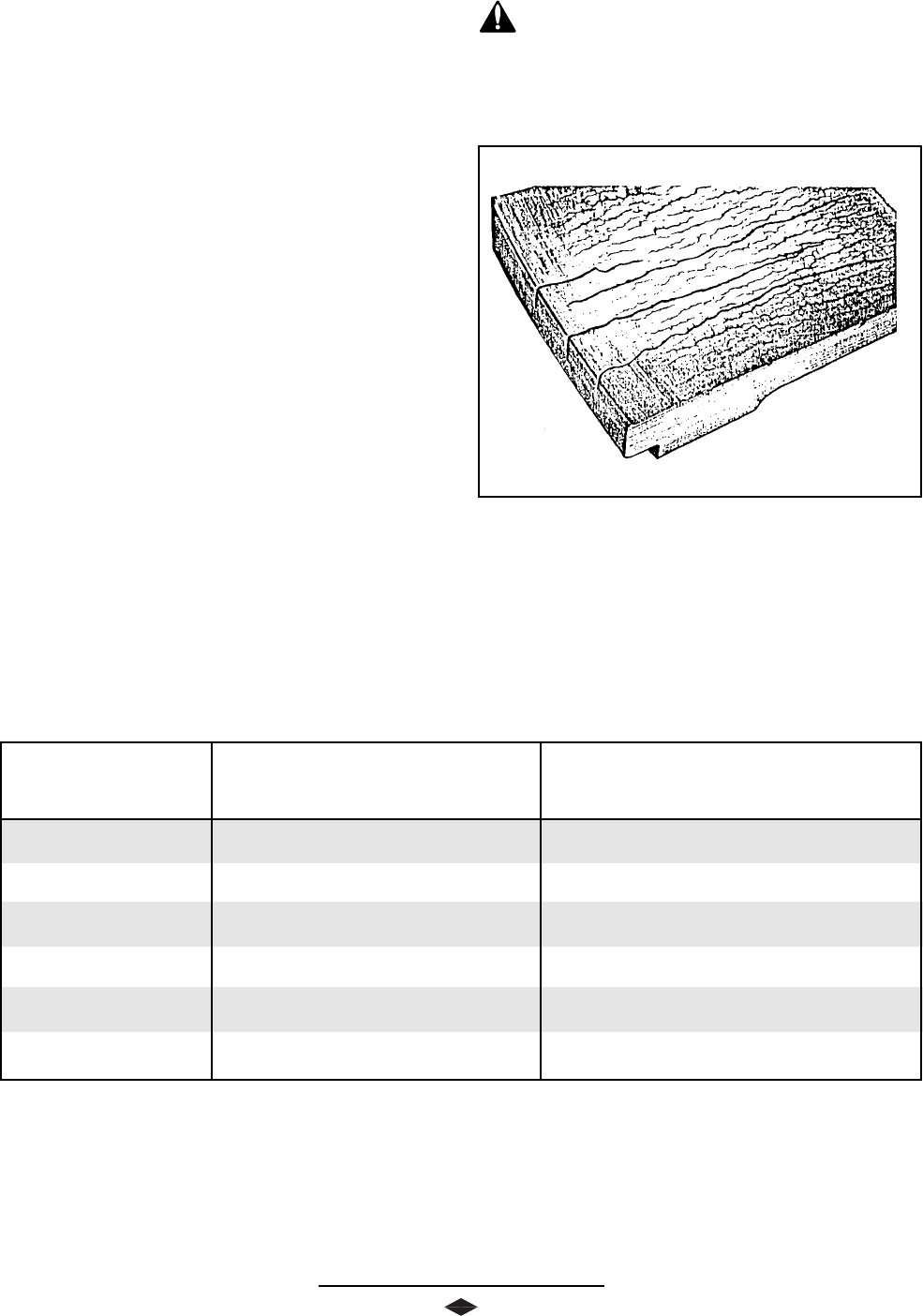
BRAKE DRUMS
Inspect for heat checks, grooves, hot spots, glazing,
cracks, and out of round. Drums which are glazed,
grooved, or have moderate heat checking may be
resurfaced and returned to service. The drum should
not be used if it exceeds the manufacturer’s recom-
mended maximum diameter stamped on the drum.
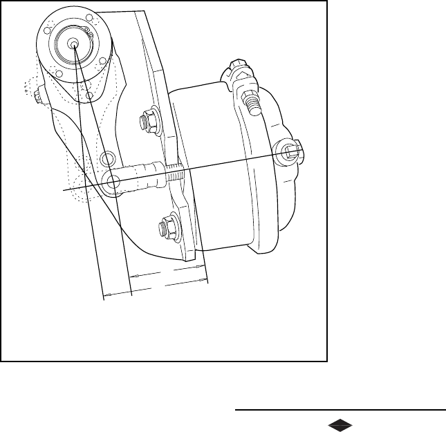
BRAKE ADJUSTMENT
Brakes should be adjusted whenever the air chamber
push rod stroke exceeds the maximum distance accord-
ing to the chart shown in FF
FF
Figurigur
igurigur
igure 2e 2
e 2e 2
e 2. To determine if
brake adjustment is required measure the push rod
stroke with the brakes applied as shown in FF
FF
Figurigur
igurigur
igure 3e 3
e 3e 3
e 3 onon
onon
on
page 1page 1
page 1page 1
page 1
0.0.
0.0.
0.
PREVENTATIVE MAINTENANCE
CA CA
CA CA
CAUTION:UTION:
UTION:UTION:
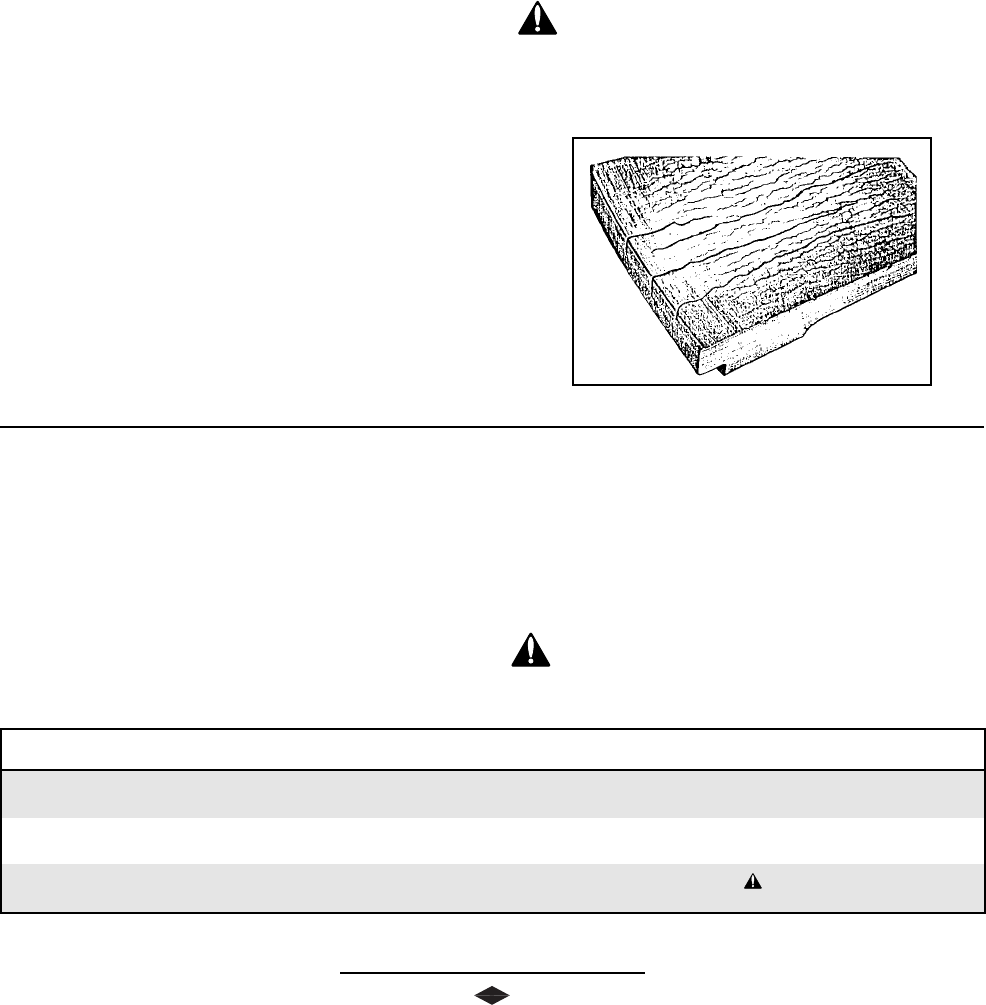
UTION: Drums displaDrums displa
Drums displaDrums displa
Drums displaying heaying hea
ying heaying hea
ying heat checks witht checks with
t checks witht checks with
t checks with
a contina contin
a contina contin
a continuous length of four incheuous length of four inche
uous length of four incheuous length of four inche
uous length of four inches or mors or mor
s or mors or mor
s or more ande and
e ande and
e and
ee
ee
extxt
xtxt
xtends arends ar
ends arends ar
ends around the edge of the drum should beound the edge of the drum should be
ound the edge of the drum should beound the edge of the drum should be
ound the edge of the drum should be
rr
rr
replaced. eplaced.
eplaced. eplaced.
eplaced. See FSee F
See FSee F
See Figurigur
igurigur
igure 1.e 1.
e 1.e 1.
e 1.
FF
FF
Figurigur
igurigur
igure 1e 1
e 1e 1
e 1
FF
FF
Figurigur
igurigur
igure 2e 2
e 2e 2
e 2
Chamber Size
Type
RECOMMENED AIR BRAKE ACTUATOR SERVICE STROKE
Source: The Maintenance Council RP 635
9
10
PREVENTATIVE MAINTENANCE
AA
AA
A
A.A.
A.A.
A. Released Position
B. B.
B. B.
B. Applied Postion
BB
BB
B
MEASURING PUSH ROD STROKE
1.1.
1.1.
1. Measure the distance between the air chamber
mounting face and the center of the clevis pin,
with brakes released.
2.2.
2.2.
2. Make an 70-90 PSI application and hold it.
Measure the distance between the air chamber and
the mounting face and the center of the clevis pin.
3.3.
3.3.
3. Subtract measurement A from measurement B. If
this measurement equals or exceeds the maximum
readjust stroke the brakes need to be adjusted.
See FSee F
See FSee F
See Figurigur
igurigur
igure 3.e 3.
e 3.e 3.
e 3.
4.4.
4.4.
4. If adjustment is required, spin the wheel slowly and
adjust the slack adjuster just enough for wheel to
spin freely. Be sure to adjust brakes equally on
each axle.
5.5.
5.5.
5. Apply and release brakes and observe slack
adjusters. Both slacks on each axle should respond
rapidly and in unison during application and
release.
6.6.
6.6.
6. Drive vehicle at a low speed in a safe area and
check for brake effectiveness prior to putting back
in service.
F F
F F
Figurigur
igurigur
igure 3e 3
e 3e 3
e 3
BRAKE LUBRICTION
Lubricate the camshaft thru the grease fitting on the
camshaft bracket with the chassis lube specified by the
vehicle manufacturer. Lube once every six months or at
every chassis lubrication.
BRAKE RELINE
The life of the brake lining is dependent on many factors
such as the material of the lining, type of operation the
vehicle is used for, geographic terrain, maintenance
practice of the shop, and the driver of the vehicle. If
driving conditions require frequent braking, lining
replacement will be required more often.
FOR RIVET LINING
Reline when thickness of lining is 1/4 " at thinnest
point, or 1/16" above rivet head.
FOR CAST SHOES WITH BOLTED LININGS
Reline when lining is below wear indicator line or
thickness is .31" at the thinnest point or 1/16" above
bolt head.
BRAKE OVERHAUL
As often as necessary to maintain satisfactory brake
performance. When overhauling the brakes, provide equal
service to both the left and right side of an axle.

BRAKE DISASSEMBLY
CAST SHOE & "P" SERIES
1.1.
1.1.
1. Insert sturdy lever between end of shoe and spider.
Pry shoe away from cam until cam rollers can be
removed. Repeat procedure for opposite shoe.
2.2.
2.2.
2. Unhook shoe return spring by pushing shoes
together, allow tension on spring to be reduced.
3.3.
3.3.
3. Discard shoe return spring and replace with new at
time of reassembly.
4.4.
4.4.
4. Remove snap ring from anchor pin and push anchor
pin through.
NONO
NONO
NOTE: TTE: T
TE: TTE: T
TE: Tap lightlap lightl
ap lightlap lightl
ap lightly with bry with br
y with bry with br
y with braa
aa
ass drift if anchor pin willss drift if anchor pin will
ss drift if anchor pin willss drift if anchor pin will
ss drift if anchor pin will
nono
nono
not push out with fingert push out with finger
t push out with fingert push out with finger
t push out with finger.....
5.5.
5.5.
5. Remove brake shoe and place on floor. Repeat
procedure for opposite shoe.
STANDARD, XL, & XLII SERIES
1.1.
1.1.
1. Insert sturdy lever between end of shoe and spider.
Pry shoe away from cam until cam rollers can be
removed. Repeat procedure for opposite shoe.
2.2.
2.2.
2. Unhook shoe return spring by pushing shoes
together, allow tension on spring to be reduced.
3.3.
3.3.
3. Discard shoe return spring and replace with new at
time of reassembly.
4a.4a.
4a.4a.
4a. SS
SS
STT
TT
TANDAND
ANDAND
ANDARD & XLARD & XL
ARD & XLARD & XL
ARD & XL
Remove shoes by rotating the bottom shoe off the
anchor pin to release the tension on the two
retaining springs.
4b.4b.
4b.4b.
4b. XLII SERIESXLII SERIES
XLII SERIESXLII SERIES
XLII SERIES
Remove snap ring from anchor pin and push anchor
pin through.
5.5.
5.5.
5. Remove the two retaining springs and discard.
6.6.
6.6.
6. Remove shoes from spider.
11
CAMSHAFT REMOVAL
1.1.
1.1.
1. Before removing camshaft check to see if cam bushings
need replacement. See F See F
See F See F
See Figurigur
igurigur
igure 4 on Pe 4 on P
e 4 on Pe 4 on P
e 4 on Page 1age 1
age 1age 1
age 1
2.2.
2.2.
2.
2.2.
2.2.
2. Remove spacer from between slack adjuster and cam
shaft bracket.
3.3.
3.3.
3. Grasp camshaft at the camshaft head and pull in the
outward direction to remove.
4.4.
4.4.
4. Clean and inspect camshaft splines and head.
AIR CHAMBER/ CAMSHAFT BRACKET
ASSMEBLY REMOVAL
1.1.
1.1.
1. Remove two nuts and washers that secure brake cham-
ber to camshaft bracket.
2.2.
2.2.
2. Remove brake chamber and temporarily set it aside.
3.3.
3.3.
3. Remove four bracket mounting bolts and lock washers.
4.4.
4.4.
4. Remove bracket assembly from spider.
CA CA
CA CA
CAUTION: UTION:
UTION: UTION:
UTION: Do noDo no
Do noDo no
Do not hammer on slack adjustt hammer on slack adjust
t hammer on slack adjustt hammer on slack adjust
t hammer on slack adjuster ter t
er ter t
er too
oo
o
rr
rr
remoemo
emoemo
emovv
vv
ve. Serious damage te. Serious damage t
e. Serious damage te. Serious damage t
e. Serious damage to the slack adjusto the slack adjust
o the slack adjusto the slack adjust
o the slack adjuster and/er and/
er and/er and/
er and/
or the camshaft splineor the camshaft spline
or the camshaft splineor the camshaft spline
or the camshaft splines mas ma
s mas ma
s may ry r
y ry r
y ree
ee
esult.sult.
sult.sult.
sult.
SLACK ADJUSTER REMOVAL
1.1.
1.1.
1. Disconnect clevis from slack adjuster arm by
removing the clevis pin or pins depending on type
of slack adjuster.
2.2.
2.2.
2. Remove retaining ring and shims from splined end
of camshaft.
3.3.
3.3.
3. Remove slack adjuster from the camshaft.
CA CA
CA CA
CAUTION: UTION:
UTION: UTION:
UTION: Do noDo no
Do noDo no
Do not let le
t let le
t let the air chamber hang bt the air chamber hang b
t the air chamber hang bt the air chamber hang b
t the air chamber hang byy
yy
y
the air linethe air line
the air linethe air line
the air liness
ss
s
AIR CHAMBER BRACKET ASSEMBLY
INSPECTION OF PARTS
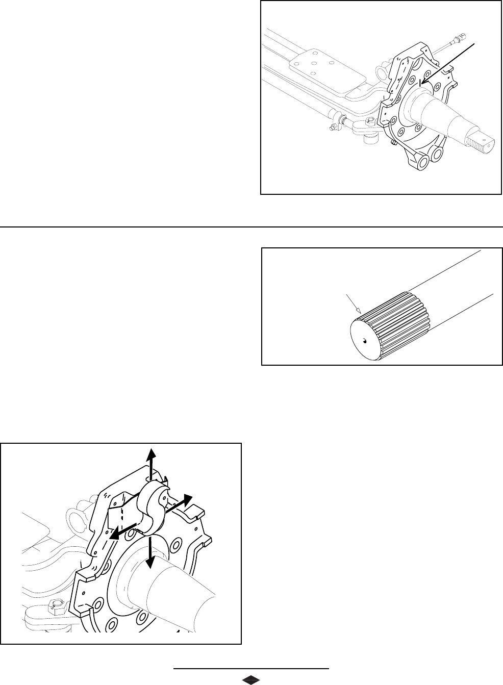
SPIDER REMOVAL
1.1.
1.1.
1. Mark the postion of the spider on the axle (L.H. or
R.H.) and the orientation on the axle flange by
making a reference mark on the spider and flange.
See FSee F
See FSee F
See Figurigur
igurigur
igure 4.e 4.
e 4.e 4.
e 4.
2. 2.
2. 2.
2. Remove the spider to axle mounting bolts.
3. 3.
3. 3.
3. Remove spider.
DUST SHIELD REMOVAL
1.1.
1.1.
1. Mark dust shields (upper left, lower right, etc-
prior to removal.
2.2.
2.2.
2. Detach dust sheild by removing the six cap screws
using a 9/16" socket. Do not remove dust shield
unless there is apparent damage.
BRAKE DISASSEMBLY (CONTINUED)
FF
FF
Figurigur
igurigur
igure 4e 4
e 4e 4
e 4
1.1.
1.1.
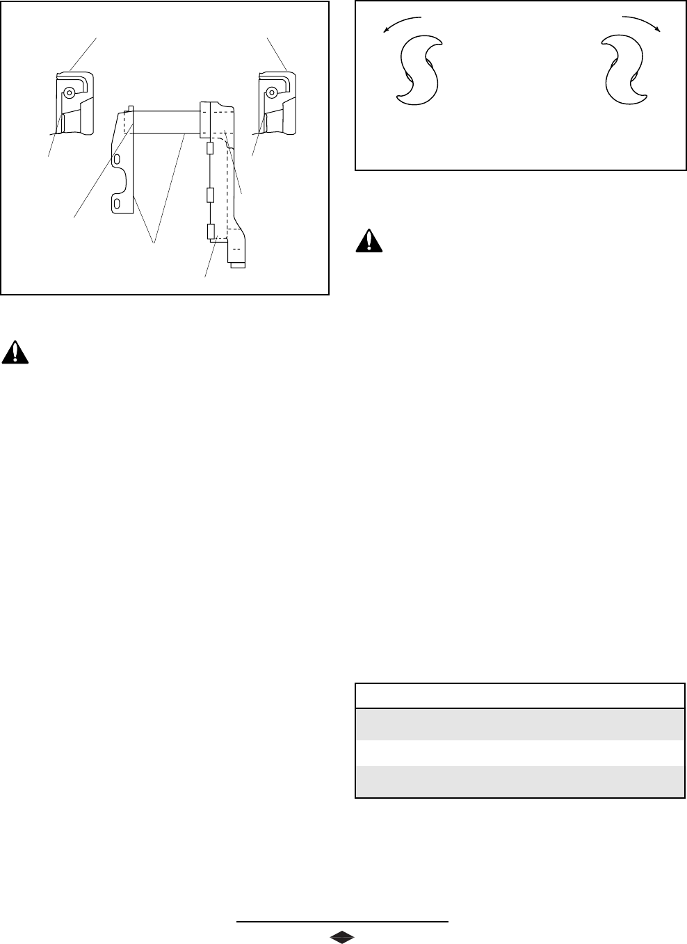
1. Check assembly for bent chamber bracket, broken
welds, cracks, and correct alignment.
2.2.
2.2.
2. Inspect camshaft bushings for signs of wear.
Bearing surfaces should be smooth and free of any
pitting or fractures. Insert camshaft and measure
looseness up and down side to side at both ends
with a dial indicator. If more than .030” movement,
replace bushings and/or camshaft. See FSee F
See FSee F
See Figurigur
igurigur
igure 5.e 5.
e 5.e 5.
e 5.
NONO
NONO
NOTE: If it is deTE: If it is de
TE: If it is deTE: If it is de
TE: If it is dett
tt
termined thaermined tha
ermined thaermined tha
ermined that a bushing rt a bushing r
t a bushing rt a bushing r
t a bushing requirequir
equirequir
equiree
ee
ess
ss
s
rr
rr
replacement, boeplacement, bo
eplacement, boeplacement, bo
eplacement, both camshaft bushings and sealsth camshaft bushings and seals
th camshaft bushings and sealsth camshaft bushings and seals
th camshaft bushings and seals
should be rshould be r
should be rshould be r
should be replaced. All CASeplaced. All CAS
eplaced. All CASeplaced. All CAS
eplaced. All CAST SHOE and P SERIEST SHOE and P SERIES
T SHOE and P SERIEST SHOE and P SERIES
T SHOE and P SERIES
brbr
brbr
brakak
akak
akee
ee
es has ha
s has ha
s havv
vv
ve bre br
e bre br
e bronze cam bushings. The Sonze cam bushings. The S
onze cam bushings. The Sonze cam bushings. The S
onze cam bushings. The STT
TT
TANDAND
ANDAND
ANDARD,ARD,
ARD,ARD,
ARD,
XL, and XLII SERIES brXL, and XLII SERIES br
XL, and XLII SERIES brXL, and XLII SERIES br
XL, and XLII SERIES brakak
akak
akee
ee
es use ns use n
s use ns use n
s use nylon bushings withylon bushings with
ylon bushings withylon bushings with
ylon bushings with
the brthe br
the brthe br
the bronze bushing aonze bushing a
onze bushing aonze bushing a
onze bushing as an ops an op
s an ops an op
s an option.tion.
tion.tion.
tion.
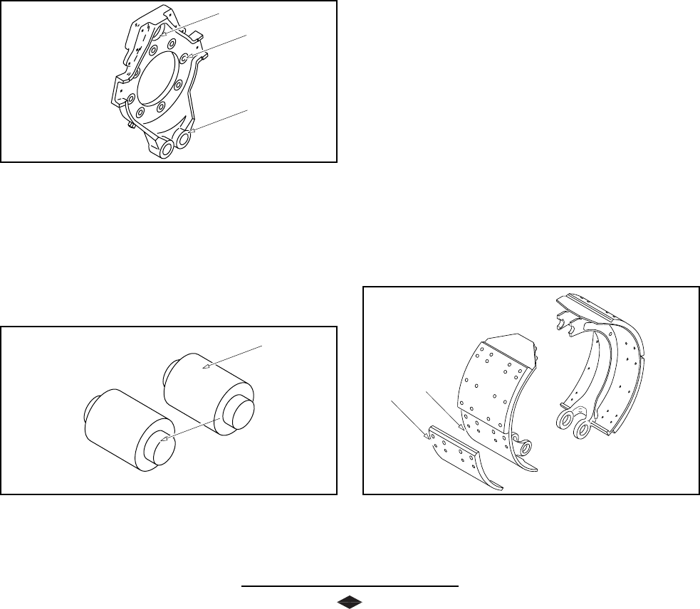
CAMSHAFT
1.1.
1.1.
1. Inspect camshaft spline and body for chips and
excessive deformation. Replace as necessary.
See FSee F
See FSee F
See Figurigur
igurigur
igure 6.e 6.
e 6.e 6.
e 6.
2.2.
2.2.
2. Inspect cam head for cracks, and its roller surfaces
for flat spots, brinneling, or ridges.
NONO
NONO
NOTE: UnTE: Un
TE: UnTE: Un
TE: Unusual wusual w
usual wusual w
usual wear paear pa
ear paear pa
ear patt
tt
ttt
tt
terns which maerns which ma
erns which maerns which ma
erns which may indicay indica
y indicay indica
y indicatt
tt
te ane an
e ane an
e an
outout
outout
out-of-squar-of-squar
-of-squar-of-squar
-of-square condition. Re condition. R
e condition. Re condition. R
e condition. Replace damaged cam-eplace damaged cam-
eplace damaged cam-eplace damaged cam-
eplace damaged cam-
shaftshaft
shaftshaft
shafts.s.
s.s.
s.
FF
FF
Figurigur
igurigur
igure 5e 5
e 5e 5
e 5
FF
FF
Figurigur
igurigur
igure 6e 6
e 6e 6
e 6
12
SHOES AND LINING
STANDARD, XL, XL II AND P SERIES
1.1.
1.1.
1. Check shoes for bent shoe ribs, cracks in shoe
table welds or ribs, and elongated rivet holes.
Replace shoes if any of these conditions exist. SeeSee
SeeSee
See
FF
FF
Figurigur
igurigur
igure 9.e 9.
e 9.e 9.
e 9.
2.2.
2.2.
2. Measure the shoe span by loosely installing the
anchor pin and cam roller in the appropriate ends
of the shoe rib. If the distance from center of
anchor pin to center of cam roller exceeds 12.76
inches replace shoe.
3.3.
3.3.
3. Check linings and replace when any of the following
conditions exist: See page 21 for reline procedure.
A.A.
A.A.
A. Total lining thickness at thinnest point is 1/4"
or less, or 1/16" above the rivets.
B. B.
B. B.
B. Linings are cracked or worn in an unusual or
odd pattern. For example: lining wear tapered
from side to side across the shoe table. Un
usual wear pattern can indicate damage to
foundation brake parts.
C. C.
C. C.
C. Rivet holes are elongated in lining or shoes.
D. D.
D. D.
D. Lining is oil soaked.
E. E.
E. E.
E. Linings can be moved by hand because of loose
rivets.
13
SPIDER
1.1.
1.1.
1. Inspect for cracked or broken surfaces on the
spider at the cam, anchor pins, and mounting bolt
holes. Replace any spider with visible damage. Do
not attempt to weld or repair the spiders. SeeSee
SeeSee
See
FF
FF
Figurigur
igurigur
igure 7e 7
e 7e 7
e 7
.....
XLII, P, & CAST SHOE SERIES
2a2a
2a2a
2a. Check the inside diameter of the anchor pin hole
with bushing in place. Diameter must not exceed
1.282”. Replace bushing if necessary.
STANDARD & XL SERIES
2b.2b.
2b.2b.
2b. The anchor pins are staked into the spider and are
not serviced separately. If the pins are loose or
grooved more than .030 inch, the spider assembly
must be replaced.
ROLLERS AND ANCHOR PINS, BUSHINGS
1.1.
1.1.
1. Inspect rollers and anchor pins for flat spots,
galling, broken or cracked surfaces. Replace as
necessary. See FSee F
See FSee F
See Figurigur
igurigur
igure 8.e 8.
e 8.e 8.
e 8.
INSPECTION OF PARTS
FF
FF
Figurigur
igurigur
igure 7e 7
e 7e 7
e 7
FF
FF
Figurigur
igurigur
igure 8e 8
e 8e 8
e 8 FF
FF
Figurigur
igurigur
igure 9e 9
e 9e 9
e 9
INSPECTION OF PARTS (CONTINUED)
14
FF
FF
Figurigur
igurigur
igure 1e 1
e 1e 1
e 1
00
00
0
TRANSIT BRAKE (CAST SHOE ONLY) DRUM/
LINING CROSS REFERENCE CHART
1.1.
1.1.
1. When installing new drums always use standard
thickness lining. If used drums are rebored care-
fully measure inside diameter (in several places) of
rebored drum.
LINING MAXIMUM THICKNESS (IN) DRUM DIA. (IN) AT RELINE
.867” (Standard Thickness)
.927” (1X Oversize)
.987” (Premium Thickness)
16.500”- New
16.620”
Over 16.620”
CA CA
CA CA
CAUTION:UTION:
UTION:UTION:
UTION: NeNe
NeNe
Nevv
vv
ver shim brer shim br
er shim brer shim br
er shim brakak
akak
ake linings. See pagee linings. See page
e linings. See pagee linings. See page
e linings. See page
22
22
21, R1, R
1, R1, R
1, Reline Preline Pr
eline Preline Pr
eline Procedurocedur
ocedurocedur
ocedure, for more, for mor
e, for more, for mor
e, for more dee de
e dee de
e dett
tt
tail.ail.
ail.ail.
ail.
2.2.
2.2.
2. Refer to the chart below for proper oversized lining
required based on drum measurements.
SHOES AND LINING
CAST SHOE TYPE
1.1.
1.1.
1. Check shoes for cracks and elongated bolt holes.
2.2.
2.2.
2. Measure the shoe span by loosely installing the
anchor pin and cam roller in the appropriate ends
of the shoe rib. If the distance from center of
anchor pin to center of cam roller exceeds 12.76
inches replace shoe.
3.3.
3.3.
3. Check linings, replace when any of the following
conditions exist.
A. Total lining thickness at thinnest point is .31” or
less than 1/16” above screw head. Also, if the
material is worn beyond the wear groove on the
side of the lining.
B.B.
B.B.
B. Linings are cracked or worn in an unusual or
odd pattern. For example: lining wear tapered
from side to side across the shoe table. Un
usual wear pattern can indicate damage to
foundation brake parts.
C.C.
C.C.
C. Screw holes are elongated.
D.D.
D.D.
D. Lining is oil soaked.
E.E.
E.E.
E. Lining can be moved by hand. (loose bolts)
CA CA
CA CA
CAUTION:UTION:
UTION:UTION:
UTION: Drums displaDrums displa
Drums displaDrums displa
Drums displaying heaying hea
ying heaying hea
ying heat checks witht checks with
t checks witht checks with
t checks with
a contina contin
a contina contin
a continuous length of four incheuous length of four inche
uous length of four incheuous length of four inche
uous length of four inches or mors or mor
s or mors or mor
s or more ande and
e ande and
e and
ee
ee
extxt
xtxt
xtend arend ar
end arend ar
end around the edge of the drum should beound the edge of the drum should be
ound the edge of the drum should beound the edge of the drum should be
ound the edge of the drum should be
rr
rr
replaced. eplaced.
eplaced. eplaced.
eplaced. See FSee F
See FSee F
See Figurigur
igurigur
igure 1e 1
e 1e 1
e 1
0.0.
0.0.
0.
BRAKE DRUMS
1.1.
1.1.
1. Inspect drums for cracks, heat checking, glazing,
grooving, severe out-of-round condition or bell
mouthing mm
mm
must noust no
ust noust no
ust not et e
t et e
t exx
xx
xceed .0ceed .0
ceed .0ceed .0
ceed .022
22
25 T5 T
5 T5 T
5 T.I.R. (T.I.R. (T
.I.R. (T.I.R. (T
.I.R. (Too
oo
ott
tt
talal
alal
al
IndicaIndica
IndicaIndica
Indicatt
tt
tor Ror R
or Ror R
or Reading) eading)
eading) eading)
eading) Replace any drums that are
cracked. The drum should not be used if it exceeds
the manufacturer’s recommended maximum
diameter stamped on the drum.
2.2.
2.2.
2. Measure the drum I.D. to be sure the maximum limit
allowed (stamped on drum) has not been exceeded
due to wear or machining.
CAUTION: Maximum discard
diameter is 16.750”
CA CA
CA CA
CAUTION:UTION:
UTION:UTION:
UTION: Left Hand and Right Hand does
not
establish which side of the vehicle the cam goes on. Left
and right are used to identify the two different types of
cams only.
2.2.
2.2.
2. Place steel spacer plate over splined end and slide
next to cam head. (See br(See br
(See br(See br
(See brakak
akak
ake componente component
e componente component
e components ons on
s ons on
s on
pagepage
pagepage
pages 3-6)s 3-6)
s 3-6)s 3-6)
s 3-6)
3.3.
3.3.
3. Coat bushing, seals, journals and camshaft spline
with light film of chassis lube.
IMPORIMPOR
IMPORIMPOR
IMPORTT
TT
TANTANT
ANTANT
ANT: Do no: Do no
: Do no: Do no
: Do not coat coa
t coat coa
t coat "S" cam head.t "S" cam head.
t "S" cam head.t "S" cam head.
t "S" cam head.
4.4.
4.4.
4. Carefully install camshaft through the chamber
bracket tube, from spider end. Cam must rotate
freely when turned by hand.
IMPORIMPOR
IMPORIMPOR
IMPORTT
TT
TANTANT
ANTANT
ANT: Be car: Be car
: Be car: Be car
: Be careful noeful no
eful noeful no
eful not tt t
t tt t
t to damage the gro damage the gr
o damage the gro damage the gr
o damage the greaea
eaea
easese
sese
se
seals.seals.
seals.seals.
seals.
SPICER S-CAM BRAKE RETURN SPRINGS
Br Br
Br Br
Brakak
akak
ake Seriee Serie
e Seriee Serie
e Seriess
ss
sRR
RR
Ree
ee
eturn Springs P/N & Colorturn Springs P/N & Color
turn Springs P/N & Colorturn Springs P/N & Color
turn Springs P/N & Color
Standard 165WJ110 Dark Blue
XL & Cast Shoe 165WJ115 White
XLII 165WJ129 Light Blue
BRAKE ASSEMBLY
CA CA
CA CA
CAUTION:UTION:
UTION:UTION:
UTION: The lip of the grThe lip of the gr
The lip of the grThe lip of the gr
The lip of the greaea
eaea
ease seals mse seals m
se seals mse seals m
se seals must beust be
ust beust be
ust be
instinst
instinst
installed corralled corr
alled corralled corr
alled correctlectl
ectlectl
ectly ty t
y ty t
y to pro pr
o pro pr
o pree
ee
evv
vv
vent posssible damage. Theent posssible damage. The
ent posssible damage. Theent posssible damage. The
ent posssible damage. The
lip of the seal thalip of the seal tha
lip of the seal thalip of the seal tha
lip of the seal that is instt is inst
t is instt is inst
t is installed in the spider end malled in the spider end m
alled in the spider end malled in the spider end m
alled in the spider end mustust
ustust
ust
entent
entent
enter the opening firer the opening fir
er the opening firer the opening fir
er the opening first. The lip of the seal thast. The lip of the seal tha
st. The lip of the seal thast. The lip of the seal tha
st. The lip of the seal that ist is
t ist is
t is
instinst
instinst
installed in the oppositalled in the opposit
alled in the oppositalled in the opposit
alled in the opposite end of the cam tube me end of the cam tube m
e end of the cam tube me end of the cam tube m
e end of the cam tube mustust
ustust
ust
entent
entent
enter laer la
er laer la
er last. st.
st. st.
st. See FSee F
See FSee F
See Figurigur
igurigur
igure 1e 1
e 1e 1
e 1
11
11
1. Inst. Inst
. Inst. Inst
. Install the chamberall the chamber
all the chamberall the chamber
all the chamber
brbr
brbr
brackack
ackack
ackee
ee
et and the cam tube at and the cam tube a
t and the cam tube at and the cam tube a
t and the cam tube assemblssembl
ssemblssembl
ssembly onty ont
y onty ont
y onto the spidero the spider
o the spidero the spider
o the spider
using four cap scrusing four cap scr
using four cap scrusing four cap scr
using four cap scree
ee
eww
ww
ws and lockws and lockw
s and lockws and lockw
s and lockwaa
aa
ashersher
shersher
shers. Ts. T
s. Ts. T
s. Toror
oror
orque tque t
que tque t
que too
oo
o
77
77
70-80-8
0-80-8
0-80 Lb-Ft.0 Lb-Ft.
0 Lb-Ft.0 Lb-Ft.
0 Lb-Ft.
If removed, reinstall the dust shields. Tighten the six cap
screws and lockwashers to 20-28 Lb-Ft of torque.
SPIDER
1.1.
1.1.
1. Use a wire brush to remove heavy contamination
from the spider mounting flange, knuckle, spider,
brake drum exterior, and chamber mounting
bracket.
2.2.
2.2.
2. Install the spider and chamber bracket assembly
onto the axle flange. Be sure spider is properly
oriented, as noted during disassembly. Tighten
mounting fastener to manufacturer's specifications.
CAMSHAFT
1.1.
1.1.
1. Prior to reassembly, verify the part number is
correct there are L.H. and R.H. camshafts and they
can not be interchanged. See FSee F
See FSee F
See Figurigur
igurigur
igure 1e 1
e 1e 1
e 1
2.2.
2.2.
2.
Seal Installation
CHAMBER BRACKET ASSEMBLY
15
Lip SealLip Seal
Lip SealLip Seal
Lip Seal
SpiderSpider
SpiderSpider
Spider
AA
AA
Actuactua
ctuactua
ctuatt
tt
tor Bror Br
or Bror Br
or Brackack
ackack
ackee
ee
ett
tt
t
and Cam Tand Cam T
and Cam Tand Cam T
and Cam Tubeube
ubeube
ube
Slack ASlack A
Slack ASlack A
Slack Adjustdjust
djustdjust
djuster Ender End
er Ender End
er End
NONO
NONO
NOTE: BoTE: Bo
TE: BoTE: Bo
TE: Both lip seals point the sameth lip seals point the same
th lip seals point the sameth lip seals point the same
th lip seals point the same
dirdir
dirdir
direction, lip tection, lip t
ection, lip tection, lip t
ection, lip too
oo
oww
ww
warar
arar
ard the slack adjustd the slack adjust
d the slack adjustd the slack adjust
d the slack adjusterer
erer
er
Lip SealLip Seal
Lip SealLip Seal
Lip Seal
End CamEnd Cam
End CamEnd Cam
End Cam
FF
FF
Figurigur
igurigur
igure 1e 1
e 1e 1
e 1
11
11
1
Right Hand CamRight Hand Cam
Right Hand CamRight Hand Cam
Right Hand Cam
Left Hand CamLeft Hand Cam
Left Hand CamLeft Hand Cam
Left Hand Cam
FF
FF
Figurigur
igurigur
igure 1e 1
e 1e 1
e 1
22
22
2
BRAKE SHOE ASSEMBLY
STANDARD, XL & XL II SERIES
1.1.
1.1.
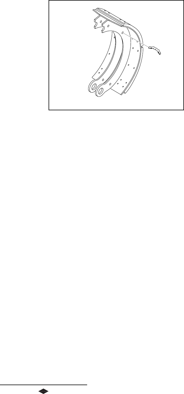
1. Install new return spring pins:
A. StA. St
A. StA. St
A. Standarandar
andarandar
andard Seried Serie
d Seried Serie
d Seriess
ss
s- Wireform pin installed in shoe
ribs with mallet.
B. XL SerieB. XL Serie
B. XL SerieB. XL Serie
B. XL Seriess
ss
s- 2 piece kit assembly consisting of
inner pin and outer pin.
2.2.
2.2.
2. Apply a thin film of Lubriplate 630-A grease or its
equivalent to the anchor pin.
3.3.
3.3.
3. Install new brake retaining springs in the anchor
end of shoes. Place the top shoe onto the spider
by engaging the open slots on the end with the
retaining springs onto the anchor pin. Place
opposite end of the shoe against the S-cam. Swing
the lower shoe, with springs attached, back until
slots in the shoe engage the anchor pin. Rotate the
shoe toward the S-cam. Lower shoe may require
support while completing assembly.
4a.4a.
4a.4a.
4a. StSt
StSt
Standarandar
andarandar
andard Seried Serie
d Seried Serie
d Seriess
ss
s- Utilize leg on shoe return spring
to aid in assembly. Place the one hook of the brake
shoe return spring onto the return spring pin.
Hold shoes firmly against the S-cam. Push the
other hook of the brake shoe return spring over the
opposite return spring pin until it snaps in place.
4b.4b.
4b.4b.
4b. XL/XL II SerieXL/XL II Serie
XL/XL II SerieXL/XL II Serie
XL/XL II Seriess
ss
s- place the one hook of the brake
shoe return spring onto the return spring pin
located between the shoe ribs. Hold both shoes
against the S-cam head. Push the other hook of
the return spring over the opposite shoe spring pin
until it snaps in place.
5.5.
5.5.
5. Apply a thin film of Lubriplate 630-A grease or its
equivalent to the cam roller journal, and the roller
side only. Do not put grease on the end of the
roller which contacts the cam head.
6.6.
6.6.
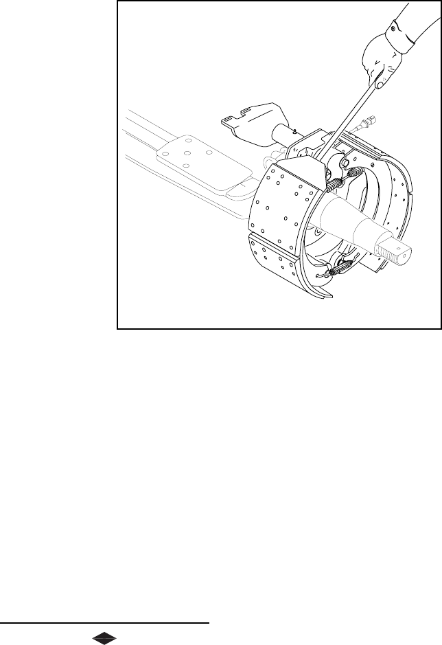
6. Insert sturdy lever between end of shoe and the
return spring pin. See FSee F
See FSee F
See Figurigur
igurigur
igure 1e 1
e 1e 1
e 1
33
33
3. Pry away from
the cam until cam rollers can be installed between
BRAKE ASSEMBLY (CONTINUED)
the S-cam and the slots in the end of the brake
shoe. Make sure the cam rollers are in the lowest
position on the cam. Repeat procedure for oppo-
site side.
CAST SHOE SERIES
1.1.
1.1.
1. Apply a thin film of Lubriplate 630-A grease or its
equivalent to the anchor pin.
2.2.
2.2.
2. Place snap ring on anchor pin end with grease
fitting. Place thin spacer onto anchor pin.
3.3.
3.3.
3. Align anchor pin end of cast shoe with spider bore.
4.4.
4.4.
4. Install anchor pin through backside of shoe and
spider. Repeat procedure for opposite shoe.
5.5.
5.5.
5. Place thin spacer onto opposite side of anchor pins
and install snap rings.
6.6.
6.6.
6. Hook shoe return spring by pushing shoes to-
gether. The cast shoe does not have a separate
return spring pin. The spring hook-up feature is
designed into the shoe casting.
77
77
7..... Insert sturdy lever between end of shoe and spider.
Pry shoe away from cam until cam rollers can be
installed. Repeat procedure for opposite side. SeeSee
SeeSee
See
FF
FF
Figurigur
igurigur
igure 1e 1
e 1e 1
e 1
3.3.
3.3.
3.
16
FF
FF
Figurigur
igurigur
igure 1e 1
e 1e 1
e 1
33
33
3
BRAKE ASSEMBLY (CONTINUED)
17
FF
FF
Figurigur
igurigur
igure 1e 1
e 1e 1
e 1
44
44
4
“P” SERIES
11
11
1. Install new return spring pins. See FSee F
See FSee F
See Figurigur
igurigur
igure 1e 1
e 1e 1
e 1
4.4.
4.4.
4.
2.2.
2.2.
2. Align lower end of fabricated shoe with spider bore.
3.3.
3.3.
3. Place snap ring on anchor pin end with grease
fitting. Place thin spacer onto anchor pin.
4.4.
4.4.
4. Install anchor pin through backside of shoe and
spider.
5.5.
5.5.
5. Apply a thin film of Lubriplate 630-A grease or its
equivalent to the anchor pin.
6.6.
6.6.
6. Place thin spacer onto opposite side of anchor pin
and install snap ring.
77
77
7..... Hook shoe return spring by pushing shoes to-
gether.
8.8.
8.8.
8. Insert sturdy lever between end of shoe and spider.
Pry shoe away from cam until cam rollers can be
installed. Repeat procedure for opposite side.
SLACK ADJUSTER ASSEMBLY
1.1.
1.1.
1. Reinstall thick camshaft flatwasher.
2.2.
2.2.
2. Install new slack adjuster, shims, and a new snap
ring (In that sequence) into the splined end of the
camshaft.
3.3.
3.3.
3. Adjust camshaft end play of the camshaft to
between .005" and .045" by using the appropriate
number of shims. Make sure the snap ring is seated
into the groove at the end of the splined camshaft.
BRAKE LUBRICATION
1.1.
1.1.
1. Lubricate the camshaft bushings by filling the
camshaft tube with lube through the zerk fitting
provided. Fill until grease is forced out in the area
of the slack adjuster. Grease should not appear at
the cam head end. If it does, the seal has not been
properly installed, or the old seals should be
replaced.
2.2.
2.2.
2. Reinstall brake drums and wheels. Torque and
adjust wheel bearings to manufacturer’s specifica-
tions.
NONO
NONO
NOTE: Due tTE: Due t
TE: Due tTE: Due t
TE: Due to the mano the man
o the mano the man
o the many combinay combina
y combinay combina
y combinations of slacktions of slack
tions of slacktions of slack
tions of slack
adjustadjust
adjustadjust
adjusterer
erer
ers and brs and br
s and brs and br
s and brakak
akak
ake chambere chamber
e chambere chamber
e chambers, follos, follo
s, follos, follo
s, follow vw v
w vw v
w vehicleehicle
ehicleehicle
ehicle
manman
manman
manufacturufactur
ufacturufactur
ufacturer’er’
er’er’
er’s specificas specifica
s specificas specifica
s specifications and prtions and pr
tions and prtions and pr
tions and procedurocedur
ocedurocedur
oceduree
ee
es fors for
s fors for
s for
aa
aa
assemblssembl
ssemblssembl
ssembly and final adjustment.y and final adjustment.
y and final adjustment.y and final adjustment.
y and final adjustment.
3.3.
3.3.
3. Spin the wheel slowly and adjust the slack adjuster
until wheel will no longer turn. Back off slack
adjuster just enough for wheel to spin freely. Be
sure to adjust brakes equally on each axle.
4.4.
4.4.
4. Apply the release brakes and observe slack adjust-
ers. Both slacks on each axle should respond
rapidly and in unison during application and
release.
5.5.
5.5.
5. Drive vehicle at a low speed in a safe area and
check for brake effectiveness prior to putting back
in service.

4.4.
4.4.
4. Grabbing or pulling. A.A.
A.A.
A. Grease, oil, or dirt on linings.
B.B.
B.B.
B. Glazed linings.
C.C.
C.C.
C. Brake linings not a balanced set,
different friction codes, or lining brand.
D.D.
D.D.
D. Loose or broken linings.
E.E.
E.E.
E. Brake drum out-of-round.
FF
FF
F..... Defective brake drum.
G.G.
G.G.
G. Clevis pin or camshaft binding at one
or more wheels.
H.H.
H.H.
H. Defective slack adjuster.
I.I.
I.I.
I. Uneven brake adjustment (side to side).
J.J.
J.J.
J. Broken or bent parts.
K.K.
K.K.
K. Loose spider or drum mounting bolts.
L.L.
L.L.
L. Different air chamber size or slack
adjuster length (side to side).
A.A.
A.A.
A. Replace lining.
B.B.
B.B.
B. Deglaze lining or replace.
C.C.
C.C.
C. Replace linings.
D.D.
D.D.
D. Replace linings.
E.E.
E.E.
E. Turn, per manufacturer's specifications.
FF
FF
F..... Replace part.
G.G.
G.G.
G. Clean and lubricate.
H.H.
H.H.
H. Replace part.
I.I.
I.I.
I. Adjust brakes.
J.J.
J.J.
J. Replace part.
K.K.
K.K.
K. Inspect and replace as necessary.
L.L.
L.L.
L. Use same size and type both ends of
the axle.
18
FOUNDATION BRAKE TROUBLESHOOTING CHART
1.1.
1.1.
1. Degraded brake
performance.
SYMPTOM CAUSE REMEDY
A.A.
A.A.
A. Too much push rod free travel.
B.B.
B.B.
B. Severely glazed or worn out linings.
C.C.
C.C.
C. Grease or oil on linings.
D.D.
D.D.
D. Worn, seared, heat checked, cracked
drums.
E.E.
E.E.
E. Push rod length too long.
FF
FF
F..... Air chamber in wrong position.
G.G.
G.G.
G. Broken or bent parts.
H.H.
H.H.
H. Flat spots on cam or rollers.
2.2.
2.2.
2. Slow brake
application.
A.A.
A.A.
A. Adjust brake.
B.B.
B.B.
B. Deglaze linings or replace.
C.C.
C.C.
C. Replace linings.
D.D.
D.D.
D. Replace part.
E.E.
E.E.
E. Adjust clevice, shorten push rod length
FF
FF
F..... Reposition.
G.G.
G.G.
G. Replace part.
H.H.
H.H.
H. Replace flat-spotted parts.
A.A.
A.A.
A. Cam shaft bushings binding. A.A.
A.A.
A. Clean and lubricate. Check for seal
leakage.
3.3.
3.3.
3. Slow brake release. A.A.
A.A.
A. Binding cam shaft and bushing.
B.B.
B.B.
B. Weak or broken shoe return
spring.
C.C.
C.C.
C. Flat spotted cam or rollers.
A.A.
A.A.
A. Clean and lubricate.
B.B.
B.B.
B. Replace part.
C.C.
C.C.
C. Replace flat-spotted parts.

19
5.5.
5.5.
5. Wear on edge of
lining. A.A.
A.A.
A. Wrong width lining.
B.B.
B.B.
B. Holes improperly drilled in lining.
C.C.
C.C.
C. Wrong drum, or improperly machined.
D.D.
D.D.
D. Loose wheel bearing
E.E.
E.E.
E. Improper wheel bearing or cone.
FF
FF
F..... Bent brake shoe.
G.G.
G.G.
G. Bent brake spider.
H.H.
H.H.
H. Worn axle spindle.
A.A.
A.A.
A. Replace linings.
B.B.
B.B.
B. Replace linings.
C.C.
C.C.
C. Replace or turn I.D.
D.D.
D.D.
D. Correct as required.
E.E.
E.E.
E. Correct as required.
FF
FF
F..... Replace part.
G.G.
G.G.
G. Replace part.
H.H.
H.H.
H. Correct as required.
4.4.
4.4.
4. Unequal wear side
to side brakes,
same axle.
A.A.
A.A.
A. Replace linings.
B.B.
B.B.
B. Clean and lubricate.
C.C.
C.C.
C. Replace or turn I.D.
D.D.
D.D.
D. Correct as required.
E.E.
E.E.
E. Reline both brakes together.
A.A.
A.A.
A. Mismatched lining friction codes.
B.B.
B.B.
B. Seized or binding camshaft.
C.C.
C.C.
C. Brake drum surface
in poor condition.
D.D.
D.D.
D. Loose wheel bearing.
E.E.
E.E.
E. Relining one brake.
6.6.
6.6.
6. Glazed linings
(hard & shiny).
A.A.
A.A.
A. Overheating, due to unbalanced
braking system.
B.B.
B.B.
B. Wrong type linings for service
involved.
A.A.
A.A.
A. Correct as required.
B.B.
B.B.
B. Replace linings.
2.2.
2.2.
2. Linings tapered
across width.
A.A.
A.A.
A. Replace parts.
B.B.
B.B.
B. Replace parts.
C.C.
C.C.
C. Replace part.
D.D.
D.D.
D. Correct as required.
A.A.
A.A.
A. Bell-mouth drum.
B.B.
B.B.
B. Bent brake shoe.
C.C.
C.C.
C. Bent brake spider.
D.D.
D.D.
D. Loose wheel bearings.
A.A.
A.A.
A. Bell-mouth drum.
B.B.
B.B.
B. Bent brake spider.
C.C.
C.C.
C. Bent or stretched brake shoe.
D.D.
D.D.
D. Undersize linings.
E.E.
E.E.
E. Loose wheel bearing.
FF
FF
F..... Improper lining grind.
A.A.
A.A.
A. Replace part.
B.B.
B.B.
B. Replace part.
C.C.
C.C.
C. Replace part.
D.D.
D.D.
D. Replace linings.
E.E.
E.E.
E. Correct as required.
FF
FF
F..... Regrind linings to drum
radius minus .015"
3.3.
3.3.
3. Unequal wear on
same brake.
A.A.
A.A.
A. Replace linings.
B.B.
B.B.
B. Replace parts.
C.C.
C.C.
C. Replace flat-spotted parts.
D.D.
D.D.
D. Correct as required.
E.E.
E.E.
E. Replace part.
A.A.
A.A.
A. Mismatched lining friction codes.
B.B.
B.B.
B. Stretched shoe.
C.C.
C.C.
C. Flat spots on cam or roller.
D.D.
D.D.
D. Worn anchor pin.
E.E.
E.E.
E. Worn camshaft or bushings.
1.1.
1.1.
1. Poor lining to drum
contact.
BRAKE SHOE & LINING TROUBLESHOOTING CHART
SYMPTOM CAUSE REMEDY
20
SYMPTOM CAUSE REMEDY
BRAKE DRUM TROUBLESHOOTING CHART
A.A.
A.A.
A. Turn, per manufacturer’s specifications.
B.B.
B.B.
B. Inspect wheel and drum and replace
defective part.
C.C.
C.C.
C. Correct as required.
D.D.
D.D.
D. Replace linings.
E.E.
E.E.
E. Consult vehicle manufacturer.
FF
FF
F..... Check proper brake balance.
G.G.
G.G.
G. Correct as required.
H.H.
H.H.
H. Replace part.
A.A.
A.A.
A. Out round brake drum.
B.B.
B.B.
B. Eccentric mounting of drum.
C.C.
C.C.
C. Loose wheel bearing.
D.D.
D.D.
D. Glazed linings.
E.E.
E.E.
E. Improper friction materials for duty
cycle of vehicle.
FF
FF
F..... Overworked brake.
G.G.
G.G.
G. Driver abuse.
H.H.
H.H.
H. Wrong drum, too light.
2.2.
2.2.
2. Excessive scoring
of drum. A.A.
A.A.
A. Replace linings.
B.B.
B.B.
B. Clean, remove dirt and debris.
C.C.
C.C.
C. Check hardness on flange.
D.D.
D.D.
D. Replace lining.
E.E.
E.E.
E. Turn per manufacturer’s specifications.
FF
FF
F..... Blow out debris.
A.A.
A.A.
A. Defective brake lining.
B.B.
B.B.
B. Abrasive material between lining and
drum.
C.C.
C.C.
C. Soft drum.
D.D.
D.D.
D. Excessive lining wear, rivets contact
ing drum.
E.E.
E.E.
E. Drum not turned at last reline.
FF
FF
F..... Build up of abrasives in rivet holes.
A.A.
A.A.
A. Re-rivet.
B.B.
B.B.
B. Re-rivet.
C.C.
C.C.
C. Replace part.
D.D.
D.D.
D. Replace linings.
E.E.
E.E.
E. Clean, remove rust and paint shoe.
A.A.
A.A.
A. Improper size rivets (too long, too
short, improper diameter).
B.B.
B.B.
B. Improper crimping of rivet.
C.C.
C.C.
C. Enlarged rivet holes in shoe.
D.D.
D.D.
D. Incorrect lining hole size or counter
bore depth.
E.E.
E.E.
E. Rust build up on shoe table.
8.8.
8.8.
8. Loose lining.
A.A.
A.A.
A. Replace part.
B.B.
B.B.
B. Replace lining.
C.C.
C.C.
C. Clean, remove dirt and debris.
D.D.
D.D.
D. Replace linings.
A.A.
A.A.
A. Wrong type rivets.
B.B.
B.B.
B. Rivets not properly crimped.
C.C.
C.C.
C. Dirt or rust on shoe table.
D.D.
D.D.
D. Wrong size lining counter bore.
9.9.
9.9.
9. Cracked lining at
rivet holes.
A.A.
A.A.
A. Loose rivets.
11
11
10.0.
0.0.
0. Elongated rivet
holes.
A.A.
A.A.
A. Replace shoe and lining.
BRAKE SHOE AND LINING TROUBLESHOOTING CHART
1.1.
1.1.
1. Brake drum heat
checked.
A.A.
A.A.
A. Scored or worn drum, not
machined at reline.
B.B.
B.B.
B. Abrasive material between
lining and drum.
A.A.
A.A.
A. Replace or re-machine.
B.B.
B.B.
B. Clean, remove dirt and debris.
77
77
7..... Scored or grooved
linings and drum.
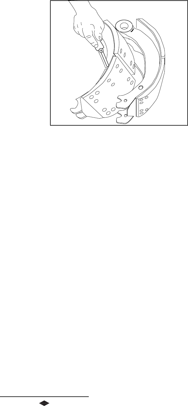
21
RELINE PROCEDURE
The installation should be checked by attempting to
insert a .006" feeler gage between the lining and shoe
table. It should not be possible to insert the feeler gage
anywhere along the edge. See F See F
See F See F
See Figurigur
igurigur
igure 1e 1
e 1e 1
e 1
6.6.
6.6.
6. The only
exception is at each end and beyond the last row of
rivets/bolts. A slightly larger clearance may exist in
these areas.
Riveting Application
Some brake failures result from the use of rivets which
are too short, too long, or the wrong diameter. Incor-
rect setting of the riveting machine may induce other
types of failures.
The solid portion of the rivet should end just at the
inner surface of the shoe. The hollow portion of the
rivet should extend past the inner surface of the shoe.
The proper size rivet must be used to completely fill the
hole.
USE ONLUSE ONL
USE ONLUSE ONL
USE ONLY 1Y 1
Y 1Y 1
Y 1
0-80-8
0-80-8
0-8
1/2 1/2
1/2 1/2
1/2
RIVETSRIVETS
RIVETSRIVETS
RIVETS
Brass plated steel rivets are recommened. The riveting
machine must be adjusted so that the roll of the rivet is
complete, but the rivet should not split. Always use a
roll set, never a star set, when riveting brake linings. A
star set does not compress the rivet and expand it to fill
the hole. Consequently, the lining may work loose in
service.
Bolts/Rivets Removal
When removing bolts/rivets from the brake shoes, be
careful to avoid doing any damage to the holes in the
shoe. Do not use a chisel to shear them off. The force
will elongate the bolt/rivet holes. Neglecting any
elongated holes may result in a loose fitting installation.
If holes are burred, they should be filed down flush with
the shoe table.
Cleaning the Shoe
Rust often developes on the surface of the shoe table
under the brake lining or blocks. During every reline job,
shoe tables should be cleaned thoroughly. The best
procedure is to steam clean the entire shoe or put it into
a degreaser.
After cleaning the shoe, the shoe should be scraped
clean of rust and scale. Any burrs or nicks should be
filed smooth. At the same time, the entire shoe should
be examined to see if it is worn or bent.
Shoe Inspection
The shoe should be either reconditioned or discarded.
It is also necessary to check for flat spots on the shoe
that can be caused by cleaning away the rust from the
area that was under the block previously. This can cause
a mismatch of shoe and lining arcs. After the shoe is
cleaned and inspected, it should be given a coating of
rust preventative paint. Treatment of a new, unpainted
shoe is also suggested to prevent the initial rusting
problem.
Lining Installation
IMPORIMPOR
IMPORIMPOR
IMPORTT
TT
TANTANT
ANTANT
ANT: Ne: Ne
: Ne: Ne
: Nevv
vv
ver shim the brer shim the br
er shim the brer shim the br
er shim the brakak
akak
ake linings.e linings.
e linings.e linings.
e linings. Brake
noise may result because of cracked and/or loose lining
since a tight installation is not possible with shims. The
inside surface of the correct arc to match the shoe table,
and the rivet/bolt holes in the linings will only line up
with holes in the shoes when they are in direct contact.
Prior to riveting/bolting be sure the holes in the lining
blocks and the shoes are exactly matched.
The sequence of riveting/bolting should be such that
the center of the block is attached first and then the
ends. See page 2 See page 2
See page 2 See page 2
See page 22 for bolting sequence.2 for bolting sequence.
2 for bolting sequence.2 for bolting sequence.
2 for bolting sequence.
FF
FF
Figurigur
igurigur
igure 1e 1
e 1e 1
e 1
66
66
6
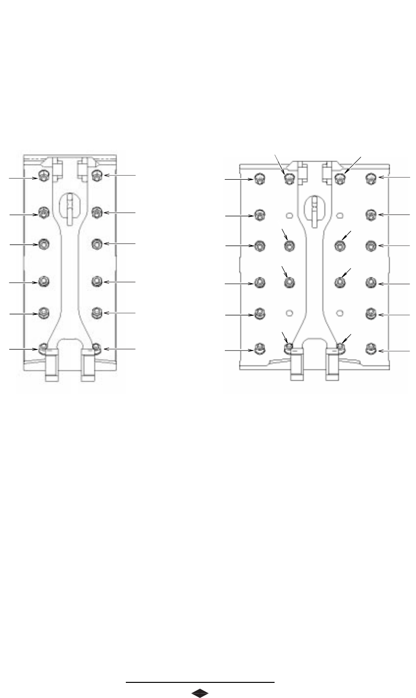
RELINE PROCEDURE
1
3
5
9
7
11
2
6
4
12
8
10
1
7
10
2
9
8
5
6
3
19
12
18
16
14
20
11
4
13
15
17
Bolting Application
Use 3/8 inch diameter copper alloy bolts.
Torque bolts to 15-17 Lb-Ft (20-23 N-m)
Follow the sequence below for the bolt application only.
16.5 x 6 inch 16.5 x 10 inch
22
BRSM-0890
05/04 PDF
Printed in USA
The Roadranger® System is an unbeatable combination of the best
products from Eaton and Dana -- partnering to provide you the most
advanced, most trouble-free drivetrain in the industry. And it's
backed by the Roadrangers -- the most experienced, most expert,
most accessible drivetrain consultants in the business. Visit our web
site at www.roadranger.com. For spec'ing or service assistance,
call 1-800-826-HELP (4357) 24 hours a day, 7 days a week,
(Mexico: 001-800-826-HELP (4357)) for more time on the road.
Copyright Eaton and Dana Corporation,
2002. EATON AND DANA CORPORATION
hereby grants its customers, vendors, or
distributors permission to freely copy,
reproduce and/or distribute this document
in printed format. THIS INFORMATION IS
NOT INTENDED FOR SALE OR RE-
SALE, AND THIS NOTICE MUST REMAIN
ON ALL COPIES.
