Bendix Sd 13 4986 Users Manual
2015-04-02
: Bendix Bendix-Sd-13-4986-Users-Manual-682629 bendix-sd-13-4986-users-manual-682629 bendix pdf
Open the PDF directly: View PDF ![]() .
.
Page Count: 64
1
ESP
®
is a registered trademark of DaimlerChrysler and is used by BCVS under license.
®
SD-13-4986
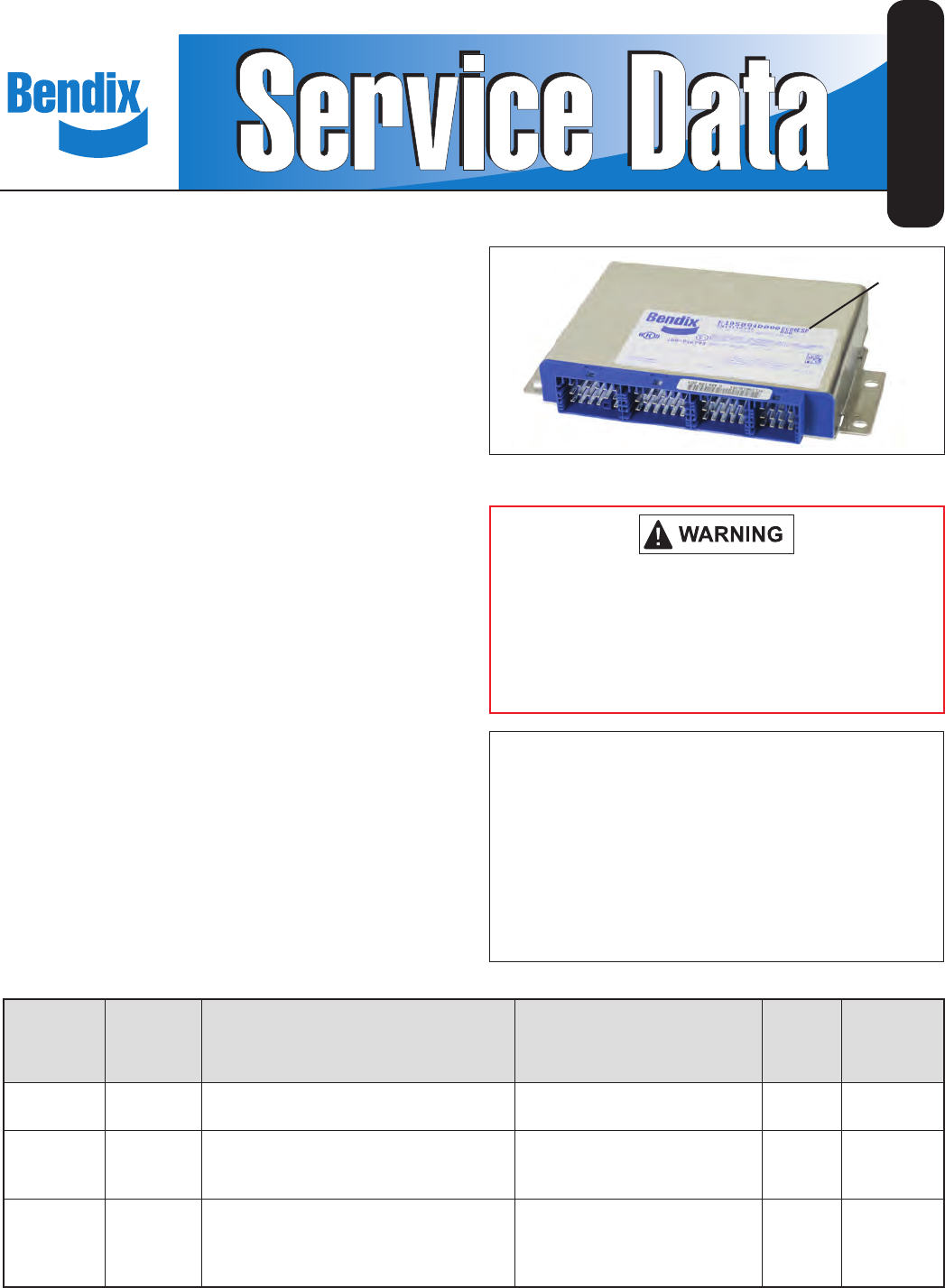
The Bendix® ESP® EC-80™ Controller
INTRODUCTION
The Bendix® ESP® EC‑80™ Electronic Control Unit (ECU)
is a member of a family of three Bendix®‑brand electronic
Antilock Braking System (ABS) devices used to help
improve the braking characteristics of air‑braked heavy‑
and medium‑duty trucks, tractors, and buses:
1. The Bendix® ABS ESP® ECU uses wheel speed sensors
to monitor four wheel‑ends to detect wheel‑slip or wheel
lock‑up during braking. The system intervenes when
needed — using Pressure Modulator Valves (PMVs)
to adjust and/or pulse the brake pressure — in order
to optimize the contact between the tires and the road
surface.
2. The Bendix® Automatic Traction Control (ATC) EC‑80™
ECU provides standard ABS; improves vehicle traction
during acceleration; and aid lateral stability while driving
through curves. The Bendix® ATC ECU communicates
with the engine’s Controller to provide Engine Torque
Limiting (ETL), and/or use Differential Braking (DB) to
make brake applications at individual wheels.
3. The Bendix ESP EC‑80 Controller provides — in
addition to the ABS and ATC functions described
above — advanced braking features referred to as the
Bendix® ESP® Electronic Stability Program. The Bendix
ESP EC‑80 Controller analyzes the vehicle's motion
compared to the driver's intended path and provides
Yaw Control (YC) and Roll Stability Program (RSP)
capabilities. When necessary, the system will intervene
to reduce the engine throttle, and/or apply the brakes
at one or more of the wheel ends — to help the vehicle
return to the intended direction.
TABLE OF CONTENTS Page
Components . . . . . . . . . . . . . . . . . . . . . 3‑4
Indicator Lamps and Power‑Up Sequence . . . . . 8‑9
ABS Operation. . . . . . . . . . . . . . . . . . . . 9‑10
ATC Operation. . . . . . . . . . . . . . . . . . . . 11‑12
ESP ABS With Stability Control . . . . . . . . . . . 12‑13
Important Safety Information About
The ESP Stability System . . . . . . . . . . . . . 13‑14
Troubleshooting . . . . . . . . . . . . . . . . . . . 17‑62
See page 63 for the full Table of Contents
Bendix®
EC‑80™
System Name
Previous
(Bendix®
EC‑60™ ECU)
Designations
Key Components Key System Features
(ECU Designation Shown
on the ECU Label)
ECU
Connector
Locations
Provided
See
Service Data
Sheet
ABS “Standard” ECU; Pressure Modulator Valves (PMVs);
Four Wheel Speed Sensors.
ABS [Antilock Braking]
(EC‑80 ABS) Two SD‑13‑4983
ATC “Premium”
Items above, plus: Automatic Traction
Control (ATC) Valve; Option of two more
Wheel Speed Sensors and PMVs.
ABS plus ATC [Traction Control]
(EC‑80 ATC) Three SD‑13‑4983
ESP®“Advanced”
All items above, plus: Yaw Rate Sensor;
Steering Angle Sensor; Load Sensor;
Steer‑axle ATC valve; Brake Demand
Sensor; and an Additional PMV
ABS plus ATC plus ESP
[Yaw Control (YC) and
Roll Stability Program (RSP®)].
(EC‑80 ESP)
Four SD‑13‑4986
(This
Document)
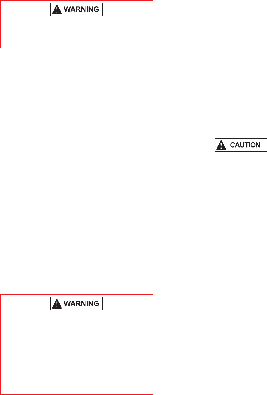
The driver is always responsible for the control
and safe operation of the vehicle at all times. The
Bendix® ABS system does not replace the need
for a skilled, alert professional driver, reacting
appropriately and in a timely manner, and using
safe driving practices.
FIGURE 1 - THE BENDIX® ESP® EC‑80™ CONTROLLER
Label Shows ECU
Designation
2
GENERAL SAFETY GUIDELINES
WARNING! PLEASE READ AND FOLLOW THESE INSTRUCTIONS
TO AVOID PERSONAL INJURY OR DEATH:
When working on or around a vehicle, the following guidelines should be observed AT ALL TIMES:
▲ Park the vehicle on a level surface, apply the
parking brakes and always block the wheels.
Always wear personal protection equipment.
▲Stop the engine and remove the ignition key
when working under or around the vehicle.
When working in the engine compartment,
the engine should be shut off and the ignition
key should be removed. Where circumstances
require that the engine be in operation, EXTREME
CAUTION should be used to prevent personal
injury resulting from contact with moving,
rotating, leaking, heated or electrically-charged
components.
▲Do not attempt to install, remove, disassemble
or assemble a component until you have read,
and thoroughly understand, the recommended
procedures. Use only the proper tools and
observe all precautions pertaining to use of those
tools.
▲If the work is being performed on the vehicle’s
air brake system, or any auxiliary pressurized air
systems, make certain to drain the air pressure
from all reservoirs before beginning ANY work
on the vehicle. If the vehicle is equipped with a
Bendix® AD-IS® air dryer system, a Bendix® DRM™
dryer reservoir module, or a Bendix® AD-9si™ air
dryer, be sure to drain the purge reservoir.
▲ Following the vehicle manufacturer’s
recommended procedures, deactivate the
electrical system in a manner that safely removes
all electrical power from the vehicle.
▲Never exceed manufacturer’s recommended
pressures.
▲Never connect or disconnect a hose or line
containing pressure; it may whip. Never remove
a component or plug unless you are certain all
system pressure has been depleted.
▲ Use only genuine Bendix® brand replacement
parts, components and kits. Replacement
hardware, tubing, hose, ttings, etc. must be of
equivalent size, type and strength as original
equipment and be designed speci cally for such
applications and systems.
▲Components with stripped threads or damaged
parts should be replaced rather than repaired.
Do not attempt repairs requiring machining or
welding unless speci cally stated and approved
by the vehicle and component manufacturer.
▲Prior to returning the vehicle to service, make
certain all components and systems are restored
to their proper operating condition.
▲ For vehicles with Automatic Traction Control
(ATC), the ATC function must be disabled (ATC
indicator lamp should be ON) prior to performing
any vehicle maintenance where one or more
wheels on a drive axle are lifted off the ground
and moving.
▲The power MUST be temporarily disconnected
from the radar sensor whenever any tests USING
A DYNAMOMETER are conducted on a Bendix®
Wingman® Advanced™-equipped vehicle.
▲ You should consult the vehicle manufacturer's operating and service manuals, and any related literature,
in conjunction with the Guidelines above.
Even with the Bendix® ESP® system with the EC-80™
Controller, the driver remains responsible for ensuring
vehicle stability during operation. The braking system
can only function within the limits of physics. The
system helps mitigate potential vehicle stability
incidents, but cannot prevent them in all cases.
Other factors such as driving too fast for road, trafc
or weather conditions, oversteering, an excessively
high vehicle Center of Gravity (CG), or poor road
conditions can cause vehicle instability that is beyond
the capability of any stability system to mitigate. In
addition, the effectiveness of Bendix ESP system
with the EC-80 Controller can be greatly reduced on
vehicles towing multiple trailer combinations.
The Bendix ESP system with the EC-80 Controller
(see page 12) may only be used on vehicles tested and
approved by Bendix engineering. The tests produce
a validated parameter data set for use by the vehicle’s
Bendix ESP EC-80 Electronic Control Unit (ECU).
When replacing an ECU, only specic Controllers —
with the correct parameter set — may be used. See
“Obtaining a New Bendix ESP EC‑80 Controller” on
page 17 for further details.
Bendix ESP system with the EC-80 Controller-equipped
vehicles should not be driven on high- banked roads —
such as those found on high-speed test or race tracks.
Test personnel must have the Bendix ESP system's
stability features disabled prior to operating a vehicle
on such tracks.
3
For vehicles with the (optional) Hill Start Aid (HSA) system
(sometimes referred to as a “Hill Start Assist”, or simply “Hill
Start”), this feature interfaces between the transmission
and the braking system. HSA helps the driver prevent
the vehicle from rolling downhill when moving up a steep
incline from a stationary position. See page 6 for more
information.
YAW CONTROL (YC)
A Bendix® EC‑80™ ESP® Controller includes Yaw Control
(YC) functionality. Yaw Control has the ability to apply
brakes to individual wheel ends, as well as applying the
trailer brakes, to counteract trailer “push” that — during
certain maneuvers — could lead to a loss‑of‑control or
a jackknife incident. See "Yaw Stability" on page 13 for
further details.
ROLL STABILITY PROGRAM (RSP)
The Bendix® Roll Stability Program (RSP), is an all‑axle
ABS solution that helps decrease vehicle speed by
reducing the engine's throttle and applying all vehicle
brakes as needed, mitigating the vehicle's tendency to
roll over. RSP focuses on reducing the vehicle’s speed
below the critical roll threshold during direction‑changing
maneuvers — such as driving on curved highway exit
ramps or obstacle avoidance maneuvers on dry, high
friction surfaces. See "ESP ABS with Stability Control"
on page 12 for further details.
During an RSP system intervention, the vehicle
automatically decelerates. RSP can slow the
vehicle with or without the operator applying
the brake pedal, and even when the operator is
applying the throttle.
COMPONENTS
The Bendix ESP EC‑80 Controller’s ABS function utilizes
the following components:
• Bendix® WS‑24™ Wheel Speed Sensors (four or
six, depending on the conguration), each with a
clamping sleeve. [Refer to SD-13-4860]
• Bendix® M‑40QR™ or M‑40‑HF™ Pressure Modulator
Valves (four, ve, or six may be present) [refer to
SD-13-4958]. For legacy systems where a Bendix®
M‑32™ or M‑32QR™ Pressure Modulator Valve is
used, refer to SD-13-4870.
• A dash‑mounted tractor ABS Indicator Lamp
• A service brake Relay Valve
• A dash‑mounted trailer ABS Indicator Lamp
• An optional blink code Activation Switch
• An optional ABS Off‑road Switch
The Bendix ESP EC‑80 Controller's ESP/RSP function
utilizes the following additional components:
• A Steer Axle Traction Control Valve (may be integral
to the service brake Relay Valve or a stand‑alone
device)
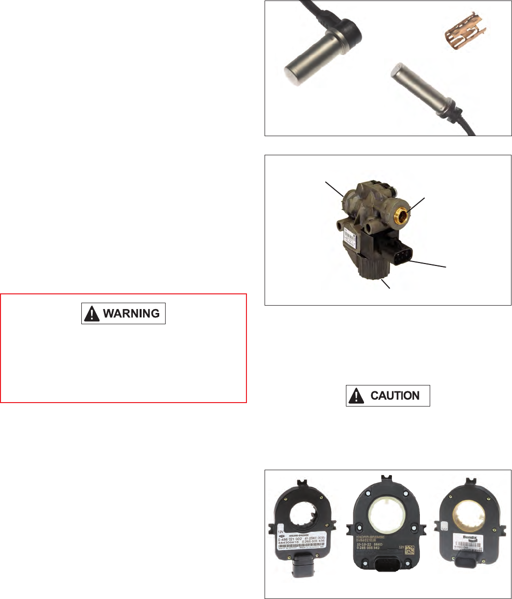
90° Speed
Sensors
Sensor
Clamping
Sleeve
Straight Speed
Sensors
FIGURE 2 - BENDIX® WS‑24™ WHEEL SPEED SENSORS
Delivery
(Port 2) Supply
(Port 1)
Exhaust (Port 3)
Electrical
Connector
M-40X™
Modulator
FIGURE 3 - EXAMPLE OF A BENDIX M‑40X™ MODULATOR
• A dash‑mounted ESP Status/Indicator Lamp (also
serves as the ATC Status/Indicator Lamp)
• A Bendix® SAS‑60™ Steering Angle Sensor
(mounted to the steering column ‑ See Figure 4)
When replacing a steering wheel, take care not to
damage the Steering Angle Sensor or interfere with
its operation, and the Steering Angle Sensor must be
recalibrated (see Troubleshooting section.)
Straight
Connector
90° Connectors
FIGURE 4 - EXAMPLES OF STEERING ANGLE SENSORS
4
• Bendix® YAS‑60™ or YAS‑70X™ Yaw Rate/Lateral
Acceleration Sensors (typically mounted to a cross‑
member near the back of the vehicle cab). See
Figure 5.
• Brake Demand Sensors (installed in the primary
and secondary delivery circuits)
• A Load Sensor (typically installed in the suspension
air bag)
• An additional Modulator Valve (Bendix® M‑40QR™ or
M‑40HF™ Pressure Modulator Valve) that controls
the pressure applied to the trailer brakes during a
system intervention
The Bendix® ESP® EC‑80™ Controller's ATC function
utilizes the following additional components:
• A drive axle Traction Control Valve (may be integral
to the service brake relay valve or a stand‑alone
device)
• A dash‑mounted ATC Status/Indicator Lamp
• A J1939 serial communication Control Module
• A J1939‑ or ECU hardware‑provided Stop Lamp
Switch Input
• An optional ATC Mud/Snow Switch (sometimes
referred to as an ATC off‑road switch)
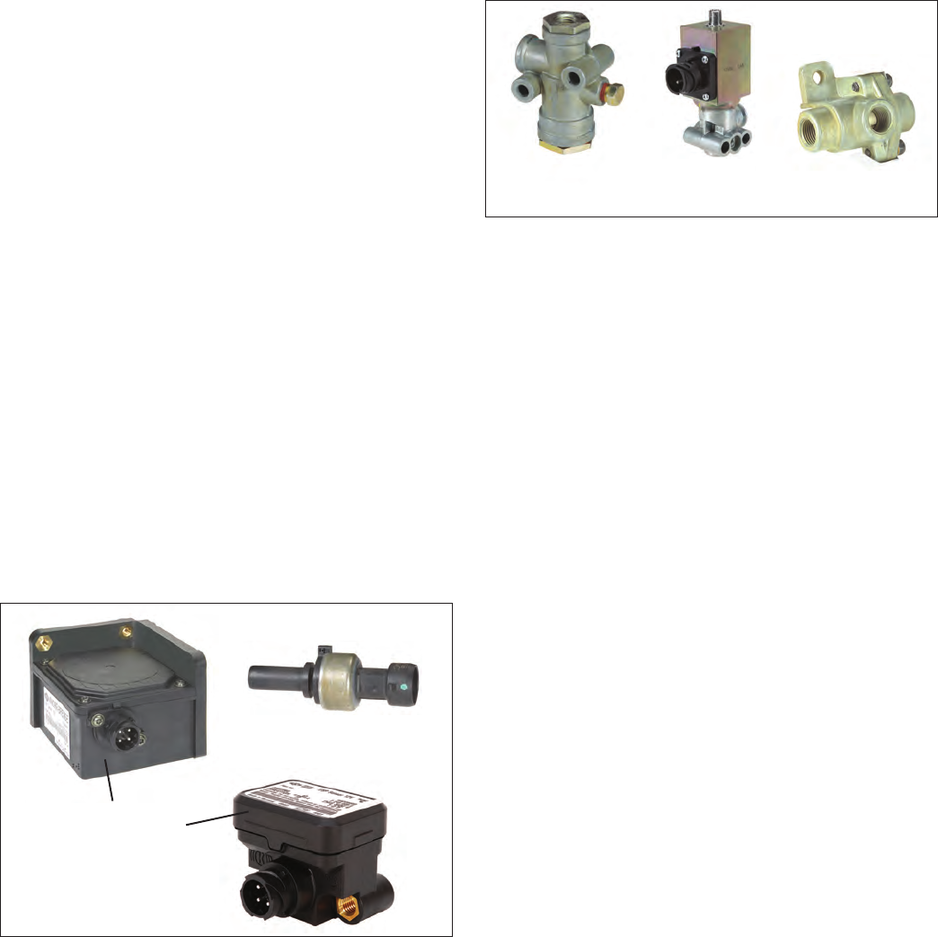
Yaw/Lateral
Accelerator Sensors
(Two examples
shown.)
Brake Demand/
Load Sensor
FIGURE 5 - YAW AND BRAKE DEMAND/LOAD SENSORS
The Bendix ESP EC‑80 Controller's Hill Start Aid function
utilizes the following additional components:
• A Bendix® AT‑3™ Traction Control Valve
• A dash‑mounted Hill Start Status/Indicator Lamp
• A dash‑mounted Enable/Disable Switch
• A Bendix® RV‑3™ Pressure Reducing Valve
• A Bendix® DC‑4® Double Check Valve
Bendix® RV-3™
Pressure
Reducing Valve
Bendix® AT-3™
Traction Control
Valve
Bendix® DC-4®
Double Check
Valve
FIGURE 6 - ADDITIONAL VALVES NECESSARY FOR THE
HILL START AID FEATURE
BENDIX® ETRAC™ AUTOMATED AIR
SUSPENSION TRANSFER SYSTEM
The Bendix® eTrac™ automated air pressure transfer system
is used on 6 x 2 semi‑tractors that feature Bendix® ATC
and ESP Antilock Brake Systems (ABS). This system
complements the Bendix® SMART ATC™ traction control
feature of our ABS system to provide improved traction at
low speeds (e.g. pulling away on an inclined ramp, or in
slippery conditions such as mud or snow‑covered surfaces,
etc.) When active, the Bendix eTrac system vents — or
“dumps” — the air pressure of the tag axle suspension
air bags, and increases the air pressure in the drive axle
suspension air bags to a pre‑determined maximum. This
action helps the drive axle to gain more traction.
See SD-13-21021 for more information about the Bendix®
eTrac™ Automated Air Suspension Transfer System.
ECU MOUNTING
The Bendix ESP EC‑80 Controller is not protected against
moisture, and must be mounted in an environmentally
protected area.
All wire harness connectors must be properly seated. The
use of secondary locks is strongly recommended.
The Bendix ESP EC‑80 Controller utilizes connectors from
the AMP MCP 2.8 product family.
HARDWARE CONFIGURATIONS
Bendix ESP EC‑80 Controllers support applications up to
six sensor/six modulator (6S/6M) installations with ATC
and drag torque control. They can also support Hill Start
functions. All 12 volt models support Power Line Carrier
(PLC). 24 volt models do not support PLC. See Figure 7
for more details.
5
ABS
Off-
Road ATC ATC
Mud/Snow Blink
Codes ESP/
RSP
HSA
Hill Start
Aid Feature
Bendix®
eTrac™
system*
Input
Voltage PLC Modu-
lators
(PMVs)
Retarder
Relay Sensors
Serial
Communication
J1939
Optional Optional Optional 12/24 4/5/6 4/6
* For information about the Bendix® eTrac™ automated air suspension transfer system, see SD‑13‑21021
FIGURE 7 - BENDIX® ESP® EC‑80™ CONTROLLER FEATURES
BENDIX® ESP® EC-80™ CONTROLLERS USE
POWER LINE CARRIER (PLC)
All new towing vehicles built since March 1, 2001, have had
an in‑cab trailer ABS Indicator Lamp installed.
Trailers built since March 1, 2001, transmit the status of
the trailer ABS over the power line (the blue wire of the
J560 connector) to the tractor using a Power Line Carrier
(PLC) signal. See Figures 8 and 9. Typically the signal is
broadcast by the trailer ABS Electronic Control Unit (ECU).
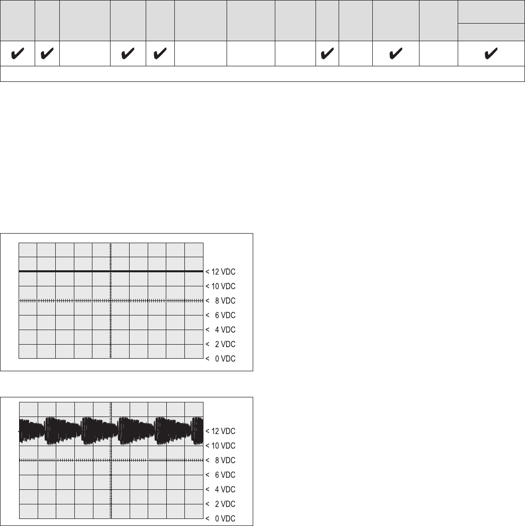
FIGURE 8 - POWER LINE WITHOUT PLC SIGNAL
FIGURE 9 - POWER LINE WITH PLC SIGNAL
The application of PLC technology for the heavy vehicle
industry in North America is known as “PLC4Trucks.”
The Bendix® ESP® EC‑80™ Controller supports PLC
communications in accordance with SAE J2497.
PLC SIGNAL
An oscilloscope can be used to measure or identify the
presence of a PLC signal on the power line. The PLC
signal is an amplitude and frequency‑modulated signal.
Depending on the ltering and load on the power line,
the PLC signal amplitude can range from 5.0 mVp‑p to
7. 05 Vp ‑ p.
Suggested oscilloscope settings are AC coupling, with one
volt/div, 100 µsec/div. The signal should be measured at
the ignition power input of the Bendix EC‑80 Controller.
Note: An ABS trailer equipped with PLC, or a PLC
diagnostic tool, must be connected to the vehicle in order
to generate a PLC signal on the power line.
BENDIX ESP EC-80 CONTROLLER INPUTS
Battery and Ignition Inputs
The Bendix ESP EC‑80 Controller operates at a nominal
supply voltage of 12 or 24 volts, depending on the ECU.
The battery input is connected through a 30 amp fuse
directly to the battery.
The ignition input is applied by the ignition switch circuit
through a 5 amp fuse.
Ground Input
The Bendix ESP EC‑80 Controller supports one ground
input. See pages 52 and 53 for wiring system schematics.
ABS Indicator Lamp Ground Input
The Bendix ESP EC‑80 Controller requires a second
ground input (X1‑12) for the ABS indicator lamp. The X1
wire harness connector contains an ABS indicator lamp
interlock (X1‑15), which shorts the ABS indicator lamp
circuit (X1‑18) to ground if the connector is removed from
the ECU.
Bendix® WS-24™ Wheel Speed Sensors
Wheel speed data is provided to the Bendix ESP EC‑80
Controller from the Bendix® WS‑24™ wheel speed sensor
(see Figure 2). Vehicles have an exciter ring (or “tone
ring”) as part of the wheel assembly. As the wheel
turns, the teeth of the exciter ring pass the wheel speed
sensor, generating an AC signal. The Bendix ESP EC‑80
Controller receives the AC signal, which varies in voltage
and frequency as the wheel speed changes.
Vehicle axle configurations determine the number of
Bendix WS‑24 wheel speed sensors that must be used.
A vehicle with a single rear axle requires four wheel speed
sensors. Vehicles with two rear axles can utilize six wheel
speed sensors for optimal performance.

6
Diagnostic Blink Code Switch
A momentary switch that grounds the ABS Indicator Lamp
output is used to place the ECU into the diagnostic blink code
mode and is typically located on the vehicle’s dash panel.
Optional ABS Off-Road Switch and Indicator
Lamp Operation
Vehicle operators use an optional dash‑mounted switch to
place the Bendix® ESP® EC‑80™ Controller into the ABS
off‑road mode. See "Optional ABS Off-Road Mode" on
page 10 for further details. In some cases, ECUs may
also be put into the ABS off‑road mode by one of the other
vehicle control modules, using a J1939 message to the
Bendix ESP EC‑80 Controller.
(If you need to know if a specic Bendix ESP EC‑80
Controller uses a J1939 message to operate the lamp,
contact the Bendix Tech Team. E‑mail the Tech Team
at ABS@bendix.com (be sure to specify the ECU part
number), or call 1‑800‑AIR‑BRAKE (1‑800‑245‑2725).
The ABS off-road mode should not be used on
normal, paved road surfaces because vehicle
stability and steerability may be adversely affected.
When the ECU is placed in the ABS off-road mode,
the ABS Indicator Lamp will ash constantly (at a
rate of once per 2.5 seconds) to notify the vehicle
operator that the off-road mode is active.
Optional ATC Mud/Snow (Off-Road) Switch and
Indicator Lamp Operation (also see page 8.)
The Bendix ESP system uses a dash‑mounted switch for the
operator to place the ECU into the ATC Mud/Snow mode.
Optional Hill Start/Hill Start Assist Feature
Switch and Lamp Operation (see also page 8.)
ESP Controllers use a dash‑mounted switch for the
operator to place the ECU into the hill start mode. This
feature interfaces between the transmission and the
braking system to help the driver prevent the vehicle from
rolling downhill when moving up a steep incline from a
stationary position.
With Hill Start Aid Feature option you lose the ABS
off-road function and the retarder relay output.
When the ECU is placed in the Hill Start Aid (HSA) feature
mode, the HSA Indicator Lamp will ash constantly (at a
rate of once per 2.5 seconds) to notify the vehicle operator
that the HSA mode is active. The ECU receives J1939
messages from the transmission to engage the HS/HSA
components. When engaged, the system applies 44 psi to
the rear brakes for three (3) seconds then releases. This
function is totally controlled by the automatic transmission.
Stop Lamp Switch (SLS)
The Bendix ESP EC‑80 Controller monitors the vehicle
stop lamp status. Certain vehicle functions, such as
ATC and All‑Wheel Drive (AWD), use the status of the
stop lamp to determine when the driver makes a brake
application. This can be provided to the ECU via J1939
communications, or hardware input.
Brake Demand Sensors
The brake demand sensors provide the Controller with an
indication of driver‑applied brake pressure. One is installed
in the primary air brake circuit, and another is installed in
the secondary air brake circuit.
Load Sensor
The load sensor provides the Controller with an indication
of the vehicle load. It is typically installed in one of the
suspension air bags.
Bendix® SAS-70X™ Steering Angle Sensor
Bendix® brand Steering Angle Sensors (SAS) are used to
report the steering wheel position to the Controller, utilizing
a dedicated serial communications link that is shared with
the Yaw Rate Sensor. The Controller supplies the power
and ground inputs to the Bendix® SAS‑70X™ sensor.
The Bendix SAS‑70X sensor is available with two different
styles of wire harness connectors. (See Figure 4.)
Bendix® YAS-60™ or YAS-70X™ Yaw Rate/Lateral
Acceleration Sensors
Bendix® brand yaw rate/lateral acceleration sensors are
used to provide the Controller an indication of vehicle
lateral acceleration and rotation around the vertical axis.
This information is provided to the Controller, utilizing a
dedicated serial communications link that is shared with
the Bendix® SAS‑60™ sensor. The Controller supplies the
power and ground inputs to the yaw rate sensor.
BENDIX® ESP® EC-80™ CONTROLLER
OUTPUTS
Bendix® M-40QR™ and M-40HF™ Pressure
Modulator Valves (PMVs)
The Bendix ESP EC‑80 Controller operates Bendix®
M‑40QR™ and M‑40HF™ Pressure Modulator Valves
(PMVs) to modify the driver‑applied air pressure to the
service brakes during ABS, ATC, RSP or YC activation
(see pages 9-13). The PMV is an electropneumatic
control valve and is the last valve that air passes through
on its way to the brake chamber. The modulator hold and
release solenoids are activated to "modulate" or "control"
the brake pressure during an antilock braking event. The
hold solenoid is normally open and the release solenoid is
normally closed, such that the PMV nominally allows air to
ow through. This design allows for air delivery to brake
chambers in the event of electrical trouble.
7
The Bendix® ESP® EC‑80™ Controller also utilizes an
additional Pressure Modulator Valve (PMV) for control
of the trailer service brakes during stability interventions.
Traction Control Valve (TCV)
Bendix ESP EC‑80 Controllers use two TCVs, one on the
steer axle and one on the drive axle. The TCV may be a
separate valve or integrated into the rear axle relay valve.
The Controller will activate the drive axle TCV during
differential braking ATC events.
During stability interventions, the Controller will activate
both the steer axle and drive axle TCVs as required.
Stop Lamp Output
The Controller provides an output to control a relay
that illuminates the vehicle stop lamps during stability
interventions. This information is also available using the
J1939 serial communications link.
ABS Indicator Lamp Control with Optional
Diagnostic Blink Code Switch
The Bendix ESP EC‑80 Controller has internal circuitry to
control the ABS Indicator Lamp on the dash panel.
The ABS Lamp Illuminates:
1. During power up (e.g. when the vehicle is started) for
approximately three (3) seconds and turns off after the
self‑test is completed, providing no Diagnostic Trouble
Codes (DTCs) are present on the ECU;
2. When full ABS operation is not available due to the
presence of a DTC on the ECU;
3. If the ECU is unplugged or has no power;
4. When the ECU is placed into the ABS off‑road
mode (the lamp ashes steadily at a rate of once per
2.5 sec.); or
5. To display blink codes for diagnostic purposes after the
external diagnostic switch is activated.
The Bendix ESP EC‑80 Controller may communicate
with other vehicle control modules to operate the ABS
Indicator Lamp using serial communications. (If you
need to know if this Bendix ESP EC‑80 Controller uses
serial communications to operate the lamp; e‑mail ABS@
bendix.com, (be sure to specify the ECU part number), or
call 1‑800‑AIR‑BRAKE/1‑800‑247‑2725 and speak to the
Bendix Tech Team.)
Indicator Lamp Control Using Serial
Communications Links
As mentioned above, depending on the vehicle
manufacturer, the dash indicator lamps (ABS, ATC,
ESP, and trailer ABS) may be controlled using serial
communications links. In these cases, the Bendix ESP
EC‑80 Controller will send a serial communications
message over the J1939 link, indicating the required status
of the lamp(s). Another vehicle control module receives
the message and controls the indicator lamp(s).
Dynamometer Mode Indicator Lamp Operation
When the Bendix ESP EC‑80 Controller is put into the
Dynamometer mode for testing purposes, the ATC
Indicator Lamp will be illuminated.
Retarder Relay Disable Output
The retarder relay disable output may be used to control a
retarder disable relay. When congured to use this output,
the ECU will energize the retarder disable relay and inhibit
the use of the retarder as needed.
If the ECU is congured for the Hill Start/ Hill Start Assist
feature (HS/HSA), the retarder relay output pin is used to
control the Hill Start status lamp. As a result, the vehicle
loses the retarder relay function when it has the Hill Start
feature.
SAE J1939 Serial Communications
A Controller Area Network (CAN) data link (SAE J1939) is
provided for communication. This link is used for various
functions, such as:
• Diagnostic purposes.
• To disable retarding devices during ABS operation.
• To request that the torque converter disable lock‑up
during ABS operation
• To share information such as wheel speed and ECU
status with other vehicle control modules.
Bendix ESP EC‑80 Controllers utilize the J1939 data link
for:
• ATC and drag torque control functions.
• Vehicle stability functions.
Trailer ABS Indicator Lamp Control
The Bendix ESP EC‑80 Controller will activate a trailer ABS
Indicator Lamp (located on the dash panel) that indicates
the status of the trailer ABS unit on one, or more trailers, or
dollies that are equipped with PLC functionality. Typically,
the Bendix ESP EC‑80 Controller directly controls the
trailer ABS Indicator Lamp based on the information it
receives from the trailer ABS, via PLC.
Alternatively, some vehicles require the Bendix ESP EC‑80
Controller to activate the trailer ABS Indicator Lamp by
communicating with other vehicle Controllers using serial
communications.
(If you need to know if this Bendix ESP EC‑80 Controller
uses a serial communications message to operate the
lamp, e‑mail ABS@bendix.com (be sure to specify the ECU
part number), or call 1‑800‑AIR‑BRAKE (1‑800‑245‑2725)
and speak to the Bendix Tech Team.)
Interaxle Differential Lock Control
(AWD Transfer Case)
Bendix ESP EC‑80 Controllers can control the interaxle
differential lock (AWD transfer case). This is recommended
on AWD vehicles, but the ECU must be specially congured
to provide this feature. E‑mail ABS@bendix.com for more
details.
8
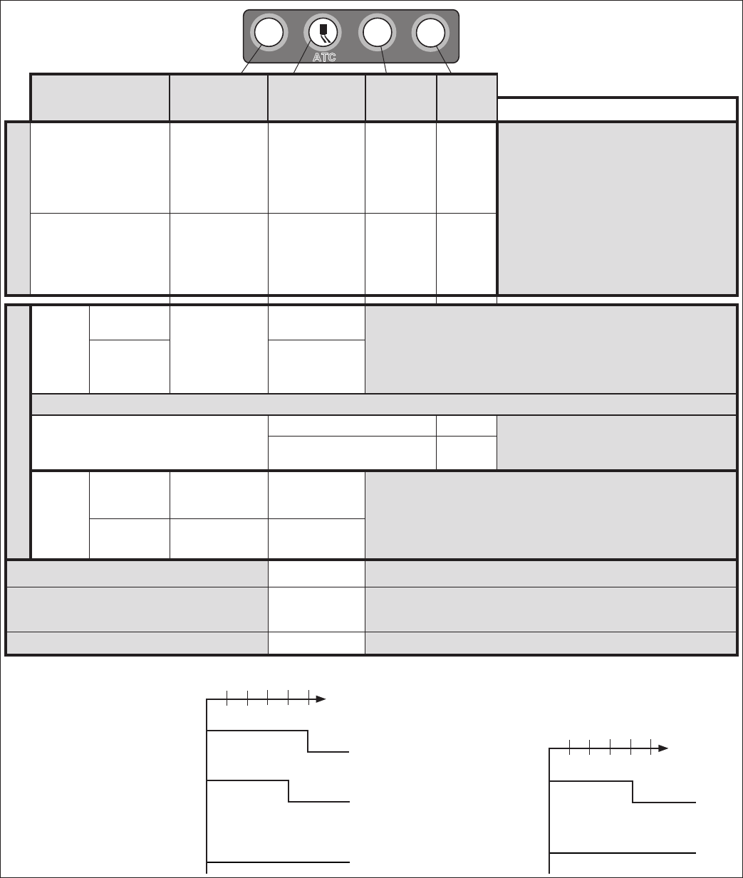
INDICATOR LAMPS AND POWER-UP
SEQUENCE
NOTICE: The vehicle operator should Verify the proper
operation of all installed indicator lamps (ABS, ATC/ESP,
and trailer ABS) when applying ignition power and during
vehicle operation. See Figure 10.
Lamps that do not illuminate as expected when ignition
power is applied, or remain illuminated, indicate the need
for maintenance.
ABS System
Status Indicators
at Start-Up
Trailer ABS
Indicator Lamp
(PLC Detected)**
Trailer ABS
Indicator Lamp**
(PLC Not Detected)
Powered Vehicle ABS
Indicator Lamp
Power
Application
ON
OFF
ON
OFF
0.5 2.0 2.5 3.0 (sec.)1.5
ON
OFF
ATC/ESP
enabled
No ESP
or ATC
ATC/ESP System
Status Indicator
at Start-Up
ON
OFF
Power
Application
ON
OFF
0.5 2.0 2.5 3.0 (sec.)1.5
FIGURE 10 - BENDIX® ESP® EC‑80™ CONTROLLER INDICATOR LAMP BEHAVIOR
Mode ABS
Lamp ATC/ESP Lamp Trailer
ABS Lamp HSA
Lamp Comments
At Vehicle Startup
Ignition on ‑ start up
[trailer with Power Line
Carrier (PLC)]
ON for
three (3)
seconds*
ON for 2.5
seconds*
ON for
three (3)
seconds**
ON for
three (3)
seconds*
* If any of the described lamp behaviors
do not occur — or if the lamp remains
on during operation — have the vehicle
serviced by a qualied mechanic as
soon as possible to restore full system
functionality.
** Some vehicle manufacturers may
illuminate the trailer ABS indicator lamp
at power‑up regardless of whether a
PLC signal is detected from the trailer or
not. Consult the vehicle manufacturer’s
documentation for more details.
3 seconds after ignition
[with no Diagnostic
Trouble Codes (DTCs)] Lamp OFF*Lamp OFF*Lamp OFF** Lamp
OFF*
Special Mode Operation
ABS
Off-Road
Mode
Normal
Lamp ashes
slowly (every 2.5
seconds)
Lamp OFF • Uses dash switch
• Not for rm road surfaces
• Allows more wheel lock‑up (less ABS intervention)
• Mode only applies under 25 mph (Over 25 mph, the system reverts to
full ABS ‑ including ATC/ESP — and upon exiting off‑road mode, the
ATC lamp extinguishes.)
During an ATC
Event Flashes quickly
‑— OR, depending on vehicle options (a vehicle can have either ABS off‑road or HSA) —
Vehicles with Hill Start Aid (HSA):
During HSA Mode
(“Hill Start” / “Hill Start Assist”)
During HSA Event Lamp OFF • The HSA lamp is illuminated only at power‑
up, or if an HSA DTC is present
HSA Manually Disabled Flashes
slowly
Deep
Mud/
Snow/
Mode
Normal OFF Flashes slowly
(every 2.5
seconds) • Uses dash switch
• Increases allowable wheel slip during ATC interventions
• Not for rm road surfaces
During an
ATC/ESP
Event OFF Flashes quickly
During an Automatic Traction Control (ATC) Event Flashes quickly • Reduces wheel slip during acceleration at low speeds
During Dynamometer Mode Lamp ON
(ATC
Disabled)
• Disables ATC monitoring functions
• When not in Dynamometer Mode, an illuminated lamp indicates an
ATC DTC is present
During an ESP Event Flashes quickly •
System intervenes to reduce the risk of rollovers, loss‑of‑control, etc.
Dash Lamp Behavior for the
Bendix® ESP® EC-80™ Controller
TRLR
ABS
ATC
HSA

9
ABS Indicator Lamp Operation (Bulb Check)
The Bendix® ESP® EC‑80™ Controller will illuminate the
ABS Indicator Lamp for approximately three seconds when
ignition power is applied, after which the lamp will extinguish
if no Diagnostic Trouble Codes (DTCs) are detected.
The Controller will illuminate the ABS Indicator Lamp
whenever full ABS operation is not available due to a DTC.
In most cases, partial ABS is still available.
ATC/ESP Status/Indicator Lamp Operation
The Bendix ESP EC‑80 Controller will illuminate the ATC/
ESP lamp for approximately 2.5 seconds when ignition
power is applied, after which the lamp will extinguish if
no DTCs are detected. The Controller will continuously
illuminate the ATC/ESP Indicator Lamp whenever ESP or
ATC is disabled due to a DTC.
During an ESP or ATC intervention, the lamp will ash
rapidly (2.5 times per second). When the Controller is
placed in the ATC Mud/Snow (off‑road) mode, the lamp
will ash slowly at a rate of once every 2.5 seconds.
Trailer ABS Indicator Lamp Operation
The Controller will control the Trailer ABS Indicator Lamp
when a PLC signal (SAE J2497) from a trailer ABS ECU
is detected.
Hill Start Assist (HSA) Indicator Lamp Operation
Vehicles with HSA enabled, will illuminate the HSA
Indicator Lamp when ignition power is applied. The lamp
will extinguish if there are no issues with the HSA system.
Pressure Modulator Valve (PMV) and Traction
Control Valve (TCV) Chuff Test
Driver
Right Steer
Left Steer
Right
Additional
Left
Additional
Right Drive
Left Drive
FIGURE 11 - VEHICLE ORIENTATION (TYPICAL)
After the performance of the conguration test, the Bendix
ESP EC‑80 Controller will perform a Bendix‑patented PMV
and TCV Chuff Test. The Chuff Test is an electrical and
pneumatic PMV test that can assist maintenance personnel
in verifying proper PMV wiring and installation.
When ignition power is applied, each modulator solenoid
is briey energized. If the air system is fully charged and
the service brake pedal is depressed during ignition, the
modulator creates a single, sharp audible “chuff” of air
pressure. The modulators are energized in a certain
pattern: right front; left front; right rear; then left rear.
This test is performed only when the vehicle is stationary
(if the vehicle moves, the Chuff Test will not be performed).
The Bendix ESP EC‑80 Controller will perform a PMV
Chuff Test on all installed modulators in the following order:
• Steer Axle Right PMV;
• Steer Axle Left PMV;
• Drive Axle Right PMV;
• Drive Axle Left PMV;
• Additional Axle Right PMV;
• Additional Axle Left PMV; then
• Drive Axle TCV
The pattern will then repeat itself. See Figure 11.
Vehicles with a Bendix ESP EC‑80 Controller — following
the completion of the second round of PMV & TCV Chuff
Tests — the Controller (if congured to do so) will perform
a test to cross‑check the trailer PMV operation with the
vehicle stop lamps. If the trailer PMV circuit is mis‑wired
(including the steer axle TCV), the PMV will exhaust a large
amount of air, or none at all.
NOTICE: If there are any active DTCs, the stop lamp
cross‑check portion of the Chuff Test will not be carried out
until all DTCs are fully diagnosed and the corresponding
repairs are successfully conducted. The ESP/ATC dash
indicator will also illuminate when there are active ABS,
ATC or ESP DTCs.
The ECU will not perform the PMV Chuff Test when wheel
speed sensors show that the vehicle is in motion.
ABS OPERATION
Bendix® ABS uses wheel speed sensors, ABS pressure
modulator valves, and an ECU to control either four or six
wheels of a vehicle. The Bendix ESP EC‑80 Controller
monitors individual wheel turning motion during braking,
and adjusts or modulates the brake pressure at the wheel
end. When excessive wheel slip — or wheel lock‑up — is
detected, the Bendix ESP EC‑80 Controller will activate
the pressure modulator valves to automatically reduce
the brake pressure at one or more of the wheel ends.
By these actions, the ABS system helps to maintain the
vehicle's lateral stability and steerability during heavy brake
applications and during braking on slippery surfaces.
Steer Axle Control
Although both wheels of the steer axle have their own
wheel speed sensor and pressure modulator valve, the
Bendix ESP EC‑80 Controller blends the applied braking
force between the two steering axle brakes. This Bendix
patented brake application control, called Modified
Individual Regulation (MIR), is designed to help reduce
steering wheel pull during an ABS event on road surfaces
with poor traction, or areas of poor traction (e.g. asphalt
road surfaces with patches of ice).
10
Single Drive Axle Control (4x2 Vehicle)
For vehicles with a single rear drive axle (4x2), the brakes
are operated independently by the Bendix® ESP® EC‑80™
Controller, based on the individual wheel behavior.
Dual Drive Axle Control (4S/4M Conguration)
For vehicles with dual drive axles (6x4) using a 4S/4M
conguration, one ABS modulator controls both of the
right‑side rear wheels; the other modulator controls both
of the left‑side rear wheels. Both wheels on each side
receive equal brake pressure during an ABS stop. The
rear wheel speed sensors must be installed on the axle
with the lightest load.
Dual Rear Axle Control (6S/6M Conguration)
For vehicles with dual rear axles (6x4, 6x2) using a 6S/6M
conguration, the rear wheels are controlled independently.
Therefore, brake application pressure at each wheel is
adjusted according to the individual wheel behavior on
the road surface.
6x2 Vehicles with 6S/5M Conguration
6x2 vehicles can utilize a 6S/5M conguration, with the
additional axle (a non‑driven rear axle) having two sensors,
but only one Pressure Modulator Valve (PMV). In this case,
the PMV controls both wheels on the additional axle. The
additional axle wheels would receive equal brake pressure,
based on the wheel that is currently experiencing the most
wheel slip.
Normal Braking
During normal braking, brake pressure is delivered through
the ABS PMV and into the brake chamber. If the ECU
does not detect excessive wheel slip, it will not activate
ABS control, and normal vehicle service braking is applied.
Retarder Brake System Control
On surfaces with low traction, application of the retarder
can lead to high levels of wheel slip at the drive axle wheels,
which can adversely affect vehicle stability.
To prevent this, the Bendix ESP EC‑80 Controller switches
off the retarder as soon as a lock‑up is detected at one (or
more) of the drive axle wheels.
When the ECU is placed in the ABS off‑road mode (on
vehicles equipped with this optional feature), it will switch
off the retarder only when ABS is active on a steer axle
wheel and a drive axle wheel.
Optional ABS Off-Road Mode
On some road conditions, particularly when the driving
surface is soft, the stopping distance with conventional
ABS may be longer than without ABS. This can occur
when a locked wheel on soft ground or loose gravel plows
up the road surface in front of the tire, changing the rolling
friction value. Although vehicle stopping distance with a
locked wheel (in the absence of ABS) may be shorter than
corresponding stopping distance with conventional ABS
control, vehicle steerability and stability would be reduced.
Bendix ESP EC‑80 Controllers have an optional dash
switch that initiates a modied ABS control mode (known
as "off‑road ABS") that more effectively accommodates
these soft road conditions to shorten stopping distance
while maintaining optimal vehicle steerability and stability.
Note: Off‑road mode is not available if the vehicle is
equipped with Hill Start / Hill Start Assist (HS or HSA).
The ABS off-road mode should not be used on
normal, paved road surfaces because vehicle
stability and steerability may be reduced. The ABS
Indicator Lamp will ash slowly to indicate to the
driver that the ABS off-road mode is engaged.
When ABS off-road mode is engaged, stability
functions are disabled at speeds below approximately
25 mph/40 kph. The ATC/ESP dash lamp will illuminate
to indicate to the driver that the stability system is
disabled.
The vehicle manufacturer should provide the optional ABS
off‑road function only for vehicles that operate on unpaved
surfaces — or that are used in off‑road applications — and
is responsible for ensuring that vehicles equipped with the
ABS off‑road function meet all FMVSS‑121 requirements
and have adequate operator indicators and instructions.
The vehicle operator activates the off‑road function with a
switch on the dash panel. A ashing ABS Indicator Lamp
indicates to the driver that the ABS off‑road function is
engaged. To exit the ABS off‑road mode, depress and
release the switch. A new ignition cycle will also cause
the ECU to exit the ABS off‑road mode.
All-Wheel Drive (AWD) Vehicles
AWD vehicles with an engaged interaxle differential (steer
axle to rear axle) / AWD transfer case, may have negative
effects on ABS performance. Optimum ABS performance
is achieved when the lockable differentials are disengaged,
allowing individual wheel control.
Bendix ESP EC‑80 Controllers can be programmed
specically for this conguration to control the differential
lock/unlock solenoid in the AWD transfer case. When
programmed to do so, the ECU will disengage the locked
interaxle/AWD transfer case during an ABS event and
reengage it once the ABS event has ended.
11
ATC OPERATION
ATC Functional Overview
Just as ABS improves vehicle stability during braking,
Automatic Traction Control (ATC) improves vehicle stability
and traction during vehicle acceleration. The Bendix®
ESP® EC‑80™ Controller's ATC function uses the same
wheel speed information and modulator control as the
ABS function. The Bendix ESP EC‑80 Controller detects
excessive drive wheel speed; compares the speed to the
front, non‑driven wheels; and reacts to help bring the wheel
spin under control. The Controller can be congured to use
engine torque limiting and/or differential braking to control
wheel spin. For optimal ATC performance, both methods
are recommended.
ATC/ESP Lamp Output/ATC Mud/Snow Switch
Input
Bendix ESP EC‑80 Controllers operate the ATC/ESP dash
lamp as follows.
The ATC/ESP dash lamp illuminates:
1. During power up (e.g. when the vehicle is started) for
approximately 2.5 seconds and turns off after the self
test is completed, providing no Diagnostic Trouble
Codes (DTCs) are present.
2. When ESP or ATC is disabled for any reason.
3. During an ESP or ATC event (the lamp will ash rapidly
at a rate of 2.5 times per second).
4. When the ECU is placed in the ATC off‑road mode
(the lamp will ash steadily at a rate of once every 2.5
seconds). This noties the vehicle operator that the
ATC Mud/Snow mode is active.
5. When the ECU is placed in the ABS off‑road mode.
When in this mode, ESP will be disabled below 25 mph
and its inactive status will be indicated by a steadily
illuminated ATC/ESP lamp.
Differential Braking
Differential braking within ATC is automatically activated
when drive wheel(s) on one side of the vehicle are spinning
excessively. This typically occurs on road surfaces
with patches of ice. The traction system will then lightly
apply the brake to the drive wheel(s) that are spinning
excessively. The vehicle differential will then drive the
wheels on the other side of the vehicle.
Differential braking (as part of ATC functionality) is available
at vehicle speeds up to 25 mph/40 kph.
Disabling ATC Differential Braking
ATC differential braking is disabled under the following
conditions:
1. During power up (e.g. when the vehicle is started), until
the ECU detects a service brake application.
2. If the ECU receives a J1939 message indicating that
the vehicle is parked.
3. When the dynamometer test mode is active. The
Dynamometer test mode is entered using the diagnostic
Blink Code Switch or by using a diagnostic tool (such
as Bendix® ACom® Diagnostics).
4. In response to a serial communications request from
a diagnostic tool.
5. If ATC Differential Braking function is activated for a
long time period to avoid overheating of the brakes. It
would take approximately three (3) continuous minutes
of activation for the time‑out to occur. Once timed‑out,
approximately two (2) minutes of "cool off" time would
be required before ATC Differential Braking can be used
again.
6. When certain DTC conditions are detected.
Traction Control with Engine Torque Limiting
The Bendix ESP EC‑80 Controller uses Engine Torque
Limiting to control drive‑axle wheel slip. This is commu‑
nicated to the engine control module (using J1939), and
is available at all vehicle speeds.
Bendix® SMART ATC™ System
The Bendix ESP EC‑80 Controller has an additional feature
known as the Bendix® SMART ATC™ system. This system
monitors the accelerator pedal position (using J1939)
to help provide optimum traction and vehicle stability.
By determining the driver’s throttle input and adapting the
target slip of the drive wheels to the driving situation, the
Bendix SMART ATC system allows higher wheel slip when
the accelerator pedal is applied above a preset level.
The wheel slip allowed by the Bendix SMART ATC system
is decreased when driving through a curve for improved
stability.
Disabling ATC Engine Control and the Bendix
SMART ATC System
ATC Engine Control and the Bendix SMART ATC system
will be disabled under the following conditions:
1. In response to a serial communications request from
an off‑board tool;
2. At power‑up until the ECU detects a service brake
application;
3. If the ECU receives a J1939 message indicating that
the vehicle is parked;
4. If the dynamometer test mode is active. This may be
accomplished via an off‑board tool or the diagnostic
Blink Code Switch; or
5. When certain DTC conditions are detected.

12
Optional ATC Mud/Snow (Off-Road) Mode
In some road conditions, the vehicle operator may desire
additional drive wheel slip when ATC is active. The Bendix®
ESP® EC‑80™ Controller has an optional control mode to
permit this desired performance.
The vehicle operator can activate the Mud/Snow function
with a switch on the dash panel. Alternately, a J1939
message may be used to place the vehicle in this mode.
The ATC/ESP Indicator Lamp will ash steadily at a rate
of once every 2.5 seconds to conrm that the ATC mud/
snow mode is engaged.
To exit the ATC Mud/Snow mode, depress and release the
ATC Mud/Snow switch.
Drag Torque Control Functional Overview
Bendix ESP EC‑80 Controllers have a feature referred to
as drag torque control which reduces wheel slip on a driven
axle due to driveline inertia. This condition is addressed
by increasing the engine torque to overcome the inertia.
Drag torque control increases vehicle stability on low‑
traction road surfaces during down‑shifting or retarder
braking.
FIGURE 13 - YAW CONTROL EXAMPLE
A Real World Example Of How Yaw Control
Operates:
Excessive speed exceeds the threshold, creating a
situation where a vehicle is likely to spin and jackknife.
The Bendix® Yaw Control system reduces engine throttle
and selectively applies brakes to reduce the tendency
to jackknife.
FIGURE 12 - RSP EXAMPLE
A Real World Example
Of How The RSP
System Operates:
Excessive speed for road
conditions creates forces
that exceed the threshold
at which a vehicle is likely
to rollover on a higher‑
friction surface.
The system automatically reduces
engine torque and applies the
service brakes (based on the
projected rollover risk) to reduce
the vehicle speed, thereby
reducing the tendency to roll over.
BENDIX ESP EC-80 ABS WITH STABILITY
CONTROL
Overview
The Bendix ESP system with the EC‑80 Controller reduces
the risk of rollovers, jackkning and other loss‑of‑control
events. Bendix ESP EC‑80 Controllers include Roll
Stability Program (RSP®) and Yaw Control (YC) functions.
During operation, the Bendix ESP EC‑80 Controller
constantly compares performance models to the vehicle’s
actual movement, using wheel speed sensors; a lateral
acceleration sensor, a yaw rate sensor, and a steering
angle sensor. If the vehicle shows a tendency to leave an
appropriate travel path, or if critical threshold values are
approached, the system will intervene to assist the driver.

13
Bendix® Roll Stability Program (RSP®)
Bendix RSP — an element of the overall Bendix® ESP®
system with the EC‑80™ Controller — addresses rollover
conditions. In the case of a potential roll event, the ECU
will override the throttle and quickly apply brake pressure
at all wheel ends to slow the vehicle combination. The
level of braking application during an RSP event will be
proportional to roll risk. See Figure 12.
Yaw Stability
Yaw stability counteracts the tendency of a vehicle to spin
about its vertical axis. During operation — if the friction
between the road surface and the tires is not sufcient
to oppose lateral (side) forces — one or more of the tires
can slide, causing the truck/tractor to spin. These events
are referred to as either an "under‑steer" situation (where
there is a lack of vehicle response to steering input due to
tire slide on the steer axle), or an "over‑steer" (where the
tractor's rear end slides out due to tire slide on the rear axle)
situation. Generally, shorter wheelbase vehicles (tractors,
for instance) have less natural yaw stability, while longer
wheelbase vehicles (straight trucks, for instance) have
greater natural yaw stability. Factors that inuence yaw
stability are: wheelbase, suspension, steering geometry,
weight distribution front to rear, and vehicle track width.
Yaw Control
Yaw control responds to a wide range of low‑ to high‑
friction surface scenarios including rollover, jackknife
and loss‑of‑control. It is the recommended system for all
power vehicles and especially critical for tractors pulling
trailers. In the case of vehicle slide (over‑steer or under‑
steer situations), the system will reduce the throttle and
then brake one or more of the “four corners” of the vehicle
(in addition to potentially applying the trailer brakes), thus
applying a counter‑force to better align the vehicle with an
appropriate path of travel.
For example, in an over‑steer situation, the system applies
the “outside” front brake; while in an under‑steer condition,
the “inside” rear brake is applied. (See Figure 13)
IMPORTANT SAFETY INFORMATION
ABOUT THE BENDIX® ESP® SYSTEM
The Bendix ESP EC-80 Controller may reduce
the vehicle speed automatically.
The Bendix® ESP® system can make the
vehicle decelerate automatically and can
slow the vehicle with or without the operator
applying the brake — and even when the
throttle is being applied.
To minimize unexpected deceleration and reduce the
risk of a collision, the operator must:
• Avoid aggressive driving maneuvers, such as sharp
turns or abrupt lane changes at high speeds, which
might trigger the stability system; and
• Always operate the vehicle safely, drive defensively,
anticipate obstacles and pay attention to road,
weather and trafc conditions. Bendix ABS, ATC
and ESP systems are no substitute for prudent,
careful driving.
Towing Doubles Or Triples May Reduce The
Effectiveness Of Stability Systems
The Bendix ESP system with the EC-80 Controller is
designed and optimized for trucks and for tractors that
tow single trailers. If a tractor equipped with Bendix
ESP is used to power multiple trailer combinations
(known as “doubles” or “triples”) the effectiveness
of the Bendix ESP system may be greatly reduced.
Extremely careful driving is always required when
towing doubles or triples. Excessive speed and
aggressive maneuvers — such as sharp turns, sudden
steering inputs, or abrupt lane changes — should be
avoided.
Limitations Of Stability Systems
The effectiveness of the Bendix ESP system with the
EC‑80 Controller may be greatly reduced if:
• The load shifts due to improper retention, accident
damage, or the inherently mobile nature of some loads
(for example, hanging meat, live animals or partially
laden tankers),
• The vehicle has an unusually high — or off‑set — center
of gravity (CG),
• One side of the vehicle drops off the pavement at an
angle that is too large to be counteracted by a reduction
in speed,
• The vehicle is used to haul double or triple trailer
combinations,
• If very rapid steering changes are attempted at high
speeds,
• There are mechanical problems with suspension
leveling of the tractor or trailer resulting in uneven loads,
• The vehicle is maneuvering on a high banked road
creating either additional side forces due to the weight
(mass) of the vehicle, or a deviation between expected
& actual yaw rates,
• Gusty winds are strong enough to cause signicant
side forces on the vehicle and any towed vehicles.

14
To Maximize The Effectiveness Of The Bendix®
ESP® System with the EC-80™ Controller:
• Loads must be properly secured at all times.
• Drivers need to exercise extreme caution at all times,
plus avoid sharp turns, sudden steering adjustments
or abrupt lane changes at high speeds, particularly if:
› the vehicle hauls loads that could shift;
› the vehicle or load has a high or off‑set center of
gravity (CG) when loaded; or
› the vehicle tows doubles or triples.
Truck Chassis Modications
If the vehicle’s chassis components are altered (for
example, a wheel base extension or reduction; tag
axle addition or removal; a major body change such as
conversion of a tractor into a truck; or an axle, suspension,
or steering system component modication) the Bendix®
ESP® system must be disabled. Have a qualied mechanic
replace the Bendix ESP EC‑80 Controller with a Bendix®
ESP® ATC EC‑80™ Controller and secure the X4 connector
(which will no longer be used). The ATC/ESP indicator
lamp would continue to function as an ATC indicator lamp,
and should be designated as ATC only.
If a modied vehicle does not have the Bendix®
ESP® system disabled, serious vehicle braking
and performance issues could result, including
unnecessary ESP system interventions. This can
lead to a loss-of-control of the vehicle.
In addition, remove all cab signage (e.g. visor
labels, etc.) that were used to show that the Bendix
ESP system was installed. Make any necessary
notations in the vehicle manual(s), so that drivers do
not misunderstand which ABS options are installed
on the vehicle.
Sensor Location Modications
The location and orientation of the Steering Angle Sensor
and Yaw Rate Sensor must not be altered. When servicing,
an identical component must be used in the same
orientation (using OEM brackets & torque requirements).
During installation follow the OEM leveling guidelines.
Steering Angle Sensor Re-Calibration
Whenever maintenance or repair work is performed to the
steering mechanism, linkage, steering gear, adjustment of
the wheel track, or if the steering angle sensor is replaced,
a recalibration of the Steering Angle Sensor must be
performed.
If the Steering Angle Sensor is not recalibrated, the
yaw control system may not function properly, which
can result in incidents leading to loss of vehicle
control. See page 19 of this document for more
details on this procedure.
DYNAMOMETER TEST MODE
Bendix ATC and ESP systems must be disabled prior
to conducting any dynamometer testing. When the
Dynamometer Test Mode is engaged, the Bendix ATC
EC‑80 Controller's brake control and engine control —
along with drag torque control and Bendix ESP system
functions — are disabled. This test mode is used to avoid
torque reduction or torque increase and brake control
activation when the vehicle is operated on a dynamometer
for testing purposes.
The Dynamometer Test Mode may be activated by pressing
and releasing the diagnostic Blink Code Switch ve times
or by using a hand‑held or PC‑based diagnostic tool.
During Dynamometer Test Mode the ATC lamp remains ON.
Bendix ESP EC‑80 Controllers will remain engaged in
the Dynamometer Test Mode even if power to the ECU
is removed and re‑applied. To exit the test mode, press
and release the Blink Code Switch three times, or use a
hand‑held or PC‑based diagnostic tool.
AUTOMATIC TIRE SIZE CALIBRATION
The ECU requires a precise rolling circumference ratio
between steer axle and drive axle tires in order for the
Bendix ABS, ATC, and ESP systems to perform in an
optimal manner. For this reason, a continuously monitoring
process takes place in which the precise ratio is calculated.
This calculated value is stored in the ECU memory
provided the following conditions are met:
1. Rolling‑circumference ratio is within the permissible
range;
2. Vehicle speed is greater than approximately
12 mph/19 kph;
3. No acceleration or deceleration is taking place; and
4. There are no active speed sensor Diagnostic Trouble
Codes (DTCs).
The ECU is provided with a ratio value of 1.00 as a default
setting. If the automatic tire size alignment calculates a
different value, this is used to overwrite the original gure
in the memory. This process adapts the ABS and ATC
function to the vehicle.

15
Acceptable Tire Sizes
The speed calculation for an exciter ring with 100 teeth
is based on a default tire size of 510 revolutions per mile.
This gure is based on the actual rolling circumference of
the tires, which varies with tire size, tire wear, tire pressure,
vehicle loading, etc.
The ABS response sensitivity is reduced when the actual
rolling circumference is excessive on all wheels. For a 100
tooth exciter ring, the minimum number of tire revolutions
per mile is 376, and the maximum is 665. The ECU will
set a Diagnostic Trouble Code (DTC) if the number of
revolutions is out of this range.
In addition, the size of the steer axle tires compared to
the drive axle tires also has to be within the ABS system
design. To avoid DTCs, the ratio of the effective rolling
circumference of the steer axle, divided by the effective
rolling circumference of the drive axle, must be between
0.85 to 1.15.
The Bendix® ESP® system with the EC-80 Controller
effectiveness relies on the accuracy of vehicle speed.
If a major change on the tire sizes is made — such that
the odometer setting needs to be changed to correct
for the new tires — the Bendix ESP EC-80 Controller's
setting of tire sizes must also be reprogrammed to
revised values.
SYSTEM IMPACT DURING ACTIVE
DIAGNOSTIC TROUBLE CODES (DTCs)
ABS PARTIAL SHUTDOWN
Depending on which component the DTC is detected,
the Bendix ABS, ATC, and ESP system functions may
be fully or partially disabled. Even with the ABS indicator
lamp illuminated, the Bendix ESP EC‑80 Controller may
still provide ABS function on wheels that are not affected.
The ABS system Controller should be serviced as soon
as possible.
Steer Axle ABS Modulator DTC
ABS on the affected wheel is disabled. ABS and ATC on
all other wheels remains active. The Bendix ESP system
with the EC‑80 Controller is disabled.
Drive Axle/Additional Axle ABS Modulator DTC
ATC is disabled. ABS on the affected wheel is disabled.
ABS on all other wheels remains active. The Bendix ESP
EC‑80 system is disabled.
Steer Axle Wheel Speed Sensor DTC
The wheel with the DTC is still controlled by using input
from the remaining wheel speed sensor on the steer axle.
ABS remains active on the rear wheels. The Bendix ATC
and ESP systems are disabled.
Drive Axle/Additional Axle Wheel Speed Sensor
DTC
The Bendix ATC and ESP systems are disabled. In a four
sensor system, ABS on the affected wheel is disabled, but
ABS on all other wheels remains active.
In a six sensor system, ABS remains active by using input
from the remaining rear wheel speed sensor on the same
side.
ATC Modulator DTC
The Bendix ATC and ESP systems are disabled. ABS
remains active.
J1939 Communication DTC
The Bendix ATC and ESP systems are disabled. ABS
remains active.
ECU DTC
The Bendix ABS, ATC, and ESP systems are disabled.
The system reverts to normal braking.
Voltage DTC
While voltage is out of range, Bendix ABS, ATC, and ESP
systems are disabled. The system reverts to normal
braking. When the correct voltage level is restored, full
ABS and ATC function is available. The operating voltage
range is 9.0 to 17.0 VDC for 12 volt systems, and 20 to 33.5
volts for 24 volt systems.
Steering Angle Sensor DTC
The Bendix ESP system is disabled. Bendix ABS and ATC
systems remain active.
Yaw Rate/Lateral Acceleration Sensor DTC
The Bendix ESP system is disabled. Bendix ABS and ATC
systems remain active.
Brake Demand Pressure Sensor DTC
The Bendix ESP system is disabled. Bendix ABS and ATC
systems remain active.
Load Sensor DTC
The Bendix ESP system is disabled. Bendix ABS and ATC
systems remain active.
Steer Axle Traction Control Valve (TCV) DTC
The Bendix ESP system is disabled. Bendix ABS and ATC
systems remain active.
Trailer Pressure Modulator Valve (PMV) DTC
The Bendix ESP system is disabled. Bendix ABS and ATC
systems remain active.
16
SYSTEM RECONFIGURATION
The Bendix® ESP® EC‑80™ Controller is designed to
allow the technician to change the default system settings
(chosen by the vehicle OEM) to provide additional or
customized features.
Depending on the model, the customizable features include
ABS control settings, engine module communication etc.
Many of these settings can be recongured using a hand‑
held or PC‑based software, such as the Bendix® ACom®
Diagnostic software.
ECU RECONFIGURATION
Reconguring a Bendix ESP EC‑80 Controller may be
carried out by using the Blink Code Switch or by using a
hand‑held or PC‑based diagnostic tool.
Note: During the reconfiguration process — and
independently from any reconguration being carried out
by the technician — the Electronic Control Unit (ECU) will
automatically check the J1939 serial link and communicate
with other vehicle modules. In particular, if the serial link
shows that the vehicle has a retarder device present, the
ECU will congure itself to communicate with the retarder
device for improved ABS performance. For example, if
the ECU detects the presence of a retarder disable relay
during a reconguration, it will congure itself to control the
relay to disable the retarding device as needed.
Reconguration Using the Blink Code Switch
With ignition power removed from the Bendix ESP EC‑80
Controller, depress the Blink Code Switch. After the
ignition power is activated, depress and release the switch
seven (7) times to initiate a reconguration event.
Diagnostic Tool
A reconguration event may be initiated using a hand‑held
or PC‑based diagnostic tool to communicate with the ECU
over the SAE J1939 diagnostic link.
6S/5M Conguration
A Bendix ESP EC‑80 Controller will congure for 6S/5M
operation when a reconguration event is initiated, and the
ECU detects that an additional‑axle Pressure Modulating
Valve (PMV) is wired as follows:
PMV Connector ECU Connector
Hold Right Additional Axle Hold
Release Left Additional Axle Release
Common Right Additional Axle Common
DATA STORAGE
Depending on the product type and version, Bendix®
brand ECUs may store data related to troubleshooting,
diagnostics, service needs, vehicle system operating
status, and vehicle operator inputs. No personally
identifying data (e.g. name, gender or age) is recorded.
Bendix will not access stored ECU data or share it with
others except: with the consent of the vehicle owner; in
response to an ofcial request by law enforcement or
other governmental agency; as part of Bendix’s defense
of litigation; or, as otherwise required by law. Data that
Bendix receives may also be used for research purposes
or made available to others for research purposes, where
a need is shown and the data is not linked to a specic
vehicle or owner.
Bendix brand antilock ECUs are not designed to store
data for purposes of accident reconstruction and Bendix
ACom Diagnostic Software is not intended to retrieve data
for purposes of accident reconstruction. Bendix makes no
representations as to the accuracy of data retrieved and
interpreted from Bendix ECUs for purposes of accident
reconstruction.
17
GENERAL SAFETY GUIDELINES
Read and follow the General Safety Guidelines shown on
page two (2) of this document.
REMOVAL OF THE BENDIX® ESP® EC-80™
CONTROLLER ASSEMBLY
1. Turn vehicle ignition off.
2. Remove as much contamination as possible prior to
disconnecting electrical connections.
3. Note the Bendix ESP EC‑80 Controller assembly
mounting position on the vehicle.
4. Disconnect the electrical connectors from the Controller.
5. Remove and retain the mounting bolts that secure the
Controller.
The VIN of the vehicle is stored in the Bendix ESP
EC-80 Controller's internal memory, and is cross-
checked by the Electronic Control Unit (ECU) using
information obtained from other vehicle Controller(s).
If the VIN stored in the ECU does not match the VIN
obtained from the other vehicle Controller(s), the ECU
will generate an ECU Internal VIN Mismatch Diagnostic
Trouble Code (DTC).
Accordingly, do not attempt to move a Bendix ESP
EC-80 Controller from one vehicle to another.
OBTAINING A NEW BENDIX® ESP® EC-80™
CONTROLLER
Should the Bendix ESP EC‑80 Controller require
replacement, certain steps must be followed:
1. Record the vehicle model, VIN, year and date of
manufacture from the vehicle.
2. Record the part number of the Bendix ESP EC‑80
Controller.
3. Provide this information to your local OEM vehicle
service department to obtain a new Bendix ESP EC‑80
ECU. The OEM service department will install the same
parameter set in the new Controller that was loaded into
the original ECU at the vehicle OEM assembly facility.
INSTALLING A NEW BENDIX ESP EC-80
CONTROLLER
When replacing the Bendix ESP EC-80 Controller,
verify with the OEM service department that the unit
you are installing has the correct parameter set.
Failure to do so could result in a loss of features or
degraded ESP performance.
For further information, contact either the vehicle
manufacturer, Bendix, or your local authorized Bendix
distributor.
1. Position and secure the Bendix ESP EC‑80 Controller
in the original mounting orientation using the mounting
bolts retained during removal. Use no more torque than
is necessary to rmly secure the ECU into position.
Over‑tightening the mounting hardware can cause
damage to the Bendix ESP EC‑80 Controller.
2. Reconnect the electrical connectors to the Bendix
EC‑80 Controller.
3. Apply power and monitor the Bendix ESP EC‑80
Controller power‑up sequence to Verify the proper
system operation.
See Troubleshooting: Wiring section beginning on page 45
for more information on wire harnesses.
The Bendix ESP system with the EC-80 Controller is
validated with specic Bendix® brand components.
Always use Bendix brand replacement parts to
prevent compromising system performance.
Bendix is not able to validate the safe and reliable
use of substitute or alternate components that
may be available from other manufacturers, since
suppliers of a non-Bendix brand ABS component
may implement design changes in their component
(without the knowledge or approval of Bendix) which
could negatively affect antilock system reliability
and braking performance issues.
Troubleshooting: General

18
STEERING ANGLE SENSOR MAINTENANCE
Service Checks:
1. Check all wiring and connectors. Some installations
also include an intermediate connector from the
steering angle sensor to the main vehicle wire harness.
Make sure all connections are free from visible damage.
2. Examine the sensor. Make sure the sensor, its
mounting screws, and the interface between the hub
and the steering column are not damaged.
Diagnostics:
The Bendix® brand steering angle sensor is only operational
in conjunction with a Bendix® ESP® EC‑80™ Controller. No
independent diagnostics can be performed on the sensor.
See pages 38-39 for Diagnostic Trouble Codes (DTCs)
associated with this device.
Removal:
1. Remove steering column sheathing.
2. Depending upon manufacturer, the steering angle
sensor could be located either near the steering wheel,
necessitating the removal of the steering wheel, or
near the joint to the vehicle steering mechanism,
necessitating the disconnection of this linkage.
3. Unplug sensor cable assembly from body of sensor.
Squeeze the mounting tabs and pull gently on the
connector until it disengages.
4. Unscrew all three of the mounting screws that hold the
body of the sensor to the steering column body.
5. Slide the sensor over the column to remove. Take note
if the sensor label is facing upward or downward.
Installation:
1. Obtain a new sensor. The sensor is not repairable in
the eld.
2. Slide the sensor over the column. The center hub of the
sensor must be aligned with the corresponding notch
in the column. Different column manufacturers may
implement this hub alignment in different ways. The
sensor label should be facing in the same direction as
the removed sensor.
3. Assemble to column non‑moving plate with three self‑
locking screws.
4. Tighten screws to steering column manufacturer's
recommended torque specication.
5. Reconnect the connector. Ensure that there will be no
force applied to the sensor because the connector is
pulling on the sensor body.
6. If the wire harness leading to the sensor is being
replaced, ensure that it is adequately tie wrapped
so that the full motion of the steering column can be
achieved without pulling apart the connectors.
7. Reinstall the column sheathing. The sensor is not
protected against dirt or water intrusion, so care
must be taken not to introduce these elements during
installation.
STEERING ANGLE SENSOR CALIBRATION
The steering angle sensor calibration can only be achieved
when the sensor is powered by the Bendix ESP EC‑80
Controller. No stand‑alone sensor calibration can be
carried out. The calibration procedure is performed
using Bendix® ACom® Diagnostic software V6.7.2.5 or
higher. See “Troubleshooting Diagnostic Trouble Codes:
Steering Angle Sensor (Bendix® SAS-60™)” for the
calibration procedure using this tool. The sensor must be
recalibrated using ACom Diagnostic Software after any of
these situations:
• Replacement of the steering angle sensor;
• Any opening of the connector hub from the steering angle
sensor to the column;
• Any maintenance or repair work on the steering linkage,
steering gear or other related mechanism;
• Adjustment of the wheel alignment or wheel track; or
• After an accident that may have led to damage of the
steering angle sensor or assembly
If the steering angle sensor is not properly
recalibrated as needed, the yaw control system may
not function properly, which can result in a loss of
vehicle control.
19
YAW RATE/LATERAL ACCELERATION
SENSOR MAINTENANCE
Different generations of yaw rate/lateral acceleration
sensors are not compatible. Only replace these
sensors with exactly the same device.
Service Checks:
1. Check all wiring and connectors. Make sure all
connections are free from visible damage.
2. Examine the sensor. Make sure the sensor, its
mounting bolts, and the mounting bracket are not
damaged.
3. Check the vent hole in underbody of sensor housing.
The vent hole should remain free from paint and debris
at all times.
Diagnostics:
The yaw rate sensor is only operational in conjunction with
a Bendix® ABS, ATC or ESP® system with the EC‑80™
Controller. No independent diagnostics can be performed
on the sensor. See pages 40-41 for Diagnostic Trouble
Codes associated with this device.
Removal:
1. Unplug the sensor cable assembly from body of sensor.
The connector must be twisted and pulled gently to
release.
2. In some mounting congurations, the sensor can be
removed independently from its mounting bracket.
Otherwise, remove entire assembly, then remove
sensor from bracket.
3. Take note of the direction in which the connector is
pointed.
Installation:
1. Obtain a new sensor. The sensor is not repairable in
the eld.
The location of the Yaw Rate Sensor on the vehicle,
the means of fastening the unit to the vehicle, and
the sensor's orientation, MUST NOT BE ALTERED.
When servicing, an identical component must be
used in the same orientation (using OEM brackets
& torque requirements). During installation,
follow the OEM leveling guidelines. If any of these
requirements are not followed, the Bendix ESP
system may not function properly, which can result
in incidents leading to loss of vehicle control.
2. Assembly yaw rate sensor housing to mounting bracket.
The bracket must be the same design as used on the
original vehicle conguration.
3. For Bendix® YAS‑60™ Yaw Rate Sensors, the correct
fasteners are three M8 size bolts, and the xing torque
should be 20 Nm (±2 Nm). For Bendix® YAS‑70X™ Yaw
Rate Sensors, the correct fasteners are two M10 size
bolts (1.5 mm pitch angle), or OEM‑supplied hardware,
and the xing torque should be 46 Nm (±9 Nm). Note
that the Bendix YAS‑70X sensor has two alternate
designs, one with an aligning post — see the kit
instruction sheet for more information. In all cases,
the connector should be facing in the same direction
as the removed sensor. The unit must not be installed
upside‑down where there is a pressure‑balancing hole.
4. The sensor should be as level as possible and parallel
to the road surface when installed on the vehicle.
5. Reconnect the connector. Ensure that there will be no
force applied to the sensor because the connector is
pulling on the sensor body.
When removing or installing the sensor, care must
be used to prevent damage. Do not strike or pry
the sensor. Do not use an impact tool to install the
mounting hardware.
Sensor Location Modications
The location and orientation of the Yaw Rate Sensor must
not be altered. When servicing, an identical component
must be used in the same orientation (using OEM brackets
& torque requirements). During installation follow the OEM
leveling guidelines.
Yaw Rate Sensor Calibration:
The yaw rate sensor calibration can only be achieved via
the Bendix ESP system with the EC‑80 Controller. The
sensor must be recalibrated after any of these situations:
• Replacement of the sensor
• After an accident that may have led to damage of the
yaw rate sensor
The calibration procedure is performed using Bendix®
ACom® Diagnostic Software V6.7.2.5 or higher.
See “Troubleshooting Diagnostic Trouble Codes: Yaw Rate
Sensor” for the calibration procedure.
20
BRAKE DEMAND SENSOR CALIBRATION
Calibration must be performed under the following conditions:
• After servicing any pressure sensor related Diagnostic
Trouble Codes (DTCs)
• Replacement of any sensor
The calibration procedure is performed using Bendix®
ACom® Diagnostic Software V6.7.2.5 (or higher).
See “Troubleshooting Diagnostic Trouble Codes: Brake
Demand Sensor/Load Sensor” for the calibration procedure.
PRESSURE SENSOR INSTALLATION
REQUIREMENTS
Service Checks:
1. Check all wiring and connectors. Make sure all
connections are free from visible damage.
2. Examine the sensor. Make sure the sensor and its
interface to the pressure location are not damaged.
Diagnostics:
See the test diagram supplied by the Bendix ACom
Diagnostic Software. The pressure sensor can be
independently diagnosed when supplied with a ve volt
voltage supply to the B location and ground to the A
location shown in the test diagram. Signal output on
the C location should read approximately 0.5V if there is
no pressure applied. The signal output should increase
proportionately as pressure is applied, up to a maximum
of 4.5V at 150 psi.
Removal:
1. Unplug sensor cable assembly from body of sensor.
Pull gently on the mounting tab and connector until it
disengages.
2. Remove sensor from its pressure mounting using
approved air brake push in tting tools.
Installation:
1. Obtain a new sensor. The sensor is not repairable in
the eld.
2. Insert sensor into pressure tting using approved tools.
3. Reconnect the connector. Ensure that there will be no
force applied to the sensor because the connector is
pulling on the sensor body.
4. If the wire harness leading to the sensor is being
replaced, ensure that it is adequately tie wrapped.
Pressure Sensor Calibration:
There is no need for pressure sensor calibration as long
as the part replaced is identical to the part removed and a
component approved for use with the Bendix® ESP® system
with EC‑80™ Controllers. However, replacement of brake
demand sensors or clearing of demand pressure sensor
related DTCs require the following:
1. Use Bendix ACom Diagnostic Software V6.7.2.5 (or
higher) to clear the active pressure sensor DTC.
2. Carrying out the demand pressure sensor initialization
procedure which involves applying service brakes of
90 psi or greater for three (3) seconds (while stationary).
Once this procedure is carried out successfully, if there are
no other active DTCs, the ATC/ESP indicator lamp will no
longer be illuminated.
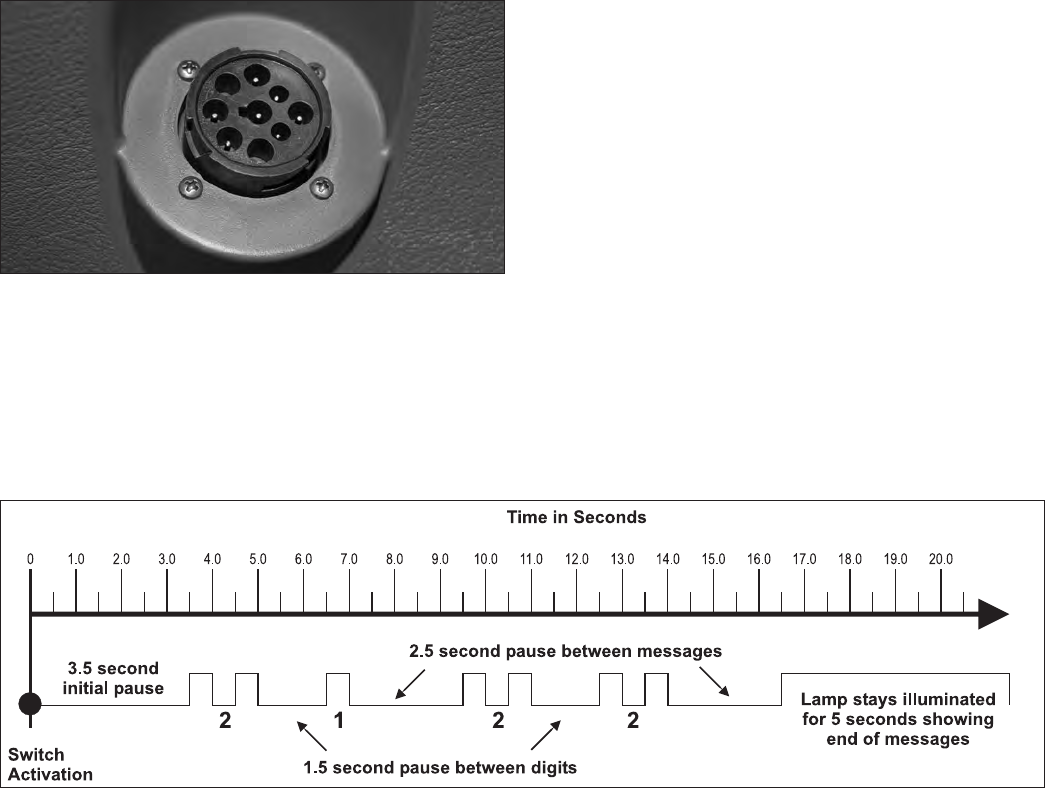
21
BLINK CODES
Blink codes allow a technician to troubleshoot ABS
problems without using a hand‑held or PC‑based
diagnostic tool. Instead, information about the ABS system
is communicated by the Bendix ESP EC‑80 Controller using
the ABS indicator lamp to display sequences of blinks.
Note: The Bendix ESP EC-80 Controller will not enter the
diagnostic blink code mode if the wheel speed sensors
show that the vehicle is in motion. If the ECU is in the
diagnostic blink code mode and then detects vehicle
motion, it will exit the blink code mode.
In addition, by operating the Blink Code Switch as
described below, one of several diagnostic modes can be
entered. See Diagnostic Modes below.
Blink Code Switch Activation
When activating the Blink Code Switch:
1. Wait at least two seconds after “ignition on.” (Except
when entering Reconguration Mode ‑ see System
Reconguration section on page 16.)
2. For the Bendix ESP EC‑80 Controller to recognize that
the switch is activated “on,” the technician must press
for at least 0.1 seconds, but less than ve (5) seconds.
(If the switch is held for more than ve (5) seconds, the
ECU will register a malfunctioning switch.)
3. Pauses between pressing the switch when a sequence
is required, (e.g. when changing mode) must not be
longer than two (2) seconds.
4. After a pause of three‑and‑a‑half (3.5) seconds, the
ECU will begin responding with output information
blinks. See Figure 15 for an example.
ELECTRONIC CONTROL UNIT (ECU)
DIAGNOSTICS
The Bendix® ESP® EC‑80™ Controller contains self‑testing
diagnostic circuitry that continuously checks for the normal
operation of internal components and circuitry, as well as
external ABS components and wiring.
Active Diagnostic Trouble Codes (DTCs)
When an erroneous system condition is detected, the
Bendix ESP EC‑80 Controller:
1. Illuminates the appropriate indicator lamp(s) and
disengages part or all of the Bendix ABS, ATC and
ESP system functions. (See ABS Partial Shutdown,
on page 15.);
2. Places the appropriate DTC information in the Electronic
Control Unit (ECU) memory; and
3. Communicates the appropriate DTC information over
the serial communications diagnostic link as required.
Hand‑held or PC‑based diagnostic tools attach to the
vehicle diagnostic connector, typically located on or
under the dash (see Figure 14).
FIGURE 14 - TYPICAL VEHICLE DIAGNOSTIC
CONNECTOR LOCATIONS (J1939)
Troubleshooting: Blink Codes and Diagnostic Modes
FIGURE 15 - EXAMPLE OF A BLINK CODE MESSAGE

22
Blink Code Timing
The Bendix® ESP® EC‑80™ Controller responds with
a sequence of blink codes. The overall blink code
response from the Electronic Control Unit (ECU) is called
a “message.” Each message includes, depending on the
mode selected by the technician, a sequence of one or
more groups of blinks. Simply record the number of blinks
for each sequence and then use the troubleshooting index
on page 26 for active or inactive Diagnostic Trouble Codes
(DTCs) and you will be directed to the page that provides
troubleshooting information.
NOTE:
1. Sequences of blinks illuminate the ABS indicator lamp
for half a second, with half‑second pauses between
them.
2. Pauses between blink code digits are one‑and‑a‑half
(1.5) seconds.
3. Pauses between blink code messages are two‑and‑a‑
half (2.5) seconds.
4. The lamp remains on for ve (5) seconds at the end of
messages.
Once the ABS indicator lamp begins displaying a sequence
of codes, it continues until all blink code messages have
been displayed and then returns to the normal operating
mode. During this time, the Bendix ESP EC‑80 Controller
will ignore any additional Blink Code Switch activation.
All DTCs, with the exception of voltage and J1939 DTCs,
will remain in an active state for the remainder of the
power cycle.
Voltage DTCs will clear automatically when the voltage
returns within the required limits. All Bendix ABS functions
will be re‑engaged.
J1939 DTCs will clear automatically when communications
are re‑established.
DIAGNOSTIC MODES
In order to communicate with the Bendix ESP EC‑80
Controller, there are several modes that the technician can
select to allow information to be retrieved, or other ECU
functions to be accessed.
Diagnostic Modes
To enter the various diagnostic modes:
No. of
Times to
Press the
Blink Code
Switch
System Mode Entered
1Active Diagnostic Trouble Code (DTC) Retrieval
2Inactive DTC Retrieval
3Clear Active DTCs
4System Conguration Check
5Dynamometer Test
7* Recongure ECU
* To enter the Reconguration Mode, the switch must be held
in before the application of ignition power. Once the power is
supplied, the switch is released and then pressed seven times.
FIGURE 16 - DIAGNOSTIC MODES
Active Diagnostic Trouble Code Mode
For troubleshooting, typically the Active and Inactive
DTC Retrieval Modes are used. The technician presses
the Blink Code Switch once and the ABS indicator lamp
ashes a rst group of two codes, and if there are more
DTCs recorded, this is followed by a second set of codes,
etc. (See page 26 for a directory of these codes.) All
active DTCs may also be retrieved using a hand‑held or
PC‑based diagnostic tool, such as the Bendix® ACom®
Diagnostic Software.
To clear active DTCs (as problems are xed), simply
clear (or “self‑heal”) by removing and re‑applying ignition
power. The only exception is for wheel speed sensor
DTCs, which clear when power is removed, re‑applied, and
the ECU detects valid wheel speed from all wheel speed
sensors. Alternately, codes may be cleared by pressing the
diagnostic Blink Code Switch three (3) times (to enter the
Clear Active Diagnostic Trouble Code Mode) or by using
a hand‑held or PC‑based diagnostic tool. Hand‑held or
PC‑based diagnostic tools are able to clear wheel speed
sensor DTCs without the vehicle being driven.

23
Inactive Diagnostic Trouble Code Mode
The Bendix® ESP® EC‑80™ Controller stores past
Diagnostic Trouble Codes (DTCs) and comments (such
as conguration changes) in its memory. This record is
commonly referred to as “event history.” When an active
DTC is cleared, the Electronic Control Unit (ECU) stores it
in the event history memory as an inactive DTC.
Using blink codes, the technician may review all inactive
DTCs stored on the ECU. The ABS indicator lamp
will display inactive diagnostic blink codes when the
diagnostic Blink Code Switch is depressed and released
two times. See page 26 for the index showing DTCs and
the troubleshooting guide page to read.
Inactive DTCs, and event history, may be retrieved and
cleared by using a hand‑held or PC‑based diagnostic tool,
such as the Bendix® ACom® Diagnostic Software.
Clearing Active DTCs
The ECU will clear active DTCs when the diagnostic Blink
Code Switch is depressed and released three (3) times.
System Conguration Check Mode
The ABS indicator lamp will display system conguration
information when the diagnostic Blink Code Switch is
depressed and released four times. The lamp will blink
out conguration information codes using the following
patterns. (See Figure 17).
In this mode the ECU tells the technician — by means of a
series of seven (7) blink codes — the type of ABS system
that the ECU has been set up to expect. For example, if
the fourth blink code is the number two (2), the technician
knows that a 6S/4M sensor/modulator conguration has
been set.
Dynamometer Test Mode
The Dynamometer Test Mode is used to disable Bendix®
ESP® & ATC system functions when needed (e.g. when
performing any vehicle maintenance where the wheels are
lifted off the ground and moving, including dynamometer
testing). Note: For Bendix ESP and ABS EC‑80
Controllers, this mode will remain engaged even if
power to the ECU is removed and re‑applied. To exit
the Dynamometer Test Mode, press and release the Blink
Code Switch three (3) times, or use a hand‑held or PC‑
based diagnostic tool.
1st Number System Power
112 Volts
2nd
Number
Wheel Speed Sensors
44 Sensors
66 Sensors
3rd Number Pressure Modulator Valves
44 Modulators
55 Modulators
66 Modulators
4th Number ABS Conguration
14S/4M or 6S/6M
26S/4M
36S/5M
5th Number Traction Control Conguration
2No ATC
3ATC Engine Control Only
4ATC Brake Control Only
5Full ATC (Engine Control & Brake Control)
6th Number Retarder Conguration
1No Retarder
2J1939 Retarder
3Retarder Relay
4J1939 Retarder, Retarder Relay
7th Number Stability Conguration
1No Stability Program
2Electronic Stability Program (ESP)
FIGURE 17 - SYSTEM CONFIGURATION CHECK
Recongure ECU Mode
Controller reconfiguration is carried out by using the
Recongure ECU Mode. (See page 16.)
Note: To enter the Reconguration Mode, the Blink Code
Switch must be held in before the application of ignition
power. Once the power is supplied, the switch is released
and then pressed seven times.
Other Methods
Troubleshooting and DTC clearing (as well as recongura‑
tion) may also be carried out using hand‑held or PC‑based
diagnostic tools such as the Bendix® Remote Diagnostic
Unit (RDU™), Bendix ACom Diagnostic Software, or similar
tools.
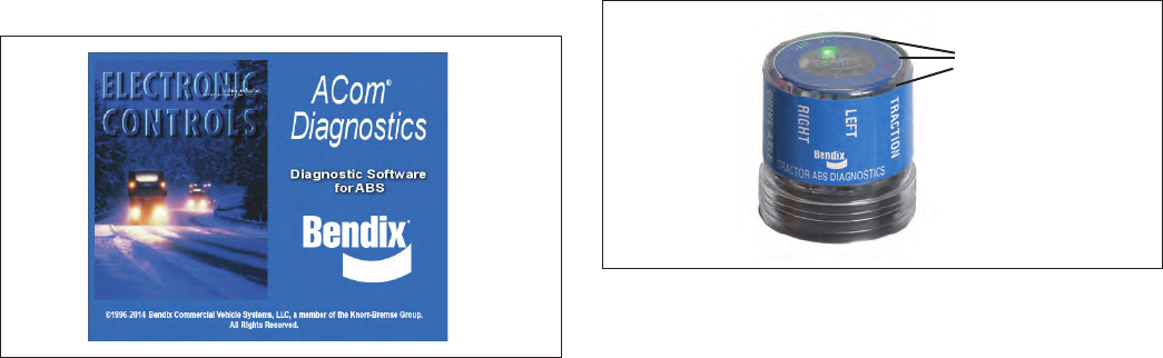
24
Troubleshooting: Using PC-Based or
Hand-Held Diagnostic Tools
BENDIX® ACOM® DIAGNOSTIC SOFTWARE
FIGURE 18 - BENDIX® ACOM® DIAGNOSTICS
Bendix® ACom® Diagnostic Software is a PC‑based
program and is designed to meet RP‑1210 industry
standards developed by the Truck Maintenance Council
(TMC). This software provides the technician with access
to all the available Bendix® EC‑80™ ESP® Controller's
diagnostic information and configuration capability,
including:
• ECU information;
• Diagnostic Trouble Codes (DTCs) and repair
information;
• Conguration (ABS, ATC, and more);
• Wheel speed information;
• Perform component tests; and
• Save and print information
Note: Bendix ACom Diagnostic Software V6.7.2.5 (or
higher) is required to calibrate the Steering Angle
Sensor, the Yaw Rate/Lateral Acceleration Sensor, the
Brake Demand Sensors and the Load Sensor.
When using ACom Diagnostic Software V6.7.2.5 (or
higher) to diagnose the Bendix ESP EC‑80 Controller, the
computer’s serial or parallel port needs to be connected
to the vehicle’s diagnostic connector.
BENDIX® RDU™ (REMOTE DIAGNOSTIC
UNIT)
The Bendix® RDU™ tool (Bendix part number K101596N001)
provides the technician with a visual indication of Antilock
Braking System (ABS) component Diagnostic Trouble
Code (DTC) information. Note: Previous versions of the
RDU tool are not compatible with the Bendix ESP EC-80
Controller. The Bendix RDU tool is specically designed
for use with Bendix® brand ABS systems and Bendix makes
no claims for its operation and/or usability with other brands
of ABS systems.
LED lights
illuminate
Diagnostic
Trouble
Codes
(10 locations
in total)
FIGURE 19 - THE BENDIX® REMOTE DIAGNOSTIC UNIT
Features of the Bendix RDU Tool
The Bendix RDU tool attaches to the 9‑pin diagnostic
connector in the cab of the vehicle.
The Bendix RDU tool allows the technician to:
• Troubleshoot ABS system component problems using
DTC reporting via LEDs;
• Reset DTCs on Bendix ESP EC‑80 Controllers by
holding a magnet over the reset in the center of the RDU
tool for less than six (6) seconds; and
• Enter the Self‑Conguration Mode used by Bendix ESP
EC‑80 Controllers by holding a magnet over the reset
area for greater than six (6) seconds but less than 30
seconds.
How the Bendix RDU Operates
See Figure 14 for typical vehicle connector locations.
When the Bendix RDU tool is plugged into the diagnostic
connector, all the LEDs will illuminate, and the green LED
will ash four (4) times to indicate communications have
been established.
If the Bendix ESP EC‑80 Controller has no active DTCs,
only the green LED will remain illuminated.
If the Bendix ESP EC‑80 Controller has at least one active
DTC, the RDU tool displays the rst DTC by illuminating the
red LEDs, indicating the malfunctioning ABS component
and its location on the vehicle (See Figure 20.) If there
are multiple DTCs on the ABS system, the RDU tool will
display one DTC rst, then — once that DTC has been
repaired and cleared — the next code will be displayed.

25
Typical Combination
Diagnostic Trouble Codes (DTCs) are:
• Right steer sensor
• Left steer sensor
• Right drive sensor
• Left drive sensor
• Right additional sensor
• Left additional sensor
• Right steer modulator
• Left steer modulator
• Right drive modulator
• Left drive modulator
• Right additional
modulator
• Left additional modulator
• Rear Axle Traction
modulator
• ECU
• Engine serial
communication
• MOD red LED illuminated, shows the "Common"
connection of one or more modulators is shorted to
battery or ground
• VLT (Flashing indicates either over‑ or under‑voltage
condition)
To pinpoint the root cause and to ensure the system
Diagnostic Trouble Code is properly corrected the rst time,
additional troubleshooting may be necessary.
Note: The Bendix® RDU™ tool is not capable of diagnosing
certain Bendix® ESP® EC-80™ system-specific DTCs
including additional sensors: steering angle sensors, yaw
sensors, pressure sensors, or modulator valves (trailer
pressure modulating valves or front axle traction control
valves.)
LED DIAGNOSTIC TROUBLE CODES
LFT ‑ Left
RHT ‑ Right
DRV ‑ Drive Axle
ADD ‑ Additional
STR ‑ Steer Axle
VLT ‑ Power
ECU ‑ ABS Controller
SEN ‑ Wheel Speed
Sensor
MOD ‑ Pressure Modulator
Valve
TRC ‑ Traction Control
Example: If the
Diagnostic Trouble Code
is "Right Steer Axle
Sensor", the Bendix RDU
tool will display one green
and three red LEDs
LEDs
Green
VLT
Red
SEN
STR
RHT
FIGURE 20 - DIAGNOSTIC TROUBLE CODES AS
DISPLAYED ON THE BENDIX® RDU™ TOOL
Bendix® RDU™ Reset Function
The magnetic reset switch is located in the center top of
the Bendix RDU tool. Activation requires a magnet with
30 gauss minimum.
The reset operations are:
1. If the magnet is held over the switch for less than 6
seconds the "clear current DTCs" command is sent.
2. If the magnet is held over the switch for more than 6
seconds, but less than 30 seconds, the Bendix ABS
"self‑conguration command" is sent.
Additionally, it is recommended at the end of any inspection
that the user switches off and restores the power to
the Bendix ESP EC‑80 Controller, then check the ABS
Indicator Lamp operation and Bendix RDU tool to see if
they indicate any remaining DTCs.
Bendix RDU Communication Problems
If the Bendix ESP EC‑80 Controller does not respond to the
RDU tool’s request for DTCs, the RDU tool will illuminate
each red LED in a clockwise pattern. This pattern indicates
the loss of communication and will continue until the Bendix
ESP EC‑80 Controller responds and communication has
been established.
Possible sources of communication problems are:
1. A problem with the J1939 link at the in‑cab off‑board
diagnostic connector (9 or 6 Pin);
2. The Bendix ESP EC‑80 Controller does not support
PID194;
3. No power is being supplied to the Bendix ESP EC‑80
Controller and/or the diagnostic connector;
4. The J1939 bus is overloaded with information and the
RDU can not arbitrate access; or
5. A malfunctioning Bendix RDU tool.
Other Information
For more information on Bendix® ACom® Diagnostics
Software or RP‑1210 compliant tools, go to www.bendix.
com or visit your local authorized Bendix distributor.
See pages 56-62 for Appendices showing J1939 SID, FMI,
codes and their Bendix blink code equivalents.
www.bendix.com
For the latest information, and for free downloads of
the Bendix® ACom® Diagnostic Software, and its User
Guide, visit the Bendix website at www.bendix.com.
Bendix Technical Assistance Team
For direct telephone technical support, call the Bendix
technical assistance team at:
1-800-AIR-BRAKE (1‑800‑247‑2725 option 2, then 1),
Monday through Friday, 8:00 a.m. to 6:00 p.m. ET,
and follow the instructions in the recorded message.
E‑mail the Bendix Technical Assistance Team at:
techteam@bendix.com.

26
Active or Inactive Diagnostic Trouble Codes (DTCs):
INDEX
How to interpret the first digit of messages received
when Active or Inactive Diagnostic Trouble Code Mode
is entered.
1st
Blink
Code
Number
1 ............................... No DTCs (1,1)
2 ............. Wheel Speed Sensors ‑ pages 27‑28
3 ............. Wheel Speed Sensors ‑ pages 27‑28
4 ............. Wheel Speed Sensors ‑ pages 27‑28
5 ............. Wheel Speed Sensors ‑ pages 27‑28
6 ........................Power Supply ‑ page 29
7 ..........Pressure Modulator Valves ‑ pages 30‑31
8 ..........Pressure Modulator Valves ‑ pages 30‑31
9 ..........Pressure Modulator Valves ‑ pages 30‑31
10 .........Pressure Modulator Valves ‑ pages 30‑31
11 ..........................J1939 ‑ pages 32‑33
12 ...................Miscellaneous ‑ pages 34‑35
13 ..............................ECU ‑ page 36
14 ............ Wheel Speed Sensors ‑ pages 27‑28
15 ............ Wheel Speed Sensors ‑ pages 27‑28
16 .........Pressure Modulator Valves ‑ pages 30‑31
17 .........Pressure Modulator Valves ‑ pages 30‑31
18 ....... Drive Axle Traction Control Valve ‑ page 37
19 .......Steer Axle Traction Control Valve ‑ page 37
20 ....Trailer Pressure Modulator Valve ‑ pages 30‑31
21 ............Steering Angle Sensor ‑ pages 38‑39
22 ................ Yaw Rate Sensor ‑ pages 40‑41
23 ............Lateral Acceleration Sensor ‑ page 42
24 ..........Brake Demand/Load Sensors ‑ page 43
25 .................Valves Miscellaneous ‑ page 44
26 ............... J1939 ESP‑Related ‑ page 45‑47
Example: For a message sequence of:
3, 2 12, 4
For the rst sequence go to page 27 and
for the second sequence go to page 34.
Troubleshooting Tests
See Page 56-62 for APPENDIX B: J1939 SPN and FMI Codes and their Bendix Blink Code Equivalents
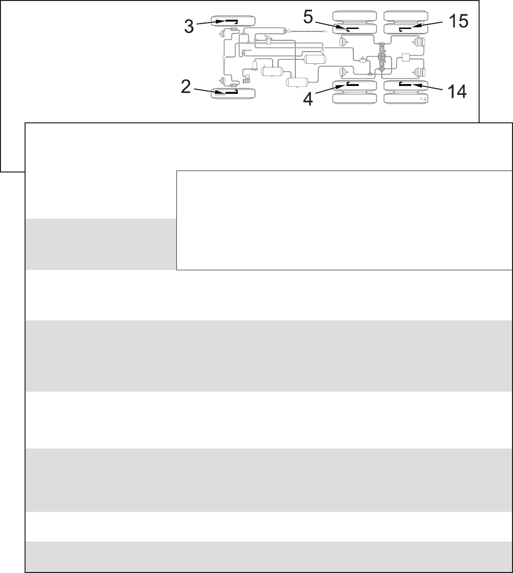
27
Troubleshooting Diagnostic Trouble Codes (DTCs):
Wheel Speed Sensors
2 Left Steer Axle Sensor
3 Right Steer Axle Sensor
4 Left Drive Axle Sensor
5 Right Drive Axle Sensor
14 Left Additional Axle Sensor
15 Right Additional Axle Sensor
1st. Blink
Code Location
2nd.
Blink
Code
Diagnostic Trouble
Code Description Repair Information
1 Excessive Air Gap
Adjust the sensor to contact the exciter ring. Rotate the wheel and verify a minimum
of 0.25 VAC sensor output at ~ 0.5 RPS. Verify the condition of the sensor head.
Verify the mounting of the exciter ring and condition of the teeth. Verify the proper
bearing end‑play. Verify the condition and retention of the clamping sleeve. Verify
the sensor lead routing and clamping.
2 Output Low at
Drive‑off
3Open or Shorted Verify 1500 – 2500 ohms is found across the sensor leads. Verify no continuity between
the sensor leads and ground or voltage. Verify no continuity between the sensor leads
and the other sensors. Check for corroded/damaged wiring or connectors between
the Electronic Control Unit (ECU) and the wheel speed sensor.
4 Loss of Sensor Signal Adjust the sensor to contact the exciter ring. Rotate the wheel and verify a minimum
of 0.25 VAC sensor output at ~ 0.5 RPS. Verify the condition of sensor head. Verify
the mounting of the exciter ring and condition of the teeth. Verify the proper bearing
end‑play. Verify the condition and retention of the clamping sleeve. Verify the sensor
lead routing and clamping. Check for corroded/damaged wiring or connectors between
the ECU and the wheel speed sensor.
5Wheel End Verify the mounting of exciter ring and the condition of teeth. Verify the proper bearing
end‑play. Verify the condition and retention of the clamping sleeve. Verify the sensor
lead routing and clamping. Check the mechanical function of brake. Check for kinked
or restricted air hoses.
6 Erratic Sensor Signal Adjust the sensor to contact the exciter ring. Rotate the wheel and verify a minimum
of 0.25 VAC sensor output at ~ 0.5 RPS. Verify the condition of sensor head. Verify
the mounting of the exciter ring and condition of the teeth. Verify the proper bearing
end‑play. Verify the condition and retention of the clamping sleeve. Verify the sensor
lead routing and clamping. Check for corroded/damaged wiring or connectors between
the ECU and the wheel speed sensor.
7 Tire Size Calibration Verify the correct tire size as desired. Verify the proper tire ination. Verify the correct
number of exciter ring teeth.
10 Conguration Error The ECU is congured for four sensors, but it has detected the presence of additional
sensors. Verify the sensor wiring and the ECU conguration.
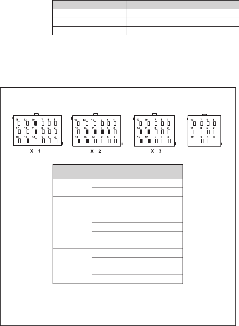
28
Cab-mount ECU: Looking into
the wire harness connector
X4
Connector Pin Wheel Speed Sensor
Location
X1
18 Way
10 Right Drive Axle (+)
11 Right Drive Axle (‑)
X2
18 Way
5 Left Steer Axle (+)
8Left Steer Axle (‑)
11 Right Steer Axle (+)
14 Right Steer Axle (‑)
15 Left Drive Axle (+)
18 Left Drive Axle (‑)
X3
15 Way
(if ECU is
congured for
6 sensors)
11 Left Additional Axle (+)
14 Left Additional Axle (‑)
12 Right Additional Axle (+)
15 Right Additional Axle (‑)
Speed Sensor Repair Tests:
1. Take all measurements at the Electronic Control Unit
(ECU) harness connector pins in order to the check wire
harness and sensor. Probe the connector carefully so
that the terminals are not damaged.
2. The wheel speed sensor measurements should read:
Location Measurement
Sensor 1500 ‑ 2500 Ohms
Sensor to voltage or ground Open Circuit (no continuity)
Sensor output voltage >0.25 of VAC sensor output at ~ 0.5 revs/sec.
3. Clear the DTC after the issue is corrected. The sensor
DTC will remain until the power is cycled to the ABS
ECU and vehicle is driven above 15 MPH or the DTC
was cleared using either the diagnostic Blink Code
Switch or a diagnostic tool.
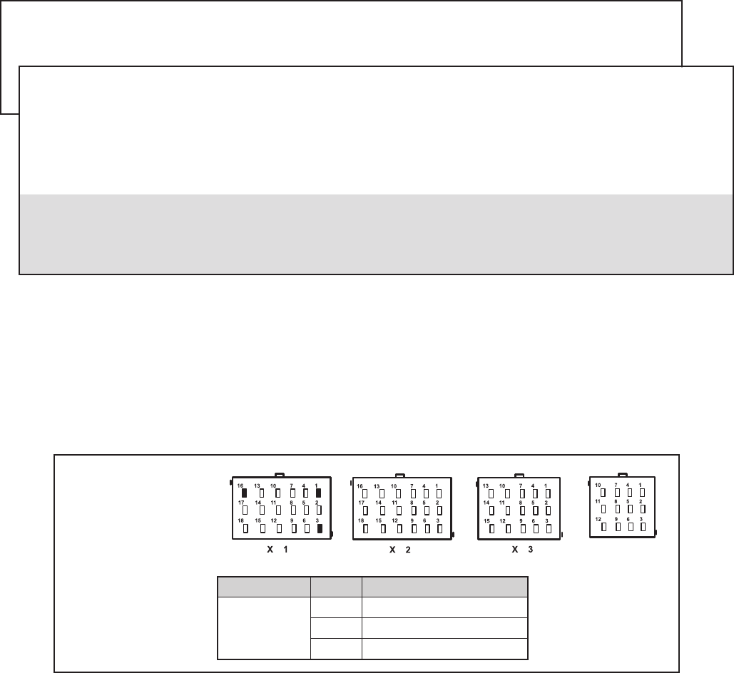
29
Connector Pin Power Supply Test
X1
18 Way
1Ground
2Ignition
16 Battery
Troubleshooting Diagnostic Trouble Codes (DTCs): Power Supply
6 Power Supply
1st. Blink
Code Location
Power Supply Tests:
1. Take all measurements at the ECU harness
connector.
2. Place a load (e.g. an 1157 stop lamp) across the
battery or ignition and ground connection, measure
the ignition and battery voltage with the load. Ignition
to Ground should measure between 9 to 17 VDC.
Battery to Ground should also measure between 9 to
17 VDC.
Cab-mount ECU:
Looking into wire
harness connector
3. Check for damaged wiring, damaged or corroded
connectors and connections.
4. Check the condition of the vehicle battery and
associated components, verify that the ground
connection is good and tightened.
5. Check the alternator output for excessive noise.
X4
2nd.
Blink
Code
Diagnostic Trouble
Code Description Repair Information
1Battery Voltage Too
Low Measure the battery voltage under load. Check the vehicle battery and associated
components. Check for damaged wiring. Check for damaged or corroded connectors
and connections.
2Battery Voltage Too
High Measure the battery voltage under load. Ensure that battery voltage is correct
for the Electronic Control Unit (ECU). Check the vehicle battery and associated
components. Check for damaged wiring. Check for damaged or corroded connectors
and connections.

30
Troubleshooting Diagnostic Trouble Codes (DTCs):
Pressure Modulator Valves (PMVs)
7 Left Steer Axle
8 Right Steer Axle
9 Left Drive Axle
10 Right Drive Axle
16 Left Additional Axle
17 Right Additional Axle
20 Trailer PMV
1st. Blink
Code Location
2nd.
Blink
Code
Diagnostic Trouble
Code Description Repair Information
1Release Solenoid
Shorted to Ground Verify no continuity between the PMV leads and ground. Verify 4.9 to 5.5 ohms
from REL to CMN & HLD to CMN, and 9.8 to 11 ohms from REL to HLD. Check
for corroded/damaged wiring or connectors between the Electronic Control Unit
(ECU) and PMV.
2Release Solenoid
Shorted to Voltage Verify no continuity between the PMV leads and voltage. Verify 4.9 to 5.5 ohms
from REL to CMN & HLD to CMN, and 9.8 to 11 ohms from REL to HLD. Check
for corroded/damaged wiring or connectors between the ECU and PMV.
3Release Solenoid
Open Circuit Verify 4.9 to 5.5 ohms from REL to CMN & HLD to CMN, and 9.8 to 11 ohms from
REL to HLD. Check for corroded/damaged wiring or connectors between the
ECU and PMV.
4Hold Solenoid Shorted
to Ground Verify no continuity between the PMV leads and ground. Verify 4.9 to 5.5 ohms
from REL to CMN & HLD to CMN, and 9.8 to 11 ohms from REL to HLD. Check
for corroded/damaged wiring or connectors between the ECU and PMV.
5Hold Solenoid Shorted
to Voltage Verify no continuity between the PMV leads and voltage. Verify 4.9 to 5.5 ohms
from REL to CMN & HLD CMN, and 9.8 to 11 ohms from REL to HLD. Check for
corroded/damaged wiring or connectors between the ECU and PMV.
6Hold Solenoid Shorted
to Open Circuit Verify 4.9 to 5.5 ohms from REL to CMN & HLD to CMN, and 9.8 to 11 ohms from
REL to HLD. Check for corroded/damaged wiring or connectors between the
ECU and PMV.
7CMN Open Circuit Verify 4.9 to 5.5 ohms from REL to CMN & HLD to CMN, and 9.8 to 11 ohms from
REL to HLD. Check for corroded/damaged wiring or connectors between the ECU
and PMV. This is potentially a miswired or internal mechanical problem.
8Conguration Error A mis‑match exists between the ECU conguration and the modulator installation
and wiring. Verify the PMV wiring and installation. Verify the ECU conguration.
Special Note regarding Trailer PMV: Pneumatic issues can result in this DTC being
set. Verify all lines are free from debris or other obstructions, kinks, etc.
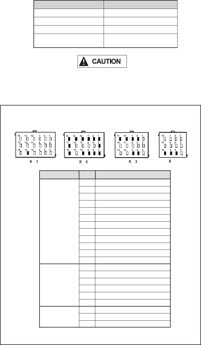
31
Pressure Modulator Valve (PMV) Repair Tests:
1. Take all measurements at the Electronic Control Unit (ECU) harness
connector pins in order to check wire harness and PMV. Probe the
connector carefully so that the terminals are not damaged.
2. The pressure modulator resistance should read:
Location Measurement
Release to Common 4.9 to 5.5 Ohms
Hold to Common 4.9 to 5.5 Ohms
Release to Hold 9.8 to 11.0 Ohms
Release, Hold, Common to
Voltage or Ground Open Circuit (no continuity)
When troubleshooting modulator Diagnostic Trouble Codes (DTCs),
check inactive DTCs and the event history for over-voltage or
excessive noise DTCs. If one of these is found, troubleshoot these
DTCs rst before the PMV.
Cab-mount ECU: Looking into
the wire harness connector
4
Connector Pin PMV Location
X2
18 Way
1 Left Steer Axle Hold
2 Left Steer Axle Release
3 Left Steer Axle Common
4 Right Steer Axle Hold
6 Right Steer Axle Common
7 Right Steer Axle Release
9 Right Drive Axle Common
10 Right Drive Axle Hold
13 Right Drive Axle Release
12 Left Drive Axle Common
16 Left Drive Axle Hold
17 Left Drive Axle Release
X3
15 Way (if
the ECU is
congured for
6 modulators)
4 Left Additional Axle Hold
6 Left Additional Axle Common
7 Left Additional Axle Release
9 Right Additional Axle Common
10 Right Additional Axle Hold
13 Right Additional Axle Release
X4
12 Way
6 Trailer PMV Hold
9Trailer PMV Release
12 Trailer PMV Common

32
1st. Blink
Code
11
Location:
J1939
Troubleshooting Diagnostic Trouble Codes (DTCs):
J1939 Serial Communications
2nd.
Blink
Code
Diagnostic Trouble
Code Description Repair Information
1 J1939 Serial Link There is loss of communications between the Bendix® ESP® EC‑80™ Controller and
other devices connected to the J1939 link. Check for damaged or reversed J1939
wiring. Check for corroded or damaged connectors. Verify the Electronic Control
Unit (ECU) conguration. Check for other devices inhibiting J1939 communications.
2J1939 Electronic
Retarder Time‑out
or Invalid Signal
Check for damaged or reversed J1939 wiring. Check for corroded or damaged
connectors. Verify the presence of a retarder on the J1939 link. Verify the ECU
conguration. Verify that the retarder is congured to broadcast ERC1. Check for
other devices inhibiting J1939 communications.
3J1939 Electronic Engine
Controller 1 Time‑out
or Invalid Signal
Check for damaged or reversed J1939 wiring. Check for corroded or damaged
connectors. Verify the presence of ECU on the J1939 link. Verify the ECU
conguration. Verify the ECU is congured to broadcast EEC1. Check for other
devices inhibiting J1939 communications.
4J1939 Electronic Engine
Controller 2 Time‑out
or Invalid Signal
Check for damaged or reversed J1939 wiring. Check for corroded or damaged
connectors. Verify the presence of Engine ECU on the J1939 link. Verify the ECU
conguration. Verify that there is an EEC2 broadcast from the address congured
in the ABS ECU. Check for other devices inhibiting J1939 communications.
5 J1939 AIR Message
Time‑out or Invalid
Signal
Invalid pressure signals received from a vehicle Controller. Verify the proper
operation of brake demand sensors. Check wiring between brake demand sensors
and the vehicle Controller. Verify the proper programming of vehicle Controller.
Check for damaged or reversed J1939 wiring. Check for damaged or corroded
connectors. Check for other device inhibiting J1939 communications.
6 ESP J1939 CAN
Message Time‑out
Invalid ESP messages on the J1939 link. Check for damaged or reversed J1939
wiring. Check for damaged or corroded connectors. Verify the presence of engine
and / or retarder on J1939. Verify the proper programming of engine and/or retarder.
Check for other devices inhibiting J1939 communications.
7J1939 Transmission
Communication for HSA
There is loss of communications between the EC‑80 ECU and the transmission
ECU over the J1939 link. Check for damaged or reversed J1939 wiring. Check
for damaged or corroded connectors. Verify the presence of transmission ECU on
J1939 link. Check for other devices inhibiting J1939 communications.
8 Time‑out or invalid data
on XBR
Check for damaged or reversed J1939 wiring. Check for damaged or corroded
connectors. Check for other devices inhibiting J1939 communications. Verify the
ECU conguration. Verify XBR message being broadcast from address 42.
10 J1939 Electronic
Transmission Controller
1 Time‑out or Invalid
Signal
There is loss of communications between the Bendix EC‑80 Controller and the
transmission ECU over the J1939 link. Check for damaged or reversed J1939 wiring.
Check for corroded or damaged connectors. Verify the presence of engine ECU
on the J1939 link. Verify the ECU conguration. Check for other devices inhibiting
J1939 communications.
11 AUXIO CAN message
Time‑out
Check for damaged or reversed J1939 wiring. Check for damaged or corroded
connectors. Check for other devices inhibiting J1939 communications. Verify the
ECU conguration. Verif y AUX IO broadc ast from address c ongured in EC‑ 80 ECU.
12 J1939 Hill Start Feature
Switch Signal Not
Available
Check for damaged or reversed J1939 wiring. Check for damaged or corroded
connectors. Verif y the ECU conguration. Verify EBC1 being broadcast with a valid
SPN 577 parameter. Check for other devices inhibiting J1939 communications.
14 J1939 CAN Message
related to ESP is
incomplete
Check for damaged or reversed J1939 wiring. Check for damaged or corroded
connectors. Check for other devices inhibiting J1939 communications. Verify the
ECU conguration. Verify ESP messages.

33
Cab-mount ECU:
Looking into wire harness connector
J1939 Troubleshooting Tests:
1. Take all measurements at ECU harness
connector.
2. Check for damaged or reversed J1939
wiring.
3. Check for corroded or damaged wiring
connector problems such as (opens or
shorts to voltage or ground).
4. Check for other J1939 devices which
may be loading down (inhibiting) J1939
communication.
X4
2nd.
Blink
Code
Diagnostic Trouble
Code Description Repair Information
15 J1939 Electronic Engine
Controller 3 Time‑out or
Invalid Signal
There is loss of communications between the Bendix® ESP® EC‑80™ Controller and
the engine Electronic Control Unit (ECU) over the J1939 link. Check for damaged
or reversed J1939 wiring. Check for corroded or damaged connectors. Verify the
presence of engine ECU on the J1939 link. Verify the ECU conguration. Check
for other devices inhibiting J1939 communications.
16 J1939 Electronic
Transmission Controller
2 Time‑out
There is loss of communications between the Bendix EC‑80 Controller and the
transmission ECU over the J1939 link. Check for damaged or reversed J1939 wiring.
Check for corroded or damaged connectors. Verify the presence of engine ECU
on the J1939 link. Verify the ECU conguration. Check for other devices inhibiting
J1939 communications..
20 J1939 EAC1 Time‑out
or Invalid Signal
Verify 60 ohms of resistance between X1 pin 7 and X1 pin 8. Check for damaged
or reversed J1939 wiring. Check for damaged or corroded connectors. Verify that
the message is being transmitted. Verify data for Electronic Axle Controller 1 is
correct. Verify the ECU conguration.
21 CAN Message
CGW_C1 Time‑out or
invalid signal
Verify 60 ohms of resistance between X1 pin 7 and X1 pin 8. Check for damaged or
reversed J1939 wiring. Check for damaged or corroded connectors. Verify that the
message is being transmitted. Verify that the data for differential lock(s) is correct.
Verify the ECU conguration.
22 CAN Message
ASC1_CLCS Time‑out
or invalid signal
Verify 60 ohms of resistance between X1 pin 7 and X1 pin 8. Check for damaged
or reversed J1939 wiring. Check for damaged or corroded connectors. Verify that
the message is being transmitted. Verify that the data for Air Suspension Control 1
is correct. Verify the ECU conguration.
23 J1939 CCVS Time‑out
or Invalid Signal
Verify 60 ohms of resistance between X1 pin 7 and X1 pin 8. Check for damaged or
reversed J1939 wiring. Check for damaged or corroded connectors. Verify message
is being transmitted. Verify the ECU conguration.
24 J1939 TCO
(Tachograph)
Time‑out
Verify 60 ohms of resistance between X1 pin 7 and X1 pin 8. Check for damaged or
reversed J1939 wiring. Check for damaged or corroded connectors. Verify message
is being transmitted. Verify the ECU conguration.
26 J1939 Address Conict
ABS Address
Verify only one ABS ECU is connected on J1939 bus, broadcasting OBh (equals
13 decimal).
27 J1939 Address Conict
TPMS Address
Verify only one TPMS ECU is connected on J1939 bus, broadcasting 33h.
28 J1939 Proprietary XBR
Message Out of Range
Verify 60 ohms of resistance between X1 pin 7 and X1 pin 8. Check for damaged
or reversed J1939 wiring. Check for damaged or corroded connectors. Check for
messages being transmitted/received.
29 J1939 CAN Messages
Are Not Being
Transmitted/Received
Verify 60 ohms of resistance between X1 pin 7 and X1 pin 8. Check for damaged
or reversed J1939 wiring. Check for damaged or corroded connectors. Check for
messages being transmitted/received.
Connector Pin J1939
X1
18 Way
7J1939 Low
8J1939 High

34
1st. Blink
Code 12 Location:
Miscellaneous
Troubleshooting Diagnostic Trouble Codes (DTCs): Miscellaneous
2nd.
Blink
Code
Diagnostic Trouble
Code Description Repair Information
1Stop Lamp Switch
Not Detected The Electronic Control Unit (ECU) has not detected the presence of the stop lamp switch
since ignition power was applied (note that stop lamp switch input may be applied to
the Bendix® ESP® EC‑80™ Controller using either hard‑wire input or J1939). Apply
and release service brake. Check for brake switch input into ECU (see system wiring
schematic). With service brake released, check for presence of the stop lamp bulb.
With service brake applied, verify system voltage is now present at the stop lamp switch
input to the ECU. Check for damaged wiring between ECU, stop lamp switch and bulb.
Check for corroded or damaged connectors. Check for damaged or reversed J1939
wiring. Check for corroded or damaged connectors on J1939 link. Verify the presence
of engine ECU on the J1939 link. Verify the ECU conguration.
2Stop Lamp Switch
Defective Apply and release service brake. Check for brake switch input into ECU (see system
wiring schematic). With service brake released, check for presence of the stop lamp bulb.
With service brake applied, verify system voltage is now present at the stop lamp switch
input to the ECU. Check for damaged wiring between ECU, stop lamp switch and bulb.
Check for corroded or damaged connectors. Check for damaged or reversed J1939
wiring. Check for corroded or damaged connectors on J1939 link. Verify the presence
of engine ECU on the J1939 link. Verify the ECU conguration.
3ATC or ESP Disabled
or Dynamometer Test
Mode Active
ATC or ESP is disabled. ECU has been placed in the Dynamometer Test Mode by either
the diagnostic Blink Code Switch or a hand‑held or PC‑based diagnostic tool. Clear
DTCs to exit Dynamometer Test Mode.
4Retarder Relay Open
Circuit or Shorted to
Ground
Verify vehicle contains a retarder relay. Verify the ECU conguration. Check wiring
between ECU and retarder relay. Verify no continuity between retarder disable output of
Bendix ESP EC‑80 Controller and ground. Verify condition and wiring of the retarder relay.
5Retarder Relay Circuit
Shorted to Voltage Check wiring between ECU and retarder relay. Verify no continuity between retarder
disable output of Bendix ESP EC‑80 Controller and voltage. Verify condition and wiring
of the retarder relay.
6ABS Indicator Lamp
Circuit DTC Check operation of diagnostic Blink Code Switch. Check wiring of diagnostic Blink Code
Switch (verify ABS wire is not grounded where used) and ABS Indicator Lamp. Verify
ABS Indicator Lamp ground input. On some vehicles with multi‑plex dashes, the ground
wire may not be present - see ECU 19 DTC.
7PMV Common
Shorted to Ground Verify no continuity between the Release, Hold and CMN of all Pressure Modulator Valves
(PMVs), Traction Control Valve (TCV), HSA, Diff Lock Solenoid and ground. Check for
corroded/damaged wiring or connectors between the ECU and CMN of all PMVs, TCV,
and Diff Lock Solenoid. See the extended troubleshooting for this code in Appendix A.
8PMV Common
Shorted to Voltage Verify no continuity between the Release, Hold and CMN of all PMVs, TCV, HSA, Diff
Lock Solenoid and voltage. Check for corroded/damaged wiring or connectors between
the ECU and CMN of all PMVs, TCV, and Diff Lock Solenoid.
9ATC Disabled to
Prevent Brake Fade The Bendix® ATC (Automatic Traction Control) system is temporarily disabled to
prevent excessive heating of the foundation brakes.
11 Wheel Speed
Sensors Reversed on
an Axle
Sensors are reversed (left to right) on one of the axles. Verify the proper installation,
connection, and wiring of the sensors.
14 Sensor CAN Supply
Voltage Error Incorrect supply voltage for the Steering Angle Sensor (SAS) and the Yaw Rate sensor.
Verify the proper voltage at the sensor connectors. Verify the wiring between the ECU
and the sensors. Verify the proper output voltage from ECU. Note: When checking for
voltage at YAW/LAS & SAS, the voltage will only be present momentarily at key ON.
17 ABS disabled due to
off‑road mode The ABS indicator lamp will be ashing, indicating the ECU is in the off‑road ABS mode.
Remove and re‑apply ignition power.
19 Maximum number
of PMV cycles
exceeded Replace all PMV valves and clear the DTC.

35
2nd.
Blink
Code
Diagnostic Trouble
Code Description Repair Information
20 Maximum Number
of TCV Cycles
Exceeded
Replace all Traction Control Valve (TCV) valves and clear the Diagnostic Trouble Code
(DTC).
22 ESP Sensor Voltage
Out of Range Incorrect supply voltage is detected for the Bendix® SAS‑60™ and the Yaw Rate sensor.
Verify the proper voltage at sensor connectors. Verify wiring between the Electronic
Control Unit (ECU) and the sensors. Verify the proper output voltage from ECU.
Note: When checking for voltage at YAW/LAS & SAS, the voltage will only be present
momentarily at key ON.
24 HS Feature Lamp
Open or Shorted
to Ground
Verify no continuity between the Hill Start / Hill Start Assist lamp and ground. Verify
continuity between the lamp and the ECU. Check the wiring between the lamp and the
ECU. Check the lamp and the condition of its wiring.
25 HS Feature Solenoid
Open or Shorted
to Ground
The Hill Start / Hill Start Assist solenoid is shorted to ground or has a broken wire. Verify
no continuity between the solenoid and ground. Check for corroded/damaged wiring or
connectors between the ECU and the solenoid.
26 HS Feature Solenoid
Shorted to Voltage Verify no continuity between the Hill Start / Hill Start Assist Solenoid and voltage. Check
for corroded/damaged wiring or connectors between the ECU and Solenoid.
27 Brake Lamp Input
Mismatch With Brake
Lamp Output There is a brake lamp input mismatch with the brake lamp output.
28 Air system/
Mechanical
Component
Verify brakes are operating correctly. Verify that there is not over‑braking at one or more
wheel end(s). Check the pneumatic plumbing and the exhaust port of the PCVs, TCVs,
and relay valves and conrm that the air is being exhausted from all brake chambers.
Verify tire sizes on the vehicle match the ABS ECU conguration. Verify wheel speed
sensors and tone ring are properly adjusted and in good condition.
29 Air system/
Mechanical
Component
Verify that the tires are in good condition. Verify that no pneumatic hoses are twisted
or kinked. Verify that the brakes are operating correctly. Verify that the wheel speed
sensor and tone ring are properly adjusted. Verify tire size.
30 ESP Disabled due to
Off Road Mode Electronic Stability has been disabled due to the vehicle being in the ABS or ATC off
road mode. Cycle ABS Off Road or ATC Mud snow switch.
31 HS Feature Lamp
Shorted to Voltage Verify that there is no resistance measured between the battery and HSA lamp output
of the ECU. Check the wiring between the ECU and the Hill Start / Hill Start Assist
lamp. Check the lamp and condition of its wiring.
32 I/O 2 or 3 Shorted
High (EC‑80‑ATC)
OR
I/O 2 or 3 shorted
High or Stop Lamp
Output error (ESP
EC‑80)
Check for a short‑circuit condition between voltage and the I/O 2 and I/O 3 circuits.
33 HS Feature Solenoid
Open Circuit Verify resistance across the Hill Start / Hill Start Assist solenoid. Check the ECU and
HSA solenoid for corroded or damaged wiring and/or connectors.
34 eTrac Valve Solenoid
Shorted to Voltage Verify the resistance between voltage and the Bendix® eTrac™ solenoid is open. Check
for corroded or damaged wiring or connectors between the ECU and the eTrac solenoid.
35 eTrac Valve Solenoid
Shorted to Ground Verify the resistance between ground and the Bendix eTrac solenoid is open. Check for
corroded or damaged wiring or connectors between the ECU and the eTrac solenoid.
36 Reserved Reserved
38 Invalid ABS Warning
Lamp Conguration Check X1‑12 if pin/wire installed. X2‑12 should have no terminal or connection. ABS
Warning Lamp is controlled via J1939.

36
1st. Blink
Code
13
Location:
ECU
Troubleshooting Diagnostic Trouble Codes (DTCs): ECU
2nd
Blink
Code
Diagnostic
Trouble Code
Description
(With HEX
designation)
Repair Information
1ECU DTC (5FC)
Check for damaged or corroded connectors. Check for damaged
wiring. Clear Diagnostic Trouble Codes (DTCs). If DTCs return,
contact the Bendix Tech Team at 1‑800‑AIR‑BRAKE (1‑800‑247‑2725,
option 2, then 1) for further troubleshooting assistance.
2ECU DTC (5CD)
3ECU DTC (10)
4ECU DTC (2678C)
5ECU DTC (1C)
6ECU DTC (6CD)
7Conguration
mismatch Verify components installed match the Electronic Control Unit (ECU)
conguration.
8ECU DTC (56)
Check for damaged or corroded connectors. Check for damaged
wiring. Clear DTCs. If DTCs return, contact the Bendix Tech Team
at 1‑800‑AIR‑BRAKE (1‑800‑247‑2725, option 2, then 1) for further
troubleshooting assistance.
9ECU DTC (CAC3)
10 ECU DTC (5F3)
11 ECU DTC (F1A)
12 ECU DTC (F14)
13 Conguration
mismatch Verify components installed match ECU conguration.
14 ECU DTC (C6) Check for damaged or corroded connectors. Check for damaged
wiring. Clear DTCs. If DTCs return, contact the Bendix Tech Team
at 1‑800‑AIR‑BRAKE (1‑800‑247‑2725, option 2, then 1) for further
troubleshooting assistance.
15 ECU DTC (CF)
16 ECU DTC (C0)
17 ECU DTC (C8C)
18 ECU DTC (CC) Parameter le was not downloaded. To verify that the vehicle specic
parameters have been loaded, contact Bendix for more information
at 1‑800‑AIR‑BRAKE (1‑800‑247‑2725).
19 ECU DTC (63)
Check for damaged or corroded connectors. Check for damaged
wiring. Clear DTCs. If DTCs return, contact the Bendix Tech Team
at 1‑800‑AIR‑BRAKE (1‑800‑247‑2725, option 2, then 1) for further
troubleshooting assistance.
20 ECU DTC (6E)
21 ECU DTC (6C)
22 ECU DTC (63C)
25 ECU Internal VIN
Mismatch
The ECU internally‑stored VIN does not match the VIN of the vehicle.
Ensure that the ECU is installed on the correct vehicle. Verify the
ECU programming. Verify engine programming.
26 Valve Conguration
Mismatch
Check for damaged or corroded connectors. Check for damaged
wiring. Clear DTCs. If DTCs return, contact the Bendix Tech Team
at 1‑800‑AIR‑BRAKE (1‑800‑247‑2725, option 2, then 1) for further
troubleshooting assistance.
28 ECU DTC (7CD) Check for damaged or corroded connectors. Check for damaged
wiring including power and ground wiring. Clear DTCs. If DTCs return,
contact the Bendix Tech Team at 1‑800‑AIR‑BRAKE (1‑800‑247‑2725,
option 2, then 1) for further troubleshooting assistance.
29 ECU DTC (5D)
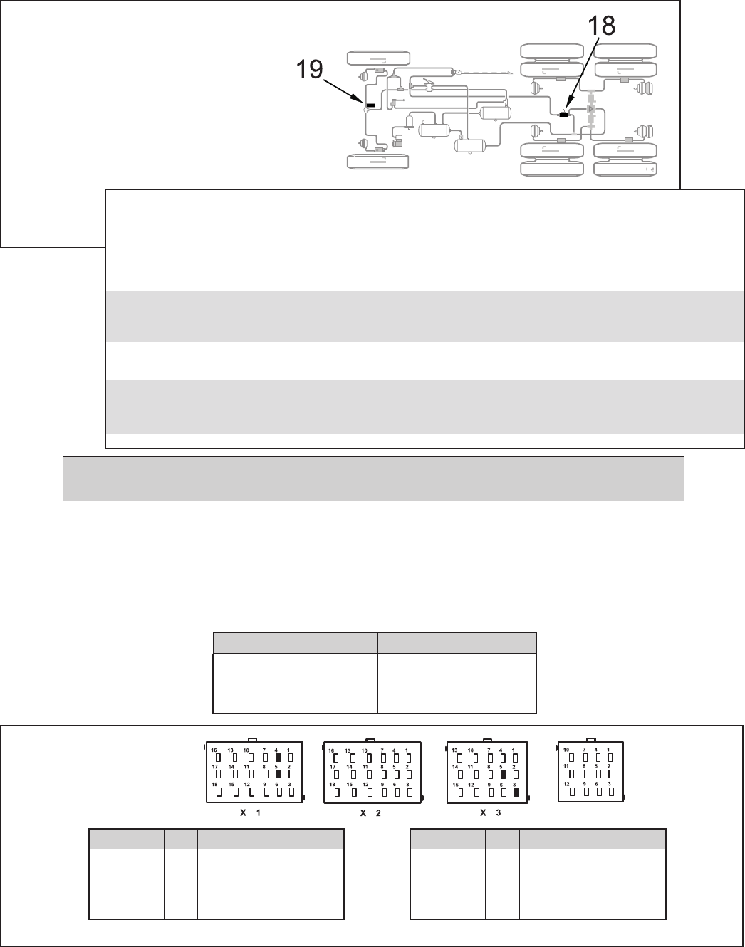
37
Location Measurement
TCV to TCV Common 7 to 19 Ohms
Release, Hold, Common
to Voltage or Ground Open Circuit (no continuity)
Troubleshooting Diagnostic Trouble Codes (DTCs):
Traction Control Valves (TCV)
18 Drive Axle Traction Control Valve
19 Steer Axle Traction Control Valve
1st. Blink
Code Location
Cab-mount ECU:
Looking into wire
harness connector
Traction Control Valve (TCV) Repair Tests:
1. Take all measurements at ECU harness connector pins in order to check wire harness
and traction control valve. Probe the connector carefully so that the terminals are not
damaged.
2. Tractor Control Valve resistance measurements should read:
Connector Pin Traction Control Test
X1
18 Way
4Drive Axle Traction
Control Valve Common
5Drive Axle Traction
Control Valve
Connector Pin Traction Control Test
X3
15 Way
3Steer Axle Traction
Control Valve Common
5Steer Axle Traction
Control Valve
X4
2nd.
Blink
Code
Diagnostic Trouble
Code Description Repair Information
1TCV Solenoid Shorted
to Ground
Verify 7 to 19 ohms between Traction Control Valve (TCV) and TCV
common. Verify no continuity between TCV leads and ground. Check
for corroded/damaged wiring or connectors between the ECU and TCV.
2TCV Solenoid Shorted
to Voltage
Verify 7 to 19 ohms between TCV and TCV common. Verify no continuity
between TCV leads and voltage. Check for corroded/damaged wiring or
connectors between ECU and TCV.
3TCV Solenoid Open
Circuit
Verify 7 to 19 ohms between TCV and TCV common. Check for corroded/
damaged wiring or connectors between ECU and TCV.
4TCV Conguration Error The ECU is not congured for ESP or ATC, but has detected the presence
of a TCV. Verify TCV wiring. Inspect for the presence of a TCV. Verify
the ECU conguration.
NOTE: When troubleshooting Traction
Control Valve DTCs, it may be useful to look
for a potential connection between them and
ECU DTCs (in particular, DTCs 13‑8 and 13‑18
shown on page 36).
ATR valve inspections should include: looking for kinked air hoses; inside the harness socket on the valve for
removed or corroded connector pins; and a test to verify that the ATC valve solenoids are functioning correctly.

38
1st. Blink
Code
21
Location:
Steering Angle Sensor
Troubleshooting Diagnostic Trouble Codes (DTCs):
Steering Angle Sensor (SAS) [Bendix® SAS-60™ Sensor]
2nd.
Blink
Code
Diagnostic Trouble
Code Description Repair Information
1SAS Not Calibrated Steering Angle Sensor (SAS) has not been calibrated.
Perform SAS calibration procedure.
2SAS Calibration
in Progress
SAS calibration procedure is underway.
3SAS Static Signal SAS signal incorrect. Verify the proper installation of the SAS. Verify proper wiring
between the Electronic Control Unit (ECU) and the SAS. Check SAS output.
4SAS Signal Out
of Range
SAS signal incorrect. Verify the proper installation of the SAS. Verify proper wiring
between the ECU and the SAS. Check SAS output. Perform SAS calibration
procedure.
5SAS Signal Reversed SAS signal is reversed. Verify the proper installation of the SAS. Verify proper
wiring between the ECU and the SAS. Check SAS output.
6SAS Invalid Signal SAS signal is invalid. Verify the proper installation of the SAS. Verify proper wiring
between the ECU and the SAS. Check SAS output. Verify that correct SAS is
being used.
7SAS Gradient Error SAS signal is invalid. Verify the proper installation of the SAS. Verify proper wiring
between the ECU and the SAS. Check SAS output. Verify that correct SAS is
being used.
8SAS CAN Time‑out Loss of CAN communications between the ECU and the SAS. Verify proper wiring
between the ECU and the SAS. Check SAS output.
9SAS Long Term
Calibration Error
SAS calibration error. Verify the proper installation of the SAS. Verify proper wiring
between the ECU and the SAS. Check SAS output. Verify that correct SAS is being
used. Verify proper ECU programming. Perform SAS calibration procedure.
10 SAS Plausibility Check ECU has detected incorrect SAS signal as compared to the Yaw Rate sensor signal.
Verify the proper installation of the SAS. Verify proper wiring between the ECU and
the SAS. Check SAS output. Verify that correct SAS is being used. Verify proper
ECU programming. Perform SAS calibration procedure.
11 SAS detected but
not congured
Verify the ECU is congured for ESP.
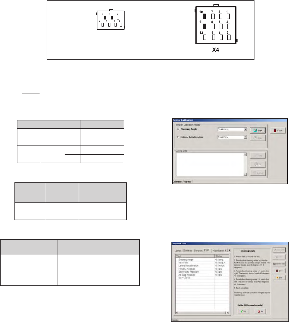
39
Steering Angle Sensor Tests
1. Measure resistance between input voltage and ground
at the sensor wiring harness connector.
Verify continuity between the Electronic Control Unit
(ECU) and SAS‑60 and Yaw Rate Sensor (typically
YAS‑70 or YAS‑60).
Connector Pin Function
SAS 2Voltage Input
1Ground Input
ECU
12 Way X4 11 Power
10 Common
2. Verify wiring between the Steering Angle Sensor and
the ECU.
SAS Wire
Harness
Terminal
ECU Wire
Harness
Terminal Measurement
4 7 Verify Continuity
3 8 Verify Continuity
3. Verify wiring between the Steering Angle Sensor and
power/ground.
SAS Wire Harness
Terminal Measurement
4 to Voltage &
Ground Verify open circuit (no
continuity)
3 to Voltage &
Ground Verify open circuit (no
continuity)
Troubleshooting Diagnostic Trouble Codes (DTCs):
Steering Angle Sensor (SAS) [Bendix® SAS-60™ Sensor]
(continued)
Looking into wire harness connector
Steering Angle Sensor (SAS) Connector
(Note: When checking for voltage at YAW/LAS & SAS, the voltage will only be present momentarily at key ON).
4. To perform a calibration procedure of the Steering Angle
Sensor, Bendix® ACom® Diagnostic Software V6.7.2.5
or higher is required. Using the program, select the
“Configuration” option, followed by the “Calibrate”
option. The following screen should be displayed.
5. Follow the prompts to perform a calibration of the
Steering Angle Sensor.
6. To test the Steering Angle Sensor, ACom V6.7.2.5, or
higher, is required. Using Bendix ACom V6.7.2.5 or
higher, select the “Component Test” option, followed
by the “ESP Test” option. The following screen should
be displayed.
7. Follow the prompts to perform a test of the Steering
Angle Sensor.

40
Troubleshooting Diagnostic Trouble Codes (DTCs):
Yaw Rate Sensor (YRS)
1st. Blink
Code
22
Location:
Yaw Rate Sensor
2nd.
Blink
Code
Diagnostic Trouble
Code Description Repair Information
1YRS Signal Out of
Range The YRS signal is incorrect. Verify the proper installation of the YRS. Verify proper
wiring between the Electronic Control Unit (ECU) and the YRS. Check the YRS output.
Perform the YRS calibration procedure.
2YRS Sensor
Reversed Signal The YRS signal is reversed. Verify the proper installation of the YRS. Verify the wiring
between the ECU and the YRS. Check the YRS output.
3YRS Invalid Signal The YRS signal is invalid. Verify the proper installation of the YRS. Verify proper
wiring between the ECU and the YRS. Check the YRS output. Verify that correct
YRS is being used.
4YRS Gradient Error
5YRS CAN Time‑out Loss of CAN communications between the ECU and the YRS. Verify proper wiring
between the ECU and the YRS. Check the YRS output.
6YRS Static BITE
Error The YRS signal fails static self‑test. Verify the proper installation of the YRS. Verify
proper wiring between the ECU and the YRS. Check the YRS output. Verify that
correct YRS is being used. Verify proper ECU programming. Perform the YRS
calibration procedure.
7YRS Dynamic BITE
Error The YRS signal fails self‑test conducted while vehicle is in motion. Verify the proper
installation of the YRS. Verify proper wiring between the ECU and the YRS. Check the
YRS output. Verify that correct YRS is being used. Verify proper ECU programming.
Perform the YRS calibration procedure.
8YRS Fast Calibration
Error There is a YRS calibration error. Verify the proper installation of the YRS. Verify proper
wiring between the ECU and the YRS. Check the YRS output. Verify that correct YRS is
being used. Verify proper ECU programming. Perform the YRS calibration procedure..
9YRS Static
Calibration Error
10 YRS Normal
Calibration Error There is a YRS calibration error. Verify the proper installation of the YRS. Verify proper
wiring between the ECU and the YRS. Check the YRS output. Verify that correct YRS
is being used. Verify proper ECU programming. Perform the YRS calibration procedure.
12 YRS Plausibility
Check (Ref Yaw
Rate)
The ECU has detected an incorrect YRS signal. Verify the proper installation of the
YRS. Verify proper wiring between the ECU and the YRS. Check the YRS output.
Verify that correct YRS is being used. Verify proper ECU programming. Perform the
YRS calibration procedure.
13 YRS Plausibility Error
(Inside Model Based
Limits)
14 YRS Plausibility
Error (Outside Model
Based Limits)
15 YRS ‑ SAS Signal
Cross‑check
Incomplete
The ECU (if congured) must conrm that YRS and SAS signals match. The vehicle
must be exposed to an S‑shaped driving maneuver for this DTC to automatically clear.
If the DTC does not clear even after the S‑shaped driving maneuver, check and correct
the orientation of the YRS and then repeat the maneuver.
16 YRS ‑ Vibration
Detected Inspect the YRS mounting and verify it is securely mounted. Note that the YRS may
not be relocated from the OEM‑installed position on vehicle without written Bendix
Engineering approval.
17 YRS Detected But
Not Congured
Verify that the ECU is congured for ESP.
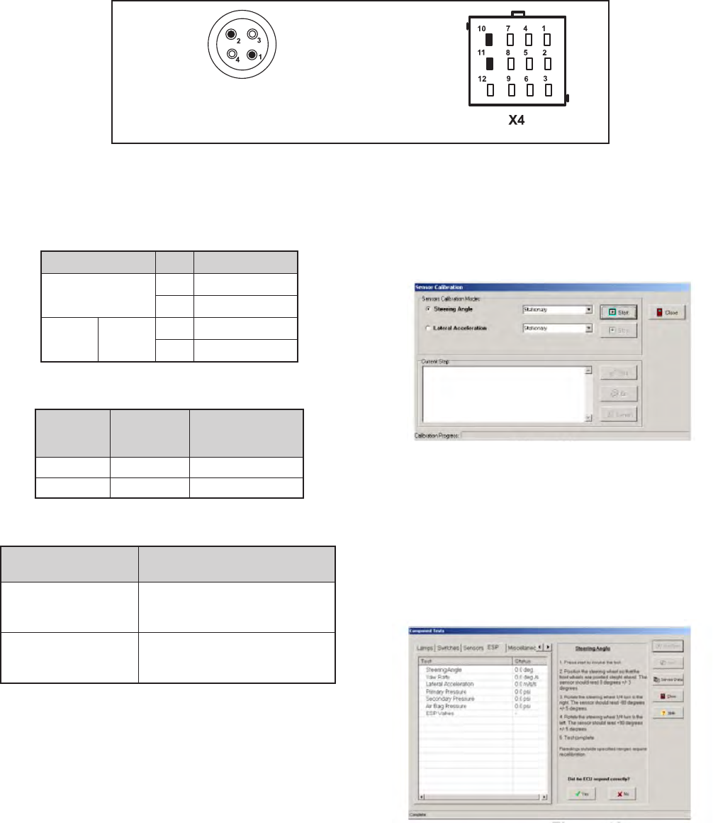
41
Troubleshooting Diagnostic Trouble Codes (DTCs):
Yaw Rate Sensor (YRS) (continued)
Yaw Rate Sensor Tests
1. Verify continuity between the Electronic Control Unit
(ECU) and the Yaw Rate Sensor (typically YAS‑70 or
YAS‑60).
Connector Pin Function
YRS 2Voltage Input
1Ground Input
ECU
12 Way X4 11 Power
10 Common
2. Verify wiring between the Yaw Rate Sensor and the
ECU.
YRS Wire
Harness
Terminal
ECU Wire
Harness
Terminal Measurement
4 7 Verify Continuity
3 8 Verify Continuity
3. Verify wiring between the Yaw Rate Sensor and power/
ground.
YRS Wire Harness
Terminal Measurement
4 to Voltage &
Ground Verify open circuit (no
continuity)
3 to Voltage &
Ground Verify open circuit (no
continuity)
Looking into wire harness connector
Yaw Connector
(Note: When checking for voltage at YAW/LAS & SAS, the voltage will only be present momentarily at key ON.).
4. To perform a calibration procedure of the Yaw Rate
Sensor, ACom® Diagnostic Software V6.7.2.5 (or
higher) is required. Using the program, select the
“Configuration” option, followed by the “Calibrate”
option. The following screen should be displayed.
5. Follow the prompts to perform a calibration of the Yaw
Rate Sensor.
6. To test the Yaw Rate Sensor, ACom V6.7.2.5, or higher,
is required. Using Bendix ACom V6.7.2.5 or higher,
select the “Component Test” option, followed by the
“ESP Test” option. The following screen should be
displayed.
7. Follow the prompts to perform a test of the Yaw Rate
Sensor.

42
Troubleshooting Diagnostic Trouble Codes (DTCs):
Lateral Acceleration Sensor (LAS)
1. Follow the steps shown in the Yaw Rate Sensor
troubleshooting section for calibration and
troubleshooting of the Lateral Acceleration Sensors
(previous page).
1st. Blink
Code
23
Location:
Lateral Acceleration
Sensor
2nd.
Blink
Code
Diagnostic Trouble
Code Description Repair Information
1LAS Signal Out of
Range LAS signal incorrect. Verify the proper installation of the YRS/LAS. Verify
proper wiring between the Electronic Control Unit (ECU) and the YRS/LAS.
Check YRS/LAS output. Perform LAS calibration procedure.
2LAS Calibration in
Progress
LAS calibration procedure is underway.
3 LAS Static
Calibration Error
LAS calibration error. Verify the proper installation of the YRS/LAS. Verify
proper wiring between the ECU and the YRS/LAS. Check YRS/LAS output.
Verify that correct YRS/LAS is being used. Verify proper ECU programming.
Perform LAS calibration procedure.
4 LAS Long Term
Calibration Error
LAS calibration error. Verify the proper installation of the YRS/LAS. Verify
proper wiring between the ECU and the YRS/LAS. Check YRS/LAS output.
Verify that correct YRS/LAS is being used. Verify proper ECU programming.
Perform LAS calibration procedure.
5LAS Plausibility
Error (Inside ECU‑
specic Limits)
ECU has detected an incorrect LAS signal. Verify the proper installation of the
YRS/LAS. Verify proper wiring between the ECU and the YRS/LAS. Check
YRS/LAS output. Verify that correct YRS/LAS is being used. Verify proper
ECU programming. Perform LAS calibration procedure.
6LAS Plausibility
Error (Outside ECU
–specic Limits)
ECU has detected an incorrect LAS signal. Verify the proper installation of the
YRS/LAS. Verify proper wiring between the ECU and the YRS/LAS. Check
YRS/LAS output. Verify that correct YRS/LAS is being used. Verify proper
ECU programming. Perform LAS calibration procedure.
7 Erratic ESP Sensor
Signal
ECU has detected an erratic signal. Verify the proper installation of the YRS/
LAS. Verify proper wiring between the ECU and the YRS/LAS. Check YRS/
LAS output. Verify that correct YRS/LAS is being used. Verify proper ECU
programming. Perform LAS calibration procedure.
(Note: When checking for voltage at YRS/LAS & SAS, the voltage will only be present momentarily at key ON.).
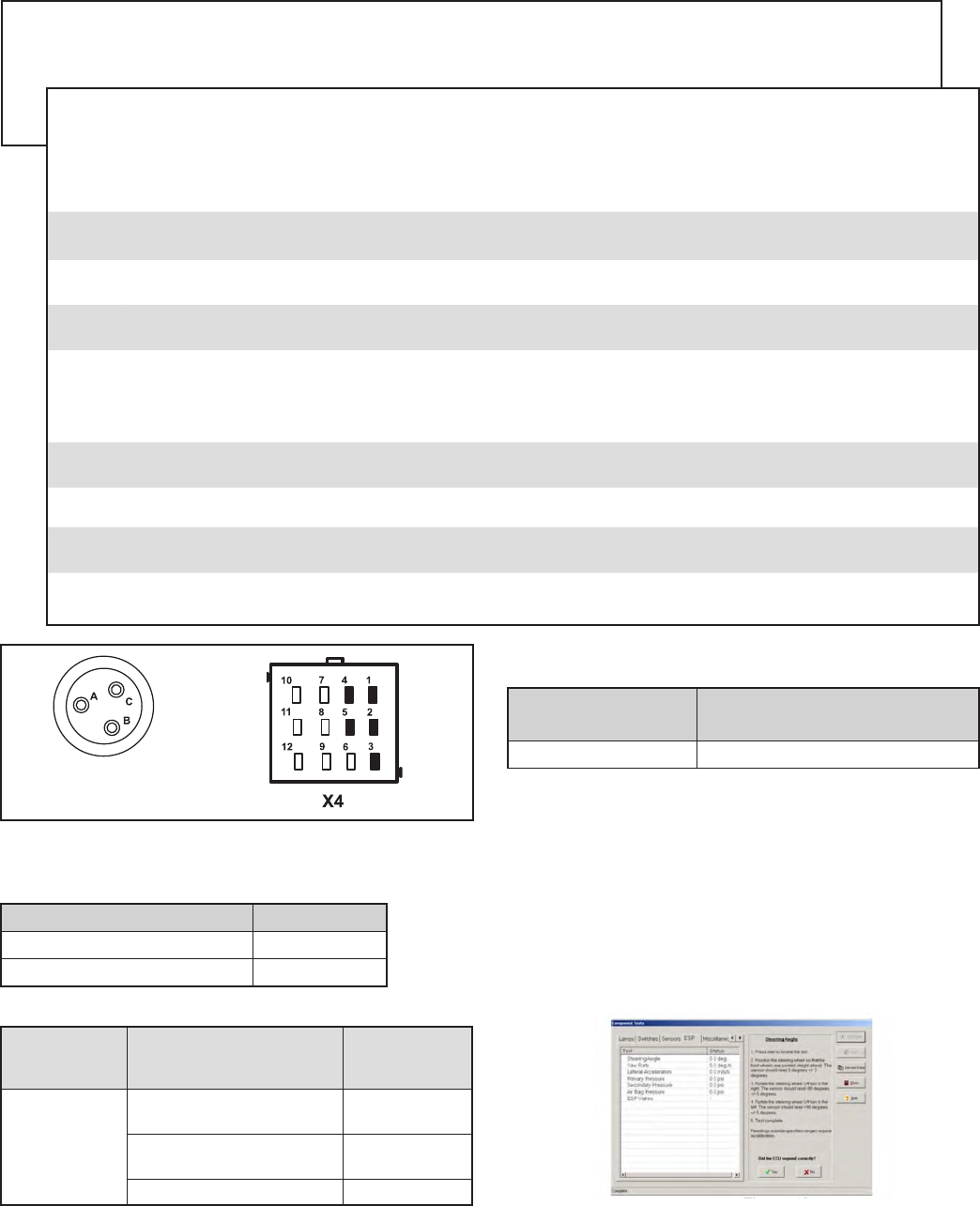
43
Troubleshooting Diagnostic Trouble Codes (DTCs):
Brake Demand/Load Sensors
Brake Demand/Load Sensor Tests
1. Verify continuity between the ECU and the pressure
sensor power and ground.
Power and Ground Input Test Measurement
B = Power Input X4 ‑ 4 Power
A = Ground Input X4 ‑ 1 Common
2. Verify wiring between the Load Sensor and the ECU.
Load Sensor
Wire Harness
Terminal
ECU Wire Harness
Terminal Measurement
C
X4 ‑ 2 Brake Demand
Sensor (primary brake circuit) Verify Continuity
X4 ‑ 5 Brake Demand Sensor
(secondary brake circuit) Verify Continuity
X4 ‑ 3 Load Sensor Verify Continuity
Looking into wire
harness connector
3. Verify wiring between the Load Sensor and power/
ground.
Load Sensor
Harness Terminal Measurement
C to Voltage & Ground Verify open circuit (no continuity)
4. To perform a calibration procedure of the Brake Demand
Sensor(s), ensure that the air system is fully charged.
Apply ignition power, and wait 30 seconds. Perform
a full application of the service brake and hold for 5
seconds. Release the service brake.
5. To test the Brake Demand Sensor and/or the Load
Sensor, Bendix® ACom® Diagnostic Software V6.7.2.5
or higher is required. Using the program, select the
“Component Test” option, followed by the “ESP Test”
option. The following screen should be displayed.
6. Follow the prompts to test the Brake Demand Sensor(s)
and/or the Load Sensor.
1st. Blink
Code
24
Location:
Brake Demand/
Load Sensor
2nd.
Blink
Code
Diagnostic Trouble
Code Description Repair Information
1 PS1 Open or
Shorted
Check wiring between Brake Demand Sensor (primary brake circuit) and
Electronic Control Unit (ECU). Verify operation of pressure sensor.
2 PS2 Open or
Shorted
Check wiring between Brake Demand Sensor (secondary brake circuit) and ECU.
Verify operation of pressure sensor.
3 PS3 Open or
Shorted
Check wiring between Load Sensor and ECU. Verify operation of pressure sensor.
4PS1/2
Plausibility Error
ECU has detected an invalid pressure sensor signal from one of the Brake
Demand Sensors.
5 PS Supply
Voltage Error
Incorrect supply voltage to the sensors. Verify the proper voltage at sensor
connectors. Verify wiring between the ECU and the sensors. Verify the proper
output voltage from the ECU (Specically, ensure that X4‑4 PS_SPL is not
shorted to ground).
6 PS Not
Calibrated
Perform static sensor calibration procedure. (NOTE: When replacing an ECU,
this DTC may occur.)
7PS Error Verify operation of pressure sensor.
8 PS Supply
Voltage Error
Incorrect supply voltage to sensors. Verify the proper voltage at sensor connectors.
Verify wiring between ECU and the sensors. Verify the proper output voltage from ECU.
9 PS Not
Congured
Check for presence of pressure sensors. Make sure ESP is enabled.

44
Troubleshooting Diagnostic Trouble Codes (DTCs):
Valves Miscellaneous
1st. Blink
Code
25
Location:
Valves
2nd.
Blink
Code
Diagnostic Trouble
Code Description Repair Information
1Differential Lock
Solenoid Open Verify resistance between Diff solenoid and Diff common. Check for corroded
/damaged wriing or connectors between the Electronic Control Unit (ECU)
and the Diff solenoid.
2 Differential Lock
Solenoid Shorted to
Ground
Verify no continuity between the Diff Lock Solenoid and ground. Check for
corroded/damaged wiring or connectors between the ECU and Diff Lock
Solenoid.
3 Differential Lock
Solenoid Shorted to
Voltage
Verify no continuity between the Diff Lock Solenoid and voltage. Check for
corroded/damaged wiring or connectors between the ECU and Diff Lock
Solenoid.
4 I/O 3 Open Circuit Verify resistance for I/O3 circuit. Check for corroded / damaged wiring or
connector between ECU and I/O.
5 I/O 3 shorted to
Ground
Check for a short circuit condition between ground and the I/O 3 circuit
Verify resistance between Input /Output and ground is open
6 I/O 3 Shorted to
Battery
Check for a short circuit condition between voltage and the I/O 3 circuit
Verify resistance between Input /Output and voltage is open
7Output Conguration
Error ‑ Diff
Mismatch between ECU conguration and Diff valve
8Output Conguration
Error ‑ I/O 3
Mismatch between ECU conguration and I/O3

45
Troubleshooting Diagnostic Trouble Codes (DTCs):
Bendix® ESP® system-related
1st. Blink
Code
26
Location:
J1939 Bendix® ESP®
system-related
2nd.
Blink
Code
Diagnostic Trouble Code
Description Repair Information
1 J1939 CAN Time‑out of ESP
Message
Check for damaged or reversed J1939 wiring. Check for damaged or
corroded connectors. Verify message is being transmitted on J1939 link.
Verify the Electronic Control Unit (ECU) conguration
2 Time‑out or Invalid CAN data
–CCVS 2 ESP Message
Check for damaged or reversed J1939 wiring. Check for damaged or
corroded connectors. Verify message is being transmitted on J1939 link.
Verify the ECU conguration
3 Time‑out or Invalid CAN data
–Electronic Engine Controller 1
ESP Message
Check for damaged or reversed J1939 wiring. Check for damaged or
corroded connectors. Verify the presence of engine ECU on J1939 link.
Verify message is being transmitted on J1939 link. Verify data for driver's
demand torque, actual engine torque, engine speed is correct. Verify the
ECU conguration
4 Time‑out or Invalid CAN data
–EEC2 ESP Message
Check for damaged or reversed J1939 wiring. Check for damaged or
corroded connectors. Verify the presence of engine ECU on J1939 link.
Verify message is being transmitted on J1939 link. Verify acceleration
pedal position and acceleration pedal status is correct. Verify the ECU
conguration
5 Time‑out or Invalid CAN data
– Driveline Line Retarder ESP
Message
Check for damaged or reversed J1939 wiring. Check for damaged or
corroded connectors. Verify the presence of a retarder on J1939 Link.
Verify that the message is being transmitted. Verify that the data is correct
for torque / speed control. Verify the ECU conguration
6 Time‑out or Invalid CAN data –
Engine Retarder ESP Message
Check for damaged or reversed J1939 wiring. Check for damaged or
corroded connectors. Verify the presence of a retarder on J1939 Link.
Verify that the message is being transmitted. Verify that the data is correct
for torque / speed control. Verify the ECU conguration
7 Time‑out or Invalid CAN
data – Exhaust Retarder ESP
Message
Check for damaged or reversed J1939 wiring. Check for damaged or
corroded connectors. Verify the presence of a retarder on J1939 Link.
Verify that the message is being transmitted. Verify that the data is correct
for torque / speed control. Verify the ECU conguration
8 Time‑out or Invalid CAN data –
PROP XBR ESP Message
Check for damaged or reversed J1939 wiring. Check for damaged or
corroded connectors. Verify the presence of Radar on J1939 link. Verify
message is being transmitted. Verify the ECU conguration
9 Time‑out or Invalid CAN data
– Transmission Retarder ESP
Message
Check for damaged or reversed J1939 wiring. Check for damaged or
corroded connectors. Verify the presence of a retarder on J1939 Link. Verify
that the message is being transmitted. Verify that the data in torque/speed
control. Verify the ECU conguration
10 Time‑out or Invalid CAN data
–Electronic Transmission
Controller 1 ESP Message
Check for damaged or reversed J1939 wiring. Check for damaged or
corroded connectors. Verify the presence of transmission ECU on J1939
link. Verify that the message is being transmitted. Verify that the data for
shift in process, torque conguration lock , driveline engaged is correct.
Verify the ECU conguration
11 Time‑out or Invalid AUXI/O –
ESP Message
Check for damaged or reversed J1939 wiring. Check for damaged or
corroded connectors. Verify that the message is being transmitted. Verify
that the data for reference torque is correct. Verify the ECU conguration

46
Troubleshooting Diagnostic Trouble Codes (DTCs):
J1939 Bendix® ESP® system-related (continued)
1st. Blink
Code
26
Location:
J1939 Bendix® ESP®
system-related
2nd.
Blink
Code
Diagnostic Trouble Code
Description Repair Information
12 Time‑out or invalid data for
Conguration of Electronic
Engine Controller 1 ESP
Message
Check for damaged or reversed J1939 wiring. Check for damaged or
corroded connectors. Verify the presence of engine on J1939 link. Verify
that the message is being transmitted. Verify that the data for reference
torque is correct. Verify the Electronic Control Unit (ECU) conguration
13 Invalid Data Transfer Time‑out
of EC1 ESP Message
Check for damaged or reversed J1939 wiring. Check for damaged or
corroded connectors. Verify the presence of engine on J1939 link. Verify
that the message is being transmitted. Verify that the data for reference
torque is correct. Verify the ECU conguration
14 Time‑out or invalid data for
Conguration of Driveline Line
Retarder ESP Message
Check for damaged or reversed J1939 wiring. Check for damaged or
corroded connectors. Verify the presence of a retarder on J1939 link. Verify
that the message is being transmitted. Verify that the data for reference
torque is correct. Verify the ECU conguration
15 Time‑out or invalid CAN data
–Electronic Engine Controller
ESP Message
Check for damaged or reversed J1939 wiring. Check for damaged or corroded
connectors. Verify the presence of engine ECU on J1939 link. Verify the
presence of engine ECU on J1939 link. Verify the ECU conguration
16 Time‑out or invalid CAN data
–Electrionic Transmission
Controller 2‑ message required
for ESP
Check for damaged or reversed J1939 wiring. Check for damaged or
corroded connectors. Verify the presence of transmission ECU on J1939
link. Verify that the message is being transmitted. Verify that the data for
current gear is correct. Verify the ECU conguration
17 Time‑out or invalid data
for Conguration of Engine
Retarder ESP Message
Check for damaged or reversed J1939 wiring. Check for damaged or
corroded connectors. Verify the presence of a retarder on J1939 link. Verify
message is being transmitted. Verify the ECU conguration
18 Time‑out or invalid data for
Conguration of Exhaust
Retarder ESP Message
Check for damaged or reversed J1939 wiring. Check for damaged or
corroded connectors. Verify the presence of a retarder on J1939 link. Verify
message is being transmitted. Verify the ECU conguration
19 Time‑out or invalid data for
Conguration of Transmission
Retarder ESP Message
Check for damaged or reversed J1939 wiring. Check for damaged or
corroded connectors. Verify the presence of Radar on J1939 link. Verify
the ECU conguration
20 Invalid Data Transfer Time‑out
of Driveline Line Retarder ESP
Message
Check for damaged or reversed J1939 wiring. Check for damaged or
corroded connectors. Verify the presence of a retarder on J1939 link. Verify
message is being transmitted. Verify the ECU conguration
21 Invalid Data Transfer Time‑out
of Engine Retarder ESP
Message
Check for damaged or reversed J1939 wiring. Check for damaged or
corroded connectors. Verify the presence of a retarder on J1939 link. Verify
message is being transmitted. Verify the ECU conguration
22 Invalid Data Transfer Time‑out
of Exhaust Retarder ESP
Message
Check for damaged or reversed J1939 wiring. Check for damaged or
corroded connectors. Verify the presence of a retarder on J1939 link. Verify
the presence of a retarder on J1939 link. Verify message is being transmitted.
Verify the ECU conguration

47
Troubleshooting Diagnostic Trouble Codes (DTCs):
J1939 Bendix® ESP® system-related (continued)
1st. Blink
Code
26
Location:
J1939 ESP-related
2nd.
Blink
Code
Diagnostic Trouble Code
Description Repair Information
23 Time‑out or invalid CAN data –
CCVS ESP Message
Check for damaged or reversed J1939 wiring. Check for damaged or
corroded connectors. Verify message is being transmitted on J1939 link.
Verify data for park brake, brake lamp switch, clutch and tachograph. Verify
the Electronic Control Unit (ECU) conguration
24 Time‑out or invalid CAN data –
TCO ESP Message
Check for damaged or reversed J1939 wiring. Check for damaged or
corroded connectors. Verify message is being transmitted. Verify the ECU
conguration
25 Invalid Data Transfer Time‑out
of Driveline Line Retarder
ESP Message
Check for damaged or reversed J1939 wiring. Check for damaged or
corroded connectors. Verify the presence of a retarder on J1939 link. Verify
message is being transmitted. Verify the ECU conguration
26 ESP‑related CM3 Time‑out
at J1939
Check for damaged or reversed J1939 wiring. Check for damaged or
corroded connectors. Verify message is being transmitted. Verify the ECU
conguration
27 Time‑out of message or invalid
data received from transmission
transfer information on J1939 ‑
message required for ESP
Check for damaged or reversed J1939 wiring. Check for damaged or
corroded connectors. Verify message is being transmitted. Verify the ECU
conguration
28 Time‑out or invalid CAN data –
Electronic Axle Controller 1ESP
Message
Check for damaged or reversed J1939 wiring. Check for damaged or
corroded connectors. Verify message is being transmitted. Verify the ECU
conguration
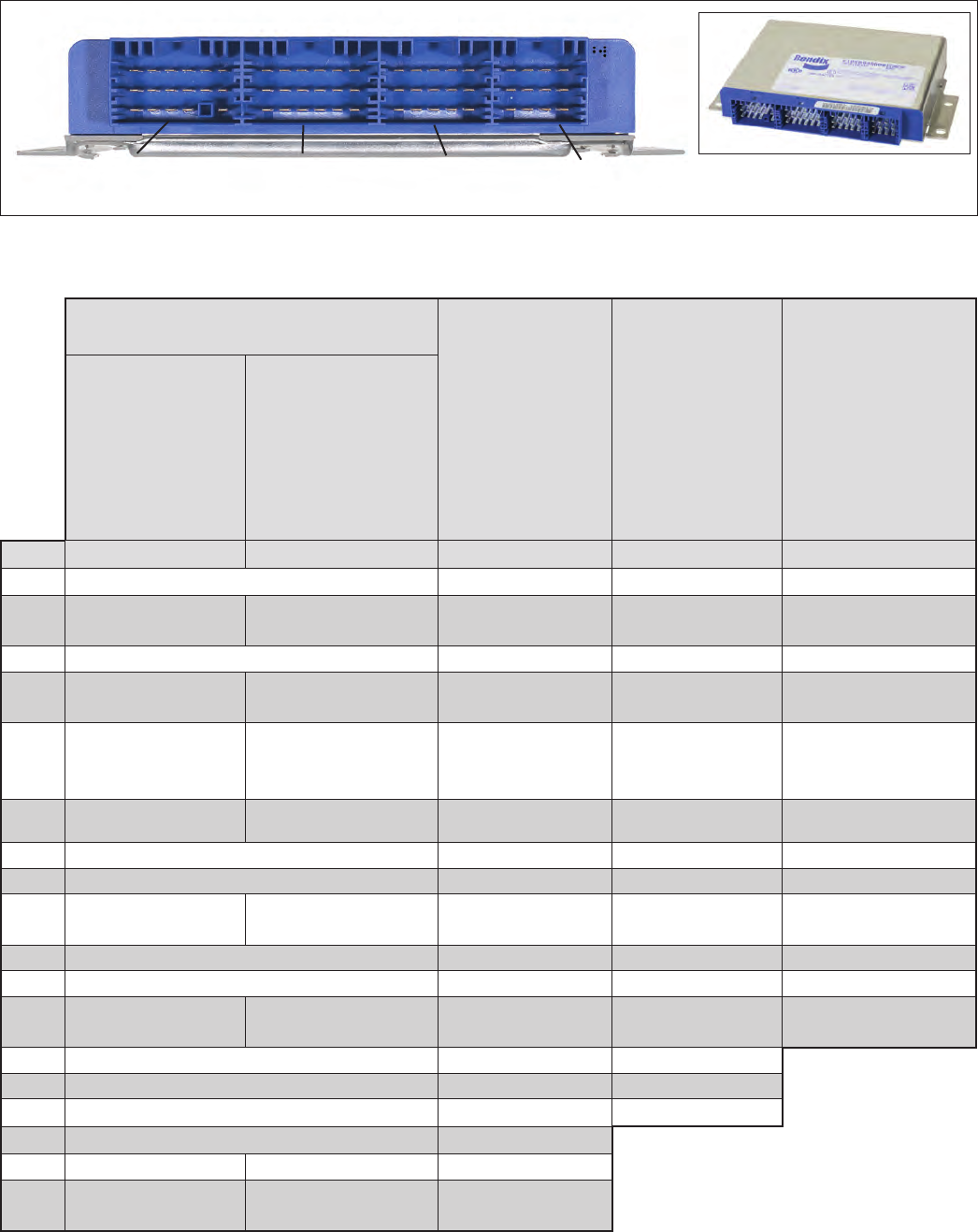
48
Controllers utilize four (4) AMP connectors for wire harness connections.
Bendix ESP EC-80 Controller
Bendix® ESP® EC-80™ Controller Wire Harness Connector Part Numbers and Pin Assignments:
X1
CONNECTOR
X2
CONNECTOR
X3
CONNECTOR
X4
CONNECTOR
Troubleshooting: Connectors
X1 Connector Pin Assignments
Vary by Part Number:
X2 Connector
Pin
Assignments
X3 Connector
Pin
Assignments
X4 Connector Pin
Assignments
K098920R000
K098921R000
K103428R000
K103429R000
K105094R000
K105095R000
K105096R000
K105097R000
K105303R000
Pin Designation Designation Designation Designation Designation
1Ground PMV SA Left HLD ABS ORS Pressure Sensor CMN
2 Trailer ABS Indicator HSA Disable Switch PMV SA Left REL Diff. Lock Solenoid*Brake Demand Primary
Circuit Signal
3Ignition PMV SA Left CMN TCV CMN (SA) Load Sensor Signal
4 TCV CMN (DA) TCV (DA) PMV SA Right HLD PMV AA Left HLD Pressure Sensor
Supply
5 TCV (DA) TCV CMN (DA) WSS SA Left (+) TCV (SA)
Brake Demand
Secondary Circuit
Signal
6ATC/ESP Indicator
and ATC ORS TPMS Ground PMV SA Right CMN PMV AA Left CMN PMV Trailer HLD
7J1939 High PMV SA Right REL PMV AA Left REL Sensor CAN Low
8J1939 Low WSS SA Left (‑) Stop Lamp Output Sensor CAN High
9 SLS Input TPMS
Communications PMV DA Right CMN PMV AA Right CMN PMV Trailer REL
10 WSS DA Right (+) PMV DA Right HLD PMV AA Right HLD Sensor CAN Common
11 WSS DA Right (‑) WSS SA Right (+) WSS AA Left (+) Sensor CAN Supply
12 ABS Indicator
Ground Reserved PMV DA Left CMN WSS AA Right (+) PMV Trailer CMN
13 J1939 High 2 PMV DA Right REL PMV AA Right REL
14 J1939 Low 2 WSS SA Right (‑) WSS AA Left (‑)
15 ABS Indicator Interlock WSS DA Left (+) WSS AA Right (‑)
16 Battery PMV DA Left HLD
17 Retarder ATC/ESP Indicator PMV DA Left REL
18 ABS Dash Indicator ATC Disable Switch or
Diagnostic Switch WSS DA Left (‑)
*AWD vehicles only (AWD Transfer Case.)
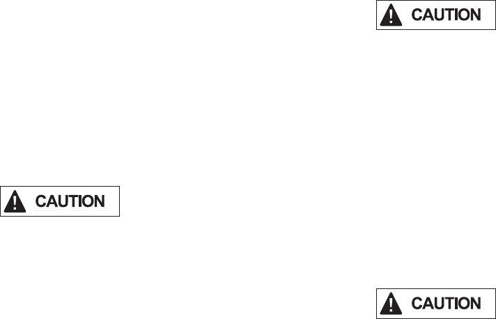
49
ABS/ATC WIRING
Electronic Control Unit (ECU) Wiring Harness
Connectors
The Bendix® ESP® EC‑80™ Controller is designed to
interface with AMP MCP 2.8 connectors as referenced in
Figure 21. Follow all AMP requirements for the repair of
wire harnesses.
All wire harness connectors must be properly seated. The
use of secondary locks is strongly advised.
All unused ECU connectors must be covered and
receive proper environmental protection.
ABS Wiring Requirements
As a matter of good practice and to ensure maximum
system robustness, always use the maximum size wire
supported by the wire harness connectors for battery,
ignition, ground, Pressure Modulator Valve (PMV), Traction
Control Valve (TCV), Interaxle Differential Lock and
indicator lamp circuits.
All sensor and serial communications circuits (J1939) must
use twisted pair wiring (one to two twists per inch). See
the appropriate Society of Automotive Engineers (SAE)
document for additional details.
All wires must be carefully routed to avoid contact
with rotating elements. Wiring must be properly
secured approximately every 6 to 12 inches using UV
stabilized, non-metallic hose clamps or bow-tie cable
ties to prevent pinching, binding or fraying.
It is recommended that wires be routed straight out of a
connector for a minimum of three inches before the wire
is allowed to bend.
Battery and ground wires should be kept to a minimum
length.
If convoluted tubing is used, its I.D. must match the size
of the wire bundle as closely as possible.
Wire harness lengths must be carefully selected for
the vehicle. Excess lengths of wire are not to be
wound to form coils, instead re-route, repair or replace
wire harness to avoid the possibility of electrical
interference and wire damage. Do not attempt to
stretch harnesses that are too short, since mechanical
strain can result in wire breakage.
Bendix® SAS-60™ Sensors and YAS-60™, or
YAS-70X™, Sensor Wiring
If it is necessary to replace the wiring that connects the
Bendix SAS‑60 or the Yaw Rate sensor to the ECU, it
is important to use the same wiring as that used by the
vehicle OEM.
Troubleshooting: Wiring

50
ABS Component Connector Wire Terminal Wire Seal/
Plug Terminal
Lock Terminal Crimp Tool
In‑Cab Controller Harness
17‑Way AMP
MCP 2.8 (X1) 1718091‑1
927768‑9
1 ‑ 2.5 mm2
X1‑12 & 18
968874
2.5 ‑ 4 mm2
968873
1.0 ‑ 2.5 mm2
N/A
967634
539723‑2
In‑Cab Controller Harness
18‑Way AMP
MCP 2.8 (X2) 8‑968974‑1
N/A
In‑Cab Controller Harness
15‑Way AMP
MCP 2.8 (X3) 8‑968973‑1
Controller Harness
12‑Way AMP
MCP 2.8 (X4) 8‑968972‑1
ABS Modulator Harness
AMP Twist‑Lock
(Bayonet) 1‑967325‑2
929975‑1
N/A
539635‑1
ATC Modulator Harness
AMP Twist‑Lock
(Bayonet) 1‑967325‑3
ABS Modulator Harness
3‑pin Packard
Metri‑Pack
280 Series 12040977 12077411 12015323 12034145 12155975
TE® Connectivity / AMP Terminal Removal Tool. Newark® Part
No. 78H0240. Manufacturer Part Number 1‑1579007‑6
Bendix® WS-24™ Wheel Speed Sensor Connectors
Packard® GT
150 series Packard
Metripack 150.2
series
Deutsch®
DTM06 series Packard
Metripack 280
series (female)
Packard
Metripack 280
series (male)
Deutsch DT04
series Standard round
two pin
Yaw Rate Sensor Wire Harness Connectors (4 contact):
Straight Connector: Schlemmer® 9800 351 (shown)
AMP® Connector 2‑967325‑1
ITT® Cannon® Connector 121583‑001
90 degree Connector: Schlemmer 9800 331
Yaw Rate Sensor Wire Harness
Contact Pin Terminals:
Schlemmer 7814 125
AMP 0‑962981‑1
ITT Cannon 031‑8717‑120
Bendix® SAS-60™ Sensor Connectors:
Robert Bosch® 1 928 404 025,
Robert Bosch 1 928 498 001
One Meter Adapter to Connector:
Bendix 5015242 (shown)
Packard 12092162, pins 12064971
Brake Demand Sensor/Load Sensor
Wire Harness Connectors:
Metri‑Pack® (Packard) 1206 5287
Contact Pins:
Packard 1210 3881
FIGURE 21 - BENDIX ESP® EC‑80™ CONTROLLER COMPONENT CONNECTORS
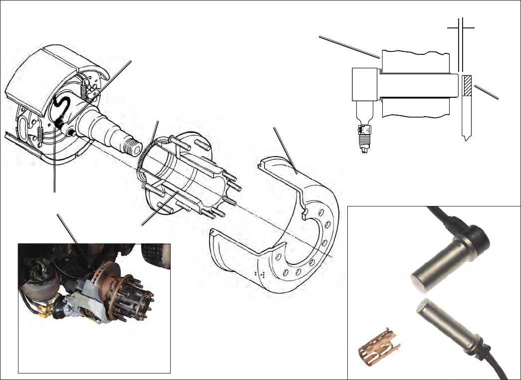
51
Wheel Speed Sensor Wiring
Route sensor wiring coming out of the wheel ends away
from moving brake components. Sensor wiring needs to
be secured to the axle to prevent excess cable length and
wiring damage. It is required that cable ties be installed
to the sensor wire within 3 inches (76.2 mm) of the sensor
head to provide strain relief.
Following the axle, the sensor wires must be attached
along the length of the service brake hoses using cable ties
with ultraviolet protection and secured every 6 to 8 inches
(152 to 203 mm). Sufcient – but not excessive – cable
length must be provided to permit full suspension travel and
steering axle movement. Install wires so that they cannot
touch rotating elements such as wheels, brake discs or
drive shafts. Radiation protection may be necessary in
the area of brake discs.
FIGURE 22 - BENDIX® WS‑24™ WHEEL SPEED SENSOR INSTALLATION (S‑CAM AND AIR DISC BRAKE)
Speed Sensor
Mounting Block
100 Tooth (typical)
Speed Sensor
Exciter Ring
WS-24™ Speed
Sensor
Hub Assembly
WS-24™ Speed
Sensor
100 Tooth
Exciter
Ring
Mounting
Block
Max. Gap
(Sensor to Exciter)
.015 Inches
Brake Drum
Bendix does not recommend using standard tie‑wraps to
secure wiring harnesses directly to rubber air lines. This
may cause premature wiring failure from the pressure
exerted on the wiring when air pressure is applied through
the air line. Non‑metallic hose clamps or bow‑tie tie‑wraps
are preferred.
The use of grommets or other suitable protection is
required whenever the cable must pass through metallic
frame members.
All sensor wiring must utilize twisted pair wire, with
approximately one to two twists per inch.
It is recommended that wires be routed straight out of a
connector for a minimum of three inches before the wire
is allowed to bend.
90° Speed
Sensors
Straight Speed
Sensors
Sensor
Clamping
Sleeve
Troubleshooting: Wiring (Continued)
Air Disc Brake
Note: Ensure that the sensor wiring is
routed to avoid chang from moving
parts (including rotors and steering
components.)
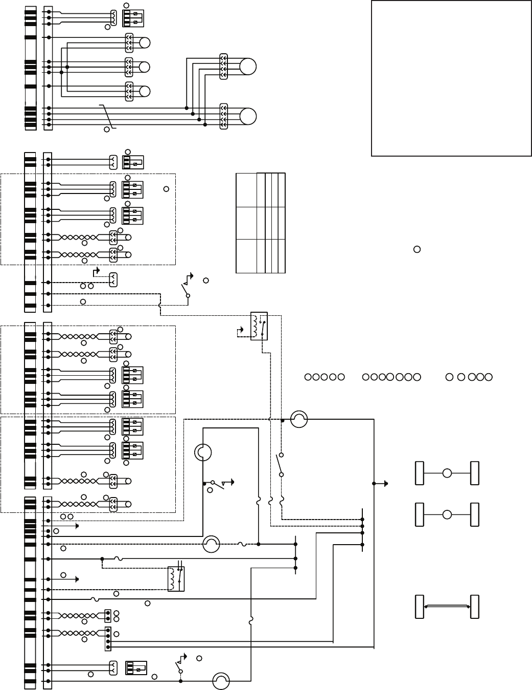
52
FIGURE 23 - STANDARD WIRING SCHEMATIC FOR ECUs LISTED ABOVE
Troubleshooting: Wiring Schematic A
11
2
9
11
19 CAN SENSOR WIRING - 18 AWG (FOUR CONDUCTOR TWISTED WIRE REQUIRED).
1. RETARDER CONTROL VIA RELAY OR SAE J1939.
2 DIAGNOSTICS PER SAE J1587 OR J1939.
3 DIAGNOSTIC BLINK CODE SWITCH (MOMENTARY SWITCH).
4 ATC ENGINE CONTROL PER SAE J1939.
5A
5A
5 PRESSURE MODULATOR VALVE (PMV): BENDIX M-32, M-32QR, M-40X
7 WHEEL SPEED SENSOR (WSS): BENDIX WS-24
9 TRACTION CONTROL VALV E (TCV).
10 SERIAL COMMUNICATIONS - 18 AW G (TWISTED PA IR REQUIRED).
NOTES
AA
8
19
J1587 B
J1587 A
J1939_LO
J1939_HI
BATTERY
RETARDER
GROUND
ADDITIONAL AXLE 21
11
16. THIS SYSTEM WIRING CONNECTION SCHEMATIC IS FOR AN EC-80 ECU DESIGNED AS A SERVICE REPLACEMENT FOR EC-60 ADVANCED.
17 POLE
18 POLE
15 POLE
WSS
DRIVE
AXLE
RIGHT
WSS
DRIVE
AXLE
LEFT
WSS
STEER
AXLE
RIGHT
IGNITION
TRAILER ABS IND.
ABS IND.
SLS INPUT
WSS_DR+
WSS_DR-
WSS_DL+
WSS_DL-
13 14 7816 17 13218 910 11 15 18
30A
WSS
STEER
AXLE
LEFT
DIFF
LOCK
SOL
PMV_DR_HLD
PMV_DR_REL
PMV_DR_CMN
PMV_DL_HLD
PMV_DL_REL
PMV_DL_CMN
PMV_SR_HLD
PMV_SR_REL
PMV_SR_CMN
PMV_SL_HLD
PMV_SL_REL
PMV_SL_CMN
9
TRACTION
CONTROL
VALV E
ABS ORS
WSS_SR+
WSS_SR-
WSS_SL+
WSS_SL-
10 13
916 17
12 47612
31
11 14 58
WSS_AR+
WSS_AR-
WSS_AL+
WSS_AL-
5A
DIFF
PMV_AR_HLD
PMV_AR_REL
PMV_AR_CMN
ST
OP LAMP OUTPUT
TCV_SA_CMN
TCV_SA
12 15 11 14
23
5
810 13
9
WSS
ADD
AXLE
RIGHT
WSS
ADD
AXLE
LEFT
6
17 WHEN X1 IS DISCONNECTED FROM ECU, THE INTERLOCK SHORTS THE INDICATOR CIRCUIT TO GROUND, ILLUMINATING THE
ABS INDICATOR.
STOP LAMP
TRAILER ABS
DASH INDICATOR
6 PMV CONNECTOR TWIST-LOCK PACKARD
COMMON (CMN) PIN 2 PIN B
HOLD (HLD) PIN 3 PIN C
RELEASE (REL) PIN 1 PIN A
8 WSS WIRING - 18 AWG (TWISTED PAIR REQUIRED).
5A
18
20
20 MOMENTARY SWITCH.
18 STOP LAMP SWITCH INPUT REQUIRED FOR ATC AND ALL-WHEEL DRIVE VEHICLES.
MAY BE PROVIDED VIA HARDWARE INPUT OR J1939 COMMUNICAT ION.
20
21 ADDITIONAL AXLE WSS AND PMV INSTALLED PER EC-80 CONFIGURATION (6S/4M, 6S/6M).
ESP/ATC
DASH
INDICATOR
ABS DASH
INDICATOR
12
STOP LAMP
RELAY
18
6 6 6
5 5 5
7 7
77
7
15
IND. INTERLOCK
7
4
5A
11
X2
X2
5A
(OPTIONAL)
RETARDER RELAY
X3
X3
8
1010 88 8 8
X1
X1
11 DOTTED LINES: SPECIAL FUNCTION (OPTIONS).
X1
X2
X3
15. PRODUCT SPECIFICAT ION: Y119679
14. ALL WIRE IS CONDUCTOR CROSS-SECTION OF 16 AWG, UNLESS OTHERWISE NOTED.
321 321 321 321
6
5
11
5
DRIVE
AXLE
RIGHT
PMV
DRIVE
AXLE
LEFT
PMV
STEER
AXLE
LEFT
PMV
STEER
AXLE
RIGHT
PMV
321
ADD
AXLE
RIGHT
PMV
12 BATTERY AND GROUND - 12 AWG
3
+12V IGNITION
2
8-968974-1
8-968973-1
DRIVE AXLE STEER AXLE
17
12
13 ALL WHEEL DRIVE VEHICLES ONLY. REQUIRES STOP LAMP INPUT (SEE NOTE 18 ).
13
1718091-1
AMP
CONNECTOR
PART NUMBER
REF. NO. NUMBER OF
CONTACTS
WIRE HARNESS CONNECTORS
10
8
711 3
12
4
5
ABS IND. GND
TRAC
CONTROL
VALV E
(TCV)
TCV_DA
TCV_DA_CMN
54
+12V BATTERY
ADDITIONAL
R
L
VEHICLE 6 X 4
R
L
STEER
SA
DRIVE
DA
ATC
OFF-ROAD
SWITCH
(ORS)
ESP/ATC IND.
6
X4
X4
12
STEER
AXLE
PS_CMN
PS_SIG 1
PS_SIG 3
PS_SPL
PS_SIG 2
CAN_SEN_LO
CAN_SEN_HI
CAN_SEN_CMN
CAN_SEN_SPL
PMV_AL_HLD
PMV_AL_REL
PMV_AL_CMN
47
6
6
32 1
5
PRESSURE
SENSOR 1
(PRIMARY
DELIVERY)
PRESSURE
SENSOR 3
(SUSPENSION)
PRESSURE
SENSOR 2
(SECONDARY
DELIVERY)
STEERING
ANGLE
SENSOR
YAW
RATE
SENSOR
6
X4 12 POLE 8-968972-1
PMV_TR_HLD
PMV_TR_REL
PMV_TR_CMN
612 9
321
PMV
TRAILER
ADD
AXLE
LEFT
PMV
STOP LAMP SWITCH
(SLS)
ABS
OFF-ROAD
SWITCH
(ORS)
5
Use this page for the following
Electronic Control Unit (ECU) part
numbers:
K098920R000
K098921R000
K103428R000
K103429R000
K105094R000
K105095R000
K105096R000
K105097R000
See next page for the alternate wiring
schematic for one other part number.
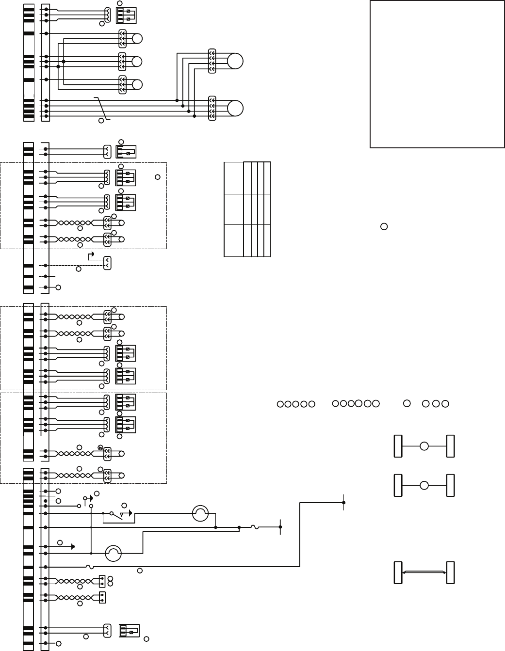
53
Troubleshooting: Wiring Schematic B (Alternate)
Use the wiring schematic on this
page for the following Electronic
Control Unit (ECU) part number:
K105303R000
See the previous page for a
second list of ECU part numbers.
If your ECU part number does
not appear on either list, please
call 1‑800‑AIR‑BRAKE, option 2,
and speak with the Tech Team.
FIGURE 24 - CAB WIRING SCHEMATIC FOR ECU LISTED ABOVE
16
16
3
4
20 ADDITIONAL AXLE WSS AND PMV INSTALLED PER EC-80 CONFIGURATION (6S/4M, 6S/6M).
21. ABS/ESP/TRAILER LAMP VIA J1939.
22. NO ABS OFF ROAD SWITCH. ABS OFF ROAD ACTIVATED WITH ATC MUD AND SNOW.
9
19 CAN SENSOR WIRING - 18 AWG (FOUR CONDUCTOR TWISTED WIRE REQUIRED).
HSA
DISABLE
SWITCH
5A
16
ATC
LAMP
1. RETARDER CONTROL VIA SAE J1939.
2 DIAGNOSTICS VIA SAE J1939.
3 MOMENTARY SWITCH.
4 ATC ENGINE CONTROL PER SAE J1939.
5 PRESSURE MODULATOR VALVE (PMV): BENDIX M-32, M-32QR, M-40X.
7 WHEEL SPEED SENSOR (WSS): BENDIX WS-24.
9 TRACTION CONTROL VALVE (TCV).
10 SERIAL COMMUNICATIONS - 18 AWG (TWISTED PAIR REQUIRED).
NOTES:
AA
8
19
CAN HI 2
CAN LO 2
J1939_LO
J1939_HI
BATTERY
ATC IND
GROUND
ADDITIONAL AXLE 20
11
16 TPMS WIRING - 3 WIRES.
17 POLE
18 POLE
15 POLE
WSS
DRIVE
AXLE
RIGHT
WSS
DRIVE
AXLE
LEFT
WSS
STEER
AXLE
RIGHT
IGNITION
HSA DISABLE
ATC DIS OR DIAG
SW
TPMS COMM
WSS_DR+
WSS_DR-
WSS_DL+
WSS_DL-
13 14 7816 17 13218 910 11 15 18
30A
WSS
STEER
AXLE
LEFT
HSA
SOL
PMV_DR_HLD
PMV_DR_REL
PMV_DR_CMN
PMV_DL_HLD
PMV_DL_REL
PMV_DL_CMN
PMV_SR_HLD
PMV_SR_REL
PMV_SR_CMN
PMV_SL_HLD
PMV_SL_REL
PMV_SL_CMN
9
TRACTION
CONTROL
VALV E
TPMS PWR
WSS_SR+
WSS_SR-
WSS_SL+
WSS_SL-
10 13
916 17
12 47612
31
11 14 58
WSS_AR+
WSS_AR-
WSS_AL+
WSS_AL-
HSA SOLENOID
PMV_AR_HLD
PMV_AR_REL
PMV_AR_CMN
TCV_SA_CMN
TCV_SA
12 15 11 14
23
5
810 13
9
WSS
ADD
AXLE
RIGHT
WSS
ADD
AXLE
LEFT
6
17. WHEN X1 IS DISCONNECTED FROM ECU, BODY CONTROLLER NEEDS TO ILLUMINATE ABS INDICATOR.
HSA
LAMP
6 PMV CONNECTOR TWIST-LOCK PACKARD
COMMON (CMN) PIN 2 PIN B
HOLD (HLD) PIN 3 PIN C
RELEASE (REL) PIN 1 PIN A
8 WSS WIRING - 18 AWG (TWISTED PAIR REQUIRED).
18
18 STOP LAMP SWITCH INPUT REQUIRED FOR ATC AND ALL-WHEEL DRIVE VEHICLES.
IS PROVIDED VIA STOP LAMP SWITCH VIA J1939 COMMUNICATION.
12
6 6 6
5 5 5
7 7
77
7
15
IND. INTERLOCK
7
2
X2
X2
X3
X3
8
1010 88 8 8
X1
X1
11 DOTTED LINES: SPECIAL FUNCTION (OPTIONS).
X1
X2
X3
15. PRODUCT SPECIFICATION: Y119679 AND Y173755.
14. ALL WIRE IS CONDUCTOR CROSS-SECTION OF 16 AWG, UNLESS OTHERWISE NOTED.
321 321 321 321
6
5
5
DRIVE
AXLE
RIGHT
PMV
DRIVE
AXLE
LEFT
PMV
STEER
AXLE
LEFT
PMV
STEER
AXLE
RIGHT
PMV
321
ADD
AXLE
RIGHT
PMV
12 BATTERY AND GROUND - 12 AWG.
+12V IGNITION
8-968974-1
8-968973-1
DRIVE AXLE STEER AXLE
17
12
13. ALL WHEEL DRIVE VEHICLES ONLY. REQUIRES STOP LAMP INPUT (SEE NOTE 18 ).
1718091-1
AMP
CONNECTOR
PART NUMBER
REF. NO. NUMBER OF
CONTACTS
WIRE HARNESS CONNECTORS
10
8
711 3
12
4
5
NOT CONNECTED
TRAC
CONTROL
VALV E
(TCV)
TCV_DA
TCV_DA_CMN
54
+12V BATTERY
ADDITIONAL
R
L
VEHICLE 6 X 4
R
L
STEER
SA
DRIVE
DA
TPMS GND
6
X4
X4
12
STEER
AXLE
PS_CMN
PS_SIG 1
PS_SIG 3
PS_SPL
PS_SIG 2
CAN_SEN_LO
CAN_SEN_HI
CAN_SEN_CMN
CAN_SEN_SPL
PMV_AL_HLD
PMV_AL_REL
PMV_AL_CMN
47
6
6
32 1
5
PRESSURE
SENSOR 1
(PRIMARY
DELIVERY)
PRESSURE
SENSOR 3
(SUSPENSION)
PRESSURE
SENSOR 2
(SECONDARY
DELIVERY)
YAW
RATE
SENSOR
6
X4 12 POLE 8-968972-1
PMV_TR_HLD
PMV_TR_REL
PMV_TR_CMN
612 9
321
PMV
TRAILER
ADD
AXLE
LEFT
PMV
5
ATC DISABLE
OR
DIAGNOSTIC
SWITCH
ATC
MUD
& SNOW
3
I/0
54
ABS — Antilock Brake System.
ABS Event — Impending wheel lock situation that causes the
ABS Controller to activate the modulator valve(s).
ABS Indicator Lamp — An amber lamp which indicates the
operating status of an antilock system. When the indicator lamp
is on, ABS is disabled and the vehicle reverts to normal brake
operation.
Air Gap — Distance between the Sensor and tone ring.
ASR — Automatic Slip Regulation. Another name for traction
control.
ATC — Automatic Traction Control. An additional ABS function
in which engine torque is controlled and brakes are applied
differentially to enhance vehicle traction.
ATC/ESP Lamp — A lamp that indicates when stability functions,
including traction control, roll stability program or yaw control
are operating.
Channel — A controlled wheel site.
CAN — Controller Area Network. J1939 is an SAE version of
the CAN link.
Clear Codes — System to erase historical Diagnostic Trouble
Codes (DTCs) from the ECU, from either the Diagnostic Switch
or from a hand‑held diagnostic tool (only repaired DTCs may
be cleared).
Conguration — The primary objective is to identify a “normal”
set of sensors and modulators for the Electronic Control Unit,
so that it will identify future missing sensors and modulators.
Diagnostic Connector — Diagnostic receptacle in vehicle cab
for connection of J1939 hand‑held or PC based test equipment.
The tester can initiate test sequences, and can also read system
parameters.
Diagnostic Switch — A switch used to activate blinks codes.
Differential Braking — Application of brake force to a spinning
wheel so that torque can be applied to wheels which are not
slipping.
ECU — Electronic Control Unit.
ESP — Electronic Stability Program. Full stability function that
includes RSP & YC subfunctions.
Diagnostic Trouble Code — A condition that interferes with the
generation or transmission of response or control signals in the
vehicle's ABS system that could lead to the functionality of the
ABS system becoming inoperable in whole or in part.
FMVSS-121 — Federal Motor Vehicle Safety Standard which
regulates air brake systems.
Hill Start (or “Hill Start Assist”) HS/HSA — This feature
interfaces between the transmission and braking system to help
the driver prevent the vehicle from rolling downhill when moving
up a steep incline from a stationary position.
IR — Independent Regulation. A control method in which a
wheel is controlled at optimum slip, a point where retardation
and stability are maximized. The brake pressure that is best
for the wheel in question is directed individually into each brake
chamber.
J1939 — A high speed data link used for communications
between the ABS ECU engine, transmission and retarders.
LAS — Lateral Acceleration Sensor.
MIR — Modied Independent Regulation. A method of controlling
the opposite sides of a steer axle during ABS operation so that
torque steer and stopping distance are minimized.
PLC — Power Line Carrier. The serial communication protocol
used to communicate with the trailer over the blue full time
power wire.
PMV — Pressure Modulator Valve. An air valve which is used
to vent or block air to the brake chambers to limit or reduce
brake torque.
QR — Quick Release. Quick release valves allow faster release
of air from the brake chamber after a brake application. To
balance the system, quick release valves have hold off springs
that produce higher crack pressures (when the valves open).
Relay Valve — Increases the application speed of the service
brake. Installed near brakes with larger air chambers (type 24
or 30). The treadle valve activates the relay valve with an air
signal. The relay valve then connects its supply port to its delivery
ports. Equal length air hose must connect the delivery ports of
the relay valve to the brake chambers.
Retarder Relay — A relay which is used to disable a retarder
when ABS is triggered.
RSP — Roll Stability Program. An all‑axle ABS solution that
helps reduce vehicle speed by applying all vehicle brakes as
needed, reducing the tendency to roll over.
SAS — Steering Angle Sensor.
Sensor Clamping Sleeve — A beryllium copper sleeve which
has ngers cut into it. It is pressed between an ABS sensor and
mounting hole to hold the sensor in place.
Stored Diagnostic Trouble Codes — A DTC that occurred in
the past.
TCS — Traction Control System, another name for ATC or ASR.
TCV — Traction Control Valve.
Tone Ring — A ring that is usually pressed into a wheel hub that
has a series of teeth (usually 100) and provides actuation for the
speed sensor. Note maximum run out is .008.
YC — Yaw Control. Helps stabilize rotational dynamics of vehicle.
YRS — Yaw Rate Sensor.
GLOSSARY
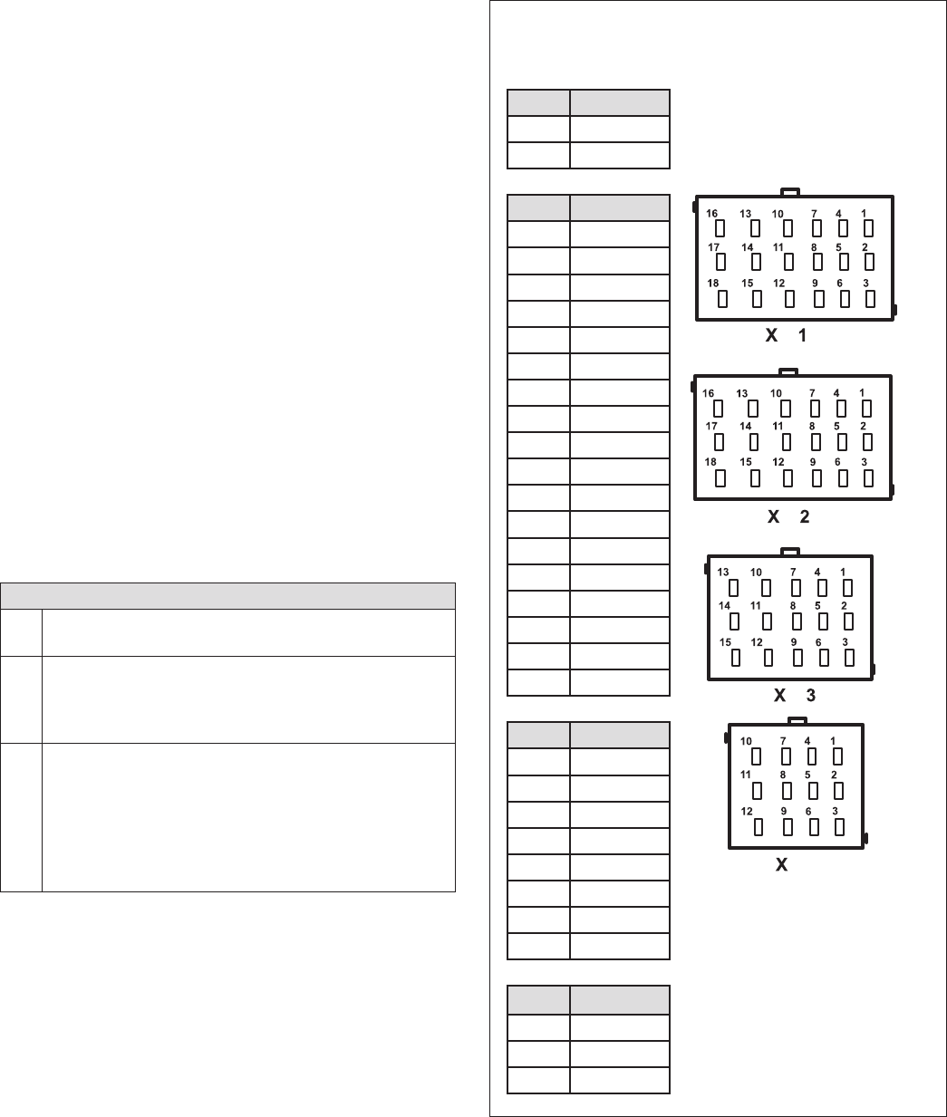
55
APPENDIX A: TROUBLESHOOTING A 12-7 BLINK CODE, EQUIVALENT TO A
(SID-93 FMI-4) (SPN-0802 FMI-04) DIAGNOSTIC TROUBLE CODE (DTC)
Bendix® EC-80™ ESP® Electronic Control Unit (ECU)
1) Remove the X1, X2, X3 and X4 connectors from the ECU.
2) Using X1‑1 as the ground connection, check for resistance
for the entire X2 connector. There should be no resistance
to ground found. Please ll out worksheet on this page.
3) Using X1‑1 as the ground connection, check for resistance
for X1‑4 and X1‑5. There should be no resistance to ground.
4) Using X1‑1 as the ground connection, check for resistance for
X3‑4, X3‑6, X3‑7, X3‑9, X3‑10, X3‑13, X3‑3 and X3‑5. There
should be no resistance to ground. (Even if the vehicle is not
congured for 6S/6M).
5) Using X1‑1 as the ground connection, check for resistance
for X4‑6, X4‑9 and X4‑12. There should be no resistance to
ground.
6) Troubleshoot any pin that has resistance to ground. If no
issues are found continue to step 7.
7) Reconnect the X1 connector only and apply IGN power to the
ECU and using the DTC screen of Bendix® ACom® Diagnostic
Software, clear all DTCs. Re‑check for any DTCs. If the
12‑7 DTC is still present, the problem is the Traction Solenoid
Wiring or Solenoid.
8) If the 12‑7 DTC does not reappear, remove power and connect
the X2 connector, reapply power, then clear all DTCs. If the
12‑7 DTC is no longer present, connect the X3 connector
and clear all DTCs.
9) If at this point the 12‑7 DTC is not present, the problem is
with the X4 connector.
For Peterbilt® & Kenworth® Trucks Only:
10) Clear all DTCs. If the 12‑7 DTC reappears, the issue is
on the X4 connector. Otherwise, proceed to the next step.
11) Disconnect all modulators and the traction solenoid.
Clear all DTCs. If the DTC does not reappear, connect
one modulator and Traction Solenoid at a time, until the
DTC reappears. Otherwise, continue to the next step.
12) Make sure all modulators and the traction solenoid are
connected. Disconnect the ABS bulkhead connector at
the engine (top‑left side) and remove Pins 1, 2, 11 &12.
Reconnect the connector and apply IGN power to the
ECU. Using Bendix ACom Diagnostics, clear all DTCs.
If the 12‑7 DTC returns, the problem is either the wiring
harness inside the cab or the ECU.
Record Resistances
Below:
X1-1 for ground point
X1 Pin Resistance
X1‑4
X1‑5
X2 Pin Resistance
X2‑1
X2‑2
X2‑3
X2‑4
X2‑5
X2‑6
X2‑7
X2‑8
X2‑9
X2‑10
X2‑11
X2‑12
X2‑13
X2‑14
X2‑15
X2‑16
X2‑17
X2‑18
X3 Pin Resistance
X3‑4
X3‑5
X3‑6
X3‑7
X3‑8
X3‑9
X3‑10
X3‑13
X4 Pin Resistance
X4‑6
X4‑9
X4‑12
4

56
APPENDIX B: J1939 SPN AND FMI CODES AND THEIR BENDIX
®
BLINK CODE EQUIVALENTS
SPN
(J1939) FMI
(J1939)
Bendix® Blink Code
Equivalent(s) Diagnostic Trouble Code (DTC) Description Lamp Status
(1st
Digit) (2nd
Digit) ABS ATC/
ESP
‑ 1 1 No DTCs ‑ ‑
Power Supply DTCs
168 3 6 2 Battery Voltage Too High ON ON
168 4 6 1 Battery Voltage Too Low ON ON
Miscellaneous DTCs
564 3 25 3 Differential Lock Solenoid Shorted To Voltage ON ON
564 4 25 2 Differential Lock Solenoid Shorted To Ground ON ‑
564 5 25 1 Differential Lock Solenoid Open ON ‑
564 13 25 7 Output Conguration Error ‑ Differential ON ‑
575 14 12 17 ABS Disabled Due To Special Mode Or Off‑Road ABS Active.
Note: The ABS warning lamp will be ashing indicating the is in ABS off-
road mode ‑ ON
576 14 12 3 ATC or ESP Disabled or Dynamometer Test Mode Active ON ‑
614 3 12 32 I/O 2 or 3 Shorted High (EC‑80 ATC) OR
I/O 2 or 3 Shorted High or Stop Lamp Output Error (ESP EC‑80) ‑ ON
614 3 25 6 I/O 3 Shorted to Voltage ‑ ON
614 4 25 5 I/O 3 Shorted to Ground ‑ ON
614 5 25 4 I/O 3 Open Circuit ‑ ON
614 13 25 8 Output Conguration Error ‑ I/O 3 ‑ ON
615 14 12 19 Maximum Number of Pressure Modulator Valve (PMV) Cycles Exceeded ‑ ‑
615 14 12 20 Maximum Number of Traction Control Valve (TCV) Cycles Exceeded ‑ ‑
614 3 12 32 I/O 2 or 3 Shorted High (EC‑80 ATC) OR
I/O 2 or 3 Shorted High or Stop Lamp Output Error (ESP EC‑80) ‑ ON
614 3 25 6 I/O 3 Shorted to Voltage ‑ ON
614 4 25 5 I/O 3 Shorted to Ground ‑ ON
614 5 25 4 I/O 3 Open Circuit ‑ ON
614 13 25 8 Output Conguration Error ‑ I/O 3 ‑ ON
615 14 12 19 Maximum Number of PMV Cycles Exceeded ‑ ‑
615 14 12 20 Maximum Number of TCV Cycles Exceeded ‑ ‑
ECU DTCs (Also see other 629 codes)
629 2 13 4 ECU DTC (2678C) ON ON
629 2 13 5 ECU DTC (1C) ON ON
629 2 13 7 Conguration Mismatch ON ON
629 2 13 17 ECU DTC (C8C) ON ON
Miscellaneous DTCs
629 8 12 29 Air System / Mechanical Component ON ON
ECU DTCs (Also see other 629 codes)
629 12 13 3 ECU DTC (10) ON ON
629 12 13 14 ECU DTC (C6) ON ON
629 12 13 15 ECU DTC (CF) ON ON
629 12 13 16 ECU DTC (C0) ON ON
Miscellaneous DTCs
629 14 12 28 Air System / Mechanical Component ON ON
629 14 12 30 ESP Disabled Due to Off‑Road Mode ‑ ON

57
APPENDIX B: J1939 SPN AND FMI CODES AND THEIR BENDIX
®
BLINK CODE EQUIVALENTS
SPN
(J1939) FMI
(J1939)
Bendix® Blink Code
Equivalent(s) Diagnostic Trouble Code (DTC) Description Lamp Status
(1st
Digit) (2nd
Digit) ABS ATC/
ESP
ECU DTCs (Also see other 629 codes)
629 14 13 1 ECU DTC (5FC) ON ON
630 12 13 6 ECU DTC(6CD) ON ON
630 12 13 10 ECU DTC (5F3) ON ON
630 12 13 19 ECU DTC (63) ‑ ‑
630 12 13 20 ECU DTC (6E) ON ON
630 12 13 28 ECU DTC (7CD) ON ON
630 13 13 2 ECU DTC (5CD) ON ON
630 13 13 8 ECU DTC (56) ON ON
630 13 13 9 ECU DTC (CA3C) ON ON
630 13 13 18 ECU DTC (CC) ON ON
630 13 13 21 ECU DTC (6C) ON ON
630 13 13 22 ECU DTC (63C) ON ON
630 13 13 25 VIN Mismatch ‑ ON
630 13 13 26 Valve Conguration Mismatch ‑ ON
630 13 13 29 ECU DTC (5D) ON ON
630 14 13 13 Conguration Mismatch ON ON
J1939 DTCs
639 2 11 2 J1939 Electronic Retarder Time‑out or Invalid Signal ON ON
639 2 11 3 J1939 Electronic Engine Controller 1 Time‑out or Invalid Signal ‑ ON
639 2 11 4 J1939 Electronic Engine Controller 2 Time‑out or Invalid Signal ‑ ON
639 2 11 5 J1939 AIR Message Time‑out or Invalid Signal ‑ ON
639 2 11 6 ESP J1939 CAN Message Time‑out ‑ ON
639 2 11 7 Time‑out or Invalid CAN Data for ETC7/VP15 ‑ ‑
639 2 11 8 Time‑out or Invalid Data on XBR ‑ ‑
639 2 11 10 J1939 Electronic Transmission Controller 1 Time‑out or Invalid Signal ON ‑
639 2 11 11 AUXIO CAN Message Time‑out ‑ ‑
639 2 11 12 J1939 Hill Start Aid Switch Signal Not Available ‑ HSA LAMP ON ‑ ‑
639 2 11 14 J1939 CAN Message Related to ESP is Incomplete ‑ ON
639 2 11 15 J1939 Electronic Engine Controller 3 Time‑out or Invalid Signal ‑ ON
639 2 11 16 J1939 Electronic Transmission Controller 2 Time‑out ‑ ON
639 2 11 20 J1939 EAC1 Time‑out or Invalid Signal ‑ ON
639 2 11 21 CAN Message CGW_C1 Time‑out or Invalid Signal ‑ ON
639 2 11 22 CAN Message ASC1_CLCS Time‑out or Invalid Signal ‑ ON
639 2 11 23 J1939 CCVS Time‑out or Invalid Signal ‑ ON
639 2 11 24 J1939 TCO(Tachograph) Time‑out ‑ ON
639 2 11 28 J1939 Proprietary XBR Message Out‑of‑Range ‑ ON
639 2 26 1 J1939 CAN Time‑out of ESP Message ‑ ON
639 2 26 2 Time‑out or Invalid CAN Data – CCVS 2 ESP Message ‑ ON
639 2 26 3 Time‑out or Invalid CAN Data – Electronic Engine Controller 1 ESP
Message ‑ ON
639 2 26 4 Time‑out or Invalid CAN Data – EEC2 ESP Message ‑ ON
639 2 26 5 Time‑out or Invalid CAN Data – Driveline Line Retarder ESP Message ‑ ON
639 2 26 6 Time‑out or Invalid CAN Data – Engine Retarder ESP Message ‑ ON
639 2 26 7 Time‑out or Invalid CAN Data – Exhaust Retarder ESP Message ‑ ON
639 2 26 8 Time‑out or Invalid CAN Data – PROP XBR ESP Message ‑ ON
639 2 26 9 Time‑out or Invalid CAN Data – Transmission Retarder ESP Message ‑ ON
639 2 26 10 Time‑out or Invalid CAN Data – Electronic Transmission Controller 1 ESP
Message ‑ ON
639 2 26 11 Time‑out or Invalid AUX I/O – ESP Message ‑ ON
639 2 26 12 Time‑out or Invalid Data for Conguration of Electronic Engine Controller 1
ESP Message ‑ ON

58
APPENDIX B: J1939 SPN AND FMI CODES AND THEIR BENDIX
®
BLINK CODE EQUIVALENTS
SPN
(J1939) FMI
(J1939)
Bendix® Blink Code
Equivalent(s) Diagnostic Trouble Code (DTC) Description Lamp Status
(1st
Digit) (2nd
Digit) ABS ATC/
ESP
639 2 26 13 Invalid Data Transfer Time‑out of EC1 ESP Message ‑ ON
639 2 26 14 Time‑out or Invalid Data for Conguration of Driveline Line Retarder ESP
Message ‑ ON
639 2 26 15 Time‑out or Invalid CAN Data – Electronic Engine Controller ESP Message ‑ ON
639 2 26 16 Time‑out or Invalid CAN Data – Electronic Transmission Controller 2‑
Message Required for ESP ‑ ON
639 2 26 17 Time‑out or Invalid Data for Conguration of Engine Retarder ESP Message ‑ ON
639 2 26 18 Time‑out or Invalid Data for Conguration of Exhaust Retarder ESP
Message ‑ ON
639 2 26 19
Time‑out or Invalid Data for Conguration of Transmission Retarder ESP Message
‑ ON
639 2 26 20 Invalid Data Transfer Time‑out of Driveline Line Retarder ESP Message ‑ ON
639 2 26 21 Invalid Data Transfer Time‑out of Engine Retarder ESP Message ‑ ON
639 2 26 22 Invalid Data Transfer Time‑out of Exhaust Retarder ESP Message ‑ ON
639 2 26 23 Time‑out or Invalid CAN Data – CCVS ESP Message ‑ ON
639 2 26 24 Time‑out or Invalid CAN Data – TCO ESP Message ‑ ON
639 2 26 25 Invalid Data Transfer Time‑out of Driveline Line Retarder ESP Message ‑ ON
639 2 26 26 ESP Related CM3 Time‑out at J1939 ‑ ON
639 2 26 27 Time‑out of message or Invalid Data Received from Transmission Transfer
information on J1939 ‑ Message Required for ESP ‑ ON
639 2 26 28 Time‑out or Invalid CAN Data – Electronic Axle Controller 1ESP Message ‑ ON
639 5 11 29 J1939 CAN Messages Are Not Being Transmitted / Received ON ON
639 12 11 1 J1939 Serial Link ON ON
Wheel Speed Sensor DTCs
789 1 2 1 Steer Axle Left WSS Excessive Air Gap ON ON
789 2 2 3 Steer Axle Left WSS Open or Shorted ON ON
789 7 2 5 Steer Axle Left WSS Wheel End ON ON
789 8 2 6 Steer Axle Left Erratic Sensor Signal ON ON
789 9 2 2 Steer Axle Left WSS Signal Low at Drive Off ON ON
789 10 2 4 Steer Axle Left WSS Loss of Sensor Signal ON ON
789 13 2 7 Steer Axle Left WSS Tire Size Calibration ON ON
790 1 3 1 Steer Axle Right WSS Excessive Air Gap ON ON
790 2 3 3 Steer Axle Right WSS Open or Shorted ON ON
790 7 3 5 Steer Axle Right WSS Wheel End ON ON
790 8 3 6 Steer Axle Right Erratic Sensor Signal ON ON
790 9 3 2 Steer Axle Right WSS Signal Low at Drive Off ON ON
790 10 3 4 Steer Axle Right WSS Loss of Sensor Signal ON ON
790 13 3 7 Steer Axle Right WSS Tire Size Calibration ON ON
791 1 4 1 Drive Axle Left WSS Excessive Air Gap ON ON
791 2 4 3 Drive Axle Left WSS Open or Shorted ON ON
791 7 4 5 Drive Axle Left WSS Wheel End ON ON
791 8 4 6 Drive Axle Left Erratic Sensor Signal ON ON
791 9 4 2 Drive Axle Left WSS Signal Low at Drive Off ON ON
791 10 4 4 Drive Axle Left WSS Loss of Sensor Signal ON ON
791 13 4 7 Drive Axle Left Tire Size Calibration ON ON
792 1 5 1 Drive Axle Right WSS Excessive Air Gap ON ON
792 2 5 3 Drive Axle Right WSS Open or Shorted ON ON
792 7 5 5 Drive Axle Right WSS Wheel End ON ON
792 8 5 6 Drive Axle Right Erratic Sensor Signal ON ON
792 9 5 2 Drive Axle Right WSS Signal Low at Drive Off ON ON
792 10 5 4 Drive Axle Right WSS Loss of Sensor Signal ON ON
792 13 5 7 Drive Axle Right Tire Size Calibration ON ON
793 1 14 1 Additional Axle Left WSS Excessive Air Gap ON ON

59
APPENDIX B: J1939 SPN AND FMI CODES AND THEIR BENDIX
®
BLINK CODE EQUIVALENTS
SPN
(J1939) FMI
(J1939)
Bendix® Blink Code
Equivalent(s) Diagnostic Trouble Code (DTC) Description Lamp Status
(1st
Digit) (2nd
Digit) ABS ATC/
ESP
793 2 14 3 Additional Axle Left WSS Open or Shorted ON ON
793 7 14 5 Additional Axle Left WSS Wheel End ON ON
793 8 14 6 Additional Axle Left Erratic Sensor Signal ON ON
793 9 14 2 Additional Axle Left WSS Signal Low at Drive Off ON ON
793 10 14 4 Additional Axle Left WSS Loss of Sensor Signal ON ON
793 13 14 7 Additional Axle Left Tire Size Calibration ON ON
794 1 15 1 Additional Axle Right WSS Excessive Air Gap ON ON
794 2 15 3 Additional Axle Right WSS Open or Shorted ON ON
794 7 15 5 Additional Axle Right WSS Wheel End ON ON
794 8 15 6 Additional Axle Right Erratic Sensor Signal ON ON
794 9 15 2 Additional Axle Right WSS Signal Low at Drive Off ON ON
794 10 15 4 Additional Axle Right WSS Loss of Sensor Signal ON ON
794 13 15 14 Additional Axle Right Tire Size Calibration ON ON
Pressure Modulator Valve (PMV) DTCs
795 5 7 7 Steer Axle Left PMV Common Open Circuit ON ON
795 13 7 8 Steer Axle Left PMV Conguration Error ON ON
796 5 8 7 Steer Axle Right PMV Common Open ON ON
796 13 8 8 Steer Axle Right PMV Conguration Error ON ON
797 5 9 7 Drive Axle Left PMV Common Open Circuit ON ON
797 13 9 8 Drive Axle Left PMV Conguration Error ON ON
798 5 10 7 Drive Axle Right PMV Common Open Circuit ON ON
798 13 10 8 Drive Axle Right PMV Conguration Error ON ON
799 5 16 7 AA Left PMV Common Open Circuit ON ON
799 13 16 8 AA Left PMV Conguration Error ON ON
800 5 17 7 Additional Axle Right PMV Common Open Circuit ON ON
800 13 17 8 AA Right PMV Conguration Error ON ON
Miscellaneous DTCs
801 2 12 4 Retarder Relay Open Circuit or Shorted to Ground ON ‑
801 3 12 5 Retarder Relay Open Circuit or Shorted to Voltage ON ‑
Pressure Modulator Valve (PMV) DTCs
802 3 12 8 PMV Common Shorted to Voltage ON ON
802 4 12 7 PMV Commons Shorted to Ground ON ON
Miscellaneous DTCs
802 12 13 11 ECU DTC (F1A) ON ON
802 12 13 12 ECU DTC (F14) ON ‑
805 14 12 9 ATC Disabled to Prevent Brake Fade - -
Traction Control Valve (TCV) DTCs
806 3 18 2 TCV DA Solenoid Shorted to Voltage ON ON
806 4 18 1 TCV DA Solenoid Shorted to Ground ‑ ON
806 5 18 3 TCV DA Solenoid Open Circuit ‑ ON
806 13 18 4 TCV DA Valve Conguration Error ON ON
807 3 19 2 TCV SA Solenoid Shorted to Voltage ‑ ON
807 4 19 1 TCV SA Solenoid Shorted to Ground ‑ ON
807 5 19 3 TCV SA Solenoid Open Circuit ON ON
807 13 19 4 TCV SA Valve Conguration Error ON ON
Miscellaneous DTCs
810 7 12 11 Wheel Speed Sensors Reversed on an Axle ON ON
811 2 12 6 ABS Dash Indicator Circuit DTC ON ‑
811 13 12 38 Warning Lamp Ground Pin Connected to GND in Conict with Conguration
Settings ON ‑
815 13 14 10 Additional Axle WSS Conguration Error ON ON

60
APPENDIX B: J1939 SPN AND FMI CODES AND THEIR BENDIX
®
BLINK CODE EQUIVALENTS
SPN
(J1939) FMI
(J1939)
Bendix® Blink Code
Equivalent(s) Diagnostic Trouble Code (DTC) Description Lamp Status
(1st
Digit) (2nd
Digit) ABS ATC/
ESP
Pressure Modulator Valve (PMV) DTCs
932 3 7 5 Steer Axle Left PMV Hold Solenoid Shorted to Voltage ON ON
932 4 7 4 Steer Axle Left PMV Hold Solenoid Shorted to Ground ON ON
932 5 7 6 Steer Axle Left PMV Hold Solenoid Open Circuit ON ON
933 3 8 5 Steer Axle Right PMV Hold Solenoid Shorted to Voltage ON ON
933 4 8 4 Steer Axle Right PMV Hold Solenoid Shorted to Ground ON ON
933 5 8 6 Steer Axle Right PMV Hold Solenoid Open Circuit ON ON
934 3 9 5 Drive Axle Left PMV Hold Solenoid Shorted to Voltage ON ON
934 4 9 4 Drive Axle Left PMV Hold Solenoid Shorted to Ground ON ON
934 5 9 6 Drive Axle Left PMV Hold Solenoid Open Circuit ON ON
935 3 10 5 Drive Axle Right PMV Hold Solenoid Shorted to Voltage ON ON
935 4 10 4 Drive Axle Right PMV Hold Solenoid Shorted to Ground ON ON
935 5 10 6 Drive Axle Right PMV Hold Solenoid Open Circuit ON ON
936 3 16 5 AA Left PMV Hold Solenoid Shorted to Voltage ON ON
936 4 16 4 AA Left PMV Hold Solenoid Shorted to Ground ON ON
936 5 16 6 AA Left PMV Hold Solenoid Open Circuit ON ON
936 13 16 11 Output Conguration Error ‑ Left Additional Axle Hold ON ON
937 3 17 5 AA Right PMV Hold Solenoid Shorted to Voltage ON ON
937 4 17 4 AA Right PMV Hold Solenoid Shorted to Ground ON ON
937 5 17 6 AA Right PMV Hold Solenoid Open Circuit ON ON
937 13 17 11 Output Conguration Error ‑ Additional Axle Right Hold ON ON
938 3 7 2 Steer Axle Left PMV Release Solenoid Shorted to Voltage ON ON
938 4 7 1 Steer Axle Left PMV Release Solenoid Shorted to Ground ON ON
938 5 7 3 Steer Axle Left PMV Release Solenoid Open Circuit ON ON
939 3 8 2 Steer Axle Right PMV Release Solenoid Shorted to Voltage ON ON
939 4 8 1 Steer Axle Right PMV Release Solenoid Shorted to Ground ON ON
939 5 8 3 Steer Axle Right PMV Release Solenoid Open ON ON
940 3 9 2 Drive Axle Left PMV Release Solenoid Shorted to Voltage ON ON
940 4 9 1 Drive Axle Left PMV Release Solenoid Shorted to Ground ON ON
940 5 9 3 Drive Axle Left PMV Release Solenoid Open Circuit ON ON
941 3 10 2 Drive Axle Right PMV Release Solenoid Shorted to Voltage ON ON
941 4 10 1 Drive Axle Right PMV Release Solenoid Shorted to Ground ON ON
941 5 10 3 Drive Axle Right PMV Release Solenoid Open Circuit ON ON
942 3 16 2 AA Left PMV Release Solenoid Shorted to Voltage ON ON
942 4 16 1 AA Left PMV Release Solenoid Shorted to Ground ON ON
942 5 16 3 AA Left PMV Release Solenoid Open Circuit ON ON
942 13 16 10 Output Conguration Error ‑ Additional Axle Left Release ON ON
943 3 17 2 AA Right PMV Release Solenoid Shorted to Voltage ON ON
943 4 17 1 AA Right PMV Release Solenoid Shorted to Ground ON ON
943 5 17 3 AA Right PMV Release Solenoid Open Circuit ON ON
943 13 17 10 Output Conguration Error ‑ Additional Axle Right Release ON ON
Miscellaneous DTCs
1043 2 12 14 ESP sensor supply too high or too Low ‑ ON
1043 2 12 22 U‑ Bat too high or too Low for ESP sensor ‑ ON
1045 2 12 2 Stop Light Switch Defective ON ON
1045 2 12 27 Brake Lamp Input Mismatch With Brake Lamp Output ON ON
1045 7 12 1 Stop Lamp Switch Not Detected ‑ ON

61
APPENDIX B: J1939 SPN AND FMI CODES AND THEIR BENDIX
®
BLINK CODE EQUIVALENTS
SPN
(J1939) FMI
(J1939)
Bendix® Blink Code
Equivalent(s) Diagnostic Trouble Code (DTC) Description Lamp Status
(1st
Digit) (2nd
Digit) ABS ATC/
ESP
Pressure Modulator Valve (PMV) DTCs
1056 3 20 2 Trailer PMV: Release Solenoid Shorted to Voltage ON ON
1056 3 20 5 Trailer PMV: hold Solenoid Shorted to Voltage ON ON
1056 4 20 1 Trailer PMV: Release Solenoid Shorted to Ground ‑ ON
1056 4 20 4 Trailer PMV: hold Solenoid Shorted to Ground ‑ ON
1056 5 20 3 Trailer PMV: Release Solenoid Open Circuit ‑ ON
1056 5 20 6 Trailer PMV: hold Solenoid Open Circuit ‑ ON
1056 5 20 7 Trailer PMV: Common Open Circuit ‑ ON
1056 13 20 8 Trailer PMV: Conguration Error ‑ ON
Brake Demand/Load Sensor DTCs
1059 2 24 3 PS3 Open or Shorted ‑ ON
1067 2 24 1 PS1 Open or Shorted ‑ ON
1067 3 24 5 PS Supply Voltage High Error ‑ ON
1067 4 24 7 PS Supply Voltage Low Error ‑ ON
1067 6 24 8 PS Supply Voltage Error ‑ ON
1067 7 24 6 PS Not Calibrated ‑ ON
1067 11 24 4 (PS1/PS2 Plausibility Error) Brake Demand Primary and Secondary Circuit
Pressure Sensor Plausibility Error ‑ ON
1067 14 24 9 Pressure Sensor not congured. ‑ ON
1068 2 24 2 PS2 Open or Shorted ‑ ON
Miscellaneous DTCs
1238 14 12 37 ATC disable by switch ‑ ‑
Steering Angle Sensor DTCs
1807 2 21 3 SAS Static Signal ‑ ON
1807 2 21 4 SAS Signal Out of Range ‑ ON
1807 2 21 5 SAS Signal Reversed ‑ ON
1807 2 21 7 SAS Gradient Error ‑ ON
1807 2 21 9 SAS Long Term Calibration Error ‑ ON
1807 2 21 10 SAS Plausibility Check (Ref YAW Rate) ‑ ON
1807 9 21 8 SAS CAN Time‑out ‑ ON
1807 12 21 6 SAS Signal Invalid ‑ ON
1807 13 21 1 SAS Not Calibrated ‑ ON
1807 13 21 2 SAS Calibration in Progress ‑ ON
1807 13 21 11 SAS Detected But Not Congured ‑ ON
Yaw Rate Sensor DTCs
1808 2 22 1 YRS Signal Out of Range ‑ ON
1808 2 22 2 YRS Reversed Signal ‑ ON
1808 2 22 3 YRS Invalid Signal ‑ ON
1808 2 22 4 YRS Gradient Error ‑ ON
1808 2 22 6 YRS Static BITE Error ‑ ON
1808 2 22 7 YRS Dynamic BITE Error ‑ ON
1808 2 22 8 YRS Fast Calibration Error ‑ ON
1808 2 22 9 YRS Static Calibration Error ‑ ON
1808 2 22 10 YRS Normal Calibration Error ‑ ON
1808 2 22 12 YRS Plausibility Check (Ref Yaw Rate) ‑ ON
1808 2 22 13 YRS Plausibility Error (Inside Model Based Limits) ‑ ON
1808 2 22 14 YRS Plausibility Error (Outside Model Based Limits) ‑ ON
1808 2 22 16 YRS Vibration Detected ‑ ON
1808 9 22 5 YRS CAN Time‑out ‑ ON
1808 13 22 17 YRS Detected But Not Congured ‑ ON
1808 14 23 7 Erratic ESP Signal ‑ ON

62
APPENDIX B: J1939 SPN AND FMI CODES AND THEIR BENDIX
®
BLINK CODE EQUIVALENTS
SPN
(J1939) FMI
(J1939)
Bendix® Blink Code
Equivalent(s) Diagnostic Trouble Code (DTC) Description Lamp Status
(1st
Digit) (2nd
Digit) ABS ATC/
ESP
Lateral Acceleration Sensor DTCs
1809 2 23 1 LAS Signal of Range ‑ ON
1809 2 23 3 LAS Static Calibration Error ‑ ON
1809 2 23 4 LAS Long Term Calibration Error ‑ ON
1809 2 23 5 LAS Plausibility Error (Inside Model Based Limits) ‑ ON
1809 2 23 6 LAS Plausibility Error (Outside Model Based Limits) ‑ ON
1809 13 22 15 YRS‑ SAS Signal Cross‑Check Incomplete ‑ ON
1809 13 23 2 LAS Calibration in Progress ‑ ON
Miscellaneous
2011 31 11 26 ABS ECU CAN Address Conict ON ‑
2051 31 11 27 TPMS ECU CAN Address Conict ‑ TPMS INDICATOR LAMP ON ‑ ‑
HS/HSA Hill Start Feature DTCs
2622 2 12 24 HSA lamp Open Circuit or Shorted to GND ON ‑
2622 3 12 26 HSA valve: Solenoid Shorted to Voltage ON ‑
2622 3 12 31 HSA lamp Shorted to Voltage ON ON
2622 4 12 25 HSA valve: Solenoid Shorted to Ground ‑ ‑
2622 5 12 33 HSA valve: Solenoid Open Circuit ‑ ‑
Bendix® eTrac™ DTCs
2984 3 12 34 Bendix® eTrac™ Solenoid Shorted to Voltage ‑ ON
2984 4 12 35 Bendix eTrac Solenoid Shorted to Ground ‑ ON
Figures Used
Figure 1 - Bendix® ESP® EC‑80™ Controller ....................................................................1
Figure 2 - Bendix® WS‑24™ Wheel Speed Sensors .........................................................3
Figure 3 - Example Of A Bendix® M‑40X™ Modulator .....................................................3
Figure 4 - Examples Of Steering Angle Sensors ............................................................3
Figure 5 - Yaw And Brake Demand/Load Sensors ..........................................................4
Figure 6 - Additional Valves Necessary For The Hill Start Feature .................................4
Figure 7 - Bendix ESP EC‑80 Controller Features ..........................................................5
Figure 8 - Power Line Without PLC Signal ......................................................................5
Figure 9 - Power Line With PLC Signal ...........................................................................5
Figure 10 - Bendix ESP EC‑80 Controller Indicator Lamp Behavior ...............................8
Figure 11 - Vehicle Orientation (Typical) .........................................................................9
Figure 12 - RSP Example .............................................................................................. 12
Figure 13 - Yaw Control Example ..................................................................................12
Figure 14 - Typical Vehicle Diagnostic Connector Locations (J1939) ...........................21
Figure 15 - Example Of Blink Code Message ...............................................................21
Figure 16 - Diagnostic Modes........................................................................................22
Figure 17 - System Conguration Check .......................................................................23
Figure 18 - Bendix® ACom® Diagnostics .......................................................................24
Figure 19 - The Bendix® Remote Diagnostic Unit..........................................................24
Figure 20 - Diagnostic Trouble Codes ...........................................................................25
Figure 21 - Bendix EC‑80 Controller Component Connectors ......................................50
Figure 22 - WS‑24 Wheel Speed Sensor Installation (S‑Cam And Air Disc Brake) ...... 51
Figures 23 & 24 - Troubleshooting: Wiring Schematics ...........................................52‑53
63
TEST
Full Table of Contents
Introduction ............................................................................................................................................. 1
Yaw Control (YC) .................................................................................................................................... 3
Roll Stability Program (RSP) .................................................................................................................. 3
Components ........................................................................................................................................3‑4
Bendix® eTrac™ Automated Air Suspension Transfer System ................................................................ 4
ECU Mounting ........................................................................................................................................ 4
Hardware Congurations ....................................................................................................................... 4
Bendix® ESP® EC‑80™ Controllers USE Power Line Carrier (PLC) ....................................................... 5
Bendix ESP EC‑80 Controller Inputs ..................................................................................................... 5
Bendix ESP EC‑80 Controller Outputs ...............................................................................................6‑7
Indicator Lamps And Power‑Up Sequence .........................................................................................8‑9
ABS Operation .................................................................................................................................. 9‑10
ATC Operation .................................................................................................................................. 11‑12
Bendix® ESP® ABS With Stability Control .......................................................................................12‑13
Important Safety Information About The Bendix ESP System ........................................................ 13‑14
Dynamometer Test Mode ..................................................................................................................... 14
Automatic Tire Size Calibration ............................................................................................................ 14
System Impact During Active Trouble Codes ....................................................................................... 15
ABS Partial Shutdown .......................................................................................................................... 15
System Reconguration ....................................................................................................................... 16
Electronic Control Unit (ECU) Reconguration .................................................................................... 16
Data Storage ........................................................................................................................................ 16
Troubleshooting ........................................................................................................................... 17-53
Removal Of The Bendix ESP EC‑80 Controller Assembly .................................................................. 17
Obtaining A New Bendix ESP EC‑80 Controller ................................................................................. 17
Installing A New Bendix ESP EC‑80 Controller ................................................................................... 17
Steering Angle Sensor Maintenance .................................................................................................... 18
Steering Angle Sensor Calibration ....................................................................................................... 18
Removal Of The Yaw Rate/Lateral Acceleration Sensor ..................................................................... 19
Brake Demand Sensor Calibration ....................................................................................................... 20
Pressure Sensor Installation Requirements ......................................................................................... 20
Troubleshooting: Blink Codes and Diagnostic Modes ..................................................................... 21‑23
ECU Diagnostics .................................................................................................................................. 21
Blink Codes .......................................................................................................................................... 21
Diagnostic Modes ................................................................................................................................. 22
Troubleshooting: Using PC‑Based or Hand‑Held Diagnostic Tools ................................................24‑25
Bendix® ACom® Diagnostic Software ................................................................................................... 24
Bendix® RDU™ (Remote Diagnostic Unit) ............................................................................................. 24
Active or Inactive Diagnostic Trouble Codes: Index and Troubleshooting Tests ............................. 26‑47
Troubleshooting: Connectors ............................................................................................................... 48
Troubleshooting: Wiring ...................................................................................................................49‑53
Glossary ............................................................................................................................................... 54
APPENDIX A: Troubleshooting a 12‑7 Blink Code DTC (SID‑93 FMI‑4) (SPN‑0802 FMI‑04) ........... 55
APPENDIX B: J1939 SPN and FMI Codes and their Bendix Blink Code Equivalents ...................56‑62

64
SD‑13‑4986 © 2015 Bendix Commercial Vehicle Systems LLC • All Rights Reserved • 1/15
Log-on and Learn from the Best
On-line training that's available when you are 24/7/365.
Visit www.brake-school.com.
Any references in this document to AMP, DEUTSCH, ITT, METRI‑PACK, NEWARK, PACKARD, ROBERT BOSCH, SCHLEMMER, TE, and any other
company or trademark are solely for identication and cross reference purposes. The trademarks are the property of their respective companies.
