Bendix Tabs 6 Trailer Abs Module Users Manual ManualsLib Makes It Easy To Find Manuals Online!
2014-12-12
: Bendix Bendix-Tabs-6-Trailer-Abs-Module-Users-Manual-119039 bendix-tabs-6-trailer-abs-module-users-manual-119039 bendix pdf
Open the PDF directly: View PDF ![]() .
.
Page Count: 32
1
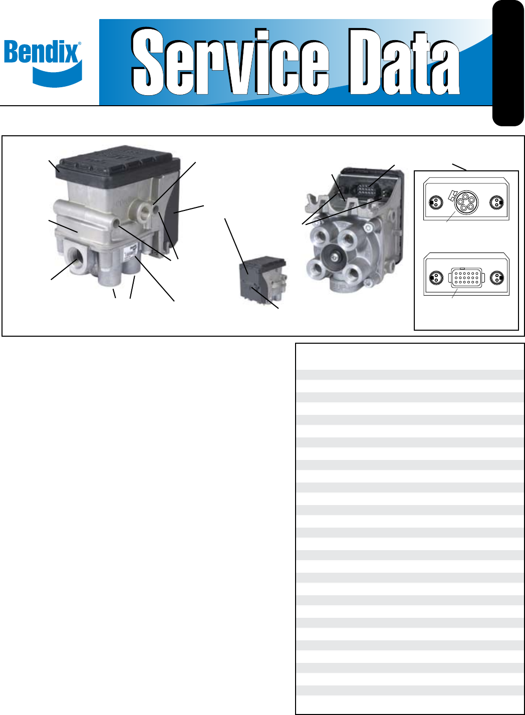
Bendix® TABS-6 Trailer ABS Module
FIGURE 1 - TABS-6 STAndARd And PREmIUm mOdULES
INTRODUCTION
The Bendix® TABS-6 module is an integrated trailer ABS
controller and modulator for air-braked heavy-duty trailers,
semi-trailers and dollies. The module acts as a relay valve
during normal braking, but during ABS events, it will intervene
to help improve stability. All modules include an Electronic
Control Unit (ECU) and Modulator Relay Valve (MRV) which are
integrated into a single self-contained 2S/1M (two-sensor, one
modulator) trailer ABS unit. The Premium TABS-6 module is
auto-congurable to control more sensors and modulators (up to
4S/3M) from its default 2S/1M.
Bendix® TABS-6 modules also feature:
• Internal electrical connections to the primary MRV,
eliminating the need for external pigtail harnesses.
• Optional mounting to the service reservoir or to the chassis,
without additional brackets.
• Blink code diagnostics and support for advanced diagnostic
tools.
• Support for Power Line Carrier (PLC) communication to the
towing vehicle.
• A pressure equalizing valve in the sealed ECU housing to
give improved protection from water, etc.
• A locking dust cover to provide additional electrical connector
and cable protection.
• A serviceable nylon lter to help prevent foreign material
from entering the control port.
TABLE OF CONTENTS PAGE
General System Information
Introduction................................1
Safe Maintenance Practices. . . . . . . . . . . . . . . . . . .2
Components...............................2
Mounting Congurations......................2
PLC Communications........................2
Wiring Harness (Pigtail) . . . . . . . . . . . . . . . . . . . . . .3
Power and Ground . . . . . . . . . . . . . . . . . . . . . . . . . .4
ABS Indicator Lamp .........................4
Wheel Speed Sensors . . . . . . . . . . . . . . . . . . . . . . .5
BR9235™ ABS Modulator Valve . . . . . . . . . . . . . . . .5
J1708/J1587 Diagnostic Link . . . . . . . . . . . . . . . . . .6
Auxiliary I/O ...............................6
ABS Flex™ Program .........................6
Customer Scratch Pad . . . . . . . . . . . . . . . . . . . . . . .6
Power-up Sequence.........................6
ABS Operation .............................7
Auto-Conguration ..........................8
Odometer Function..........................8
Non-standard Tire Size . . . . . . . . . . . . . . . . . . . . . . .8
Diagnostic Trouble Code Detection . . . . . . . . . . . . . 8
Blink Code Diagnostics. . . . . . . . . . . . . . . . . . . . . . .9
Bendix ABS Diagnostic Tools . . . . . . . . . . . . . . . . .13
Contacting Bendix..........................14
Servicing the Module . . . . . . . . . . . . . . . . . . . . . . .14
Removing the Module. . . . . . . . . . . . . . . . . . . . . . .14
Service Replacement using the Module . . . . . . . . . 15
Reinstallation .............................15
Leakage And Operational Tests . . . . . . . . . . . . . . .15
ABS Wiring...............................16
Troubleshooting . . . . . . . . . . . . . . . . . . . . . . . . 17-27
3/4" NPT
Supply Port
Through-holes
for Frame
(Chassis)
Mounting
Wheel Speed
Sensor
Connectors
ECU Pin-out Label
(See Page 31)
ECU Cover
(Sealed)
ECU Connector
Cover
(Removable)
Four (4) 3/8" NPT
Delivery Ports
(To Brake Chambers)
3/8" NPT Control
Port with
Integral Filter
The ECU Connector
Varies for Standard and
Premium - See Chart
Integrated
Modulator
Relay Valve
Part Number
Label
(See Page 31)
To Remove Cover
Slide Lock Tab
The Premium TABS‑6
Module uses an
18‑Pin Connector
The Standard TABS‑6
Module uses a
5‑Pin Connector
SD-13-4767

2
COMPONENTS
Installations of the TABS-6 Module typically utilize the
following components:
• Bendix® WS-24™ wheel speed sensors (2 or 4,
depending on conguration). Each sensor is installed
with a Bendix Sensor Clamping Sleeve. See page 5.
• Bendix® BR9235™ Pressure Modulator Valves (0, 1, or
2 depending on conguration). See page 5.
• Trailer-mounted ABS indicator lamp. See page 4.
• Pigtail wiring harness(es) as needed. See page 3.
MOUNTING CONFIGURATIONS
Tank (Nipple) Mount
The TABS-6 modules can be tank-mounted using a
schedule 80 (heavy gauge steel) 3/4" NPT nipple directly
between the trailer supply tank and the module's supply
port. A tank with a reinforced port must be used.
Frame (Chassis) Mount
The TABS-6 module provides through-holes for frame
mounting directly to the trailer frame rail or cross-member.
It is recommended to use two Grade 5 3/8-16 bolts, typical
length 5", torqued to 180-220 in-lbs.
POWER LINE CARRIER (PLC)
COMMUNICATIONS
Since March 1, 2001, all new towed vehicles transmit a
signal over the power line to an in-cab trailer ABS Indicator
Lamp. The signal, using a heavy vehicle industry standard
known as “PLC4Trucks,” is typically broadcast by the
trailer ABS ECU over the blue wire (power line) of the J560
connector. See Figures 2 and 3.
TABS-6 modules support PLC communications in accord-
ance with SAE J2497.
Identifying and Measuring the PLC Signal
A TABS-6 module will continuously broadcast PLC
messages that indicate trailer ABS status. At power-up or
during a trailer ABS fault condition, the TABS-6 module will
signal the tractor ABS unit to illuminate the dash-mounted
trailer ABS indicator lamp.
Diagnostic tools are available that detect the presence
of a PLC signal and perform further system diagnostics
directly on the power line. For more information on these
diagnostic tools, contact Bendix or refer to your local
authorized Bendix dealer or distributor.
An oscilloscope can also be used to verify the presence
and strength of a PLC signal on the power line. The PLC
signal is an amplitude and frequency modulated signal.
Depending on the load on the power line, the amplitude of
the PLC signal can range from 5.0 mV p-p to 7.0 V p-p.
SAFE MAINTENANCE PRACTICES
WARnInG! PLEASE REAd And FOLLOW
THESE InSTRUCTIOnS TO AVOId
PERSOnAL InJURY OR dEATH:
When working on or around a vehicle, the following
general precautions should be observed at all times:
1. Park the vehicle on a level surface, apply the parking
brakes, and always block the wheels. Always wear
safety glasses.
2. Stop the engine and remove ignition key when
working under or around the vehicle. When working
in the engine compartment, the engine should be
shut off and the ignition key should be removed.
Where circumstances require that the engine be in
operation, EXTREME CAUTION should be used to
prevent personal injury resulting from contact with
moving, rotating, leaking, heated or electrically
charged components.
3. Do not attempt to install, remove, disassemble
or assemble a component until you have read
and thoroughly understand the recommended
procedures. Use only the proper tools and observe
all precautions pertaining to use of those tools.
4. If the work is being performed on the vehicle’s
air brake system, or any auxiliary pressurized air
systems, make certain to drain the air pressure from
all reservoirs before beginning ANY work on the
vehicle. If the vehicle is equipped with an AD-IS® air
dryer system or a dryer reservoir module, be sure
to drain the purge reservoir.
5. Following the vehicle manufacturer’s recommended
procedures, deactivate the electrical system in a
manner that safely removes all electrical power from
the vehicle.
6. Never exceed manufacturer’s recommended
pressures.
7. Never connect or disconnect a hose or line
containing pressure; it may whip. Never remove a
component or plug unless you are certain all system
pressure has been depleted.
8. Use only genuine Bendix® replacement parts,
components and kits. Replacement hardware,
tubing, hose, ttings, etc. must be of equivalent
size, type and strength as original equipment and
be designed specically for such applications and
systems.
9. Components with stripped threads or damaged
parts should be replaced rather than repaired. Do
not attempt repairs requiring machining or welding
unless specifically stated and approved by the
vehicle and component manufacturer.
10. Prior to returning the vehicle to service, make certain
all components and systems are restored to their
proper operating condition.
11. For vehicles with Antilock Traction Control (ATC),
the ATC function must be disabled (ATC indicator
lamp should be ON) prior to performing any vehicle
maintenance where one or more wheels on a drive
axle are lifted off the ground and moving.
3
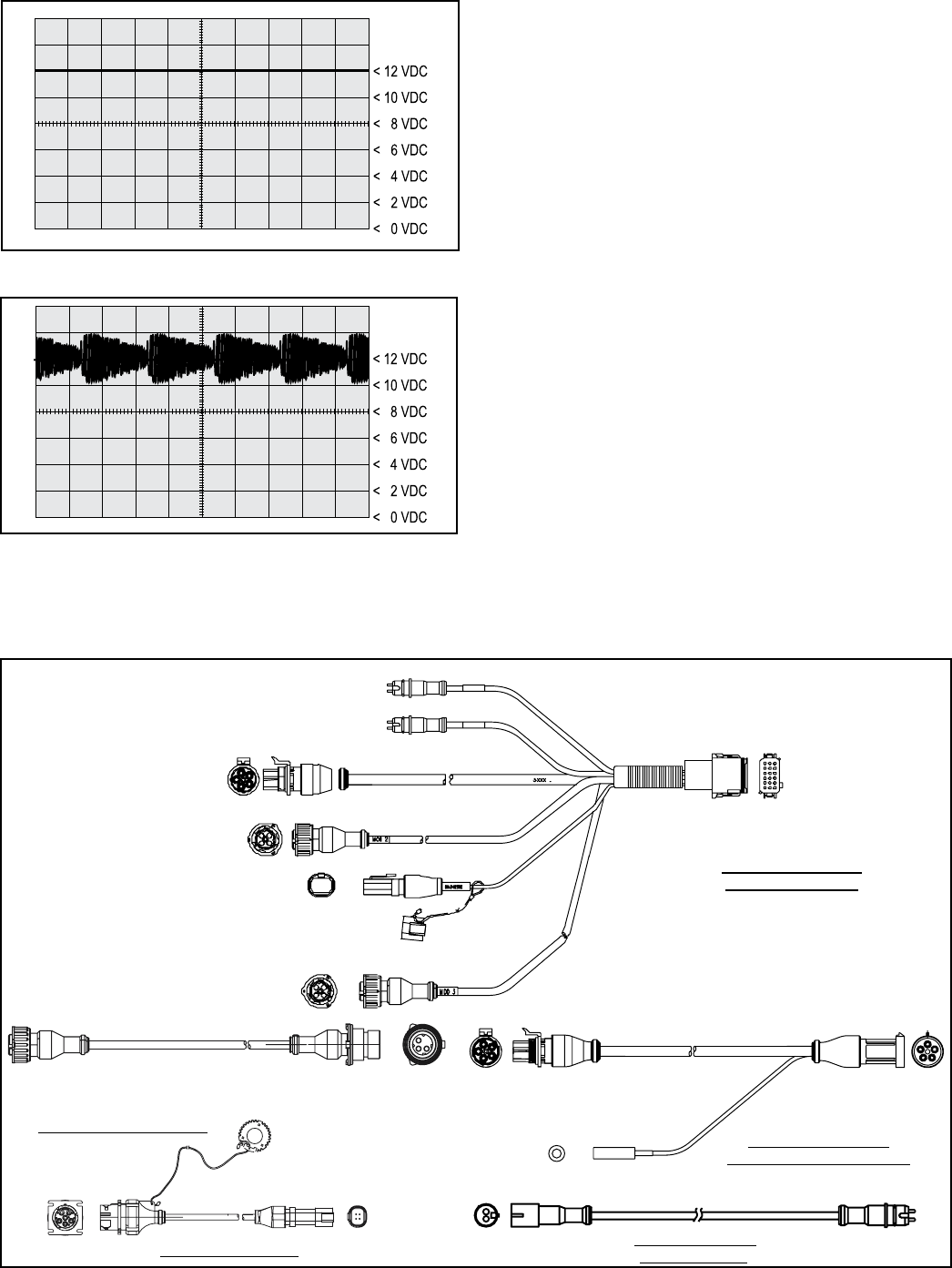
FIGURE 2 - POWER LInE WITHOUT PLC SIGnAL
FIGURE 3 - POWER LInE WITH PLC SIGnAL
Suggested oscilloscope settings are (AC coupling, 1 volt/
div, 100 µsec/div). The signal should be measured on pin
7 of the J560 connector at the nose of the trailer.
PIGTAIL WIRING HARNESSES
Several pigtail wire harnesses are available to connect
the TABS-6 module with ABS and other trailer system
components. Pigtail harness are weather sealed at the
connector interface and are clearly labeled for proper
installation. Because of the over-molded design of the
TABS-6 module wiring harnesses, Bendix recommends that
the complete harness be replaced if damage or corrosion
occurs.
The following connector options may be present:
Modulator 2 (MOD2), Modulator 3 (MOD3), auxiliary,
diagnostic, and additional axle wheel speed sensors.
Note: All TABS-6 modules include the two primary wheel
speed sensor connections and therefore these are separate
from the pigtail harness.
ECU Connectors
Standard TABS-6 module ECU connectors use a TTMA
97-99 5-pin Packard Weather Pack connector for brake
light power, constant power, ground, the trailer-mounted
ABS indicator lamp and a single auxiliary input/output
(I/O).
Premium TABS-6 module ECU connectors use an 18-pin
Deutsch DT series connector for the same function as
above, plus additional modulators, wheel speed sensors
and auxiliary I/O’s.
FIGURE 4 - ExAmPLES OF PIGTAIL WIRE HARnESSES AVAILABLE
Premium Pigtail Harness
(4S/2M with diagnostic)
18-Pin ECU Connector
2-Pin Additional
Wheel Speed
Sensor
Connectors
(SAL & SAR)
4-Pin Diagnostic
5-Pin Power and
Indicator
Lamp (POWER/
WL)
3-Pin Modulator 3
(MOD3) (Optional)
3-Pin Modulator 2
(MOD2)
Auxiliary
(Optional)
5XXX...
To ECU or Pigtail
To TABS-6 Module
Pigtail
To Diagnostic
Tool
5XXX... E
B
A
D C
5XXX....
5-Pin Power and
Indicator Lamp
(POWER/WL)
5-Pin ECU
Connector
To TABS-6 Module
Pigtail
To BR9235™ ABS Modulator
Relay Valve
Optional
Diagnostic
To WS-24™ Wheel
Speed Sensor
Standard Pigtail Harness
(2S/1M) with optional diagnostic
Modulator Extension Harness
Wheel Speed Sensor
Extension Harness
Diagnostic Tool Harness
4
ABS INDICATOR LAMP
Trailer-mounted Lamp
The TABS-6 module controls an ABS indicator lamp to show
the trailer ABS status. With power supplied by the towing
vehicle, the module illuminates the ABS indicator lamp by
providing a 12.0 VDC signal. (The other side of the lamp
is grounded.) The ABS indicator lamp output uses Pin D
of the 5-pin Standard module connector, and Pin 5 of the
18-pin Premium module connector.
Dash-mounted Lamp (PLC Controlled)
TABS-6 modules use SAE J2497 standards to support
Power Line Carrier (PLC) communication. The TABS-6
module transmits a signal over the power line to the towing
vehicle. This information is used by towing vehicle’s
ABS controller to know when to illuminate the trailer ABS
indicator lamp mounted on the dash.
The status of the trailer ABS is transmitted over the ignition
power wire (blue wire of the J560 connector), Pin B of the
5-pin Standard module connector, or Pin 6 of the 18-pin
Premium module connector.
Power/ABS Indicator Lamp Connector
The TABS-6 module pigtail uses a TTMA RP 97-99 5-pin
Packard Weather Pack connector for brake light power,
constant power, ground and the trailer-mounted ABS
indicator lamp.
The Power/ABS indicator lamp lead of the pigtail harness
is available in several lengths to satisfy most installation
requirements (e.g. slider axles).
Wheel Speed Sensor Connectors
Two 2-pin connectors are provided for additional wheel
speed sensors for 4S ABS applications. These 2-pin
connectors are labeled Additional Sensor Left (SAL), and
Additional Sensor Right (SAR). Extension cables are
available in various lengths from Bendix.
ABS Modulator Connectors
On Premium TABS-6 module pigtail harnesses, one or two
modulator connectors are provided for trailers using two
or three modulators. These 3-pin connectors are labeled
MOD2 and MOD3. (Note: MOD1 designates the internal
modulator of the TABS-6 module). Remote modulator
harnesses are available in many lengths to satisfy most
installation requirements.
Diagnostic Connector
Premium TABS-6 module pigtail harnesses provide a 4-
pin diagnostic connection for a diagnostic tool to monitor
ECU ignition power, ground and data information. Remote
diagnostic cables are available from Bendix to provide a
standard J1708/J1587 diagnostic port at the side of the
trailer.
Auxiliary I/O Connector
Standard TABS-6 module pigtails provide an option for
a single auxiliary I/O. An optional auxiliary connector
provides a connection to the TABS-6 module auxiliary I/O
ECU pins. Premium ECU pigtails provides an option for
up to six auxiliary I/O’s.
POWER AND GROUND
Trailer electrical power is supplied to the TABS-6 module
from the ignition and brake light circuits. See Charts 1 and
2 for output values and pin locations.
FIGURE 5 - TRAILER-mOUnTEd ABS IndICATOR LAmP
7-Pin 5-Pin 5-Pin 18-Pin
Circuit Trailer ABS ECU ECU
Conn. Conn. Conn. Conn.
Ignition Power
PLC (Blue Wire)
Brake Light
Power 4 A A 12
(Red Wire)
Ground
(White Wire)
Indicator Lamp
(White/green N/A D D 5
Wire)
CHART 2 – POWER And GROUnd
7 B B 6
1 E E 18
CHART 1 – VALUES FOR OUTPUTS
Function Mode Value
Operating Range 8.0 to 16.0 VDC
ECU Active 135 mA @ 12 VDC
ABS Active 3.7 A @ 12 VDC
(1 Modulator)
ABS Active 5.2 A @ 12 VDC
(2 Modulators)
5
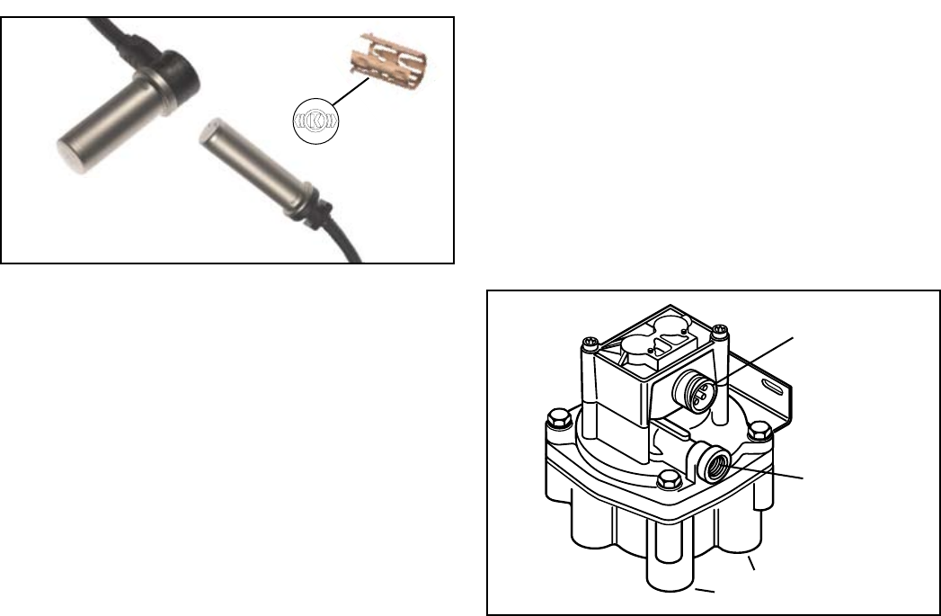
FIGURE 6 - BEndIx® WS-24™ WHEEL SPEEd SEnSORS
90° Speed
Sensors
Straight Speed
Sensors
Sensor
Clamping
Sleeve
1. For increased corrosion protection we recommend
that a high-temperature rated silicon- or lithium-based
grease be applied to the interior of the mounting block,
the sensor, and to a new clamping sleeve.
2. Install the new clamping sleeve fully into the block,
with the retaining tabs toward the inside of the vehicle.
Please note that WS-24™ wheel speed sensors must
use the correct clamping sleeve to avoid problems
associated with reduced retention force, such as sensor
movement and resulting ABS trouble codes.
3. Gently push (DO NOT STRIKE) the sensor into the
mounting block hole until it bottoms out on the face of
the tone ring. Secure the cable lead wire to the knuckle/
axle housing 3-6 inches from the sensor.
4. Apply a moderate amount of dielectric non-conductive
grease to both the sensor connector and harness
connector.
5. Engage the connectors, and push together until the
lock tab snaps into place.
NOTE: It is important for the wheel bearings to be
adjusted per the manufacturer's recommendations.
The friction t allows the WS-24™ sensor to slide back and
forth under force but to retain its position when the force
is removed. When the WS-24™ sensor is inserted all the
way into the mounting block and the wheel is installed on
the axle, the hub exciter contacts the sensor, which pushes
the sensor back. Also, normal bearing play will “bump” the
sensor away from the exciter. The combination of these
two actions will establish a running clearance or air gap
between the sensor and exciter.
Excessive wheel end play can result in diagnostic trouble
codes in cases where the sensor is pushed too far away
from the tone ring.
BENDIX® BR9235™ ABS MODULATOR
RELAY VALVES
Bendix® BR9235™ modulator relay valves (MRV) are
required when additional modulator relay valves are
needed for multichannel brake systems (e.g. 2S/2M, 4S/3M
ABS congurations).
The MRV is an electro-pneumatic control valve and is the
last valve that air passes through on the way to the brake
chambers. The normally-open hold solenoid and normally-
closed exhaust solenoid are activated to precisely modify
the brake pressure on command. During normal braking,
the BR9235™ MRV functions as a standard relay valve. As
brakes are applied or released by the driver, the control
signal from the tractor foot valve causes the BR9235™
MRV to apply proportional pressure to the trailer brake
chambers.
The BR9235™ MRV is available in both tank and bracket
mounting styles.
BENDIX® WS-24™ WHEEL SPEED SENSORS
Wheel speed data is provided to the TABS-6 module from
the WS-24™ wheel speed sensors (see Figure 6). Vehicles
have an exciter ring (or “tone ring”) as part of the wheel
assembly, and as the wheel turns, the teeth of the exciter
ring pass the wheel speed sensor, generating an AC signal.
The TABS-6 module receives the AC signal, which varies in
voltage and frequency as the wheel speed changes. (The
default setting expects a 100-tooth tone ring to be used.)
Vehicle axle and ABS control congurations determine if
two or four wheel speed sensors are required. See page
17 for electrical system schematics showing wheel speed
sensor connector pin locations.
A proper sensor installation is critical to correct ABS
operation.
Typically, the WS-24™ sensor is installed in mounting blocks
that are welded to the axle housing. WS-24™ wheel speed
sensors are protected by a stainless steel sheath. They
are designed to be used with beryllium copper clamping
sleeves (sometimes referred to as a “retainer bushing”,
“friction sleeve” or “clip”) (See Figure 6). The clamping
sleeve provides a friction t between the mounting block
bore and the WS-24™ sensor.
Logo Stamped
into Sleeve
FIGURE 7 - BEndIx® BR9235™ mOdULATOR RELAY
VALVE
3-Pin Modulator
Solenoid
Connector
3/8" NPT Supply
Port with Integral
Filter
Four 3/8" NPT Delivery Ports
(to Brake Chambers)

6
Tank (Nipple) Mounted
The BR9235™ MRV can be tank-mounted using a schedule
80 (heavy gauge steel) 3/4" NPT nipple directly between
the trailer supply tank and the supply port. A tank with a
reinforced port must be used.
Bracket (Chassis) Mounted
The BR9235™ MRV provides an option with a bracket
for frame mounting directly to the trailer frame rail or
crossmember. It is recommended to use two Grade 5,
3/8-16 bolts, torqued to 180 – 220 in-lbs.
J1708/J1587 DIAGNOSTIC LINK
The Premium TABS-6 module provides a J1708/J1587
diagnostic link with data and power to communicate with
the vehicle and various diagnostic tools. Diagnostics,
testing, conguration, data transfer and other functions can
be performed using this link. Diagnostic tools such as the
MPSI Pro-Link™ device and Bendix® ACOM™ Diagnostic
Software (version 4.0 and higher) support the TABS-6
Module.
Ignition power must be provided to the TABS-6 module for
the diagnostic link to be active.
AUXILIARY I/O
The Standard module provides for one auxiliary I/O
function.
The Premium module provides for up to ve auxiliary
functions and one additional ground. See Chart 3, below.
Bendix® ACOM™ Diagnostic Software (version 4.0 and
higher) supports the conguration of the TABS-6 module
auxiliary I/O’s.
ABS FLEX™ PROGRAM
The ABS Flex™ program uses Auxiliary Design Language
(ADL) to allow customized auxiliary functions to be carried
out by the TABS-6 module. Programs developed in the ABS
Flex™ program may be downloaded at the production line or
in the eld to control non-braking functions of the trailer.
For example, ABS Flex™ program can potentially
communicate the status of: tire ination and/or temperature;
reefer temperature; load presence; slider pin position;
lift axle position; proximity/reverse alarm; and vehicle
weight.
ABS Flex™ programs monitor the auxiliary I/Os and/or the
SAE J1587 diagnostics and SAE J2497 PLC data links.
Contact your Bendix Account Manager to discuss an ABS
Flex™ program for your vehicle(s).
CUSTOMER SCRATCH PAD
The TABS-6 module has a Customer Scratch Pad feature
which allows the customer, or end-user, to store up to 756
bytes of information. This information can then be read
using the Bendix® ACOM™ Diagnostic Software (version
4.0 and higher).
If additional scratch pad space is needed, this storage
space can be expanded to 1K (1,008 bytes total of data).
Contact Bendix for further details.
POWER-UP SEQUENCE
At power-up, the TABS-6 module performs a series of self-
checks that can assist a technician to determine the ABS
system status and conguration.
Name ECU ECU Pin Auxiliary Functions Default Function
AUX Standard C None
AUX1 Premium 16 • High-Side Driver… or Digital Input Modulator 3 (MOD3)
Hold Solenoid
AUX2 Premium 10 • High-Side Driver… or Digital Input Modulator 3 (MOD3)
Release Solenoid
AUX3 Premium 15 • High-Side Driver… or Digital Input Modulator 2 (MOD2)
Hold Solenoid
AUX4 Premium 9 • High-Side Driver… or Digital Input Modulator 2 (MOD2)
Release Solenoid
AUX5 Premium 4 • Low-Side Driver… or Analog Input Modulator 3 (MOD3)
Common
AUX6 Premium 3 • High-Side Driver… or Digital Input J1587 Diagnostic Power
CHART 3 – AUxILIARY I/OS And dEFAULT FUnCTIOnS
• High-Side Driver… or Digital Input…
or • Analog Input
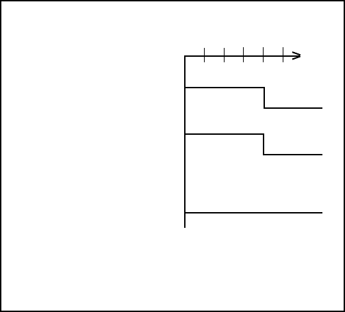
7
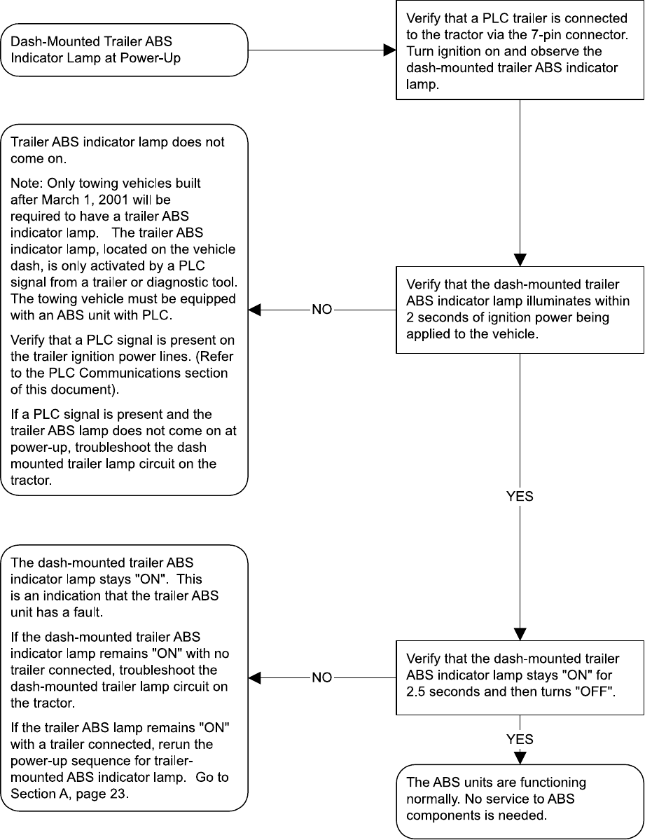
Trailer ABS indicator lamp
At power-up without detected faults, the trailer ABS
indicator lamp will turn on for 2.5 seconds as a bulb check
and then turn off. See Figure 8.
If a PLC-ready towing vehicle and trailer are powered at
the same time, the TABS-6 module will also trigger a bulb
check on the dash-mounted trailer ABS indicator lamp.
Modulator Chuff Test at Power-Up
At power-up, the TABS-6 module activates a modulator
chuff test. This electrical and pneumatic ABS modulator
test can help the technician identify problems with
modulator installations and/or wiring.
With brake pressure applied, a properly installed modulator
will cause ve rapid audible chuffs of air pressure. If
additional modulators are installed, the TABS-6 module
activates 5 chuffs at the internal modulator (MOD1) then
for each additional modulator in sequence (e.g. MOD1,
then MOD2, and then MOD3). The chuff sequence is
then repeated.
If the modulator is wired incorrectly, the modulator will only
produce one chuff, or no chuff at all. If an issue is detected
during the modulator chuff test, compare the modulator
wiring and plumbing to the TABS-6 module’s electrical
system schematic (see page 17) and make repairs.
ABS OPERATION
The TABS-6 module uses wheel speed sensors, modulator
relay valves and an ECU to control trailer wheels by axle
or by side. By monitoring individual wheel turning motion
during braking, and adjusting or pulsing the brake pressure
at each wheel, the TABS-6 module is able to optimize slip
between the tires and the road surface. When excessive
wheel slip, or wheel lock-up, is detected, the ECU will
activate the Pressure Modulator Valves to modulate
braking pressure at the wheel ends. The ECU is able to
pump the brakes on individual wheels (or pairs of wheels),
independently, and with greater speed and accuracy than
a driver.
Axle Control
TABS-6 module axle control uses a single modulator relay
valve to control wheels on both sides of a given axle or
axles. In the case of an ABS event on road surfaces with
poor traction (worn, slippery, or loose gravel roads) or areas
of poor traction, (e.g. asphalt road surfaces with patches of
ice), axle control will maintain the wheel that is not slipping
at just under the speed that will lock the wheel. Temporary
periods of wheel lock are permitted on the other wheel that
is experiencing slippage.
Axle control should not be used on 5th wheel dollies or
steerable axles. When braking on even surfaces, an
axle-control system will perform similar to a side control,
two-modulator system. Axle control is available in 2S/1M,
2S/2M and 4S/2M installations, and for Modulator 3
(MOD3) in a 4S/3M installation.
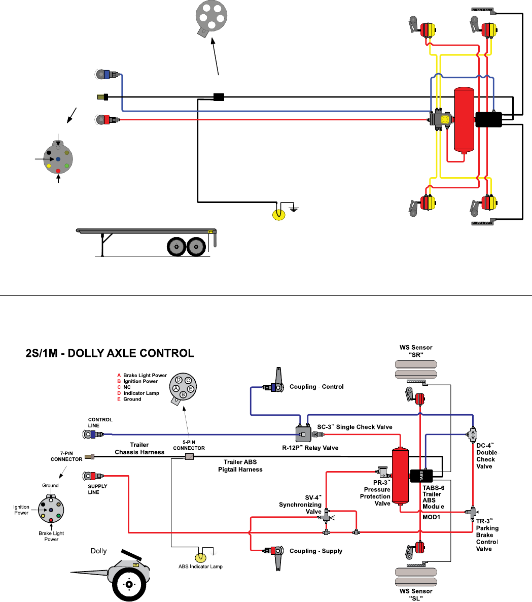
Dolly-Axle Control (Select Low)
TABS-6 module dolly-axle control uses a single ABS
modulator valve to control wheels from both sides of a
given axle or axles. In the case of an unbalanced braking
surface, (e.g. asphalt road surfaces with patches of ice),
dolly axle control will control the low coefcient (slipping)
wheel just under the lock limit. Vehicle stability is assisted
by not allowing the high coefcient wheel (where traction
is still being maintained) to sustain wheel lock.
When braking on even surfaces, a dolly axle control system
will perform similar to side control or axle control system.
Dolly axle control is only available in 2S/1M installations.
Side Control
The TABS-6 module uses a single modulator relay valve
to control one or more wheels on a given vehicle side. In
the case of an unbalanced braking surface, the side control
will individually control wheels on each side just under the
point where they would lock up.
Side control is available in 2S/2M and 4S/2M installations,
and for the internal modulator (MOD1) and Modulator 2
(MOD2) in the 4S/3M installation.
Normal Braking
During normal braking, the TABS-6 module functions as a
standard relay valve. If the ECU does not detect excessive
wheel slip, it will not activate ABS control, and the vehicle
stops with normal braking.
FIGURE 8 - TRAILER ABS LAmP START UP SEqUEnCE
*Some vehicle manufacturers may illuminate the trailer ABS
indicator lamp at power-up regardless of whether a PLC
signal is detected from the trailer or not. Consult the vehicle
manufacturer’s documentation for more details.
Dash-mounted Trailer
ABS Indicator Light (PLC
Detected)*
Dash-mounted Trailer
ABS Indicator Light
(PLC Not Detected)
Trailer-mounted ABS
Indicator Light
ABS System
Status Indicators
Power
Application
ON
OFF
0.5
ON
OFF
2.0 2.5 3.0 (sec.)1.5
ON
OFF

8
ODOMETER FUNCTION
Odometer
The TABS-6 module includes an odometer function to
provide a means of storing the accumulated mileage of the
vehicle. The mileage is computed by utilizing information
calculated from the vehicle wheel speeds.
This feature is accurate to within 0.62 miles per power-up
and will typically store mileage up to 1,000,000 miles. The
mileage can be displayed using PC diagnostics or through
blink codes.
Whenever the module is towed using a pre-1997 tractor,
the electronic odometer does not function, and the mileage
can be considered out-of-calibration.
Trip Counter
The module provides a counter to record the trip mileage.
The feature is accessed through PC or handheld diagnostic
tools.
Service Interval
The TABS-6 module provides a feature that can be used
to indicate a service interval for the trailer. The service
interval can be accessed via PC or hand-held diagnostic
tools. If congured, the TABS-6 module can ash the
indicator lamp when the vehicle is at standstill to indicate
when the service interval has been exceeded.
NON-STANDARD TIRE SIZE
The module allows for tire rolling radius and tone ring
tooth count parameters to be set for each axle using a
diagnostic tool. These adjustments may be necessary for
the module to accurately calculate the vehicle velocity and
odometer mileage. Wheels of the same axle must be set
to the same rolling radius and tone ring tooth count. In
most cases, these parameters are set by the trailer OEM
and do not need to be adjusted. In the case of a service
replacement unit, always check that these parameters are
set to match the vehicle.
The tire-rolling radius is defaulted to 500 revs/mile and can
be adjusted from 300 to 700 revolutions per mile. Refer to
the manufacturer’s tire specication for correct values.
Tone ring tooth count is defaulted to 100 teeth and can be
set to 60 to 140 teeth.
DIAGNOSTIC TROUBLE CODE DETECTION
The TABS-6 module contains self-testing diagnostic
circuitry that monitors the ABS components and wiring.
When the module senses an erroneous system condition,
it activates the external trailer-mounted ABS indicator lamp,
disables all or part of the affected ABS functions, and it
stores the fault code in memory, even when the power is
removed. The module also uses PLC communications to
send the system status to the towing vehicle.
For some trouble codes, the TABS-6 module will
automatically reset (“self-heal”) the active diagnostic
trouble code when the error is corrected (e.g. when a
wheel speed sensor is re-aligned). However, repeated
occurrences of a given trouble code can cause the code to
“latch” - that is, be retained as active, even if the condition
is only intermittent. Once the code is latched, a manual
reset will be necessary. Technicians can use these latched
codes to assist them in troubleshooting intermittent errors.
After the problem is repaired, trouble codes can be reset
using blink code diagnostics or with a diagnostic tool.
When a trouble code self-heals or is manually reset, the
code remains stored in the ECU memory. This trouble
code history can be retrieved using blink code diagnostics
or with a diagnostic tool.
AUTO-CONFIGURATION
The Standard TABS-6 module is available only in the 2S/1M
ABS conguration and does not use auto-conguration.
For the Premium TABS-6 module, the default ABS
conguration is 2S/1M. At power-up, if a Premium ECU
detects additional sensors and modulators it will perform an
auto-conguration. Auto-conguration only adjusts upward
(e.g. 2S/2M Side to a 4S/2M Side conguration).
Additional detected components that do not conform to a
legitimate conguration will generate the appropriate faults.
If the vehicle begins moving before the new conguration
has been accepted, the reconguration will not take place
at this time.
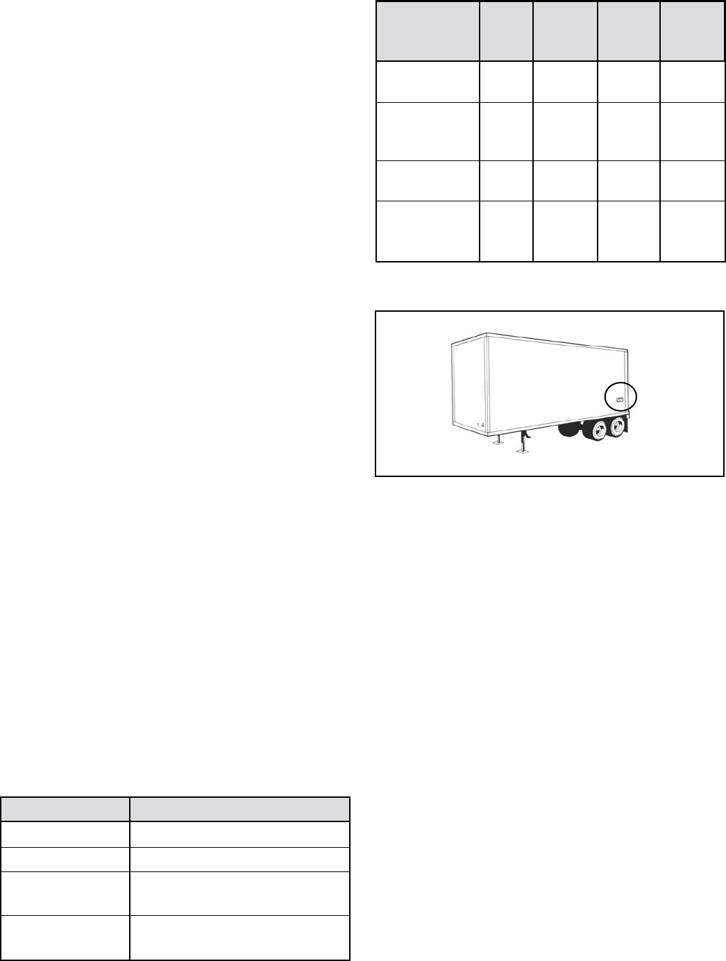
CHART 4 – PREmIUm TABS-6 mOdULE AUTO-
COnFIGURATIOn mATRIx
Additional Components
Sensors Modulators
- - 2S/1M (Dolly-Axle)
- 1 to 2S/2M (Side)
2 1 to 4S/2M (Side)
2 2 to 4S/3M (Side/Axle)
- - 2S/1M (Axle)
- 1 to 2S/2M (Axle)
2 1 to 4S/2M (Axle)
Auto-Conguration
Default
2S/1M
Dolly Axle
2S/1M
Axle

9
PARTIAL ABS SHUTDOWN
Depending on the trouble code detected, the ABS ECU
partly or completely disables the ABS functionality.
The trailer ABS system, for vehicles that only have one
modulator, are disabled by any single fault. In the case of
vehicles with two or three modulators, depending on the
trouble code, the trailer ABS system may still provide some
level of ABS function on axles/wheels that are not affected
by the fault, but the ABS indicator lamp will remain on. In
cases where the ABS is completely disabled, the vehicle
reverts to normal braking (without ABS interventions).
Always repair ABS shutdowns at the earliest opportunity.
ECU Diagnostic Trouble Codes
All ABS functions are completely disabled. The system
reverts to normal braking.
Voltage Diagnostic Trouble Code
While voltage is out of range, the ABS functionality is
disabled and the system reverts to normal braking. When
the correct voltage level is restored, full ABS is typically
available again. The operating voltage range is 8.0 to
16.0 VDC.
BLINK CODE DIAGNOSTICS
The TABS-6 module provides diagnostic and conguration
functions through blink code diagnostics. This means that
the technician, even without diagnostic tools, can read a
series of ABS indicator lamp blinks to diagnose the trouble
codes being generated.
The blink code diagnostics mode is entered by providing
constant power to the ignition circuit and toggling the
brake light power input three times. With a parked towing
vehicle attached, this is done by applying ignition power
and after the power up sequence is complete, depressing
and releasing the brake pedal three or more times, see
below for chart.
Depending on the blink code mode activated, the TABS-6
module will blink the trailer-mounted ABS indicator
lamp to display: active fault codes; fault code history;
ABS congurations; and odometer mileage. Blink code
diagnostics can also be used to reset active fault codes.
Wait until after the modulator chuff test before activating
the brake light power. Following a single display of all
available messages, the ABS indicator lamp will remain on
for ve seconds and then return to normal operating mode.
Blink code diagnostics can only be activated following a
power-up, where wheel speeds have not been detected. If
the vehicle moves during blink code diagnostics mode, the
module will cancel the blink code diagnostics and return to
normal operating mode.
Blink code diagnostics must be activated within the rst 15
seconds of ignition power being applied.
If brake light power is continuously applied for greater than
ve seconds, blink code diagnostics will be disabled until
the next time the ignition power is cycled.
Display Active Diagnostic Trouble Codes
To display active codes, apply ignition power and depress
/ release the brake pedal 3 times within 15 seconds.
Following activation, there will be a 5-second delay followed
by a blink code display of all active fault codes. (See pages
10-12 for more information.)
Display Diagnostic Trouble Code History
To display trouble code history, apply ignition power
and depress / release the brake pedal 4 times within 15
seconds. Following activation, there will be a 5-second
delay followed by a blink code display of all history fault
codes. (See pages 10-12 for more information.)
Reset Active Diagnostic Trouble Codes
To reset active codes, apply ignition power and depress
/ release the brake pedal 5 times within 15 seconds.
Following activation, there will be a 5-second delay followed
by a blink code message of:
1-1, (System Fully Operational - No Codes Detected) or a
blink code display of all remaining active fault codes.
The ABS indicator lamp will stay on if active DTCs are still
present.
Resetting active fault codes with blink code diagnostics
does not clear information from trouble code history. Both
blink code diagnostics or diagnostic tools can retrieve
trouble code history, but only diagnostic tools can erase
this information.
CHART 5 – BLInk COdE InFORmATIOn
With Ignition Power Blink Code
Applied, Cycle Brake Action
Light Power
3 times Display Active DTCs
4 times Display Inactive DTCs
5 times Clear Active DTCs
6 times Display Conguration
7 times Display Odometer Mileage
8 times Reset Conguration
10
Display Conguration
To check the ABS conguration, apply ignition power
and depress / release the brake pedal 6 times within 15
seconds. Following activation, there will be a 5-second
delay followed by a blink code display of the module's
current ABS conguration.
CHART 6 – ABS COnFIGURATIOnS
Display Odometer Mileage
To display the trailer odometer mileage, apply ignition
power and depress / release the brake pedal 7 times within
15 seconds. Following activation, there will be a 5-second
delay followed by a blink code display of the odometer
information (x1000).
Example: 152,431 miles will be displayed as: 152 (x1000)
or 1 blink (pause), 5 blinks (pause), 2 blinks.
Zeros will be displayed by the ABS indicator lamp strobing
twice.
Odometer mileage cannot be altered with blink code
diagnostics. Complete odometer information can be
retrieved using a diagnostic tool.
Resetting ABS Conguration
To reset the ABS conguration to the default conguration,
apply ignition power and depress / release the brake
pedal 8 times within 15 seconds. Following activation,
the TABS-6 ABS conguration will reset to the default ABS
conguration (2S/1M).
1st Digit Sensors
2 2 Sensors
4 4 Sensors
2nd Digit Modulators
1 1 Modulator
2 2 Modulators
3 3 Modulators
3rd Digit ABS Control Mode
1 Axle
2 Side
3 Dolly-Axle
4 MOD1 Axle - MOD2 Dolly-Axle
5 MOD1 Axle - MOD2 Lift Axle
6 Side (MOD1, MOD2) - MOD3 Dolly-Axle
Diagnostic Trouble Codes (DTCs)
1st 2nd Fault Description Repair Information J1587 J1587
Digit Digit (SID) (FMI)
1 1 No faults • ABS system fully operational – no faults detected 1 0
WHEEL SPEED SENSORS (WSS)
2 1 SL Sensor signal valid - large air gap 1 0
3 1 SR Sensor signal valid - large air gap 2 0
4 1 SAL Sensor signal valid - large air gap 3 0
5 1 SAR Sensor signal valid - large air gap 4 0
2 2 SL Sensor signal valid - loss of signal 1 1
3 2 SR Sensor signal valid - loss of signal Dynamic Wheel Speed Sensor Fault. 2 1
4 2 SAL Sensor signal valid - loss of signal Go to Section G, on Page 29. 3 1
5 2 SAR Sensor signal valid - loss of signal 4 1
2 3 SL Sensor signal valid – noisy 1 2
3 3 SR Sensor signal valid – noisy 2 2
4 3 SAL Sensor signal valid – noisy 3 2
5 3 SAR Sensor signal valid – noisy 4 2
2 4 SL Sensor shorted or open 1 4 or 5
3 4 SR Sensor shorted or open Static Wheel Speed Sensor Fault. 2 4 or 5
4 4 SAL Sensor shorted or open Go to Section G, on Page 29. 3 4 or 5
5 4 SAR Sensor shorted or open 4 4 or 5
2 5 SL Tire diameter out of range • Verify correct tire size as desired. 1 13
3 5 SR Tire diameter out of range • Verify proper tire ination. 2 13
4 5 SAL Tire diameter out of range • Verify correct number of exciter ring teeth. 3 13
5 5 SAR Tire diameter out of range • Verify that the ECU has the proper tire size settings. 4 13
4 6 SAL Sensor conguration error • Verify correct ABS conguration using blink codes 3 13
or other diagnostic tools.
5 6 SAR Sensor conguration error • If needed, reset to the default ABS conguration and 4 13
power-up to initiate auto-conguration.

11
Diagnostic Trouble Codes (DTCs) (continued)
1st 2nd Fault Description Repair Information J1587 J1587
Digit Digit (SID) (FMI)
POWER
6 1 Over-voltage • Power supply diagnostic trouble code. 251 3
Go to Section F, page 28.
6 2 Low-voltage • Power supply diagnostic trouble code. 251 4
Go to Section F, page 28.
6 3 Excessive power line resistance • Power supply diagnostic trouble code. 251 13
Go to Section F, page 28.
MODULATOR (MOD)
7 1 MOD1 Hold solenoid shorted or open 42 3, 4, 5
• Clear faults. 6 or 12
7 2 MOD1 Release solenoid shorted or • If faults return, replace the TABS-6 Module. 48 3, 4, 5
open 6 or 12
8 1 MOD2 Hold solenoid shorted or open 43 3, 4, 5
6 or 12
9 1 MOD3 Hold solenoid shorted or open 44 3, 4, 5
Static ABS Modulator Fault. 6 or 12
8 2 MOD2 Release solenoid shorted or Go to Section H, on Page 30. 49 3, 4, 5
open 6 or 12
9 2 MOD3 Release solenoid shorted or 50 3, 4, 5
open 6 or 12
7 3 MOD1 ABS modulator dynamic error Dynamic ABS Modulator Fault. 7 7
8 3 MOD2 ABS modulator dynamic error Go to Section H, on Page 30. 8 7
9 3 MOD3 ABS modulator dynamic error 9 7
8 4 MOD2 Valve conguration error • Verify correct ABS conguration using blink codes 8 13
or other diagnostic tools.
9 4 MOD3 Valve conguration error • If needed, reset to the default ABS conguration 9 13
and power-up to initiate auto-conguration.
COMMON
10 1 Valve MOD1/2 low-side switch shorted • Check for corroded/damaged wiring or connectors 7 4
to ground between the ECU and MOD.
At the MOD harness connector, verify:
10 2 Valve MOD3 low-side switch shorted • No continuity from modulator/AUX leads to ground. 9 4
to ground • After repairs or if no issues found, then clear faults.
• If faults return, replace the TABS-6 Module.
10 3 ABS modulator dynamic error - all Dynamic ABS Modulator Fault. 7 7
valves Go to Section H, on Page 30.
10 4 Excessive ABS activity Dynamic Wheel Speed Sensor Fault. 1 7
Go to Section G, on Page 29.
ELECTRONIC CONTROL UNIT (ECU)
11 1 ECU internal error • Check for damaged or corroded connectors. 254 12
• Check for damaged wiring.
• After repairs or if no issues found, then clear faults.
• If faults return, replace the TABS-6 Module.
11 2 ECU conguration error • Verify correct ABS conguration using blink codes, 254 13
PC-diagnostics or other off-board diagnostic tools.
• If needed, reset to the default ABS conguration and
power-up to initiate auto-conguration.
(Continued over . . .)

12
J1587 DIAGNOSTIC
12 1 J1587 diagnostics shorted or open • Check for corroded/damaged wiring or connectors 250 3, 4, 5
between the ECU and J1587 Diagnostic. or 12
• Verify the following:
- At the 18-pin ECU harness connector:
(a) Continuity of the J1587 Diagnostic wiring to the
lamp (auxiliary device).
(b) +12V is not measured at J1587 Diagnostic lead.
- At J1587 Diagnostic connector:
(a) No continuity of the J1587 Diagnostic lead to
ground.
(b) No continuity from J1587 Diagnostic lead to any
other ECU pin(s).
(c) Replace/repair J1587 Diagnostic wiring or
components as required.
TRAILER-MOUNTED ABS INDICATOR LAMP
13 1 ABS lamp shorted or open • Check for corroded/damaged wiring or connectors 81 3, 4, 5
between the ECU and ABS Indicator Lamp. or 12
• Verify the following:
- At the 5-pin or 18-pin ECU harness connector:
(a) Continuity of the ABS Indicator Lamp wiring
to the lamp (auxiliary device).
(b) +12V is not measured at ABS Indicator Lamp lead.
- At ABS Indicator Lamp connector:
(a) No continuity of the ABS Indicator Lamp lead to
ground.
(b) No continuity from ABS Indicator Lamp lead to any
other ECU pin(s).
(c) Replace/repair ABS Indicator Lamp wiring or
components as required.
1st 2nd Fault Description Repair Information J1587 J1587
Digit Digit (SID) (FMI)
Diagnostic Trouble Codes (DTCs) (continued)
13
Troubleshooting: Using Hand-Held or
PC-Based Diagnostic Tools
USING HAND-HELD OR PC-BASED
DIAGNOSTICS
Troubleshooting and diagnostic trouble code clearing, as
well as beginning a reconguration, may also be carried out
using hand-held or PC-based diagnostic tools such as the
Bendix® Trailer Remote Diagnostic Unit (TRDU™), Bendix®
ACom™ Diagnostics software, or the ProLink tool.
BENDIX ABS DIAGNOSTIC TOOLS
Bendix® ACom™ Diagnostic Software
Bendix® ACom™ Diagnostic Software (version 4.0 or higher)
is an RP-1210A compliant PC-based diagnostic software
program that provides the highest level of diagnostic
support for the TABS-6 module. With Bendix® ACom™
Diagnostic Software, maintenance personnel can:
• Obtain fault information (both active and inactive
faults)
• Retrieve event history
• Clear inactive faults and event history
• Verify ECU conguration
• Perform system and component tests
• Read/write customer information on scratch pads
• Save and print information
• Receive troubleshooting assistance
When diagnosing the TABS-6 module using a PC and
Bendix® ACom™ Diagnostic Software, the computer’s serial
or parallel port can be connected to the vehicle’s diagnostic
connector through a RP-1210A compliant communications
device.
For more information on the Bendix® ACom™ Diagnostic
Software, or RP-1210A compliant tools, contact Bendix or
refer to your local authorized Bendix parts outlet.
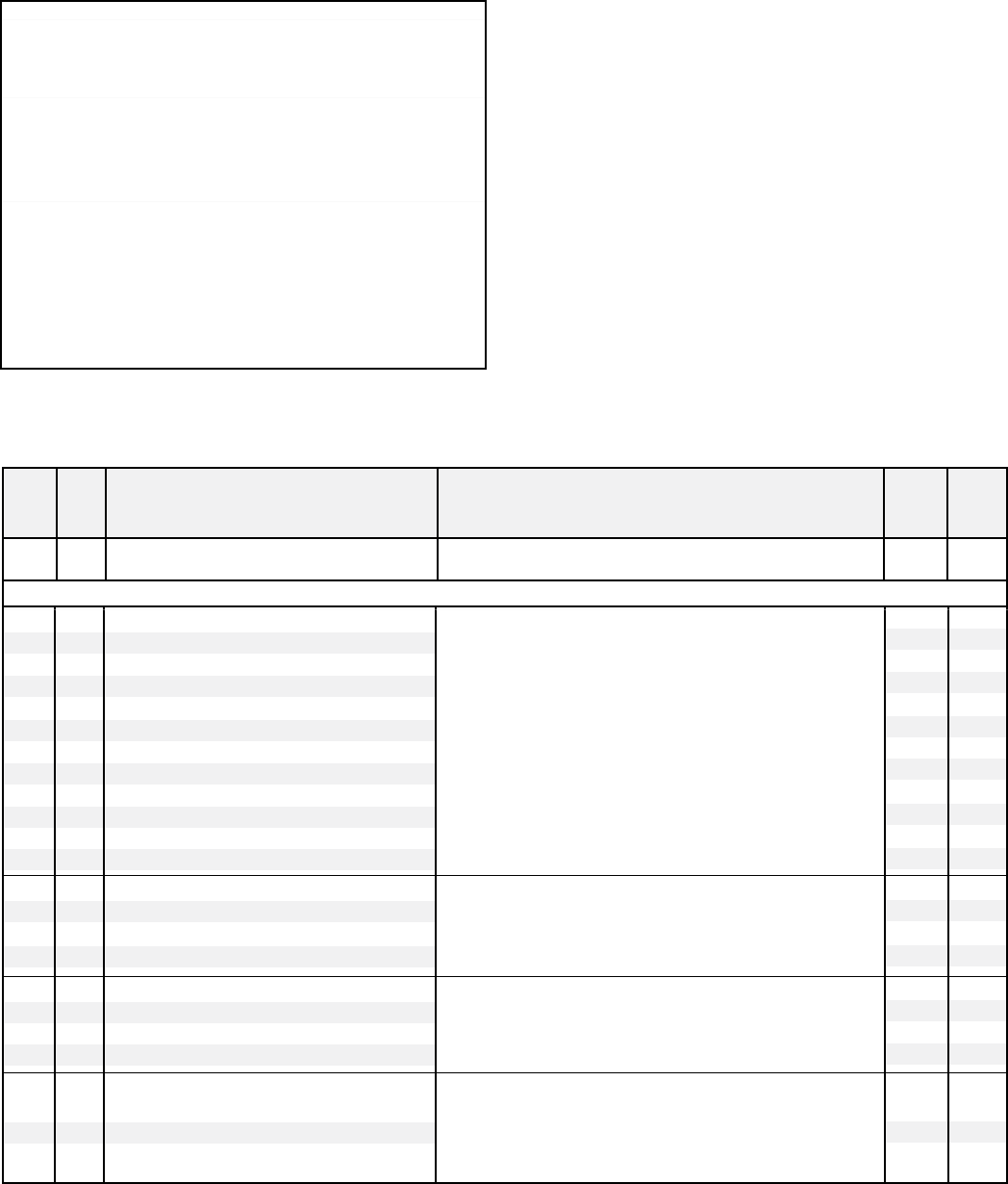
FIGURE 15 - THE BEndIx® TRAILER REmOTE
dIAGnOSTIC UnIT
LED lights
illuminate
Diagnostic
Trouble Codes
(10 LEDs)
Parallel or Serial
Cable
J1708/J1587
or J1939
Lap Top Computer
PDM (RP-1210A)
FIGURE 14 - BEndIx ABS dIAGnOSTIC SOFTWARE
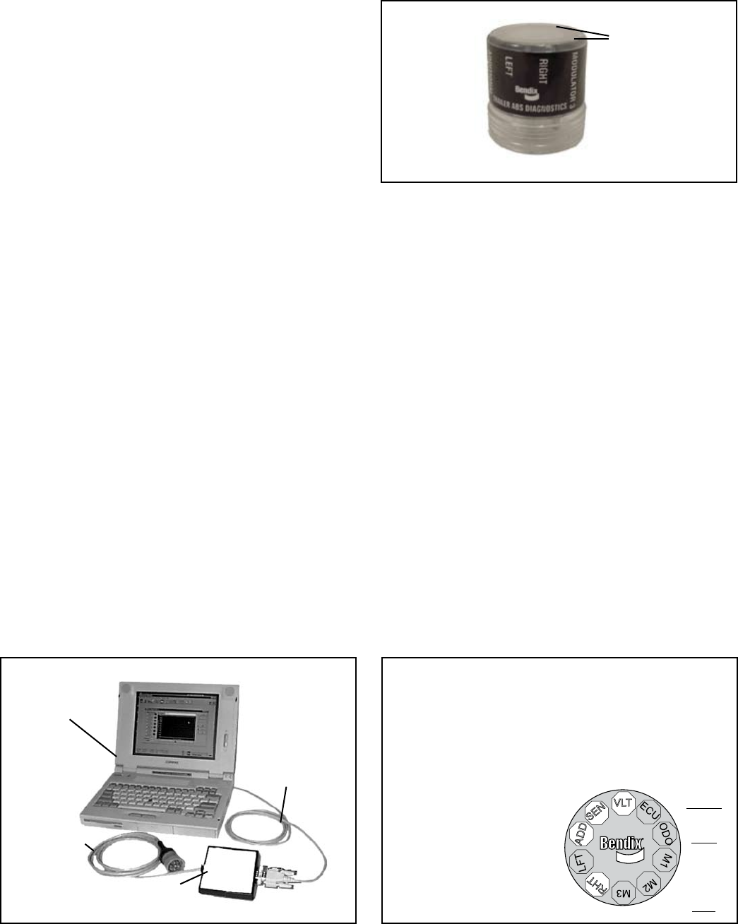
Bendix® TRDU™ (Trailer Remote Diagnostic Unit)
Tool
The Bendix® TRDU™ tool provides the technician with
a visual indication of Antilock Braking System (ABS)
component Diagnostic Trouble Code (DTC) information.
The TRDU™ tool is specically designed for use with
Bendix® Trailer ABS systems and Bendix makes no claims
for its operation and/or usability with other brands of trailer
ABS.
Features of the Bendix® TRDU™ Tool
The TRDU™ tool attaches to a 7-pin to 7-pin adapter (See
Figure 17) and then into the J560 of the towing vehicle.
The TRDU™ tool communicates across PLC.
The TRDU™ tool allows the technician to:
• Troubleshoot ABS system component problems using
Diagnostic Trouble Code reporting via LEDs.
• Reset Diagnostic Trouble Codes on Bendix® ABS ECUs
by holding a magnet over the reset of the TRDU™ tool
for less than 6 seconds.
• Initiate a self-conguration event Mode used by Bendix®
ABS ECUs by holding a magnet over the reset area for
greater than 6 seconds but less than 11 seconds.
LED Diagnostic Trouble Codes
VLT - Power
ECU - ABS Controller
SEN - Wheel Speed
Sensor
MOD1 - Modulator 1
MOD2 - Modulator 2
MOD3 - Modulator 3
LFT - Left
RHT - Right
ADD - Additional
ODO - Odometer
FIGURE 16 - dIAGnOSTIC TROUBLE COdES
Example: If the Diagnostic
Trouble Code is "Right
Additional Sensor", the
TRDU™ tool will display
one green and three red
LEDs
LEDs
Green
VLT
Blue
ODO
All
others
are
Red
14
How the Bendix® TRDU™ Tool Operates
When the TRDU™ tool is plugged into the adapter, and
the adapter/TRDU™ tool is installed between the trailer
connector and the J560 connector of the towing vehicle, all
the LEDs will illuminate, and the green LED will ash 4 times
to indicate communications have been established.
If the ABS ECU has no active Diagnostic Trouble Codes,
only the green LED will remain illuminated.
If the ABS ECU has at least one active Diagnostic
Trouble Code the TRDU™ tool displays the rst diagnostic
trouble code by illuminating the red LEDs, indicating the
malfunctioning ABS component and its location on the
vehicle. (See Figure 18.) If there are multiple diagnostic
trouble codes on the ABS system, the TRDU™ tool will
display one diagnostic trouble code rst, then once that
Diagnostic Trouble Code has been repaired and cleared,
the next code will be displayed.
The TRDU™ tool repeatedly blinks out the mileage stored
once communications have been established. By counting
the sequence of blinks and/or strobes on the blue LED
the odometer reading is given. See page 10 for more
details.
• VLT (Flashing indicates either over- or under-voltage
condition)
To pinpoint the root cause and to ensure the system
diagnostic trouble code is properly corrected the rst time,
additional troubleshooting may be necessary.
Bendix® TRDU™ Tool Reset Function
The magnetic reset switch is located by the letter "B" in
the Bendix logo on the top of the TRDU™ tool. Activation
requires a magnet with 30 gauss minimum.
The reset operations are:
1. If the magnet is held over the switch for less than 6
seconds the "clear diagnostic trouble codes" command
is sent.
2. If the magnet is held over the switch for more than 6
seconds, but less than 11 seconds, the Bendix® ABS
"self-conguration command" is sent.
Additionally, it is recommended at the end of any inspection
that the user switches off and restores the power to the
ABS ECU, then check the ABS Indicator Lamp operation
and TRDU™ tool to see if they indicate any remaining
Diagnostic Trouble Codes.
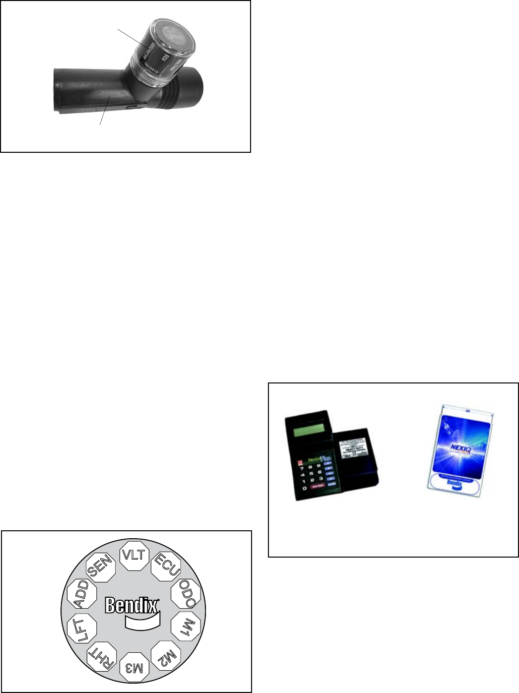
MPSI Bendix Cartridge
MPSI provides a Bendix cartridge for use with the Pro-
Link™ tool. For more information on the Bendix diagnostic
cartridge from MPSI, contact Bendix or refer to your local
authorized Bendix parts outlet.
PLC Diagnostic Tool
Diagnostic tools are available that detect the presence
of a PLC signal and perform further system diagnostics
directly on the power line. For more information on these
diagnostic tools, contact Bendix or refer to your local
authorized Bendix parts outlet.
FIGURE 19 - nExIq (mPSI) PRO-LInk TOOL
PC Card MPSI
Part Number
805013
Pro-Link
Heavy Duty
Multi Protocol
Cartridge
FIGURE 17 - TRdU™ TOOL And AdAPTER
Adapter
TRDU™ Tool
FIGURE 18 - TRdU™TOOL LEd LOCATIOnS
to Towing
Vehicle
J560
Connector
to Trailer
Connector
CONTACTING BENDIX
www.Bendix.com
The Bendix on-line troubleshooting guide will help you
determine the cause performance issues with your braking
system.
The Bendix on-line contacts directory will make it easy
for you to nd the Bendix contacts you need. From this
page, you can navigate to technical support contacts,
15
service engineers, Bendix account managers, international
contacts and more. Bendix.com is your complete Bendix
resource.
Bendix Technical Assistance Team
For direct personal technical support, call the Bendix
technical assistance team at:
1-800-AIR-BRAKE (1-800-247-2725),
Monday through Friday, 8:00 A.M. to 6:00 P.M. EST, and
follow the instructions in the recorded message.
Alternatively, you may e-mail the Bendix technical
assistance team at: tbs.techteam@bendix.com.
To better serve you, please record the following
information before you call the Bendix Tech Team,
or include this information in your e-mail:
• Bendix product model number, part number and
conguration.
• Vehicle make and model.
• Vehicle configuration. (Number of axles, tire size,
etc.)
• System performance symptoms: When do they
occur?
• What faults have been identied using LEDs, blink
codes or diagnostic tools?
• What troubleshooting/measurements have been
performed?
• What Bendix service data literature do you have or
need?
SERVICING THE TABS-6 MODULE
CAUTION: All TABS-6 modules are initially
defaulted to 2S/1M and may auto-congure to
another ABS conguration if additional sensors
and/or ABS modulators are detected. An incorrect
ABS conguration may cause fault indication or
degraded ABS performance. Before and after
activating a self-conguration, always check the
current ABS conguration by using blink code
diagnostics or a diagnostic tool.
Prior to performing service to the TABS-6 module, always
perform the following steps:
1. Follow all Safe Maintenance Practices including, but
not limited to, those on page 2 of this document.
2. Turn power off.
3. Drain the air pressure from all reservoirs.
4. Remove as much contamination as possible prior to
disconnecting electrical connections and air hoses.
5. Note the TABS-6 module's mounting position on the
vehicle.
REMOVING THE TABS-6 MODULE
1. Open the cover by sliding the locking tab to the left.
Retain the cover.
2. Disconnect the 5 or 18-pin ECU connector and the two
2-pin wheel speed sensor connectors.
3. Mark for reinstallation and then remove all air hoses
and plugs connected to the module.
4. Remove the module from the vehicle by removing the
mounting fasteners or by rotating the entire assembly
counter-clockwise from the tank mount.
SERVICE REPLACEMENT OF OTHER ABS
CONTROLLERS
The TABS-6 module is designed to be used as the
service replacement part for the Bendix® MC-12™,
MC-30™ and A-18™ trailer ABS controllers. When
controller service replacement parts are required, a
TABS-6 module and pigtail harness must replace the entire
MC-12™, MC-30™ or A-18™ controller assembly and pigtail
harness. When replacing an MCE-12™ controller, the
integral emergency function (EV-2™ valve) must be replaced
by a DC-4™ and TR-3™ valve combination. See pages 18-
21 for plumbing details. TABS-6 module kits are available
to replace all MC-12™, MC-30™ and A-18™ controller
assemblies and harnesses. For more information, contact
Bendix or your local authorized Bendix parts outlet.
1. Disconnect the power connector and wheel speed
sensors from the MC-12™ or MC-30™ controller pigtail
harness.
2. Remove all air hoses and plugs connected to the
unit.
3. Remove the MC-12™ or MC-30™ controller assembly
and pigtail from the vehicle by removing the mounting
bracket nuts or by rotating the entire assembly counter
clockwise from the tank nipple mount.
4. Install the new pigtail, starting at the power connector
and properly securing the harness every 18 inches to
the ECU location.
5. Next, refer to the Reinstallation of the TABS-6 Module
section.
REINSTALLATION OF THE TABS-6 MODULE
CAUTION! All TABS-6 module service replacement
parts are initially defaulted to 2S/1M and may auto-
congure to another ABS conguration if additional
sensors and/or ABS modulators are detected. An
incorrect ABS conguration may cause fault indication
or degraded ABS performance. Before and after
activating a self-conguration, always determine the
current ABS conguration by activating blink code
diagnostics.
Inspect the original mounting hardware: If it is in good
condition, it can be reused for installation. If replacement
16
hardware is needed, use grade-5 3/8-18 bolts, nuts and
lock washers for the frame-mount unit, or a schedule 80
(heavy gauge steel) ¾" nipple for the tank-mount unit.
Inspect the location selected for installation and clean as
necessary.
NOTE: Inspect all components, including the
replacement trailer ABS module, for any external
damage, such as cracked valve ports, electronic
housings, etc. Any components found to be damaged
should not be installed on the vehicle and must be
replaced.
1. Position and secure the unit in the original mounting
orientation (the exhaust port must point straight
down):
For tank-mount modules: Install the nipple tting into
the modulator-valve supply port. Then rotate the entire
assembly into the tank port until secure. Over-torquing
of the tank nipple could cause damage to the valve
body.
For frame-mount modules: Torque the mounting nuts
to 180-220 in-lbs.
2. Reconnect all air hoses and plugs to the module.
Depending on the installation, additional plugs may be
necessary. Make certain that no thread sealing material
enters the valve. All air hoses and ttings should be
checked for leaks prior to returning the vehicle to
service.
3. Reconnect the ECU and wheel speed sensor electrical
connectors to the unit. Apply a moderate amount of
non-conductive electrical grease to each connector pin
before reconnecting.
4. The new TABS-6 module may need to be recongured
for proper operation. See page 8.
5. Leakage and Operational Tests must be performed
before returning the vehicle to service.
LEAKAGE AND OPERATIONAL TESTS
1. Before performing leak tests, block the wheels.
2. Fully charge air brake system and verify proper brake
adjustment.
3. Make several trailer brake applications and check for
prompt application and release at each wheel.
4. Check the module, modulator valve(s) and all air hose
ttings for leakage using a soap solution:
Check the ABS solenoid body with the trailer service
brakes fully applied. If leakage is excessive, more
than a single 1" bubble within 1 minute, replace the
module.
Check the relay exhaust port with the trailer service
brakes released to be sure that leakage is less than
a single 1" bubble within 3 seconds. If excessive
leakage is detected at the relay exhaust port, perform
the following test before replacing the module:
• Apply the trailer spring brakes. Recheck for leakage
around the relay exhaust port. If the exhaust port
stops leaking, this indicates a leak between the
emergency and service sides of the spring brake
chamber. However, if the relay exhaust port
continues to leak excessively, replace the TABS-6
module.
5. Apply power and monitor the power-up sequence to
verify proper system operation. See page 6.
6. Determine the current ABS conguration by activating
blink code diagnostics or using a diagnostic tool. If
necessary, reset the ABS conguration and allow the
module to auto-congure. See page 8.
7. Calibrate and set odometer parameters if necessary
using a diagnostic tool. Refer to the Odometer Function
section on page 8.
8. Where a safe location (e.g. restricted access area
or test track) is available, it is possible to road test
the ABS function by making an abrupt stop from a
vehicle speed of about 20 MPH to check for proper
function. The wheels should not enter a prolonged lock
condition and ABS function should be audible. It is the
responsibility of the technician to perform this test in a
safe location.
ABS WIRING
All connector leads of the TABS-6 module pigtail harness
are weather sealed at the connector interface and are
clearly labeled for proper installation.
Bendix provides over-molded versions of the TABS-6
wiring harness and Bendix recommends that the complete
harness be replaced if corrosion or damage occurs.
When troubleshooting ABS wiring, some general rules
should be followed where applicable.
1. Check all wiring and connectors to ensure they are
secure and free from visible damage (e.g. cuts,
abrasions, etc.).
2. Check for evidence of wire chang due to poor routing,
or poor securing, of wires.
3. Check connectors for proper insertion and locking.
4. Verify that the connector pins are properly greased with
a non-conductive electrical grease compound.
5. Connector terminals must not show signs of corrosion
or exposure to the environment.
6. Never pierce wire insulation when checking for
continuity.
7. Do not deform individual pins or sockets during probing
with a volt/ohm meter.
8. It is strongly recommended to properly secure all wiring
harness and sensor leads at least every 18 inches.
9. Apply a moderate amount of non-conductive electrical
grease to each connector pin before reconnecting.

17
FIGURE 20 - STAndARd TABS-6 mOdULE (5-PIn ECU COnnECTOR) ELECTRICAL SCHEmATIC - 2S/1m
FIGURE 21 - PREmIUm TABS-6 mOdULE (18-PIn ECU COnnECTOR) ELECTRICAL SCHEmATIC - 4S/3m
B
A
E
C
1
7
4
PREMIUM
TABS-6
GROUND
BRAKE LAMP VOLTAGE
ABS WARNING LAMP (AUX7)
SENSOR ADD. RIGHT SAR (+)
SENSOR ADD. RIGHT SAR (-)
MOD2 RELEASE
MOD1/2 COMMON
MOD2 HOLD
MOD3 RELEASE
MOD3 COMMON
MOD3 HOLD
SENSOR ADD. LEFT SAL (+)
SENSOR ADD. LEFT SAL (-)
J1587 (B)
J1587 (A)
J1587 GROUND
J1587 VOLTAGE (AUX6) 2
13
1
7
14
8
16
4
10
15
3
9
17
11
5
12
6
18
2
1
2
1
1
2
3
1
2
1
2
1
2
1
2
1
2
3
SENSOR
RIGHT SR
SENSOR
LEFT SL
SENSOR ADD.
RIGHT SAR
SENSOR ADD.
LEFT SAL
7-WAY SAE J560
CONNECTOR
6-WAY SAE J1587
CONNECTOR
MODULATOR VALVE
MOD2
MODULATOR VALVE
MOD3
TRAILER-MOUNTED
A
BS WARNING LAMP
IGNITION VOLTAGE
SENSOR RIGHT SR (+)
SENSOR RIGHT SR (-)
SENSOR LEFT SL (+)
SENSOR LEFT SL (-)
Trailer
ABS
Controller
Troubleshooting: Electrical Schematics
18
Troubleshooting: System Schematics
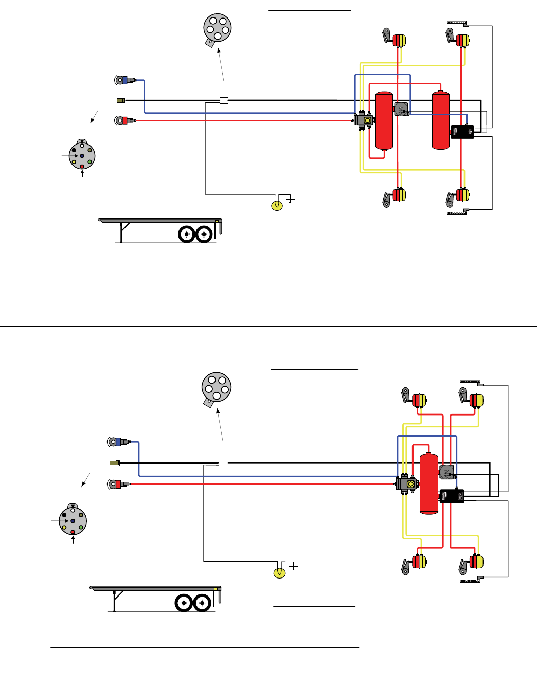
2S/1M - AXLE
CONTROL
Trailer
Chassis
Harness
ABS
Dual Axle Trailer
Bendix
SR-5™ Trailer
Spring Brake
Valve
Trailer ABS
Pigtail
Harness
5-PIN
CONNECTOR
Ignition
Power
Brake
Light
Power
Ground
7-PIN
CONNECTOR
SUPPLY
LINE
CONTROL
LINE
A Brake
Light Power
B Ignition
Power
C NC
D Warning
Lamp
E Ground
C
E
B
A
D
Bendix
®
TABS-6
Trailer
ABS
Module
ABS
Indicator Lamp
TABS
Bendix WS-24™
Wheel Speed
Sensor "SR"
Bendix WS-24™
Wheel Speed
Sensor "SL"
Right -
“Curb-Side”
Left -
“Road-
S
ide”
®
®
®
19
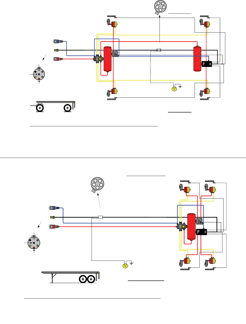
2S/2M - AXLE CONTROL
Trailer
Chassis Harness
ABS
Dual Axle Trailer
Trailer ABS
Pigtail Harness
5-PIN
CONNECTOR
Ignition
Power
Brake Light
Power
Ground
7-PIN
CONNECTOR
SUPPLY
LINE
CONTROL
LINE
A Brake Light Power
B Ignition Power
C NC
D Warning Lamp
E Ground
C
E
B
A
D
ABS Light
TABS-6
Trailer
ABS
Module
“MOD1”
TABS
SR-5
™
Trailer
Spring Brake
Valve
Bendix®
BR9235
™
Modulator
Relay
Valve
“MOD2”
WS Sensor
"SR"
WS Sensor
"SL"
Installation Guidelines for the TABS-6 2S/2M Axle ABS Configuration:
o MOD1 (TABS-6 ABS Unit) controls the left “road-side” wheel(s) of a primary axle(s).
o MOD2 (
Bendix
®
BR9235
™
Modulator Unit) controls the wheels of an additional axle(s).
o SL & SR (Primary Sensors) senses wheels on the primary axle (always on ground) that MOD1 controls.
o For lift axle applications, MOD2 controls the wheels for the lift-able axle
Right - “Curb-Side”
Left - “Road-Side”
2S/2M - SIDE CONTROL
Trailer
Chassis Harness
ABS
Dual Axle Trailer
Trailer ABS
Pigtail Harness
5-PIN
CONNECTOR
Ignition
Power
Brake Light
Power
Ground
7-PIN
CONNECTOR
SUPPLY
LINE
CONTROL
LINE
A Brake Light Power
B Ignition Power
C NC
D Warning Lamp
E Ground
C
E
B
A
D
ABS Light
“MOD1”
TABS
“MOD2”
WS Sensor
"SR"
WS Sensor
"SL"
Installation Guidelines for the TABS-6 2S/2M Side ABS Configuration:
o MOD1 (TABS-6 ABS Unit) controls the left “road-side” wheel(s) of a primary axle(s).
o MOD2 (Bendix
®
BR9235
™
Modulator Unit) controls the right “curb-side” wheel(s) of a primary axle(s).
o For lift axle applications, SL & SR (Primary Sensors) senses the wheels of the stationary, non lift-able axle
Right - “Curb-Side”
Left - “Road-Side”
SR-5
™
Trailer
Spring Brake
Valve
Bendix
®
BR9235
™
Modulator
Relay Valve
TABS-6
Trailer
ABS Module
Troubleshooting: System Schematics (continued)
20
4S/2M - SIDE CONTROL
Trailer
Chassis Harness
ABS
Dual Axle Trailer
Trailer ABS
Pigtail Harness
5-PIN
CONNECTOR
Ignition
Power
Brake Light
Power
Ground
7-PIN
CONNECTOR
SUPPLY
LINE
CONTROL
LINE
A Brake Light Power
B Ignition Power
C NC
D Warning Lamp
E Ground
C
E
B
A
D
ABS Light
“MOD1”
TABS
“MOD2”
WS Sensor
"SR"
WS Sensor
"SL"
WS Sensor
"SAR"
WS Sensor
"SAL"
Installation Guidelines for the TABS-6 4S/2M Side ABS Configuration:
o MOD1 (TABS-6 ABS Unit) controls the left “road-side” wheel(s) of a primary axle(s).
o MOD2 (Bendix
®
BR9235
™
Modulator Unit) controls the right “curb-side” wheel(s) of a primary axle(s).
o SL & SR (Primary Sensors) are connected to the dedicated 2-pin connector on the TABS-6 ECU.
o SAL & SAR (Additional Sensors) are connected to the 18-pin connector on the TABS-6 ECU.
o For lift axle applications, SAL & SAR (Additional Sensors) senses the wheels of the lift-able axle
Right - “Curb-Side”
Left - “Road-Side”
SR-5™ Trailer
Spring Brake
Valve
Bendix
®
BR9235™
Modulator
Relay Valve
TABS-6
Trailer
ABS Module
4S/2M - AXLE CONTROL
Trailer
Chassis Harness
Trailer ABS
Pigtail Harness
WS Sensor
"SR"
5-PIN
CONNECTOR
Ignition
Power
Brake Light
Power
Ground
7-PIN
CONNECTOR
SUPPLY
LINE
CONTROL
LINE
A Brake Light Power
B Ignition Power
C NC
D Warning Lamp
E Ground
C
E
B
A
D
ABS Light
WS Sensor
"SL"
“MOD1”
TABS
“MOD2”
WS Sensor
"SAR"
WS Sensor
"SAL"
Full Trailer
ABS
Installation Guidelines for the TABS-6 4S/2M Axle ABS Configuration:
o MOD1 (TABS-6 ABS Unit) controls the left “road-side” wheel(s) of a primary axle(s).
o MOD2 (Bendix
®
BR9235
™
Modulator Unit) controls the wheels of an additional axle(s).
o SL & SR (Primary Sensors) senses wheels on the primary axle (always on the ground) that MOD1 controls, and
are connected to the dedicated 2-pin connector on the TABS-6 ECU.
o SAL & SAR (Additional Sensors) senses the wheels that MOD2 controls, and are connected to the 18-pin
connector on the TABS-6 ECU.
o For lift axle applications, MOD2 controls the wheels for the lift-able axle
Right -
“Curb-Side”
Left -
“Road-Side”
SR-5™ Trailer
Spring Brake
Valve
Bendix
®
BR9235™
Modulator
Relay Valve TABS-6
Trailer
ABS
Module
Troubleshooting: System Schematics (continued)
21
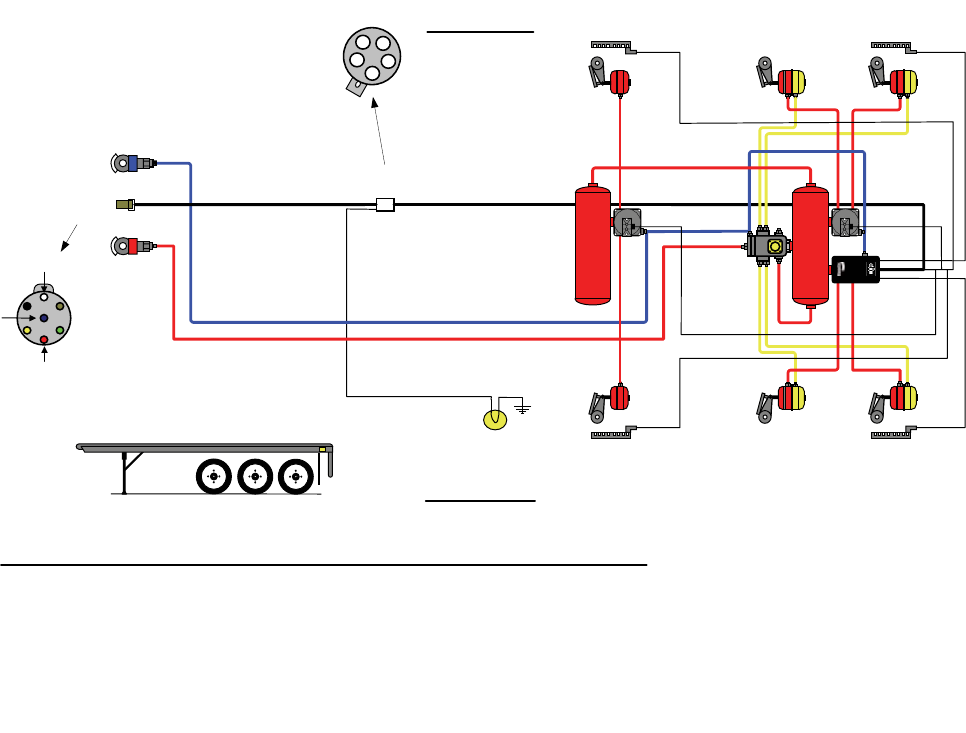
ABS
Tri-Axle Trailer
4S/3M - SIDE/AXLE CONTROL
Trailer
Chassis Harness
Trailer ABS
Pigtail Harness
5-PIN
CONNECTOR
Ignition
Power
Brake Light
Power
Ground
7-PIN
CONNECTOR
SUPPLY
LINE
CONTROL
LINE
A Brake Light Power
B Ignition Power
C NC
D Warning Lamp
E Ground
C
E
B
A
D
ABS Light
“MOD1"
TABS
“MOD2”
WS Sensor
"SR"
WS Sensor
"SL"
WS Sensor
"SAR"
WS Sensor
"SAL"
“MOD3”
Installation Guidelines for the TABS-6 4S/3M Side/Axle ABS Configuration:
o MOD1 (TABS-6 ABS Unit) controls the left “road-side” wheel(s) of a primary axle(s).
o MOD2 (Bendix
®
BR9235
™
Modulator Unit) controls the right “curb-side” wheel(s) of a primary axle(s).
o MOD3 (Bendix
®
BR9235
™
Modulator Unit) controls the wheels of an additional axle(s).
o SL & SR (Primary Sensors) senses wheels on the primary axle (always on the ground) that MOD1 controls, and
are connected to the dedicated 2-pin connector on the TABS-6 ECU.
o SAL & SAR (Additional Sensors) senses the wheels that MOD3 controls, and are connected to the 18-pin
connector on the TABS-6 ECU.
o For lift axle applications, MOD3 controls the wheels for the lift-able axle
Right -
“Curb-Side”
Left -
“Road-Side”
SR-5
™
Trailer
Spring Brake
Valve
Bendix
®
BR9235
™
Modulator
Relay Valve
TABS-6
Trailer
ABS Module
Bendix
®
BR9235
™
Modulator
Relay Valve
Troubleshooting: System Schematics (continued)
22
Troubleshooting Flowcharts
Diagnostic trouble code information can be retrieved from
the TABS-6 module by using blink code diagnostics, or a
diagnostic tool. The following troubleshooting ow charts
will help the technician isolate the cause of the fault and
conrm whether the fault resides in the component, wiring
or connectors.
Troubleshooting should always begin by observing the
dash or trailer-mounted ABS indicator lamp during the
TABS-6 module's power-up sequence. If it is necessary
to make electrical measurements, always begin by taking
voltage and resistance measurements at the 5 or 18-pin
ECU pigtail harness connector.
Once the circuit fault is found, isolate the area needing
repair by repeating the measurements at all connections
in the affected circuit towards the modulator, wheel speed
sensor, etc.
No voltage or resistance measurements are to be made on
the bulkhead connector pins of the module.
Troubleshooting Flowcharts
Section A : (Power-Up Sequence)
Trailer-Mounted ABS Indicator Lamp . . . . . . . Page 23
Section B: (Power-Up Sequence)
Dash-Mounted ABS Indicator Lamp . . . . . . . . Page 24
Section C: Diagnostic Trouble Code (DTC) Blink
Code Quick Reference . . . . . . . . . . . . . . . . . . . Page 25
Section D: Diagnostic Trouble Code
TRDU™ Tool LED Quick Reference . . . . . . . . . Page 26
Section E: Troubleshooting the Trailer-Mounted
ABS Indicator Lamp Circuitry . . . . . . . . . . . . . Page 27
Section F: Troubleshooting the Power Supply . . . . . . . . . Page 28
Section G: Troubleshooting the WS-24™ Wheel
Speed Sensors ......................... Page 29
Section H: Troubleshooting the BR9235™ Modulator
Relay Valves........................... Page 30

23
SECTION A: (POWER-UP SEQUENCE)
TRAILER-MOUNTED ABS INDICATOR LAMP
24
SECTION B: (POWER-UP SEQUENCE)
DASH-MOUNTED ABS INDICATOR LAMP

25
SECTION C: DIAGNOSTIC TROUBLE CODE (DTC)
BLINK CODE QUICK REFERENCE
To Read/Clear Diagnostic Troubleshooting Codes (DTCs):
1. Apply constant power to the trailer (ignition switch).
2. Within 15 seconds, apply/release the brake pedal at 1 second intervals:
(a) 3 times for displaying Active DTCs.
(b) 4 times for displaying Inactive DTCs.
(c) 5 times for clearing Active DTCs.
3. After 5 seconds delay, the blink codes will be displayed.
4. Observe the trailer-mounted ABS indicator lamp and record blink code(s).
5. Refer to blink code chart for description.
6. After making repairs and clearing Active DTCs, verify lamp is no longer illuminated.
1st Blink Code 2nd Blink Code
Code Location Code Description Repair Information
1 All 1 No Diagnostic Trouble Codes • System fully operational ‑ no faults detected
2 Sensor SL 1 Sensor signal valid ‑ large air gap • Go to Section G ‑ Dynamic WSS DTCs
3 Sensor SR 2 Sensor signal valid ‑ loss of signal • Go to Section G ‑ Dynamic WSS DTCs
4 Sensor SAL 3 Sensor signal valid ‑ noisy • Go to Section G ‑ Dynamic WSS DTCs
5 Sensor SAR 4 Sensor shorted or open • Go to Section G ‑ Static WSS DTCs
5 Tirediameteroutofrange •Verifycorrecttiresize,propertireination&correct
number of exciter ring teeth. Verify that the ECU
has the proper tire size settings.
6 Sensorcongurationerror •VerifycorrectABSconguration.Ifneeded,resetto
thedefaultABScongurationandpower-upto
initiateauto-conguration.
6 Power 1 Over-voltage •GotoSectionF-PowerSupply
2 Low-voltage •GotoSectionF-PowerSupply
3 Excessivepowerlineresistance •GotoSectionF-PowerSupply
7 ValveMOD1 1 Holdsolenoid(AUX)shortedoropen •GotoSectionH-ABSModulatorDTCs
8 ValveMOD2 2 Releasesolenoid(AUX)shortedoropen •GotoSectionH-ABSModulatorDTCs
9 ValveMOD3 3 ABSmodulatordynamicerror •GotoSectionH-ABSModulatorDTCs
4 Valvecongurationerror •VerifycorrectABSconguration.Ifneeded,resetto
thedefaultABScongurationandpower-upto
initiateauto-conguration.
10 Common 1 ValveMOD1/2low-sideswitchshortedtoground •GotoSectionH-ABSModulatorDTCs
2 ValveMOD3(AUX)low-sideswitchshortedtoground •GotoSectionH-ABSModulatorDTCs
3 ABSmodulatordynamicerror-allvalves •GotoSectionH-ABSModulatorDTCs
4 Excessive ABS activity • Go to Section G ‑ Dynamic WSS DTCs
11 ECU 1 ECU internal error • Check for damaged or corroded connectors. Check
fordamagedwiring.Afterrepairsorifnoissues
found,thenclearfaults.Iffaultsreturn,replacethe
module.
2 ECUcongurationerror •VerifycorrectABSconguration.Ifneeded,resetto
thedefaultABScongurationandpower-upto
initiateauto-conguration.
12 Diagnostics 1 J1587diagnostics(AUX6)shortedoropen •Checkforcorroded/damagedwiringorconnectors
betweentheECUandJ1587Diagnostic(AUX6).
Replace/repairJ1587Diagnostic(AUX6)wiringor
components as required.
13 IndicatorLamp 1 ABSlamp(AUX7)shortedoropen •GotoSectionE-TrailerABSIndicatorLamp

26
SECTION D: DIAGNOSTIC TROUBLE CODE (DTC)
TRDU™ TOOL LED QUICK REFERENCE
ODO
M1
Power
System OK - A solid green VLT LED indicates proper
voltage is reaching the module. If no red LEDs are on,
then no DTC's are detected.
If the ABS indicator lamp is on with no red LEDs, Go To
Section E, page 27.
Voltage Out of Range - A flashing green VLT LED
indicates ECU voltage below 8.0 VDC or above 16.0
VDC. The VLT LED will flash until power is brought into
normal range. Go to Section F, page 28.
No Voltage - When the VLT LED is off, the module is
receiving very low or no voltage, or there is no
communication to TRDU. The ECU LED may be on in
this case. Go to Section F, page 28.
Wheel Speed Sensor DTC
Static DTCs
Dynamic DTCs
The red SEN LED is on to indicate a DTC with a wheel
speed sensor. The example above shows the LEDs
illuminated when there is an additional right sensor
(SAR) DTC.
Troubleshooting and repair are the same for a DTC on
any wheel speed sensor. The indicated sensor DTC
may be static or dynamic.
are related to wiring or component failures
such as open or short circuits.
are related to abnormal wheel speed
signals or behaviors.
Go To Section G, page 29.
ABS Modulator DTC
Static DTCs
Dynamic modulator DTCs
The red M1, M2 and/or M3 LED is on to indicate a DTC
with an ABS modulator. The example above shows the
LEDs illuminated when there is a DTC for a second ABS
modulator (MOD2).
The indicated modulator DTC may be static or dynamic.
are related to wiring or component failures
such as open or short circuits.
are related to abnormal
wheel speed behaviors during ABS.
Go to Section H, page 30.
ECU DTC
The red ECU LED is on to indicate a DTC internal to the
TABS-6 module. Reset the TRDU tool with a magnet. If
the DTC returns, replace the module.
If the red ECU LED is on and the green VLT LED is off,
the module may have very low voltage. In this case, go
to Section F.
™
Magnetic Reset - All LEDs will be on
while a magnet is held in place at the
RESET location near the “B” in Bendix.
When held for less than 6 seconds, the
DTCs are cleared. When held for more
than 6 seconds,the ABS configuration is
reset. If one or more LEDs do not illuminate,
replace the TRDU™ tool. Do not reset the
DTC codes until troubleshooting of the
indicated component is complete.
Odometer Mileage - The TRDU will
continously display the odometer
information (x1000) by flashing the
blue ODO LED. There will be a 20
second pause between ODO displays.
As an example: 152,431 miles will be
displayed as:
152 (x1000) ... or 1 blink (pause), 5
blinks (pause), 2 blinks.
Zeros are displayed by the blue ODO
LED twice.strobing

27
SECTION E: TROUBLESHOOTING THE TRAILER-MOUNTED
ABS INDICATOR LAMP CIRCUITRY
Looking into
Standard TABS-
6 Module Wire
Harness (Pin D ABS
Indicator Lamp)
Looking into Premium
TABS-6 Module Wire
Harness (Pin 5 ABS
Indicator Lamp)
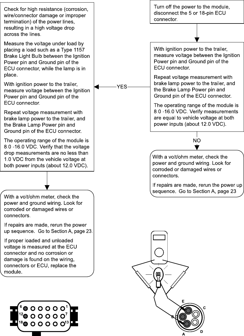
28
SECTION F: TROUBLESHOOTING THE
POWER SUPPLY
Measure the loaded
voltage across a type
1157 brake light bulb.
Looking into Premium TABS-6 Module Wire Harness,
ECU Connector Measure:
Pin 6 (Ignition Power) to Pin 18 (ground) and
Pin 12 (Brake Light Power) to Pin 18 (ground)
Looking into Standard TABS-6 Module Wire Harness,
ECU Connector Measure:
Pin B (Ignition Power) to Pin E (ground) and
Pin A (Brake Light Power) to Pin E (ground)
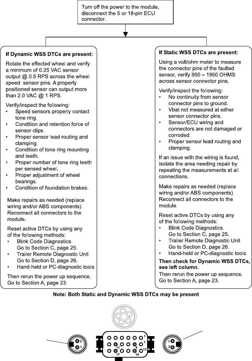
29
SECTION G: TROUBLESHOOTING THE
WS-24™ WHEEL SPEED SENSORS (WSS)
Looking into Premium TABS-6 Module Wire Harness
when Additional Wheel Speed Sensors are used:
SR Sensor
1 - Right (Curb) Sensor +
2 - Left (Curb) Sensor -
Looking into Wire Harness(es)
SL Sensor
1 - Left (Road) Sensor +
2 - Right (Road) Sensor -
SAR: 11 - Additional Right (Curb) Sensor +
17 - Additional Right (Curb) Sensor -
SAL: 8 - Additional Left (Road) Sensor +
14 - Additional Left (Road) Sensor -

30
SECTION H: TROUBLESHOOTING THE
MODULATOR RELAY VALVES
Pin 10 is MOD3 release
Pin 4 is MOD3 Common
Pin 16 is MOD3 Hold
Looking into Modulator
Connector Pins:
Pin 1 (Release)
Pin 2 (Common)
Pin 3 (Hold)
Looking into ECU
Connector:
Premium TABS-6 Module Wire Harness for BR9235™
Modulator Valve Connector
(Optional)
Pin 9 is MOD2 release
Pin 3 is MOD2 Common
Pin 15 is MOD2 Hold
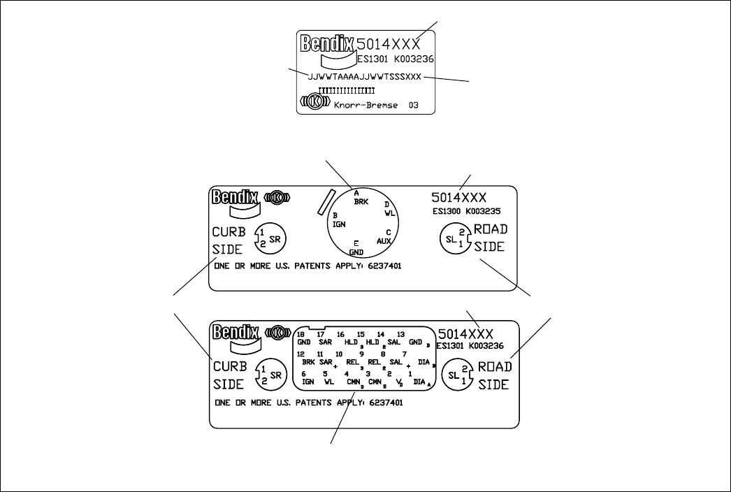
31
ECU Part Number Label
The external part number label is located on the relay valve portion of
the module. Label shown above is located under the removable cover
of the TABS-6 module. If the part number label is not readable or is
painted over, the ECU part number and revision can be read using a
diagnostic tool. The number of the initial software loaded on the ECU
is also indicated.
The module part number, and pin-out information is shown on the label
beneath the removable cover.
Software Revision Level
The current software revision number can be read using a diagnostic
tool.
Document Revision Level
Please visit Bendix.com to ensure you have the latest version of this
document.
FIGURE 22 - LABEL InFORmATIOn
Date of Manufacture Code
Number Showing
the Initial Software
Loaded
(Softwaremayberevised
on the production line or
intheeld.)
5-Pin ECU Pin-Out
Bendix Part Number
18-Pin ECU Pin-Out
2-Pin Sensor Pin-Out
and Routing Info
Bendix Part Number
2-Pin Sensor Pin-Out
and Routing Info
Bendix Part Number

32
BW2469 ©2007 Bendix Commercial Vehicle Systems LLC • All Rights Reserved • 3/07 • Printed in U.S.A.
