Bertazzoni MAS30 4 GAS XE 310825 User Manual To The Ca125236 5cff 45d9 9a7f 462d596b64c3
16935 1509067605 Mas30Gasxt-Installation,-Use-&-Care-Manual 16935_1509067605_MAS30GASXT-Installation,-Use-&-Care-Manual 16935_1509067605_MAS30GASXT-Installation,-Use-&-Care-Manual 33 staging productuploader-uploads 3:
16936 1509067603 Mas30Gasxe-Installation,-Use-&-Care-Manual 16936_1509067603_MAS30GASXE-Installation,-Use-&-Care-Manual 16936_1509067603_MAS30GASXE-Installation,-Use-&-Care-Manual 33 staging productuploader-uploads 3:
16935 1506431081 Mas30Gasxt-Installation,-Use-&-Care-Manual 16935_1506431081_MAS30GASXT-Installation,-Use-&-Care-Manual 16935_1506431081_MAS30GASXT-Installation,-Use-&-Care-Manual 33 staging productuploader-uploads 3:
16936 1506431079 Mas30Gasxe-Installation,-Use-&-Care-Manual 16936_1506431079_MAS30GASXE-Installation,-Use-&-Care-Manual 16936_1506431079_MAS30GASXE-Installation,-Use-&-Care-Manual 33 staging productuploader-uploads 3:
53299 1504045047 Mas30 4 Gas Installation, Use & Care Manual 53299_1504045047_MAS30 4 GAS Installation, Use & Care Manual 53299_1504045047_MAS30 4 GAS Installation, Use & Care Manual 33 staging productuploader-uploads 3:
User Manual: Bertazzoni MAS30 4 GAS XE to the manual
Open the PDF directly: View PDF ![]() .
.
Page Count: 32

1
INSTALLATION,USE&CAREMANUAL
FREESTANDINGGASRANGES
DIMENSIONS: 30’’ (762 mm)(W) x 253/16’’ (640 mm)(D) x36’’ (915 mm)(H)
MODELS
MAS30 4 GAS XT [M7S0GNA7X (2,5)AUA]
MAS30 4 GAS XE [M7S0GNA7X (2,5)AUG]
310825

2
BERTAZZONISpA
ViaPalazzina8
42016GuastallaRE
ITALY
WWW.BERTAZZONI‐ITALIA.COM
FromthedeskofthePresident
DearnewownerofaBertazzoniproduct,
Iwanttothankyouforchoosingoneofour
beautifulPROranges.Weknowthatyouhavemany
brandsandproductstochoosefromandweare
thrilledthatyouhavedecidedtotakeonwofyour
productsintoyourhome.
Wetakeasmuchprideinmakingourrangesaswe
hopeyouwillinowningthem.Myfamilystarted
manufacturingcookingappliancesin1882.Eachof
ourproductsisablendofItaliandesignfinessand
superiorappliancetechnology.Whilewecannot
replaceyouruniquetalentatcookingdelicious
recipesforyourself,yourfamilyandyourfriends,
wetryourbesttomakecookingeasier,more
effectiveandmorefun.
Ourappliancesaredesignedaccordingtothe
strictestsafetyandperformancestandardforthe
EuropeanandtheNorthAmericanmarket.We
followthemostadvancedmanufacturing
philosophy.Eachapplianceleavesthefactoryafter
thoroughqualityinspectionandtesting.Our
distributorsandourservicepartnersarereadyto
answeranyquestionsyoumayhaveregardinghow
toinstall,useandcareforyourBertazzoniproduct.
Thismanualwillhelpyoulearntousetheproduct
inthesafestandmosteffectivemannerandcare
foritsothatitmaygiveyouthehighestsatisfaction
foryearstocome.
Themanualalsoincludesdirectionsforthe
professionalinstallerthatwillinstalltheproductin
yourhome.Werecommendusingfactory‐trained
professionalsforthedelicatetaskofinstallingand
testingappliancesinyourhome.Pleasecall
CustomerServiceat(800)ifyouneedhelplocating
afactory‐trainedprofessionalinstallerinyourarea.
Pleasekeepthismanualforfutureuse.
Grazie!
3
TABLEOFCONTENTS
WARRANTYANDSERVICE........................................................................................................................................4
IMPORTANTSAFETYINFORMATION........................................................................................................................5
PRODUCTSPECIFICATIONS.......................................................................................................................................6
INSTALLATION
BEFOREINSTALLATION............................................................................................................................................7
INSTALLINGTHELEGS..............................................................................................................................................8
INSTALLINGTHEWORKTOPFRONTGUARD(OPTIONAL)...........................................................................................8
INSTALLINGTHEBACKGUARD..................................................................................................................................9
INSTALLINGTHEANTI‐TIPSTABILLTYDEVICE..........................................................................................................10
INSTALLATIONREQUIREMENTS.............................................................................................................................10
INSTALLATIONADJACENTTOKITCHENCABINETS...................................................................................................11
EXHAUSTHOODINSTALLATION.............................................................................................................................11
ELECTRICALCONNECTION......................................................................................................................................12
WIRINGDIAGRAM........................................................................................................................................................12
GASCONNECTION.................................................................................................................................................13
GASCONVERSION.................................................................................................................................................15
STEP1:PRESSUREREGULATOR....................................................................................................................................15
STEP2:SURFACEBURNERS..........................................................................................................................................16
STEP3:MAINOVENBURNER.......................................................................................................................................16
STEP4:BROILERBURNER.............................................................................................................................................17
STEP5:VISUALCHECKS................................................................................................................................................18
STEP6:MINIMUMFLAMEADJUSTMENT.....................................................................................................................19
INSTALLATIONCHECKLLST.....................................................................................................................................21
FINALPREPARATION.............................................................................................................................................21
USERMANUAL
ROOMVENTILATION.............................................................................................................................................22
SURFACEBURNERLAYOUT....................................................................................................................................22
SURFACECOOKING................................................................................................................................................23
CONTROLPANELSYMBOLS..........................................................................................................................................23
SURFACEBURNEROPERATION....................................................................................................................................23
TIPSFORUSINGBURNERSCORRECTLY........................................................................................................................24
TIPSFORUSINGPANSCORRECTLY...............................................................................................................................24
OVENCOOKING.....................................................................................................................................................25
CONTROLPANELSYMBOLS..........................................................................................................................................25
OVENSHELVES.............................................................................................................................................................26
GASOVENOPERATION.................................................................................................................................................26
CONVECTIONCOOKING...............................................................................................................................................27
COOKINGWITHTHEGASBROILER...............................................................................................................................28
MAINTAININGYOURRANGE..................................................................................................................................29
CLEANINGYOURRANGE........................................................................................................................................29
IMPORTANTAPPLIANCEINFORMATION................................................................................................................31
4
WARRANTYANDSERVICE
AllBertazzoniproductscarrya2yearpartsandlaborwarranty.
ServiceonallBertazzoniproductsshallbecarriedoutbyfactory‐trainedprofessionalsonly.
ForwarrantyservicepleasecontactCustomerServiceatthenumbersindicatedbelow.
CUSTOMERSERVICE
English/spanishhotline (866)905‐0010
French(800)561‐7625
Fax(714)428‐0040
Email
BERTAZZONIHELP@SERVICEPOWER.COM
Mailingaddress
SERVICEPOWER
1503SouthCoastdrive
Suite320
CostaMesaCA92626
REPLACEMENTPARTS
OnlyBertazzonireplacementpartsmaybeusedinperformingserviceontheappliance.
Replacementpartsareavailablefromfactoryauthorizedpartsdistributors.
APWagnerPHONE 716 961 7131 FAX716 856 4779
ReliablePartsPHONE 206 5758818 FAX206 5750910
CoastPHONE 800 821 0244 FAX604 321 6646
5
IMPORTANTSAFETYINFORMATION
PLEASEREADANDFOLLOWTHESEIMPORTANT
INSTRUCTIONSFORTHESAFETYOFYOURHOME
ANDOFTHEPEOPLELIVINGINIT.
SavethisManualforlocalelectricalinspector’s
use.
Readandsavetheseinstructionsforfuture
reference.
Observeallgoverningcodes,ordinancesand
regulations.
WARNING!
Iftheinformationinthismanualisnotfollowed
exactly,afireorexplosionmayresultcausing
propertydamage,personalinjuryordeath.
Donotstoreorusegasolineorotherflammable
substancesinthevicinityofthisoranyother
appliance.
Installationandservicemustbeperformedbya
qualifiedinstaller,serviceagencyorthegas
supplier.
InMassachusetts:Allgasproductsmustbe
installedbya"Massachusetts"licensedplumber
orgasfitter.A"T"handletypemanualgasvalve
mustbeinstalledinthegaslineconnectedtothis
appliance.
WHATTODOIFYOUSMELLGAS
Donotlightanyappliance.
Donottouchanyelectricalswitch.
Donotuseanyphoneinyourbuilding.
Immediatelycallyourgassupplierfroma
neighbor’sphone.Followthegassupplier’s
instructions.
Ifyoucannotreachyourgassuppliers,callthe
firedepartment.
WARNING!
Readthisinstructionbookletbeforeinstalling
andusingtheappliance.
Themanufacturerwillnotberesponsiblefor
anydamagetopropertyortopersonscausedby
incorrectinstallationorimproperuseofthe
appliance.
Themanufacturerreservestherighttomake
changestoitsproductswhenconsidered
necessaryanduseful,withoutaffectingthe
essentialsafetyandoperatingcharacteristics.
Thisappliancehasbeendesignedfornon‐
professional,domesticuseonly.
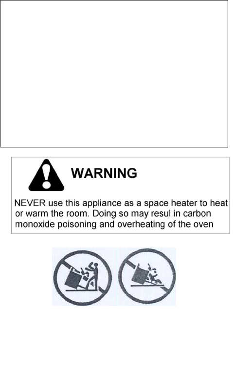
Donotusethisappliancetoheataroom.
Donotplaceanypotorpanontheopenoven
door.Thedoorismadeofglassanditcanbreak
ifloadedwithaweight.
Beforebeginninginstallation,pleasereadthese
instructionscompletelyandcarefully.
Donotremovepermanentlyaffixedlabels,
warnings,orplatesfromtheproduct.Thismay
voidthewarranty.‐Pleaseobservealllocaland
nationalcodesandordinances.
Pleaseensuretherangeisproperlygrounded.
Theinstallershouldleavetheseinstructionswith
theconsumerwhoshouldretainforlocal
inspector'suseandforfuturereference.
Theplugshouldalwaysbeaccessible.
Installationmustconformwithlocalcodesorin
theabsenceofcodes,theNationalFuelGasCode
NSIZ223.1‐latestedition.Electricalinstallation
mustbeinaccordancewiththeNational
ElectricalCode,ANIS/NFPA70‐latestedition
and/orlocalcodes.INCANADA:Installationmust
beinaccordancewiththecurrentCAN/CGA‐
B149.1NationalGasInstallationCodeor
CAN/CGA‐B149.2,PropaneInstallationCode
and/orlocalcodes.Electricalinstallationmustbe
inaccordancewiththecurrentCSAC22.1
CanadianElectricalCodesPart1and/orlocal
codes.
Installationofanygas‐firedequipmentshouldbe
madebyalicensedplumber.Amanualgasshut‐
offvalvemustbeinstalledinthegassupplyline
aheadoftheoveninthegasflowforsafetyand
easeofservice.
Warning!
This range can tip. Injury to persons could result.
Install anti-tip device shipped with range. See
Installation Instructions.
6
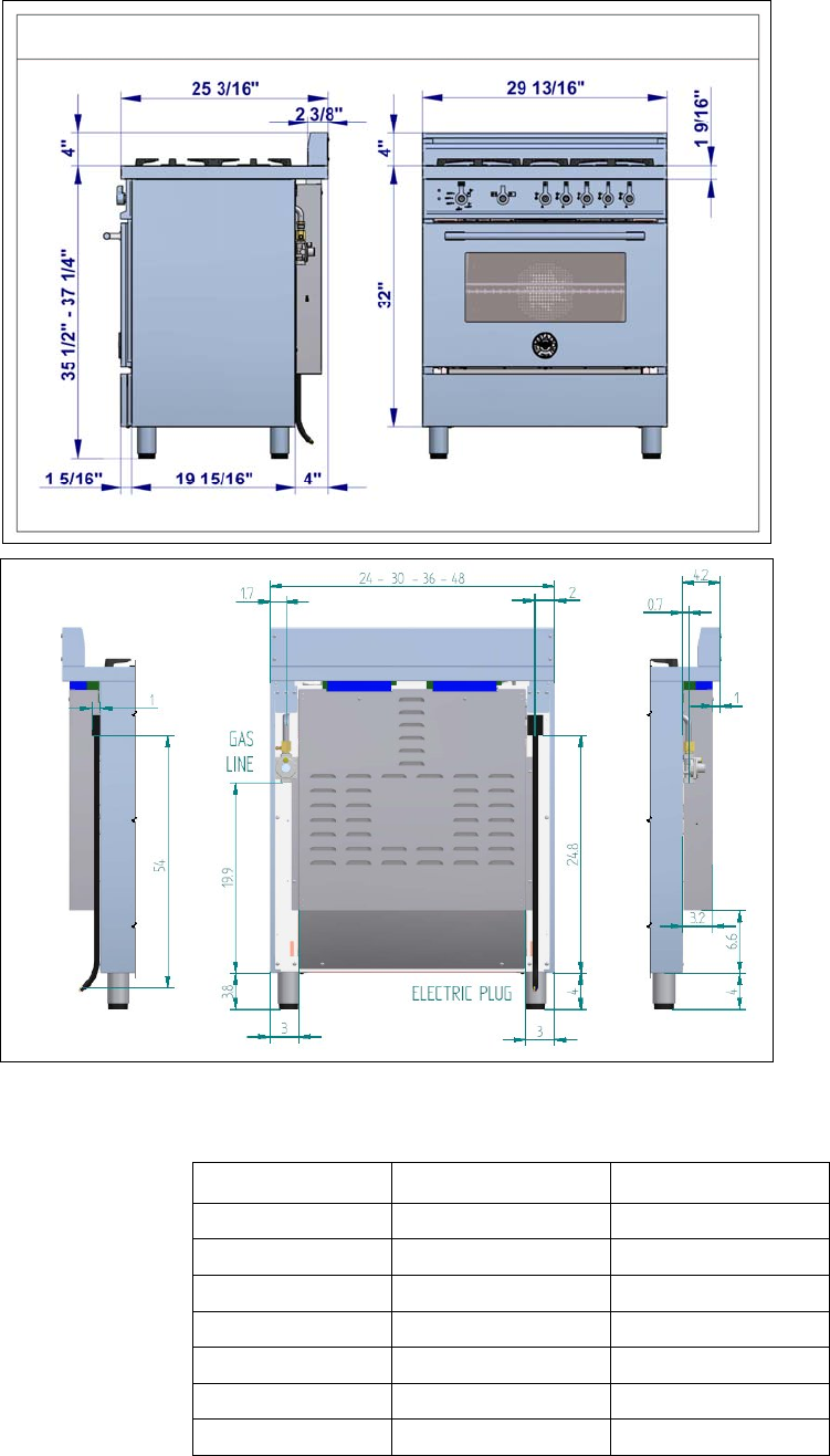
PRODUCTSPECIFICATIONS
Dimensions(insertdrawingsfront,sideandback
Weight
Burnerpower
NaturalgasLPgas
Auxiliary3730BTU/h3750BTU/h
Semi‐rapid6000BTU/h6300BTU/h
Rapid10400BTU/h11400BTU/h
Dualburner(inner)2730BTU/h2900BTU/h
Dualburner(outer)15000BTU/h16400BTU/h
Oven14500BTU/h14500BTU/h
broiler12000BTU/h12000BTU/h
7
BEFOREINSTALLATION
Thisapplianceshallonlybeinstalledbyan
authorizedprofessional.
Thisapplianceshallbeinstalledinaccordance
withthemanufacturer’sinstallationinstructions.
Thisappliancemustbeinstalledinaccordance
withthenorms&standardsofthecountrywhere
itwillbeinstalled.Theinstallationofthis
appliancemustconformtolocalcodesand
ordinances.Intheabsenceoflocalcodes,
InstallationsmustconformstoAmericanNational
Standards,NationalFuelGasCodeANSIZ223.1–
latestedition**orB149.1.
Theappliance,wheninstalled,mustbe
electricallygroundedinaccordancewithlocal
codesor,intheabsenceoflocalcodes,withthe
NationalElectricalCode,ANSI/NFPA70.
Iflocalcodespermit,aflexiblemetalappliance
connectionwiththenewAGAorCGAcertified
design,max.5feet(1,5m)long,½”I.D.is
recommendedforconnectingthisapplianceto
thegassupplyline.Donotbendordamagethe
flexibleconnectorwhenmovingtheappliance.
Thisappliancemustbeusedwiththepressure
regulatorprovided.Theregulatorshallbe
properlyinstalledinordertobeaccessiblewhen
theapplianceisinstalledinitsfinallocation.The
pressureregulatormustbesetforthetypeofgas
tobeused.Thepressureregulatorhas½”female
pipethread.Theappropriatefittingmustbe
determinedbasedonthesizeofyourgassupply
line,theflexiblemetalconnectorandtheshutoff
valve.
Theappliancemustbeisolatedfromthegas
supplypipingsystembyclosingitsindividual
manualshutoffvalveduringanypressuretesting
ofthegassupplypipingsystemattestpressures
equaltoorlessthan½psi(3.5kPa).
Allopeningandholesinthewallandfloor,back
andundertheapplianceshallbesealedbefore
installationoftheappliance.
Amanualvalveshallbeinstalledinanaccessible
locationinthegaslineexternaltotheappliance
forthepurposeofturningonorshuttingoffgas
totheappliance
WARNING!
Donotuseaerosolspraysinthevicinityofthis
appliancewhileitisinoperation
ROOMVENTILATION:Anexhaustfanmaybe
usedwiththeappliance;ineachcaseitshallbe
installedinconformitywiththeappropriate
nationalandlocalstandards.Exhausthood
operationmayaffectotherventedappliances;in
eachcaseitshallbeinstalledinconformitywith
theappropriatenationalandlocalstandards.
TYPEOFGAS
Thisapplianceisshippedfromthefactoryforuse
withnaturalgas.Forusewithpropanelpgas
pleasefollowtheconversionprocedure
describedonpg.17.Astepbystepconversion
procedureisalsoincludedwitheachsetoflpgas
nozzles.
GASPRESSURE
Themaximuminletgassupplypressureincoming
tothegasappliancepressureregulatoris20’’
watercolumn(5kPa).
Theminimumgassupplypressureforchecking
theregulatorsettingshallbeatleast1“w.c.(249
Pa)abovetheinletspecifiedmanifoldpressureto
theappliance(thisoperatingpressureis4”w.c.
(1.00kPa)forNaturalGasand11”w.c.(2.75kPa
forLPGas).
8
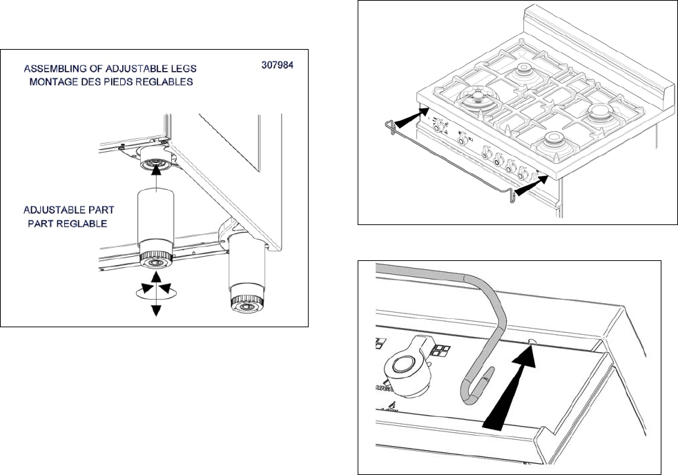
INSTALLINGTHELEGS
Bertazzonirangesmustbeusedonlywiththe
legsproperlyinstalled.
Fourheight‐adjustablelegsareshippedwiththe
rangeinthepolysterenecontainersituatedover
theappliance.
Beforeinstallingthelegs,positiontheappliance
nearitsfinallocationasthelegsarenotsuitable
formovingtheapplianceoverlongdistances.
Afterunpackingtherange,raiseitenoughto
insertthelegsintheappropriatereceptacles
situatedonthelowerpartoftheappliance.
Lowertherangegentlytokeepanyunduestrain
fromlegsandmountinghardware.Ifpossibleuse
apalletorliftjackinsteadoftiltingtheunit.
Adjustlegheighttothedesiredlevelbytwisting
theinsideportionofthelegassemblyuntilthe
properheightisreached.Checkwithalevelthat
thecooktopisperfectlylevel.
INSTALLINGTHEWORKTOP
FRONTGUARD
Toincreasetheclearancebetweenthefrontedge
oftheworktopandtheburnersitispossibleto
installtheworktopfrontguardshippedwiththe
appliance.
Toinstallthefrontguard,holditwiththepointed
edgeslookingup.Aligntheedgesofthe
frontguardwiththeappropriatereceptaclesin
thebottomoftheworktopandpressfirmlyuntil
thefrontguardissecurelyattachedtothe
worktop.
ATTENTION:onceinstalledthefrontguardmay
onlyberemovedbydisassemblingtheworktop.
Attemptingtoremovethefrontguardwithout
disassemblingtheworktopwillresultin
permanentdamagetotheworktop.
9
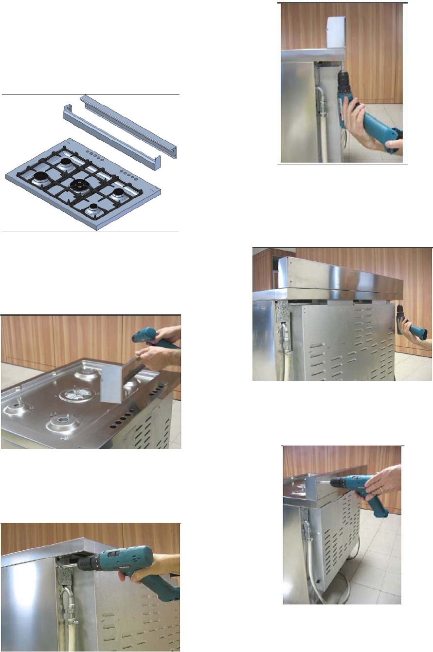
INSTALLINGTHEBACKGUARD
Thebackguardmustbeinstalledpriorto
operationoftheapplianceforappropriate
ventilationoftheovencompartment.
Thesuppliedbackguardisa2‐partassembly.The
boxalsocontainsasetofmetalscrewsfor
securingthebackguardtotheworktop.
Disassemblethebackguardandpositionthefront
partontheworktop.Alignthescrewholeswith
thecorrespondingholesatthebackofthe
worktop.
Iftheholesarenotaligned,partiallyloosenthe
bracketsattthebackoftheworktopasshown
below.
Installthefrontpartofthebackguardby
tighteningthe2centralscrewsfromthetopand
2lateralscrewsfromthebottom.
Positionthebackpartofthebackguardand
secureittotheworktoptightening4screwsfrom
thebottom.
Connectthebackandfrontpartoftheupstand.
Checkfortightassembly.
10
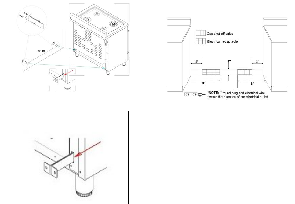
INSTALLINGTHEANTI‐TIPSTABILlTY
DEVICE
Theanti‐tipbracketshippedwiththerangemust
beproperlysecuredtotherearwallasshownin
thepircturebelow.
Theheightofthebracketfromthefloormustbe
determinedaftertherangelegshavebeen
adjustedtothedesiredheightandafterthe
rangehasbeenleveled.
Measurethedistancefromthefloortothe
bottomoftheanti‐tipbracketreceptacleonthe
backoftheappliance.
Positionthetwoanti‐tipbracketsonthewallat
thedesiredheightplus1/8"(0.32cm).The
bracketsmustbeplacedat2”5/16(6,0cm)from
thesideoftherange.Thedistancebetweenthe
twobracketis25”1/4(64,1cm).
Securethebracketstothewallwithappropriate
hardware.
Slidetherangeagainstthewalluntilthebrackets
arefullyinsertedintotheirreceptaclesonthe
backoftherange.
INSTALLATIONREQUIREMENTS
ELECTRICAL
Aproperly‐groundedhorizontally‐mounted
electricalreceptacleshouldbeinstallednohigher
than3"(7.6cm)abovethefloor,nolessthan2”
(5cm)andnomorethan8”(20,3cm)fromthe
leftside(facingproduct).
Checkalllocalcoderequirements.
GAS
Anagency‐approved,properly‐sizedmanualshut‐
offvalveshouldbeinstallednohigherthan3"
(7.6cm)abovethefloorandnolessthan2”(5
cm)andnomorethan8”(20.3cm)fromtheright
side(facingproduct).
Toconnectgasbetweenshut‐offvalveand
regulator,useagency‐approved,properlysized
flexibleorrigidpipe.Checkalllocalcode
requirements.
11
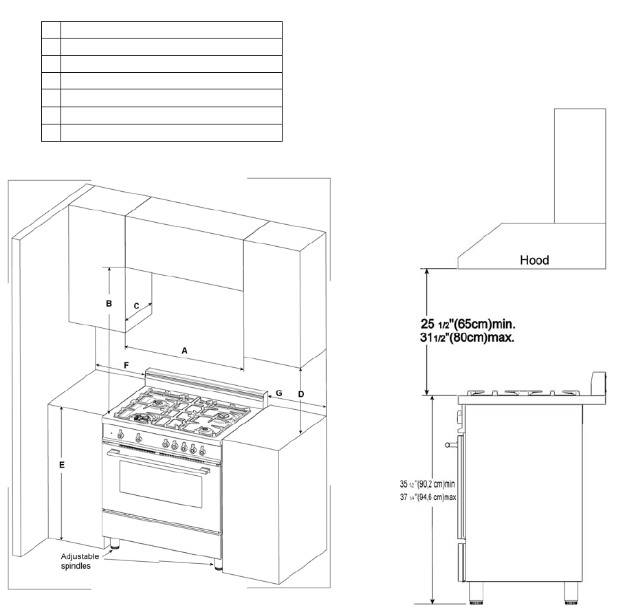
INSTALLATIONADJACENTTOKITCHEN
CABINETS
Thisrangemaybeinstalleddirectlyadjacentto
existingcountertophighcabinets(36"or91.5cm
fromthefloor).
Forthebestlook,theworktopshouldbelevel
withthecabinetcountertop.Thiscanbe
accomplishedbyraisingtheunitusingthe
adjustmentspindlesonthelegs.
ATTENTION:therangeCANNOTbeinstalled
directlyadjacenttokitchenwalls,tallcabinets,
tallappliances,orotherverticalsurfacesabove
36"(91.4cm)high.Theminimumsideclearance
insuchcasesis6"(15.2cm).
Wallcabinetswithminimumsideclearancemust
beinstalled18"(45.7cm)abovethecountertop
withcountertopheightbetween35½”(90.2cm)
and37¼”(94.6cm).Themaximumdepthofwall
cabinetsabovetherangeshallbe13"(33.0cm)
EXHAUSTHOODINSTALLATION
ThisrangewillbestperformwhenusedwithPRO
lineBertazzoniexhausthoods.Thesehoodshave
beendesignedtoworkinconjunctionwiththe
Bertazzonirangeandhavethesamefinishfora
perfectlook.
Formaximumperformance,theheightofthe
bottomofthehoodfromtheworktopshouldbe
between251/2"(65cm)and311/2"(80cm).
Thiswouldtypicallyresultinthebottomofthe
hoodbeing611/2"(156.2cm)to671/2"(171.5
cm)abovethefloor.Thesemeasurements
provideforsafeandefficientoperationofthe
hood.
Beforeinstallationoftheexhausthood,consult
localorregionalbuildingandinstallationcodes
foradditionalspecificclearancerequirements.
Refertotherangehoodinstallationinstructions
providedbythemanufacturerforadditional
information.
A 30” (76,2 cm)
B 36” (91,5 cm)
C 13” (33,0 cm)
D 18” (45,7 cm)
E 35”1/2(90,2 cm) / 37” ¼ (94,6 cm)
F 6” (15,2 cm)
G 6” (15,2 cm)
12
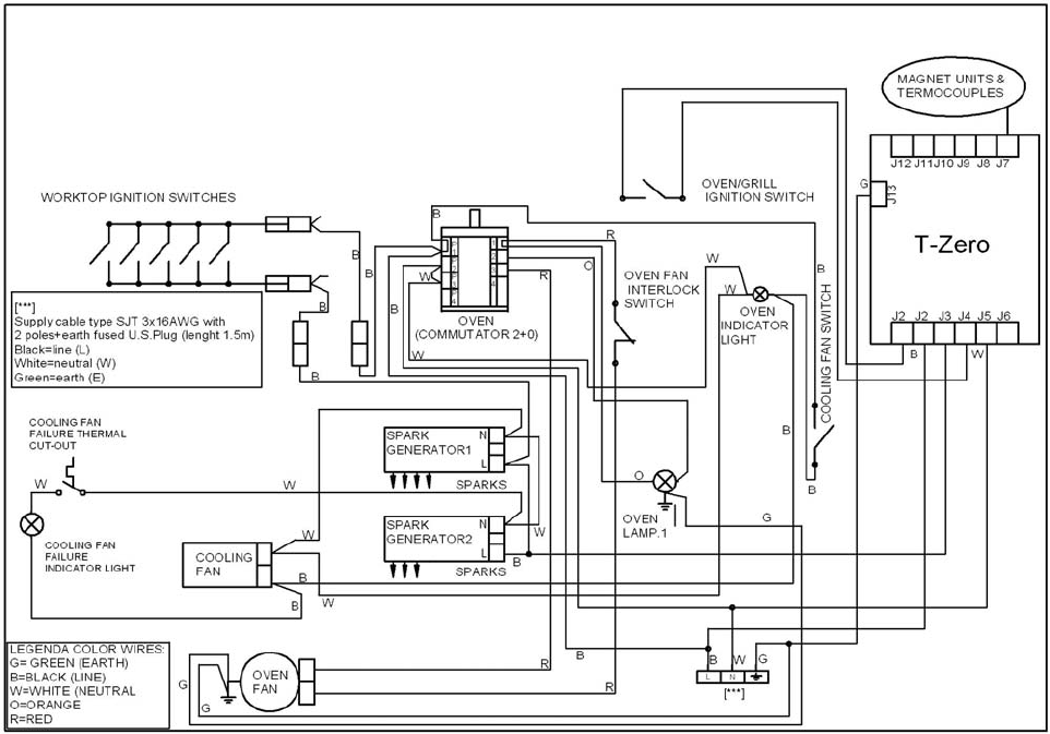
ELECTRICALCONNECTION
Thisunitismanufacturedforapolarized,
grounded120volt/60Hz,15ampsystem.
Electricpowerconsumptionisabout300W.
Theminimumof102VACisrequiredforproper
operationofgasignitionsystems.
Thecircuitmustbegroundedandproperly
polarized.
TheunitisequippedwitthaSJTpowercord.In
caseofreplacement,thepowercordshallbe
replacedwithoneofthesametype,sizeand
length.
ELECTRICALGROUNDING
Thisapplianceisequippedwithathree‐prong
plugforyourprotectionagainstshockhazardand
shouldbepluggeddirectlyintoaproperly
groundedsocket.Donotcutorremovethe
groundingprongfromthisplug.
WARNING!
ELECTRICALSHOCKHAZARD
Disconnectelectricalpoweratthecircuit
breakerboxorfuseboxbeforeinstallingthe
appliance.
Provideappropriategroundfortheappliance.
Usecopperconductorsonly.
Failuretofollowtheseinstructionscouldresult
inseriousinjuryordeath
CAUTION
Labelallwirespriortodisconnectingwhen
servicingcontrols.Wiringerrorscancause
improperanddangerousoperation.
Verifyproperoperationafterservicing.
WIRINGDIAGRAM
13
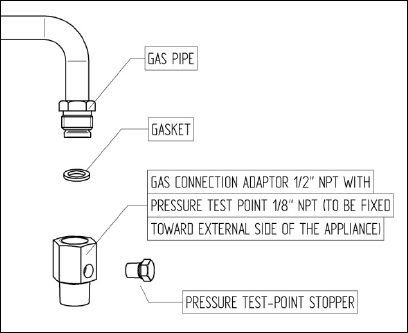
GASCONNECTION
Allgasconnectionsmustcomplywithnational
andlocalcodes.Thegassupplyline(service)
mustbethesamesizeorgreaterthantheinlet
lineoftheappliance.Thisrangeusesa1/2"NPT
inlet(seedrawingbelowfordetailsofgas
connection).Onallpipejointsuseappropriate
sealantresistanttogas.
ThisrangecanbeusedwithNaturalor
LP/Propanegas.Therangeisshippedfromthe
factoryforusewithnaturalgas.
ForLP/propanehouseholdinstallation,the
appliancemustbeconvertedbythedealer,bya
factory‐trainedprofessionalorbyaqualified
licensedplumberorgasservicecompany.
Gasconversionisimportantforsafeandeffective
useoftheappliance.Itistheresponsibilityofthe
dealerandtheowneroftherangetoperformthe
appropriategasconversionfollowingthe
directionsofthemanufacturer.
THEGASCONVERSIONPROCEDUREISDESCRIBED
INTHISMANUALANDINTHEPACKAGE
CONTAININGTHECONVERSIONNOZZLES
SHIPPEDWITHEVERYRANGE.
Pleaseprovidetheservicepersonwiththis
manualbeforeworkisstartedontherange.
WARNING!
DONOTUSEANOPENFLAMEWHENCHECKING
FORLEAKS!
Leaktestingoftheapplianceshallbeconducted
accordingtothemanufacturer'sinstructions.
Beforeplacingtheovenintooperation,always
checkforleakswithsoapywatersolutionor
otheracceptablemethod.
MANUALSHUT‐OFFVALVE
THISVALVEISNOTSHIPPEDWITHTHEAPPLIANC
ANDMUSTBESUPPLIEDBYTHEINSTALLER.
Themanualshut‐offvalvemustbeinstalledin
thegasservicelinebetweenthegashook‐upon
thewallandtheapplianceinlet,inaposition
whereitcanbereachedquicklyintheeventofan
emergency.
InMassachusetts:A'T'handletypemanualgas
valvemustbeinstalledinthegassupplylineto
thisappliance.
FLEXIBLECONNECTIONS
Incaseofinstallationwithflexiblecouplings
and/orquick‐disconnectfittings,theinstaller
mustuseaheavy‐duty,AGAdesign‐certified
commercialflexibleconnectorofatleast1/2"
(1.3cm)IDNPT(withsuitablestrainreliefs)in
compliancewithANSIZ21.41andZ21.69
standards.
InMassachusetts:Theunitmustbeinstalled
witha36"(3‐foot)longflexiblegasconnector.
InCanada:useCAN1‐6.10‐88metalconnectors
forgasappliancesandCAN1‐6.9M79quick
disconnectdeviceforusewithgasfuel.
PRESSURETEST‐POINTSTOPPERVALVE
Toavoidgasleaks,thepressuretest‐point
stoppervalveandgasketsuppliedwiththerange
mustbeinstalledonthegasfittingatthebackof
therangeaccordingtothediagrambelow.
14
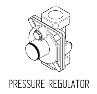
PRESSUREREGULATOR
Sinceservicepressuremayfluctuatewithlocal
demand,everygascookingappliancemustbe
equippedwithapressureregulatoronthe
incomingservicelineforsafeandefficient
operation.
Thepressureregulatorshippedwiththe
appliancehashastwofemalethreads½”NPT.
Theregulatorshallbeinstalledproperlyinorder
tobeaccessiblewhentheapplianceisinstalledin
itsfinalposition.
Manifoldpressureshouldbecheckedwitha
manometerandcomplywiththevaluesindicated
below:
Naturalgas4.0"W.c.P.
LP/Propane11.0"W.C.P.
Incominglinepressureupstreamfromthe
regulatormustbe1"W.c.P.higherthanthe
manifoldpressureinordertocheckthe
regulator.
Theregulatorusedonthisrangecanwithstanda
maximuminputpressureof1/2PSI(14.0"W.c.P.)
Ifthelinepressureexceedsthatamount,astep‐
downregulatorisrequired.
Theappliance,itsindividualshut‐offvalve,and
thepressureregulatormustbedisconnected
fromthegaslineduringanypressuretestingof
thatsystematpressuresinexcessof1/2psig
(3.45kPa).
TheindividuaLmanualshut‐offvalvemustbein
theOFFpositionduringanypressuretestingof
thegassupplypipingsystemattestpressures
equaltoorlessthan½psig(3.45kPa).
15
GASCONVERSION
WARNING!
Beforecarryingoutthisoperation,disconnect
theappliancefromgasandelectricity.
Gasconversionshallbeconductedbyafactory‐
trainedprofessional.
Callthecustomerservicehotlinetoidentifya
factory‐trainedprofessionalnearyourhome.
Thegasconversionprocedureforthisrange
includes6steps:
1. Pressureregulator
2. Surfaceburners
3. Mainovenburner
4. Broilerburner
5. Visualcheckspriortoclosureofovenbottom
panel
6. Adjustmentofminimumsetting
Theconversionisnotcompletedifall6steps
havenotbeenconcludedproperly.
Beforeperformingthegasconversion,locatethe
packagecontainingthereplacementnozzle
shippedwitheveryrange.IMPORTANT:Each
nozzlehasanumberindicatingitsflowdiameter
printedonthebody.Consultthetableonpage20
formatchingnozzlestoburners.
Savethenozzlesremovedfromtherangefor
futureuse.
STEP1:PRESSUREREGULATOR
Thepressureregulatorsuppliedwiththe
applianceisaconvertibletypepressureregulator
forusewithNaturalGasatanominaloutlet
pressureof4”w.c.orLPgasatanominaloutlet
pressureof11”w.c.anditispre‐arrangedfrom
thefactorytooperatewithoneofthese
gas/pressureasindicatedinthelabelsaffixedon
theappliance,packageandInstructionbooklet.
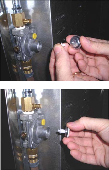
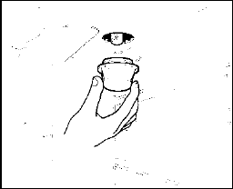
Toconverttheregulatorforusewithotherliquid
propaneLPgas:
1. Unscrewbyhandtheuppercapofthe
regulator,removethewhiteplastic
attachmentfromthecap,reverseits
directionandscrewitagainfirmlyagainstthe
cap.Thewhiteplasticattachmenthasarrows
indicatingthepositionfornaturalgas(NAT)
andLPgas(LP).
2. Screwbyhandthemetalcapintheoriginal
positionontheregulator.
16
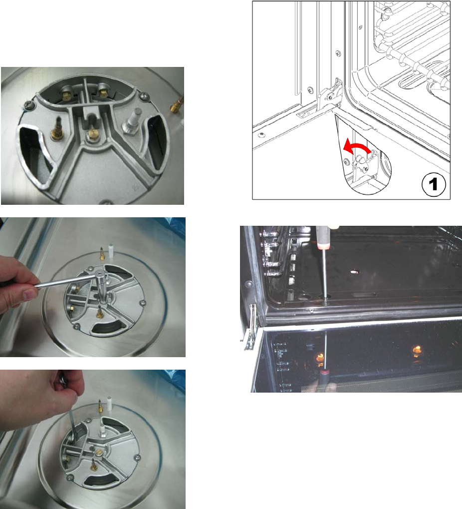
STEP2:SURFACEBURNERS
Toreplacethenozzlesofthesurfaceburners,lift
uptheburnersandunscrewthenozzlesshipped
withtherangeusinga7mm{sochetwrench).
Replacenozzlesusingtheconversionsetsupplied
withtherangeorbyaBertazzoniauthorized
partswarehouse.Eachnozzlehasanumber
indicatingitsflowdiameterprintedonthebody.
Consultthetableonpage20formatchingnozzles
toburners.
STEP3:MAINOVENBURNER
Toreplacethenozzlesofthemainovenburner,
startby:
Removetheovendoor
Toreplacethenozzlesofthemainovenburner,
startbyremovingthebottompaneloftheoven.
17
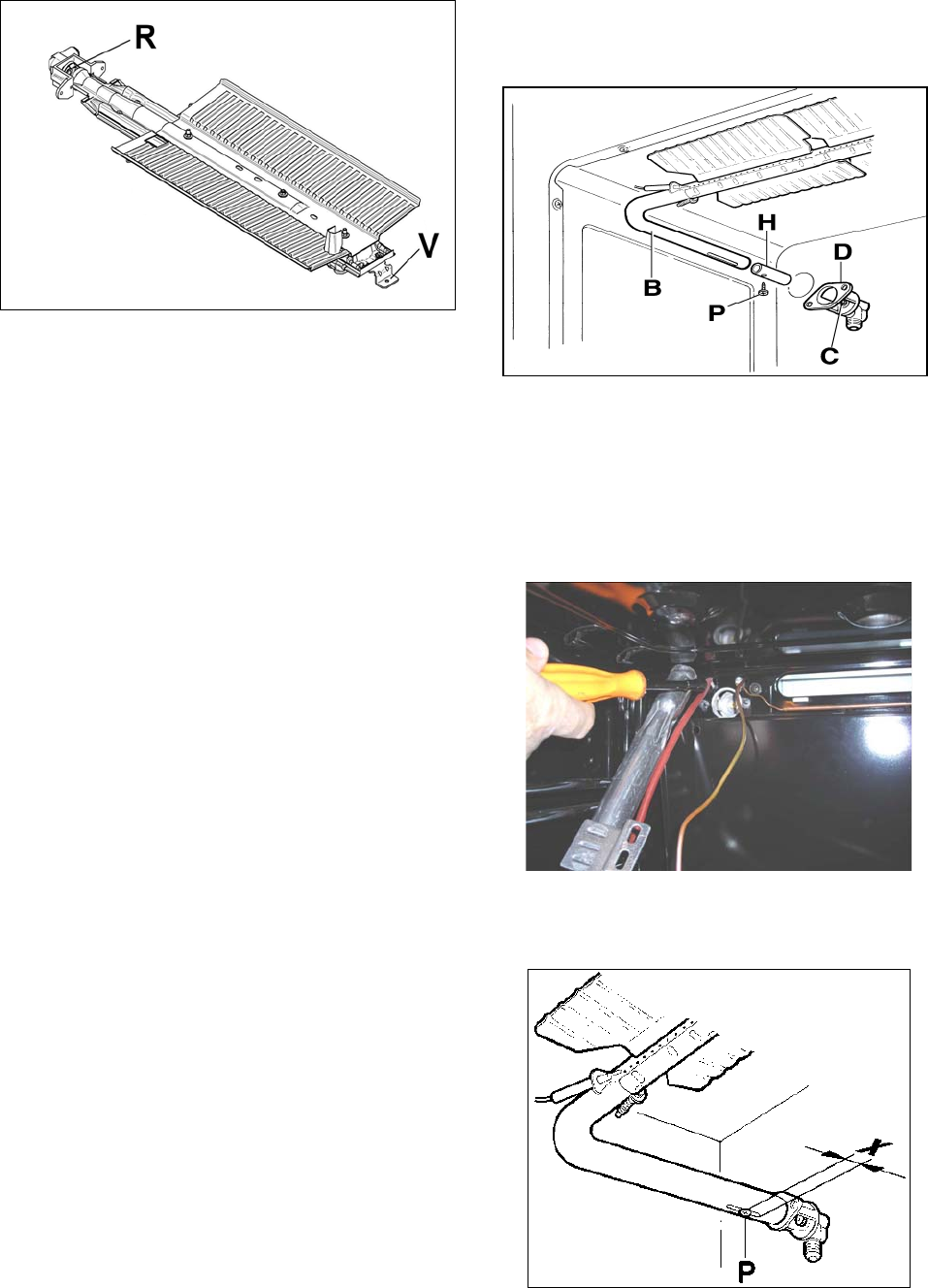
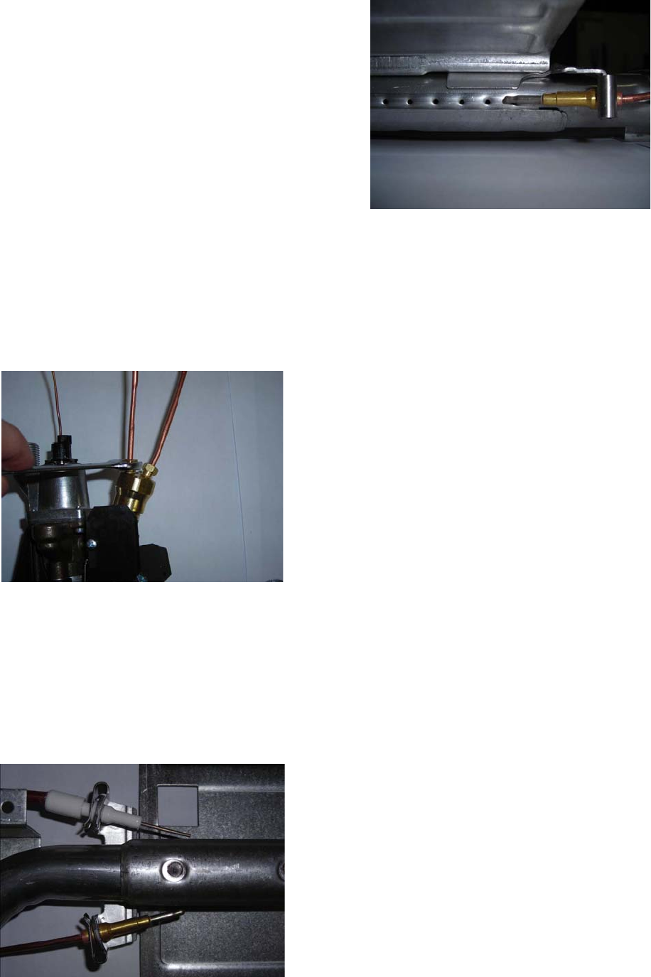
LoosenandthescrewVandpullouttheburner
fromthesupportbeingcarefulnottodamagethe
ignitionplugandthethermocouple
UnscrewthenozzleRusinga7mm.spannerand
replaceitwiththenozzleforthenewtypeofgas
accordingtowhatisindicateinthetablebelow
ATTENTION:payextraattentiontoavoiddamage
totheigniterandthermocouple.
Re‐installallthepartsinreverssequence
STEP4:BROILERBURNER
Loosenthescrewandpullouttheburnerfrom
thesupportbeingcarefulnottodamagethe
ignitionplugandthethermocouple.
Usinga7mm[nameofthetool]unscrewthe
nozzle.Replacethenozzleusingtheconversion
setsuppliedwiththerangeorbyaBertazzoni
authorizedpartswarehouse.Eachnozzlehasa
numberindicatingitsflowdiameterprintedon
thebody.Consultthetableonpage20for
matchingnozzlestoburners.
AdjustthegapXbysettingittofullyopen
position.
18
STEP5:VISUALCHECKS
Beforereinstallingthebottompanel,the
followingvisualcheckmustbeperformedto
ensurethattheconversionhasbeencarriedout
properlyandwithoutdamagetoother
componentsoftherange.
A) CONNECTIONOFTHERMOCOUPLESTO
THERMOSTAT
Thethermocouplesforbothbroilerandmain
ovenburnerareconnectedtothesamemagnet.
Tightgentlythetwoconnectionsalternating
actiononthetwonuts.Donotfullytightenone
thermocouplebeforehavingstartedtotighten
thesecondone.
B) OVENIGNITERANDTHERMOCOUPLE
POSITION
Theappropriategapbetweenthetipofthespark
plugorthermocoupleandtheburnershallbe
approximately1/8’’.
Thetipofthesparkplugorthermocouplemust
fullyoverlapatleastthefirstgasemissionholeof
theburner.
Afterperformingallthesevisualchecks,reinstall
thebottompaneloftheovencompartmentand
proceedtosettingtheminimumforeach
burner.
19
STEP6:MINIMUMFLAMEADJUSTMENT
WARNING!
Theseadjustmentsshouldbemadeonlyforuse
oftheappliancewithnaturalgas.Forusewith
liquidpropanegas,thechokescrewmustbe
fullyturnedinaclockwisedirection.
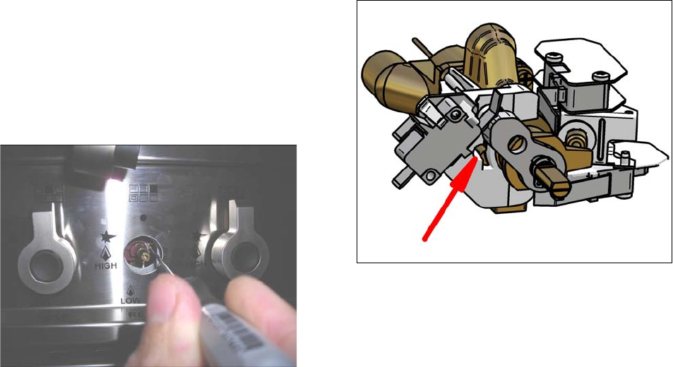
SURFACEBURNERS
1. Lightoneburneratatimeandsettheknob
totheMINIMUMposition(smallflame).
2. Removetheknob.
3. Therangeisequippedwithasafetyvalve.
Usingasmall‐sizeslottedscrewdriver,locate
thechokevalveonthevalvebodyandturn
thechokescrewtotherightorleftuntilthe
burnerflameisadjustedtodesiredminimum.
4. Makesurethattheflamedoesnotgoout
whenswitchingquicklyfromtheMAXIMUM
totheMINIMUMposition.
OVENBURNER
1. Settheoventemperaturecontrolknobtothe
MAXIMUMsetting.
2. Closetheovendoorandoperatetheovenfor
atleast10minutes.
3. SettheknobtotheMINIMUMsetting.
4. Removetheknob.
5. Withaslottedscrewdriverturnthechoking
screw(by‐passscrewattheleftsideofthe
thermostatbar)and,whileobservingthe
flameatthesametimethroughthebottom
ovenporthole,evaluatetheconsistencyof
theflamesoitremainsonwhenswitching
quicklyfromMINIMUMtoMAXIMUM
setting.
Broilerburner:thebroilerburneralways
operatesatmaximum,thereforenominimum
adjustmentisrequired.

20
Models
MAS30 4 GAS XT [M7S0GNA7X (2,5)AUA]
MAS30 4 GAS XE [M7S0GNA7X (2,5)AUG]
Burner Position Injector Gas Pressure Max Rate Min Rate By-pass
diam. [mm.] Type [i.w.c.] [BTU/h] [W] [BTU/h] [W] diam. [mm]
Auxiliary Rear L 0,92NG 4”
37501098 900 264 Regulated
0,56LP (Propane) 11” 37501098 900 264 0,29
Semi-Rapid Front R 1,17NG 4”
60001759 1500 439 Regulated
0,73LP (Propane) 11” 63001845 1500 439 0,36
Rapid Rear R 1,55NG 4”
104003046 2500 732 Regulated
0,98LP (Propane) 11” 114003339 2500 732 0,47
Front L Inner 0,80NG 4”
2730799900 264 Regulated
Dual Burner 0,50LP (Propane) 11” 2900849900 264 0,29
Front L Outer N°2x1,30NG 4”
150004394 4500 1318 Regulated
N°2x0,83LP (Propane) 11” 164004804 4500 1318 0,65
Oven Oven 1,85 NG 4” 14500 4248 3500 1025 Regulated
downside 1,10 LP (Propane) 11” 14500 4248 3500 1025 0,54
Broiler Oven 1,70 NG 4” 12000 3516 Only Max Only Max No by-pass
upside 0,98 LP (Propane) 11” 12000 3516 Only Max Only Max No by-pass
21
INSTALLATIONCHECKLlST
1. Istherangemountedonitslegs?
2. Isthebackguardsecurelyconnected?
3. Hastheanti‐tipdevicebeenproperly
installed?
4. Doestheclearancefromthesidecabinets
complywiththemanufacturersdirections?
5. Istheelectricityproperlygrounded?
6. Isthegasservicelineconnectedfollowing
thedirectionsofthemanufacturer?
7. Haveallthepropervalves,stoppersand
gasketbeeninstalledbetweentherangeand
theserviceline?
8. Hasthegasconnectionbeencheckedfor
leaks?
9. Hastherangebeensetforthetypeofgas
availableinthehousehold?
10. Istheignitionofallovenburnersfunctioning
properly?
11. Istheairflowtotheoverandbroilerburners
properlyadjusted?
12. Doestheflameappearsharpblue,withno
yellowtipping,sootingorflamelifting?
13. Hastheminimumsettingforallburnersbeen
adjusted?
14. Istheovenandbroilerignitionworking
properly?
15. Doestheovenlightworkproperly?
FINALPREPARATION
Beforeusingtheoven,removeanyprotective
wrapfromthestainlesssteel.
Allstainlesssteelbodypartsshouldbewiped
withhot,soapywaterandwithaliquidstainless
steelcleanser.
Ifbuildupoccurs,donotusesteelwool,abrasive
cloths,cleaners,orpowders!Ifitisnecessaryto
scrapestainlesssteeltoremoveencrusted
materials,soakwithhot,wetclothstoloosenthe
material,thenuseawoodornylonscraper.Do
notuseametalknife,spatula,oranyothermetal
tooltoscrapestainlesssteel!Scratchesare
almostimpossibletoremove.
Beforeusingtheovenforfoodpreparation,wash
thecavitythoroughlywithawarmsoapand
watersolutiontoremovefilmresiduesandany
dustordebrisfrominstallation,thenrinseand
wipeddry.
22
USERMANUAL
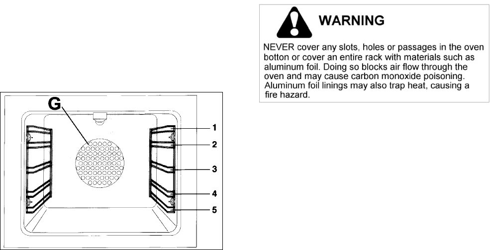
WARNING!
Donottocovertheholesinsidetheovenwith
aluminiumfoil.
Donottocovertheworktopwithaluminium
foil.
Donotstoreanyflammableobjectorobjects
underpressureinthestoragecompartment.
Keeptheareaofoperationoftherangefreefrom
combustiblematerials,gasolineandother
flammablevaporsandliquid.
Donotstoredangerousorflammablematerialsin
thecabinetsabovetheappliance.
Donotusetheapplianceforspaceheating.
Donotuseaerosolspraysinthevicinityofthe
appliancewhilecooking.
Donotsitorstepontheovendoor.
Donotuseovencompartmentforstorage.
ROOMVENTILATION
Theuseofagascookingappliancegenerates
heatandhumidityintheroomwhereitis
installed.Properventilationintheroomis
needed.Makesurethekitchenisequippedwith
arangehoodofappropriatepower(300CFM
minimum).Activatetheexhaustfan/rangehood
whenpossible.Intensiveandcontinuoususeof
theappliancemayrequireadditionalventilation,
forexamplebyopeningawindow.
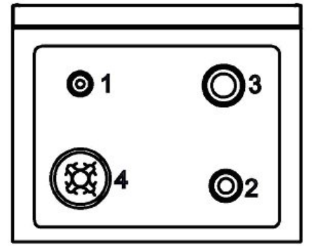
SURFACEBURNERLAYOUT
Reflectnamesfrombrochure
1.SmallBurner
2.Mediumburner
3.Rapidburner
4.Dualburner(Powerburner)
23
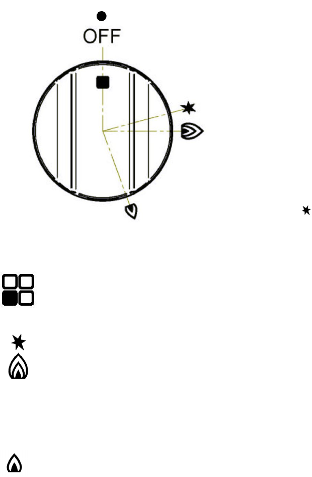
SURFACECOOKING
SYMBOLS
Burnerposition(inthiscase
frontleftburner).
Maximumtemperature
setting/Recommended
controlknobpositionfor
burnerignition
Minimumtemperaturesetting
SURFACEBURNEROPERATION
THERMOCOUPLESAFETYVALVE
EachsurfaceburnerofaBertazzonirangeis
equippedwithathermocouplesafetydevice.
Thethermocoupleopenstheflowofgastothe
burneronlywhenhot.Shouldtheflamegooff,
thethermocouplewillimmediatelyclosethegas
flowtotheburnereliminatinganyrisktoyour
home.
Forfasteractivationofthethermocouple,always
lighttheburnersonmaximumpower.Thiswill
allowthethermocoupletoreachtheoptimum
temperatureinthefastesttime.
ELECTRICIGNITION
Toactivatetheelectricignition,simplyturnthe
controlknobcounter‐clockwisetomaximum
power(( position).Presstheknobtostartthe
flowofgasandtheignitionspark.Thesparkwill
releasedatthemetaltipofthewhiteceramicpin
locatedonthesideoftheburner.Oncetheflame
ison,releasethecontrolknobgently.
Iftheflameturnsoff,repeattheabove
procedure.
Thedualpower‐burneriscomposedbytwo
burners(insideandoutside).Eachburneris
activatedbyaseparatecontrolknob.Thetwo
burnerscanbeoperatedseparatelyortogether
formaximumpower.Toactivatethepower‐
burner,turnonthecentralburnerfirst,thenturn
ontheexternalring.
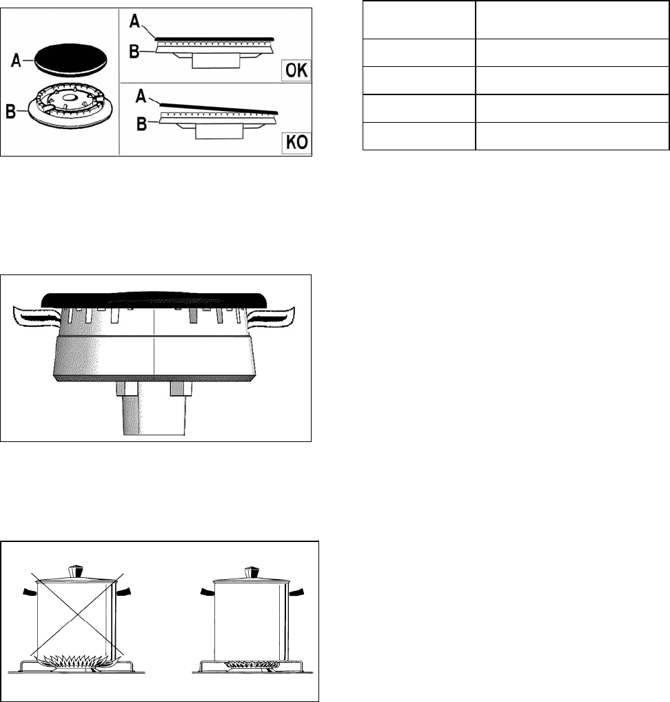
ATTENTION:donotigniteburnersiftheblack
burnercapisnotinstalledornotcentred.The
flamewillbeirregular.
MANUALIGNITION
Manualignitionisalwayspossibleevenwhenthe
poweriscutofforintheeventofpowerfailure.
Turnthecontrolknobcounter‐clockwisetothe
MAXIMUMposition.Lighttheflamewitha
kitchenlighterorwithamatch.
24
TIPSFORUSINGBURNERSCORRECTLY
WARNING!
KEEPCHILDRENATASAFEDISTANCEFROMTHE
APPLIANCEDURINGOPERATION.
DONOTALLOWCHILDRENTOOPERATETHE
APPLIANCE.
1. Alwayscheckthattheburnercapsare
properlyinstalledbeforeoperation.
2. Verifythattheflameoftheworktopburners
iscompletelyblueandwithregularaspectas
shownbelow.
3. Alwaysadjusttheburnerflamesoitdoesnot
extendbeyondtheedgeofthepan.
TIPSFORUSINGPANSCORRECTLY
ATTENTION!
Alwaysensurethatbottomandhandlesofpans
donotprotrudefromtheworktop.
Whencookingwithflammablefatsuchasoil,do
notleavetherangeunattended.
Usepotsoftheappropriatesizeoneachburner
followingtheindicationofthediagrambelow.
Whenboilingliquids,turntheknobtothe
MINIMUMpositiononceboilingisreachedto
avoidoverflow..
Alwaysusepotswithmatchinglid.
Drythebottomofpansbeforeoperation.
Usepotswithaflat,thickbottom(exceptforwok
cooking).
WOKCOOKING:alwaysusethewokadapter
suppliedwiththerange.Wokpanexternal
diametershallnotbesmallerthan10”(25cm)
andlargerthan16”(40cm).
SIMMERING:usethesimmerringsuppliedwith
therange.
BurnerRecommendedpansize
inches(mm)
Small3½”‐51/2”(90–140)
Medium51/2”‐101/4”(140–260)
Large 71/8”‐101/4”(180–260)
Dualburner 82/3”‐101/4”(220–260)
25
OVENCOOKING
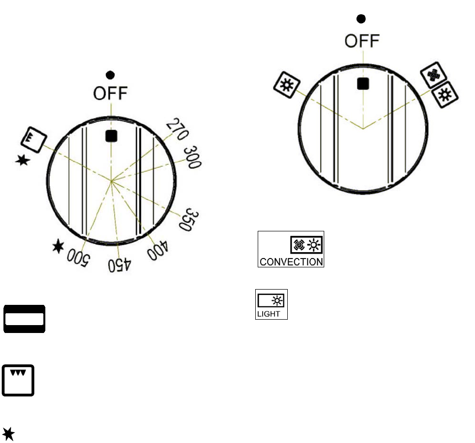
SYMBOLS
Thermalbakeselector
Broilerselector
Recommendedcontrolknob
positionforburnerignition
270F Mimimumoventemperature
setting
500FMaximumoventemperature
setting
Ovenon/offOvenstatusindicator.
Convectionfanandoven
compartmentlightswitch
Ovencompartmentlight
switchforbakingorbroiling
26
OVENSHELVES
Bertazzonirangesareequippedwithcommercial
gradeshelvesandaenamelcookingtray.
Shelvesaremountedontheappropriateguides
situatedonthesidesoftheovencompartment.
Inserttheshelfbetweentopandbottomguidein
anyofthe5positionsavailable.
Tokeeptheovenascleanaspossible,cookmeat
onthetray.
Whenavailable,alwaysfollowrecipebook
directions.Personalexperiencewillhelpto
determineanyvariationsinthevaluesreported
inthetable.Inanycase,itisrecommendedto
followtheinstructionsofthespecificrecipebeing
used.
GASOVENOPERATION
THERMOCOUPLESAFETYVALVE
Bertazzonigasovensareequippedwitha
thermocouplesafetydeviceandathermostatto
setthepropercookingtemperature.
Thethermocoupleopenstheflowofgastothe
burneronlywhenhot.Shouldtheflamegooff,
thethermocouplewillimmediatelyclosethegas
flowtotheburnereliminatinganyrisktoyour
home.
Forfasteractivationofthethermocouple,always
lighttheburnersonmaximumpower.Thiswill
allowthethermocoupletoreachtheoptimum
temperatureinthefastesttime.
ATTENTION!
Whenusingtheovenforthefirsttimeitshould
beoperatedfor15‐30minutesatatemperature
ofabout500°F/260°Cwithoutcookinganything
insideinordertoeliminateanymoistureand
odoursfromtheinternalinsulation.
27
ELECTRICIGNITION
WARNING!
Alwayskeeptheovendooropenwhenlighting
theoven.
Warning:Donotusethegasovenorbroilerin
caseofelectricpowerfailure
Opentheovendoor,turntheknobtothe
maximumtemperaturesetting,presswellthe
knobfor1sec.Andrelaseit,theautomatic
ignitionsystemwillautomaticallygeneratethe
sparkfor5secondsandwillengagethe
termocouple.Thencheckthattheovenburner
flameisandremaincorrectlylit,andclesethe
door.
Donotpresstheovenknobformorethan2,5
sec.otherwiseautomaticignitionsystemlock
itselfanditwillbenecessarytoretrythewhole
ignitionsequence;iftheovenburnerdonot
remaincorrectlylitatthefirstattempt,open
thedooroftheroomandwaitatleast60sec.
beforetoretrytoignitetheovenburner.
WARNING
Iftheovenburnerflameisextinguished
accidentallyduringoperation,turnthe
temperaturecontrolknobcounter‐clockwiseto
theoffposition.Waitatleast60secondsbefore
attemptingtolighttheovenagain.
CONVECTIONCOOKING
Bertazzonigasovenareequippedwitha
CONVECTIONfan.
Inconvectionmode,thefansituatedattheback
oftheovencompartmentcreateshorizontal
forced‐aircirculation.Theadvantagesof
convectioncookingare:
1.uniformdistributionofheatthroughoutthe
ovencavity(meatnolongerneedstobeturned
whileroasting)
2.cookingdifferenttypesoffoodatthesame
time,withoutflavourtransmissionfromonedish
totheother.
Pre‐heatingtheovenisnotnecessary.For
delicatepastrybaking,itisrecommendedtoheat
theovenbeforeinsertingthepastrytrays.
Toactivatetheconvectionfanusetheselector
placedoncontrolpanel.
28
COOKINGWITHTHEGASBROILER
WARNING
Alwayskeeptheovendooropenwhenlighting
thegasbroiler.
Thegasbroilerisactivatedwiththesamecontrol
knobusedforsettingtheoventemperature.
Toactivatethebroiler,turnthecontrolknob
clockwiseinthebroilerposition.
Thebroilerburneralwaysoperatesatmaximum
powerandthereforethereisnotemperature
setting.
ELECTRICIGNITION
Warning:Donotusethegasovenorbroilerin
caseofelectricpowerfailure
Opentheovendoor,turntheknobtothebroiler
positionsetting,presswelltheknobfor1sec.
Andrelaseit,theautomaticignitionsystemwill
automaticallygeneratethesparkfor5seconds
andwillengagethetermocouple.Thencheck
thatthebroilerburnerflameisandremain
correctlylit,andclesethedoor.
Donotpressthebroilerknobformorethan2,5
sec.otherwiseautomaticignitionsystemlock
itselfanditwillbenecessarytoretrythewhole
ignitionsequence;ifthebroilerburnerdonot
remaincorrectlylitatthefirstattempt,open
thedooroftheroomandwaitatleast60sec.
beforetoretrytoignitethebroilerburner.
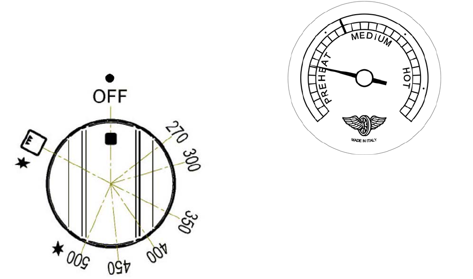
USINGTHETHERMOMETER
OnlymodelMAS304GASXT
Therangeisfittedwithadevicethatgivesa
quantitativeindicationofthetemperatureinthe
middleoftheoven.
29
MAINTAININGYOURRANGE
REPLACINGTHEOVENLIGHTBULB
WARNING!
Disconnectpowerbeforeservicingunit.
Toreplacetheovenlightbulb,unscrewthe
protectioncapthatprojectsoutinsidetheoven.
Sparebulbsareavailableatfactory‐authorized
partsresellerslistedonpage4.
Alternativelyusecommercialbulbstype[list
SPECS]
COOLINGFANFAILURE
Bertazzonirangesareequippedwithacooling
fan.Thefanstartsoperatingeachtimetheoven
knobisonapositiondifferentfrom0(zero).
Thefancirculatestheairbetweenthecontrol
panelandtheovendoor,allowingthecontrol
panelandtheovendoortoremaincoolwhile
cooking.
Malfunctionofthecoolingfanisindicatedbythe
FANFAILURElightsituatedattheleftsideofthe
controlpanel.Ifthelightison,turnoffall
burnersassoonaspossibleandcallthecustomer
servicehotlinetoscheduleservicebyafactory‐
trainedprofessional.
CLEANINGYOURRANGE
ATTENTION!
Neveruseabrasivecleaners!
Scratchesonthestainlesssteelsurfacesare
permanent.
Donotcleantherangewhenhot!
Cleaningafterinstallation:useastainlesssteel
cleaningproductorwipetoeliminatetheglue
residuesoftheblueprotectionfilmafter
removal.
Cleaningtheworktop:periodicallycleanthe
burnerheads,thecastironpansupportsandthe
burnercapsusingwarmwater.Removeburned
foodandfatresidueswitharubberspatula.If
foodresiduepreventthesmoothoperationof
thecontrolknobs,callthecustomerservce
hotlinetoscheduleservicebyafactory‐trained
professional.
Cleaningstainlesssteel:forbestresultsusea
stainlesssteelcleanerproductwithasoftsponge
orwipe.Alternativelyuseasoftspongeorcloth
withawarmsoapandwatersolution.Neveruse
abrasivepowdersorliquids!
Cleaningtheburnercaps:lifttheburnercaps
fromtheburnerheadsandwashtheminawarm
soapandwatersolution.Drythoroughlybefore
usingthemagain.Beforereinstallingthemonthe
burnerhead,checkthatthegasflowholesare
notcloggedwithfoodresiduesorcleaning
productresidues.
CleaningEnamel:enamelledpartsshouldbe
cleanedfrequentlywithawarmsoapandwater
solutionappliedwithasoftspongeorwipe.
Neveruseabrasivepowdersorliquids!Donot
leaveacidoralkalinesubstancesonthe
enamelledparts(suchasvinegar,lemonjuice,
salt,tomatosauce,etc.).Usearubberspatulato
removefatresidues.
Cleaningglassdoor:cleantheglassusinganon‐
abrasivespongeorwipewithawarmsoapand
warmwatersolution.Usearubberspatulato
removefatresidues.
Cleaningtheinsideoftheovenglass:Oven
featureistheabilitytoremovetheinnerglass.
Afteryouopenthedoorcompletelyandlockthe
hinges(fig.1)unhooktheengagementsshows
thefigure(2‐3)liftandremovetheinnerglass
(fig.4)andthencleanthecrystal.Suchan
operationistobeperformedincoldovenand
withadampcloth,takingcarenottouse
abrasives.Toreassembletheglassdothe
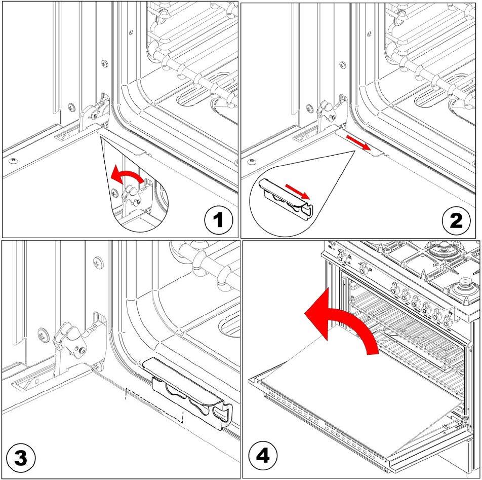
30
oppositemakingwiththesameorientationthat
hasbeendisassembled,rememberingthatthe
smoothpartbothinvistaandtheremainsinside
thescreen‐printedglassovendoor.Onceyou
havereassembledtheglassblockwiththe
engagementsandunlockinghinges.
Caution:donotloosenthehingesiftheinner
glassisnotmountedonthedoor.
Cleantheinsideoftheoven:Tofacilitate
intensivecleaningoftheoveniseasyto
disassemblethedoorbyfollowingthebelow
instructions.Afteryouopenthedoorcompletely
andlockthehinges(fig.1),putthedoorinasemi‐
openpositionandusingbothhandspullit
towardsyouuntilitisreleasedfromthe
attachment..Toreassemblethedooroperatein
reverseorder.Theyarealsoeasilyofftheside
grids,byunscrewingthenutsthatfastenthe
oven.
ATTENTION:whilecleaningthedoor,avoid
spillageoffoodresideuesandcleaningproducts
intheventingholessituatedonthetopsideof
thedoor.Tocleantheinsideoftheovendoor,
callafactory‐trainedprofessional.
ATTENTION:forfurtherdetailsaboutcleaningof
theappliance,pleasecontactyourappliance
retailer.
31
IMPORTANTAPPLIANCEINFORMATION
MODEL______________________________________________________________
DATEINSTALLED_______________________________________________________________
DEALER _______________________________________________________________
_______________________________________________________________
INSTALLER _______________________________________________________________
________________________________________________________________
SERVICER _______________________________________________________________
________________________________________________________________

32
BERTAZZONISpA
ViaPalazzina8
42016GuastallaRE
ITALY
WWW.BERTAZZONI‐ITALIA.COM
