Bewator 5PQXX500 xx500 Series Readers User Manual Proximity Readers Handbook
Bewator Ltd. xx500 Series Readers Proximity Readers Handbook
Bewator >
Proximity Readers Handbook

Proximity
Readers Handbook
HB00117 Issue 1
Applicability
This handbook applies to the PR500 Proximity Reader,
the HD500-2 Heavy Duty Proximity Reader, the SP500 Switch Plate
Proximity Reader and the PM500 Panel Mount Proximity Reader
© BEWATOR LTD JULY 2003
This handbook is based on the best information available to Bewator at the time of publication.
Although every effort is made to keep our documentation up to date, small changes which arise from
the Company's policy of continuing product improvement are not necessarily incorporated. Some
products are not available in all countries. All orders are accepted only on the Company's standard
Conditions of Sale, copies of which are available on request.
Bewator Ltd, Albany Street, Newport, South Wales, NP20 5XW, UK
Tel: +44 (0)1633 821000 Fax: +44 (0)1633 850893
Email: sales@bewator.co.uk Website: www.bewator.co.uk


NOTE: This equipment has been tested and found to comply with the
limits for a Class B digital device, pursuant to part 15 of the FCC Rules.
These limits are designed to provide reasonable protection against
harmful interference in a residential installation. This equipment
generates, uses and can radiate radio frequency energy and, if not
installed and used in accordance with the instructions, may cause
harmful interference to radio communications. However, there is no
guarantee that interference will not occur in a particular installation.
If this equipment does cause harmful interference to radio or television
reception, which can be determined by turning the equipment off and
on, the user is encouraged to try to correct the interference by one or
more of the following measures:
- Reorient or relocate the receiving antenna.
- Increase the separation between the equipment and the receiver.
- Connect the equipment into an outlet on a circuit different from
that to which the receiver is connected.
- Consult the dealer or an experienced radio/TV technician for help.

Safety
This equipment must be powered by a supply which is suitably insulated
from the mains. The supply should be classed as SELV under the terms
of EN60950.
The power supply must be connected to safety earth. A mains isolation
switch should be provided by the installer. Any third party equipment
connected must also be suitably insulated from the mains supply.
Any fuses which are replaced must be of the recommended rating and
type.
Wiring connected by the installer must be adequate. The use of
inadequate wiring may present a fire hazard.
Except where specified the equipment is not suitable for outside use.
Except where specified this equipment is not for use in safety critical
applications.

i
Contents
Chapter 1 Introduction
Reader types............................................................................................1-1
Data output.............................................................................................1-1
Interrogation of cards and tags.................................................................1-2
Setting up the Reader...............................................................................1-2
Chapter 2 Installing and connecting
PR500-2 Proximity Reader........................................................................2-1
HD500-2 Heavy Duty Proximity Reader.....................................................2-3
SP500 Switch Plate Proximity Reader........................................................2-6
PM500 Panel Mount Proximity Reader ......................................................2-8
Configuring and testing the Reader...............................................2-10
Chapter 3 Setting up
Configuring the Reader.............................................................................3-1
The configuration card .............................................................................3-1
The DC/SC card ......................................................................................3-2
Programming the configuration card.........................................................3-2
0xxs (secondary code swap) 3-2
xbff (ASCII interface protocol and baud rate).....................................3-3
xxxh (Data Hold input signal polarity)................................................3-3
xxhe (horn configuration) 3-4
hhhh (hold-off time) ........................................................................3-4
pxxx (calculation of leading parity bit for 26-bit Wiegand interfaces)....3-5
xxrg (internal/external control ofred and green LEDs)........................3-5
crrrrrrr (Secondary Code check disable,
and repeat data delay - RDD) .....................................................3-6
iiiiiiii (interface number) 3-6
Note to existing users of PR500 and HD500 ....................................3-6
Programming the DC/SC card..................................................................3-7
Presenting configuration card and DC/SC card to the Reader....................3-7
Changing the Secondary Code or Distributor Code....................................3-7
Examples of working out what to program into the
configuration card in 63-bit mode on the Programmer...............................3-8
Example 1.........................................................................................3-8
Example 2.........................................................................................3-9

Proximity Readers Handbook
ii
Chapter 4 Data interfaces
Electrical characteristics of outputs from the Reader.................................4-1
Data Hold input.......................................................................................4-2
Wiegand ..................................................................................................4-2
Connections......................................................................................4-2
Electrical characteristics....................................................................4-2
Data format.......................................................................................4-3
Card data ......................................................................................4-3
Interface settings...............................................................................4-4
Magnetic Stripe........................................................................................4-5
Connections......................................................................................4-5
Electrical characteristics....................................................................4-5
ASCII data output - TTL voltage levels.......................................................4-7
Connections......................................................................................4-7
Electrical characteristics....................................................................4-7
Data format.......................................................................................4-8
Protocol ............................................................................................4-8
4101/4010 Controller interface..........................................................4-8
Chapter 5 Operation
LEDs.......................................................................................................5-1
Card interrogation....................................................................................5-1
Standard interrogation routine...........................................................5-1
Using cards .............................................................................................5-2
Looking after a card...........................................................................5-2

1-1
Chapter 1
Introduction
The PR500, HD500-2, SP500 and PM500 Proximity Readers are
designed to read the codes contained in Cotag coded cards and tags
and to pass these codes, if valid, to a host system. These Readers are
primarily for use by OEMs to provide proximity reading for their own
proprietary access control systems.
Each Reader requires a power supply, but can usually share the
same supply as the door lock.
Reader types
The PR500 Proximity Reader is a general purpose proximity reader
which is small and slim and can be mounted on a wall or door frame.
The HD500-2 Heavy Duty Proximity Reader has a stainless steel
frame, held in place by four tamper-resistant screws, which covers
the mounting screws. This makes it suitable for applications where
vandalism could be a problem.
The SP500 Switch Plate Proximity Reader fits a standard single
surface-mount or flush fitting back box, either metal or plastic, such
as is used for light switches and mains plug sockets2-hole mounting
for screwing it to a standard single-way back box.
The PM500 Panel Mount Proximity Reader can be mounted within a
sheet metal or plastic panel using four screws.
Data output
The Readers provide Wiegand or Magnetic Stripe format data output,
or ASCII data output at TTL voltage levels (0V and +5V). (The Readers
are available in AB format if you require BCLINK data output, but
this option is not described in this handbook.)
For some OEM systems, the data lines from two Readers can be
connected in parallel, the host polling each Reader in turn using the
Data Hold input. When this input is held low, the Reader buffers the
data from one transaction. The host must release the Data Hold line
and read the message before the next card is read, or else the
message is discarded by the Reader.

Proximity Readers Handbook
1-2
Interrogation of cards and tags
The Reader uses “standard interrogation” which reads the card code
just once and outputs the data in a little under half a second for
standard cards and tags, or in one tenth of a second for fast cards
and tags. If there is too much electrical noise to read a card or tag,
the amber LED indicator on the unit flashes.
The interrogation routine checks both the Distributor Code and the
Secondary Code* of a card or tag and sends data to the host system
only if both are valid.
*Note that the Secondary Code check can be disabled with some
interfaces - see chapter 3 for details.
Setting up the Reader
You configure the Reader by presenting it with two coded cards. The
first card (the configuration card) defines the type of data interface,
and various other features*. The second card (any of the ordinary
Distributor Coded cards which will be used with the system) teaches
the Reader its Distributor and Secondary Codes. Note that you
cannot teach the Reader its Distributor and Secondary Codes without
first presenting the configuration card.
When the Reader is powered up, it waits 4 seconds for a
configuration card to be presented. If it doesn’t read a configuration
card in this time, it enters the configured operating mode.
*All the features which can be set using the configuration card are
listed on the first page of chapter 3. It is most important that you
read and understand chapter 3 of this handbook before you
attempt to install a Reader.
2-1
Chapter 2
Installing and connecting
PR500 Proximity Reader
The Reader is supplied with the cover separate. If the cover has been
fitted for any reason, remove it by pushing in the lug on its lower
edge using a suitable screwdriver.
1. Choose a suitable position to mount the Reader near the door.
The Reader has a maximum range of 30cm (12in) so it must be
mounted in a position where the card or tag can easily be
brought within this distance. We recommend it is mounted
approximately one metre (3.5ft) above the ground. Also
consider ease of access to the door once the card or tag has
been read, for example, it is better to mount the Reader near
the opening side of the door rather than the hinge side.
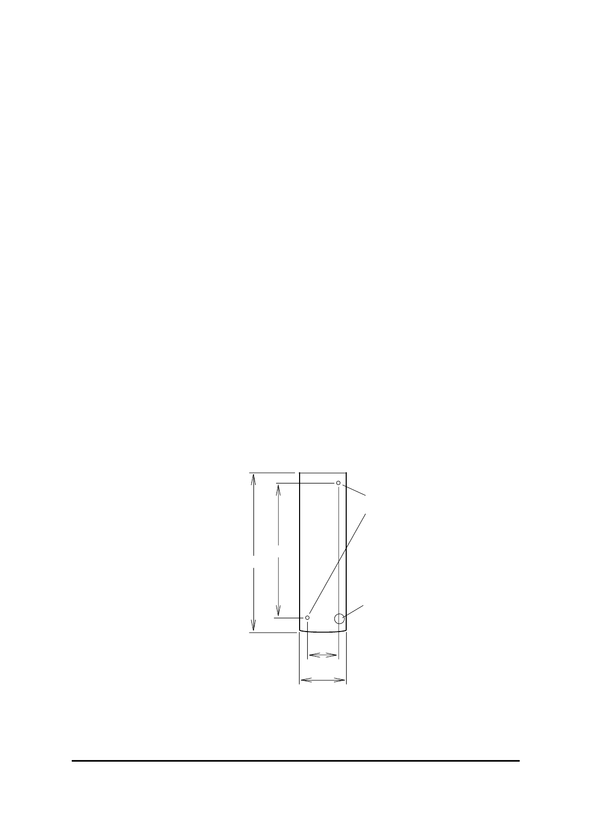
2. The Reader should be mounted with the LEDs at the top left.
Mark out and drill the two mounting holes. Don’t fix the
Reader to the wall yet. The holes accept 4mm machine screws
or No 8 wood screws.
20
37.5
118
137.5
Fixing holes:
4.2 diameter
Fixing Dimensions (mm)
Cable entry hole
9mm diameter
The cover overlaps the base slightly on all sides so you must
allow a little extra room all round.

Proximity Readers Handbook
2-2
3. Route the cables into the Reader: you can use either the cut-
out in the base or the one in the lower edge at the bottom of
the Reader.
The connections required for the Reader are power supply
connections (0V and +12V DC or +24V DC), data output
connections for Wiegand or Magnetic Stripe (D0, D1, DA) or
ASCII/TTL (H , D0, DA), and a connection from the host to the
Data Hold input (H ) if data lines from two Readers are to be
connected in parallel.
To promote EMC compliance we recommend you use 812
Cable as described here. Trim back and insulate the screens at
the PR500. Connect the screens at the host only: do not
connect the screens to the PR500.
4. When you have routed the cables into the Reader you can
screw it to the wall.
5. Make the connections shown in the following table:
Reader Function
V+ Power supply +12V unregulated or 24V battery-backed*
(absolute max 32V, min 10.6V, 100mA max)
0V Power supply 0V (-ve)
(also ground reference for data output)
H (C) “Data Hold” for Wiegand and Mag Stripe
“CTS” for ASCII/TTL
D0 (D) “Data Zero” for Wiegand
“Data” for Mag Stripe
“TXD” for ASCII/TTL
D1 “Data One” for Wiegand
“Strobe” for Mag Stripe
DA “Data Available” for Wiegand
“Present” for Mag Stripe
“RTS” for ASCII/TTL
Horn (Adr) Horn - 0V to sound, +5V to turn off
R Red LED control - 0V for red LED
R/G Single wire LED control
0V for green LED, +5V for red LED
*The PR500 is designed to be operated by 12V unregulated power supplies, or 24V
battery-backed power supplies. Operating voltage range is 10.6 to 32.0V. The upper
voltage is intended to be compatible with the charging of 24V lead-acid batteries.
Charge methods vary, and may be temperature dependent. 32V max is intended to
be compatible with commonly used charging methods. If the upper operating
voltage is exceeded then permanent damage may be caused. Installers and systems
designers should check the max power supply voltage under all conditions. Do not
operate the PR500 using unregulated 24V supplies. The PR500 current consumption
can be significantly less than 100mA. The unloaded peak voltage from a nominal
24V unregulated supply will exceed the absolute max.
6. Do not fit the front cover to the Reader until you have
configured it and tested it (see the end of this chapter).

Installing and connecting
2-3
HD500-2 Heavy Duty Proximity Reader
1. Choose a suitable position to mount the Reader near the door.
The Reader has a maximum range of 25cm (10in) so it must be
mounted in a position where the card or tag can easily be
brought within this distance. We recommend it is mounted
approximately one metre (3.5ft) above the ground. Also
consider ease of access to the door once the card or tag has
been read, for example, it is better to mount the Reader near
the opening side of the door rather than the hinge side.
2. You can mount the Reader using any of the six mounting holes
in the black plastic enclosure - the diagram at the end of this
section shows the fixing dimensions and is drawn actual size
so you can use it as a template when drilling the holes.
The Reader should be mounted with the strip of LEDs at the
top left.
Note that you do not need the stainless steel frame when
mounting the Reader - you fasten it to the Reader afterwards
to prevent anyone undoing the mounting screws.
3. Mark out and drill the mounting holes, but don’t fix the
Reader to the wall yet.
The holes accept 4mm machine screws or No 8 wood screws.
4. The connections required for the Reader are power supply
connections (0V and +12V DC or +24V DC), data output
connections for Wiegand or Magnetic Stripe (D0, D1, DA) or
ASCII/TTL (H, D0, DA), and a connection from the host to the
Data Hold input (H) if data lines from two Readers are to be
connected in parallel.
To promote EMC compliance we recommend you use 812
Cable as described here. Trim back and insulate the screens at
the HD500-2. Connect the screens at the host only: do not
connect any of the screens to the HD500-2.

Proximity Readers Handbook
2-4
Route the cables into the Reader from behind, then make the
connections shown in the table below.
Reader Function
V+ Power supply +12V unregulated or 24V battery-backed*
(absolute max 32V, min 10.6V, 100mA max)
0V Power supply 0V (-ve)
(also ground reference for data output)
H (C) “Data Hold” for Wiegand and Mag Stripe
“CTS” for ASCII/TTL
D0 (D) “Data Zero” for Wiegand
“Data” for Mag Stripe
“TXD” for ASCII/TTL
D1 “Data One” for Wiegand
“Strobe” for Mag Stripe
DA “Data Available” for Wiegand
“Present” for Mag Stripe
“RTS” for ASCII/TTL
Horn (Adr) Horn - 0V to sound, +5V to turn off
R Red LED control - 0V for red LED
R/G Single wire LED control - 0V for green LED, +5V for red LED
TAMPER Tamper circuit connection (hard wired link)#
*The HD500-2 is designed to be operated by 12V unregulated power supplies, or
24V battery-backed power supplies. Operating voltage range is 10.6 to 32.0V. The
upper voltage is intended to be compatible with the charging of 24V lead-acid
batteries. Charge methods vary, and may be temperature dependent. 32V max is
intended to be compatible with commonly used charging methods. If the upper
operating voltage is exceeded then permanent damage may be caused. Installers
and systems designers should check the max power supply voltage under all
conditions. Do not operate the HD500-2 using unregulated 24V supplies. The
HD500-2 current consumption can be significantly less than 100mA. The unloaded
peak voltage from a nominal 24V unregulated supply will exceed the absolute max.
#Two terminals are provided for use with a system 24hour tamper protection circuit.
These terminals are hard wired together on the Reader’s circuit board. If you connect
cables to these terminals, an open circuit will indicate that the wires have been cut.
5. Route the cable neatly then fix the Reader to the wall or door
frame.
6. Do not fit the stainless steel frame to the Reader until you
have configured it and tested it (see the end of this chapter).
7. When you have configured the Reader and tested it to make
sure that it is working correctly, you can fasten the Reader’s
stainless steel frame using the four “Resistorx” M4x12 screws
provided. These tamper-resistant screws can only be inserted
or removed using the correct tool which is not supplied with
Installing and connecting
2-5
the Reader: it can be obtained from Bewator Ltd as part
number TX-20H.
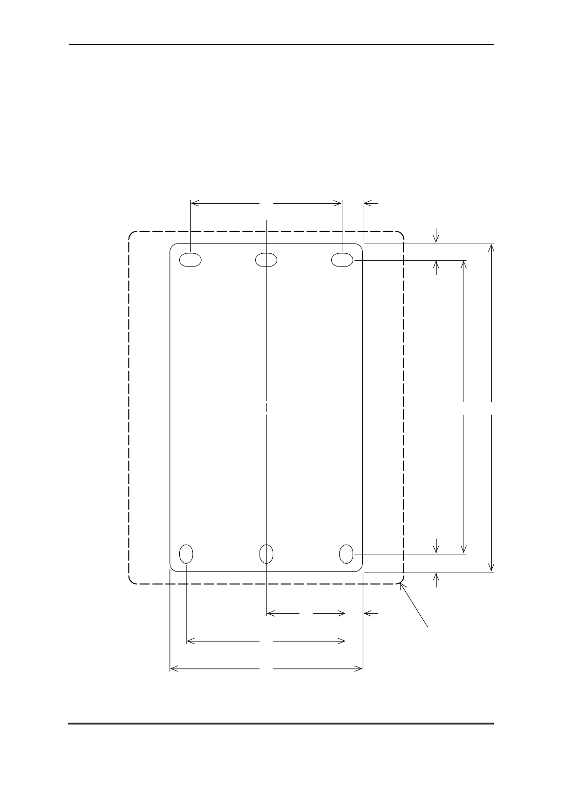
Mount the HD500-2 Reader in a suitable position near the door
approximately 1m from the floor with the LEDs at the top left. You
can fasten the Reader’s plastic case to the wall or door frame using
any of the six mounting holes provided, as shown in the diagram
below:
Fixing Dimensions (mm)
6.5
106.5 119
6
629
58
70
Stainless steel frame:
100x128
7.555

Proximity Readers Handbook
2-6
SP500 Switch Plate Proximity Reader
1. The SP500 Reader fits a standard single surface-mount or
flush fitting back box, either metal or plastic, such as is used
for light switches and mains plug sockets.
The Reader has a maximum range of 30cm (12in) so it must be
mounted in a position where the card or tag can easily be
brought within this distance.
2. The connections required for the Reader are power supply
connections (0V and +12V DC or +24V DC), data output
connections for Wiegand or Magnetic Stripe (D0, D1, DA) or
ASCII/TTL (H, D0, DA), and a connection from the host to the
Data Hold input (H) if data lines from two Readers are to be
connected in parallel.
To promote EMC compliance we recommend you use 812
Cable as described here. If the Reader is mounted in a plastic
back box then connect the screens at the host end only; at the
SP500 the screens must be cut back and insulated. If the
Reader is mounted in a metal back box then the overall screen
must be connected at the host end and also to the metal back
box. Do not connect any of the screens to the SP500 itself in
either of these situations.
Route the cables into the back box, then make the connections
shown in the table below.
Reader Function
V+ Power supply +12V unregulated or 24V battery-backed*
(absolute max 32V, min 10.6V, 100mA max)
0V Power supply 0V (-ve)
(also ground reference for data output)
H (C) “Data Hold” for Wiegand and Mag Stripe
“CTS” for ASCII/TTL
D0 (D) “Data Zero” for Wiegand
“Data” for Mag Stripe
“TXD” for ASCII/TTL
D1 “Data One” for Wiegand
“Strobe” for Mag Stripe
DA “Data Available” for Wiegand
“Present” for Mag Stripe
“RTS” for ASCII/TTL
Horn (Adr) Horn - 0V to sound, +5V to turn off
R Red LED control - 0V for red LED
R/G Single wire LED control - 0V for green LED, +5V for red LED
TAMPER Tamper circuit connection (hard wired link)#
Installing and connecting
2-7
*The SP500 is designed to be operated by 12V unregulated power supplies, or 24V
battery-backed power supplies. Operating voltage range is 10.6 to 32.0V. The upper
voltage is intended to be compatible with the charging of 24V lead-acid batteries.
Charge methods vary, and may be temperature dependent. 32V max is intended to
be compatible with commonly used charging methods. If the upper operating
voltage is exceeded then permanent damage may be caused. Installers and systems
designers should check the max power supply voltage under all conditions. Do not
operate the SP500 using unregulated 24V supplies. The SP500 current consumption
can be significantly less than 100mA. The unloaded peak voltage from a nominal
24V unregulated supply will exceed the absolute max.
#Two terminals are provided for use with a system 24hour tamper protection circuit.
These terminals are hard wired together on the Reader’s circuit board. If you connect
cables to these terminals, an open circuit will indicate that the wires have been cut.
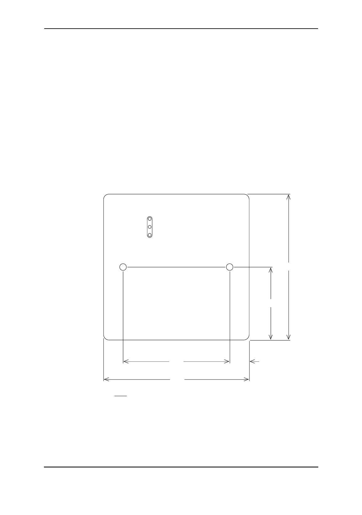
3. Screw the Reader to the back box using the two M4 screws
provided.
Fixing Dimensions (mm)
11.160.3
82.5
82.5
41.25
4. Do not clip the plastic lid on the front of the Reader until
you have configured it and tested it (see the end of this
chapter).
5. When you have configured the Reader and tested it to make
sure that it is working correctly, press the plastic cover onto
the front until it clips into place. Make sure you get the cover
the correct way round so that the LEDs can shine through the
translucent panel.

Proximity Readers Handbook
2-8
PM500 Panel Mount Proximity Reader
1. The PM500 Reader can be mounted within a sheet metal or
plastic panel using four screws. If the panel is made of metal,
the Reader must be mounted behind a 40mm square cut-out
in the panel which must be positioned in the centre of the four
mounting holes as shown in the diagram overleaf.
When mounted in a metal panel, the Reader has a maximum
range of 15cm (6in) so it must be mounted in a position where
the card or tag can easily be brought within this distance.
2. The connections required for the Reader are power supply
connections (0V and +12V DC or +24V DC), data output
connections for Wiegand or Magnetic Stripe (D0, D1, DA) or
ASCII/TTL (H, D0, DA), and a connection from the host to the
Data Hold input (H) if data lines from two Readers are to be
connected in parallel.
To promote EMC compliance we recommend you use 812
Cable as described here. If the Reader is mounted in a plastic
panel then connect the screens at the host end only; at the
PM500 the screens must be cut back and insulated. If the
Reader is mounted in a metal panel then the overall screen
must be connected at the host end and also to the metal panel.
Do not connect any of the screens to the PM500 itself in either
of these situations.
Route the cables into the panel, then make the connections
shown in the table below.
Reader Function
V+ Power supply +12V unregulated or 24V battery-backed*
(absolute max 32V, min 10.6V, 100mA max)
0V Power supply 0V (-ve)
(also ground reference for data output)
H (C) “Data Hold” for Wiegand and Mag Stripe
“CTS” for ASCII/TTL
D0 (D) “Data Zero” for Wiegand
“Data” for Mag Stripe
“TXD” for ASCII/TTL
D1 “Data One” for Wiegand
“Strobe” for Mag Stripe
DA “Data Available” for Wiegand
“Present” for Mag Stripe
“RTS” for ASCII/TTL
Horn (Adr) Horn - 0V to sound, +5V to turn off
R Red LED control - 0V for red LED
R/G Single wire LED control - 0V for green LED, +5V for red LED
TAMPER Tamper circuit connection (hard wired link)#
Installing and connecting
2-9
*The PM500 is designed to be operated by 12V unregulated power supplies, or 24V
battery-backed power supplies. Operating voltage range is 10.6 to 32.0V. The upper
voltage is intended to be compatible with the charging of 24V lead-acid batteries.
Charge methods vary, and may be temperature dependent. 32V max is intended to
be compatible with commonly used charging methods. If the upper operating
voltage is exceeded then permanent damage may be caused. Installers and systems
designers should check the max power supply voltage under all conditions. Do not
operate the PM500 using unregulated 24V supplies. The PM500 current
consumption can be significantly less than 100mA. The unloaded peak voltage from
a nominal 24V unregulated supply will exceed the absolute max.
#Two terminals are provided for use with a system 24hour tamper protection circuit.
These terminals are hard wired together on the Reader’s circuit board. If you connect
cables to these terminals, an open circuit will indicate that the wires have been cut.
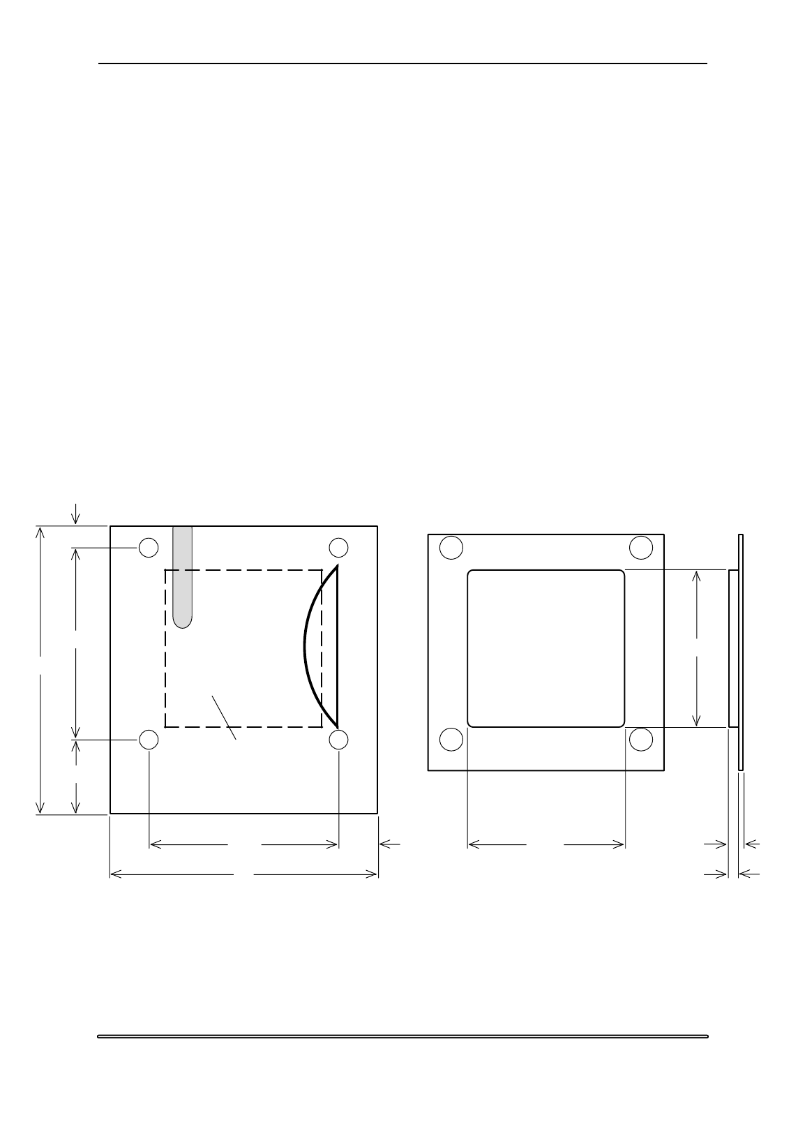
3. Mount the Reader on the panel using four M4 nuts and bolts
or self-tapping screws.
If you wish you may fit the transparent window Part Number
D01542 which gives a flush finish to the panel across the
40mm square cut-out.
Fixing Dimensions (mm)
The 40x40mm area
within this dotted
rectangle must be kept
clear of all metal
73
5.5
19
48.5
9.7548.5
68
PM500 Reader D01542 Window
4
2.5
39.8
39.8
4. Configure the Reader and test it (see next section).

Proximity Readers Handbook
2-10
Configuring and testing the Reader
1. If the Reader has already been configured by your supplier,
you can power it up and test it, see step 3 below.
2. If you need to configure the Reader yourself, power it up and
present the configuration card to the Reader within 4 seconds
of power up. During this 4 second period, the green LED is lit.
The Reader bleeps when it has read the configuration card and
the amber LED lights for a short period. After reading the
configuration card, the Reader gives you a further 8 seconds to
present one of the normal programmed cards which will be
used with the system. Doing this teaches the Reader its
Distributor and Secondary Codes. (If you do not present a
DC/SC card to the Reader within the 8 seconds, the Reader
enters its normal operating mode.)
The Reader bleeps when it has read the DC/SC card and the
amber LED lights for a short period. After the newly configured
hold-off time has elapsed, the Reader enters its normal
operating mode.
3. After configuring the Reader, test it by presenting a valid card.
The Reader’s LEDs should change from red to green (if the
LEDs are under internal control), the horn should bleep, and
the host should receive the data output.
4. If the Reader is working, you can complete the installation:
Clip the front cover in place on the PR500 and SP500 Readers.
Fit the stainless steel frame on the HD500-2 Reader using the
four “Resistorx” M4x12 screws provided. These tamper-
resistant screws can only be inserted or removed using the
correct tool which is not supplied with the Reader: it can be
obtained from Bewator Ltd as part number TX-20H.

3-1
Chapter 3
Setting up
You must set the following functions on a Reader before it will
operate correctly:
• Distributor Code
• Secondary Code
You will probably need to set the following:
• Data interface option
You may need to set the following:
• Horn operation
• Internal/external/single-wire control of LEDs
• Hold-off time and repeat data delay
• Leading parity calculation for Wiegand data output
• Position of Secondary Code in data output
• Secondary Code check disable
• ASCII interface protocol and baud rate
• Data Hold input signal polarity
Configuring the Reader
You configure the Reader by presenting it with two coded cards. The
first card (the configuration card) defines the type of data interface,
and all the features listed in the third group above. The second card
(any of the ordinary Distributor Coded cards which will be used with
the system) teaches the Reader its Distributor and Secondary Codes.
Note that you cannot teach the Reader its Distributor and Secondary
Codes without first presenting the configuration card.
When the Reader is powered up, it waits 4 seconds for a
configuration card to be presented. If it doesn’t read a configuration
card in this time, it enters its configured operating mode.
The configuration card
If you need to change the data interface or any of the other settings,
you need to use a configuration card programmed in 63 bit display
format on the 633-2 Programmer. Data fields in the configuration
card set up various options described below.

Proximity Readers Handbook
3-2
The configuration code is a 64-bit binary number which determines
how the Reader operates. Here is the complete 64-bit configuration
code, with each bit represented by a letter or number. The fields in
the code represented by the letters and numbers are defined in the
next section “Programming the configuration card”.
0xxs xxxx xxxx xxxx xxxx xbff xxxx xxxh xxhe hhhh pxxx xxrg crrr rrrr iiii iiii
The code is written down as sixteen 4-bit groups. Each 4-bit group
can be represented by a single hexadecimal digit which can be typed
directly into the 633-2 Programmer in 63-bit display format.
An x means that this bit of the code is not used.
(BCLINK users please note that “type” bits are not shown here.)
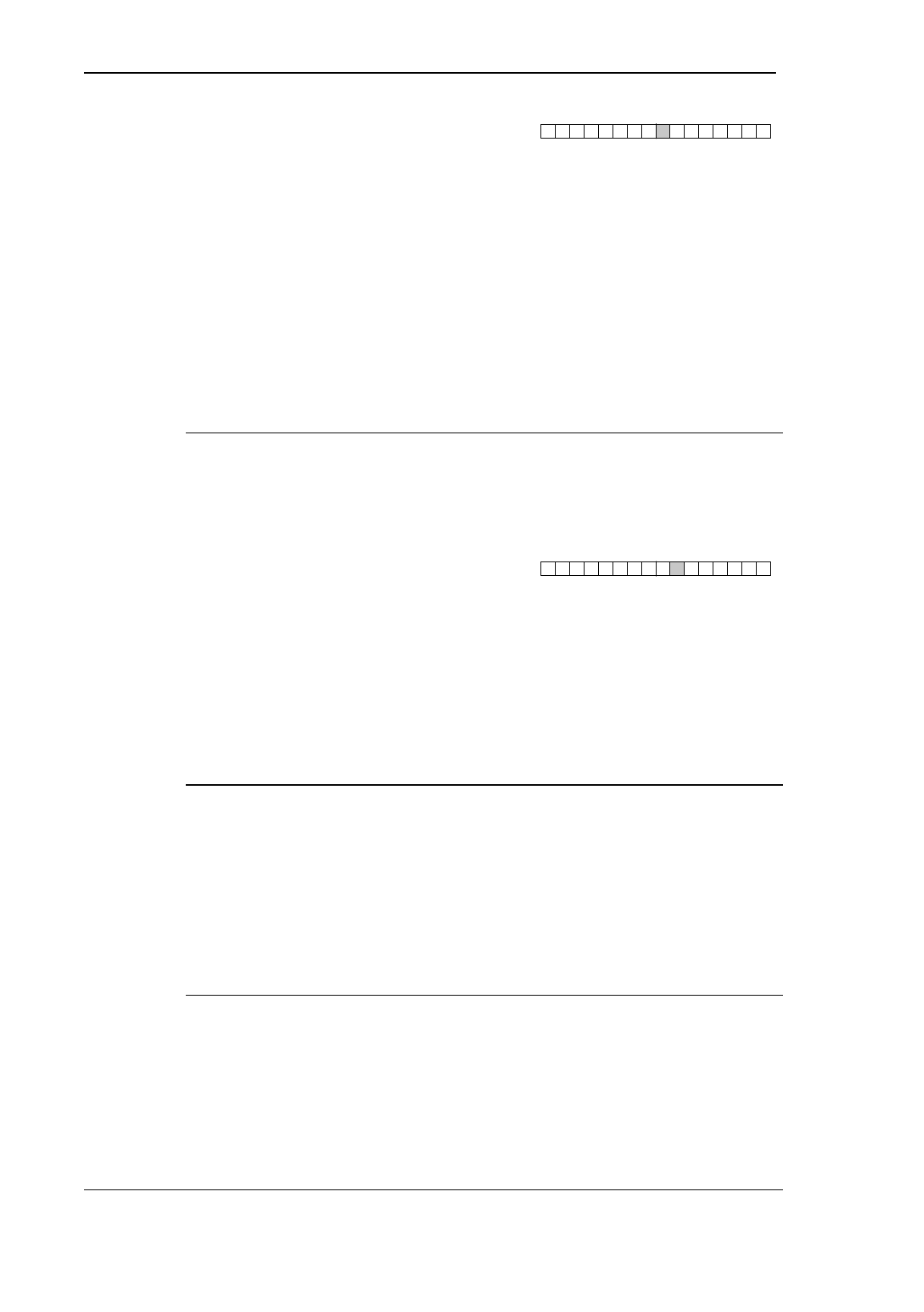
The next section “Programming the configuration card” defines each
of the fields in the configuration code. You should type each field into
the 633-2 Programmer in the order in which they are described. We
have shown a diagram with each entry, showing the position of the
hex character in the configuration code. For example, the hex
character determining the horn configuration is the ninth character:
00 000
9
Because the second to the fifth and the seventh characters are
unused, they are set to zero, and we have shown this in the diagram.
(Existing users please note that the new PR500 and HD500-2 may
require a slightly different configuration from the old PR500, HD500
and 5291 Readers.)
The DC/SC card
To teach the Reader its Distributor and Secondary Codes you use any
of the normal cards which will be used with the system (any of the
cards which are issued to cardholders). We shall call this the “DC/SC
card”.
Programming the configuration card
0xxs (secondary code swap)
00 000
1
The s bit determines whether the secondary code is output from the
Reader’s data interface as bits 33 to 48 (the position which it
occupies in the code which is programmed into the cards and tags),
or whether its position in the data output is swapped to bits 17 to 32.

Setting up
3-3
This feature is available so that cards programmed in the DEC/DEC
display format on the 633-2 Programmer can output secondary code
data using the 32-bit Wiegand or 26-bit Wiegand data interfaces
(interface numbers 02 and 12 hex respectively). This feature is invalid
for interfaces 47, 4D, 4E, 4F, 59, BC, BD and BE.
Secondary code swap bit (s):
0 the secondary code is output in its normal position (bits 33 to
48).
1 the secondary code is output in the swapped position (bits 17
to 32).
xbff (ASCII interface protocol and
00 000
6
baud rate)
The 3 bits bff determine the protocol and baud rate of the ASCII/TTL
interface. To work out the hex number you need to type into the
Programmer, refer to the following table:
Hex number ASCII protocol and baud rate
0 7 data bits, even parity, 1 stop bit, 1200 baud
1 7 data bits, odd parity, 1 stop bit, 1200 baud
2 7 data bits, no parity, 1 stop bit, 1200 baud
3 8 data bits, no parity, 1 stop bit, 1200 baud
4 7 data bits, even parity, 1 stop bit, 9600 baud
5 7 data bits, odd parity, 1 stop bit, 9600 baud
6 7 data bits, no parity, 1 stop bit, 9600 baud
7 8 data bits, no parity, 1 stop bit, 9600 baud
xxxh (Data Hold input signal polarity)
00 000
8
The h bit determines the polarity (active-low or active-high) of the
Data Hold input.
Note: if you are using the ASCII data output you must set Data Hold
to be active-high - the h bit must be set to 1.
To work out the hex number you need to type into the Programmer,
refer to the following table:
Hex number Data Hold polarity
0 Active-low
1 Active-high
Proximity Readers Handbook
3-4
xxhe (horn configuration)
00 000
9
The h bit determines whether the horn bleeps for 100ms when the
Reader reads a valid card.
The e bit determines how the horn operates when it is controlled
externally by the host. If this bit is 0, the horn sounds when the host
pulls the horn input down to 0V and continues sounding until the
host lets the horn input float high again. If this bit is 1, the horn
sounds for 1 second when the host pulls the horn input down to 0V
and then switches off automatically, irrespective of the state of the
horn input. (Note that while the horn is operating there may be some
loss of range, and the amber LED may flash.)
Hex number Internal control External control
0 100ms bleep follows horn input
1 100ms bleep sounds for 1 second
2 no bleep follows horn input
3 no bleep sounds for 1 second
hhhh (hold-off time)
00 000
10
When the Reader reads a valid card, it does not poll again until the
hold-off time has elapsed. During the hold-off time the Reader
maintains the state of the LED indicator (if the LEDs are under
internal control).
To work out the hex number you need to type into the Programmer,
refer to the following table:
Hex number Hold-off time
0 1s
1 1s
2 2s
3 3s
4 4s
5 5s
6 6s
7 8s
8 10s
Hex number Hold-off time
9 15s
A 20s
B 30s
C 40s
D 50s
E 60s
F do not use - for test purposes only

Setting up
3-5
pxxx (calculation of leading parity bit
00 000
11
for 26-bit Wiegand interfaces)
Leading parity bit (p):
0 the Reader does not calculate a leading parity bit.
8 the Reader calculates an even leading parity bit based on the
first 13 bits of the 26-bit Wiegand interface (interface number
12). This saves you from having to program the leading parity
bit into the cards. The trailing odd parity bit is still calculated
as normal.
xxrg (internal/external control of
00 00
12
0
red and green LEDs)
To work out the hex number you need to type into the Programmer,
refer to the following table:
Hex number Red LED Green LED
0 External External
1 Internal Internal
2 Internal External
Use the 0 setting when the drives for the red and green LED
indications are supplied by the host system. When you drive the
LEDs externally, you have to pull down the corresponding connection
from +5V to 0V. The R/G connection lights the green LED and the R
connection lights the red LED.
Use the 1 setting if you want the Reader alone to control the LEDs.
The red LED is lit when no card or tag is in range. The green LED
lights after a valid card read and stays on until the card is removed
from the reading area of the Reader, or the hold off time expires,
whichever is longer. The amber LED flashes if there is electrical noise
in the reading area which may affect reading of cards and tags.
The 2 setting requires external control of the green LED from the
host, but the Reader controls red and amber LEDs. This provides
single-wire control of the LED indication from the host. It works as
follows:
• The red LED is lit when no card or tag is in range.
• When the Reader reads a card or tag, the host processes the
data from the Reader, unlocks the door and lights the green
LED by pulling the R/G connection down to 0V. This also
turns the red LED off.
• When the host releases the green LED control, the green LED
goes off and the red LED lights.

Proximity Readers Handbook
3-6
• The amber LED flashes if there is electrical noise in the
reading area which may affect reading of cards and tags.
crrrrrrr (Secondary Code check
00 000
13 14
disable, and repeat data delay - RDD)
Bit c, when set to 1, disables the Secondary Code check so the
Reader outputs data from a card or tag without checking that the
Secondary Code is valid. (This bit does not affect interfaces 47, 59,
BC, BD or BE.)
The seven bits rrrrrrr set the repeat data delay time or RDD. If you
set these bits to any number from 0 to 127 (00 to 7F in hex), the RDD
is set to this number of seconds (note that the timings are
approximate). You must convert the decimal number into
hexadecimal, for example, 10 is AH, 20 is 14H, etc. If you are setting
bit c, remember that you will have to add 128 (80 in hex) to the RDD
value.
What is the Repeat Data Delay? When the Reader reads data from a
card, it sends card data to the host. After it has done this, it will not
send the same card data to the host again until the RDD time has
elapsed. This prevents the system becoming overloaded with lots of
data from one card being read over and over again.
iiiiiiii (interface number)
00 000
1615
This field sets the data interface number (two hexadecimal digits). See
the chapter on data interfaces and, if necessary, contact your
supplier to find out what setting you should be using. The interface
number given to you by your supplier is a two digit hexadecimal
number and therefore can be entered directly into the 633-2
Programmer without conversion.
Note: the Proximity Readers have a limited set of interfaces available
compared with earlier Readers. Please check that the interface
number you are using is available on the Reader - the following
interface numbers are available: 02, 04, 0E, 12, 24, 47, 4D, 4E, 4F,
59, 60, 64, BC, BD and BE.
Note to existing users of PR500 and HD500
We have changed the configuration slightly in the new Readers. For
many interface settings, the repeat data delay and secondary code
check disable were built into the chosen interface number. You now
have the option of changing these, but if you wish to keep the same
operating style you will have to modify your configuration card.
Please refer to the description of the available interfaces in chapter 4.

Setting up
3-7
Programming the DC/SC card
The card you use to teach the Reader the Distributor and Secondary
Codes can be any normal Distributor Coded card programmed with
the correct Secondary Code (any of the cards which are issued to
cardholders).
Set your 633-2 Programmer to any of the Distributor Coded display
formats (usually Dec/Dec, but could be Hex/Dec or Hex/Hex or
Hex/BCD), enter the correct Secondary Code in the SITE or
SECONDARY field and program the card (the card number does not
matter).
Presenting configuration card and DC/SC
card to the Reader
1. Power up the Reader and present the configuration card within
4 seconds of power up. During this 4 second period, the green
LED is lit.
The Reader bleeps when it has read the configuration card and
the amber LED lights for a short period.
2. After reading the configuration card, the Reader gives you a
further 8 seconds to present one of the normal programmed
cards which will be used with the system. Doing this teaches
the Reader its Distributor and Secondary Codes. (If you do not
present a DC/SC card to the Reader within the 8 seconds, the
Reader enters its normal operating mode.)
The Reader bleeps when it has read the DC/SC card and the
amber LED lights for a short period. After the newly configured
hold-off time has elapsed, the Reader enters its normal
operating mode.
Changing the Secondary Code or Distributor
Code
If, after setting the Distributor and Secondary Code, you need to
change either of them, power up the Reader, present the
configuration card within 4 seconds and then present the new DC/SC
card within 8 seconds.

Proximity Readers Handbook
3-8
Examples of working out what to program
into the configuration card in 63-bit mode on
the Programmer
When you refer to the earlier section entitled “Programming the
configuration card”, you can look up the hexadecimal numbers you
need in the tables and write them down as you go. You then enter the
hexadecimal numbers into the Programmer in 63-bit display format.
If you ever need to convert decimal and binary numbers to
hexadecimal digits, here is a table giving the decimal (top row), binary
(middle row) and hexadecimal (bottom row) equivalents for all
possible 4-bit numbers:
0 1 2 3 4 5 6 7 8 9 10 11 12 13 14 15
0000 0001 0010 0011 0100 0101 0110 0111 1000 1001 1010 1011 1100 1101 1110 1111
0 1 2 3 4 5 6 7 8 9 A B C D E F
Example 1
• Output the secondary code as bits 17 to 32 of the data output
(1 in hex)
• Next four digits always zero (0000 in hex)
• ASCII output settings not applicable (0 in hex)
• Next digit always zero (0 in hex)
• Data Hold active-low (0 in hex)
• Horn enabled (0 in hex)
• Hold-off time: 2 seconds (look up in table - 2 in hex)
• Wiegand leading parity enabled (8 in hex)
• Single-wire control of red/green LED (2 in hex)
• Secondary Code check enabled (msb zero). RDD: 5 seconds
decimal (05 in hex)
• Wiegand data output (interface number 12 in hex)
Write down the hex digits in order: 1000000002820512 and enter it
into the 633-2 Programmer in 63-bit display format.

Setting up
3-9
Example 2
• Do not swap position of secondary code (0 in hex)
• Next four digits always zero (0000 in hex)
• ASCII output settings not applicable (0 in hex)
• Next digit always zero (0 in hex)
• Data Hold active-low (0 in hex)
• Internal horn disabled (2 in hex)
• Hold-off time: 30 seconds (look up in table - B in hex)
• Wiegand leading parity disabled (0 in hex)
• Internal control of red/green LED (1 in hex)
• Secondary Code check enabled (msb zero). RDD: 60 seconds
decimal (3C in hex)
• 4101/4010 data output (interface number 59 in hex)
Write down the hex digits in order: 000000002B013C59
The Programmer doesn’t need the leading zeros, so the number you
enter in 63-bit display format is: 2B013C59 (hexadecimal).
Note that the reader will start to work normally only after the selected
hold-off time has elapsed.

Proximity Readers Handbook
3-10
4-1
Chapter 4
Data interfaces
The Reader Interface offers a choice of Wiegand or Magnetic Stripe
data output to communicate with a host system. An ASCII data
output is also available at TTL voltage levels (0V/+5V), which can be
converted to an RS232 data output using the optional 5810 RS232
Converter. You select the interface you require by programming a 63-
bit configuration card and presenting it to the Reader, see chapter 3.
(The Readers are available in AB format if you require BCLINK data
output, but this option is not described in this handbook.)
Electrical characteristics of outputs from the
Reader
The Wiegand and Magnetic Stripe interfaces use the data lines D0,
D1 and DA. The ASCII/TTL interface uses D0 and DA, and input H.
The D1 and DA outputs are driven by open drain drivers which can
each sink up to 250mA. When a driver is off, its output is pulled up
to +5V (the regulated logic voltage on the board) by a 10k resistor
(and also by whatever is connected at the host end). D0 is not pulled
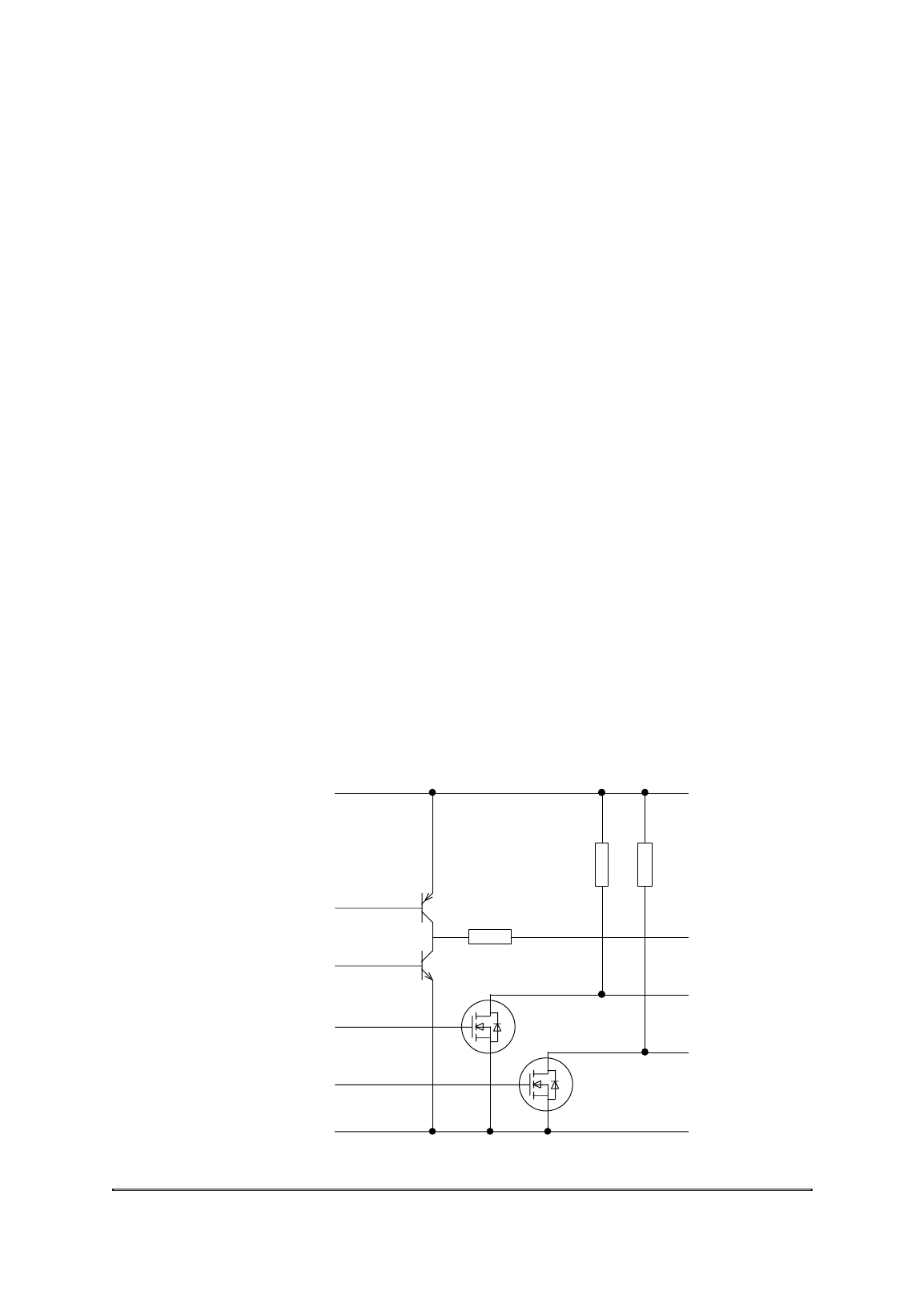
up - it can be driven high or low by the Reader, and can also float in
a high impedance state as shown in the diagram below.
The diagram below shows the logical implementation of the data
outputs:
D0
D1
DA
+5V
0V
0V
10k 10k
47R

Proximity Readers Handbook
4-2
The polarities of the three data outputs (D0, D1 and DA) are all
active-low.
Data Hold input
With the Wiegand and Magnetic Stripe interfaces, the Data Hold
input (H) can be used by the host to buffer one data message in the
Reader until the host is ready to read it. This enables the data lines
from two Readers to be connected in parallel, the host polling each in
turn by releasing its Data Hold input, reading the data, then
asserting the Data Hold input again. The Reader will store the
message until the next card is read.
With the ASCII/TTL interface, the Data Hold input (H) is used as the
CTS input to the Reader.
Wiegand
Connections
The pin connections for the Wiegand interface are as follows:
0V (ground)
D0 (logic 0)
D1 (logic 1)
DA (data available)
Electrical characteristics
The interface provides three outputs: logic zero data (D0), logic one
data (D1) and data available (DA).
Data transfer is performed by pulsing the D0 line to indicate a logic
zero and by pulsing the D1 line to indicate a logic one. The pulses are
active-low. The voltage of the data lines is +5V or 0V.
The Data Available output (DA) is provided to tell the host system it
must read a data message from the Reader. If the Data Hold input
(see above) is not active, DA becomes active 1ms before data is sent
and is released 1ms after the data has been sent. If the Data Hold
input is active, DA becomes active but data is not sent until Data
Hold is released, DA remaining active until 1ms after the data has
been sent. When used in association with the Data Hold input (see
above), DA enables the data lines from two Readers to be connected
in parallel. The polarity of the DA output is active-low.
Data interfaces
4-3
Data format
There are three aspects to the format of the data message, all of
which can be varied, depending on the interface number you use:
• Framing bits at the start and finish of the message.
• Any parity bits which may be used.
• The data from the card.
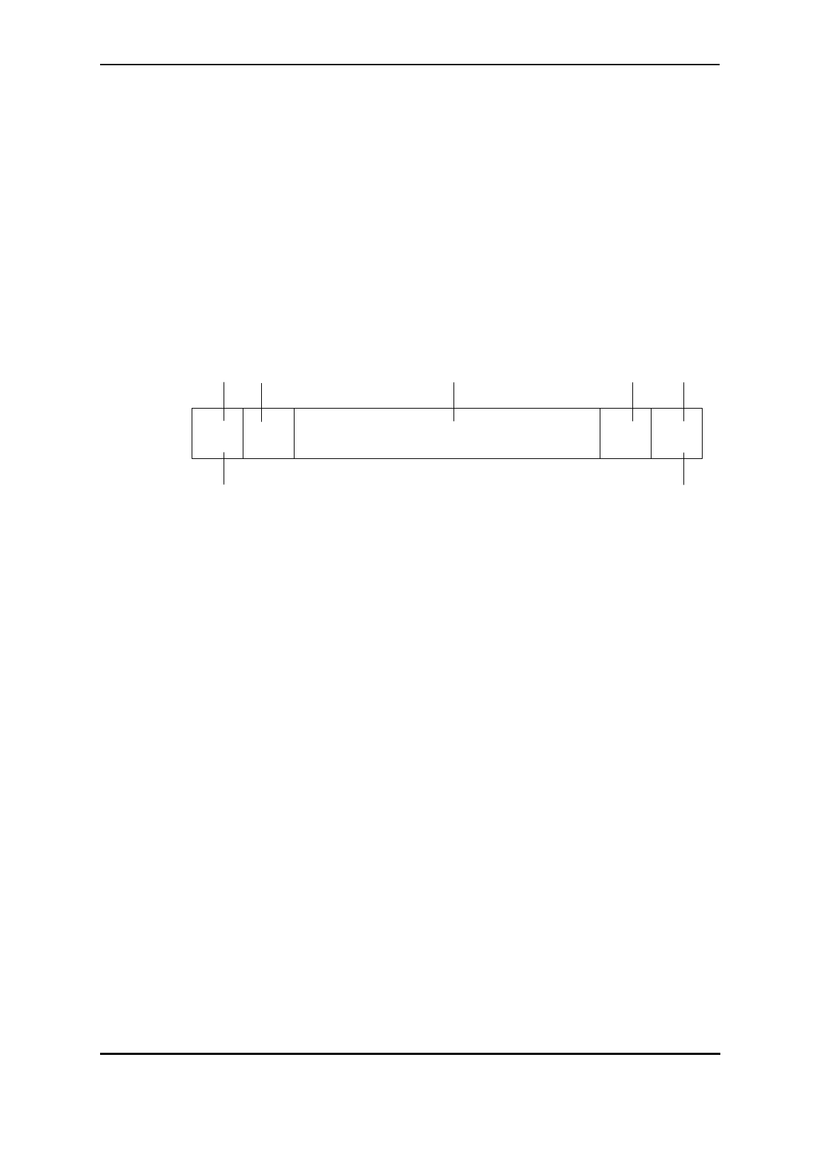
The following diagram shows a typical message structure.
LSB
Data Framing
Transmitted last
Framing
Transmitted first
Trailing
Parity
Leading
Parity
MSB
Framing bits are usually either not used or confined to start and stop
bits which have a fixed state.
Parity bits are used to check the integrity of the data message. Parity
may be odd or even and it may be calculated from the data only or
from the data and some framing bits. The Reader can calculate the
leading parity bit based on the first 13 bits of 26-bit Wiegand format
if you require, see chapter 3.
Card data
Data from the card can be any number of bits up to a maximum of
48. This includes any parity check bits which may be stored in the
card code. The interface selected also determines whether the data is
sent most significant bit first or least significant bit first.
Proximity Readers Handbook
4-4
Interface settings
All other options to do with the Wiegand interface such as variation of
pulse width and interval are selected using the interface number
programmed into the configuration card (see chapter 3). The following
diagram shows some typical timings for a Wiegand interface:
Data 0
Data 1
<><>><>< interval pulse interval pulse
DA 1ms 1ms
The following Wiegand data outputs are available:
Interface
Number Function
02 lower 32 bits of data msb first,
100µs pulse, 400µs space
04 start bit 1, lower 32 bits of data lsb first, stop bit 0,
50µs pulse, 2ms space
0E lower 25 bits of data msb first, trailing parity bit,
50µs pulse, 450µs space
12 leading parity bit (if configured), lower 24 bits of data msb first,
trailing parity bit, 50µs pulse, 3ms space
(use for “standard” 26-bit Wiegand)
24 data bit 32, four zeros, lower 31 bits of data msb first,
50µs pulse, 1.2ms
59 4101/4010 Controller interface - use when connecting to
4422 swipe module or 4010 swipe Controller
- set 4101/4010 Controller to interface 303
Note: if you cannot use one of the above data output formats then
you need to use a different Reader such as the 5311 driving a PR100,
HD100, SP100 or PM100 Reading Head.

Data interfaces
4-5
Magnetic Stripe
A Magnetic Stripe interface is provided which simulates the output of
a magnetic card reader.
Connections
The pin connections for the Magnetic Stripe interface are as follows:
0V (ground)
D0 (data)
D1 (strobe)
DA (present)
Electrical characteristics
The interface provides three outputs: Present, Data and Strobe.
Present is a signal given by a magnetic card reader indicating that a
card has been inserted in the slot. On the Proximity Readers, this
signal becomes active just before data is sent and is released after the
data has been sent. The polarity of the signal is active-low.
Data is a signal whose level reflects the value of the bit in the code.
The polarity of the signal is “inverse logic”, which means a high signal
indicates a zero and a low signal indicates a one.
Strobe is a series of clock pulses. The polarity of the signal is active-
low. Data can be sampled on either the rising edge or the falling edge
of the Strobe signal.
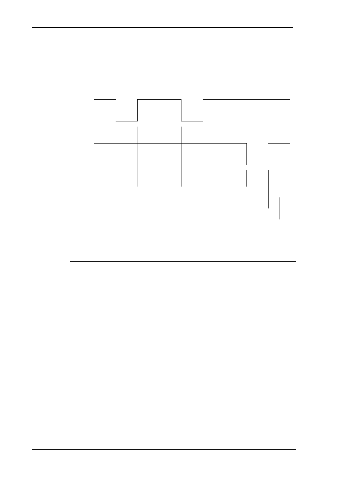
The following diagram should make clear the action of all three
signals in a data transfer:
Present (DA)
Data (D0)
Strobe (D1)
Card number 0 0 010111

Proximity Readers Handbook
4-6
The following diagram shows the format of the Magnetic Stripe
output:
start bits
(8 zeros) stop bits
(8 zeros)
data characters
(low bit first, parity last)
Longitudinal Redundancy Check
end character
(hex F)
start character
(hex B)
most significant character
00000000 11010 1248P 1248P 1248P 1248P 11111 LRC 00000000
This example shows an output of 4 data characters only - all of the
Mag Stripe interfaces which are available on the Proximity Readers
output 10 or 11 data characters as shown below.
The following Mag Stripe data outputs are available:
Interface
Number Function
47 5 Secondary Code characters (Secondary Code not checked),
5 data characters (lower 16 bits of data),
1.5ms bit period, 500µs strobe
4D 5 Secondary Code characters, insert character “6”,
5 data characters (middle 16 bits of lower 32 bits of data),
1.5ms bit period, 500µs strobe
4E 5 Secondary Code characters, insert character “6”,
5 data characters (lower 16 bits of data),
1.5ms bit period, 500µs strobe
4F 5 Secondary Code characters,
5 data characters (lower 16 bits of data),
1.5ms bit period, 500µs strobe
BE with bit 32 of the card programmed to 0:
5 Secondary Code characters, 5 data characters,
1.5ms bit period, 500µs strobe
BE with bit 32 of the card programmed to 1:
bottom 31 bits of card code are converted to a decimal number
and are then output as ten data characters,
1.5ms bit period, 500µs strobe
(this interface is used for Bewator IB1 coded cards)
With interface BE (bit 32 programmed to 0) and interfaces 47, 4D, 4E
and 4F, secondary codes from 0 to 65535 and card numbers from 0
to 65535 are each output as five decimal characters, ten characters
in all, Secondary Code first, most significant character first. It is best
to use the Cotag Programmer in DD display format to program the
cards, but even if it is set up in HH and the Secondary Code or card
number contain hexadecimal digits A to F, the card will still work
with the magnetic stripe interface.

Data interfaces
4-7
With interface BE (bit 32 programmed to 1), the bottom 31 bits of
card code are converted to a single decimal number which is then
output as ten characters, most significant character first.
ASCII data output - TTL voltage levels
Connections
The pin connections for the ASCII/TTL interface are as follows:
0V (ground)
D0 (TXD)
DA (RTS)
H (CTS)
Note: you must set the Data Hold input to be active-high - the bit in
the configuration code which selects the Data Hold polarity must be
set to 1 (the h bit in the xxxh field), see chapter 3.
The protocol (number of data bits, parity and baud rate) is defined in
the xbff field in the configuration code, see chapter 3.
Electrical characteristics
This output is at TTL voltage levels (0V/+5V). It can be converted to
RS232 voltage levels using the 5810 RS232 Converter. This consists
of a cable attached to a D-type connector shroud containing the
converter. The pin connections to the 25-way D-type connector on the
5810 RS232 Converter are as follows:
CTS (input to Reader)
0V (ground)
RTS (output from Reader)
TXD (output from Reader)
PIN 14PIN 25
PIN 13 PIN 1
25-way D-type female connector
(viewed from mating side)

Proximity Readers Handbook
4-8
Data format
The following ASCII data outputs are available:
Interface
Number Card data output
60 *hhhhhhhh#
64 *hhhhhhhh#<c/r><l/f>
The output consists totally of ASCII characters:
* is the ASCII asterisk character. It is used to indicate the start of
data.
hhhhhhhhhh is a sequence of ASCII characters representing the
eight hex digits of the 32-bit card number (the lower 32 bits of the tag
code).
# is the ASCII hash character. It is used to indicate the end of data.
<c/r> is the ASCII code for “carriage return” (hex D).
<l/f> is the ASCII code for “line feed” (hex A).
Protocol
The baud rate, start/data/stop bits and parity can be selected by
setting bits in the xbff field in the configuration code, see chapter 3.
4101/4010 Controller interface
The Readers can be connected to a 4422 swipe card module installed
in a 4101 or 4010 Controller, or directly to a 4010 swipe Controller,
the pin connections being as follows:
Reader 4422 swipe module or 4010 swipe Controller
D0 D0
D1 D1
0V 0V
Interface
Number Function
59 Wiegand output to 4422 swipe module
or 4010 swipe Controller

5-1
Chapter 5
Operation
Once you have set up all the options described in chapter 3, “Setting
up”, normal operation simply consists of presenting your card or tag
to the Reader and awaiting the response. The Readers are always
used in conjunction with a host system which controls the door lock
mechanism and takes decisions about when to activate it.
LEDs
Under internal control (LEDs driven by the Reader), the green LED
lights when the Reader detects the presence of a valid card and stays
green for the hold off time, or for as long as a card is within range of
the antenna. The red LED lights when there is no valid card in range,
unless there is too much electrical noise in the reading area in which
case the amber LED flashes.
Under single wire control (red and amber LEDs driven by the Reader,
green LED driven by host), the host lights the green LED when it has
verified the card number and unlocked the door. When the host
releases the green LED control, the green LED goes off and the red
LED lights. If there is too much electrical noise in the reading area
the amber LED flashes.
Under external control (LEDs driven by host), the green and red LEDs
light when their respective connections are pulled low by the host.
Card interrogation
Standard interrogation routine
When the Reader detects a card, it reads all 64-bits of code in one
burst. The security codes are checked against those stored in the
Reader (which were read from the DC/SC configuration card, see
chapter 3). If they are valid then a data message is transmitted via
the selected interface. (Note that interfaces 47, 59, BC and BE do not
check the Secondary Code before outputting data.)
After the card code has been read successfully, polling is suppressed
altogether for a period called the “hold-off time”. This time is specified
in the configuration card (see chapter 3).

Proximity Readers Handbook
5-2
If the card remains in range of the Reader after the hold-off time, so is
read more than once, no further data messages are transmitted until
a period of time has elapsed called the “repeat data delay” (RDD).
This time is set to a value specified in the configuration card (see
chapter 3).
The length of time between the card being detected by the Reader and
the data being transmitted to the host is 0.4 seconds for standard
cards, and 0.1s for fast cards.
Using cards
Because the Proximity Readers are very small, they are designed for
use with a hand-held card. Present the face of the card near the
Reader and wait for the green light to come on.
Looking after a card
• Don’t let the card get too hot - for example if left in a car on a
sunny day. The operating temperature range for the card is
-20 to +50oC.
• Don’t let the card get wet and especially not submerged. Don’t
send your card to the laundry!
• Don’t deliberately bend the card and take care not to sit on it
in your pocket.
• Do not dispose of the card in a fire.
• To clean the card, use a damp cloth. Don’t use any solvents
and don’t immerse it in anything.
D01481_2 PR500-2 R&TTE DoC

D01521_1 HD500-2 SP500 PM500 R&TTE DoC