Beyerdynamic QUINTACU Conference system Quinta User Manual Quinta System BA EN neu
Beyerdynamic Conference system Quinta Quinta System BA EN neu
UserManual.wiki
>
Beyerdynamic
>
QUINTACU User Manual
UserManual.pdf
Navigation menu
Upload a User Manual
Namespaces
Wiki Guide
HTML
PDF
Info
Views
User Manual
Discussion / Help
Navigation

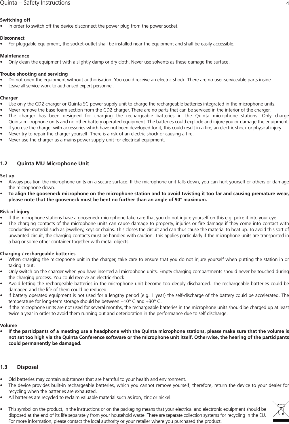
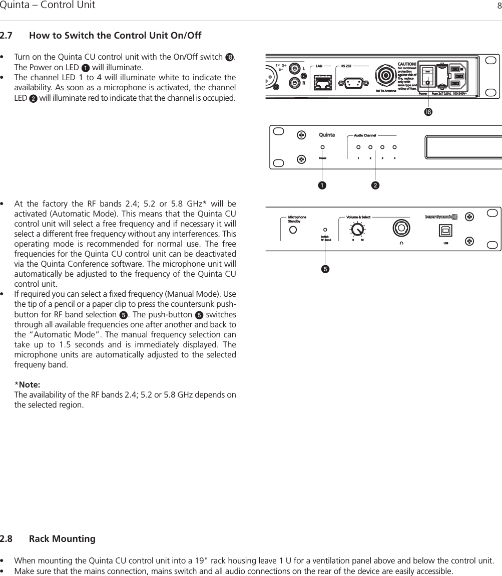
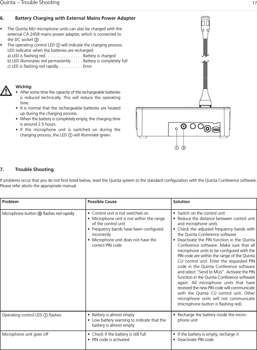
![2. Quinta CU Control UnitThe Quinta CU control unit is the heart of the system. It controls the delegate and chairman microphone units. With one control unit a maxi-mum of 4 speakers (e.g. 3 delegates and 1 chairman) can speak simultaneously. The radio transmission is in the triple band (2.4 / 5.2 / 5.8 GHzfrequency band).The control unit has been designed for installations on tables or 19" rack mounting. When setting up the system, please follow the safety instructions mentioned in chapter 1. Furthermore, please note• the ambient temperature of the installation site must not exceed 40 °C [104 °F]. • there must not be exceeding dust and humidity a the installation site.• that the unit is not exposed to direct sunlight.• the connection must be protected against direct access during operation.• that there must be a strain relief of the cables.• the installation site must be protected against vibrations.2.1 Controls and IndicatorsPower on LEDAudio channel LEDs 1 to 4 (white = channel vacant; red = channel occupied)Display to indicate operating mode, channel, headphone volumeStandby button to turn off all microphone units centrallyPush-button for frequency band selection Volume control for headphone / channelHeadphone connectionUSB connectionAntenna connectionsAVB (Audio Video Bridging) network connection for digital audio signals via CAT5 cables, RJ45Audio input (Audio IN) for the connection of external sound sources, 3-pin Phoenix terminal strip, balancedAudio output, individual channels, 4 x 3-pin Phoenix terminal strips, balancedAudio output Mix (Master), 3-pin Phoenix terminal strips, balancedAudio output Mix (Master), 3-pin XLR, balanced Audio output Mix (Master), RCA, unbalanced LAN connection for PC / network, RJ 45Connection for media control system / PC / network, RS 232On/Off switchFuseMains connectionQuinta – Control Unit 5FrontRear ](https://usermanual.wiki/Beyerdynamic/QUINTACU/User-Guide-1841524-Page-5.png)
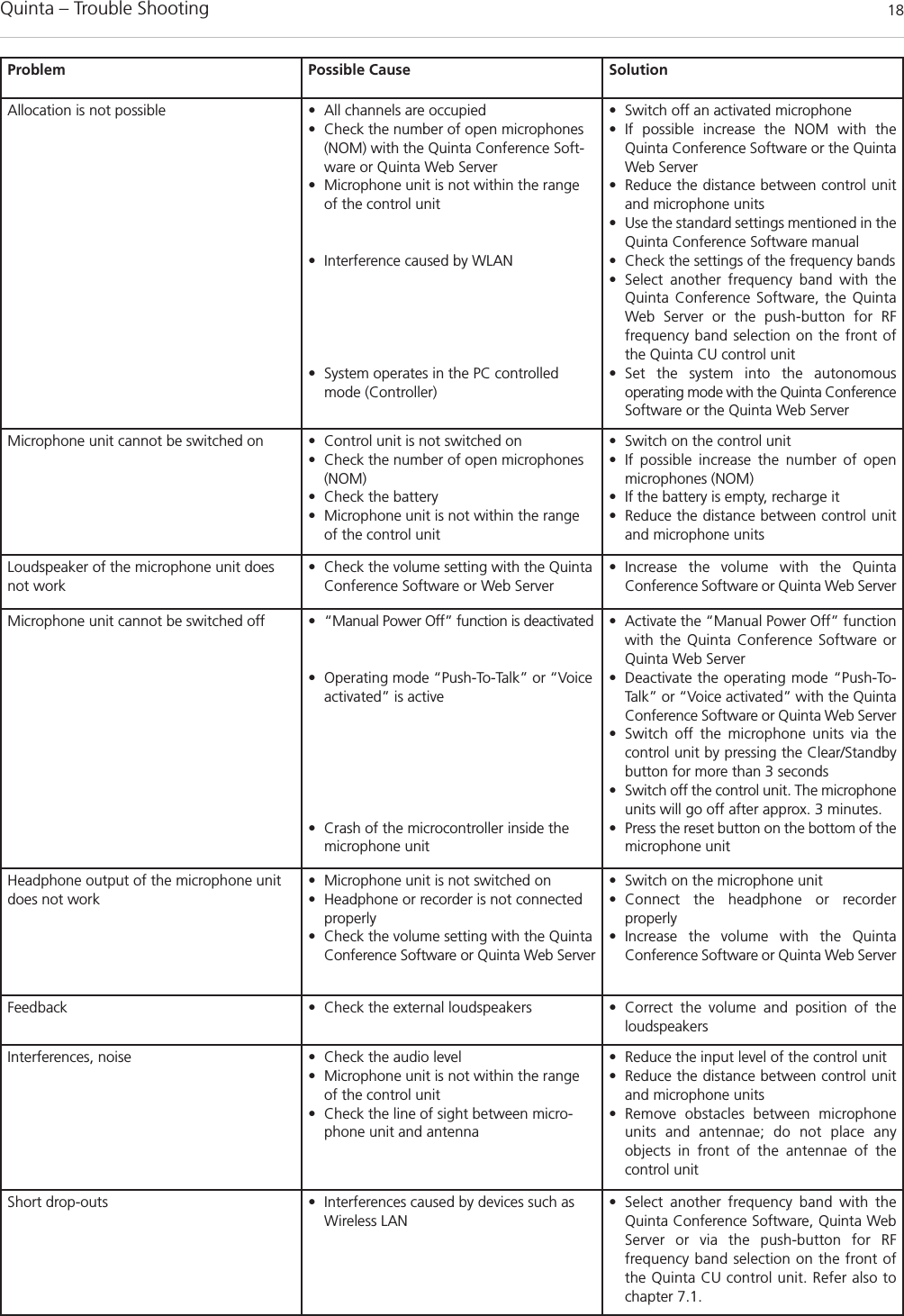
![Quinta – Control Unit 6 Important:• There must be an unobstructed path between the microphone units and the antennae, i.e. between the Quinta CU control unit or the remote antennae and the microphone units there must not be any obstacles. With a free line of sightbetween the control unit and the microphone units and the rod antennae the range is between 30 to 50 m [98.4 ft to 164 ft].For optimum range the surface of the table is important, wood or plastic tables are ideal, but metal tables can cause interferencesand reduce the range. • Please make sure that with a free line of sight the minimum distance between the antennae and the microphone units is notless than 1 m [3.2 ft]. 2.3 How to Connect the Antennae2.3.1 Direct Connection• Connect the antennae to the antenna connections . Please note that for diversity operation both antennae have to be connected! A weighting circuit is used to make sure that the better antenna signal is received. • For stand-alone operation we recommend using the supplied CA Q 11 angled rod antennae.2.3.2 Remote Connection• The Quinta CU control unit can also be operated with remote antennae. We recommed extremely low attenuation connecting cables whichare 10 m [32.8 ft] or 20 m [65.6 ft] long. Please note that the antennae have to be installed remotely. 2.2 Where to Place the Control Unit• If you do not use remote antennae, place the Quinta CU control unit in the room where the meeting takes place. If you use remoteantennae, place the antennae in the conference room.• Avoid shadowing effect of the antennae, especially by metallic surfaces.• A free line of sight between the Quinta MU microphone units and the antennae of the Quinta CU control unit is essential for the operation ofthe microphone units. Big obstacles in between can possibly affect the radio transmission. In such specific installations the use of remoteantennae can possibly achieve an improvement of the RF situation.• If you want to install several Quint CU control units in a 19" rack, please make sure that there is a minimum distance of 1 U between thecontrol units to avoid interferences, especially if you do not use remote antennae.](https://usermanual.wiki/Beyerdynamic/QUINTACU/User-Guide-1841524-Page-6.png)
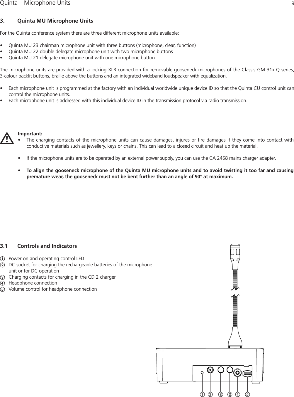
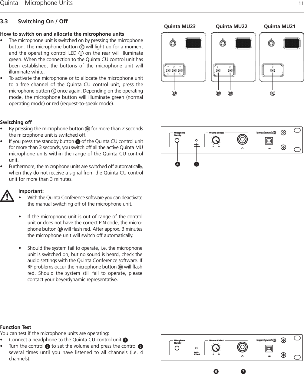
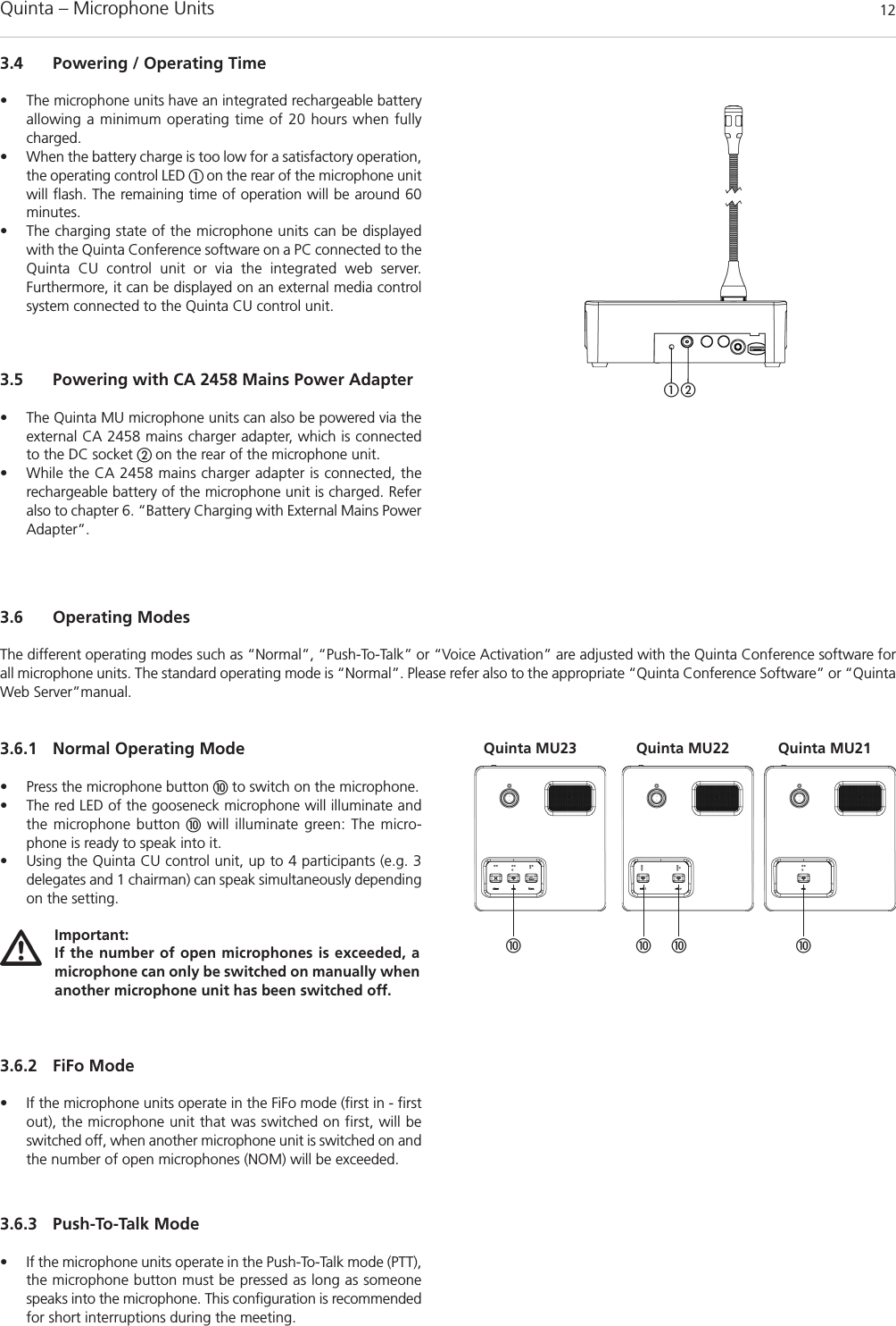
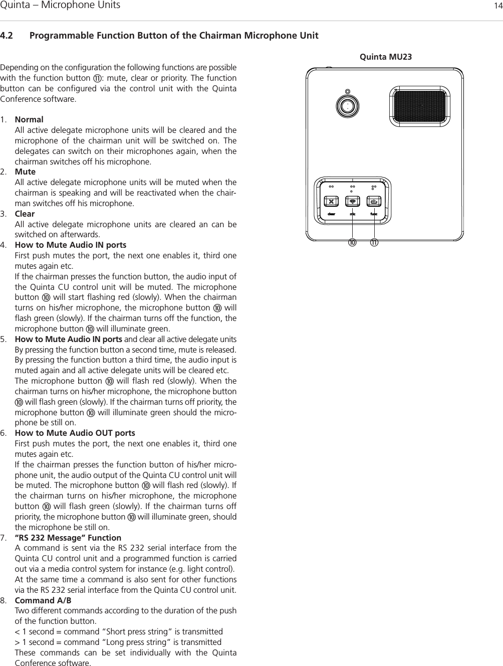
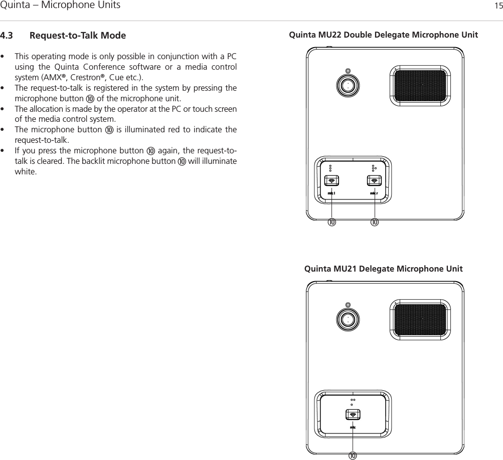
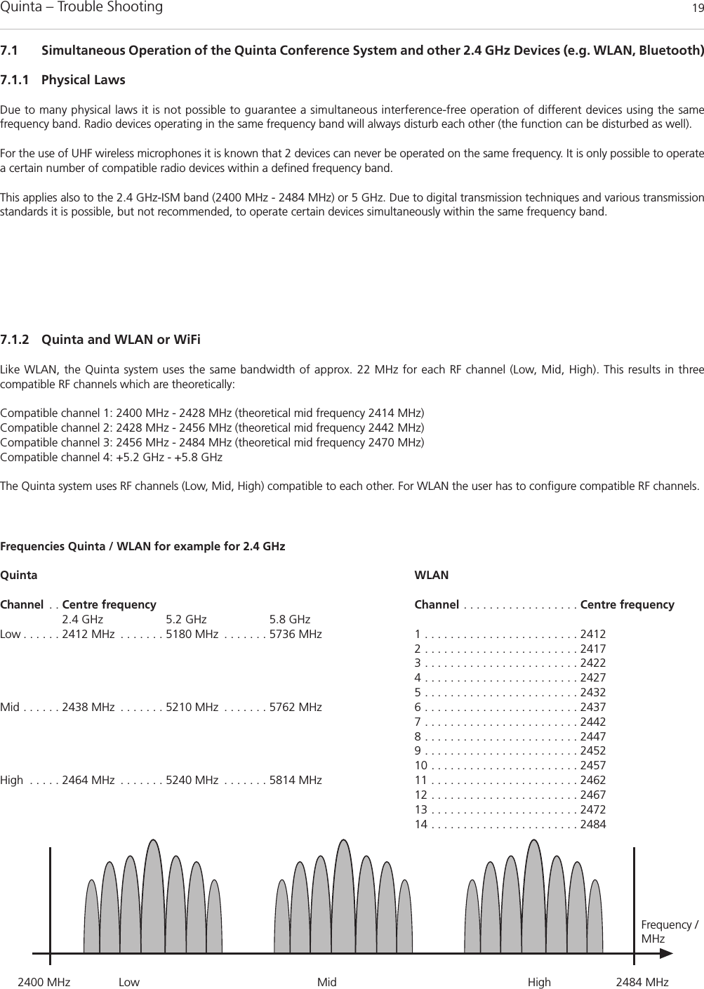
![Quinta – Microphone Units 10Opening for unlocking the gooseneck microphoneConnection for gooseneck microphoneLoudspeaker“Clear” button to clear all delegate microphone unitsMicrophone button!Programmable function button"Reset button to restart the integrated microcontroller (referalso the item “Microphone unit cannot be switched off” inchapter 7. “Trouble Shooting”)Quinta MU23 Chairman Microphone Unit Quinta MU22 Double Delegate Microphone UnitQuinta MU21 Delegate Microphone Unit!Bottom of Microphone Unit"3.2 How to Connect the Gooseneck MicrophoneThe following gooseneck microphones with an LED are available toconnect to the microphone unit.– Classis GM 313 Q; 300 mm [11.81"] in length– Classis GM 314 Q; 400 mm [15.75"] in length– Classis GM 315 Q; 500 mm [19.69"] in length– Classis GM 316 Q; 600 mm [23.62"] in length• Take the gooseneck microphone by the shaft, put it into theconnection for gooseneck microphones and press the shaftdownwards until it locks in place. • If you want to remove the gooseneck microphone, press intothe opening for unlocking the gooseneck microphone withthe supplied tool or a similar thin tool. Remove the gooseneckmicrophone by taking it by the shaft and pulling.](https://usermanual.wiki/Beyerdynamic/QUINTACU/User-Guide-1841524-Page-10.png)
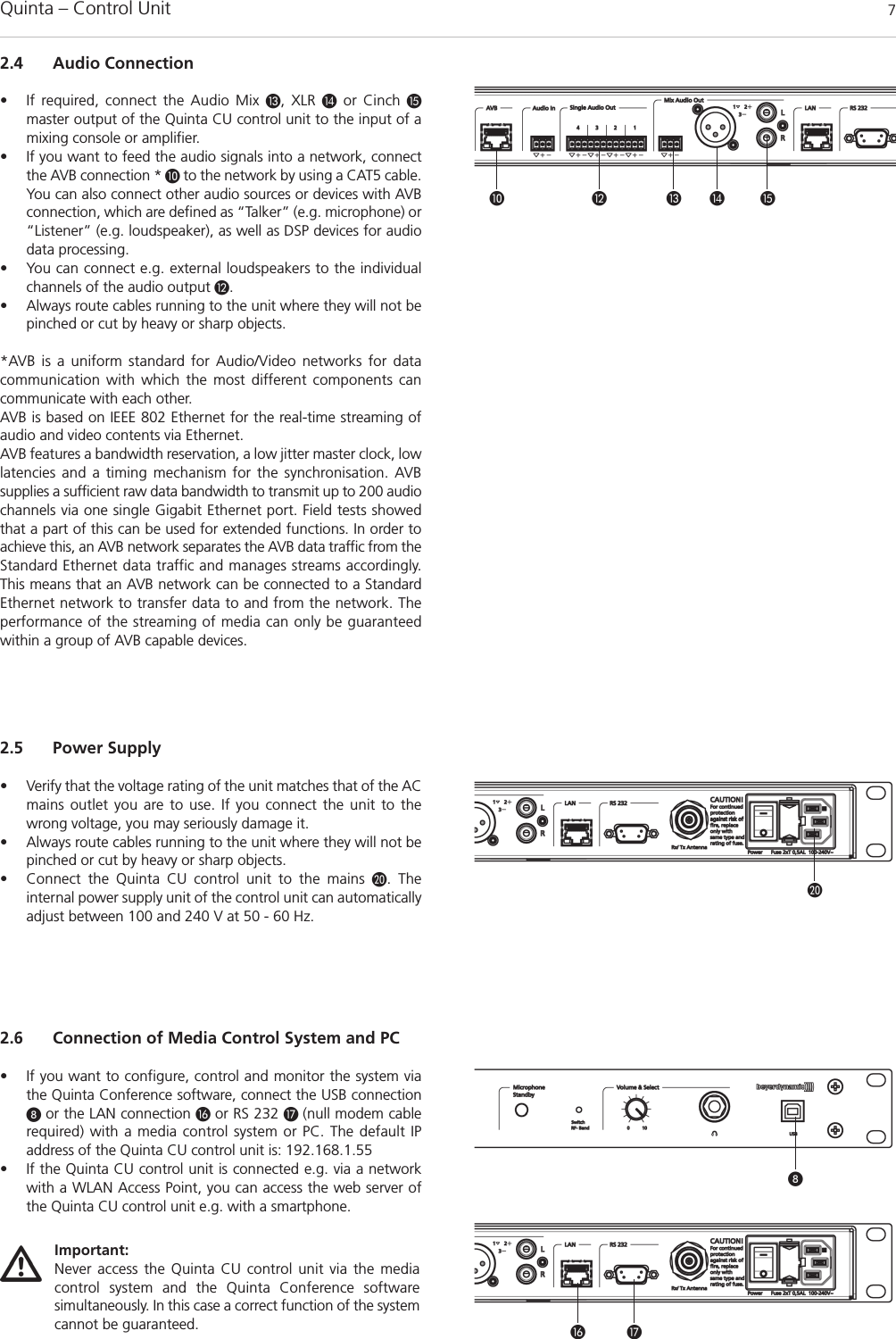
![Quinta – Components 219. AccessoriesSupplied Accessories1 Power cable1 USB cable6 Phoenix terminal strips, 3-pin2 CA Q11 antennas1 Unlocking toolQuinta Conference Software for Control and Configuration. . . . . . . . . . . . . . . . . . . . . . . . . . . . . . . . . . . . . . . . . . . . . . . . . Order # 723.991OptionalQuinta CU Control UnitCA Q 13 Planar antenna, 2.4 - 5.8 GHz . . . . . . . . . . . . . . . . . . . . . . . . . . . . . . . . . . . . . . . . . . . . . . . . . . . . . . . . . . Order # 724.408CA Q 14 Omnidirectional antenna for remote installation . . . . . . . . . . . . . . . . . . . . . . . . . . . . . . . . . . . . . . . . . . . . . Order # 723.894CA Q 30 Ecoflex system coaxial cable, sold per metre . . . . . . . . . . . . . . . . . . . . . . . . . . . . . . . . . . . . . . . . . . . . . . . . Order # 724.440CA Q 31 Ecoflex system coaxial cable, 10 m [32.8 ft] . . . . . . . . . . . . . . . . . . . . . . . . . . . . . . . . . . . . . . . . . . . . . . . . Order # 724.416CA Q 32 Ecoflex system coaxial cable, 20 m [65.6 ft] . . . . . . . . . . . . . . . . . . . . . . . . . . . . . . . . . . . . . . . . . . . . . . . . Order # 724.424Gooseneck Microphones for the Quinta MU 23/22/21 Microphone UnitsClassis GM 313 Q Gooseneck microphone, condenser, cardioid, black, length 300 mm [11.81"], LED, 5-pin XLR connector,incl. wind shield . . . . . . . . . . . . . . . . . . . . . . . . . . . . . . . . . . . . . . . . . . . . . . . . . . . . . . . . . . . . . . . . . . . . . Order # 724.203Classis GM 314 Q Gooseneck microphone, condenser, cardioid, black, length 400 mm [15.75"], LED, 5-pin XLR connector,incl. wind shield . . . . . . . . . . . . . . . . . . . . . . . . . . . . . . . . . . . . . . . . . . . . . . . . . . . . . . . . . . . . . . . . . . . . . Order # 724.211Classis GM 315 Q Gooseneck microphone, condenser, cardioid, black, length 500 mm [19.69"], LED, 5-pin XLR connector,incl. wind shield . . . . . . . . . . . . . . . . . . . . . . . . . . . . . . . . . . . . . . . . . . . . . . . . . . . . . . . . . . . . . . . . . . . . . Order # 724.238Classis GM 316 Q Gooseneck microphone, condenser, cardioid, black, length 600 mm [23.62"], LED, 5-pin XLR connector,incl. wind shield . . . . . . . . . . . . . . . . . . . . . . . . . . . . . . . . . . . . . . . . . . . . . . . . . . . . . . . . . . . . . . . . . . . . . Order # 724.351Quinta CC 2 | CC 2 / 600 Charging and Transport CaseQuinta CD 2 Charger for 10 Quinta MU 23/22/21 microphone units. . . . . . . . . . . . . . . . . . . . . . . . . . . . . . . . . . . . . . . . Order # 723.975Quinta CM 2 19" compartment for Quinta CU control unit. . . . . . . . . . . . . . . . . . . . . . . . . . . . . . . . . . . . . . . . . . . . . . . Order # 724.661Quinta CS 2 Empty compartment for Quinta CU control unit or accessories . . . . . . . . . . . . . . . . . . . . . . . . . . . . . . . . . . Order # 724.688Quinta CT 2 Top cover . . . . . . . . . . . . . . . . . . . . . . . . . . . . . . . . . . . . . . . . . . . . . . . . . . . . . . . . . . . . . . . . . . . . . . . . . . Order # 724.556Quinta CT 2/600 Top cover, when using the microphone units with the Classis GM 316 Q microphone. . . . . . . . . . . . . . . . . Order # 724.5808. ComponentsQuinta CU Control unit, DSSS transmission in 2.4 / 5.2 / 5.8 GHz ISM bands,4 receive channels, 19" housing, 1 U, incl. 2 angled rod antennae,matt black, with high-resolution OLED display . . . . . . . . . . . . . . . . . . . . . . . . . . . . . . . . . . . . . . . . . . . . . . Order # 723.924Quinta MU23 Chairman microphone unit, removable Classis GM 31xQ gooseneck microphone (optional),DSSS transmission (Triple-RF-ISM-Band), incl. rechargeable battery, with loudspeaker and three buttons, soft touch paint, matt black . . . . . . . . . . . . . . . . . . . . . . . . . . . . . . . . . . . . . . . . . . . . . . . . . . . . . . . . . . . . Order # 723.932Quinta MU22 Double delegate microphone unit, removable Classis GM 31xQ gooseneck microphone (optional),DSSS transmission (Triple-RF-ISM-Band), incl. rechargeable battery, with loudspeaker and two microphone buttons, soft touch paint, matt black. . . . . . . . . . . . . . . . . . . . . . . . . . . . . . . . . . . . . Order # 723.940Quinta MU21 Delegate microphone unit, removable Classis GM 31xQ gooseneck microphone (optional),DSSS transmission (Triple-RF-ISM-Band), incl. rechargeable battery, with loudspeaker and one microphone button, soft touch paint, matt black . . . . . . . . . . . . . . . . . . . . . . . . . . . . . . . . . . . . . Order # 723.959Quinta CC 2 Charging case for 10 Quinta MU 23/22/21 microphone units with GM 313/314/315 Q, consisting of: Quinta CT 2 top cover, Quinta CD 2 charger, Quinta CW 2 bottom with casters . . . . . . . . . . . . . . . . . . . . . Order # 723.967Quinta CC 2/600 Charging case for 10 Quinta MU 23/22/21 microphone units with Classis GM 316 Q, consisting of: Quinta CT 2 / 600 top cover, Quinta CD 2 charger, Quinta CW 2 bottom with casters . . . . . . . . . . . . . . . . Order # 724.580CA 2458 Mains power adapter with charging function and DC power supply for one Quinta MU microphone unit . . . . Order # 723.983](https://usermanual.wiki/Beyerdynamic/QUINTACU/User-Guide-1841524-Page-21.png)
![Quinta – Technical Specifications 2210. Technical SpecificationsGeneralFrequency range . . . . . . . . . . . . . . . . . . . . . . . . . . . . . . . . . . . 2400 – 2483.5 MHz 5150 – 5250 MHz5725 – 5875 MHzModulation. . . . . . . . . . . . . . . . . . . . . . . . . . . . . . . . . . . . . . . Direct Sequence Spread Spectrum DSSS (2.4 GHz; 5.8 GHz); Orthogonal Frequency Division Multiplexing OFDM (5.2 GHz)digital signal processing acc. to own standardMax. number of audio streams . . . . . . . . . . . . . . . . . . . . . . . . 4 useable channels per system Signal-to-noise ratio . . . . . . . . . . . . . . . . . . . . . . . . . . . . . . . . 80 dB typ., (unweighted signal-to-noise ratio)Range between microphone units and control unit . . . . . . . . . > 100 m [109.36 yds]Power supply . . . . . . . . . . . . . . . . . . . . . . . . . . . . . . . . . . . . . 100 – 240 V AC 50/60 HzApproval. . . . . . . . . . . . . . . . . . . . . . . . . . . . . . . . . . . . . . . . . world-wideAVBTransmission and reception of audio data . . . . . . . . . . . . . . . . . . . . . . . . . . . . . . . . . . . . . acc. to IEC 61883-6Format of the audio data . . . . . . . . . . . . . . . . . . . . . . . . . . . . AM824Stream ID Quinta CU . . . . . . . . . . . . . . . . . . . . . . . . . . . . . . . Bit 63 – 16 / MAC address Bit 15 – 0 / X Quinta MU Microphone UnitsTransmitter power. . . . . . . . . . . . . . . . . . . . . . . . . . . . . . . . . . max. 20 dBm per channel and region (average, duty cycle ≤ 30%)*Battery voltage . . . . . . . . . . . . . . . . . . . . . . . . . . . . . . . . . . . . 8 NiMH cells, 2080 mAhExternal DC operation. . . . . . . . . . . . . . . . . . . . . . . . . . . . . . . 15 V DC (±0.5 V), residual hum < 20 mV, 950 mA Charging time with charger . . . . . . . . . . . . . . . . . . . . . . . . . . max. 2.5 hours when the battery is completely emptywith mains charger adapter . . . . . . . . . . . . . . . . . . . . . . . . . . max. 2.5 hours when the battery is completely emptyLoudspeaker . . . . . . . . . . . . . . . . . . . . . . . . . . . . . . . . . . . . . . Wide-band, integrated loudspeakerVolume decrease when Mic On (“Ducking”) . . . . . . . . . . . . . . 15 dB fixed settingHeadphone output . . . . . . . . . . . . . . . . . . . . . . . . . . . . . . . . . Jack socket (3.5 mm, stereo)Min. impedance . . . . . . . . . . . . . . . . . . . . . . . . . . . . . . . . . . . 16 ΩPower supply . . . . . . . . . . . . . . . . . . . . . . . . . . . . . . . . . . . . . 9.6 V with integrated NiMH battery (8 cells) Operating time depending on the type ofthe microphone unit . . . . . . . . . . . . . . . . . . . . . . . . . . . . . . . . approx. 20 hours in discussion mode, operating time also depends on the volume Temperature range (at < 90% humidity) . . . . . . . . . . . . . . . . . +10° – +40°C [+50 °F – +104 °F] Storage temperature (at < 90% humidity) . . . . . . . . . . . . . . . -20° – +55°C [-4 °F – +131 °F] Dimensions (without microphone)Length . . . . . . . . . . . . . . . . . . . . . . . . . . . . . . . . . . . . . . . . . . 173 mm [6.8"]Width . . . . . . . . . . . . . . . . . . . . . . . . . . . . . . . . . . . . . . . . . . . 157 mm [6.18"]Height . . . . . . . . . . . . . . . . . . . . . . . . . . . . . . . . . . . . . . . . . . 51 mm [2.01"]Weight . . . . . . . . . . . . . . . . . . . . . . . . . . . . . . . . . . . . . . . . . . 1.7 kg [3.74 lbs]Quinta CU Control UnitsFrequency response . . . . . . . . . . . . . . . . . . . . . . . . . . . . . . . . 70 Hz – 22 kHz (-3 dB)Operation mode . . . . . . . . . . . . . . . . . . . . . . . . . . . . . . . . . . . Diversity (receiver), separatefor each channelAntenna connection . . . . . . . . . . . . . . . . . . . . . . . . . . . . . . . . 2 N-connectors (female)Transmitting power. . . . . . . . . . . . . . . . . . . . . . . . . . . . . . . . . max. 20 dBm per channel and region (average, duty cycle ≤ 30%)*ConnectionsSerial control port . . . . . . . . . . . . . . . . . . . . . . . . . . . . . . . . . . RS 232, USBEthernet port . . . . . . . . . . . . . . . . . . . . . . . . . . . . . . . . . . . . . LAN, TCP/IP standardMaster output balanced . . . . . . . . . . . . . . . . . . . . . . . . . . . . . 1 x XLR, 1 x 3-pin Phoenix terminal strip, max. +6 dBu,level adjustable via software (range ±15 dB)Master output unbalanced . . . . . . . . . . . . . . . . . . . . . . . . . . . RCA, max. +2.2 dBu, level adjustable via software (range ±15 dB)Audio outputs, single channels . . . . . . . . . . . . . . . . . . . . . . . . 4 x 3-pin Phoenix terminal strip, max. +6 dBu, level adjustable via software (range 0 ... -50 dB)Input balanced . . . . . . . . . . . . . . . . . . . . . . . . . . . . . . . . . . . . 1 x 3-pin Phoenix terminal strip, max. +6 dBu, input adjustable via software(range 0 ... -50 dB)Power supply . . . . . . . . . . . . . . . . . . . . . . . . . . . . . . . . . . . . . 100 – 240 V AC 50/60 Hz 70 – 150 mAFuse . . . . . . . . . . . . . . . . . . . . . . . . . . . . . . . . . . . . . . . . . . . . 2 x AL 0.5 A (slow blow)Power consumption . . . . . . . . . . . . . . . . . . . . . . . . . . . . . . . . 10 VA Temperature range . . . . . . . . . . . . . . . . . . . . . . . . . . . . . . . . . +10° – +40 °C [+50 °F – +104 °F] (at < 90% humidity)Indication . . . . . . . . . . . . . . . . . . . . . . . . . . . . . . . . . . . . . . . . 4 channel LEDs (red/white) and Power LED (red/white)Min. depth of Rack . . . . . . . . . . . . . . . . . . . . . . . . . . . . . . . . . 380 mmDimensions (W x H x D) . . . . . . . . . . . . . . . . . . . . . . . . . . . . . 19", 1HU (440 x 44 x 239 mm) [17.32" x 1.73" x 9.41"]Weight . . . . . . . . . . . . . . . . . . . . . . . . . . . . . . . . . . . . . . . . . . 3.2 kg [7.05 lbs]](https://usermanual.wiki/Beyerdynamic/QUINTACU/User-Guide-1841524-Page-22.png)
![Quinta – Technical Specifications 23AVB interface:MAC address . . . . . . . . . . . . . . . . . . . . . . . . . . . . . . . . . . . . . 00:22:BB:00:FF:FFStream Suffix . . . . . . . . . . . . . . . . . . . . . . . . . . . . . . . . . . . . . 00:00Stream ID . . . . . . . . . . . . . . . . . . . . . . . . . . . . . . . . . . . . . . . . 00:22:BB:00:FF:FF:00:00Number of channels . . . . . . . . . . . . . . . . . . . . . . . . . . . . . . . . 4Audio format . . . . . . . . . . . . . . . . . . . . . . . . . . . . . . . . . . . . . IEC 61883-6/AM824 with 24-bit / 48 kHzIP configuration . . . . . . . . . . . . . . . . . . . . . . . . . . . . . . . . . . . DHCPQuinta CD 2 Charger Power supply. . . . . . . . . . . . . . . . . . . . . . . . . . . . . . . . . . . . . . . . . 100 - 240 V AC ˜, 50 / 60 HzFuse at the mains socket. . . . . . . . . . . . . . . . . . . . . . . . . . . . . 2 x 6.3 A (slow blow)Power consumption . . . . . . . . . . . . . . . . . . . . . . . . . . . . . . . . max. 180 WMax. ambient temperature when charging (< 90% atmospheric humidity) . . . . . . . . . . . . . . . . . . . . . . . . +10 °C – +40 °C [+50 °F – +104 °F]Storage temperature. . . . . . . . . . . . . . . . . . . . . . . . . . . . . . . . -20 °C – +55 °C [-4 °F – +131 °F]Charging unit . . . . . . . . . . . . . . . . . . . . . . . . . . . . . . . . . . . . . 10 microphone units parallelCharging time . . . . . . . . . . . . . . . . . . . . . . . . . . . . . . . . . . . . max. 3.5 hours when the battery is completely emptyDimensions (W x H x D) . . . . . . . . . . . . . . . . . . . . . . . . . . . . . 757 x 476 x 370 mm [29.8" x 18.74" x 14.57"]Weight . . . . . . . . . . . . . . . . . . . . . . . . . . . . . . . . . . . . . . . . . . approx. 12 kgCA 2458 Mains Power Adapter Voltage. . . . . . . . . . . . . . . . . . . . . . . . . . . . . . . . . . . . . . . . . . 15 V DCCurrent carrying capacity . . . . . . . . . . . . . . . . . . . . . . . . . . . . 1.6 AInput voltage . . . . . . . . . . . . . . . . . . . . . . . . . . . . . . . . . . . . . 100 – 240 V AC 50/60 HzConnector . . . . . . . . . . . . . . . . . . . . . . . . . . . . . . . . . . . . . . . Adapter for Europe, USA, UK, Australia*The transmitter power can differ from this value due to specific regulations in various countries.](https://usermanual.wiki/Beyerdynamic/QUINTACU/User-Guide-1841524-Page-23.png)
![Quinta – FCC Regulation 26FCC RegulationFCC ID: OSDQUINTACU for Quinta CUFCC ID: OSDQUINTAMU2X for Quinta MU21FCC ID: OSDQUINTAMU2X for Quinta MU22FCC ID: OSDQUINTAMU2X for Quinta MU23Canada: IC: 3628A-QUINTACU for Quinta CUCanada: IC: 3628A-QUINTAMU2X for Quinta MU21Canada: IC: 3628A-QUINTAMU2X for Quinta MU22Canada: IC: 3628A-QUINTAMU2X for Quinta MU23Part 15.19 StatementNOTICE:This device complies with Part 15 of the FCC Rules [and with RSS-210 of Industry Canada].Operation is subject to the following two conditions:(1) this device may not cause harmful interference, and(2) this device must accept any interference received, including interference that may cause undesired operation.Part 15.21 StatementNOTICE:Changes or modifications made to this equipment not expressly approved by (manufacturer name) may void the FCC authorization to operatethis equipment.Part 15.105 StatementNOTE: This equipment has been tested and found to comply with the limits for a Class B digital device, pursuant to Part 15 of the FCC Rules.These limits are designed to provide reasonable protection against harmful interference in a residential installation. This equipment generates,uses and can radiate radio frequency energy and, if not installed and used in accordance with the instructions, may cause harmful interferenceto radio communications. However, there is no guarantee that interference will not occur in a particular installation. If this equipment does causeharmful interference to radio or television reception, which can be determined by turning the equipment off and on, the user is encouraged totry to correct the interference by one or more of the following measures:• Reorient or relocate the receiving antenna.• Increase the separation between the equipment and receiver.• Connect the equipment into an outlet on a circuit different from that to which the receiver is connected.• Consult the dealer or an experienced radio/TV technician for help.RF Exposure StatementRadiofrequency radiation exposure Information:This equipment complies with FCC radiation exposure limits set forth for an uncontrolled environment.This equipment should be installed and operated with minimum distance of 20 cm between the radiator and your body.This transmitter must not be co-located or operating in conjunction with any other antenna or transmitter.](https://usermanual.wiki/Beyerdynamic/QUINTACU/User-Guide-1841524-Page-26.png)