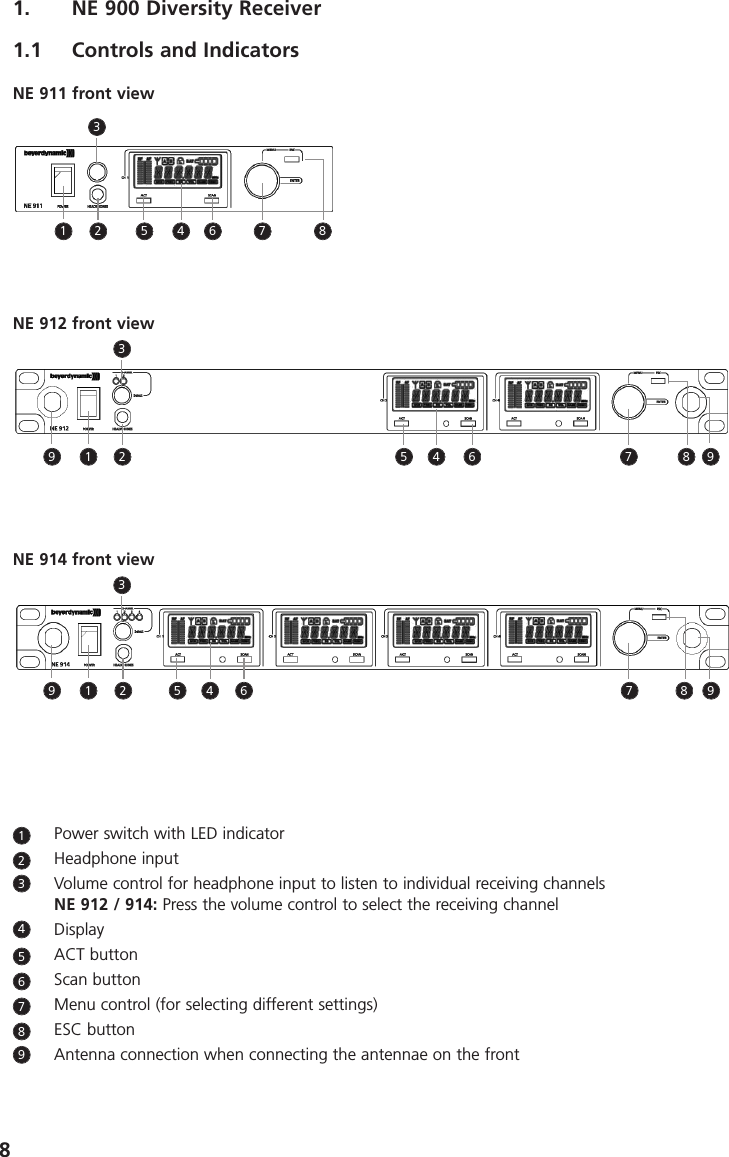
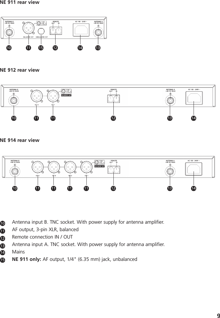
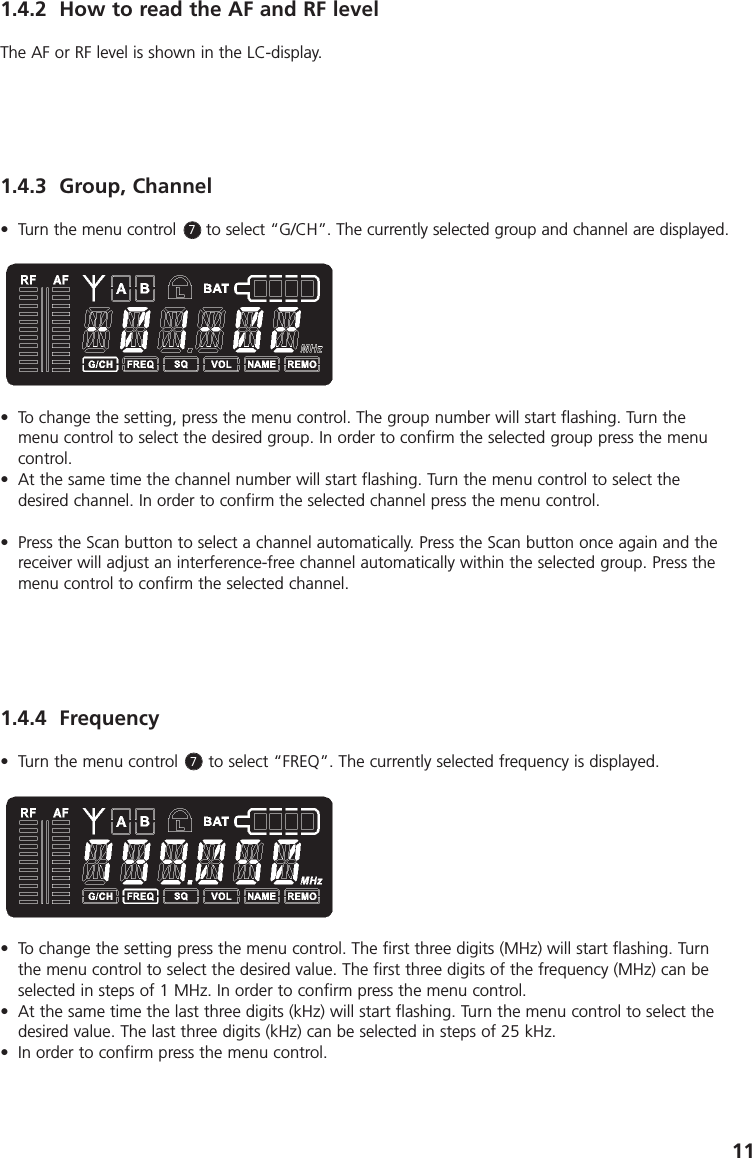
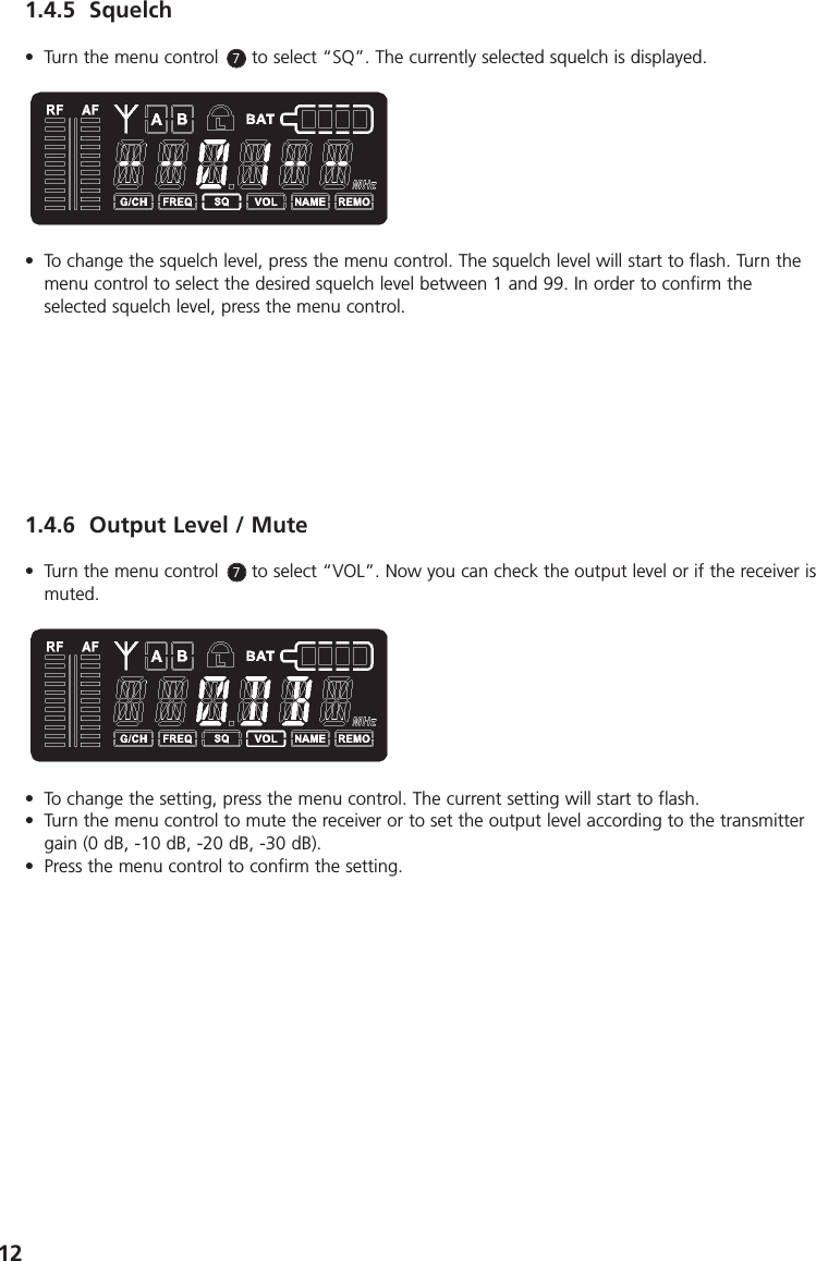
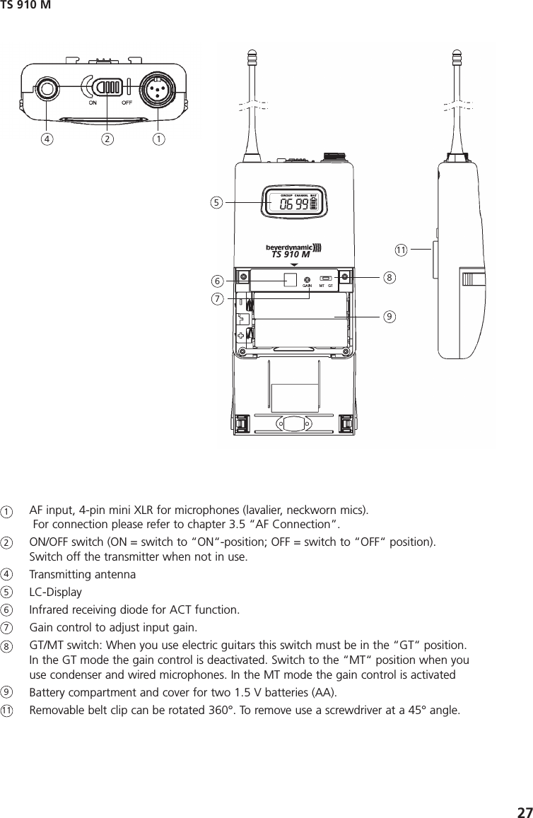
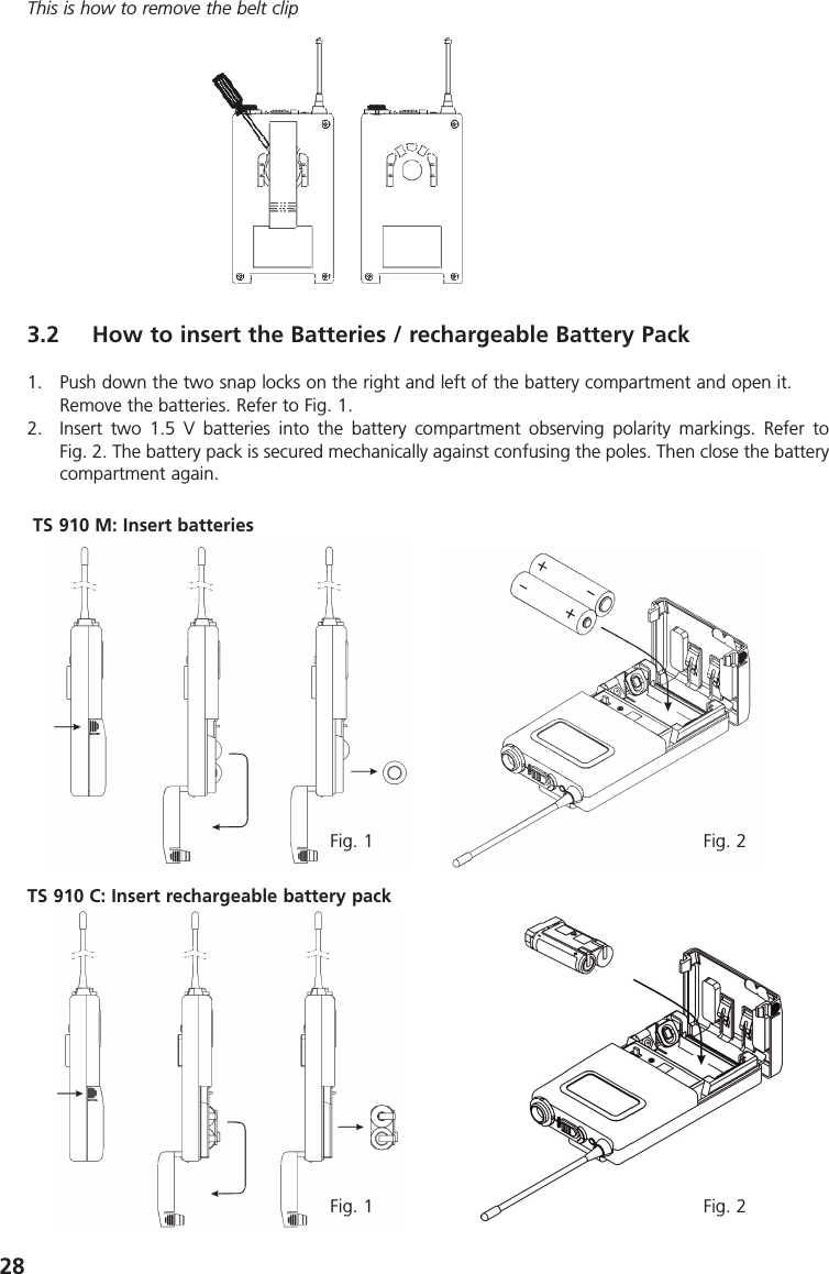
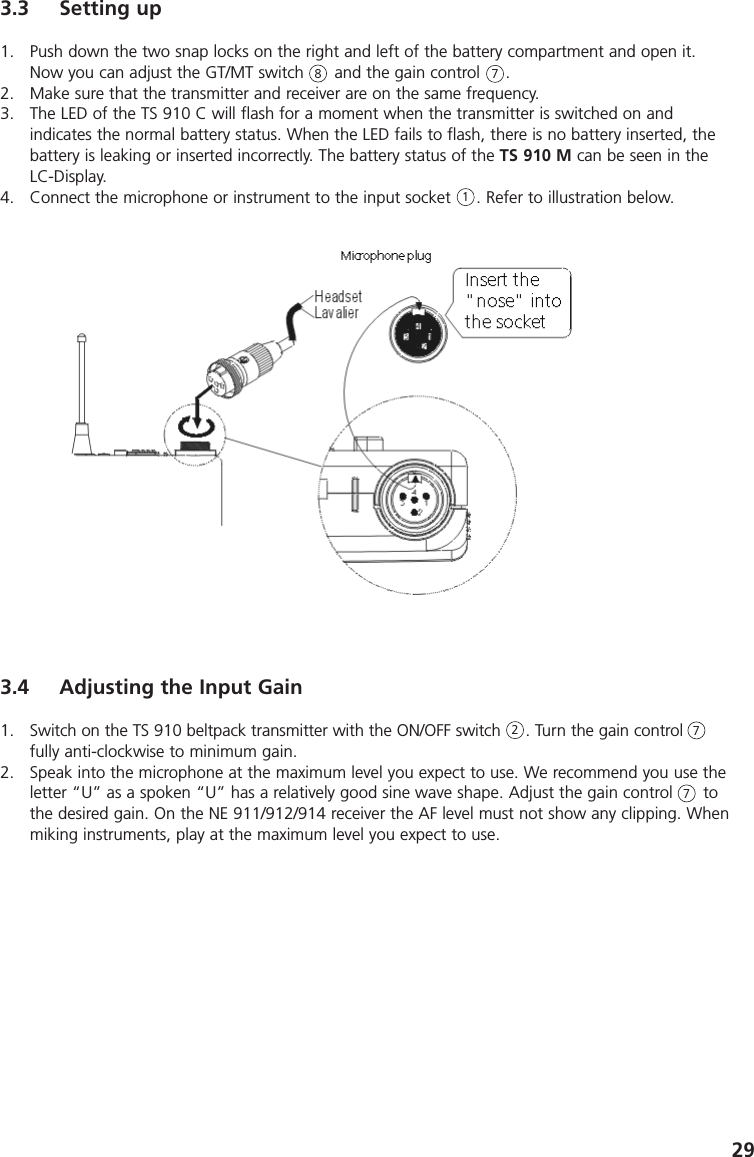
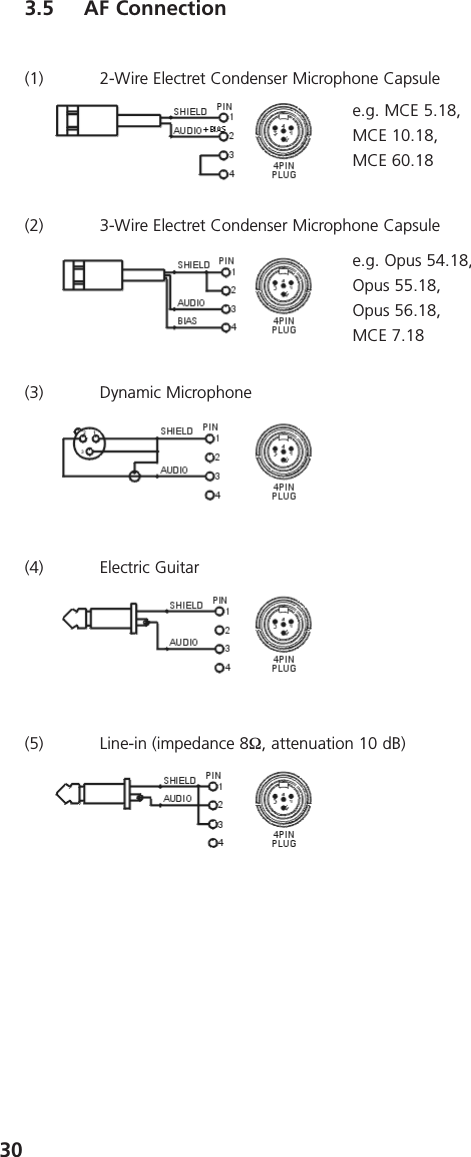
Beyerdynamic TS910 Bodypack transmitter User Manual Opus910 BA USA A1

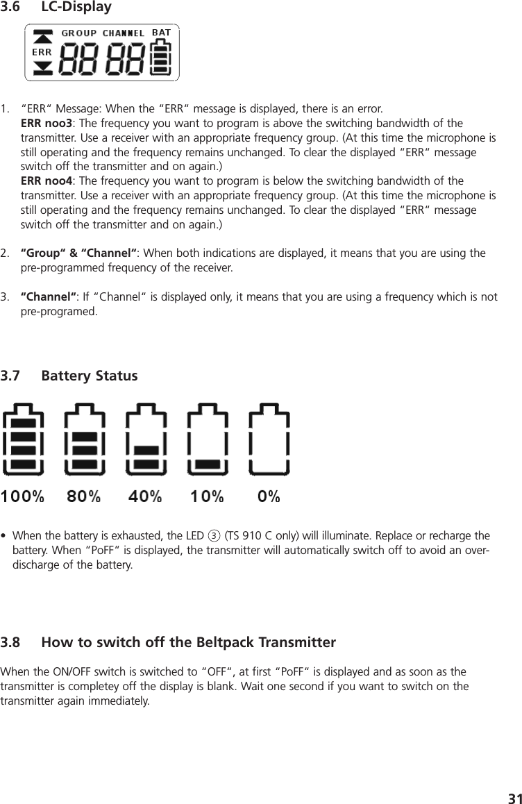
Beyerdynamic Bodypack transmitter Opus910 BA USA A1

User Manual

OPERATING INSTRUCTIONSOpus 910Wireless UHF System
3CONTENTS OPERATING INSTRUCTIONS Opus 910Important Safety Information . . . . . . . . . . . . . . . . . . . Page 4NE 911 / 912 / 914 Diversity Receiver . . . . . . . . . . . . . Page 8ZAS 900 Antenna Splitter . . . . . . . . . . . . . . . . . . . . . . Page 16Connection to a PC . . . . . . . . . . . . . . . . . . . . . . . . . . Page 18S 910 C / S 910 M Handheld Transmitters . . . . . . . . . Page 19TS 910 Beltpack Transmitter . . . . . . . . . . . . . . . . . . . . Page 26General Instructions for all Transmitters . . . . . . . . . . . Page 32Trouble Shooting. . . . . . . . . . . . . . . . . . . . . . . . . . . . . Page 33Maintenance. . . . . . . . . . . . . . . . . . . . . . . . . . . . . . . . Page 34Licensing. . . . . . . . . . . . . . . . . . . . . . . . . . . . . . . . . . . Page 34Components. . . . . . . . . . . . . . . . . . . . . . . . . . . . . . . . Page 34Optional Accessories . . . . . . . . . . . . . . . . . . . . . . . . . . Page 35Technical Specifications . . . . . . . . . . . . . . . . . . . . . . . . Page 36
4OPERATING INSTRUCTIONS OPUS 910Thank you for selecting the Opus 910 wireless system. Please take some time to read carefullythrough this manual before setting up the equipment.Important:• When you unpack the product, inspect it for transport damage. If you do find transport damage,notify the transportation company without delay. Delay in reporting transport damage could resultin the loss of your rights to compensation.Receiver• READ these instructions. • KEEP these instructions.• HEED all warnings.• Follow all instructions.• Do not use this apparatus near water.• Clean only with a dry cloth.• Do not block any ventilation openings. Install in accordance with the manufacturer’s instructions.• Do not install near any heat sources such as radiators, heat registers, stoves or other apparatus(including amplifiers) that produce heat.• Do not defeat the safety purpose of the polarised or grounding-type plug. A polarised plug hastwo blades with one wider than the other. A grounding type plug has two blades and a thirdgrounding prong. The wide blade or the third prong are provided for your safety. If the providedplug does not fit into your outlet, consult an electrician for replacement of the obsolete outlet.• Protect the power cord from being walked on or pinched particularly at plugs, convenience receptacles, and the point where they exit from the apparatus.• Only use attachements/accessories specified by the manufacturer.• Use only with the cart, stand, tripod, bracket or table specified by the manufacturer or sold withthe apparatus. When a cart is used, use caution when moving the cart/apparatus combination toavoid injury from tip-over.• Unplug this apparatus during lightning storms or when unused for long periods of time.• Refer all servicing to qualified service personnel. Servicing is required when the apparatus has beendamaged in any way, such as power-supply cord or plug is damaged, liquid has been spilled orobjects have fallen into the apparatus, the apparatus has been exposed to rain or moisture, doesnot operate normally, or has been dropped.• The equipment must be set up so that the mains switch, mains plug and all connection on the rearof the device are easily accessible. • The equipment must be connected to a mains socket that has an earth contact. • Never expose the equipment to rain or a high level of humidity. For this reason do not install it inthe immediate vicinity of swimming pools, showers, damp basement rooms or other areas withunusually high atmospheric humidity. • Do not use the device/s outside. WARNING: To reduce the risk of fire or electric shock, do notexpose this/these device/s to rain or moisture.• Never place objects containing liquid (e.g. vases or drinking glasses) on the equipment. Liquids inthe equipment could cause a short circuit. • Lay all connection cables so that they do not present a trip hazard. • Check whether the connection figures comply with the existing mains supply. Serious damagecould occur due to connecting the system to the wrong power supply. An incorrect mains voltagecould damage the equipment or cause an electric shock.Important Safety Instructions
5Transmitter• Protect the transmitter from moisture and sudden impacts. You could either injure yourself or othersor damage the transmitter. • Do not blow into the microphone. In a condenser microphone this could damage the transformer.It is preferable to carry out a speech trial. • Clip-on microphones are often very compact. If they are accidentally swallowed there is a risk ofchoking. Always keep this type of microphone away from small children. • Always switch off the transmitter before charging or changing the battery. • If the transmitter is fitted with a normal battery, never charge it in the charging unit. The transmitteror the batteries could be destroyed. There is a risk of explosion. • The normal commercial 9 V alkaline batteries can have a length tolerance of 2 - 3 mm. Whenchanging the battery always ensure good contact. • From time to time the battery contacts should be cleaned with a soft cloth moistened with spiritsor alcohol. • If the transmitter is not being used for weeks or months, please remove the batteries. Batteries canleak when not being used for a long time and corrode the conductor strips and components.Repair is not then possible. In this case all warranty claims are null and void. The description “leakproof” on batteries is no guarantee that they will not run out. • Never take batteries apart yourself. The battery acid contained will damage skin and clothing. • Do not throw used batteries into the domestic rubbish, but hand them in to local collection points.• This equipment needs adequate ventilation. Do not cover ventilation grilles. If the heat it generatescannot be dissipated, the equipment could be damaged or flammable materials in its immediatevicinity could be ignited. Take care to ensure that the air can circulate freely through the ventilationgrilles and keep flammable materials away. • Never place naked flames near the equipment. • If the equipment causes a blown fuse or a short circuit, disconnect it from the mains and have itchecked and repaired. • Do not open the equipment without authorisation. You could receive an electric shock. Leave allservice work to authorised expert personnel. • Do not hold the mains cable with wet hands. There must be no water or dust on the contact pins.In both cases you could receive an electric shock. • The mains cable must be firmly connected. If it is loose there is a fire hazard. • Always pull out the mains cable from the mains and/or from the equipment by the plug - never bythe cable. The cable could be damaged and cause an electric shock or fire. • If the power cable is connected, avoid contact of the unit with other metallic objects. • Do not insert objects into the ventilation grilles or other openings. You could damage the equipment and/or injure yourself. • Do not use the equipment if the mains plug is damaged. • When installing the device into a 19" rack, make sure that the mains switch, mains plug and allconnection on the rear of the device are easily accessible.• When connecting a headphone, please make sure that the volume is turned down to minimum.Adjust the volume after putting on the headphone. Do not set the volume too high, as you couldpermanently damage your hearing.
6FCC RegulationFCC ID:   OSDTS910 for TS 910 M, TS 910 COSDS910M for S 910 MOSDS910C for S 910 CCanada IC:  3628A-S910M for S 910 M3628A-S910C for S 910 C3628A-TS910 for TS 910 M, TS 910 C3628A-NE91X for NE 9113628A-NE91X for NE 9123628A-NE91X for NE 914NOTE: This equipment has been tested and found to comply with the limits for a Class B digitaldevice, pursuant to Part 15 of the FCC Rules. These limits are designed to provide reasonable protection against harmful interference in a residential installation. This equipment generates, usesand can radiate radio frequency energy and, if not installed and used in accordance with the instructions, may cause harmful interference to radio communications. However, there is no guarantee that interference will not occur in a particular installation. If this equipment does causeharmful interference to radio or television reception, which can be determined by turning the equipment off and on, the user is encouraged to try to correct the interference by one or more ofthe following measures:• Reorient or relocate the receiving antenna.• Increase the separation between the equipment and receiver.• Connect the equipment into an outlet on a circuit different from that to which the receiver is connected.• Consult the dealer or an experienced radio/TV technician for help.NOTICE:Changes or modifications made to this equipment not expressly approved by beyerdynamic GmbH & Co. KG may void the FCC authorization to operate this equipment.NOTICE:This device complies with Part 15 of the FCC Rules and with RSS-210 of Industry Canada.Operation is subject to the following two conditions:(1) this device may not cause harmful interference, and(2) this device must accept any interference received, including interference that may cause undesired operation.NOTICE:This Class B digital apparatus complies with Canadian ICES-003.Cet appareil numérique de la classe B est conforme à la norme NMB-003 du Canada. For USA:OPERATION OF WIRELESS MICROPHONES IN THE 700 MHZ BAND IS PROHIBITED AFTER JUNE 12, 2010.
7CONSUMER ALERTMost users do not need a license to operate this wireless microphone system. Nevertheless, operatingthis microphone system without a license is subject to certain restrictions: the system may not causeharmful interference; it must operate at a low power level (not in excess of 50 milliwatts); and it hasno protection from interference received from any other device. Purchasers should also be aware that FCC is currently evaluating use of wireless microphone systems,and these rules are subject to change. For more information, call the FCC at 1-888-CALL-FCC (TTY: 1-888-TELL-FCC) or visit the FCC´s wire-less microphone website at www.fcc.gov/cgb/wirelessmicrophones.
81. NE 900 Diversity Receiver1.1 Controls and IndicatorsNE 911 front viewPower switch with LED indicatorHeadphone inputVolume control for headphone input to listen to individual receiving channelsNE 912 / 914: Press the volume control to select the receiving channelDisplayACT buttonScan buttonMenu control (for selecting different settings)ESC buttonAntenna connection when connecting the antennae on the front123456789NE 912 front viewNE 914 front view1 2 5 4 6 7 83331 2 5 4 6 7 8 991 2 5 4 6 7 8 99
9Antenna input B. TNC socket. With power supply for antenna amplifier. AF output, 3-pin XLR, balancedRemote connection IN / OUTAntenna input A. TNC socket. With power supply for antenna amplifier.MainsNE 911 only: AF output, 1/4" (6.35 mm) jack, unbalancedNE 912 rear viewNE 911 rear viewNE 914 rear view11121314151010 11 15 12 14 1310 11 11 12 141310 11 11 11 11 12 1413
101.2 How to connect the AntennaeConnect the antennae to the TNC sockets      and   ( . Set them at an angle (60°).Please note that for diversity operation both antennae have to be connected. A weighting circuitsilently switches the signal with the better S/N ratio to the output.1.4 LC-Display and Menu SettingsOn the LC-Display all operating parameters such as RF and AF level will be shown. Using the “Menu“control      you can select from 6 options. The selected function is surrounded by a square frame andshown at the bottom of the LC-Display. By selecting the ESC button      you can cancel the current entry into the menu to display the previous setting.To select the individual receiving channels of the NE 912 / 914 for entering the menu settings, pressthe menu control      until the green LED between the ACT and the SCAN button is flashing. Turn themenu control to select the receiving channel. The green LED of the selected receiving channel willflash. Press the menu control to confirm. The green LED will illuminate permanently.The functions and operation are described in the following.1.3 Setting up1. Place the diversity receiver in the same room or area as the transmitters. Make sure the diversityreceiver is placed as close as possible to the transmitter. 2. Do not place the diversity receiver near digitally controlled equipment.3. Connect the AF-output to the corresponding input of the mixing console or amplifier.4. Connect the receiver to AC power.5. Switch on the receiver     . The red LED will illuminate.6. If you use the receiver on a tabletop, please stick the supplied rubber pads to the bottom of thereceiver to ensure a sufficient ventilation.131011.4.1 Diversity indication of the Receiving ChannelEach receiving module has two separate receiving circuits, one for each antenna. The signal with thebetter S/N ratio is switched to the output. The received diversity channel  is shown in the LC-display.778
111.4.2 How to read the AF and RF levelThe AF or RF level is shown in the LC-display.1.4.3 Group, Channel• Turn the menu control      to select “G/CH”. The currently selected group and channel are displayed.• To change the setting, press the menu control. The group number will start flashing. Turn themenu control to select the desired group. In order to confirm the selected group press the menucontrol.• At the same time the channel number will start flashing. Turn the menu control to select the desired channel. In order to confirm the selected channel press the menu control. • Press the Scan button to select a channel automatically. Press the Scan button once again and thereceiver will adjust an interference-free channel automatically within the selected group. Press themenu control to confirm the selected channel. 1.4.4 Frequency• Turn the menu control      to select “FREQ”. The currently selected frequency is displayed. • To change the setting press the menu control. The first three digits (MHz) will start flashing. Turnthe menu control to select the desired value. The first three digits of the frequency (MHz) can beselected in steps of 1 MHz. In order to confirm press the menu control. • At the same time the last three digits (kHz) will start flashing. Turn the menu control to select thedesired value. The last three digits (kHz) can be selected in steps of 25 kHz.• In order to confirm press the menu control. 77
121.4.5 Squelch• Turn the menu control      to select “SQ”. The currently selected squelch is displayed.• To change the squelch level, press the menu control. The squelch level will start to flash. Turn themenu control to select the desired squelch level between 1 and 99. In order to confirm theselected squelch level, press the menu control.1.4.6 Output Level / Mute• Turn the menu control      to select “VOL”. Now you can check the output level or if the receiver ismuted. • To change the setting, press the menu control. The current setting will start to flash. • Turn the menu control to mute the receiver or to set the output level according to the transmittergain (0 dB, -10 dB, -20 dB, -30 dB). • Press the menu control to confirm the setting. 77
131.4.7 Name• Turn the menu control      to select “NAME”. A stored name is displayed or you can enter a newname.• To enter a new name press the menu control. The first digit will start to flash. Turn the menu control to select the desired letter, number or character. • In order to confirm and to enter the second digit, press the menu control. Repeat these steps toenter all desired characters, letters or numbers. You can enter a maximum of 6 digits, symbols orletters.1.4.8 Addressing / Control via PC• Turn the menu control      to select “REMO”. The address and the status of the remotely controlledchannel is displayed. • To ensure a smooth control via PC, the receiving channels have to be addressed differently beforeusing the software. IMPORTANT:Each channel must have its own address. If two or more channels have the same address, errorswill occur. If the receivers are operated without a PC, it does not matter if two or more receivershave the same address.• When the receiver is PC-controlled “ON“ and a number are displayed. This number is the addressof the appropriate channel. • When the receiver is operated without PC “OFF“ and the address are displayed.• If you want to adjust or change the address, press the menu control. The number will start toflash. Turn the menu control to select the desired address. In order to confirm the selected address,press the menu control.77
141.4.9 Lock FunctionThe receivers have a lock function to avoid the setting of the receiver configuration to be changedinadvertently.How to activate the “Lock” Function• Press the ACT and Scan buttons simultaneously.• A red padlocked symbol is displayed.• Now all buttons, except the ACT button are locked.• By turning the menu control the current receiving channel configuration can still be displayed.• The “Lock” function is still activated when the receiver is switched off and on again.How to deactivate the “Lock” Function• Press the ACT and Scan buttons simultaneously. The red padlocked symbol will disappear.1.5 Frequency Transmission to Transmitter (ACT Function)• The frequency of the receiver is transmitted to the appropriate transmitter via infrared.• Press the ACT button to activate the ACT function. “ACT” is displayed.• Hold the infrared diode of the switched on transmitter 20 cm at maximum in front of the transmitting infrared diode of the receiver between the ACT and Scan button.• The receiver displays “ACT” during the transmission.• As soon as the transmitter displays the same frequency as the receiver, the transmission is finished.The receiver displays the state before starting the frequency transmission.Important:In order to avoid interferences, the frequency of one receiver should be transmitted to one transmitteronly.NE 911 NE 912 / 914Infrared diode Infrared diode
151.6 Connecting and Positioning of remote AntennaeIn multichannel systems we recommend the use of the AT 70 A/B UHF antenna set consisting ofantennae, cables, antenna boosters and mounting kit.1. Connect the receiving antennae to the corresponding antenna inputs and place the antennae tothe right and left of the receiver in the operating range where the transmitter is to be used. Ifnecessary change the position of the antennae to improve diversity reception.2. The distance between the two receiving antennae should be at least 1 m.3. The distance between transmitting and receiving antennae should be at least 3 m to avoid overloading and interference between different channels. We therefore recommend installing theantennae in a high position, especially in multi-channel systems.4. If the operating range of the transmitters isgreater than the stage, the antennae canbe mounted vertically on the ceiling. The distance between the two receiving antennae should be approximately half thetotal operating range.Please note:1. Install the receiving antennae in the same area as the transmitter.2. To avoid interference do not install the antennae near digitally controlled components.3. Keep a minimum distance of 0.5 m from metallic objects, including reinforced concrete walls orpillars.4. Do not bend the antenna cables at the antenna input, and ensure that they are not subjected toundue stress.> 1 m> 3 m> 1 mABStageAuditoriumOperating rangeStage
161.7 ZAS 900 Antenna Splitter1.7.1 Controls and Indicators(1) On/Off switch and power on LED. When the antenna splitter is switched on, the redLED will illuminate.(2) RF outputs to connect the receivers(3) DC-connection to connect the DC power supply unit (12 V)(4) Antenna sockets A/B. The antenna sockets provide a DC supply for antenna amplifiers. (DC-Out: 8 V / 170 mA)(5) Mounting brackets for 19" rack mounting1.7.2 Installation1. Mount the ZAS 900 antenna splitter and the receivers into a 19" rack by using the mountingbrackets.2. Connect the supplied antennae to the antenna sockets A/B (4). You can also use optional remoteantennae. For mounting the antennae on the front use the supplied FB-30 mounting bracket.3. Connect the receivers to the ZAS 900 antenna splitter with the supplied cables.4. Connect the power supply unit to the DC-connection (3) and to AC power. (Attention: Make sure that the indicated voltage corresponds to the local voltage.)5. Switch on the ZAS 900 antenna splitter (1).First receiverSecond receiverThird receiverFourth receiver
171.7.3 General Information1. The antenna sockets (4) feature a voltage of 8 V DC bias. To avoid a short circuit the socketsmust not touch the rack housing.2. For the connection of remote antennae use usual 50Ω coaxial cables. The longer the cable, thehigher the RF signal loss. Therefore, the cable length should not exceed 6 m.If you use longer cables, please use low-attenuation cables and if necessary antenna amplifiers.3. Use 50Ω coaxial cables to connect the receivers to the ZAS 900 antenna splitter. The distancebetween these devices should be as short as possible. We recommend using the supplied cables.4. Supplied Accessories:8 x RG 58 AU cables, 40 cm (TNC)1 pair rack mount brackets supplied with antenna cables for front mounting1 x 12 V / 500 mA power supply unit
181.8 Connection to a PCThe NE 911/912/914 receiver is fitted with an RJ 11 connector      with an IN and OUT socket. Inorder to operate several receivers with a PC they have to be connected as described below. • Connect the OUT-socket of the first receiver (RX 1) with the IN-socket of the second receiver (RX 2),connect the OUT-socket of the second receiver (RX 2) with the IN-socket of the third receiver (RX 3)and so on.• Connect the IN-socket of the first receiver (RX 1) to the converter.• Connect the converter to the USB interface of the PC.• By using the PC control software, 64 channels can be operated simultaneously at maximum. • The distance between PC and receiver should not be too long, because to ensure high-speed transmission the remote control cable should not be longer than 100 metres.12USB PORTRJ 11
192. S 910 C / S 910 M Handheld Transmitter2.1 Controls and IndicatorsThere are different condenser and dynamic microphone capsules for the handheld transmitter (refer to Optional Accessories). The S 910 C handheld transmitter has charging contacts and can be operated with the integratedrechargeable battery pack only. For charging, the SLG 900 charger is available. Avoid a direct contact of the charging contacts to the skin, as there is a voltage of 3 V at maximum.Microphone capsule (can be unscrewed)LC-DisplayInfrared diode (at the bottom of the transmitter)On/Off switch (at the bottom of the transmitter)Charging contacts (at the bottom of the transmitter S 910 C only )S 910 M Microphone capsule (can be unscrewed)LC-DisplayInfrared diode (on the rear)On/Off switch 123412345S 910 C1 2 3451 2 43
202.2 How to insert the Batteries (S 910 M)1. Unscrew the shaft of the S 910 M counter-clockwise.2. Insert two 1.5 V batteries into the battery compartment observing polarity markings.Note:The S 910 C transmitter is powered by rechargeable batteries which cannot be changed by the user. Ifthe rechargeable batteries have to be changed, please contact your beyerdynamic dealer.2.3 LC-Display1. “ERR“ Message: When the “ERR“ message is displayed, there is an error.ERR noo3: The frequency you want to program is above the switching bandwidth of the transmitter. Use a receiver with an appropriate frequency group. (At this time the microphone isstill operating and the frequency remains unchanged. To clear the displayed “ERR“ messageswitch off the handheld transmitter and on again.)ERR noo4: The frequency you want to program is below the switching bandwidth of the transmitter. Use a receiver with an appropriate frequency group. (At this time the microphone isstill operating and the frequency remains unchanged. To clear the displayed “ERR“ messageswitch off the handheld transmitter and on again.)2. “Group“ & “Channel“: When both indications are displayed, it means that you are using thepre-programmed frequency of the receiver.3. “Channel“: If “Channel“ is displayed only, it means that you are using a frequency which is notpre-programed.
212.4 Battery Status• When the battery is exhausted, the LED at the bottom of the handheld transmitter will illuminate.Replace the battery. When “PoFF“ is displayed, the transmitter is switched off, if the battery voltage is too low.2.5 How to switch off the Handheld TransmitterWhen the ON/OFF switch at the bottom of the transmitter is switched to “OFF“, at first “PoFF“ is displayed and as soon as the transmitter is completey off the display is blank. Wait one second if youwant to switch on the transmitter again immediately.2.6 How to change the Microphone CapsuleThere are different microphone capsules available for the handheld transmitter. If you want to changethe microphone capsule, turn it anti-clockwise to unscrew it from the transmitter. Put the selectedmicrophone capsule onto the transmitter and turn it clockwise to tighten. CM 930Cardioid condenser microphone capsule for vocals and speech applications. For maximum gain before feedback. Weight 191 g.DM 960Hypercardioid dynamic microphone capsule. Suitable for vocals and broad-casting applications. Weight 191 g.
22DM 969Supercardioid dynamic microphone capsule. Suitable for vocals.Weight 131 g.EM 981Cardioid electret condenser microphone capsule for solo vocals, conferences and speech. Weight 191 g.RM 510Cardioid dynamic ribbon microphone head.Weight 165 g.
232.7 Maintenance• Protect the handheld transmitter from humidity, knocks and shock. Avoid dropping the transmitterat all times.• For cleaning metal surfaces, use a soft cloth moistened with methylated spirits or alcohol.• As soon as your microphone sounds dull, you should clean the integrated pop shield. Proceed asdescribed in the following.CM 930• Unscrew the microphone capsule (turn anti-clockwise). • Unscrew the wire mesh pop shield (turn anti-clockwise). • Clean the pop shield under clear running water. • Allow the pop shield to dry overnight before you replace it.• The wire mesh pop shield cannot be cleaned in a dishwasher. DM 960• Unscrew the upper part of the microphone basket (turn anti-clockwise).• Clean it under clear water.• Let the pop shield dry overnight before you replace it.• The upper part of the microphone basket cannot be cleaned in a dishwasher.
24EM 981• Unscrew the microphone capsule (turn anti-clockwise). • Unscrew the wire mesh pop shield (turn anti-clockwise). • Clean the pop shield under clear running water. • Allow the pop shield to dry overnight before you replace it.• The wire mesh pop shield cannot be cleaned in a dishwasher. DM 969• Unscrew the upper part of the microphone basket (turn anti-clockwise).• Pull out the foam pop shield and clean it under clear running water.• If necessary, use a mild washing-up liquid. • Dry it afterwards with a hairdryer or allow it to dry overnight.• Place the dry pop shield inside the microphone basket and replace themicrophone basket by screwing it on clockwise.RM 510• Loosen the screws. • Unscrew the upper part of the microphone head (turn anti-clockwise). • Clean the upper basket under clear running water.• Allow the upper basket to dry overnight before you replace it.• The upper basket cannot be cleaned in a dishwasher.
252.8 How to adjust the Gain• To adjust the gain unscrew the complete microphone head with the upper shaft as indicated by thearrows.• Use a screwdriver to select the gain (0 dB, 10 dB, 20 dB, 30 dB).• Lowest gain = 0 dBHighest gain = 30 dBUnscrew microphone head Select gain2.9 How to set the Low-cut Filter• The CM 930 and EM 981 microphone capsules feature a low-cut filter to compensate the close-miking effect which ususally occurs with directional microphones. To set the low-cut filter unscrewthe complete microphone head with the upper shaft as indicated by the arrows. • At the bottom of the microphone head you can set the low-cut filter. •Standard setting: linear (position Lin)Unscrew microphone head Set low-cut filter
263. TS 910 Beltpack TransmitterThe TS 910 C beltpack transmitter provides charging contacts and can be powered by the optionalbeyerdynamic TS 900 AP rechargeable battery pack. For charging, the SLG 900 charger is available.With this charger the TS 900 AP battery pack inside the TS 910 C beltpack transmitter can be recharged only, no standard rechargeable batteries.3.1 Controls and IndicatorsAF input, 4-pin mini XLR for microphones (lavalier, neckworn mics). For connection please refer to chapter 3.5 “AF Connection”. ON/OFF switch (ON = switch to “ON“-position; OFF = switch to “OFF“ position).Switch off the transmitter when not in use.TS 910 C only: Battery status LED to indicate the power on / off and battery status.(a) When the beltpack transmitter is switched on this LED will flash for a moment toindicate the normal battery status.(b) When the LED stays red after having switched on the transmitter the battery is to weak andmust be replaced.Transmitting antennaLC-DisplayInfrared receiving diode for ACT function.Gain control to adjust input gain.GT/MT switch: When you use electric guitars this switch must be in the “GT“ position. In the GT mode the gain control is deactivated. Switch to the “MT“ position when youuse condenser and wired microphones. In the MT mode the gain control is activated.Battery compartment and cover for two 1.5 V batteries (AA) or TS 900 AP rechargeable battery pack.TS 910 C only: Charging contacts for TS 900 AP battery pack only (not supplied).Removable belt clip can be rotated 360°. To remove use a screwdriver at a 45° angle.1234567891011TS 910 C1523467891011TS 910 C
27AF input, 4-pin mini XLR for microphones (lavalier, neckworn mics). For connection please refer to chapter 3.5 “AF Connection”.ON/OFF switch (ON = switch to “ON“-position; OFF = switch to “OFF“ position).Switch off the transmitter when not in use.Transmitting antennaLC-DisplayInfrared receiving diode for ACT function.Gain control to adjust input gain.GT/MT switch: When you use electric guitars this switch must be in the “GT“ position. In the GT mode the gain control is deactivated. Switch to the “MT“ position when youuse condenser and wired microphones. In the MT mode the gain control is activatedBattery compartment and cover for two 1.5 V batteries (AA).Removable belt clip can be rotated 360°. To remove use a screwdriver at a 45° angle.TS 910 M12456789111245678119TS 910 M
28This is how to remove the belt clip3.2 How to insert the Batteries / rechargeable Battery Pack1. Push down the two snap locks on the right and left of the battery compartment and open it.Remove the batteries. Refer to Fig. 1.2. Insert two 1.5 V batteries into the battery compartment observing polarity markings. Refer to Fig. 2. The battery pack is secured mechanically against confusing the poles. Then close the batterycompartment again.Fig. 1 Fig. 2Fig. 1 Fig. 2TS 910 M: Insert batteriesTS 910 C: Insert rechargeable battery pack
293.3 Setting up1. Push down the two snap locks on the right and left of the battery compartment and open it.Now you can adjust the GT/MT switch      and the gain control     .2. Make sure that the transmitter and receiver are on the same frequency.3. The LED of the TS 910 C will flash for a moment when the transmitter is switched on and indicates the normal battery status. When the LED fails to flash, there is no battery inserted, thebattery is leaking or inserted incorrectly. The battery status of the TS 910 M can be seen in theLC-Display.4. Connect the microphone or instrument to the input socket     . Refer to illustration below.8713.4 Adjusting the Input Gain1. Switch on the TS 910 beltpack transmitter with the ON/OFF switch     . Turn the gain controlfully anti-clockwise to minimum gain.2. Speak into the microphone at the maximum level you expect to use. We recommend you use theletter “U” as a spoken “U” has a relatively good sine wave shape. Adjust the gain control      tothe desired gain. On the NE 911/912/914 receiver the AF level must not show any clipping. Whenmiking instruments, play at the maximum level you expect to use.277
303.5 AF Connection(1) 2-Wire Electret Condenser Microphone Capsule(2) 3-Wire Electret Condenser Microphone Capsule(3) Dynamic Microphone(4) Electric Guitar(5) Line-in (impedance 8Ω, attenuation 10 dB)e.g. Opus 54.18, Opus 55.18, Opus 56.18, MCE 7.18e.g. MCE 5.18, MCE 10.18, MCE 60.18
313.6 LC-Display1. “ERR“ Message: When the “ERR“ message is displayed, there is an error.ERR noo3: The frequency you want to program is above the switching bandwidth of the transmitter. Use a receiver with an appropriate frequency group. (At this time the microphone isstill operating and the frequency remains unchanged. To clear the displayed “ERR“ messageswitch off the transmitter and on again.)ERR noo4: The frequency you want to program is below the switching bandwidth of the transmitter. Use a receiver with an appropriate frequency group. (At this time the microphone isstill operating and the frequency remains unchanged. To clear the displayed “ERR“ messageswitch off the transmitter and on again.)2. “Group“ & “Channel“: When both indications are displayed, it means that you are using thepre-programmed frequency of the receiver.3. “Channel“: If “Channel“ is displayed only, it means that you are using a frequency which is notpre-programed. 3.7 Battery Status• When the battery is exhausted, the LED      (TS 910 C only) will illuminate. Replace or recharge thebattery. When “PoFF“ is displayed, the transmitter will automatically switch off to avoid an over-discharge of the battery.3.8 How to switch off the Beltpack TransmitterWhen the ON/OFF switch is switched to “OFF“, at first “PoFF“ is displayed and as soon as the transmitter is completey off the display is blank. Wait one second if you want to switch on the transmitter again immediately.3
324. General Instructions for all Transmitters4.1 Battery Change• Switch the transmitter off before changing the battery.• If you do not use the transmitter for several weeks or months, please remove the battery as it canleak after some time and damage parts of the transmitter. Even “leak proof” may leak after sometime. Damage caused by leaking batteries is not covered under warranty.• Clean the battery contacts from time to time by using a soft cloth moistened with spirits or alcohol.• Please do not throw used battery packs away with your household rubbish, but take them to yourlocal collection points.• When using the S 910 C handheld transmitter or TS 910 C beltpack transmitter (fitted with TS 900 APrechargeable battery pack) use the beyerdynamic SLG 900 charger only.4.2 Before the Soundcheck1. Check the transmitter battery and replace or recharge it if necessary. Use fresh alkaline batteriesonly or recharge the rechargeable batteries inside the S 910 C handheld transmitter or TS 910 Cbeltpack transmitter (fitted with TS 900 AP).2. When the transmitter is switched off and immediately switched on again, it is possible that thetransmitter remains switched off. The cause is the function that allows to switch the transmitteron / off silently. Should this problem occur during operation, the battery might have contact problems. After switching off the transmitter you should wait at least 1 second, until you switchthe transmitter on again.3. Check the performance area for dropouts. If you find any dropouts, try to eliminate them byrepositioning the antennae or the receiver.4. The receiving antennas should be placed so that the distance between receiving antennae andtransmitter is at least 3 m. If necessary, use remote antennae (AT 70 A/B). 4.3 Positioning of Transmitters if Interference occursPut all transmitters in their position and switch them on. Switch each transmitter off one at a timeand check the receiver for interference in the corresponding channel. The interference is possibly eliminated by changing the squelch (refer also to chapter 1.4.5 “Squelch”.When using multi-channel-systems, please contact beyerdynamic. Interferences can also be caused byDVB-T television transmitters in the neighbourhood.4.4 What to Do to avoid FeedbackFeedback is caused by your microphone getting too close to a loudspeaker.We recommend:• Move away from the loudspeaker.• Turn the microphone away from the loudspeaker.
335. Trouble Shooting5.1 NE 911/912/914 Diversity Receiver5.2 Handheld and Beltpack Transmitter•Power supply is interrupted, power supply unit is not connected to the mains and / or to receiver• Connect the receiver to AC power•Switch on the transmitter• Adjust the correct frequency with theACT function• Check the antenna cables•Input amplifier of the connected mixer isoverloaded• Use the gain control of the mixer or adjust the volumeDistorted soundNo receptionNo functionProblem Possible Cause Solution• Transmitter is not switched on• Transmitter works on a different channel• Defect in the antenna cables with remote antennae“CLIP” indication onreceiver•Transmitter is overloaded• Reduce the sensitivity of the transmitter or increase the distance between microphone and sound source.No sound, RF-indication isokay, AF- indication ismissing during modulation•Wrong indication caused by strong interference signals• No microphone connected to TS 910 beltpack transmitter• Choose another receiving channel• Connect a suitable microphone• Transmitter and receiver have different frequencies• Insufficient battery voltage• Poor battery contact, battery inserted incorrectly• Check if transmitter and receiver have the same frequency• Replace the batteries or recharge them, if you use rechargeable batteries• Check the battery and insert it again•Transmission distance between transmitterand receiver is too big• Reduce the distance between transmitter and receiverNo RF-indication at thereceiver•Interference from other transmitters• Two transmitters are on the same frequency• Battery of the transmitter is too weak• Switch off the other transmitters• Change the frequency of one transmitter• Replace the batteriesNoise/chirpingNo functionProblem Possible Cause Solution
346. MaintenanceIn the unlikely event of equipment failure, the product should be returned to your beyerdynamic dealer. Unauthorised attempts at repair may invalidate the warranty.7. Licensing In most countries around the world, wireless systems must be approved for use by the authorities andit may be necessary to obtain a licence to use it legally. Your local beyerdynamic dealer will be able togive you details on wireless system regulations for your area.The components of the Opus 910 system are approved according to the directive 99/5/EEC:TS 910 M, TS 910 CS 910 M, S 910 C under the CE 0682  !  identification.8. ComponentsReceiverNE 911 1-channel true diversity receiver, 482 – 554 MHz (US). . . . . . . . Order # 705.004same as above, but 554 – 626 MHz (US) . . . . . . . . . . . . . . . . . Order # 705.012same as above, but 626 – 698 MHz (US) . . . . . . . . . . . . . . . . . Order # 705.020NE 912 2-channel true diversity receiver, 482 - 554MHz (US) . . . . . . . . Order # 705.071same as above, but 554 – 626 MHz (US) . . . . . . . . . . . . . . . . . Order # 705.098same as above, but 626 – 698 MHz (US) . . . . . . . . . . . . . . . . . Order # 705.101NE 914 4-channel true diversity receiver, 482 – 554 MHz (US). . . . . . . . Order # 705.160same as above, but 554 – 626 MHz (US) . . . . . . . . . . . . . . . . . Order # 705.179same as above, but 626 – 698 MHz (US) . . . . . . . . . . . . . . . . . Order # 705.187Handheld TransmitterS 910 M UHF handheld transmitter, metal housing, black, 482 – 518 MHz (US) . . . . . . . . . . . . . . . . . . . . . . . . . . . . . . . . . Order # 705.233same as above, but 518 – 554 MHz (US) . . . . . . . . . . . . . . . . . Order # 705.241same as above, but 554 – 590 MHz (US) . . . . . . . . . . . . . . . . . Order # 705.268same as above, but 590 – 626 MHz (US) . . . . . . . . . . . . . . . . . Order # 705.276same as above, but 626 – 662 MHz (US) . . . . . . . . . . . . . . . . . Order # 705.284same as above, but 662 – 698 MHz (US) . . . . . . . . . . . . . . . . . Order # 705.292
35S 910 C UHF handheld transmitter, plastic housing, black, with charging contacts, 482 – 518 MHz (US) . . . . . . . . . . . . . . Order # 705.381same as above, but 518 – 554 MHz (US) . . . . . . . . . . . . . . . . . Order # 705.403same as above, but 554 – 590 MHz (US) . . . . . . . . . . . . . . . . . Order # 705.411same as above, but 590 – 626 MHz (US) . . . . . . . . . . . . . . . . . Order # 705.438same as above, but 626 – 662 MHz (US) . . . . . . . . . . . . . . . . . Order # 705.446same as above, but 662 – 698 MHz (US) . . . . . . . . . . . . . . . . . Order # 705.454Beltpack TransmitterTS 910 M UHF beltpack transmitter, metal housing, 482 – 518 MHz (US) . . . Order # 705.691same as above, but 518 – 554 MHz (US) . . . . . . . . . . . . . . . . . Order # 705.705same as above, but 554 – 590 MHz (US) . . . . . . . . . . . . . . . . . Order # 705.713same as above, but 590 – 626 MHz (US) . . . . . . . . . . . . . . . . . Order # 705.721same as above, but 626 – 662 MHz (US) . . . . . . . . . . . . . . . . . Order # 705.748same as above, but 662 – 698 MHz (US) . . . . . . . . . . . . . . . . . Order # 705.756TS 910 C UHF beltpack transmitter, plastic housing, with charging contacts, 482 – 518 MHz (US) . . . . . . . . . . . . . . Order # 705543same as above, but 518 – 554 MHz (US) . . . . . . . . . . . . . . . . . Order # 705.551same as above, but 554 – 590 MHz (US) . . . . . . . . . . . . . . . . . Order # 705.578same as above, but 590 – 626 MHz (US) . . . . . . . . . . . . . . . . . Order # 705.586same as above, but 626 – 662 MHz (US) . . . . . . . . . . . . . . . . . Order # 705.594same as above, but 662 – 698 MHz (US) . . . . . . . . . . . . . . . . . Order # 705.6089. Optional AccessoriesNE 900 Diversity ReceiverAntenna SplitterZAS 900 UHF antenna splitter, active, 19" housing, incl. cable set, 480 - 800 MHz . . . . . . . . . . . . . . . . . . . . . . . . . Order # 497.541AntennaeAT 70 A/B Set UHF antenna set for NE 911 / 912 / 914, cpl. with2 x AT 70 B TNC booster, 2 x AT 70 TNC antenna and2 x MS 10 mounting kit . . . . . . . . . . . . . . . . . . . . . . . . . . . . . . Order # 459.976FBC 71 Cable rear-to-front for NE 911 / 912 / 914 and ZAS 900 (1 pair) . . . . . . . . . . . . . . . . . . . . . . . . . . . . . . . . . . . . Order # 469.823FB 72 Mounting bracket, metal, for mounting of ZAS 900 into a 19"-rack. . . . . . . . . . . . . . . . . . . . . . . . . . . . . . Order # 469.807Individual Components - SoftwareUSB Adapter Opus 910 USB Adapter. . . . . . . . . . . . . . . . . . . . . . . . . . . . . . . Order # 490.776RJ 11 Cable Opus 910 RJ 11 . . . . . . . . . . . . . . . . . . . . . . . . . . . . . . . . . . . . Order # 490.784CD ROM Opus 910 CD-ROM. . . . . . . . . . . . . . . . . . . . . . . . . . . . . . . . . . Order # 490.792S 900 Handheld TransmitterMicrophone CapsulesCM 930 B Condenser, cardioid, black . . . . . . . . . . . . . . . . . . . . . . . . . . . . Order # 490.539CM 930 S Condenser, cardioid, silver. . . . . . . . . . . . . . . . . . . . . . . . . . . . . Order # 491.721DM 960 B Dynamic, hypercardioid, black. . . . . . . . . . . . . . . . . . . . . . . . . . Order # 490.490DM 960 S Dynamic, hypercardioid, silver . . . . . . . . . . . . . . . . . . . . . . . . . . Order # 490.504
36DM 969 S Dynamic, supercardioid, silver . . . . . . . . . . . . . . . . . . . . . . . . . . Order # 490.512EM 981 S Electret condenser, cardioid, silver. . . . . . . . . . . . . . . . . . . . . . . Order # 490.520RM 510 Ribbon, dynamic, cardioid, silver . . . . . . . . . . . . . . . . . . . . . . . . Order # 703.109TS 900 Beltpack TransmitterMicrophonesMCE 5.18 Condenser clip-on microphone, omnidirectional, black . . . . . . . Order # 471.879MCE 10.18 Condenser clip-on microphone, cardioid, black. . . . . . . . . . . . . Order # 471.895MCE 60.18 Condenser clip-on microphone, omnidirectional, black . . . . . . . Order # 469.548Opus 54.18 Neckworn microphone, cardioid, black . . . . . . . . . . . . . . . . . . . Order # 464.945Opus 55.18 Neckworn microphone, omnidirectional, black . . . . . . . . . . . . . Order # 465.356TG-X 54.18  Neckworn microphone, supercardioid, black . . . . . . . . . . . . . . . Order # 700.061TG-X 55.18 Neckworn microphone, omnidirectional, black . . . . . . . . . . . . . Order # 700.096CableMJ 41 G Cable for instruments with 1/4" jack (6.35 mm),for TS 910 (C / M) beltpack transmitter. . . . . . . . . . . . . . . . . . . Order # 460.087S 900 C Handheld Transmitter and TS 900 Beltpack TransmitterNiMH battery Rechargeable battery, 1.2 V / 2500 mAh for S 910 C . . . . . . . . Order # 903.442TS 900 AP Rechargeable battery pack, NiMH, 2 x 1.5 V (AA) for TS 910 C. . Order # 486.957SLG 900 Charger with two charging compartments for S 910 Cor TS 910 C . . . . . . . . . . . . . . . . . . . . . . . . . . . . . . . . . . . . . . . Order # 485.29210. Technical SpecificationsNE 900 Diversity ReceiverOperating principle. . . . . . . . . . . . . . . . . True diversity receiver (UHF)Frequency range. . . . . . . . . . . . . . . . . . . 482 – 554 MHz (US)554 – 626 MHz (US)626 – 698 MHz (US)Power consumption . . . . . . . . . . . . . . . . NE 911: 10 W NE 912: 15 W NE 914: 25 WPower consumption in stand-by mode . . . NE 911 / 912 / 914: 2.5 WSwitching bandwidth . . . . . . . . . . . . . . . 72 MHzSensitivity . . . . . . . . . . . . . . . . . . . . . . . . 2 µVAntenna connection . . . . . . . . . . . . . . . . 2 x TNCNominal deviation . . . . . . . . . . . . . . . . . ± 40 kHzOutput level . . . . . . . . . . . . . . . . . . . . . . 1.2 VCompander system. . . . . . . . . . . . . . . . . NE572Signal-to-noise ratio . . . . . . . . . . . . . . . . > 110 dB(A)T.H.D. . . . . . . . . . . . . . . . . . . . . . . . . . . . < 0.5% at 1 kHzSquelch . . . . . . . . . . . . . . . . . . . . . . . . . 2 µV - 1 mV, adjustablePower supply . . . . . . . . . . . . . . . . . . . . . 12 V - 15 V DCMains . . . . . . . . . . . . . . . . . . . . . . . . . . . 100 V - 240 V ACDimensions. . . . . . . . . . . . . . . . . . . . . . . NE 911 (L x W x H): 210 x 235 x 43 mmNE 912 / 914 (L x W x H): 482 x 270 x 43 mmWeight . . . . . . . . . . . . . . . . . . . . . . . . . . NE 911: 1.36 kgNE 912: 2.75 kgNE 914: 3.1 kgMinimum distance of the profiles when mounting into a 19" rack . . . . . . . 446 mm
37S 910 (M / C) + CM 930 / DM 960 / DM 969 / RM 510 / EM 981Handheld TransmitterPolar pattern . . . . . . . . . . . . . . . . . . . . . Hypercardioid (S 910 + DM 960)Supercardioid (S 910 + DM 969)Cardioid (S 910 + RM 510, S 901 + EM 981, S 910 + CM 930)Transducer type . . . . . . . . . . . . . . . . . . . True condenser (S 910 + CM 930)Dynamic (S 910 + DM 960, S 910 + DM 969)Ribbon, dynamic (S 910 + RM 510)Electret condenser (S 910 + EM 981)Frequency range. . . . . . . . . . . . . . . . . . . 482 – 518 MHz (US)518 – 554 MHz (US)554 – 590 MHz (US)590 – 626 MHz (US)626 – 662 MHz (US)662 – 698 MHz (US)Modulation . . . . . . . . . . . . . . . . . . . . . . FMNominal deviation . . . . . . . . . . . . . . . . . ± 40 kHzRadiated transmitter power . . . . . . . . . . 10 mWCompander system. . . . . . . . . . . . . . . . . NE572Max. SPL . . . . . . . . . . . . . . . . . . . . . . . . 146 dB AF transmission rangeS 910 + DM 960 . . . . . . . . . . . . . . . . . . . 55 - 18,000 Hz (close miking 2 cm) at 80 dB SPLS 910 + DM 969 65 - 16,000 Hz (close miking 2 cm) at 80 dB SPL S 910 + EM 981 50 - 18,000 Hz (close miking 2 cm) at 80 dB SPL S 910 + CM 930 40 - 20,000 Hz (close miking 2 cm) at 80 dB SPL S 910 + RM 510 70 - 14,000 Hz (close miking 2 cm) at 80 dB SPL  Rear attenuation. . . . . . . . . . . . . . . . . . . -20 dB at 1 kHz / 120° (S 910 + DM 960)-15 dB at 1 kHz / 145° (S 910 + DM 969)-15 dB at 1 kHz / 180° (S 910 + EM 981)-20 dB at 1 kHz / 180° (S 910 + CM 930)-18 dB at 1 kHz (S 910 + RM 510)Signal-to-noise ratio . . . . . . . . . . . . . . . . > 110 dBT.H.D. . . . . . . . . . . . . . . . . . . . . . . . . . . . < 0.5% at 1 kHzTransmission range . . . . . . . . . . . . . . . . . 100 mPower supply . . . . . . . . . . . . . . . . . . . . . 2 x 1.5 V batteries (AA) or rechargeable batteriesCurrent consumption . . . . . . . . . . . . . . . approx. 85 mAOperating time . . . . . . . . . . . . . . . . . . . . > 20 hours with alkaline batteriesDimensionsLength . . . . . . . . . . . . . . . . . . . . . . . . . . . . . S 910 C: 188 mm S 910 M: 210.5 mmShaftø . . . . . . . . . . . . . . . . . . . . . . . . . . S 910 C: 38 mm S 910 M: 38 mmWeight with batteries. . . . . . . . . . . . . . . S 910 C: 169 g S 910 M: 172 g
38TS 910 (C / M) Beltpack TransmitterFrequency range. . . . . . . . . . . . . . . . . . . 482 – 518 MHz (US)518 – 554 MHz (US)554 – 590 MHz (US)590 – 626 MHz (US)626 – 662 MHz (US)662 – 698 MHz (US)Modulation . . . . . . . . . . . . . . . . . . . . . . FMNominal deviation . . . . . . . . . . . . . . . . . ± 40 kHzRadiated transmitter power . . . . . . . . . . 20 mWCompander system. . . . . . . . . . . . . . . . . NE572Signal-to-noise ratio . . . . . . . . . . . . . . . . > 110 dBT.H.D. . . . . . . . . . . . . . . . . . . . . . . . . . . . < 0.5% at 1 kHzFrequency response . . . . . . . . . . . . . . . . 50 Hz - 18,000 HzGain . . . . . . . . . . . . . . . . . . . . . . . . . . . . 10 mV - 0.3 V adjustable, at nominal deviationPower supply . . . . . . . . . . . . . . . . . . . . . 2 x 1.5 V batteries (AA) or rechargeable batteries Current consumption . . . . . . . . . . . . . . . approx. 85 mAOperating time . . . . . . . . . . . . . . . . . . . . > 20 hours with alkaline batteriesDimensions (L x W x D). . . . . . . . . . . . . . TS 910 C: 110 x 63 x 21.5 mmTS 910 M: 110 x 65.5 x 24.5 mmWeight . . . . . . . . . . . . . . . . . . . . . . . . . . TS 910 C: 155 g TS 910 M: 156 g4-pin connection . . . . . . . . . . . . . . . . . . Pin 1 = Ground, Pin 2 = IN1, Pin 3 = IN2,Pin 4 = +5 V; refer also to chapter 3.5 “AF Connection”ZAS 900 Antenna SplitterFrequency range. . . . . . . . . . . . . . . . . . . 480 - 800 MHzInputs. . . . . . . . . . . . . . . . . . . . . . . . . . . 2 x 50 Ω (TNC)Outputs . . . . . . . . . . . . . . . . . . . . . . . . . 8 x 50 Ω (TNC)Amplification . . . . . . . . . . . . . . . . . . . . . 0 dB ±3 dBDecoupling attenuation . . . . . . . . . . . . . > 15 dBPower supply . . . . . . . . . . . . . . . . . . . . . 12 V - 15 V DC, 1A current min.Mains . . . . . . . . . . . . . . . . . . . . . . . . . . . 110 - 240 V ACCurrent consumption . . . . . . . . . . . . . . . approx. 170 mADimensions (L x W x H). . . . . . . . . . . . . . 482 x 190 x 44 mmWeight . . . . . . . . . . . . . . . . . . . . . . . . . . approx. 1547 g
USA 1/BA Opus 910 (11.10)/xxx.xxx • Abbildungen nicht vertragsbindend. Änderungen und Irrtümer vorbehalten • Non-contractual illustrations. Subject to change without notice. • Illustrations non contractuelles. Sous réserve de modifications.beyerdynamic GmbH & Co. KGTheresienstr. 8 | 74072 Heilbronn – GermanyTel. +49 (0) 7131 / 617 - 0 | Fax +49 (0) 7131 / 617 - 204info@beyerdynamic.de | www.beyerdynamic.comWeitere Vertriebspartner weltweit finden Sie unter www.beyerdynamic.comFor further distributors worldwide, please go to www.beyerdynamic.com

Navigation menu