2009 Manual U Spark Gb Web
2012-02-10
: Bike Guide 2009 Manual U Spark Gb Web 2009_manual_u_spark_gb_web 09bike manuals
Open the PDF directly: View PDF ![]() .
.
Page Count: 11
SCOTT-SPORTS.COM
SCOTT SPORTS SA / 17 RTE DU CROCHET / 1762 GIVISIEZ / SWITZERLAND
© 2008 SCOTT SPORTS SA, ALL RIGHTS RESERVED
U
SCOTT
2009
BIKE OWNERS MANUAL
OWNERS MANUAL / BEDIENUNGSANLEITUNG / MANUEL D’UTILISATION

FRANÇAIS DEUTSCH
01
ENGLISH
00
> Spark Concept p. 2
> Geometry/Technical Data Spark p. 3
> Shock Technology p. 4
> Nude TC Shock and Tracloc
Remote Control Lever Technology p. 6
> Basic Set-Up of the
TRAC-LOC Remote Control p. 7
> Recommended Tools
for the Shock Set-Up p. 10
> Set-Up Spark with
Scott Nude TC Shock p. 10
> Set-up of Rebound Nude TC Shock p. 11
> Set-up of other Shock Models p. 12
> Scott Sealed Cable Routing p. 13
> Adjustment of Seatpost-Height p. 14
> Replaceable Drop Out p. 17
> Front Fork Set-Up/
Change of Front Fork p. 17
> Pivot Maintenance p. 17
> Warranty p. 18
CONTENT
The Spark should be adjusted exactly to the current
rider for reaching maximum safety and fun while riding.
All adjustments should be done at the local Scott dealer
or following to this manual.
FRANÇAIS DEUTSCH
03
ENGLISH
02
GEOMETRY/
TECHNICAL DATA
SPARK
The Spark Concept is based on a new designed multi-
pivot technology.
In combination with the linear shock characteristics
the chain tension will be reduced and doing so the
pedaling will not influence function or movement of
the rear swingarm.
The Scott system, named TC (Traction Control) will
allow you to reduce by remote control the rear wheel
travel from 110mm to 70mm including a more progres-
sive spring rate but still offering a supple break away.
No power will be lost and an optimum power transfer
is guaranteed as the swingarm, in contrary to locked or
automatic-locking systems, can follow the trail surface
and will offer perfect traction and higher speed while
standing on the pedals.
Spark is the result of 2 years of research and develop-
ment for the lightest mountain bike frame set available
on the market, hitting the scale at below 1800 grams
(4 pounds) including the frame, Scott Nude TC shock
and TRAC-LOC remote control.
Scott’s focus was not only on lightweight but also on a
durable frame with an innovative suspension technolo-
gy in combination with an optimized kinematics of the
rear swingarm.
The combination of an optimized kinematics with an
extraordinary suspension technology closes the gap
between superlight hardtail bikes (e.g. Scott Scale)
and the new generation of marathon bikes (e.g. Scott
Genius MC).
Spark was designed for riders looking for a dual
suspended race and marathon bike offering a maxi-
mum rear wheel travel of 110mm.
Scott does not see frame, rear shock and kinematics
as single components which are assembled together
on a bike, but as a concept with all these components
working together and offering an outrageous function
by matching perfectly.
SPARK CONCEPT KINEMATICS
Size Headangle HT Length TT Horiz. Seatangle Top ST CST Length BB OS
S69.5° 110 555 73.5° 400 422 - 10
M69.8° 120 585 73.5° 450 422 - 10
L70° 140 610 73.5° 490 422 - 10
XL 70° 160 640 73.5° 540 422 - 10
Travel 110/70/0mm
Suspension Ratio 2.97
Piston stroke 37mm
Shock (Eye to Eye) 165mm
Hardware Mainframe 22,2mm x 6mm
Hardware Swingarm 22.2mm x 6mm
Seatpost diameter 34,9mm, some models with integrated seatpost
Headset 1 1/8“semi integr. with 44.0mm cups
Fork travel 100mm
Fork length 471mm
BB housing 73mm
Front derailleur Downswing 34.9mm Downpull
Bearings 2 x 61900 (22x10xT6)
6 x 63800 (19x10xT7)
FRANÇAIS DEUTSCH
05
ENGLISH
04
The heart of the TC-System is the new developed and
innovative Scott Nude TC Shock made by DT Swiss,
offering three functions which make this system pos-
sible.
By using the TRAC- LOC remote lever you can chose
following functions:
1. ALL TRAVEL MODE: full travel of 110mm
2. TRACTION MODE: by reducing the internal cham-
ber volume inside the shock the travel of the shock
will be reduced to around 60% (approx. 70mm) the
characteristic of the air spring gets harder. This
results in climbing without “bobbing” and offers still
optimum traction of the rear wheel.
SHOCK-TECHNOLOGY
1
remote lever
LOCK OUT MODE
TRACTION MODE
ALL TRAVEL MODE
L3
L1
L2
L4
3. LOCK OUT MODE: the shock is locked; climbing on
asphalt roads is now possible without any power
loss. Simultaneous a blow-off-system prevents the
shock being damaged in case the rider did not open
the system while crossing obstacles.
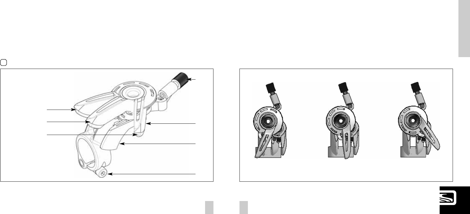
You will find the following positions on the remote
lever: [1]
Please note that you can only assemble the TRAC-
LOC remote lever in “left side upward position” on
the handlebar.
You have 3 positions of the TRAC-LOC remote lever.
- most forward position: LOCK OUT
- middle position: TRACTION MOEDE
- most backward position: ALL TRAVEL MODE
Change the modes by pushing the lever with your fingers
frontward and release them by tapping the release
button (one mode per push/release)
LOCK OUT MODE TRACTION MODE ALL TRAVEL MODE
FRANÇAIS DEUTSCH
07
ENGLISH
06
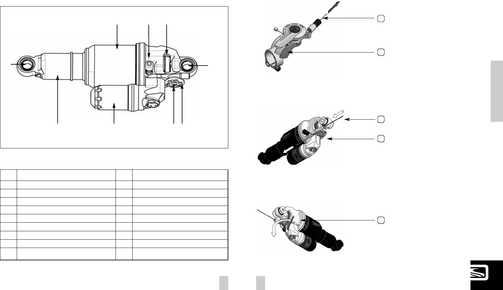
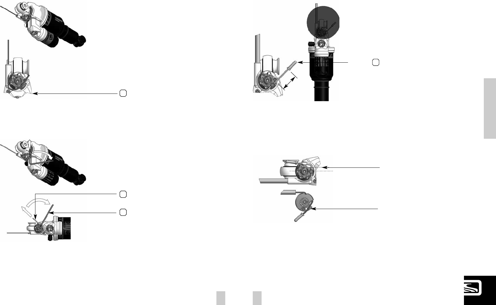
In the drawing of the shock and remote lever, shown
below, you will see the parts indicated with numbers
which will be used in the manual for the adjustment
and set-up.
NUDE TC SHOCK AND TRAC-LOC
REMOTE CONTROL LEVER
S1 Front eyelet/ Shock Bolt
S2 Rear eyelet/ Shock Bolt
S3 Piggy-Back
S4 Shock Housing
S5 Rebound-Screw
S6 Positive Chamber Valve
S7 Lock Out Barrel
S8 Cable fixing Screw
S9 Shock Piston
L1 Remote Lever
L2 Release Lever
L3 Tension Screw
L4 Allen Screw
S9 S3 S8 S7
S1
S5S6S4
S2
BASIC SET-UP OF THE
TRAC-LOC REMOTE CONTROL
OF NUDE TC SHOCK
To ensure perfect function of the Nude TC shock it is
very important to follow the steps shown below exactly
1thread in cable along the groove
and pull it tight gently
press the release lever twice whilst still pulling
the cable to set the lockout-lever into the
"open" position
2
...make it stepping out along the piggy back
4
Thread in the cable...
3
Unmount the M4 headless screw.
5
FRANÇAIS DEUTSCH
09
ENGLISH
08
BASIC SET-UP OF THE
TRAC-LOC REMOTE CONTROL
OF NUDE TC SHOCK
Create a loop and put it into the open groove on
the remote wheel..
6
Pull the cable tight...
7
...then tighten the headless 4mm-screw by using
a 2mm-Allen key (max 1.3Nm)
8
Put on the end cap and make sure to have at
least 17mm of free cable length.
9
17mm (min)
In Traction Mode about parallel to shock body
hang in cable
view from below
FRANÇAIS DEUTSCH
11
ENGLISH
10
The Set-Up of the Scott Nude TC Shock can be easy
done within a few minutes.
IImmppoorrttaanntt:: FFoorr aallll aaddjjuussttmmeennttss ooff tthhee
aaiirr sspprriinngg tthhee rreemmoottee lleevveerr hhaass ttoo bbee
iinn ppoossiittiioonn ““aallll ttrra
avveell””..
To adjust the air pressure of the positive chamber of
the Scott Nude TC Shock please refer to the following
instruction:
1. Remove the valve cap of the valve (S6) located on the
shock housing (S4).
2. Mount the shock pump with its adaptor on the valve
3. Pls take into account that it takes some air pressure
from inside the shock to drive the indicator on the pump.
Make sure to balance at least this air loss when you
make a check of the air pressure of the shock. Pls also
note that the indicators of shock pumps have a tolerance
of max. 10%
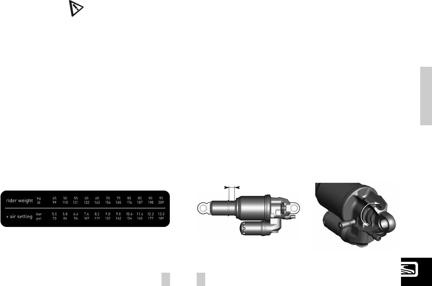
4. Pump the recommended pressure into the shock. On
the inner side of the left seatstays you will find a table
showing the recommended air pressure of the positive
chamber according to the rider’s weight.
5. When you reached the needed pressure remove the
pump and put the valve cap on the valve
SET-UP SPARK WITH
NUDE TC SHOCK
RECOMMENDED TOOLS
FOR THE SHOCK SET-UP
For the set-up of the shock we recommend to use a shock
pump with a scale up to 20 bars/300 psi with a special
air valve connector preventing from air getting away while
removing the pump from the shock valve, this will result
in an exact air pressure.
Please note that air will flow into the hose and indicator
when counterchecking the air pressure, so you have to
set up again the recommended pressure after this action.
The SAG should be 5mm on the shock piston.
To check the adjustment, please follow as shown below:
1. Sit on the bike, put your feet on the pedal
2. Put your feet back on the ground and stand over the
bike without bouncing the bike during this action
3. Check if the o-ring on the shock piston has a distance
of 5mm to the main dust wiper/seal between shock
housing and piston.
- if the distance between the o-ring and the main dust
wiper/seal is less than 5mm, the air pressure of the air
chamber is too high and should be carefully reduced by
using the bleed knob of the shock pump until the distance
is 5mm.
- if the distance between the main dust wiper/seal is
bigger than 5mm, the air pressure of the air chamber is
too low and should be increased by using the shock pump
until the distance is 5mm.
“Rebound” describes the speed the shock comes back
to its original length after absorbing an obstacle.
By using the red rebound screw (S6) you can adjust the
rebound step by step.
Please refer to the following instruction:
Ride your bike off a pavement (remain in the saddle)
and check how many times it bounces.
- if it bounces 1-2 times, the set up is good.
- If it bounces more than 3 times the rebound is
too fast. Turn the screw 1-2 “clicks” clockwise
- If it does not bounce the rebound is too slow.
Turn the screw 1-2 “clicks” counter clockwise.
SET-UP OF REBOUND
NUDE TC SHOCK
5mm
FRANÇAIS DEUTSCH
13
ENGLISH
12
Scott strongly recommends using only the originally
assembled Shock with the Spark bike, as we designed
both parts for a perfect matching combination.
For further set up instructions on those shocks please
follow the manuals of the shock producers attached to
the bike.
If you want to use a different rear shock model than the
one originally on the bike, please make sure that the
shock will not in any position hit the frame and cause
a damage to the frame.
Please follow the instruction below:
Please make sure that the rear shock or its accessory parts
do not touch the frame when mounting or suspending.
For doing so release the air/remove the coil, install
the shock and compress the shock completely.
IIff tthhee sshhoocckk ttoouucchheess tthhee ffrraammee wwhhiillee ddooiinngg ssoo,,
ddoo nnoott uussee tthhiiss sshhoocckk iinn oorrddeerr ttoo aavvooiidd dda
ammaaggee
ttoo ffrraammee,, sswwiinnggaarrmmoorr sshhoocckk..
SET-UP OF OTHER
SHOCK MODELS:
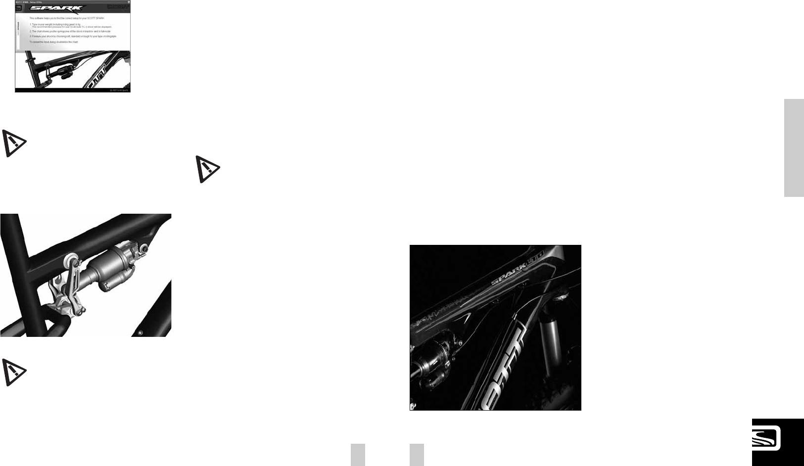
The direct and straight cable system on all our full
suspension models allows Smart Cable Routing which
is very resistant against water and dirt.
To change the cables simply unscrew and open the
cable brackets on the downtube.
SCOTT SEALED CABLE ROUTING:
The outer housing of the cables can also be fixed on
the bottle cage with cable fixers, the two brackets
below the cage are not needed anymore..
MECHANICS HINT
IImmppoorrttaanntt:: NNoottee tthhaatt yyoouu hhaavvee ttoo mmoouunntt tthhee
SSccootttt NNuuddee TTCC SShhoocckk aallwwaayyss aass sshhoowwnn uunnddeerr--
nneeaatthh..
MMoouunntti
inngg tthhee rreeaarr sshhoocckk iinn aa ddiiffffeerreenntt ppoossiittiioonn
ccaann ccaauussee sseevveerree ddaammaaggeess ttoo tthhee ffrraammee,, tthhee
lliinnkkaaggee lleevveerrss
aanndd tthhee rreeaarr sshhoocckk..
IImmppoorrttaanntt:: AAfftteerr aa ddiissmmaannttlleemmeenntt ooff tthhee rreeaarr
sshhoocckk,, bbootthh ffiixxiinngg bboollttss sshhoouulldd bbee ttiigghhtteenneedd
wwiitthh aa ttiigghhtteenniinngg ttoorrqquuee ooff 55NNmm//4444iinn--llbbss..
IIff tthhiiss iiss nnoott ddoonnee ccoorrrreeccttllyy tthhee rreeaarr sshhoocckk ccaann
bbee ddaammaaggeedd..
In case you want even more detailed figures of air
pressure or tuning hints, you can download a program
under www.scott-sports.com as a MS Excel file.
FRANÇAIS DEUTSCH
15
ENGLISH
14
IImmppoorrttaanntt:: ppllss nnoottee tthhaatt tthhee cchhaannggee ttoo aannootthheerr
ssaaddddllee oorr ppeeddaall mmooddeell mmiigghhtt iinnfflluueennccee aa lloott
tthhee lleennggtthh ooff tthhee sseeaatt ttuubbee!!
IImmppoorrttaanntt::
TThhee sseeaattppoosstt hhaass ttoo bbee iinnsseerrtteedd iinnttoo tthhee sseeaatt--
ttuubbee aatt aa mmiinniimmuumm ooff 1
10000mmmm..
NNeevveerr uussee aannootthheerr sseeaattppoosstt ddiiaammeetteerr tthhaann 3344..99mmmm oorr ttrryy
ttoo uussee aa sshhiimm//rreedduucceerr bbeettwweeeenn sseeaattppoosstt
aanndd ffrraammee..
IInn ccaassee yyoouurr bbiikkee iiss eeqquuiippppeedd wwiitthh aann iinntteeggrraatteedd sseeaattppoosstt
ppllss ffoollllooww tthhee iinnssttrruuccttiioonnss bbeel
looww ttoo ccuutt tthhee sseeaattttuubbeettoo
yyoouurr ppeerrssoonnaall lleennggtthh..
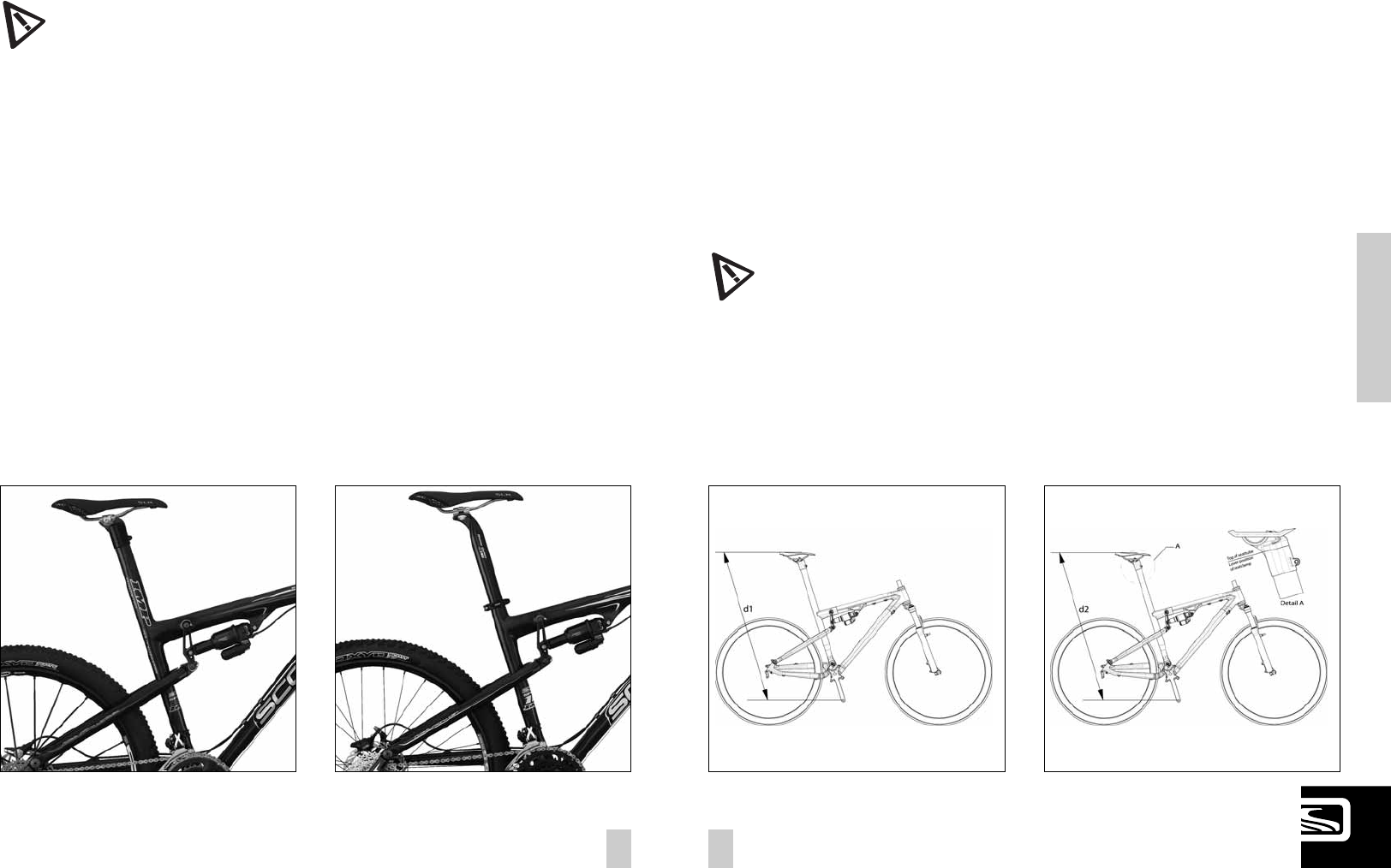
ADJUSTMENT
OF SEATPOST-HEIGHT
The seatpost of the Scott Spark needs to be cut and
adjusted to the personal seat height of the rider.
The tool to do so is added to your Spark and will help to
cut properly without any risk of damaging your seat tube.
To do so, pls follow the instructions given below:
1. Take the exact measure of the distance (d1) from the
mid of axle of your pedal to the upper side of the saddle
you use already on your “old” bike which is exactly
adjusted to your seat position.
standard seatpostintegrated seatpost
2. Mount your pedals and saddle on the Spark bike.
Fix the saddle with the M5 screws (4mm Allen key) by
using a tightening torque of 5Nm (44 in-lbs).
Your Spark seat clamp allows you to vary the seat
height for fine adjustment of +/- 10mm. For the cutting,
position your seat clamp as low as possible and measure
the distance (d2) from the mid of the pedal axle to the
upper side of the saddle.
Remove the seat clamp and measure the distance (l)
from the top of the seat tube: l = d2 – d1
FRANÇAIS DEUTSCH
17
ENGLISH
16
For the set up of the front fork please use the fork
specific manual attached to the bike.
We recommend using front forks with a travel of 100mm,
as this will not influence the geometry and alter hand-
ling of the bike.
FRONT FORK SET-UP /
CHANGE OF FRONT FORK
The pivot and bearings on SCOTT Spark are extremely
easy to maintain.
An external treatment with a grease spray after every
bike wash is all you have to do. We do not recommend
heavy grease sprays since these will leave a film on the
parts which is difficult to remove. We recommend the
same for the chain also.
If you have to change the bearings you can order them
included in a service kit at your local SCOTT dealer or
buy them with international parts number as shown
above in the specs list in a hardware store.
In case of a change of the bearings or of the rear swin-
garm you should contact your local SCOTT dealer as you
need special tools for disassembly and assembly
PIVOT MAINTENANCE:
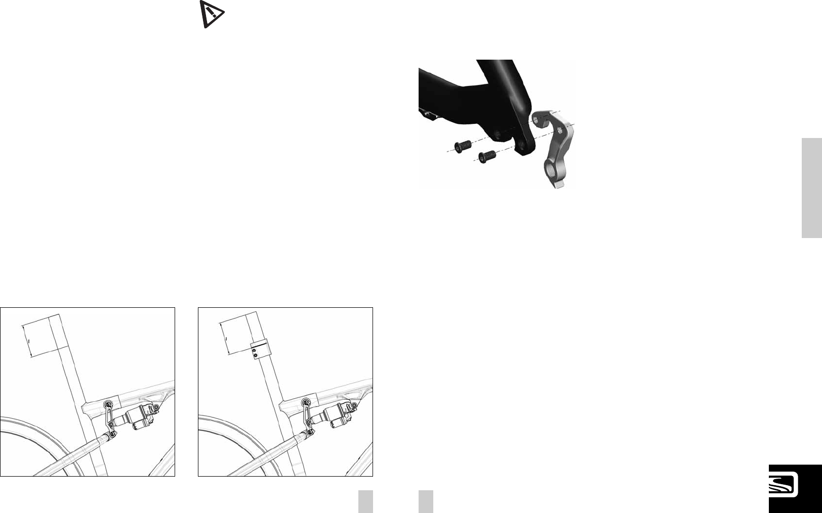
On Spark bikes of model year 07 you can replace the
rear derailleur hanger.
In case the replaceable hanger is damaged by a crash
or accident you can order at your local Scott dealer the
replacement part with Scott article number 206473
REPLACEABLE DROPOUT
6. Take a saw with a blade for cutting metal.
Plleeaassee oonnllyy uussee aa 1100DD//2244TT tteeeetthh bbllaaddee ttoo
mmaakkee ssuurree nnoott ttoo ddaammaaggee tthhee ccaarrbboonn ttuubbee
7. Cut the tube, remove the tool and take sandpaper
to smoothen the edges of the cutting area.
8. Remount the seat clamp in its middle adjustment
position (15mm over the top of the seat tube), fix the
2 M5 screws of the seat clamp (4mm Allen key) with
a tightening torque of 5Nm (44 in-lbs)
3. Indicate the length (l) you want to cut on the seat
tube with a marker pen.
4. Slide the Spark Cutting Tool on the seat tube of
Spark until the line of the marker is visible in the slot
on the tool that will guide your saw blade.
5. Fix the two 5mm bolts with a 4mm Allen key with a
tightening torque of 6 Nm (53 in-lbs).

FRANÇAIS DEUTSCH
19
ENGLISH
18
SCOTT bikes are made using the most innovative pro-
duction and quality methods. They are equipped with
best components of well known parts suppliers.
Doing so SCOTT warrants its frames and swingarms
for five years (subject to compliance with maintenance
ranges, see below) and SCOTT forks (provided it is
a fork of SCOTT) for two years for defects in material
and/or workmanship in case of purchase of completely
assembled bikes.
This warranty of 5 years for the frames shall only be
granted in case once a year a maintenance service has
been effected according to maintenance requirements
as set forth in this manual by an authorised SCOTT
dealer.
The authorised SCOTT dealer shall confirm the effected
annual maintenance service by stamp and signature.
In case such an annual maintenance service has not
been effected the warranty of 5 years for the frame
shall be reduced to 3 years.
Costs for maintenance and service have to be born
by the owner of the SCOTT bike.
On Gambler the warranty period is limited to 2 years.
The warranty period starts at the day of purchase.
This warranty is limited to the first buyer, what means
the first person who uses the bike and only with the
use it was made for. Furthermore, this warranty is limited
to purchases via authorized SCOTT-dealers to the
exclusion of purchases via internet auctions.
In case of a warranty claim the decision to repair or to
replace the defective part is up to SCOTT. Non defective
parts will only be replaced at the guarantee’s own
expense.
Fair wear and tear is not covered by the warranty.
A complete list of all parts of wear and tear can be
found in the next chapter of this manual.
In addition, you will find at the end of this manual a
protocol for the handing over of the bike which will
remain in copy at the SCOTT dealer after acceptance
and signature of the consumer.
It is obligatory to show this protocol of handing over
together with the defective part in case of a warranty
claim given that it provides evidence of purchase.
Otherwise no warranty is granted.
In principle, this warranty is granted worldwide.
Claims must be made through an authorized dealer,
for information regarding the nearest dealer, write or
call this company or the national SCOTT distributor.
Normal wear, accident, neglect, abuse, improper
assembly, improper maintenance by other than an
authorized dealer or use of parts or devices not consis-
tent with the use originally intended for the bicycle as
sold are not covered by this warranty.
Hereby SCOTT grants a voluntarily manufacturer’s war-
ranty. Additional entitlements according to national
warrant of merchantability are reserved.
For warranty info on the Nude TC shock please refer to
the attached manual of DT Swiss.
WARRANTY
Model __________________________
Year __________________________
Size __________________________
Frame # _________________________
Shock # _________________________
WARRANTY
