Bil Jax Satellite Tv System 36Xt Users Manual Operator’s
2015-02-02
: Bil-Jax Bil-Jax-Bil-Jax-Satellite-Tv-System-36Xt-Users-Manual-481372 bil-jax-bil-jax-satellite-tv-system-36xt-users-manual-481372 bil-jax pdf
Open the PDF directly: View PDF ![]() .
.
Page Count: 106 [warning: Documents this large are best viewed by clicking the View PDF Link!]
- PARTS AND SERVICE
- SELF-PROPELLED
- AERIAL WORK PLATFORM
- Drive Safety
- ALWAYS maintain an awareness of limited sight and blind spots when operating drive functions.
- ALWAYS limit travel speed according to surface conditions, slope, location of personnel and obstructions and any other factors which may result in collision.
- NEVER engage in stunt driving, horseplay or any other behavior considered unsafe according to employer, job site and/or government regulations.
- NEVER operate the internal combustion engine in an area that is not properly ventilated.
- General Maintenance
- DAMAGED EQUIPMENT POLICY
- There may be occasions when a Bil-Jax lift is involved in an accident resulting in damage to non-structural components. When such damage occurs and repairs are made by the owner or area distributor, please notify Bil-Jax of these non-maintenance repairs and request a repair form to be filled out and returned to Bil-Jax.
- 2 SPECIFICATIONS
- Direct any questions or concerns regarding equipment specifications to your regional Bil-Jax representative or to the Bil-Jax Service Department.
PARTS AND SERVICE
MANUAL
36XT
AERIAL WORK PLATFORMS
BOOM
TM

SELF-PROPELLED
AERIAL WORK PLATFORM
This equipment is designed and manufactured in
compliance with the duties, responsibilities and
standards set forth in the ANSI, CE, CSA and/or AS
standards in effect at the time of manufacture.
This equipment will meet or exceed applicable ANSI,
CE, CSA and/or AS codes and standards when operated
in accordance with manufacturer’s recommendations.
It is the responsibility of the user to follow all regional
codes and regulations that govern the safe operation of
this equipment.
Obtain, read and obey all safety precautions before
performing maintenance or repairs or attempting to
operate this equipment. This includes all manufacturer
recommendations as well as those directives set forth by
government and local authorities.
To ensure proper and safe use of this equipment, it is
strongly recommended that only trained and authorized
personnel attempt to operate and maintain the boom lift.
This manual shall be considered a permanent and
necessary component of the machine and shall be kept
with the boom lift at all times.
Owners and Lessors should complete a full inspection of
all components and perform a test of all functions,
including brake functions, before commissioning or
reselling the machine. Repair or replace all damaged or
malfunctioning components.
Bil-Jax, Inc. is dedicated to the continuous improvement
of this and all Bil-Jax products. Therefore, equipment
information is subject to change without notice. Direct
any questions or concerns regarding errors or
discrepancies in this manual to the Bil-Jax Service
Department.
Copyright © Bil-Jax, Inc. 2008. All Rights Reserved.
“Bil-Jax” is a registered trademark and “A Step Above”
and “X-Boom” are trademarks of Bil-Jax, Inc. Contact
Bil-Jax for replacement manuals.
125 Taylor Parkway
Archbold, Ohio 43502
Phone (800) 537-0540
(419) 445-8915
Fax (419) 445-0367
B33-01-0103 http://www.biljax.com

1
TABLE OF CONTENTS
Table of Contents 1
Illustrations 2
Tables 2
1 Safety 3
Legend: Safety Advisories 4
Before Operation 5
During Operation 5
Maintenance Safety 7
Damaged Equipment Policy 8
2 Specifications 9
Range of Motion 10
Specifications 11
Warranty 12
3 Equipment Maintenance 13
Daily Service Checks 14
Weekly Service Checks 16
Monthly Service Checks 17
Annual Service Checks 18
Structural Inspection 19
Additional Service Information 19
Troubleshooting 20
Error Code Definitions 21
4 Cylinder Replacement 25
Lift Cylinder Replacement 26
Outrigger Cylinder Replacement 27
5 Replacement Decals 29
6 Material Safety Data 35
Appendix: Replacement Parts 39
Ordering Replacement Parts 101

2
LIST OF ILLUSTRATIONS
Figure 2-1 Range of Motion 10
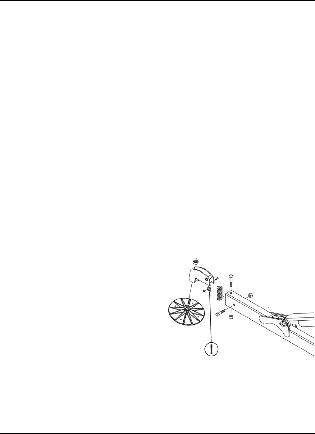
Figure 3-1 Outrigger Position Switch 14
Figure 3-2 Hydraulic Reservoir 15
Figure 3-3 Wheel Nut Tightening Sequence 17
Figure 3-4 Slew Ring Position Measurement 18
Figure 4-1 Lift Cylinder Replacement 26
Figure 4-2 Outrigger Cylinder Replacement 27
Figure 5-1 Decal Locations 31
Figure 5-2 Decal Locations – CE 33
LIST OF TABLES
Table 1-1 Minimum Safe Approach Distances 5
Table 3-2 Troubleshooting Steps 20
Table 3-3 Error Code Definitions 21
Table 5-1 Replacement Decal Descriptions 30
Table 5-2 Replacement Decal Descriptions – CE 32

3
1 SAFETY
Proper training is required for the safe operation of any mechanical device.
Failure to follow all instructions and safety precautions in this manual and
attached to the lift will result in death or personal injury.
Prior to Operation:
Read, understand and obey all instructions and safety precautions in this
manual and attached to the lift.
Read, understand and obey all applicable government regulations.
Become familiar with the proper use of all controls.
Inexperienced users should receive instruction before attempting to
operate or maintain the machine.
The use of intelligence and common sense is the best practice when
following any safety policy.
BIL-JAX 36XT
4
LEGEND: SAFETY ADVISORIES
The following safety advisories are used throughout
this manual to indicate specific hazards when
operating or maintaining the machine. Read,
understand and obey all safety advisories to prevent
improper service, damage to equipment, personal
injury or death.
DANGER
Warns of operation near electrical power
sources that could lead to personal injury or
death.
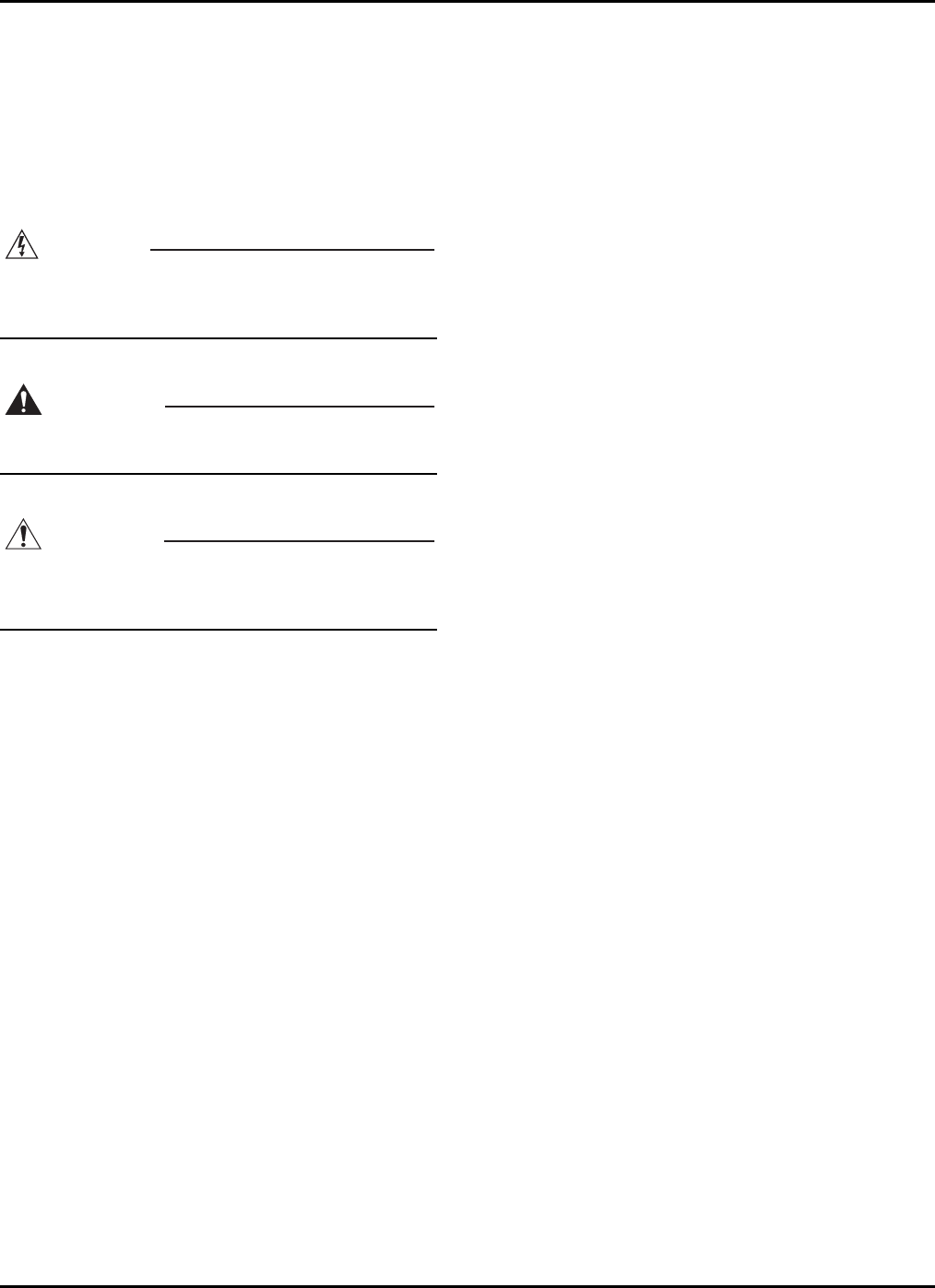
WARNING
Describes conditions or practices that could lead
to personal injury or death.
CAUTION
Contains information important in the prevention
of errors that could damage machine or
components.
NOTE: Contains additional information
important for performing a procedure.

1 — SAFETY
5
BEFORE OPERATION DURING OPERATION
Ensure the following general safety precautions are
followed before operating the articulating boom lift:
ALWAYS inspect the usage area for potential
hazards, such as unstable or unlevel surfaces,
overhead obstructions and electrically charged wires
or conductors. ALWAYS watch for moving vehicles
in the operating area.
ALWAYS conduct a thorough inspection of the
machine before operation. Check for damaged or
worn parts, hydraulic leaks, damaged wiring, loose
wiring conductors, damaged outriggers, low tire
pressure, uneven tire wear or tire damage. Check for
any improperly operating components. NEVER
operate equipment if any damage is observed or
suspected. Repair damaged or malfunctioning
equipment before operation.
ALWAYS wear proper clothing and footgear. Wear
protective equipment as required by government
regulations. Keep loose clothing, jewelry, gloves and
hair away from moving parts.
ALWAYS wear a safety harness and energy-
absorbing lanyard, such as a safety harness and
lanyard provided by Bil-Jax.
ALWAYS inspect platform floor and outrigger
footpads for mud, grease, debris or other foreign
material. ALWAYS remove any such material from
the equipment before operation.
ALWAYS tag any part of the equipment known or
suspected to be damaged or malfunctioning.
ALWAYS remove a malfunctioning, damaged or
defective machine from service. NEVER operate a
machine that has any known or suspected defect.
ALWAYS comply with the instructions found in
Safety and/or Service Bulletins distributed by the
manufacturer. Bulletins may contain critical
procedures that supersede the information
contained in manuals.
NEVER operate this equipment while under the
influence of drugs or alcohol, while taking
prescription medications that may leave the operator
drowsy or prone to dizziness, or while feeling ill.
NEVER modify the equipment in any way that would
affect its original design or operation.
NEVER deface, modify or obscure any decals or
markings on equipment.
NEVER operate the equipment in any way for which
it is not intended.
Ensure the following general safety precautions are
followed while operating the articulating boom lift:
ALWAYS position lift away from power lines to
ensure that no part of the lift can accidentally reach
into an unsafe area. This includes full extension of
the boom through 700º rotation.
DANGER
This machine is NOT insulated for use near
electrical power lines and DOES NOT provide
protection from contact with or close proximity
to any electrically charged conductor. Operator
must maintain safe clearances at all times (3.05
meters minimum) and must always allow for
platform movement due to gusty winds. Always
contact power company before working near
power lines. Assume every power line is live.
Power lines can be blown by the wind. Refer to
Table 1-1 for minimum safe approach distances
between the machine and electrical power lines.
Table 1-1. Minimum Safe Approach Distances
ALWAYS keep away from a machine that is
exposed to energized power lines. If the machine
contacts energized power lines, NEVER touch or
operate the machine until power lines are shut off.
ALWAYS operate only on a firm and level surface.
NEVER operate on surfaces that do not support the
equipment with its rated load capacity or on surfaces
that do not support force exerted by the outriggers
during boom operation. Operate only on surfaces
that can support a pressure of 1.8 kg/cm2 (25 psi) to
ensure safe operation.
ALWAYS keep personnel away from potential pinch
and shear points and from potential crush hazards
as indicated by decals attached to the machine.
ALWAYS keep the safety bar lowered unless
personnel are entering or exiting the work platform.
ALWAYS keep personnel and obstructions clear of
the machine when repositioning boom or basket.
Minimum Safe Approach Distance
Voltage Range
(Phase to Phase) (Feet) (Meters)
0 to 300V Avoid Contact
Over 300V to 50KV 10 3.05
Over 50KV to 200KV 15 4.60
Over 200KV to 350KV 20 6.10
Over 350KV to 500KV 25 7.62
Over 500KV to 750KV 35 10.67
Over 750KV to 1000KV 45 13.72

BIL-JAX 36XT
6
ALWAYS cordon the area surrounding the
outriggers to keep personnel, vehicles and moving
equipment away from the machine while in use.
ALWAYS stay clear of overhead obstructions,
including wires and cables.
ALWAYS engage boom travel latches before towing
trailer.
ALWAYS exercise caution when rotating the boom
from the ground control station. ALWAYS watch for
personnel inside the radius of the turntable and
boom arm when rotating the boom lift from the
ground or platform controls.
ALWAYS remove personnel from the boom lift
before attempting to free an elevated platform that
has become caught or snagged on an adjacent
structure or obstacle.
NEVER operate the machine on any surface other
than firm and level ground. NEVER operate the
machine from a position on truckbeds, trailers,
floating vessels or scaffolding without written
approval from the manufacturer.
NEVER operate lift functions on slopes exceeding
12.5º.
NEVER allow electrode contact with any part of the
machine while welding from the platform. NEVER
use the machine as a ground for welding.
NEVER operate without the outriggers fully
extended or when the machine is not level.
NEVER position an elevated platform against
another object to steady the platform
NEVER override or bypass the manufacturer’s
safety devices.
NEVER attach a safety harness to an adjacent
structure, pole, or to nearby equipment while
working from the boom platform.
NEVER raise the outriggers while boom is raised or
extended.
NEVER sit, stand or climb on cage bars. ALWAYS
keep both feet firmly on the work cage floor when
working from an elevated platform.
NEVER attempt to increase the working height with
boxes, ladders, stools or any other materials.
NEVER operate this equipment when exposed to
high winds, thunderstorms, ice or any weather
conditions that would compromise operator safety.
NEVER operate boom lift in conditions where wind
speeds exceed 12.5 m/sec (45 km/h or 28 mph).
High winds may affect stability and boom operation.
NEVER allow ropes, electric cords, hoses or other
equipment to become entangled in the machine
while raising or lowering platform.
NEVER exceed the load limits set by the
manufacturer. Use only the Material Lifting Hook,
supplied as an option and manufactured by Bil-Jax,
when lifting materials. Safely stow all tools and
equipment.
NEVER exceed load ratings by transferring loads to
the lift at elevated heights.
NEVER use the platform to lift a load that exceeds
the platform dimensions. NEVER lift a load in such a
way that the center of gravity is higher than the top
guardrail of the platform.
NEVER modify the platform or carry materials that
would increase the surface area of the platform.
Increasing the area exposed to the wind may
decrease machine stability. NEVER attach
overhanging loads when raising or lowering the
platform.
NEVER use the boom or platform to push or pull or
to lift any part of the machine.
NEVER use the boom or platform to place a load
against any structure, materials or equipment.
NEVER climb on the boom.
NEVER leave an elevated platform unattended.
NEVER leave the keys in the boom lift while
unattended or not in use.
Drive Safety
ALWAYS maintain an awareness of limited sight and
blind spots when operating drive functions.
ALWAYS limit travel speed according to surface
conditions, slope, location of personnel and
obstructions and any other factors which may result
in collision.
NEVER operate drive functions on slopes exceeding
20º.
NEVER engage in stunt driving, horseplay or any
other behavior considered unsafe according to
employer, job site and/or government regulations.
NEVER operate the internal combustion engine in
an area that is not properly ventilated.
NEVER fuel the internal combustion engine while
smoking, or while near spark or open flame.

1 — SAFETY
7
MAINTENANCE SAFETY
Ensure the following general safety precautions are
followed while performing maintenance on the
articulating boom lift:
General Maintenance
ALWAYS perform maintenance procedures
according to manufacturer’s guidelines. NEVER
disregard or bypass proper maintenance
procedures.
ALWAYS inspect hydraulic system to ensure that all
lines, connectors and fittings are properly fastened
and in good condition.
ALWAYS turn the key switch OFF and remove key
before performing maintenance.
ALWAYS perform maintenance with the boom and
platform in a fully lowered, stowed position, when
possible. ALWAYS secure the boom before
performing maintenance on hydraulic cylinders.
ALWAYS disconnect power to the hydraulic pump
drive motor before making electrical checks to the
hydraulic valves.
ALWAYS keep all mechanical parts properly
adjusted and lubricated according to maintenance
schedule and manufacturer’s specifications.
ALWAYS perform a function check of operating
controls before each use and after repairs have
been made.
ALWAYS locate and protect against possible pinch
points before performing any maintenance or
repairs.
ALWAYS use only manufacturer-approved parts to
repair or maintain equipment. If any portion of this
equipment is rebuilt or repaired, retesting is required
in accordance with factory instructions.
ALWAYS maintain a safe distance while testing the
hydraulic components. ALWAYS relieve hydraulic
pressure before loosening or removing hydraulic
components. NEVER test or operate the hydraulic
components while personnel are near the
equipment.
NEVER allow water or foreign particles into the DC
electric motor housing. Inclusion of water or foreign
particles may cause serious damage to the motor. If
the motor becomes wet, consult an authorized Bil-
Jax service technician for proper drying instructions.
NEVER add unauthorized fluids to the hydraulic
system or battery. NEVER mix hydraulic oils.
Consult manufacturer specifications. Refer to
Section 4 for hydraulic system maintenance
procedures.
NEVER exceed the manufacturer’s recommended
relief valve settings.
NEVER touch or allow metal tools to contact any
components that are sensitive to static discharge.
ALWAYS use static discharge prevention mats and
grounding devices when handling electronic
components.
NEVER adjust, repair, replace or bypass any
hydraulic or electrical control or safety device. These
include, but are not limited to, hydraulic load control
and flow control valves, solenoid valves and limit
switches. ALWAYS consult an authorized Bil-Jax
technician if repairs are necessary.
NEVER modify, alter or change the equipment
without first consulting an authorized Bil-Jax
technician, and NEVER in any way that would affect
its original design or operation.
Battery Maintenance
Ensure the following general safety precautions are
followed when performing battery maintenance on
the Aerial Work Platform.
ALWAYS wear safety glasses when working with or
near batteries.
ALWAYS check the battery fluid level daily.
ALWAYS avoid contact with battery acid. Battery
acid causes serious burns and should be kept away
from skin or eyes. If contact occurs, flush with water
and consult a physician immediately.
ALWAYS disconnect ground cable first when
removing battery.
ALWAYS connect ground cable last when installing
battery.
ALWAYS charge batteries in open, well-ventilated
areas.
ALWAYS replace batteries using only parts
recommended by manufacturer. ALWAYS use only
batteries with sealed caps over cells.
NEVER smoke while servicing batteries.
NEVER charge batteries near spark or open flame.
NEVER allow batteries to overcharge and boil.
NEVER short across battery posts to check for
current. NEVER break a live circuit at the battery.
NEVER disconnect battery from charger while
charger is connected to a live power source.
NEVER jumpstart other vehicles using the boom lift
batteries.

BIL-JAX 36XT
8
DAMAGED EQUIPMENT POLICY
Safety Statement
At Bil-Jax, we are dedicated to the safety of all users of our products. All Bil-Jax
lifts are designed, manufactured and tested to comply with current applicable
federal OSHA and ANSI codes and regulations.
Damage Policy
There may be occasions when a Bil-Jax lift is involved in an incident that results
in structural damage to the lift. Such damage can seriously compromise the
ability of the lift to perform in a safe manner. Therefore, whenever a Bil-Jax lift is
damaged structurally or when there is suspected internal damage to the
structure, Bil-Jax may require that the lift be returned to our facility for
reconditioning. For any questions concerning structural damage or the Damaged
Equipment Policy, please contact the Bil-Jax Service Department at 800-537-
0540.
Damage Repair Notice
There may be occasions when a Bil-Jax lift is involved in an accident resulting in
damage to non-structural components. When such damage occurs and repairs
are made by the owner or area distributor, please notify Bil-Jax of these non-
maintenance repairs and request a repair form to be filled out and returned to Bil-
Jax.

9
2 SPECIFICATIONS
Bil-Jax, Inc. is dedicated to the continuous improvement of this and all
Bil-Jax products. Therefore, equipment information is subject to change
without notice.
The following information is based on ideal working conditions. Machine
performance may vary based on work environment and on machine
options.
Direct any questions or concerns regarding equipment specifications to your
regional Bil-Jax representative or to the Bil-Jax Service Department.
BIL-JAX 36XT
10
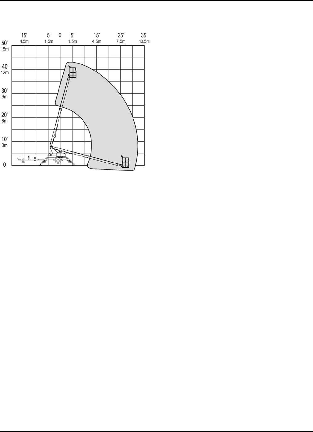
RANGE OF MOTION
Figure 2-1. Range of Motion

2 — SPECIFICATIONS
11
SPECIFICATIONS SERIAL NUMBER____________________________
Working Height
43 ft 6 in
13.4 m
Maximum Platform Height
37 ft 6 in
11.4 m
Maximum Horizontal Outreach
From Centerline
From Outrigger Footpad Edge
32 ft
9.8 m
27 ft
8.2 m
Rated Platform Capacity
Without Platform Rotation
With Platform Rotation
500 lbs
227 kg
440 lbs
200 kg
Maximum Occupants 2
Total Weight
4,680 lbs
2,123 kg
Turntable Rotation 700º Non-Continuous
Leveling Capability 12.5º
Gradeability 45%
Wheel Base
8 ft 8 in
2.7 m
Turning Radius
Inside
Outside
10 ft
3 m
18 ft
5.5 m
Platform Dimensions
Height
Length
Width – US/CE
3 ft 7 in
1.1 m
2 ft 6 in
0.8 m
5 ft/4 ft
1.5 m/1.2 m
Stowed Dimensions
Height
Length (Platform stowed)
Width
6 ft 6 in
2.0 m
20 ft 10 in
6.4 m
5 ft 5 in
1.7 m
Outrigger Footprint
Length
Width
Footpad Diameter
12 ft 2 in
3.7 m
11 ft 4 in
3.4 m
12.5 in
0.3 m
Brake Spring Applied
Speed
Gas Power
DC Power
1.5 mph
5.6 km/h
1.75 mph
2.8 km/h
Tire Size 26 x 12 bar lug tires
Tire Pressure
20 psi
140 kPa
Control System 24V DC
Battery 4 x 6V 245 amp-hr
Battery Charger 110/120 Volt
Gas Engine Kawasaki 21 HP
Hydraulic Pressure
3,000 PSI
20,684 kPa
Reservoir Capacity
4.8 Gallons
18.2 L
Hydraulic System Capacity
7 Gallons
26.5 L
Hydraulic Oil (Standard) Dexron III/Mercon ATF
Platform Rotation/Type (Optional) 90º/Manual
Maximum Decibel Level
DC Mode – Ground
DC Mode – Platform
Gas Mode – Ground
Gas Mode - Platform
60 dB
55 dB
70 dB
65 dB
Localized Pressure per Outrigger
25 PSI
1.8 kg/cm2
176.5 kPa
Operation Temperature Range
-20º to 110º Fahrenheit
-29º to 43º Celsius
Max. Pressure Per Tire – Floor
Loading
35 PSI
2.5 bar

BIL-JAX 36XT
12
WARRANTY
Bil-Jax, Inc. warrants this product for one year, beginning on the date of delivery,
to be free from defects of material and workmanship provided the unit is operated
and maintained in compliance with the guidelines established in the Operations
and Maintenance Manuals. Major structural components, including trailer tongue
and boom weldments, are warranted for five years against defects due to
material or workmanship. Bil-Jax will, at its option, repair or replace any unit or
component part that fails to function properly during normal use.
The warranty does not apply if the lift and/or its components have been altered,
changed, or repaired without the consent of Bil-Jax. Repairs, damage, or defects
resulting from the following are not covered under the terms of the warranty:
negligence, misuse, accidental damage, inadequate or improper maintenance,
acts of nature, damage caused by chemicals or abrasive materials, and normal
wear and tear, such as rust or corrosion. Components not covered under this
warranty include tires, filters, covers, and routine maintenance items.
Components not manufactured by Bil-Jax are covered be their respective
manufacturer’s warranties. A list of those components and their warranties is
available upon written request to Bil-Jax.
Bil-Jax shall not in any event be liable for the cost of any special, indirect, or
consequential damages to any person, product, or thing. Bil-Jax’s maximum
liability under this warranty is limited to the amount paid to Bil-Jax for the product.
This warranty is in lieu of all other warranties expressed or implied. Bil-Jax
neither assumes nor authorizes any or other entity to assume on its behalf any
other liability in connection with the sale, rental, or use of this product.
Warranty Claims Process
In order to qualify for warranty coverage, the following conditions must be met:
1) Return of completed “Warranty Registration” form to Bil-Jax within 15 days of
receipt of product;
2) Notification to Bil-Jax within 72 hours of any claimed defect, injury, or damage
resulting from the claimed the defect; and
3) Warranty is limited to parts that are determined to be defective. This does not
include parts worn out due to normal use.
Bil-Jax authorized dealers or distributors are responsible for filing claims under
warranty. Listed below is the warranty claims procedure.
1) Contact Bil-Jax Service Department at 800-537-0540 to report the claim and
verify warranty coverage. Machine serial number must be provided.
2) Identify the components to be claimed under warranty along with description of
failure. A Returned Merchandise Authorization (RMA) number will be issued by
Bil-Jax.
3) Replacement parts will then be sent by Bil-Jax to the dealer or distributor. All
parts are invoiced at dealer/distributor list price. Credits will be issued when
defective parts are returned to Bil-Jax and found to be defective under warranty.
4) After completing repairs, submit warranty claim form and defective parts to Bil-
Jax. Warranty claim form and parts must be received within 30 days of claim in
order to be eligible for credit. RMA number must be referenced on warranty claim
form. Returned parts are to be sent prepaid and will be credited when part is
received and verified. Warranty labor rate will be paid at current rate set by Bil-
Jax. The amount of labor hours reimbursed will be determined by Bil-Jax and will
be limited to 4 hours unless approved by Bil-Jax.
Failure to follow the warranty claims process may result in delay in processing
claim or denial of the claim. Bil-Jax reserves the right to limit or adjust warranty
claims with regard to parts, labor and travel time. Components purchased from
suppliers other than Bil-Jax are not covered under the terms of this warranty.

13
3 EQUIPMENT MAINTENANCE
Performing the appropriate maintenance procedures will extend the life
of the boom lift and will help ensure the safety of personnel operating the
equipment.
Repair, replacement or adjustment of any hydraulic or electrical control
device should be performed only by fully trained and authorized
personnel. These include, but are not limited to, hydraulic load valves,
hydraulic flow control valves, solenoid valves and limit switches. These
are safety related controls. Improper adjustment or tampering with these
devices may impair boom lift function and result in safety or damage
hazards.
Persons performing maintenance or repairs on the machine, including
weld repairs, should be trained in accordance with the manufacturer’s
recommendations. Contact your regional Bil-Jax representative if
additional information is needed.
Critical or suspect areas identified during any scheduled inspection of the
machine shall be examined by qualified personnel in accordance with
applicable government regulations.
Never operate the machine if a defect or malfunction is identified or
suspected. All defects and malfunctions must be repaired, and all
maintenance performed, before returning a machine to service.
This manual contains a list of recommended maintenance procedures to
be performed daily, weekly, monthly and annually.
When servicing the internal combustion engine installed on this
machine, always follow the guidelines specified by the engine
manufacturer.
It is the practice of Bil-Jax, Inc. to issue Service and/or Safety Bulletins,
which may include updates to the information contained in this manual.
In such instances, procedures contained in Bil-Jax Service Bulletins or
Safety Bulletins supersede the information contained in manuals.
Always follow maintenance schedule, regardless of use.
BIL-JAX 36XT
14
DAILY SERVICE CHECKS
The following maintenance procedures should be
performed daily or before each operation.
Verify that all decals are correctly applied and in
plain view.
Refer to Section 5 for decal locations.
Verify that all controls and indicators at ground
and platform control stations operate properly.
Lower outriggers to level the boom lift.
Raise and extend all booms.
Press emergency STOP button.
Verify that booms remain elevated and do not drift.
Pull out STOP button and lower the booms.
If either control station is unresponsive, refer to Table
3-1 for troubleshooting procedures.
If display panel displays an error code, refer to Table
3-2 for error code definitions.
Verify correct tire inflation.
Inflate tires to 20 psi (140 kPa).
Inspect tires for damage or loose or missing lug
nuts.
Repair or replace as necessary.*
Inspect structural components and platform for
obvious damage or debris.
Repair or replace as necessary.
Inspect machine for missing, loose or damaged
fasteners, including pins and bolts.
Check engine oil level.
Add oil as needed.
Manufacturer recommends engine oil type 5W-30.
Check engine fuel level.
Add fuel as needed.
Verify that boom down limit switches operate
correctly.
Down limit switches are actuated when the boom is in
a fully lowered, stowed position. Limit switches must
be operational to raise or lower outriggers.
If outrigger controls are unresponsive when boom is
fully lowered and stowed, inspect down limit switches
for loose mounting or visible damage.
Repair or replace as needed.
Verify that outrigger safety interlocks operate
correctly.
Begin with the outriggers fully extended and the boom
lift level. Raise one outrigger until the footpad is not in
contact with the ground.
Verify that boom functions are unresponsive when
one outrigger is raised.
Repeat this procedure for each outrigger.
Raise all outriggers until the footpads are not in
contact with the ground. Verify that all outrigger status
LEDs on the ground control panel are unlit.
Lower one outrigger until the footpad makes contact
with the ground and the outrigger begins lifting the
trailer.
If the LED is lit before the footpad makes contact with
the ground or if the LED remains unlit after the weight
is transferred to the outrigger, the position switch or
wiring is faulty.
Repeat this procedure for each outrigger.
Repair or replace as needed. Refer to Figure 2-1.
Figure 3-1. Outrigger Position Switches
*Repair and replacement of machine components should
be performed only by trained and certified personnel in
accordance with government regulations and
manufacturer recommendations.
3 — EQUIPMENT MAINTENANCE
15
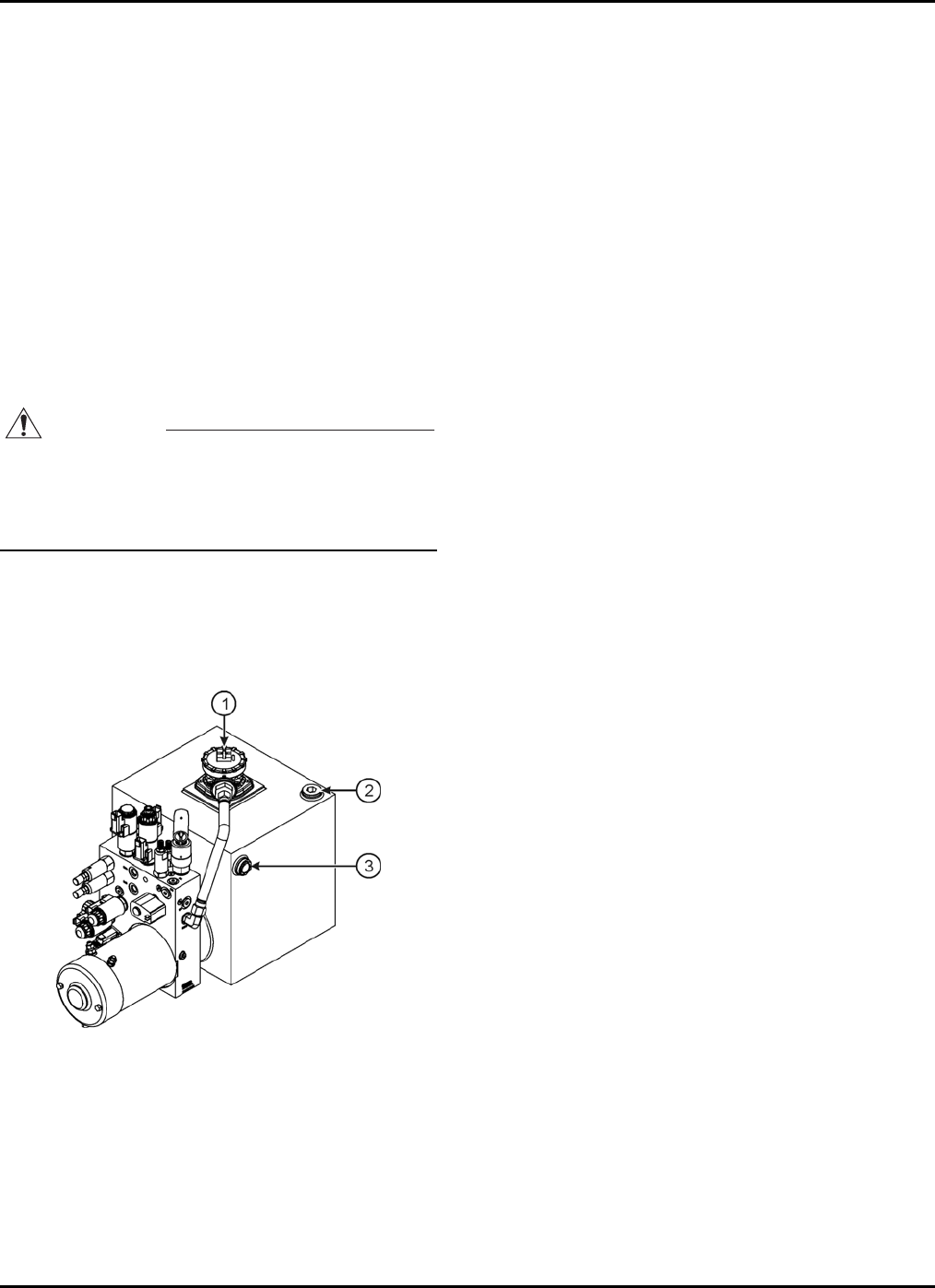
Inspect hydraulic system and fluid levels.
Check all hydraulic hoses and fittings for leaks and
damage. Tighten or replace as necessary to prevent
hydraulic oil or pressure loss.
The hydraulic oil level should be checked with the
booms down, all outriggers raised and the trailer
wheels on a level surface.
Hydraulic oil level should be visible in, but not above,
the sight gauge.
If the hydraulic oil level is not visible to at least half
way up the sight gauge (Figure 3-2), add clean
hydraulic fluid as necessary while all booms and
outriggers are fully retracted and stowed. Pour slowly
to avoid creating air pockets in the reservoir. Do not
fill above sight gauge. Overfilling the hydraulic
reservoir may cause damage to hydraulic lines and
may result in equipment malfunction.
CAUTION
Do not mix hydraulic oils. Do not add any fluid to
the hydraulic system that is not expressly
recommended by the manufacturer. Adding
unauthorized fluids to the hydraulic system may
cause damage to equipment
The hydraulic reservoir is originally filled with Dexron
III/Mercon ATF with a viscosity rating of 175.
Manufacturer recommends a higher viscosity
hydraulic oil when operating equipment routinely in
extreme climates.
1. Filter Element
2. Fill Port
3. Sight Gauge
Figure 3-2. Hydraulic Reservoir

BIL-JAX 36XT
16
WEEKLY SERVICE CHECKS
Perform the following service checks at least once
each week in addition to all recommended Daily
Service Checks:
Check Battery electrolyte level.
If electrolyte level is low, add enough water to bring
the electrolyte level to the top of the plates.
If batteries are fully charged, raise electrolyte level to
full mark in each cell.
Inspect all electrical wiring.
Check for cuts, loose terminals, broken wires, chaffing
and corrosion.
Repair all damage, remove corrosion and seal
exposed connections.
Inspect boom lift for missing, loose or damaged
hardware.
Repair or replace as necessary.
Inspect all hydraulic system components
including pump and motor and cylinders for
damage, leaks, loss of pressure or speed, and
unusual noise or vibration.
Repair or replace as necessary.

3 — EQUIPMENT MAINTENANCE
17
MONTHLY SERVICE CHECKS
Perform the following service checks at least once
each month:
Clean all battery terminals.
Check battery for loose connections or damaged
wires.
Verify proper operation of manual lowering
valves and hand pump
Refer to Section 3 for manual boom operating
procedures.
Lubricate all compartment hinges and latches,
slew ring and mating gear.
Use NLGI Grade 2 multi-purpose grease.
Check wheel nut torque.
Refer to Figure 4-3 for correct wheel nut tightening
sequence.
Evenly tighten wheel nuts to 34 N*m in the tightening
sequence shown.
Repeat sequence, tightening wheel nuts to 81 N*m
and to 136 N*m.
NOTE: Follow this procedure each time the
wheel is removed and reinstalled.
4
5
1
2
3
Figure 3-3. Wheel Nut Tightening Sequence
BIL-JAX 36XT
18
ANNUAL SERVICE CHECKS
Perform the following service checks at least once
each year:
Replace Hydraulic Oil and Oil Filter.
Drain hydraulic reservoir, clean and replace oil.
Wipe away dirt and excess oil from around filter using
cleaning cloths and alcohol solvent.
Loosen and remove filter. Use absorbent cloths to
keep excess oil from leaking onto the machine.
Discard used filter.
Wipe away dirt and excess oil from around filter
housing.
Install new filter. Do not over-tighten.
With the fill port cap on but not tightened, completely
raise and lower all booms to bleed trapped air from
the lift cylinders. Repeat as necessary.
Replace yearly, or whenever filter or oil contamination
has a noticeable effect on boom functions.
Inspect pivot pins and cylinders, including rod
ends, for wear or damage. Replace as necessary.
Visually inspect welds and structural
components for wear, damage and corrosion.
Follow all manufacturer’s recommendations when
making repairs to critical components.
Personnel making repairs to welds should be certified
in accordance with applicable government
regulations.
Inspect outriggers for wear or damage. Repair or
replace as necessary.
Verify that Level Sensor is operating correctly.
Fully deploy outriggers until all Outrigger LEDs and
AUTO LEVEL LED are lit, and buzzer sounds.
Verify that machine is level, and that level sensor is
giving an accurate reading.
Repair or replace as necessary.
Inspect and adjust axles and brakes.
Load test boom lift operations with 500 lb (187
kg) load.
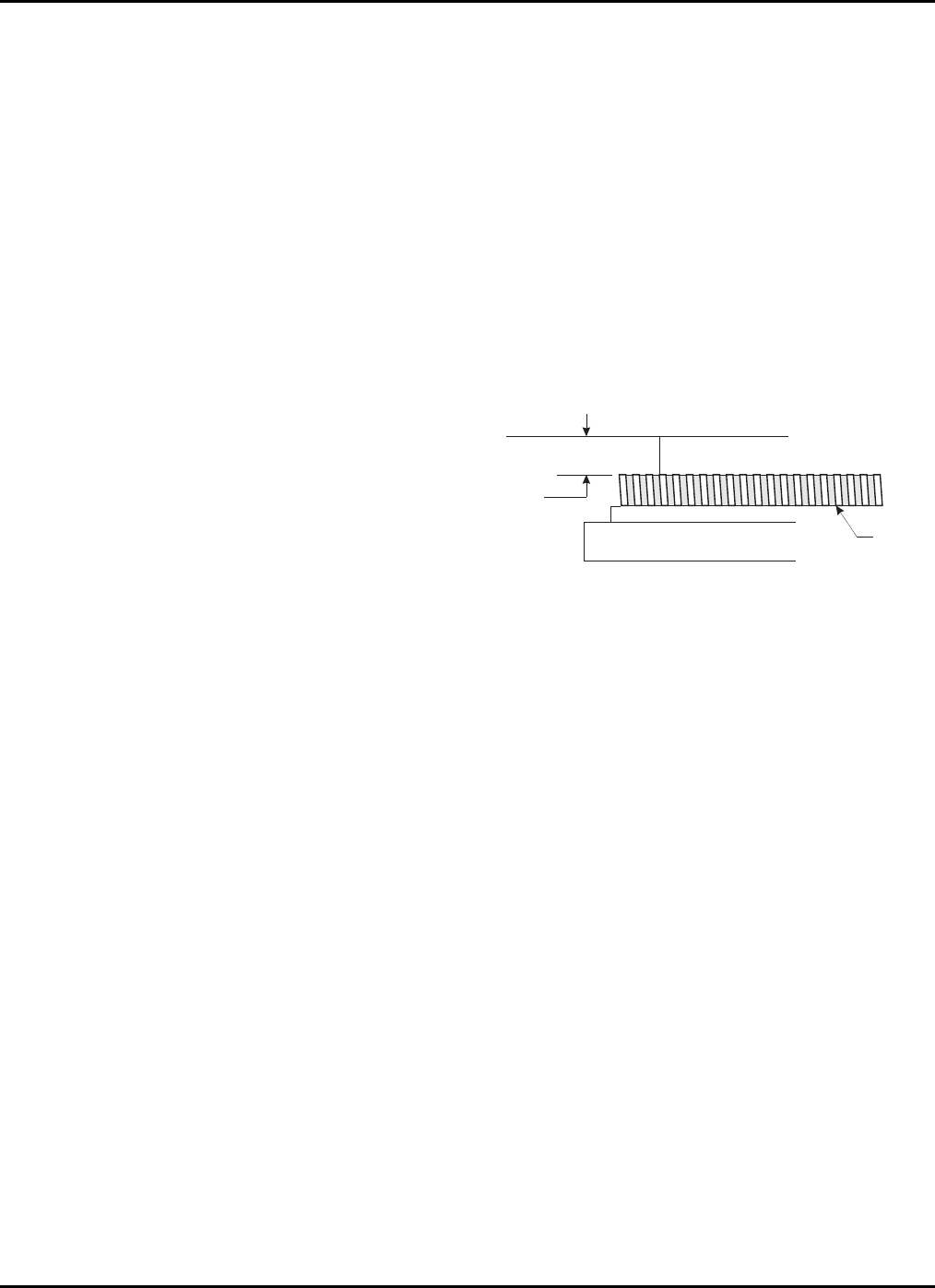
Check slew bearing for wear or damage.
Check bolts for wear or damage.
With the boom lift fully retracted, measure the
distance between the slew ring gear and the
horizontal plate above. Use a 2-inch (50 mm) caliper
or bore micrometer. Record the measurement (Figure
3-4).
Place a 175 lb (65 kg) load on the boom lift platform.
Measure the distance between the slew ring and the
horizontal plate above. Record the measurement.
If the difference in measurements is greater than .25
in (6.35 mm) the slew ring bearing should be
replaced. Contact manufacturer for replacement
instructions and assistance.
MEASURE
HERE
SLEW RING
Figure 3-4. Slew Ring Position Measurement

3 — EQUIPMENT MAINTENANCE
19
STRUCTURAL INSPECTION ADDITIONAL SERVICE INFORMATION
A comprehensive structural inspection of the unit
shall be performed under any of the following
conditions.
Ten years from the date of manufacture and every
five years thereafter.
After any actual, suspected or potential damage is
sustained that could affect the structural integrity or
stability of the aerial platform.
After a change in ownership. Owners should provide
a complete service history when reselling the unit.
The structural inspection shall include the following
considerations.
The service history of the unit, including hours of
service, work performed and environmental
conditions.
The inspection and maintenance record of the unit.
The effectiveness of all controls and components.
A visual inspection of the unit for wear or damage.
Manufacturer recommendations.
A visual weld inspection, to be performed by qualified
personnel in accordance with applicable government
regulations.
Seals on hydraulic cylinders should be replaced every five
years or as indicated by machine performance.
All service checks should be performed on a machine that
has been stored without use for a period exceeding thirty
days.
Check for air in the hydraulic system if the machine has
been stored without use for a period exceeding thirty days,
or if the machine was stored without use during a
seasonal climate change. Air trapped in the hydraulic
system will affect machine performance. Follow
procedures for bleeding air from the hydraulic system,
found in Section 4.
Owners and lessors should complete a full inspection of all
components and perform a test of all functions, including
brake functions, before commissioning or reselling
machine. Always repair or replace all damaged or
malfunctioning components before commissioning or
reselling machine.
When a change in ownership occurs, it is the responsibility
of the seller to provide the new owner with all manuals for
the machine. It is the responsibility of the buyer to notify
the manufacturer of the unit model and serial number and
the name and address of the new owner within 60 days.
Use the Service Checklists found at the back of the
Operator’s Manual to record all Service Checks as well as
any maintenance, repairs or alterations performed on the
machine.
Records of frequent safety checks need not be made.
However, where a safety hazard is found, it shall be
reported in writing to the owner of the machine, and a
record of any corrective action shall be maintained for five
years or as required b y the authority having jurisdiction.
Testing Machine Stability
The Summit Series aerial work platform has been tested
for stability using a load equal to 150% of the rated
capacity of the machine and placed at the center of the
platform with the boom fully extended. Stability tests
should be conducted only by trained personnel and only
when the machine is properly anchored to safeguard
against tipping.

BIL-JAX 36XT
20
TROUBLESHOOTING
Refer to Table 3-2 for basic troubleshooting operations. Additional information
can be found in the Bil-Jax Model 45XA Operator’s Manual. Contact the Bil-Jax
Service Department with any questions or before attempting any advanced
troubleshooting operations.
Table 3-1. Troubleshooting Steps
PROBLEM CAUSE SOLUTION
No lights on panel when
key switch is turned to the
on position.
a. Emergency STOP engaged.
b. Battery charge is low.
c. Battery ground or in-series cable is loose.
d. Battery main disconnect unplugged.
a. Disengage Emergency STOP buttons.
b. Recharge as needed.
c. Inspect and repair battery connections.
d. Plug in main disconnect.
Hydraulic function does not
work and display window
shows an error message
a. Fault detected by safety interlock
microprocessor.
b. Boom Lift electric or electronic failure
a. Refer to Table 4-2 for error code
definition and correction.
b. Refer to Table 4-2 for error code
definition and correction.
Outrigger indicator LED
lights do not function. a. Key switch turned to the OFF or platform
controls position.
b. Emergency STOP engaged.
c. Outriggers not deployed.
a. Turn key switch to ground controls
position.
b. Disengage emergency STOP buttons.
c. Deploy all outriggers.
One or more boom controls
do not function
OR
One or more boom controls
function improperly
OR
One or more boom controls
function intermittently.
a. Key switch is turned to the OFF or
incorrect control position.
b. Battery charge is low.
c. Emergency
STOP engaged.
d. Battery ground or in-series cable loose.
e. All outriggers not properly deployed.
f. Hydraulic pump inoperative.
g. Loose wiring connector.
h. Valve solenoid not operating properly.
i. Fault detected by system interlock.
j. Broken or loose wire.
a. Turn key switch to ground or platform
controls position.
b. Recharge battery.
c. Disengage Emergency STOP buttons.
d. Inspect and repair battery connections.
e. Deploy all outriggers and level boom lift.
f. Inspect pump; replace or repair as
needed.
g. Check wiring terminals in control box
and at valve manifold; replace or repair
as needed.
h. Clean valve solenoid and recheck
function(s); replace or repair as needed.
i. Check display for system status. Refer
to Table 4-2 for error code definitions
and correction.
j. Inspect wiring in control box and at
valve manifold and valve coil; repair or
replace as needed.

3 — EQUIPMENT MAINTENANCE
21
ERROR CODE DEFINITIONS
The DISPLAY PANEL located on the ground control panel indicates the present
operating status of the boom lift. If an error condition is detected by the control
processor during start-up or operation, the appropriate error code will be
displayed on this panel.
Refer to Table 3-2 for a comprehensive list of Error Code Definitions and
solutions.
Table 3-2. Error Code Definitions
ERROR MESSAGE DEFINITION OF ERROR COMMENTS
001 MACHINE IS IN DOWN ONLY
MODE Machine was either never leveled, outriggers not
lowered, or machine went out of level with use. Retract boom to travel position
and extend outriggers using AUTO
LEVEL button.
002 LOSS OF PLATFORM
COMMUNICATION Ground control lost communication with platform
control. Check for unplugged or damaged
platform control cable.
005 PLATFORM CONTROL HAS
STUCK KEY Platform control detected a stuck or pressed key
on power up. Turn key switch off and on again
without pressing any buttons.
008 GROUND CONTROL HAS
STUCK KEY Ground control detected a stuck or pressed key
on power up. Turn key switch off and on again
without pressing any buttons.
009 BOOM UP WITHOUT
OUTRIGGERS ON GROUND Ground control detected the boom is up and all
outriggers are not on the ground Retract boom to travel position
and extend outriggers using AUTO
LEVEL button.
010 LEVEL SENSOR HAS
ERRATIC OUTPUT The ground control detected an erratic output
from the level sensor. Retract and extend outriggers
using AUTO LEVEL button.
015 MACHINE IS NOT LEVEL Machine has gone out of level with use. Retract and extend outriggers
using AUTO LEVEL.
016 LIFT BOOM A boom rotate, extend, or retract function
requested with boom down. Raise boom from travel position.
017 STOW BOOM An outrigger function requested with boom up. Retract and lower boom to travel
position.
021 OPEN CIRCUIT PRIMARY UP A load of less than 70mA detected in primary up
circuit on power-up. Check for faulty boom up
solenoid coil and wiring.
022 SHORTED CIRCUIT
PRIMARY UP Excessive load detected in primary up circuit on
power-up. Check for faulty boom up
solenoid coil and wiring.
023 OPEN CIRCUIT PRIMARY
DOWN A load of less than 70mA was detected when
primary down circuit was energized Check for faulty boom down
solenoid coil and wiring.
024 SHORTED CIRCUIT
PRIMARY DOWN Excessive load detected when primary down
circuit was energized. Check for faulty boom down
solenoid coil and wiring.
025 OPEN CIRCUIT SECONDARY
UP A load of less than 70mA detected in secondary
up circuit on power-up. Check for faulty boom up
solenoid coil and wiring.
026 SHORTED CIRCUIT
SECONDARY UP Excessive load detected in secondary up circuit
on power-up. Check for faulty boom up
solenoid coil and wiring.
027 OPEN CIRCUIT SECONDARY
DOWN A load of less than 70mA detected when
secondary down circuit was energized Check for faulty boom down
solenoid coil and wiring.
028 SHORTED CIRCUIT
SECONDARY DOWN Excessive load detected when secondary down
circuit was energized. Check for faulty boom down
solenoid coil and wiring.
029 OPEN CIRCUIT JIB UP A load of less than 70mA detected in jib up circuit
on power-up. Check for faulty jib up solenoid
coil and wiring.
030 SHORTED CIRCUIT JIB UP Excessive load detected in jib up circuit on
power-up. Check for faulty jib up solenoid
coil and wiring.

BIL-JAX 36XT
22
ERROR MESSAGE DEFINITION OF ERROR COMMENTS
031 OPEN CIRCUIT JIB DOWN A load of less than 70mA detected when jib down
circuit was energized Check for faulty jib down solenoid
coil and wiring.
032 SHORTED CIRCUIT JIB
DOWN Excessive load detected when jib down circuit
was energized. Check for faulty jib down solenoid
coil and wiring.
033 OPEN CIRCUIT EXTEND A load of less than 70mA detected in extend
circuit on power-up. Check for faulty boom extend
solenoid coil/wiring.
034 SHORTED CIRCUIT EXTEND Excessive load detected in extend circuit on
power-up. Check for faulty boom extend
solenoid coil/wiring.
035 OPEN CIRCUIT RETRACT A load of less than 70mA detected in retract
circuit on power-up. Check for faulty boom retract
solenoid coil/wiring.
036 SHORTED CIRCUIT
RETRACT Excessive load detected in retract circuit on
power-up. Check for faulty boom retract
solenoid coil/wiring.
037 OPEN CIRCUIT PLATFORM
LEVEL UP A load of less than 70mA detected in platform
level up circuit on power-up. Check for faulty level up solenoid
coil/wiring.
038 SHORTED CIRCUIT
PLATFORM LEVEL UP Excessive load detected in platform level up
circuit on power-up. Check for faulty level up solenoid
coil/wiring.
039 OPEN CIRCUIT PLATFORM
LEVEL DOWN A load of less than 70mA detected in platform
level down circuit on power-up. Check for faulty level down
solenoid coil/wiring.
040 SHORTED CIRCUIT
PLATFORM LEVEL DOWN Excessive load detected in platform level down
circuit on power-up. Check for faulty level down
solenoid coil/wiring.
041 OPEN CIRCUIT PLATFORM
CW A load of less than 70mA detected in platform
CW circuit on power-up. Check for faulty boom rotate
solenoid coil/wiring.
042 SHORTED CIRCUIT
PLATFORM CW Excessive load detected in platform CW circuit
on power-up. Check for faulty boom rotate
solenoid coil/wiring.
043 OPEN CIRCUIT PLATFORM
CCW A load of less than 70mA detected in platform
CCW circuit on power-up. Check for faulty boom rotate
solenoid coil/wiring.
044 SHORTED CIRCUIT
PLATFORM CCW Excessive load detected in platform CCW circuit
on power-up. Check for faulty boom rotate
solenoid coil/wiring.
045 OPEN CIRCUIT TURNTABLE
CW A load of less than 70mA detected in rotate CW
circuit on power-up. Check for faulty rotate CW
solenoid coil/wiring.
046 SHORTED CIRCUIT
TURNTABLE CW Excessive load detected in rotate CW circuit on
power-up. Check for faulty rotate CW
solenoid coil/wiring.
047 OPEN CIRCUIT TURNTABLE
CCW A load of less than 70mA detected in rotate CCW
circuit on power-up. Check for faulty rotate CCW
solenoid coil/wiring.
048 SHORTED CIRCUIT
TURNTABLE CCW Excessive load detected in rotate CCW circuit on
power-up. Check for faulty rotate CCW
solenoid coil/wiring.
049 OPEN CIRCUIT OUTRIGGER
RETRACT A load of less than 70mA detected in outrigger
retract circuit on power-up. Check for faulty outrigger retract
solenoid coil/wiring.
050 SHORTED CIRCUIT
OUTRIGGER RETRACT Excessive load was detected when Outrigger
Retract circuit was energized. Check for faulty outrigger retract
solenoid coil/wiring.
051 OPEN CIRCUIT OUTRIGGER
EXTEND A load of less than 70mA detected in outrigger
retract circuit on power-up. Check for faulty outrigger extend
solenoid coil/wiring.
052 SHORTED CIRCUIT
OUTRIGGER EXTEND Excessive load was detected in outrigger extend
circuit on power-up. Check for faulty outrigger extend
solenoid coil/wiring.
053 OPEN CIRCUIT
LF OUTRIGGER A load of less than 70mA detected in left front
outrigger circuit on power-up. Check for faulty solenoid
coil/wiring at outrigger.
054 SHORTED CIRCUIT
LF OUTRIGGER Excessive load was detected in left front
outrigger circuit on power-up. Check for faulty solenoid
coil/wiring at outrigger.
055 OPEN CIRCUIT
RF OUTRIGGER A load of less than 70mA detected in right front
outrigger circuit on power-up. Check for faulty solenoid
coil/wiring at outrigger.

3 — EQUIPMENT MAINTENANCE
23
ERROR MESSAGE DEFINITION OF ERROR COMMENTS
056 SHORTED CIRCUIT
RF OUTRIGGER Excessive load detected in right front outrigger
circuit on power-up. Check for faulty solenoid
coil/wiring at outrigger.
057 OPEN CIRCUIT
LR OUTRIGGER A load of less than 70mA detected in left rear
outrigger circuit on power-up. Check for faulty solenoid
coil/wiring at outrigger.
058 SHORTED CIRCUIT
LR OUTRIGGER Excessive load detected in left rear outrigger
circuit on power-up. Check for faulty solenoid
coil/wiring at outrigger.
059 OPEN CIRCUIT
RR OUTRIGGER A load of less than 70mA detected in right rear
outrigger circuit on power-up. Check for faulty solenoid
coil/wiring at outrigger.
060 SHORTED CIRCUIT
RR OUTRIGGER Excessive load detected in right rear outrigger
circuit on power-up. Check for faulty solenoid
coil/wiring at outrigger.
069 OPEN CIRCUIT
PROPORTIONAL A load of less than 70mA detected in proportional
valve circuit on power-up. Check for faulty solenoid
coil/wiring at proportional valve.
070 SHORTED CIRCUIT
PROPORTIONAL Excessive load detected in proportional valve
circuit on power-up. Check for faulty solenoid
coil/wiring at proportional valve.

BIL-JAX 36XT
24

25
4 CYLINDER REPLACEMENT
If repair or replacement of a boom lift or outrigger hydraulic cylinder or its
component parts becomes necessary, observe the following procedures in
accordance with the safety precautions established in Section 1 of this manual.
Removing the hydraulic cylinder from the boom lift may require the use of
specialized tools and lifting equipment. NEVER attempt to operate overhead
hoists or cranes or related equipment without proper training, authorization and
supervision. Perform all maintenance procedures only in an area that is well-lit
and well-ventilated. Bil-Jax, Inc. is not responsible for personal injury or property
damage resulting from the improper use of equipment or failure to follow all
procedures and related safety precautions.
Direct all questions regarding cylinder removal and replacement to your regional
Bil-Jax representative or to the Bil-Jax Service Department at 800-537-0540.
BIL-JAX 36XT
26
LIFT CYLINDER REPLACEMENT
Use the following procedure to remove and replace
faulty or damaged hydraulic cylinders on the boom
lift:
WARNING
Repair and removal of the hydraulic cylinders
requires the use of lifting straps and an
overhead crane or lifting gear to support the
boom lift and hydraulic cylinders. Personnel
should be thoroughly trained in the operation of
these devices before attempting installation or
removal. Hydraulic cylinders are heavy and may
have hydraulic oil on their surface. Failure to use
proper equipment or to securely support boom
and boom cylinders can result in damage to lift
components, serious injury or death.
Lower the boom until it is resting in a stowed position.
When removing the slave cylinder, extend the
articulating boom section until all pivot pins are
exposed (approximately two feet).
Press and hold the emergency lowering valve on the
back of the jib boom section to relieve all hydraulic
pressure to the cylinder. Repeat this process for the
upper and lower boom sections. Refer to the 4527A
Operator’s Manual for emergency lowering valve
locations and operating procedures.
Turn key switch to the OFF position and remove the
key.
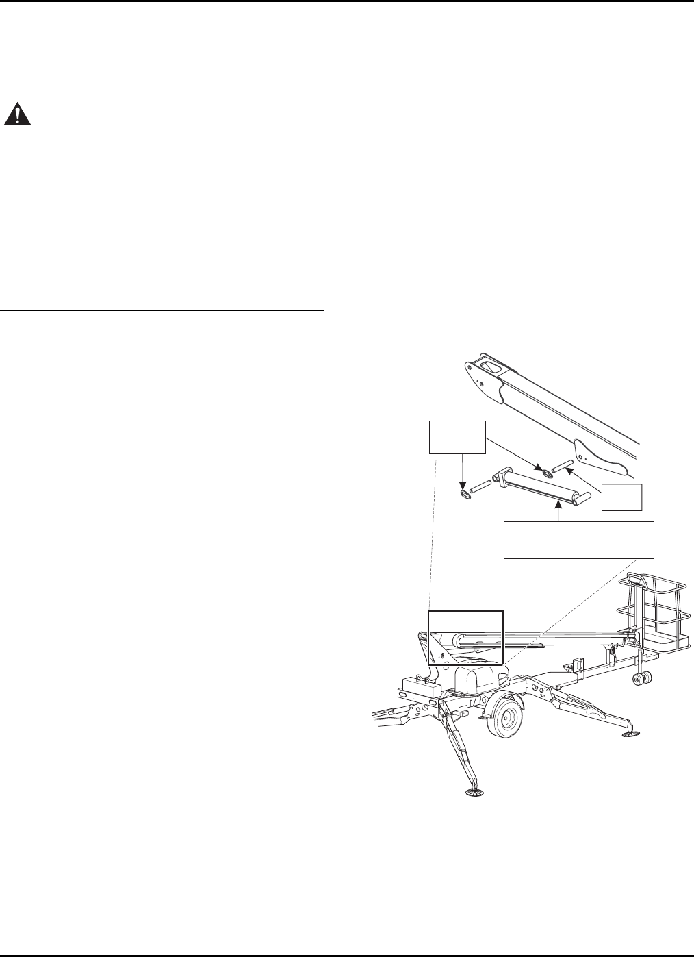
Locate the piston rod end of the cylinder to be
removed (Figure 4-1). Unbolt and remove the retainer
plate from each side of the pivot pin.
Verify that the cylinder is supported by lifting straps
and an overhead hoist.
Remove the pivot pin using a hammer and a brass or
hardwood drift.
Use an overhead crane or lifting gear to raise the
boom section. Adequate clearance is necessary to
reach the cylinder valve block and hydraulic hose
ports.
Unplug the appropriate emergency lowering valve
solenoid.
Tag and number all hydraulic hoses that attach to the
cylinder valve block. Use a marker to label the valve
block ports with the appropriate hose numbers.
Place absorbent cloths below the cylinder ports and
detach hydraulic hoses from the cylinder. Elevate
hoses to prevent leakage. Plug or cap exposed hose
fittings and cylinder ports.
At the base of the cylinder, unbolt and remove
retainer plate from each side of the pivot pin.
Remove the pivot pin using a hammer and a brass or
hardwood drift.
Lift and remove the cylinder using an overhead hoist
and lifting straps.
Replace or reinstall the cylinder by following the
above instructions in the reverse order of removal.
Actuate the hydraulic system and check for leakage.
Tighten hydraulic fittings as needed.
Bleed trapped air from the hydraulic system by raising
and lowering the boom with the reservoir fill port cap
on but not tightened. Allow several minutes for
trapped air to escape. Repeat as needed.
RETAINING
PLATE
CYLINDER
PIN
PISTON ENDBASE END
Figure 4-1. Lift Cylinder Replacement
4 — CYLINDER REPLACEMENT
27
OUTRIGGER CYLINDER REPLACEMENT
Use the following procedure to remove and replace
faulty or damaged hydraulic cylinders on the
outriggers:
Lower the outrigger until the footpad is touching the
ground. Do not transfer the weight of the boom lift
onto the outrigger. Leave the weight of the boom on
the trailer wheels.
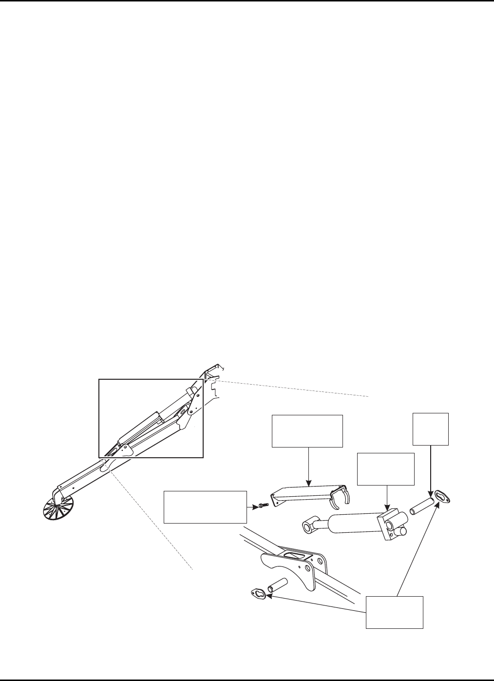
Remove the bolts securing the outrigger cylinder rod
guard (Figure 4-2). Remove the guard.
At the piston rod end of the cylinder, unbolt and
remove the retainer plate from each side of the pivot
pin.
Place a block of wood shoring between the outrigger
beam and cylinder.
Remove the pivot pin using a hammer and a brass or
hardwood drift.
Fully retract the cylinder.
Turn key to the off position and remove the key.
Tag and number all hydraulic hoses that attach to the
cylinder valve block. Use a marker to label the valve
block ports with the appropriate hose numbers.
Unplug the cylinder valve solenoid.
Place absorbent cloths below the cylinder ports and
detach hydraulic hoses from the cylinder. Elevate
hoses to prevent leakage. Plug or cap exposed hose
fittings and cylinder ports.
At the base of the cylinder, unbolt and remove
retainer plate from each side of the pivot pin.
Remove the pivot pin using a hammer and a brass or
hardwood drift.
Lift and remove the cylinder using an overhead hoist
and lifting straps.
Replace or reinstall the cylinder by following the
above instructions in the reverse order of removal.
Actuate the hydraulic system and check for leakage.
Tighten hydraulic fittings as needed.
Bleed trapped air from the hydraulic system by raising
and lowering the boom with the reservoir fill port cap
on but not tightened. Allow several minutes for
trapped air to escape. Repeat as needed.
CYLINDER
CYLINDER ROD
GUARD PIN
CYLINDER ROD
GUARD BOLTS
RETAINING
PLATES
Figure 4-2. Outrigger Cylinder Replacement

BIL-JAX 36XT
28

29
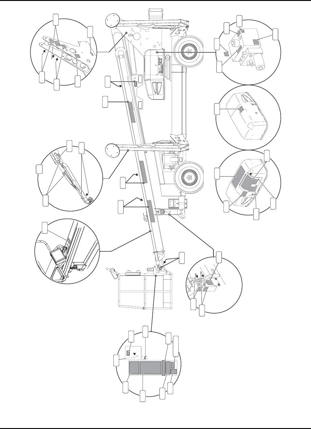
5 REPLACEMENT DECALS
Decals contain information that is required for the safe and proper use of
the aerial work platform. Decals should be considered necessary
components of the machine and should be checked before each use to
verify that they are correctly attached and legible.
Use the following guides to find the correct location of all decals.

BIL-JAX 36XT
30
Table 5-1. Decal Descriptions
Decal No. Decal Description Qty
0202-0523 Made in USA 1
B06-00-0034 DANGER: Electric Shock 1
B06-00-0037 Lubricate Semi-Annually 1
B06-00-0062 NOTICE: AC Power 2
B06-00-0068 NOTICE: Hydraulic System Oil 1
B06-00-0161B Bil-Jax Logo, Black Transfer 2
B06-00-0404 WARNING: Outrigger Crush Toe 8
B06-00-0405 WARNING: Pinch Point 14
B06-00-0471 DANGER: Before Use/Main
Instruction/Hazards (Platform) 1
B06-00-0473 NOTICE: Operator’s Manual
Missing 1
B06-00-0474 NOTICE: Max. Load 1
B06-00-0475 WARNING: Read/Understand
Operator’s Manual 1
B06-00-0476 NOTICE: Range of Motion 2
B06-00-0477 WARNING: Forklift Pockets 2
B06-00-0481 CAUTION: Transport Safety Latch 1
B06-00-0482 DANGER: Electrocution Hazard 2
Decal No. Decal Description Qty
B06-00-0484 DANGER: Battery/Charger Safety 1
B06-00-0494 NOTICE: Hazardous Materials 1
B06-00-0495 CAUTION: Compartment Access
Restricted 2
B06-00-0503 NOTICE: Handle Applications 1
B06-00-0504 NOTICE: Emergency Hand Pump 1
B06-00-0505 DANGER: Before Use/Main
Instruction/Hazards (ground) 1
B06-00-0506 NOTICE: Emergency Lowering 2
B06-00-0521 DANGER: Tip Over Hazard 5
B06-00-0541 CAUTION: Manual Boom
Functions 1
B06-00-0545 Bil-Jax Website Transfer 2
B06-00-0552 NOTICE: Fall Protection Attach-
ment points 1
B06-00-0561 WARNING: Operating Instructions
(Ground) 2
B06-00-0562 WARNING: Operating Instructions
(Platform) 1
B06-00-0563 36XT, 6” Black Transfer 2
Identification Plates
B06-00-0490 VIN Plate 1
B06-00-0499 ANSI ID Plate 1
B06-00-0524 Annual Inspection Plate 1
B06-00-0526 Key Tag 1
5 – DECAL PLACEMENT
31
0545
0476
0474
0552
0202-0523
0062
0475
0495
0034
0484
0495
0068
0504
0494
0541
0476
0037
0493
0503
0506
0405
0482
0404
0521
4x
0481
05520405
05520521
0477
0405
0473
0471
0562
0561
0505
0161B
05520405
0563
Figure 5-1. Decal Locations

BIL-JAX 36XT
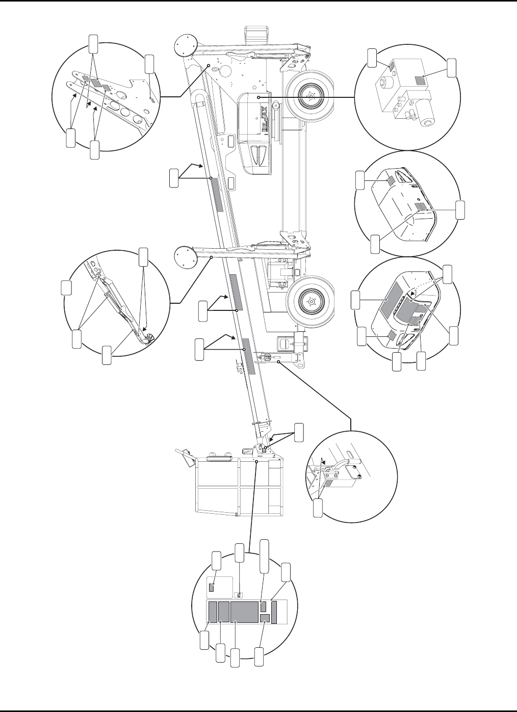
32
Table 5-2. Decal Descriptions – CE
Decal No. Decal Description Qty
0202-0523 Made in USA 1
B06-00-0034 DANGER: Electric Shock 2
B06-00-0037 Lubricate Semi-Annually 1
B06-00-0062 NOTICE: AC Power 2
B06-00-0068 NOTICE: Hydraulic System Oil 1
B06-00-0161B Bil-Jax Logo, Black Transfer 2
B06-00-0173 Fall Protection Attachment Points 1
B06-00-0404 WARNING: Outrigger Crush Toe 8
B06-00-0405 WARNING: Pinch Point 14
B06-00-0471 DANGER: Before Use/Main
Instruction/Hazards (Platform) 1
B06-00-0474 NOTICE: Max. Load 1
B06-00-0475 WARNING: Read/Understand
Operator’s Manual 2
B06-00-0476 NOTICE: Range of Motion 2
Decal No. Decal Description Qty
B06-00-0482 DANGER: Electrocution Hazard 2
B06-00-0495 CAUTION: Compartment Access
Restricted 2
B06-00-0505 DANGER: Before Use/Main
Instruction/Hazards (ground) 1
B06-00-0506 NOTICE: Emergency Lowering 2
B06-00-0541 CAUTION: Manual Boom
Functions 1
B06-00-0545 Bil-Jax Website Transfer 2
B06-00-0561 WARNING: Operating Instructions
(Ground) 2
B06-00-0562 WARNING: Operating Instructions
(Platform) 1
B06-00-0563 36XT, 6” Black Transfer 2
B06-00-0568 WARNING: Outrigger Pressure 4
B06-00-0572 WARNING: Read/Understand
Parts and Service Manual 1
Identification Plates
B06-00-0499-CE CE Serial ID Plate 1
B06-00-0526 Key Tag 1
5 — REPLACEMENT DECALS
33
0563
0545
0476
0474
0173
0202-0523
0062
0475
0495
0034
0495
0068
0541
0476
0037
0506
0405
0482
0405
0404
4x
05520405
0405
0568
0471
0562
0505
0161B
05520405
0561
0475
0572
0034
Figure 5-2. Decal Placement – CE

BIL-JAX 36XT
34

35
6 MATERIAL SAFETY DATA
The following Material Safety Data Sheets describe the correct
procedures for the safe handling of chemical components within the
Model 45XA Articulating Boom Lift, as well as any potential health and
safety hazards related to these chemicals. Material Safety Data Sheets
are included here in accordance with applicable federal and state
regulations. Read and observe all safety precautions. Maintain
awareness of potential health and safety hazards.
MATERIAL SAFETY DATA SHEET
FOR LEAD ACID BATTERIES, WET, FILLED WITH ACID
SECTION I -- GENERAL INFORMATION
Manufacturer’s Name: Crown Battery Mfg. Company EMERGENCY NO: 800 487-2879
Street Address: 1445 Majestic Drive OR 800 OIL-TANK
City, State, Zip Fremont, Ohio 43420
Phone Number: 419 334-7181 REVISION DATE: 5/18/2000
SECTION II -- MATERIAL IDENTIFICATION AND INFORMATION
COMPONENTS PERCENT OSHA ACGIH OTHER LIMITS CAS NUMBER
Hazardous Components PEL TLV
1% or greater
Carcinogens 0.01% or greater
METALLIC LEAD METAL 25.5% 0.05 mg/m3 0.05 mg/m3 NONE 7439-92-1
LEAD SULFATES 18.2% 0.05 mg/m3 0.05 mg/m3 NONE 7439-92-1
LEAD OXIDES 18.0% 0.05 mg/m3 0.05 mg/m3 NONE 7439-92-1
POLYPROPYLENE CASE MTL 6.4%
SEPARATORS 3.5%
SULFURIC ACID (H2SO4) 5.2% 1.0 mg/m3 1.0 mg/m3 NONE 7664-93-9
WATER 19.2%
REGULATORY INFORMATION: Those ingredients listed above are not subject to the reporting requirements of 313
of Title III of the Superfund Amendments and Reauthorization Act. The items are
covered in an exemption as a “Manufactured Article”. 372.30(b)
SECTION III -- PHYSICAL / CHEMICAL CHARACTERISTICS
Boiling Point Approximately 203F Vapor Density: Greater Than 1
Vapor Pressure 14 @ 37% @ 80 F Melting Point: -36 F to -10.6 F
Solubility in Water 100% Water Reactive: Yes, Produces Heat
Specific Gravity 1.245 - 1.295 Battery Electrolyte
Appearance & Odor Clear Liquid with Sharp Pungent Odor
SECTION IV -- FIRE AND EXPLOSION HAZARD DATA
Flash Point: Not Combustible
Auto Ignition Temperature N/A Flammability Limits in Air % by Volume: N/A
Extinguishing Media: Dry Chemical Carbon Dioxide, Water Fog, Water
Special Fire Fighting Procedures: Sulfuric Acid Fumes, Sulfur Dioxide Gas or Carbon Monoxide may be
released when acid decomposes. Wear NIOSH approved self-contained breathing apparatus.
Unusual Hazards: Water applied to sulfuric acid generates heat and causes acid to splatter. Wear full-cover
acid resistant clothing. Sulfuric acid reacts violently with metals, nitrates, chlorates, carbides, fulminates,
picrates and other organic materials. Reacts with most metals to yield explosive/flammable hydrogen gas.
This reaction is intensified when sulfuric acid is diluted with water to form battery electrolyte.

BIL-JAX 36XT
36
MATERIAL SAFETY DATA SHEET
FOR LEAD ACID BATTERIES, WET, FILLED WITH ACID (Continued)
SECTION V -- HEALTH HAZARD DATA
Primary Routes of Entry: Inhalation: YES
Skin: YES
Ingestion: YES
Health Hazards: Acute EYES, SKIN, RESPIRATORY SYSTEM & DIGESTIVE SYSTEM
Chronic: EYES, SKIN, RESPIRATORY SYSTEM & DIGESTIVE SYSTEM
Signs and Symptoms of Exposure: IRRITATION OF EXPOSED AREA, BURNS AND RESPIRATORY PROBLEMS
NO POSSIBILITY OF EXPOSURE OF LEAD WILL OCCUR UNLESS
BATTERY IS DESTROYED.
Medical Conditions Generally
Aggravated By Exposure: EXPOSURE TO MIST MAY CAUSE LUNG DAMAGE & AGGRAVATE
PULMONARY CONDITION.
Emergency First Aid Procedures: SEEK MEDICAL ASSISTANCE FOR FURTHER TREATMENT, OBSERVATION
AND SUPPORT IF NECESSARY.
Eye Contact: WASH WITH COPIOUS QUANTITIES OF COOL WATER FOR AT LEAST 15 MINUTES
Skin Contact: FLUSH AREA WITH LARGE AMOUNTS OF COOL WATER FOR AT LEAST 15 MINUTES
Inhalation: REMOVE TO FRESH AIR, IF BREATHING IS DIFFICULT - GIVE OXYGEN
Ingestion: GIVE MILK TO DRINK, DO NOT INDUCE VOMITTING. CALL PHYSICIAN
SECTION VI -- REACTIVITY DATA
Stability: STABLE Conditions to Avoid: N/A
Incompatibility: AVOID COMBUSTIBLES, ORGANIC MATERIALS, AND STRONG REDUCING AGENTS
Hazardous Decomposition Products: SULFUR TRIOXIDE, CARBON MONOXIDE, SULFURIC ACID FUMES, &
SULFUR DIOXIDE
Hazardous Polymerization: MAY OCCUR Conditions to Avoid: N/A
SECTION VII -- SPILL OR LEAK PROCEDURES
Steps to be taken in case material is released or spilled:
CONTAIN SPILL, USING NON-COMBUSTIBLE MATERIALS: VERMICULITE, DRY SAND & EARTH. NEUTRALIZE
WITH LIME, SODA ASH, SODIUM BICARBONATE, ETC.
Waste disposal method: CONSULT STATE ENVIRONMENTAL AGENCY. INDIVIDUAL STATE REGULATIONS VARY
Precautions to be taken in Handling & Storage: SEPARATE FROM INCOMPATIBLE MATERIALS, KEEP AWAY
FROM FIRE, SPARKS AND HEAT
Other Precautions and/or Special Hazards:
CONTACT WITH METALS MAY PRODUCE TOXIC SULFUR DIOXIDE FUMES & MAY ALSO RELEASE FLAMMABLE
HYDROGEN GAS. THIS REACTION IS INTENSIFIED WHEN DILUTED.
NFPA Rating: HEALTH: 3 FLAMMABILITY: 0 REACTIVITY: 2 SPECIAL: 0
HMIS Rating: HEALTH: 3 FLAMMABILITY: 0 REACTIVITY: 2 PERSONAL PROTECTION: X
SECTION VIII -- CONTROL AND PROTECTIVE MEASURES
Respiratory Protection: ABOVE P.E.L.: NIOSH APPROVED, FITTED, FULL FACE RESPIRATOR
Protective Gloves: ACID RESISTANT
Eye Protection: FULL FACE PROTECTION
Ventilation: LOCAL EXHAUST: VENTILATED AREA PREFERRED
MECHANICAL: IF BELOW P.E.L.
SPECIAL: MUST BE ACID & EXPLOSIVE RESISTANT
OTHER: MUST BE ACID & EXPLOSIVE RESISTANT
Other Protective Equipment: ACID RESISTANT CLOTHING AND BOOTS
Hygienic Work Practices: N/A

6 – MATERIAL SAFETY DATA
37
MATERIAL SAFETY DATA SHEET
DEXRON III/MERCON AUTOMATIC TRANSMISSION FLUID (HYDRAULIC OIL)
SECTION I -- GENERAL INFORMATION
TRADE NAME: CITGO TRANSGARD™ ATF, DEXRON III/MERCON
EMERGENCY TELEPHONE NUMBERS: 918.495.4700 (medical); 800.424.9300 (chemical)
CHEMICAL FAMILY: AUTOMATIC TRANSMISSION FLUID, LUBRICATING OIL
CAS NUMBER: MIXTURE. REVISION DATE: 10/29/98
HAZARDOUS INGREDIENTS: CONTAINS NO INGREDIENTS NOW KNOWN TO BE HAZARDOUS AS
DEFINED IN OSHA 29 CFR 1910.1000 AND OSHA 29 CFR 1910.1200.
SECTION II -- HEALTH HAZARD DATA
PRIMARY ROUTES OF ENTRY: INHALATION, SKIN ABRASION AND INGESTION.
CARCINOGENIC: NO
SYMPTOMS (INGESTION, CONTACT, INHALATION): MILD, TRANSIENT SKIN OR EYE IRRITATION MAY OCCUR.
EYES: FLUSH WITH WATER FOR 15 MINUTES
SKIN: WASH THOROUGHLY WITH WARM SOAPY WATER.
INGESTION: DO NOT INDUCE VOMITTING-SEEK MEDICAL ATTENTION.
CONDITIONS AGGRAVATED BY EXPOSURE: NONE KNOWN
AIR EXPOSURE LIMITS: P.E.L. 5 mg/m3 (OSHA) T.L.V. 10mg/m3 (ACGIH)
HEALTH: 0 FIRE: 1 SPECIFIC: X REACTIVITY: 0
SECTION III -- PHYSICAL DATA
BOILING POINT/FREEZING POINT: N/A
VAPOR PRESSURE (PSIA): N/A
SPECIFIC GRAVITY (H20=1): 0.86
SOLUBILITY IN WATER: NEGLIGIBLE; INSOLUBLE IN COLD WATER
PH OF CONCENTRATE: N/A
APPEARANCE AND ODOR: RED LIQUID, MILD PETROLEUM ODOR
SECTION IV -- FIRE AND EXPLOSION HAZARD DATA
FLASH POINT (METHOD USED): CLOSED: 339º F (Pensky-Martens); OPEN: 390º F (Cleveland).
FLAMMABLE LIMITS: NOT DETERMINED
LEL: N/A UEL: N/A
EXTINGUISHING MEDIA: DRY CHEMICAL, FOAM, CO2, WATER FOG. TREAT AS CLASS B FIRE.
UNUSUAL FIRE AND EXPLOSION HAZARDS: PRODUCES COMBUSTIBLE VAPOR AT TEMPERATURES ABOVE FLASH POINT
SECTION V -- REACTIVITY DATA
STABILITY: STABLE
CONDITIONS TO AVOID: AVOID EXTREMES OF HEAT; IGNITION SOURCES.
INCOMPATIBILITY (MATERIALS TO AVOID): STRONG OXIDIZING MATERIALS.
HAZARDOUS DECOMPOSITION PRODUCTS: INCOMPLETE COMBUSTION MAY CAUSE CARBON OXIDES.
HAZARDOUS POLYMERIZATION: WILL NOT OCCUR.
SECTION VI -- SPECIAL PROTECTION INFORMATION
RESPIRATORY PROTECTION (SPECIFIC TYPE): NONE REQUIRED
VENTILATION: NORMAL
LOCAL EXHAUST: NORMAL
MECHANICAL EXHAUST (GENERAL): X
PROTECTIVE GLOVES: OIL IMPERVIOUS GLOVES RECOMMENDED
EYE PROTECTION: SAFETY GLASSES RECOMMENDED
OTHER PROTECTIVE EQUIPMENT: PROTECTIVE CLOTHING RECOMMENDED
SPECIAL LABELLING INSTRUCTIONS: NOT REQUIRED
SPECIAL PACKAGING RECOMMENDATIONS: NONE
HANDLING AND STORAGE RECOMMENDATIONS: AVOID EXTREMES OF COLD OR HEAT. STORE IN CLEAN DRY AREA.
SPILL OR LEAK PROCEDURES: IN CASE OF LEAK OR SPILL, DIKE AND ABSORB WITH INERT MATERIAL. FOLLOW
ALL LOCAL, STATE AND FEDERAL REGULATIONS FOR DISPOSAL.
DISCLAIMER: THE INFORMATION CONTAINED HEREIN HAS BEEN COMPILED FROM SOURCES
CONSIDERED TO BE DEPENDABLE AND IS ACCURATE TO THE BEST OF THE SELLER’S
KNOWLEDGE. THE SELLER MAKES NO WARRANTY WHATSOEVER, EXPRESSED OR IMPLIED, REGARDING THE ACCURACY
OF SUCH DATA OR THE RESULTS TO BE OBTAINED FROM THE USE THEREOF.

38

39
APPENDIX:REPLACEMENT PARTS
Use only parts manufactured and/or authorized by Bil-Jax, Inc. when replacing
damaged components. See page 89 for replacement part ordering information.
Only personnel properly trained and authorized to operate all equipment and
familiar with all boom functions should attempt to repair or replace any part of the
boom lift.
Always read, understand and obey all safety precautions included in this
manual, as well as those precautions attached to the lift and dictated by
federal, state and local regulations.

40
Assembly Description Page
Outrigger 42
Engine 44
Front Rest 48
Front Axle 50
Rear Axle 52
Slew Ring 54
Counterweight 56
Control Compartment 58
Pump Compartment 60
Battery Compartment 62
Cover 64
Boom 66
Cable Track 70
Boom Nose 72
Platform 74
Hydraulic Pump 76

41
Assembly Description Page
Boom and Rotation Hydraulic Lines 80
Outrigger Hydraulic Lines 82
Trailer Hydraulic Lines – 4WD 83
Wire Harnesses 86
Manifold Wire Harness 87
Gas Engine Wire Harness 87
Choke/Throttle Solenoid Wire Harness 88
Engine Relays Wire Harness 88
ATC Fuse Holder 89
Start/Stop/Run Wire Harness 89
Generator Switcher Box 90
Wire Assembly – Fan 90
IEC Cord – Male – US Markets 91
Generator 110V Wire Harness 91
Oil Switch 91
Cord Assembly – 110V Generator 92
Cord Assembly – Generator Switch 92
Cord Assembly – Switch Jumper 92
Cord Assembly – 110V AC Plug – Female 92
Switcher Box – CE Models 93
220V Generator Wire Harness – CE Models 93
Cord Assembly – 220V AC Plug – Female – CE Models 93
Pump And Cylinder Wire Harnesses 94
Outrigger Coil and Switches Wire Harness 95
Analog Harness 96
Power Harness 96
110 VAC Tower-Platform Harness 96
Platform-Ground Communication Cable 97
Material Hook 98
Battery Layout 100
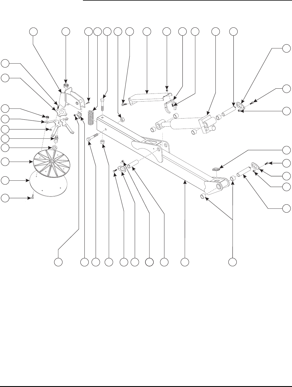
42
OUTRIGGER ASSEMBLY
1
2
3
4
5
6
8
10
11 12 13
14
15
19
20
21
22
23
24
25
26
28 4
5
5
6
6
7
7
7
17
18 16
17
9
27
13
14
14
29
30

43
OUTRIGGER ASSEMBLY PARTS LIST
Item No. Part No. Description Qty.
1 A-00120 Outrigger Weldment 1*
2 A-00046 Grommet – 1.5 x 1.25 x 1.75 1
3 A-00032 Bearing 2
4 A-00020 Pin, 1.25 x 5.5 2
5 A-00019 Pin Retainer, 1.25 3
6 0096-0016 Cap Screw, M10 x 25 3
7 0096-0041 Hex Nut, Self-Locking, M10 3
8 A-00060 Pin, 1.25 x 4.25 1
9 A-00138 Outrigger Hydraulic Cylinder 1
10 A-00141 Outrigger Cylinder Guard 1
11 0096-0009 Cap Screw, M8 x 10 2
12 A-00142 Guard Slide 1
13 0096-0010 Cap Screw, M8 x 20 6
14 0096-0040 Hex Nut, Self-Locking, M8 10
15 A-00154 Spring, Outrigger Sensor 1
16 0096-0036 Cap Screw, M16 x 150 1
17 0096-0044 Hex Nut, Self-Locking, M16 2
18 A-00128 Pad Mount Weldment 1
19 0096-0051 Cap Screw, M16 x 100 1
20 B01-03-0078 Limit Switch Assembly 1
21 0090-0232 Slotted Machine Screw, #10-24 x 5/8 2
22 0090-0182 Hex Nut, Self-Locking, #10-24 2
23 A-00136 Foot Pad, Aluminum, 12” 1
24 A-00137 Foot Pad Bottom, 12” 1
25 0096-0121 Flat Head Cap Screw, M8 x 30 4
26 A-00135 Foot Pad Ball 1
27 A-00195 O-Ring, 1 1/4” OD x 1” ID 1
28 0096-0045 Hex Nut, Self-Locking, M20 1
29 A-00127 Foot Pad Lock 2
30 A-00139 Foot Pad Lock Cap 1
*Quantities listed reflect the number of parts needed for each outrigger.
NOTE: Unless otherwise noted, high-strength Grade 5/Class 8.8 fasteners
are used in the assembly of this equipment.
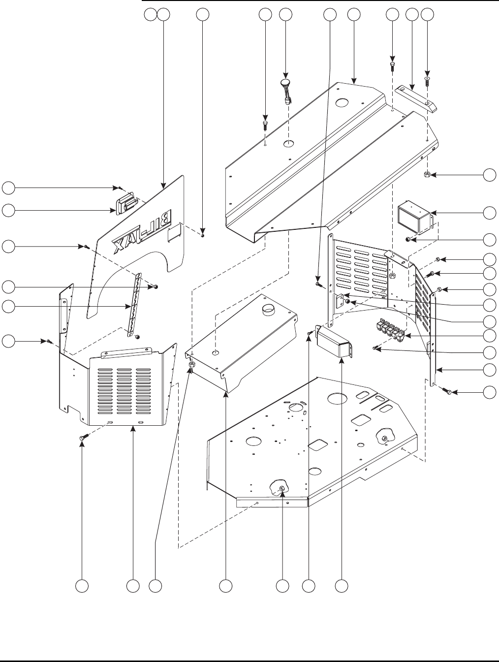
44
ENGINE ASSEMBLY (I)
1
2
3
4
56
78
9
10
11
12
14
15
16 17
18
19
20
21
22
23
24
25
7
8
8
8
15
15
3
2
13
3
2

45
ENGINE ASSEMBLY (I) PARTS LIST
Item No. Part No. Description Qty.
1 A-01063 Cover Front 1
2 0096-0014 Cap Screw, M10 x 20 14
3 0096-0041 Hex Nut, Self-Locking, M10 22
4 A-01064 Cover Top 1
5 A-01067 Cover Side – Left 1
6 A-01069 Cover Side – Right 1
7 0096-0001 Cap Screw, M6 x 16 20
8 0096-0039 Hex Nut, Self-Locking, M6 33
9 B42-01-1006 Hinge – 72” Continuous 2
10 A-01045 Latch, Paddle-Style 2
11 0096-0113 Cap Screw, M4 x 16 8
12 0096-0073 Hex Nut, Self-Locking, M4 8
13 A-01052 Cover Rear 1
14 B01-06-0053 Relay 24V DC w/ Bracket 5
15 0096-0002 Cap Screw, M6 x 20 13
16 A-A-01059 Cover Pad 2
17 0096-0068 Flat Head Cap Screw, M10 x 45 4
18 A-03048 Relay Cover 1
19 A-03040 Switcher Box Assembly 1
B01-06-0056 Relay – 30 Amp 1
B01-10-0354 Circuit Breaker – 20 Amp 1
A-01015 Switcher Box 1
20 A-01072 Cover Latch Stop 2
21 0096-0098 Cap Screw, M8 x 35 4
22 0096-0040 Hex Nut, Self-Locking, M8 4
23 A-01047 Fuel Tank 1
24 A-01089 Fuel Gauge 1
25 0096-0016 Cap Screw, M10 x 25 2
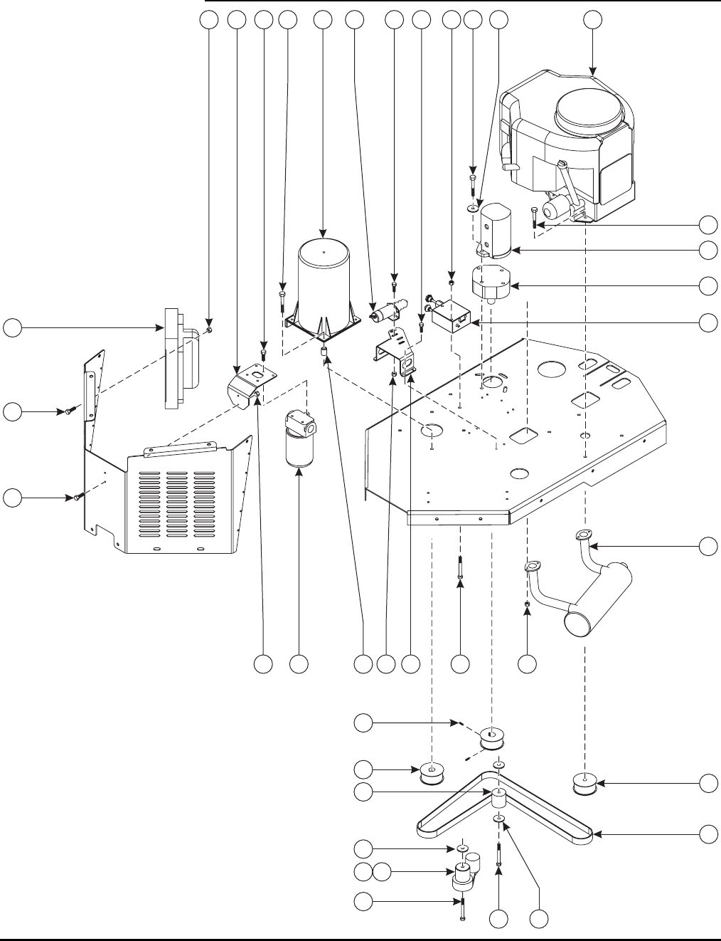
46
ENGINE ASSEMBLY (II)
1
2
3
4
5
67
9
10
26
11
12
13
14
15
16
17
18
1920
21
22
23
24
25
12 1212 3
13 3
28 29
27
33
31 32
34

47
ENGINE ASSEMBLY (II) PARTS LIST
Item No. Part No. Description Qty.
1 A-01046 Engine 21HP (See Manufacturer’s Literature) 1
2 0096-0098 Cap Screw, M8 x 35 4
3 0096-0040 Hex Nut, Self-Locking, M8 18
4 A-01048 Pump – Dual – 4.5 GPM 1
5 A-01055 Dual Pump Mount 1
6 0096-0110 Cap Screw, M10 x 110 2
7 0096-0093 Washer, M10 2
8 0096-0041 Hex Nut, Self-Locking, M10 2
9 A-01081 Oil Cooler 1
10 0096-0010 Cap Screw, M8 x 20 4
11 A-01071 Solenoid Bracket 1
12 0096-0001 Cap Screw, M6 x 16 12
13 0096-0039 Hex Nut, Self-Locking, M6 10
14 A-01074 Throttle Solenoid Assembly 2
15 A-00761 Generator 1
16 A-01060 Spacer 4
17 0096-0053 Cap Screw, M8 x 50 4
18 A-01038 Brake Release – Hand Pump 1
19 0096-0108 Cap Screw, M8 x 70 2
20 B02-00-0071 Oil Filter Assembly 1
21 B29-00-0016 Oil Filter Bracket 1
22 A-00783 Exhaust Assembly 1
23 A-01061 Belt 1
24 A-01051 Pulley 2
25 0090-0363 Set Screw – 1/4 - 20 x 3/4 6
26 A-01036 Pulley 1
27 A-01088 Idler Roller 1
28 0096-0022 Cap Screw, M12 x 75 1
29 0096-0076 Washer, M12 3
30 0096-0041 Hex Nut, Self-Locking, M12 1
31 A-01095 Tension Arm 1
32 A-01086 Spacer – Tension Arm 1
33 0090-0210 Washer – 3/8” 1
34 0096-0069 Cap Screw, M10 x 75 1
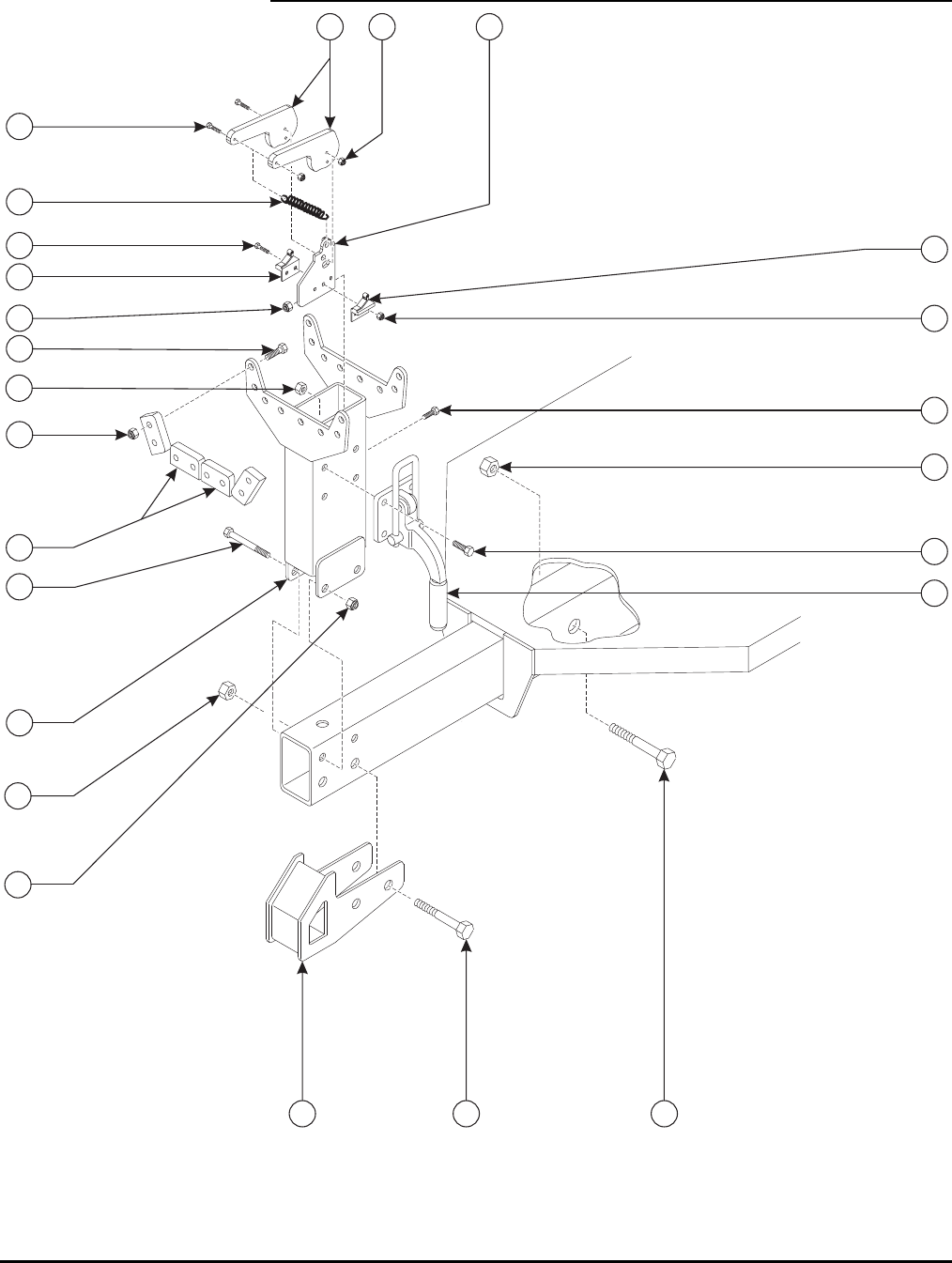
48
FRONT REST ASSEMBLY
1
2
3
4
5
6
7
8
9
10
11
12
13
14
16
17
18
19
20
21
6
15
20
22
21

49
FRONT REST ASSEMBLY PARTS LIST
Item No. Part No. Description Qty.
1 A-03145 Front Rest Weldment 1
2 0096-0024 Cap Screw, M12 x 100 2
3 0096-0042 Hex Nut, Self-Locking, M12 2
4 A-00157 Front Rest Pad 6
5 0096-0017 Cap Screw, M10 x 30 16
6 0096-0041 Hex Nut, Self-Locking, M10 20
7 A-00159 Boom Latch 1
8 0096-0016 Cap Screw, M10 x 25 4
9 A-00169 Switch Bracket 1
10 0096-0002 Cap Screw, M6 x 20 2
11 0096-0039 Hex Nut, Self-Locking, M6 2
12 A-00188 Switch Cam 2
13 0090-1104 Machine Screw, #4-40 x 1 3
14 0090-0525 Hex Nut, Self-Locking, #4-40 3
15 B01-03-0078 Limit Switch Assembly, NO (Female) 1
16 B01-03-0079 Limit Switch Assembly, NC (Male) 1
17 0090-0709 Machine Screw, #6-32 x 1 1/4 2
18 0090-0180 Hex Nut, Self-Locking, #6-32 2
19 A-00158 Tension Spring 1
20 0096-0038 Cap Screw, M20 x 120 4
21 0096-0045 Hex Nut, Self-Locking, M20 4
22 A-01082 Tie Weldment – 4WD 1
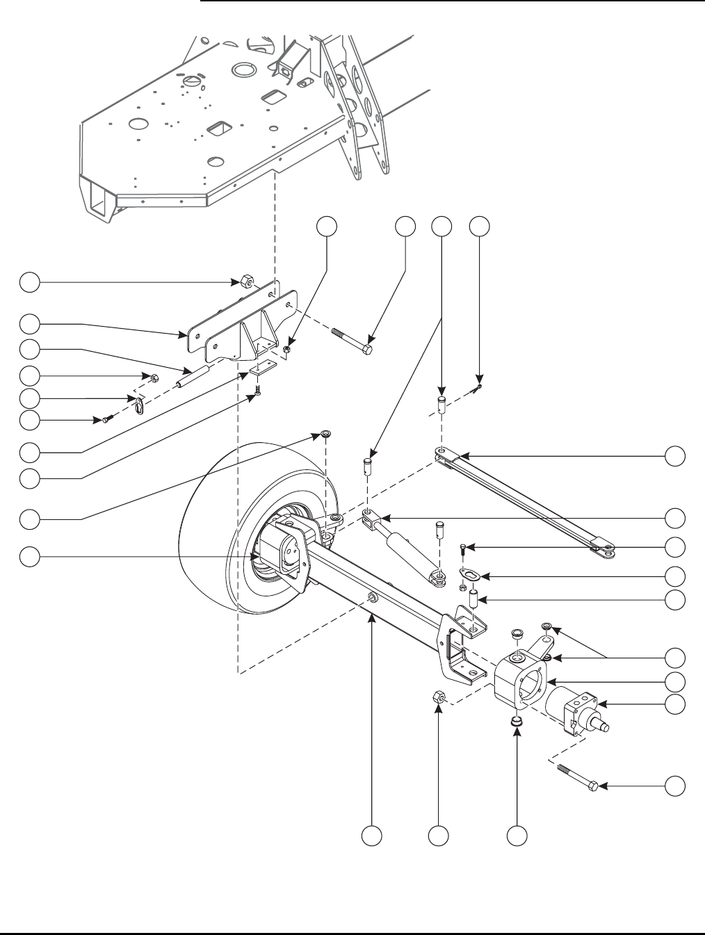
50
FRONT AXLE ASSEMBLY
12
3
4
5
6
7
8
9
20
10
11
12
13
14 15
16
17
18
19
21
22
23
24
8
13

51
FRONT AXLE ASSEMBLY PARTS LIST
Item No. Part No. Description Qty.
1 A-01010 Front Axle Weldment – 4WD 1
2 A-01097 Bushing, 1.5” OD x 1.25” ID 4
3 A-01020 Front Yoke – Left 1
4 A-01021 Front Yoke – Right 1
5 A-01070 Pin – 1.25” x 1.625” 4
6 A-00019 Pin Retainer – 1.25” 4
7 0096-0016 Cap Screw, M10 x 25 4
8 0096-0041 Hex Nut, Self-Locking, M10 9
9 A-01022 Hydraulic Motor – 4WD 2
10 0096-0024 Cap Screw, M12 x 100 8
11 0096-0042 Hex Nut, Self-Locking, M12 8
12 A-01025 Tie Rod – 4WD 1
13 A-01096 Bushing, 1.25” OD x 1.0” ID 4
14 A-01085 Pin – Front Axle 4
15 0090-0155 Cotter Pin – 3/16” x 1 3/4" 4
16 A-01030 Steering Cylinder – 4WD 1
17 A-01005 Front Axle Mount Weldment 1
18 0096-0038 Cap Screw, M20 x 120 2
19 0096-0045 Hex Nut, Self-Locking, M20 2
20 A-01029 Pad – Front Axle 2
21 0096-0091 Flat Head Cap Screw, M10 x 25 4
22 A-01009 Pin – 1.0” x 5.5” 1
23 A-00018 Pin Retainer – 1.0” 1
24 0096-0014 Cap Screw, M10 x 20 1
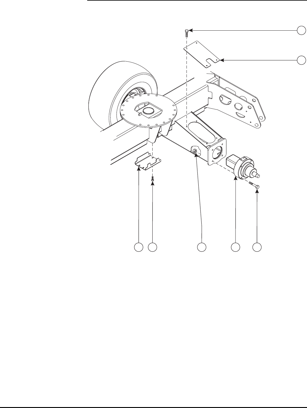
52
REAR AXLE ASSEMBLY
12 45
6
7
2

53
REAR AXLE ASSEMBLY PARTS LIST
Item No. Part No. Description Qty.
1 A-00175 Hydraulic Cover 1
2 0096-0010 Cap Screw, M8 x 20 12
3 0096-0067 Clip Nut, M8 12
4 A-01032 Hydraulic Motor – Rear 2
5 0096-0024 Cap Screw, M12 x 100 8
6 0096-0042 Hex Nut, Self-Locking, M12 8
7 A-01037 Axle Cover 2
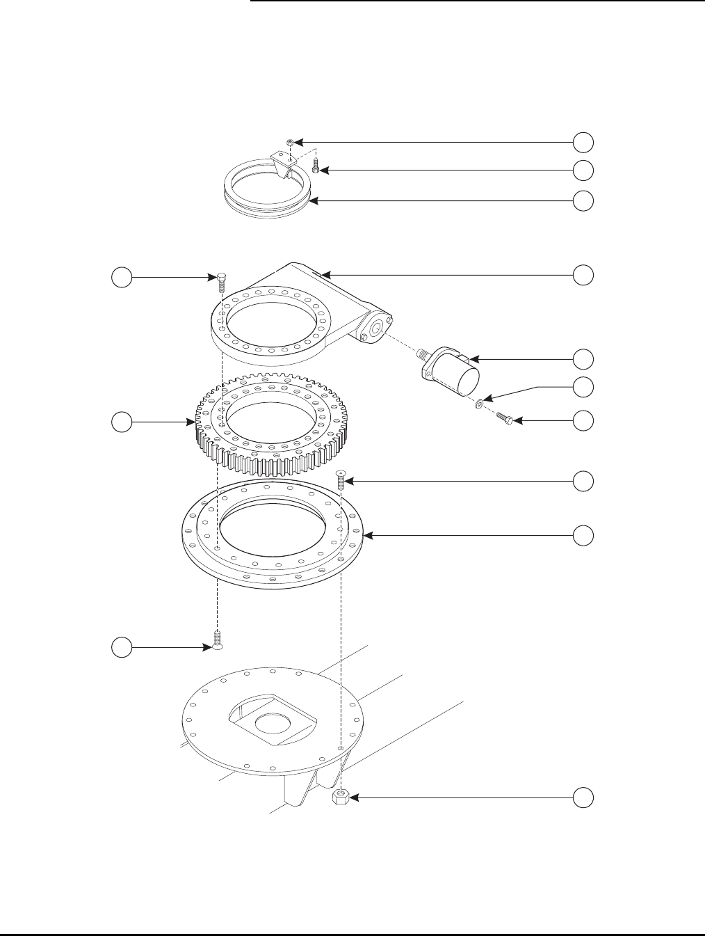
54
SLEW RING ASSEMBLY
3
1
25
6
7
8
9
10
11
12
13
4

55
SLEW RING ASSEMBLY PARTS LIST
Item No. Part No. Description Qty.
1 A-02189 Slew Assembly and Adapter 1
2 Slew Ring 1
3 Slew Ring Drive 1
4 A-00149 Base Ring Adapter 1
5 0090-0461 Cap Screw, 1/2-13 x 2 2
6 0090-0212 Lock Washer, 1/2 2
7 0096-0033 Flat Head Cap Screw, M16 x 35 16
8 0096-0054 Flat Head Cap Screw, M16 x 50 18
9 0090-0643 Cap Screw, 5/8-11 x 2-3/4, Grade 8 19
10 0096-0044 Hex Nut, Self-Locking, M16 16
11 A-00350 Rotation Stop Assembly 1
12 0096-0021 Cap Screw, M12 x 45 2
13 0096-0042 Hex Nut, Self-Locking, M12 2
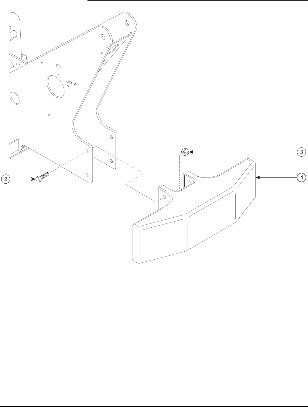
56
COUNTERWEIGHT ASSEMBLY

57
COUNTERWEIGHT ASSEMBLY PARTS LIST
Item No. Part No. Description Qty.
1 A-00270 Counterweight 1
2 0096-0065 Cap Screw, M20 x 80 4
3 0096-0045 Hex Nut, Self-Locking, M20 4
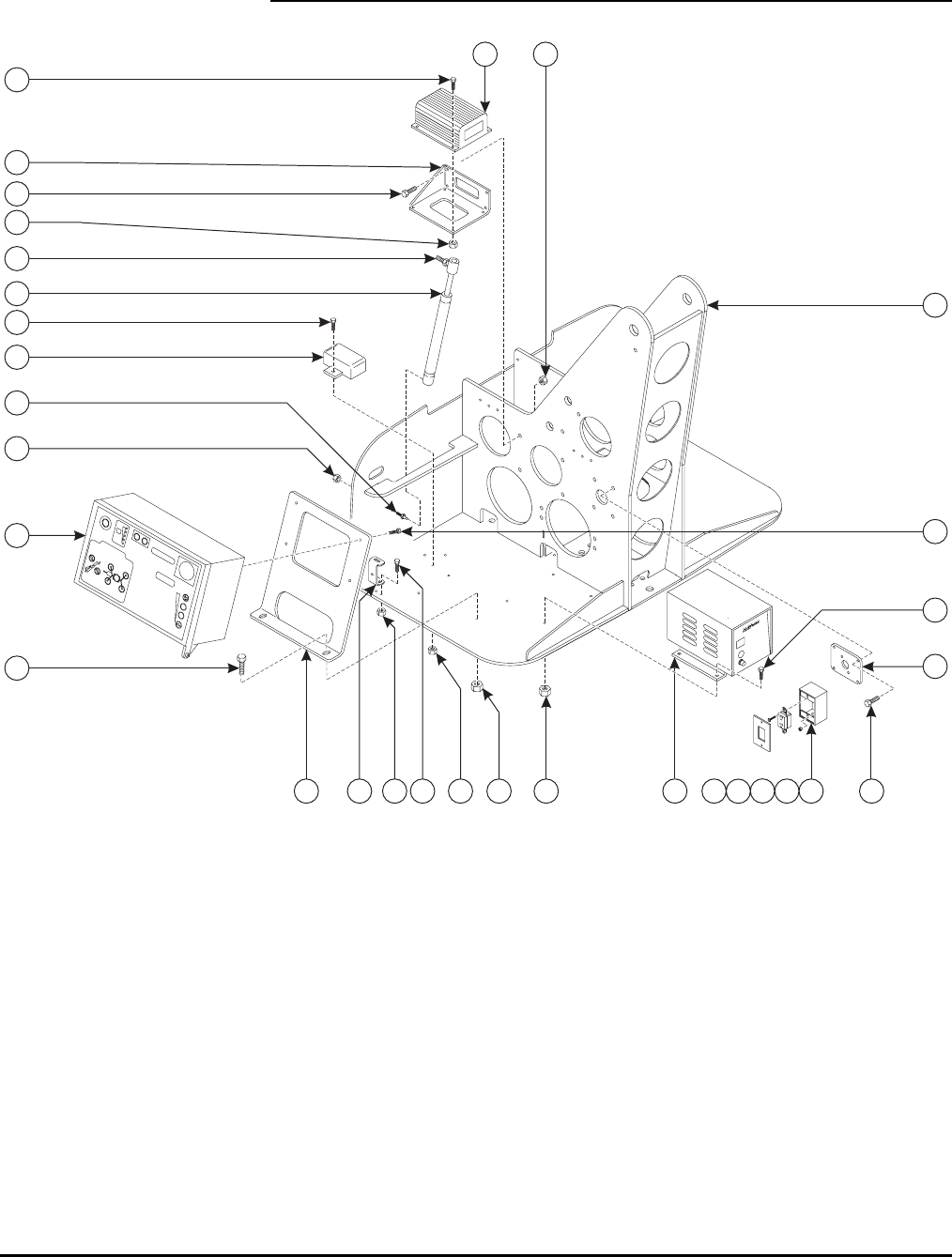
58
CONTROL COMPARTMENT ASSEMBLY
1
3
4
25
6
7
8
9
10
11
12
13
14
15
7
13
8 7 17 18 19 2016
7
7
8
8
21
21
8
22

59
CONTROL COMPARTMENT ASSEMBLY PARTS LIST
Item No. Part No. Description Qty.
1 A-00712 Lower Control Box 1
2 A-00233 Lower Control Mount 1
3 A-00290 Cover Stop Bracket 1
4 0096-0016 Cap Screw, M10 x 25 2
5 0096-0041 Hex Nut, Self-Locking, M10 2
6 A-00295 Level Sensor 1
7 0096-0002 Cap Screw, M6 x 20 16
8 0096-0039 Hex Nut, Self-Locking, M6 20
9 A-00287 Mount Plate – GFI Outlet 1
10 A-00255 Motor Controller 2
11 B01-05-0056 Battery Charger 1
12 A-00274 Gas Spring 1
13 0090-0920 Stud Ball, 10mm 2
14 0090-0185 Hex Nut, Self-Locking, 5/16-18 2
15 A-03200 Turntable Weldment 1
16 B01-10-0046 Outlet Box 1
17 B01-10-0034 GFI Outlet 1
18 B01-10-0035 Outlet Box Cover 1
19 0096-0001 Cap Screw, M6 x 16 2
20 A-00288 Plastic Cover 1
21 0096-0004 Cap Screw, M6 x 25 8
22 A-00935 Dual Motor Controller Bracket 1
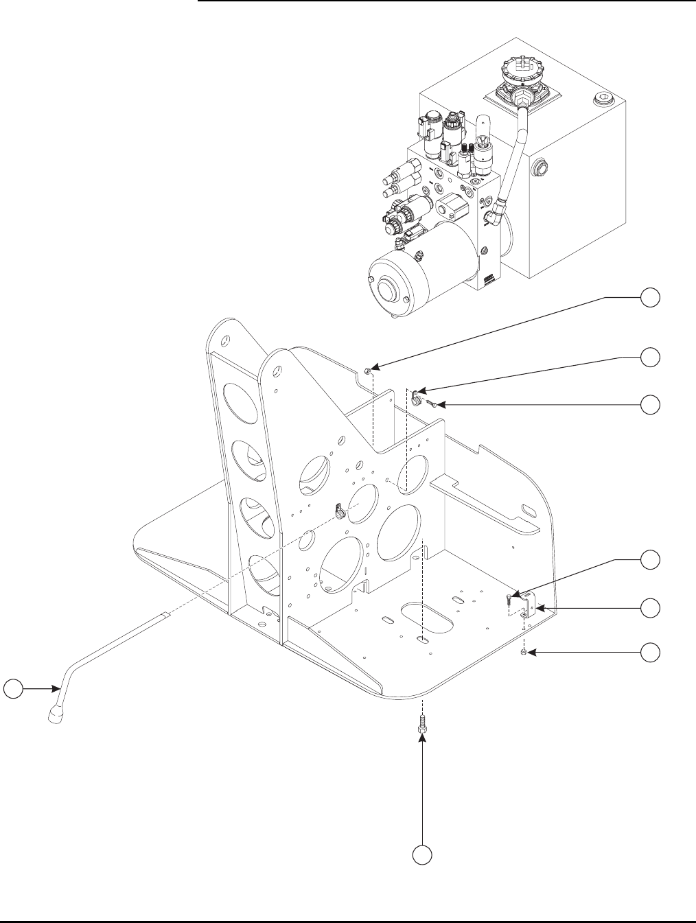
60
PUMP COMPARTMENT ASSEMBLY
1
2
3
4
5
6
7
4

61
PUMP COMPARTMENT PARTS LIST
Item No. Part No. Description Qty.
1 A-00268 Tire Iron/Jack Handle 1
2 B04-07-0033 Clamp 2
3 0096-0001 Cap Screw, M6 x 16 2
4 0096-0039 Hex Nut, Self-Locking, M6 4
5 A-00290 Cover Stop Bracket 1
6 0096-0002 Cap Screw, M6 x 20 2
7 0096-0014 Cap Screw, M10 x 20 2
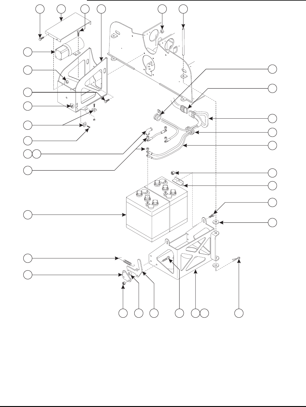
62
BATTERY COMPARTMENT ASSEMBLY
1
3
4
5
6
7
11
14
17
2
89
10
13
12
8
22
24
23
21
25
20
26 27
29
28
16
16
17
15
19
18
30
16

63
BATTERY COMPARTMENT ASSEMBLY PARTS LIST
Item No. Part No. Description Qty.
1 A-00215 Battery Box Weldment – Left 1
2 A-00220 Battery Box Weldment – Right 1
3 A-00278 Battery Hinge Pin 2
4 0096-0050 Washer, Flat, M16 8
5 0090-0147 Cotter Pin 4
6 A-00271 Battery Clamp 4
7 0096-0010 Cap Screw, M8 x 20 4
8 0096-0040 Hex Nut, Self-Locking, M8 8
9 A-00219 Battery Box Latch 2
10 A-00256 Motor Cover 1
11 A-00229 Latch Plate 2
12 A-00234 Spacer 2
13 0096-0011 Cap Screw, M8 x 25 6
14 A-00244 Tension Spring 2
15 A-00225 Nose Weldment 1
16 0096-0014 Cap Screw, M10 x 20 10
17 0096-0041 Hex Nut, Self-Locking, M10 10
18 A-00037 Ramp, Short 4
19 0096-0002 Flat Head Cap Screw, M6 x 20 4
20 0096-0039 Hex Nut, Self-Locking, M6 4
21 A-00046 Grommet 4
22 B04-07-0036 Clamp 2
23 B01-09-0132 A-Frame Handle, Connector 1
24 B01-09-0131 Plug, Connector 1
25 A-03272 Battery Cable Kit 1
26 B01-09-0133 Terminal Boot – Black 4
27 B01-09-0134 Terminal Boot – Red 4
28 A-00242 Battery 4
29 0090-0162 Hex Nut, 3/8-16” 8
30 A-00235 Power Unit, 4WD 1
B02-15-0528 3KW 24V DC Motor 1
B02-15-0529 Gear Pump 2.0 ccm 1
B02-02-0301 Fitting M14 x –6 ORFS 1
B02-02-0302 Fitting, M18 x –8 ORFS 1
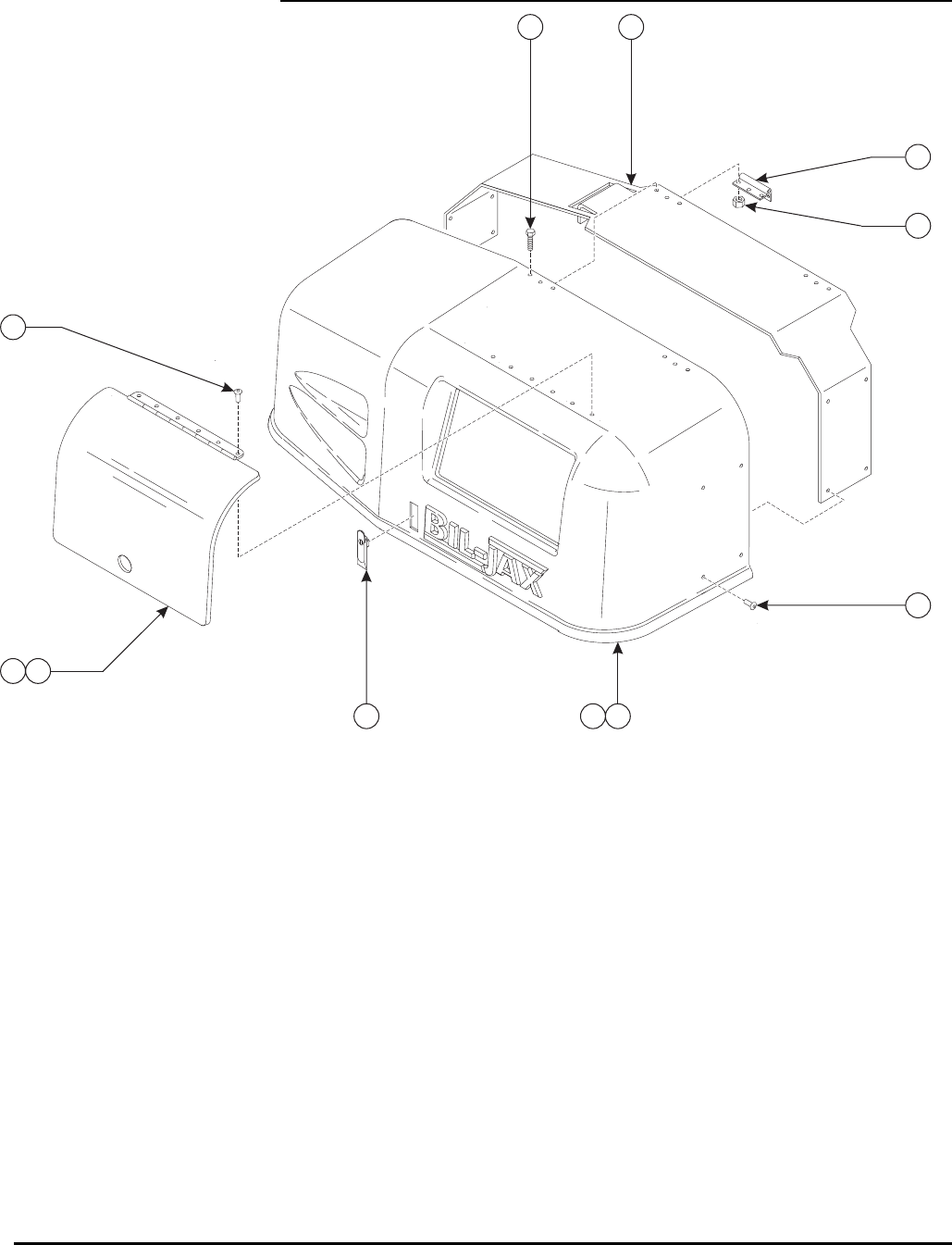
64
COVER ASSEMBLY
12
3
4
5
6
7
89
10
7

65
COVER ASSEMBLY PARTS LIST
Item No. Part No. Description Qty.
1 A-03240 Cover – Left 1
2 A-03239 Cover – Right 1
3 A-00228 Cover Brace 2
4 A-00252 Hinge 4
5 0096-0002 Cap Screw, M6 x 20 12
6 0096-0039 Hex Nut, Self-Locking, M6 12
7 0090-1080 Pop Rivet 22
8 A-00258 Controls Cover – Left Side 1
9 B42-01-1002 Hinge, Controls Cover 1
10 A-00292 Cover Latch Assembly 2
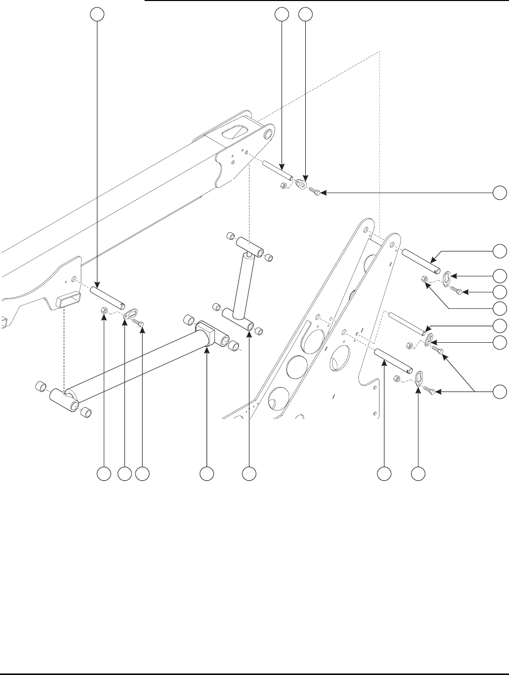
66
BOOM ASSEMBLY (I)
1
2
3
4
5
6
789
10
8
9
9
4
4
3
5
4

67
BOOM ASSEMBLY PARTS LIST
Item No. Part No. Description Qty.
1 A-00552 Hydraulic Master Cylinder 1
2 A-00024 Pin, .75 x 8.5 1
3 A-00017 Pin Retainer – .75 2
4 0096-0016 Cap Screw, M10 x 25 7
5 0096-0041 Hex Nut, Self-Locking, M10 7
6 A-00026 Pin, .75 x 7.0 1
7 A-00551 Hydraulic Boom Cylinder 1
8 A-00021 Pin, 1.25 x 8.5 2
9 A-00019 Pin Retainer – 1.25 5
10 A-00023 Pin, 1.25 x 7.25 1
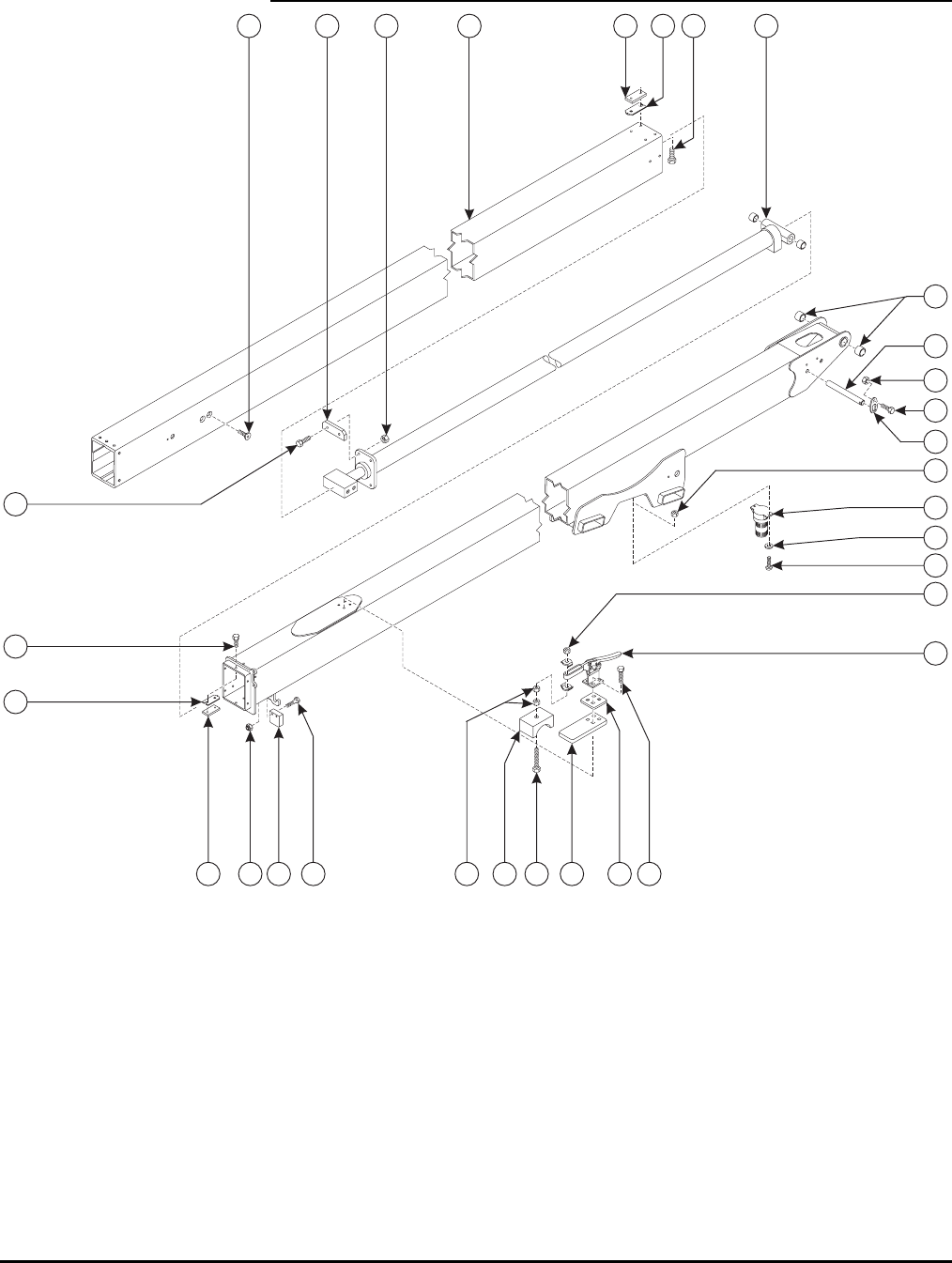
68
BOOM ASSEMBLY (II)
12
3
4
5
6
7
8
9
10
11
12
13
14
15 16
17 18 19 20
21
22
23
24
25
26
27
24
14
13
5
28

69
BOOM ASSEMBLY PARTS LIST
Item No. Part No. Description Qty.
1 A-00510 Telescopic Boom Tube 1
2 A-00550 Hydraulic Extension Cylinder 1
3 A-00535 Slider 2
4 0096-0018 Cap Screw, M10 x 40 4
5 0096-0041 Hex Nut, Self-Locking, M10
6 A-00032 Bearing 2
7 0096-0033 Flat Head Cap Screw, M16 x 35 4
8 A-00027 Pin, .75 x 7.0 1
9 A-00017 Retainer – .75 1
10 0096-0016 Cap Screw, M10 x 25 1
11 A-00533-1 Wear Pad – Green 5
12 A-00533-2 Wear Pad – Grey 7
13 A-00534 Wear Pad Shim 6
14 0096-0013 Nylon Cap Screw, M10 x 16 24
15 A-00537 Boom Switch Block 1
16 0096-0098 Cap Screw, M8 x 35 2
17 0096-0040 Hex Nut, Self-Locking, M8 2
18 A-00469 Cage Latch Pad 1
19 A-00470 Cage Storage Pad 1
20 A-00471 Cage Latch Plate 1
21 A-00473 Cage Latch 1
22 0096-0001 Cap Screw, M6 x 16 4
23 0096-0049 Cap Screw, M8 x 50 1
24 0096-0040 Hex Nut, Self-Locking, M8 3
25 B01-10-0275 Strobe Light (Option) 1
26 0090-0236 Machine Screw, #10-24 x 3/4 2
27 0090-0415 Washer, Flat, #10 2
28 0090-0182 Hex Nut, Self-Locking, #10-24 2
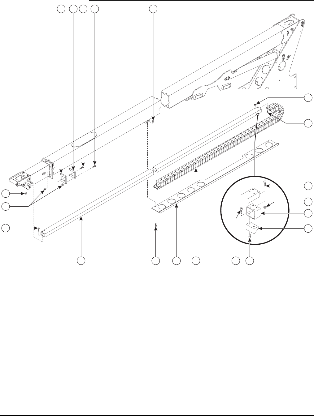
70
CABLE TRACK ASSEMBLY
1
2
3
4567
8
910
11
13
12
14
2
2
3
3
3
8

71
CABLE TRACK ASSEMBLY PARTS LIST
Item No. Part No. Description Qty.
1 A-00531 Slide Tube 1
2 0096-0010 Cap Screw, M8 x 20 16
3 0096-0040 Hex Nut, Self-Locking, M8 18
4 A-00532 Tube Slider 1
5 A-00529 Tube Slider Back 1
6 0096-0018 Cap Screw, M10 x 40 2
7 0096-0017 Cap Screw, M10 x 30 2
8 0096-0041 Hex Nut, Self-Locking, M10 8
9 B00-00-0031 Cable Track – 41 Links 1
10 A-00536 Cable Track Tray 1
11 0096-0014 Cap Screw, M10 x 20 4
12 A-00538 Cable Support Tube 1
13 A-00539 Cable Slide Block 1
14 0096-0056 Cap Screw, M8 x 30 2

72
BOOM NOSE ASSEMBLY
1
2
3
4
5
67
8
910 1112
13
14
15
16
17
18
19 20
21 22
23
24
25 26
27
28
29
30
31
8
13
2

73
BOOM NOSE ASSEMBLY PARTS LIST
Item No. Part No. Description Qty.
1 A-00979 Bulkhead Mount 1
2 0096-0016 Cap Screw, M10 x 25 4
3 A-00601 Platform Pivot Weldment 1
4 A-00025 Pin, 1.0 x 6.5 1
5 A-00018 Pin Retainer – 1.0 1
6 0096-0041 Hex Nut, Self-Locking, M10 6
7 0096-0015 Socket Head Cap Screw, M10 x 20 2
8 A-00033 Bearing 4
9 A-00606 Snap Pin 2
10 A-00608 Compression Spring 1
11 A-00609 Knob, Platform Latch 2
12 0096-0055 Cap Screw, M12 x 190 1
13 0096-0042 Hex Nut, Self-Locking, M12 10
14 A-00553 Hydraulic Slave Cylinder 1
15 A-00027 Pin, .75 x 5.25 DB 1
16 A-00034 Pin Retainer – .75 FH 2
17 0096-0012 Flat Head Cap Screw, M8 x 25 2
18 0096-0040 Hex Nut, Self-Locking, M8 2
19 A-00035 Pin, .75 x 6.5 1
20 A-00017 Pin Retainer – .75 1
21 A-00522 Boom End Weldment 1
22 0096-0020 Cap Screw, M12 x 30 9
23 A-00031 Bearing 2
24 A-00610 Platform Mount Weldment 1
25 A-00038 Ramp 4
26 0096-0003 Flat Head Cap Screw, M6 x 20 8
27 0096-0039 Hex Nut, Self-Locking, M6 10
28 B01-10-0046 Outlet Box 1
29 B01-10-0034 GFI Outlet 1
30 B01-10-0035 Outlet Box Cover 1
31 0096-0001 Cap Screw, M6 x 16 2
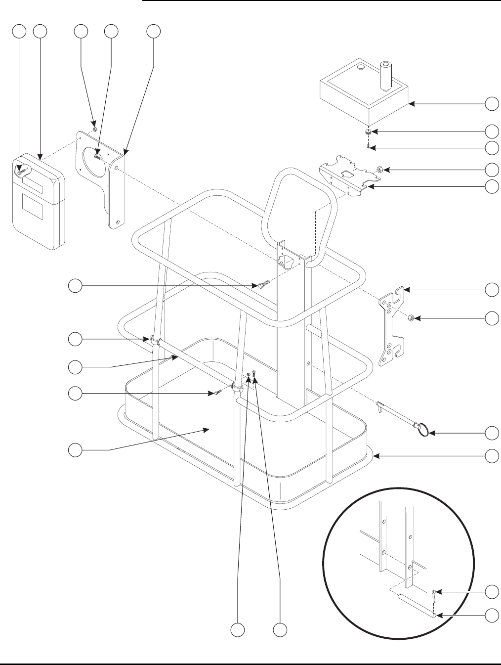
74
PLATFORM ASSEMBLY
1
2
5
6
7
9
10
11
12
13 14
1516
17
18
19
20
21
22
24
13
7
23

75
PLATFORM ASSEMBLY PARTS LIST
Item No. Part No. Description Qty.
1 A-03350 Platform Weldment – 5’ 1
2 A-03359 Platform Floor 1
3 0096-0102 Cap Screw, M8 x 25 26
4 0096-0040 Hex Nut, Self-Locking, M8 26
5 A-03361 Upper Control Box Mount 1
6 0096-0016 Cap Screw, M10 x 25 4
7 0096-0041 Hex Nut, Self-Locking, M10 4
8 A-00466 Control Box Latch 1
9 A-00463 Midrail End 4
10 0096-0115 Slotted Head Cap Screw, M6 x 20 2
11 A-00464 Midrail 1
12 0096-0052 Cap Screw, M6 x 40 2
13 0096-0039 Hex Nut, Self-Locking, M6 6
14 A-00468 Manual Storage Mount Plate 1
15 0096-0017 Cap Screw, M10 x 30 2
16 A-00475 Manual Storage Box 1
17 0096-0001 Cap Screw, M6 x 16 4
18 A-00474 Cord Wrap Bracket 1
19 A-00071 Platform Pin 1
20 0090-0147 Cotter Pin – 1/8 x 1 1/4 2
21 A-00028 Pin – Platform to End Weldment 1
22 A-00779 Upper Control Box – 4WD Articulating 1
23 A-00462 Spool 7
24 0096-0003 Flat Head Cap Screw, M6 x 40 7
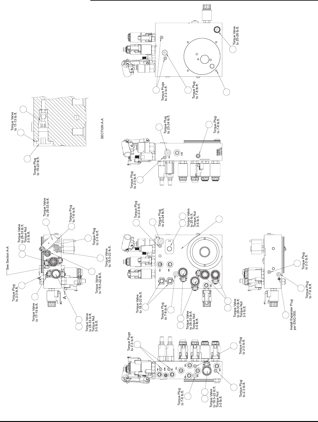
76
PUMP ASSEMBLY (A-00254)
1
2
3
5
6
7
89
10
11
12
13
14
15
21
21
24
19
17 17 17
24 17
19
22
17
19
23
17 17
20 4
19
17 20
19
17
16
20
25
18

77
PUMP ASSEMBLY PARTS LIST
Item No. Part No. Description Qty.
1 B02-15-0496 Manifold, Valve Housing 1
2 B02-14-0108 Valve, Counterbalance 2
3 B02-15-0472 Manual Pump, Extend/Retract/Rotate 1
4 B02-14-0089 Valve, Cartridge (Outrigger Check) 1
5 B02-14-0109 Valve, Cartridge (Outrigger) 2
6 B02-14-0091 Valve, Check 1
7 B02-14-0110 Valve, Check 1
8 B02-14-0094 Valve, Proportional 1
9 B02-14-0095 Coil Sterling, Proportional Valve 1
10 B02-14-0111 Valve, Relief 1
11 B02-14-0097 Valve, Relief 1
12 B02-14-0098 Valve, Shuttle 1
13 B02-14-0099 Valve, Cartridge (Rotator) 1
14 B02-14-0100 Valve, Counterbalance 1
15 B02-14-0101 Valve, Cartridge (Basket Compensate) 1
16 B02-14-0114 Valve, Flow Control (Rotator) 1
17 B02-02-0245 Fitting, Plug, #2 ORB 11
18 B02-02-0246 Fitting, Hex Plug 1
19 B02-02-0248 Fitting, Plug, #4 ORB 5
20 B02-14-0112 Coil, 20 VDC, #8 5
21 B02-14-0113 Coil, 20 VDC, #10 5
22 B02-15-0497 Stud, #1/4-20 x 5/8 4
23 B02-15-0498 Expansion Plug 1
24 B02-02-0235 Fitting, Plug, #6 ORB 2
25 B02-15-0478 Seal Ring 1

78
PUMP ASSEMBLY, CONTINUED
1
2
3
4
5
6
7
8
9
10
11
12
13
14
15
16
17
18
15
19
20
21
22

79
PUMP ASSEMBLY PARTS LIST, CONTINUED
Item No. Part No. Description Qty.
1 B02-15-0513 Reservoir 1
2 B02-15-0470 Pump Assembly, 2.09 CCM 1
3 B02-15-0471 Motor, Pump, 24 VDC 1
4 B02-15-0500 Coupling, .875 x 2.795 1
5 B02-15-0501 Filter, Hydraulic 1
6 B02-15-0476 Sight Glass 1
7 B02-15-0477 Socket Head Cap Screw, M8 x 85 2
8 B02-02-0247 Fitting, Plug, M14 x 1.5 x 5.8 1
9 B02-15-0478 Seal Ring 1
10 B02-15-0485 Clamp, Band, #10-16 2
11 B02-15-0480 Filter, Suction 1
12 B02-15-0504 Allen Nut, 1/4-20 4
13 B02-02-0255 Fitting, M18 x HB-90M x HB-90 1
14 B02-15-0503 O-Ring, 110.72 x 3.53 NBR 70 D 1
15 B02-02-0279 Fitting, JIC-8 x Push On FS x PO 2
16 B02-15-0505 Hose, Black, 1/2 x 6” 1
17 B02-02-0280 Fitting, JIC-8 x #6 MxM 1
18 B02-15-0506 Cap Screw, #5/16-18 x 1 1/4 2
19 B02-02-0283 Fitting, JIC-8 x G 3/4 MxM 1
20 B02-02-0281 Fitting, Plug, #12 ORB 2
21 B02-02-0282 Fitting, 3/8 NPT x 1/2 MxHB 1
22 B02-15-0507 Hose, Black, 1/2 x 15” 1
B02-02-0276 Fitting, Plug, #8 ORB (Under Reservoir) 1
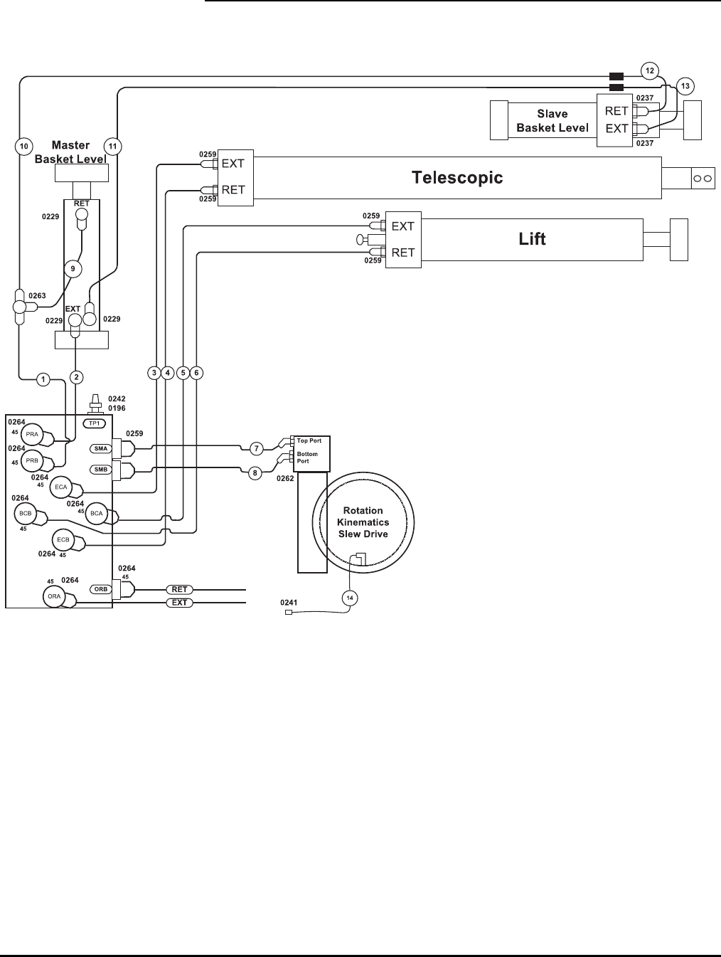
80
BOOM AND ROTATION HYDRAULIC LINES (A-00269)

81
BOOM AND ROTATION HYDRAULIC LINES PARTS LISTS
Item No. Part No. Description Fittings
1 B02-01-0274 #4 x 42” Hydraulic Hose 4-6 FFORX 4-4 FFORX
2 B02-01-0275 #4 x 42” Hydraulic Hose 4-6 FFORX 4-4 FFORX
3 B02-01-0276 #6 x 66” Hydraulic Hose 6-6 FFORX 6-6 FFORX
4 B02-01-0277 #6 x 66” Hydraulic Hose 6-6 FFORX 6-6 FFORX
5 B02-01-0278 #4 x 48” Hydraulic Hose 4-6 FFORX 4-6 FFORX 45
6 B02-01-0279 #4 x 48” Hydraulic Hose 4-6 FFORX 4-6 FFORX 45
7 B02-01-0280 #4 x 36” Hydraulic Hose 4-6 FFORX 4-6 FFORX
8 B02-01-0281 #4 x 36” Hydraulic Hose 4-6 FFORX 4-6 FFORX
9 B02-01-0231 #4 x 10” Hydraulic Hose 4-4 FFORX 90S 4-4 FFORX
10 B02-01-0232 #4 x 420” Hydraulic Hose 4-4 FFORX 4-4 FFORX
11 B02-01-0233 #4 x 420” Hydraulic Hose 4-4 FFORX 4-4 FFORX
12 B02-01-0234 #4 x 16” Hydraulic Hose 4-4 MFFOR 4-4 FFORX
13 B02-01-0235 #4 x 16” Hydraulic Hose 4-4 MFFOR 4-4 FFORX
14 B02-01-0204 #3 x 32” Hydraulic Hose 2 MNPT 2 MNPT 90SW
FITTINGS
Part No. Description Qty.
B02-02-0259 #6 MORFS - #6 MORB, STR 6
B02-02-0264 #6 MORFS - # 6 MORB, 45º 8
B02-02-0263 #4 MORFS, Tee 1
B02-02-0237 #4 MORFS - #6 MORB, STR 2
B02-02-0262 #6 MORFS - #10 MORB, 45º 2
B02-02-0196 #4 MORB - #2 MNPT, STR 1
B02-02-0241 #2 NPTFM Coupling 1
B02-02-0242 #2 QD Plug 1
B02-02-0229 #4 MORFS - #6 MORB 90 3
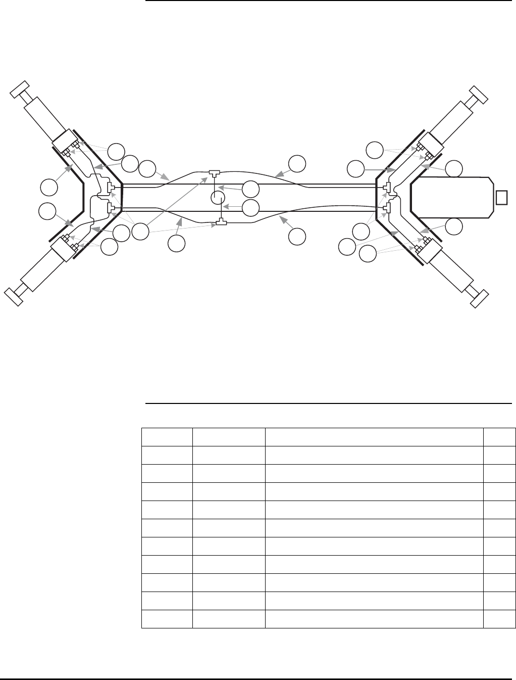
82
OUTRIGGER HYDRAULIC LINES (A-03182)
EXT
RET
RET
EXT
RET
EXT
EXT
RET
EXT
RET
2
1
4
6
1
99
10
10 10
10
1
3
5
2
2
12
7
8
OUTRIGGER HYDRAULIC LINES PARTS LIST
Item No. Part No. Description Qty.
1 B02-01-0213 #4 x 28” Hydraulic Hose 4
2 B02-01-0214 #4 x 28” Hydraulic Hose 4
3 B02-01-0215 #6 x 56” Hydraulic Hose 1
4 B02-01-0216 #6 x 56” Hydraulic Hose 1
5 B02-01-0219 #6 x 28” Hydraulic Hose 1
6 B02-01-0220 #6 x 28” Hydraulic Hose 1
7 B02-01-0327 #6 x 46” Hydraulic Hose 1
8 B02-01-0328 #6 x 46” Hydraulic Hose 1
9 B02-02-0258 Fitting, Tee, #6 MORFS 6
10 B02-02-0259 Fitting, #6 MORFS - #6 MORB 8
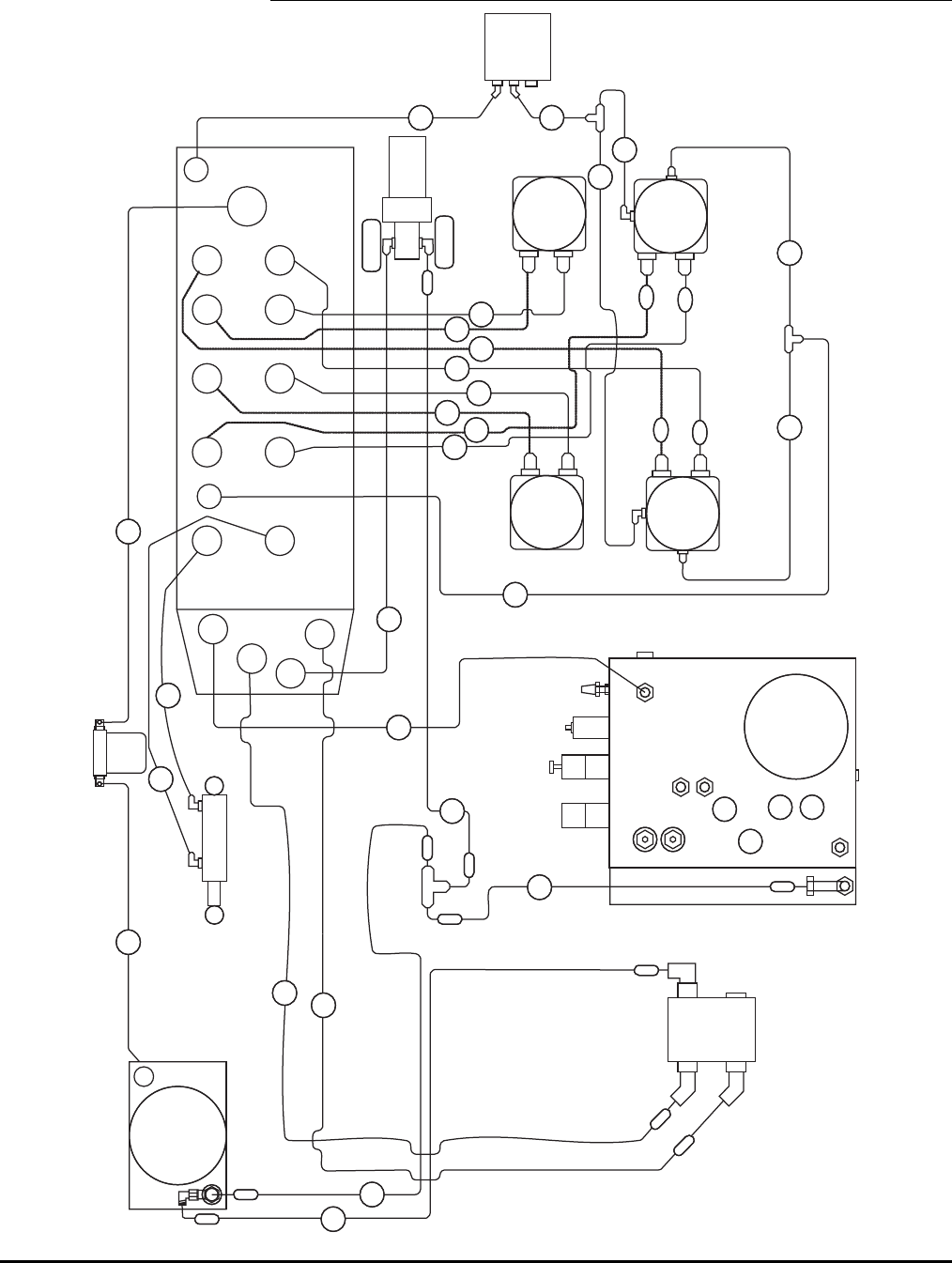
83
TRAILER HYDRAULIC LINES – 4WD (A-01075)
P1A
P2B
P1B
P2A
S1A
S1B
TB M2A
M2B
M3A
M3B
M1A
M1B
M4A
M4B
TA
B1
Aux
Pump
P
T
8-18 Metric
90
6-14 Metric
90
TP2
TP3
ORB
SMA
SMB
Banjo
Bolt
Pump
Side
Rear
Control
Side
Front
Control
Side
Rear
Pump
Side
Front
OIL
COOLER
Dual
Pump
5GPM
Driver
Top Top
Bottom
Front
Rear
Front
Rear
Bottom
6
7
1
4
8
9
5
13
12
10
14
11
MANUAL
BRAKE
RELEASE
2
3
11
15
16
17
18
19
20
21
22
23
24
24
#12ORBM-#10ORBFM STR
6410-12-10
#10MORFS-#10MOBR-#10MORFS Tee
FF6804-10-10-10
#8MORFS-#12MORB STR
FF6400-8-12
(2) #8MORFS-#10MORB 45
FF6802-8-10
10MORB Plug
6408-H-10
#10MORFS-#12ORB 90
FF6801-10-12
#4MORFS-#4MORB 90
FF6801-4-4
#4MORFS-#4MORB 90
FF6801-4-4
(2)#10MORB-#6FMORB
6410-L-10-6
(2)#6MORFS-#6MORB 90
FF6801-6-6
(2)#10MORB-#6FMORB
6410-L-10-6
(2)#6MORFS-#6MORB 90
FF6801-6-6
(2) #6MORFS-#10MORB STR
FF6400-6-10
(2) #4MORFS-#4MORB 90
FF6801-4-4
#4MORFS Tee
FF2603-4-4-4
#4MORFS Tee
FF2603-4-4-4
#8MORFS Tee
FF2603-8-8-8
#6MORFS-#6MORB STR
FF6400-6-6
(2) #6MORFS-#10MORB STR
FF6400-6-10
(2) #4MORFS-#4MORB 90
FF6801-4-4
FF6801-6-6
FF6400-4-6
FF6400-6-6
FF6400-4-6
FF6400-6-6
FF6400-6-6 FF6400-6-6
FF6400-6-6 FF6400-6-6
FF6400-6-6
FF6400-6-6
FF6400-6-6
FF6400-8-8
FF6400-4-4
FF6400-4-4
(2) #4MORFS-#4MORB 45
FF6802-4-4
#10MORFS-#10FMORFS 90
FF6500-10-10
B1
Brake
FF6801-L-6-6
FF6801-6-6
90
90L
90
STR
14
15
18
19
1A
2A
2B
3B
4B
3A
1B
7A
6A
4A
5
Oil Filter

84
TRAILER HYDRAULIC LINES PARTS LISTS
Item No. Part No. Description
1 B02-01-0402 #10 x 28” Hydraulic Hose
2 B02-01-0401 #8 x 154” Hydraulic Hose
3 B02-01-0398 #8 x 16” Hydraulic Hose
4 B02-01-0400 #8 x 24” Hydraulic Hose
5 B02-01-0399 #8 x 18” Hydraulic Hose
6 B02-01-0386 #6 x 30” Hydraulic Hose
7 B02-01-0387 #6 x 30” Hydraulic Hose
8 B02-01-0397 #6 x 166” Hydraulic Hose
9 B02-01-0396 #6 x 150” Hydraulic Hose
10 B02-01-0385 #4 x 118” Hydraulic Hose
11 B02-01-0379 #4 x 16” Hydraulic Hose
12 B02-01-0382 #4 x 30” Hydraulic Hose
13 B02-01-0383 #4 x 40” Hydraulic Hose
14 B02-01-0393 #6 x 138” Hydraulic Hose
15 B02-01-0392 #6 x 138” Hydraulic Hose
16 B02-01-0388 #6 x 38” Hydraulic Hose
17 B02-01-0389 #6 x 38” Hydraulic Hose
18 B02-01-0395 #6 x 138” Hydraulic Hose
19 B02-01-0394 #6 x 138” Hydraulic Hose
20 B02-01-0390 #6 x 62” Hydraulic Hose
21 B02-01-0391 #6 x 62” Hydraulic Hose
22 B02-01-0380 #4 x 21” Hydraulic Hose
23 B02-01-0384 #4 x 10⁵” Hydraulic Hose
24 B02-01-0381 #4 x 25” Hydraulic Hose
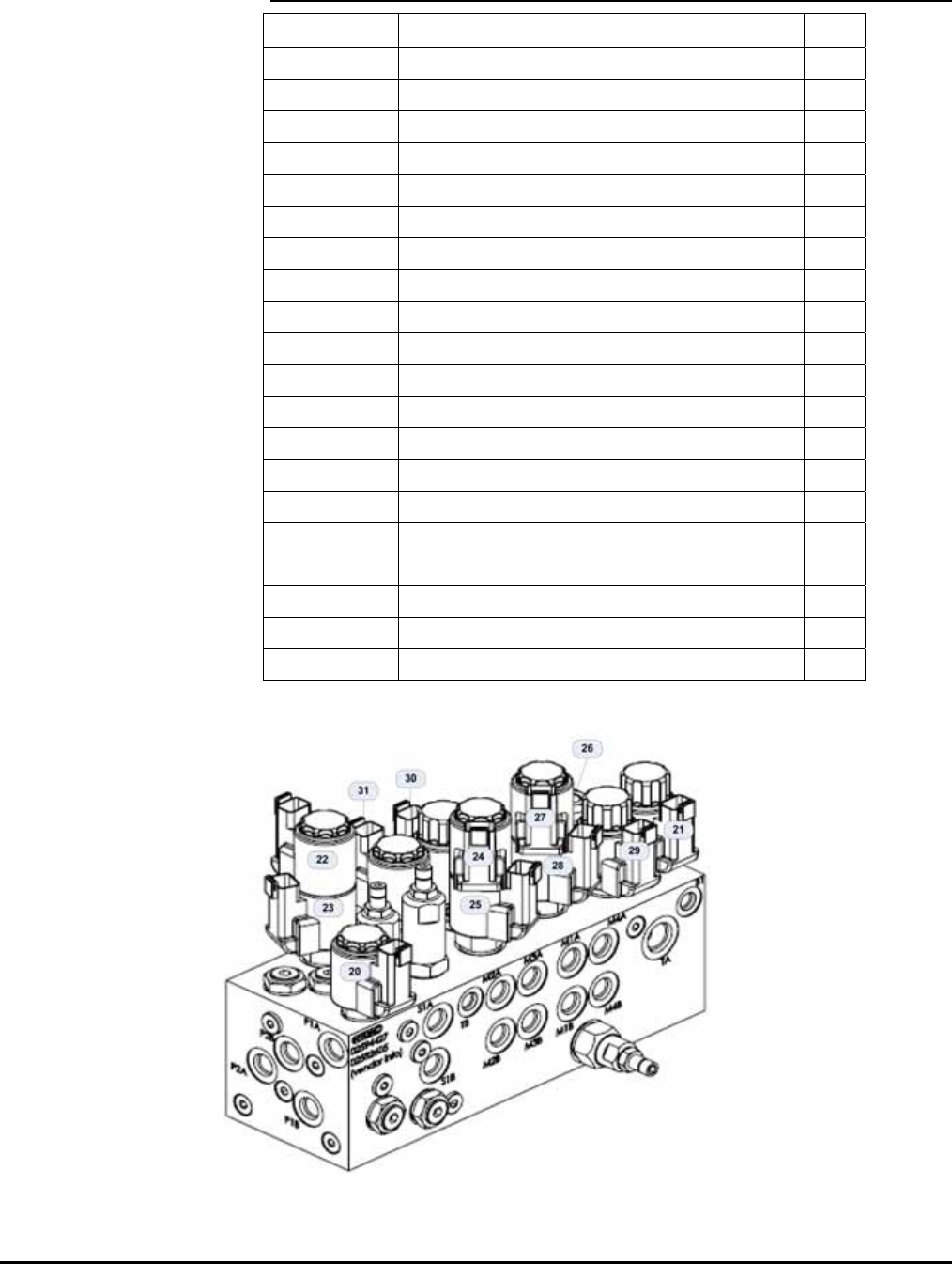
85
FITTINGS
Part No. Description Qty.
B02-02-0259 #6 MORFS - #6 MORB, STR 10
B02-02-0293 #8 MORFS - #8 MORB, STR 1
B02-02-0260 #6 MORFS - #6 MORB, 90º 6
B02-02-0287 #4 MORFS - #4 MORB, STR 2
B02-02-0288 #4 MORFS - #4 MORB, 90º 6
B02-02-0289 #4 MORFS, Tee 2
B02-02-0294 #6 MORFS - #6 MORB, 90ºL 1
B02-02-0295 #12 MORB - #10 FMORB 1
B02-02-0296 #10 MORFS - #10 MORB - #10 MORFS, Tee 1
B02-02-0297 #10 MORFS - #10 FMORFS, 90º 1
B02-02-0298 #8 MORFS - #12 MORB, STR 1
B02-02-0299 #8 MORFS - #10 MORB, 45º 2
B02-02-0300 #10 MORFS - #12 MORB, 90º 1
B02-02-0303 #10 MORB Plug 1
B02-02-0304 #10 MORB - #6 FMORB 4
B02-02-0305 #6 MORFS - #10 MORB, STR 4
B02-02-0237 #4 MORFS - #6 MORB, STR 2
B02-02-0307 #8 MORFS, Tee 1
B02-02-0308 #4 MORB Plug 1
B02-02-0309 #8MORFS - #12 MORB, 90º 2
4WD MANIFOLD (A-01033)
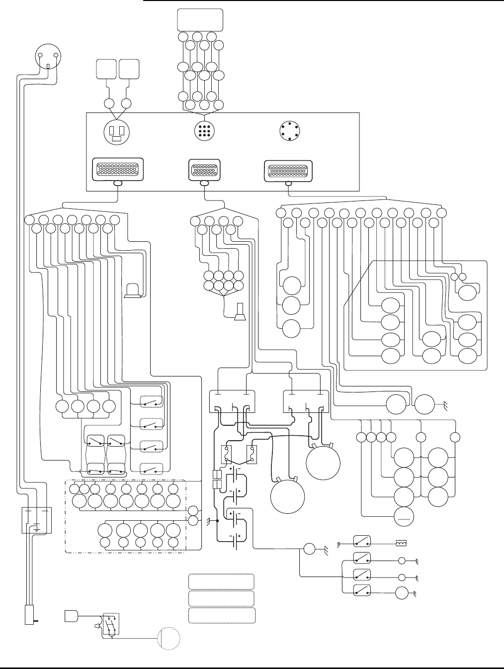
86
WIRE HARNESSES
111
12 3
5
Prim
Cyl
C5
Sec
Cyl
C16
Jib
Cyl
C17
1
12
2436
1
12
2435
18
23 16
LF
C1
LR
C3
RF
C2
RR
C4
LF
LR
RF
RR
24
1
3
2
4
27
26
13
15
14
16
22
23
Strobe
1
16
31
B- B+
M-
Main
Pump
Motor
A2E2
D1E1
EnableSpeed
R B O Br
+ -
X Y
8
15
22
23
Motor
Controller
Main
Level
Sensor
Front
Boom
Switches
Boom
Down
Relay NC
C22C23C24C25 C20C21C26
3334 11 10 9876
12
31
B- B+
M-
EnableSpeed
20
Motor
Controller
Aux
Aux
Pump
Motor
A2E2
D1E1
Drive
Manifold
200
Amp
Fuses
C27C28C29C30C31
1718192021
1 2
Motor
Cntl
B+
Motor
Cntl
B-
3
4
6
7
8
9
Wh
Blu
Bla
Or
Re
Gr
B
E
F
A
D
C
Upper
Control
Box
IEC Recp.
35
PLT
DN
C14
PLT
UP
C13
Rot
CCW
C9
Rot
CW
C10
Boom
RET
C12
Boom
EXT
C11
Prop
Coil
C8
Chk
Valve
C6A
OR
EXT
C6
OR
RET
C7
+ -
Pump
10
Throttle
Sol
Choke
Sol
Engine
Start
Fuel
Switch
Engine
Stop
Fan
Engine
Run
242725 269
M
Fan
Fuel Sol
Start Sol
Engine Spark
LN
Platform Plug
Engine Stop
Start
Fuel
Fan
NO
Jib
Switches
##NO
#NC
#NC
#
Switch is forced open
when Boom is lifted
##
Switch is forced Closed
when Boom is Stowed
##NO
**
NO
**
NO
**
NO
**
Switch is forced Closed
when outrigger is loaded
**
GFCI
Plug
P4 & P5
Connector
P3
Turntable Connector P1
Analog Connector
J4
Platform Connector
P2
Lift/Engine Connector
20
31
21
7
8
13
14
23
9
10
34
17
18
35
32
32
Oil
Press
Switch
AC
Switch
Generator
AC Switch
AC
Plug
Engine
Start
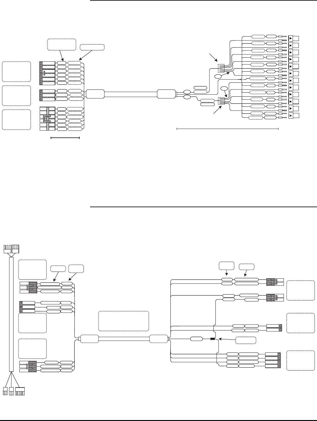
87
MANIFOLD WIRE HARNESS (A-00785)
A
B
C
D
E
F
A
B
C
A
B
C
D
E
F
C20
C21
C22
C23
C24
C25
GND
C27
C28
C29
C30
C31
GND
C26(+)
C26(-)
C22
C25
Deutsch Term.
0462-201-16141
C20
C24
C21
C23
Wires
Connected
& Sealed
Stripe wire
to 12"
1
2
1
2
1
2
1
2
1
2
1
2
C27 1
2
C28 1
2
C29 1
2
C30 1
2
C31 1
2
C26 + 1
2
C26 -
GND 2
GND 1
3"
3"
9"
9"
Deutsch
DT06-2S
2PinPlug
W2S Wedge
12020926
6 Pin FM Conn
12089188
FM Term
12015323
Green Wire Seal
12010717
3 Pin Male Conn
12089040
Male Term
12015323
Green Wire Seal
12020786
6 Pin Male Conn
1208089040
Male Term
12015323
Green Wire Seal
156" (13')(+/- 2") 16 Cond 18ga Wire
SOOW or Equivalent
Stripe wire
to 4"
Label Wires
Both Ends
Wires
Connected
& Sealed
Orange
White
Green
Red
Blue
White/B
Black
Red/B
Green/B
Orange/B
Blue/B
Green/W
Red/W
Blue/W
Black/W
Wire Color
Orange
White
Green
Red
Blue
White/B
Black
Red/B
Green/B
Orange/B
Blue/B
Green/W
Red/W
Blue/W
Black/W
A-00785
Rev-
Label
A-00785
Rev-
Label
GAS ENGINE WIRE HARNESS (A-01034)
Engine Stop
Engine Start
Throttle
Choke
Engine RunRed
Red
Green
Black
Blue
White
Orange
White
Blue
Orange
Green
Black
Strip Wires 6"
120" (10')
18ga-10 Cond Wire
SOOW or Equivalent
Strip Wires 3"
A
B
C
D
GND
12010973
2 Pin Male Conn
12089040
Male Term
12015323
Green Wire Seal
12020830
4 Pin Male Conn
12089040
Male Term
12015323
Green Wire Seal
A
B
1"
5"
Delphi
Weather Pack
Delphi
Weather Pack
12020829
3 Pin Female Conn
12089188
Female Term
12015323
Green Wire Seal
C
B
A
Throttle
Engine Start
Engine Stop
C
B
A
Engine Run
GND
Choke
12020827
3 Pin Male Conn
12089040
Male Term
12015323
Green Wire Seal
C
B
AGen Switch
Oil Press Sw (+)
Oil Press Sw
B
A
A
B
GND
Oil Press Sw (+)
Oil Press Sw
Gen Switch
12015792
2 Pin Female Conn
12089188
Female Term
12015323
Green Wire Seal
Delphi
Weather Pack
12020829
3 Pin Female Conn
12089188
Female Term
12015323
Green Wire Seal
A-01034
Rev-
A-01034
Rev-
Label Both
Ends
R/BL
Or/BL
Wh/Bl
R/BL
Or/BL
Wh/Bl
Label Wire
Color
Label
Wire
Color
Green
Green
5"
Splice &
Heat Sealed
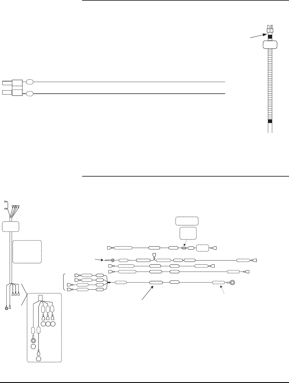
88
CHOKE /THROTTLE SOLENOID WIRE HARNESS (A-01042)
Weather Pack
FM Term
12089188
Cable Seal
12015323
FM Housing
12015792
B
A
B
W
20" 18ga TXL
Or Equivalent
A-01042
Rev- Label
Put Wires
in 16"
Split
tubing
Heat Seal
Both
ends
1"
ENGINE RELAYS WIRE HARNESS (A-01044)
Starter S 87 Starter20"
15"Ign K 87a Ign Coil
Fuel Sw
¼” Female Spade
15"
5/16" Ring Term
¼” Female Spade
18"
All wires 18 ga
TXL or Equivalent
All Measurements
are +/- 0.250 In
+12V
Labels
A-01044
Rev-
10" Split
Tube Wrap
Tape At
Each End
Engine
Run
Engine Run 10"
Resistor
2.2k-Ohm
.5Watt
Solder inline &
Heat Shrink
4"
¼” Female Spade
¼” Male Spade
Red
Black
Yellow
Orange
Wire
Color
¼” Male Spade
Wire
Length
¼” Female
Spade
4" RedFAN Green
Fuel F 87
¼” Female Spade
¼” Female Spade
¼” Female Spade
8"
8"
6"
6"F30
3"
3"
3"
8"
6"
O
Y
B G R
Heat
Shrink
Label
Delphi Weather Pack
Male Term 12089040
Green Seal 12015323
S30
C30
T30
Wire Color
12v +
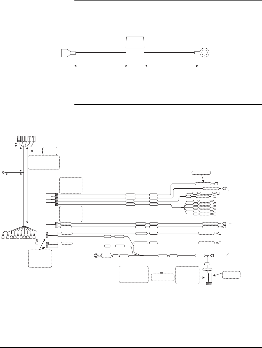
89
ATC FUSE HOLDER (A-01049)
¼” Female Spade Ins
5/16" Ring
Term
4"- 6" Leads
12 ga Wire
4"- 6" Leads
12 ga Wire
ATC Fuse Holder
Waytek # 46278
or Equivalent
START/STOP/RUN WIRE HARNESS (A-01098)
A
B
C
D
12020832
4 Pin Female Conn
12089188
Female Term
12015323
Green Wire Seal
¼” Male Spade
Insulated
¼” Female Spade Insulated
Start S 86
Engine Run
Wire Label
All wires
TXL or Equivalent
All Measurements
are +/- 0.250 In
24"
26"
20"
20"
Split Tube Wrap
& Heat Shrink
Each End
Fuel F 86
6"
4"
6"
Splice & Heat
Shrink Seal
¼” Ring
Terminal
7"
10"
2"
11"
5"
White
Red
Blue
Green
Black
Length
Wire
Color
K30
Fan
A
B
A
B
Yellow
Orange/Bl
Choke C 87
Throttle T 87
28"
28"
Black
Black15"
15"
9"
12010973
2 Pin Male Housing
12089040
Male Terminal
12015323
Green Wire Seal
Throttle
Choke
18"
A-01098
Rev - Label
Tape Both Sides
of Drop Out
A
B
Choke C 86
Throttle T 8628"
28"
Orange
Black
12015792
2 Pin Female Conn
12089188
Female Term
12015323
Green Wire Seal
Black
GND 85
A
B
A–Leave
Open
12010973
2 Pin Male Housing
12089040
Male Terminal
12015323
Green Wire Seal
Delphi Weather Pack
Delphi Weather Pack
Delphi Weather Pack
Delphi Weather Pack
Frame
Gnd
4" GND 85
GND 85
GND 85
6"
8"
8"
GND 85
Stop K 86
Choke
Throttle
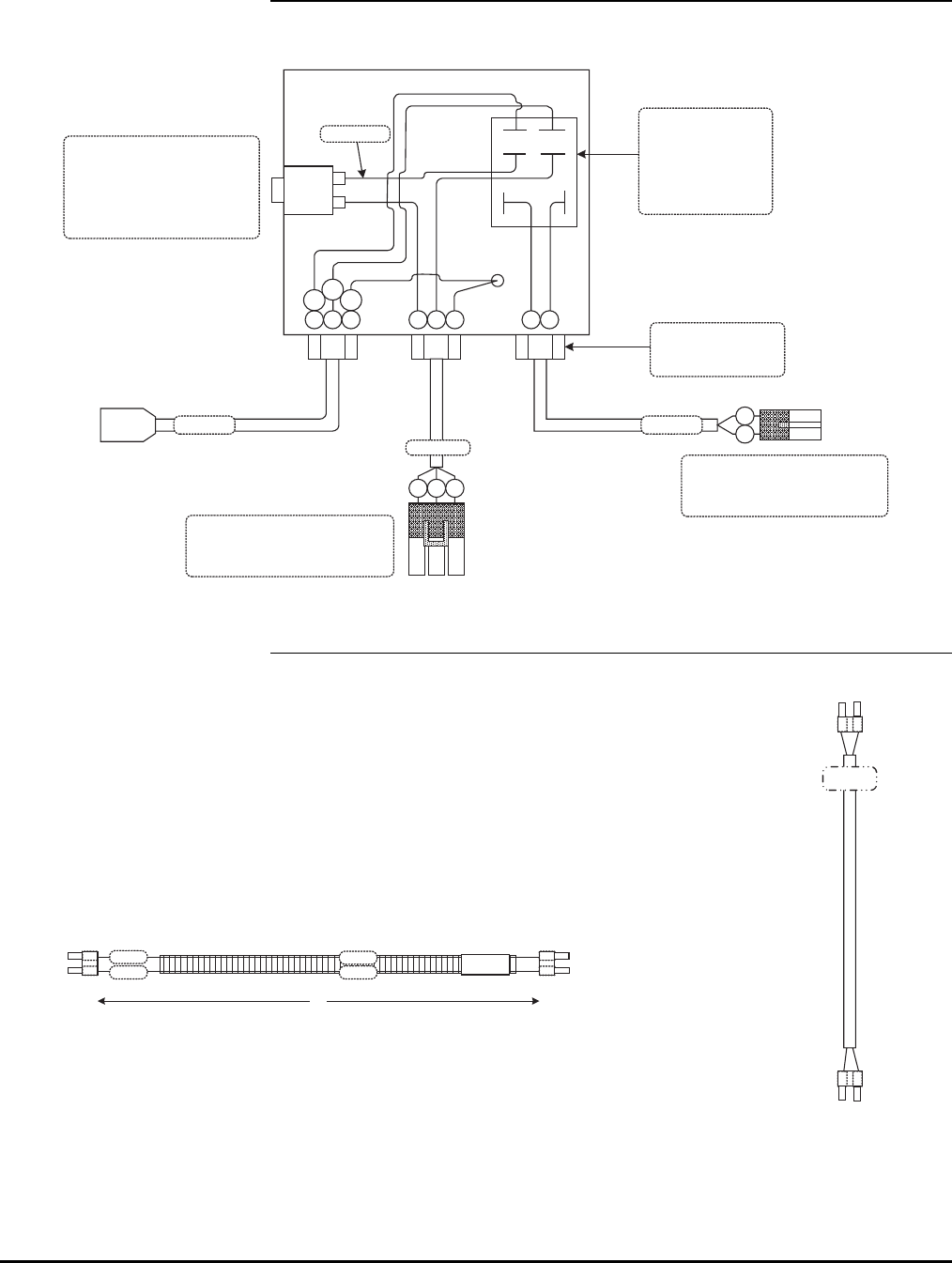
90
GENERATOR SWITCHER BOX ASSEMBLY (A-03040)
20
Amp
B W GB W G B W
B W G
A
B
C
A
B
B
W
B01-01-0179
B01-01-0178
Ground
Stud
Br
Bl Y/
g
B01-06-0056
30 Amp Relay
DPST – NO
Allied Electronics
#850-0345
Or Equivilant
B01-10-0354
20 Amp Circuit Breaker
W/.250 Male Spade Terminal
Allied Electronics
#886-0036
Or Equivilant
Cord Grip
Heyco #3231
Or Equivilant
Delphi Weather Pack
2 Pin Male Housing 12010973
Male Terminal 12089040
Green Seal 12015323
Delphi Weather Pack
3 Pin Male Housing 12015793
Male Terminal 12010293
Gray Seal 12010293
Box-A-01015
B01-01-0181
B01-01-0180
WIRE ASSEMBLY – FAN (A-03041)
Weather Pack
FM Term
12089188
Cable Seal
12015323
FM Housing
12015792
B
A
Black
Red
All wires 18 ga
TXL or Equivalent
All Measurements
are +/- 0.250 In
36"
GND
Relay
Label
Wires Wire
Color
B
A
40" Loom
Tape each End &
Middle
A-3041
Rev.
Label
B
A
Weather Pack
FM Term
12089188
Cable Seal
12015323
FM Housing
12015792
B
A
A-03041
Rev.

91
IEC CORD MALE – US MARKETS (A-03042)
North America
120V Male Plug
Current 15 AMP
Voltage 120/240VAC
SO cable or
Equivalent
18"
A-03042
Rev
Label
IEC90DegreePlug
Interpower
IEC 60320 C19
Mold 012
Minimum Requirements
GENERATOR 110V WIRE HARNESS (A-03043)
W B
W B
3"
3"
3"
3"
2"
2" B
B
B
WW
W
1/2” Grommet OD
Delphi Weather Pack
12010717
3 Pin Male Housing
12124582
Male Terminal 12/14ga
12010293
Seal 12/14ga
B
C
A
B
W
G
.0625"
12-3 SO
Or Equivilant
36" (+/- 2")
OIL SWITCH ASSEMBLY (A-03044A)
A
B
Delphi Weather Pack
12010973 (B01-09-0109)
2 Pin Male Housing
12089040 (B01-09-0110)
Male Terminal
12015323 (B01-09-0093)
Green Seal
R
B
Wires should be 17-18" Long
B00-00-0170
Wire Casing
16"
A-03044
OIL PRESSURE SWITCH 4WD
TRANSDUCER DIRECT #TDPS211A8FW
PVC
Tape
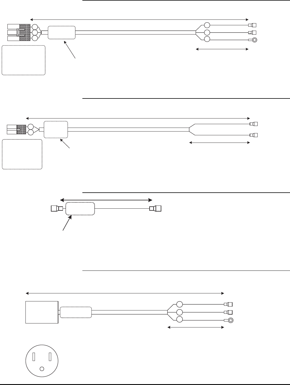
92
CORD ASSEMBLY 110V GENERATOR (B01-01-0178)
B W G
A
B
C
B01-01-0178
Rev
BWG
¼” Female Spade
¼” Female Spade
#10 Ring Terminal
24"
14-3
SO or Equivalent
4"
Delphi Weather Pack
12015793
3 Pin Female Housing
12124580
Female Terminal 12/14ga
12010293
Seal 12/14ga
Label
CORD ASSEMBLY GENERATOR SWITCH (B01-01-0179)
A
B
B
WB01-01-0179
Rev
¼” Female Spade
¼” Female Spade
4"
28"
18-2
SO or Equivalent
Label
Delphi Weather Pack
12010973
2 Pin Male Housing
12089040
Male Terminal
12015323
Green Seal
CORD ASSEMBLY SWITCH JUMPER (B01-01-0180)
¼” Female Spade¼” Female Spade
14ga Black
TXL or Equivalent
All Measurements
are +/- 0.250 In
B01-01-0180
Rev
Label
CORD ASSEMBLY 110V AC PLUG – FM (B01-01-0181)
North America
110V Female Plug
BWG
¼” Female Spade
¼” Female Spade
4"
12"
14-3
SO or Equivalent
B01-01-0181
Rev
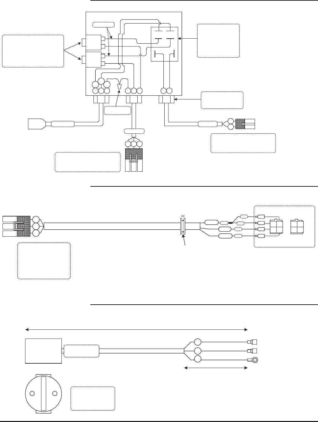
93
SWITCHER BOX ASSEMBLY – CE MODELS (A-03040CE)
20
Amp
G W BB W G B W
B W G
A
B
C
A
B
B
W
B01-01-0179
B01-01-0178
Br
Bl Y/
g
B01-06-0056
30 Amp Relay
DPST – NO
Allied Electronics
#850-0345
Or Equivilant
B01-10-0354
20 Amp Circuit Breaker
W/.250 Male Spade Terminal
Allied Electronics
#886-0036
Or Equivilant
Cord Grip
Heyco #3231
Or Equivilant
Delphi Weather Pack
2 Pin Male Housing 12010973
Male Terminal 12089040
Green Seal 12015323
Delphi Weather Pack
3 Pin Male Housing 12015793
Male Terminal 12010293
Gray Seal 12010293
Box-A-01015
B01-01-0181CE
B01-01-0180
20
Amp
B01-09-0005
Blue Wire Nut
220V GENERATOR WIRE HARNESS – CE (A-03043CE)
G G
W B
4"
2"
2"
1/2” Grommet OD
.0625"
14-3 SO
Or Equivilant
24" (+/- 2")
White
4"Black
B W G
A
B
C
Delphi Weather Pack
12015793
3 Pin Female Housing
12124580
Female Terminal 12/14ga
12010293
Seal 12/14ga
Green 2" Y W
G R
Generator
Wire Colors
CORD ASSEMBLY 220V AC PLUG – CE (B01-01-0181)
BWG
¼” Female Spade
¼” Female Spade
4"
12"
14-3
SO or Equivalent
B01-01-0181CE
Rev
InterPower
# 88010390
16A Socket or
Equiliviant
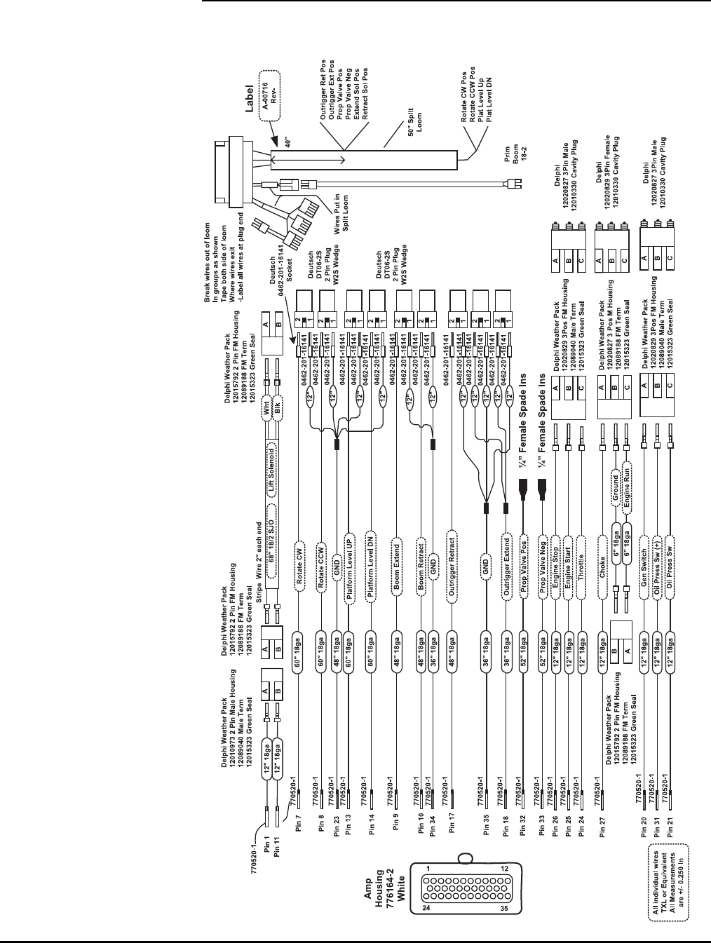
94
PUMP AND CYLINDER WIRE HARNESS (A-00716)
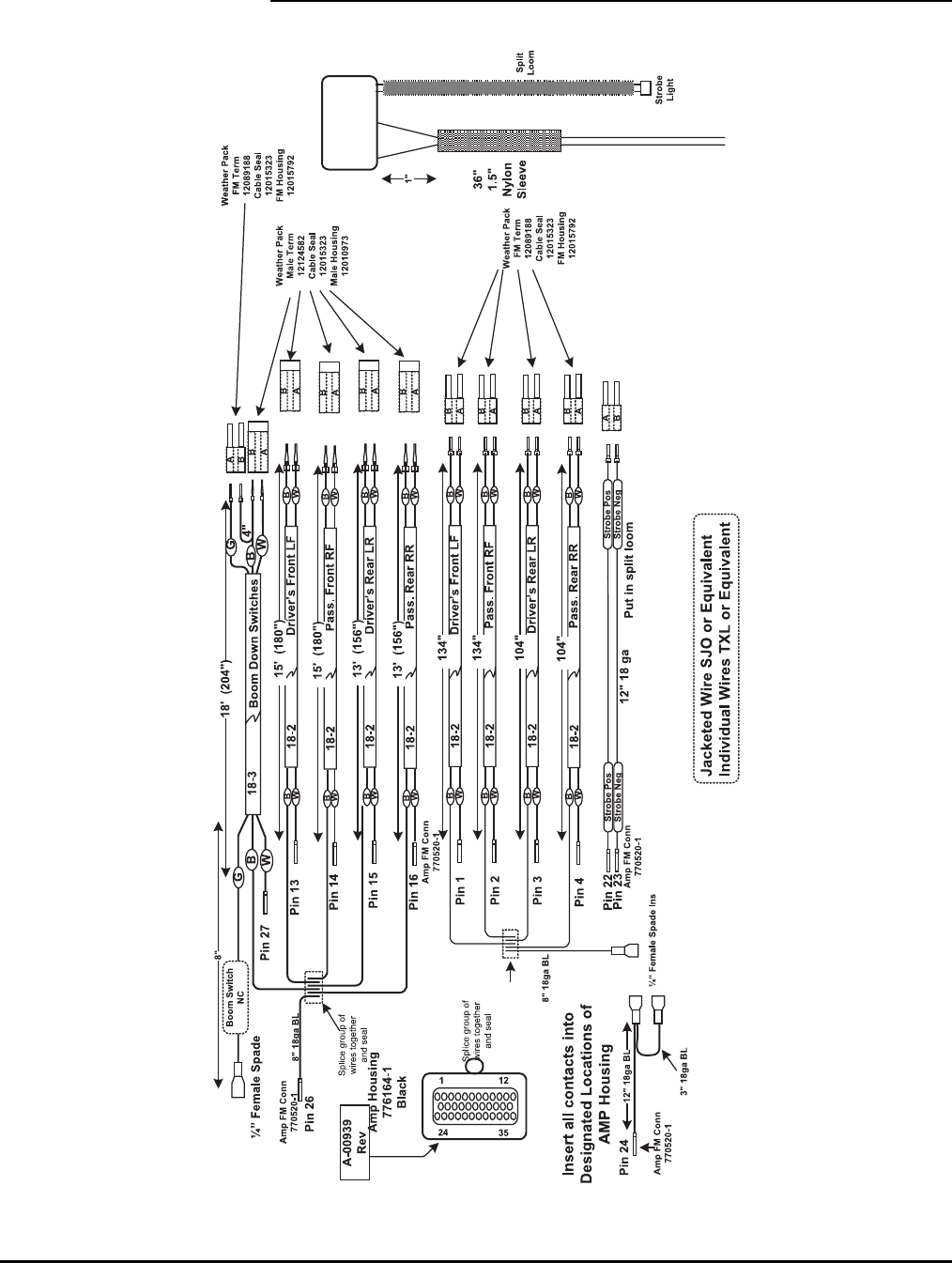
95
OUTRIGGER SWITCH & COIL WIRE HARNESS (A-00746)
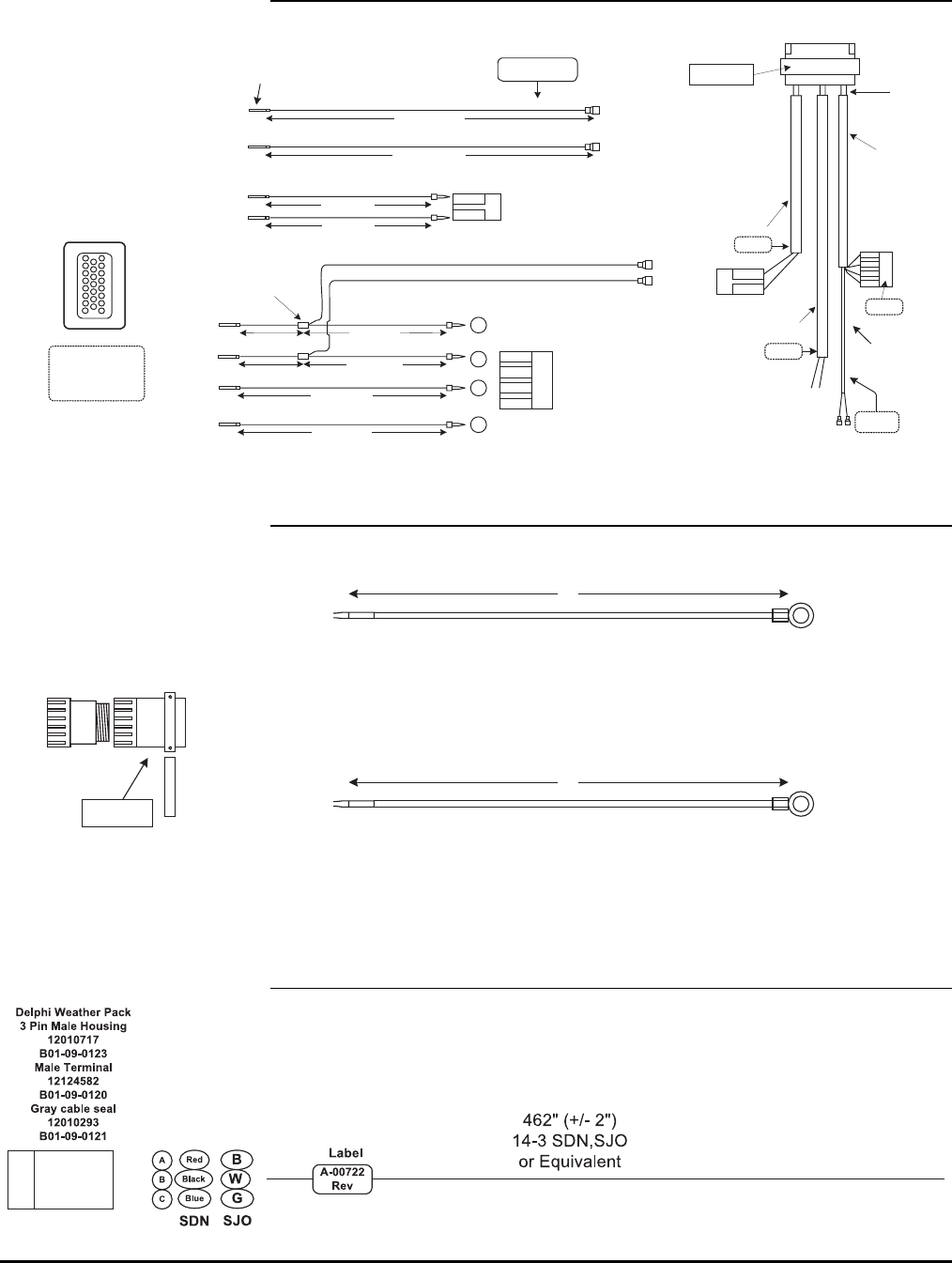
96
ANALOG HARNESS (A-00715)
Amp
Housing
770680-1
Black
Pin
1
¼” FM Spade
Insulated
Pump Speed Signal
3' (36") 18 ga Green
Pin
16
Motor Cntrl Enab
3' (36") 18 ga Yellow
¼” FM Spade
Insulated
Pin
810" 18 ga Red
Level Sensor +24
Pin
15 10" 18 ga Black
Level Sensor GND
Pin
22 18" 18 ga Orange
Level Sensor X
Pin
23 18" 18 ga Brown
Level Sensor Y
A
B
C
D
A
B
C
D
Weather Pack
12020830 4 Pos housing
Mates With 12020832
12089040 Male Terminal
12015323 Wire Seal
Amp
770680
A
B
C
D
Level
Sensor
Pump Speed Signal
Motor Cntrl Enab
32" Loom
AMP 770520-1
A-00715
Rev
Label
B
A
10" Loom
Pin
10 12" 18 ga Red
Pin
912" 18 ga Black
Engine Run +
Ground
B
A
Weather Pack
12010973 2 Pin Housing
12089040 Male Terminal
12015323 Wire Seal
18
2316
8"
8"
18" 18ga Red
18" 18ga Black
Splice & Heat
Shrink Seal
15" Loom
8" Loom
All wires
TXL or Equivalent
All Measurements
are +/- 0.250 In
Start
Contactor
Label
1"
¼” FM Spade
Insulated
¼” FM Spade
Insulated
Label
Motor
Control
Label
Engine
Run
Label
Individual
Wire Labels
POWER HARNESS (A-00718)
AMP
5/16" Ring Terminal
AMP
1-66740-1
Or
66740-6
5/16" Ring Terminal
AMP
1-66740-1
Or
66740-6
12ga Red
32"
32"
12ga
Black
Pin 2
Pin 1
Fill Strain Relief with RTV then put on
cable clamp and wipe off excess Bundle wires in 28" of loom.
Tape both ends if split loom is used
Batt Pos
Batt Neg
AMP 3 Pin Housing
206037-2
AMP Cable Clamp
206070-1
A-00718
Rev.
110 VAC TOWER-PLATFORM HARNESS (A-00722)
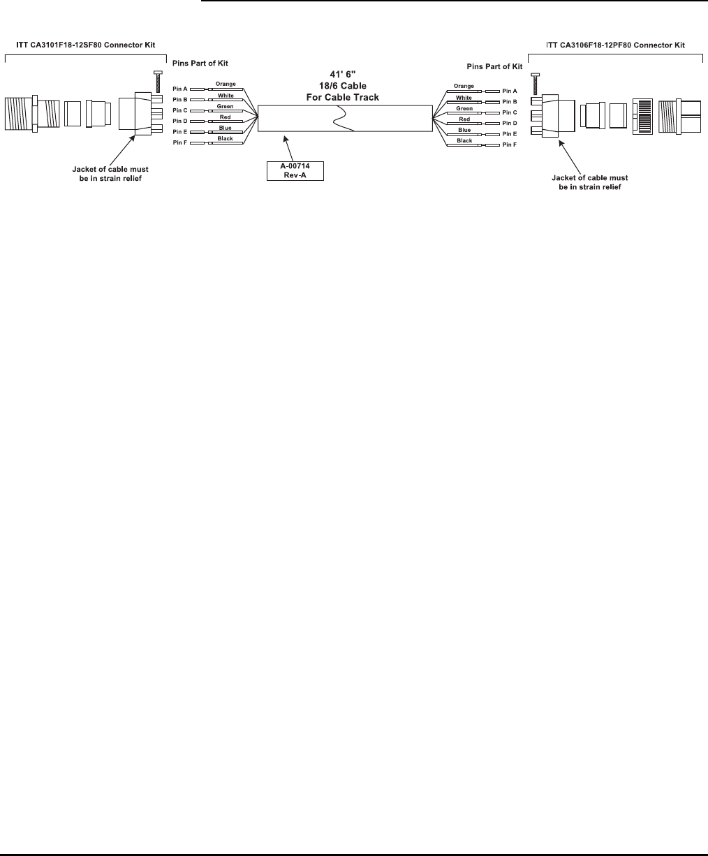
97
PLATFORM-GROUND COMMUNICATION CABLE (A-00714)
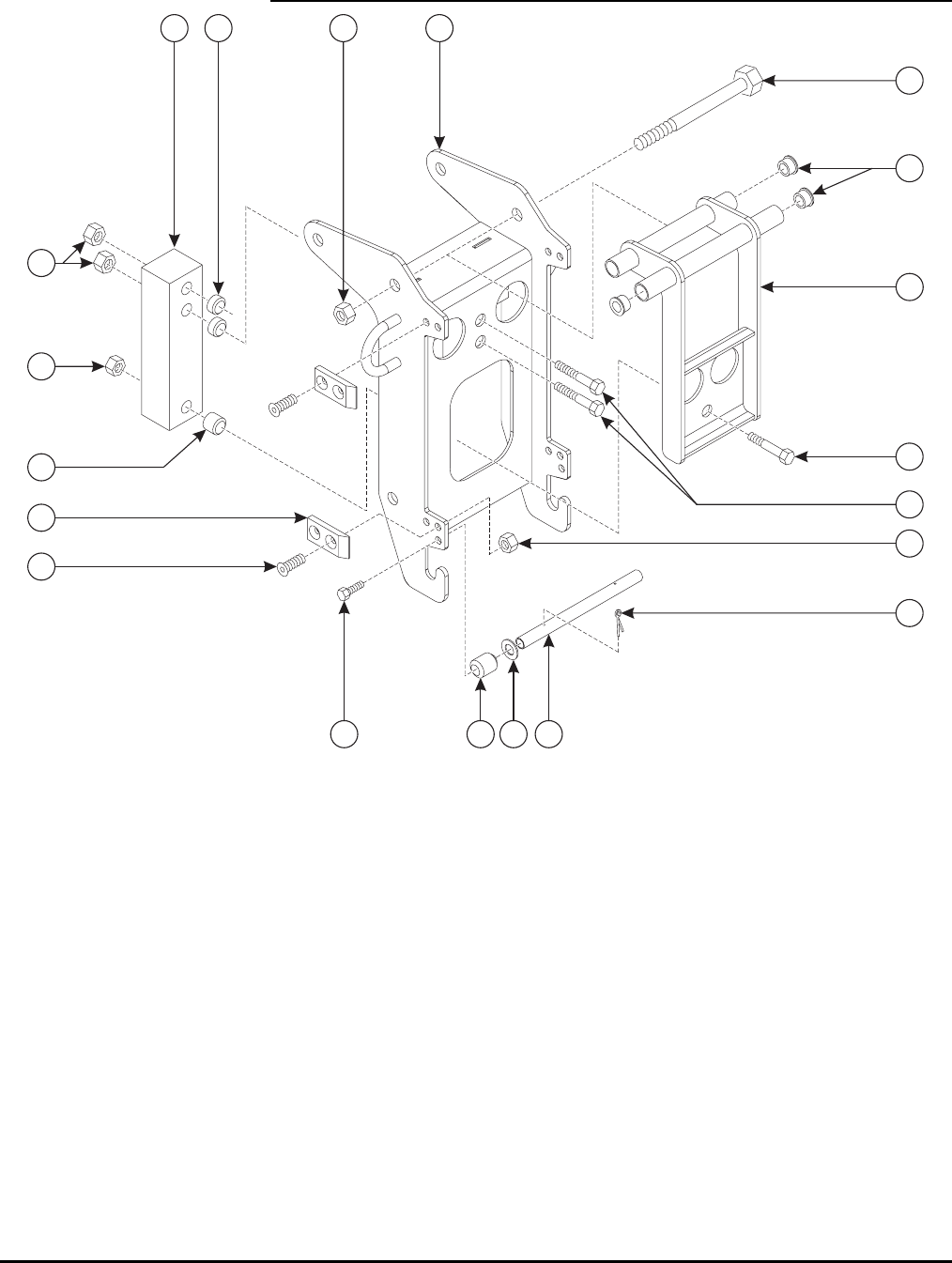
98
MATERIAL LIFT HOOK ASSEMBLY (OPTION A-00846)
1
2
3
4
5
6
7
8
9
10
11
12
13
15
16
17
18
4
14
19

99
MATERIAL LIFT HOOK PARTS LIST
Item No. Part No. Description Qty.
1 A-00977 Platform Mount Weldment – LS 1
2 A-00982 Load Sense Weldment 1
3 0096-0055 Cap Screw, M12 x 190 1
4 0096-0042 Hex Nut, Self-Locking, M12 3
5 A-00988-1 Load Cell 1
6 0096-0089 Cap Screw, M12 x 65 2
7 A-00990A Load Sense Spacer A 1
8 A-00990B Load Sense Spacer B 2
9 0096-0069 Cap Screw, M10 x 75 1
10 0096-0041 Hex Nut, Self-Locking, M10 1
11 A-00033 Bearing 4
12 A-00994 LS Roller Bar 1
13 A-00995 LS Roller 2
14 0096-0046 Washer, Flat, M12 2
15 0090-0147 Cotter Pin 2
16 0096-0009 Cap Screw, M8 x 10 2
17 A-00038 Ramp 4
18 0096-0003 Flat Head Cap Screw, M6 x 20 8
19 0096-0039 Hex Nut, Self-Locking, M6 8
20 A-00992 Load Sense Interface (Not Pictured) 1
21 0096-0085 Cap Screw, M6 x 60 3
22 0096-0039 Hex Nut, Self-Locking, M6 3
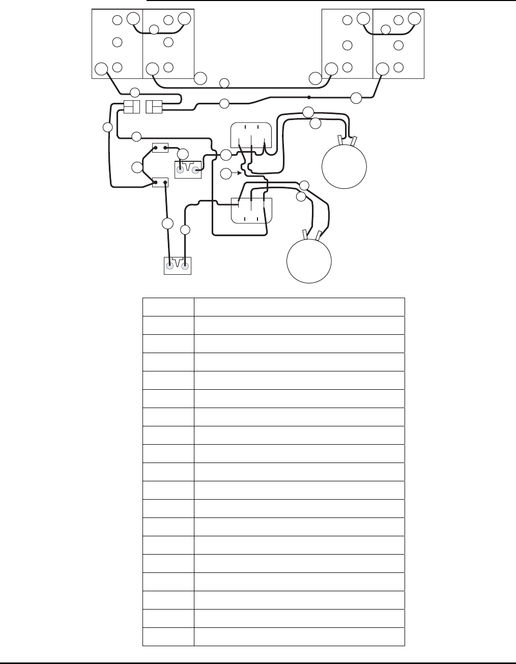
100
BATTERY LAYOUT
+
- +
- +
- +
-
-
+-
+
B+
B- M-
Drive
Motor
Pump
2
3 3
4
Motor
Controller
Enable0-5V
A2E2
D1E1
6
10
200 AMP
Fuse
1
531
Main
Pump
Motor
A2E2
D1E1
B+ M-
Enable 0-5V
31
B-
200 AMP
Fuse
D1
D3
D5
D4
8
9
Contactor
24VDC 100AMP
B01-06-0058
Contactor
24VDC 100AMP
B01-06-0058
7
D6 D2
11
Item No. Kit No. A-00272
1 30” Red, 2 Gauge, 5/16 Ring – Lug
2 45” Black, 2 Gauge, 5/16 Ring – 5/16 Ring
3 8” Black, 2 Gauge, 5/16 Ring – 5/16 Ring
4 22” Black, 2 Gauge, 5/16 Ring – Lug
5 24” Red, 2 Gauge, 5/16 Ring – Lug
6 48” Black, 2 Gauge, 5/16 Ring – Lug
7 22” Red, 2 Gauge, 5/16 Ring – Lug
8 48” Red, 2 Gauge, 5/16 Ring – 5/16 Ring
9 45” Black, 2 Gauge, 5/16 Ring – 5/16 Ring
10 19” Black, 2 Gauge, 5/16 Ring – 5/16 Ring
11 13” Red, 2 Gauge, 5/16 Ring – 5/16 Ring
Item No. Kit No. A-00934
D1 6” Red, 2 Gauge, 5/16 Ring – 5/16 Ring
D2 30” Red, 2 Gauge, 5/16 Ring – 5/16 Ring
D3 13” Black, 2 Gauge, 5/16 Ring – 5/16 Ring
D4 40” Red, 2 Gauge, 5/16 Ring – 5/16 Ring
D5 40” Black, 2 Gauge, 5/16 Ring – 5/16 Ring
D6 20” Red, 2 Gauge, 5/16 Ring – 5/16 Ring

101
ORDERING REPLACEMENT PARTS
To order replacement parts, contact the Bil-Jax Service Department by phone at
800-537-0540, by fax at 419-446-8202 or by email at techsupport@biljax.com.
For swift service, always have the part number available, as well as the
equipment model and serial number. When ordering parts by fax or email, always
provide the above information.
See Page 12 for Equipment Warranty information.
QUICK REFERENCE
Equipment Model: Bil-Jax 4527A Articulating Boom Lift
Serial Number: ______________________________________________
NOTES

102

NOTES

125 Taylor Parkway
Archbold, OH 43502
Phone (419) 445-8915
(800) 537-0540
Fax (419) 445-0367
http://www.biljax.com
Distributed by:
