Bilian Electronic R8188EU1 150Mbps Wireless N SDIO Module User Manual BL R8188EU1 EUS 2 6
Shenzhen Bilian Electronic Co., Ltd. 150Mbps Wireless N SDIO Module BL R8188EU1 EUS 2 6
User Manual

B‐LINKELECTRONICCO.,LTDinshenzhen
BL-8188EU1(EUS)
Product Specification
WLAN 11b/g/n USB MODULE Version: 2.6
FCC Statement
This device complies with part 15 of the FCC Rules. Operation is subject to the following two conditions: (1) This
device may not cause harmful interference, and (2) this device must accept any interference received, including
interference that may cause undesired operation.
Any Changes or modifications not expressly approved by the party responsible for compliance could void the user's
authority to operate the equipment.
Note: This equipment has been tested and found to comply with the limits for a Class B digital device, pursuant to
part 15 of the FCC Rules. These limits are designed to provide reasonable protection against harmful interference
in a residential installation. This equipment generates uses and can radiate radio frequency energy and, if not
installed and used in accordance with the instructions, may cause harmful interference to radio communications.
However, there is no guarantee that interference will not occur in a particular installation. If this equipment does
cause harmful interference to radio or television reception, which can be determined by turning the equipment off
and on, the user is encouraged to try to correct the interference by one or more of the following measures:
-Reorient or relocate the receiving antenna.
-Increase the separation between the equipment and receiver.
-Connect the equipment into an outlet on a circuit different from that to which the receiver is connected.
-Consult the dealer or an experienced radio/TV technician for help.
The 150Mbps Wireless N SDIO
Module is designed to comply with the FCC statement. FCC ID is S8J-R8188EU1. The host system using 150
Mbps Wireless N SDIO Module, should have label indicated it contain modular’s
FCC ID:S8J-R8188EU1.
This radio module must not installed to colocate and operating simultaneously with other radios in host system
additional testing and equipment authorization
may be required to operating simultaneously with other radio.
RF warning for Mobile device:
This equipment complies with FCC radiation exposure limits set forth for an uncontrolled environment. This
equipment should be installed and operated with minimum distance 20cm between the radiator & your body.

B‐LINKELECTRONICCO.,LTDinshenzhen
1
Contents
1 General Description ......................................................................................................................................... 2
2 The range of applying ...................................................................................................................................... 2
3 Features ............................................................................................................................................................ 2
4 DC Characteristics ......................................................................................................................................... 4
5 The main performance of product ................................................................................................................. 4
6 DC/RF characteristics ..................................................................................................................................... 5
7 The block diagram of product principle ........................................................................................................ 6
8 The supported platform .................................................................................................................................. 6
9 The definition of product Pin .......................................................................................................................... 7
10 PACKING ......................................................................................................................................................... 8
11 The 6th Pin connect to antenna, please refer to design demand.................................................................... .9
12 The 6th Pin connect to antenna, please refer to design demand ................................................................. 10
13 Tpical Solder Reflow Profile ......................................................................................................................... 10
B‐LINKELECTRONICCO.,LTDinshenzhen
2
1 General Description
BL-8188EU1 product Accord with FCC CE and is 150M wireless USB adapter which has lower
power consumption, high linearity output power, accords with IEEE802.11B/G/N, and supports
IEEE802.11i safety protocol, along with IEEE 802.11e standard service quality. It connects with
other wireless device which accorded with these standards together, supports the new data encryption
on 64/128 bit WEP and safety mechanism on WPA-PSK/WPA2-PSK, WPA/WPA2.Its wireless
transmitting rate rises 150M, equivalent to 10 times of common 11b product. The inner AI high gain
ceramics antenna adapts different kinds of work environment. It’s easy and convenient to link to
wireless network for the users using desktop, laptop and other device that needs connect to wireless
network.
2 The range of applying
MID, networking camera, STB GPS, E-book, Hard disk player, Network Radios, PSP, etc, the device
which need be supported by wireless networking.
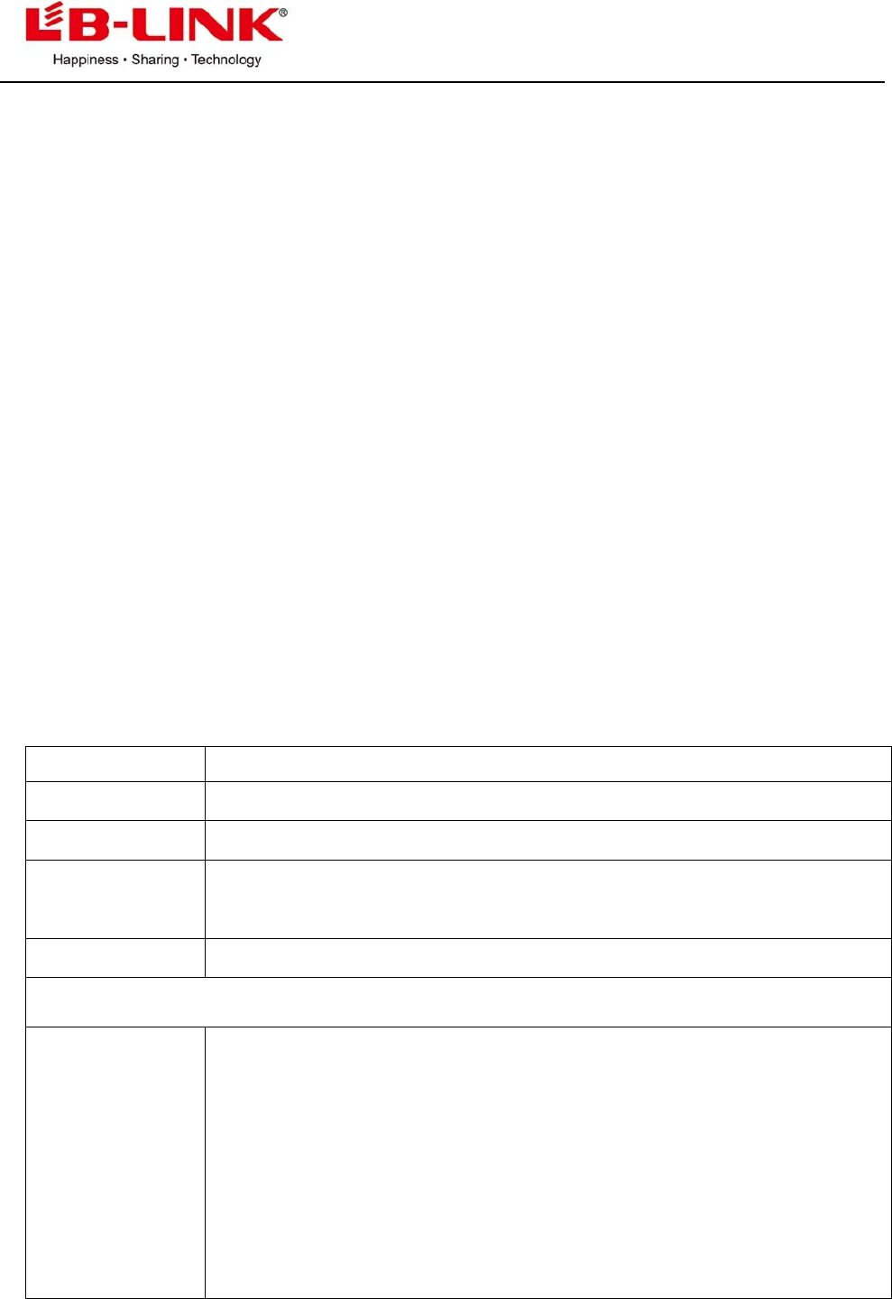
3 Features
Feature Implementation
Power supply VCC3.3V +-0.2V 220MA
Clock source 40MHz
Temperature
range
Work temperature:-20ºC---70ºC
Storage temperature -55°C ~ +125°C
Package SMT 6 pins
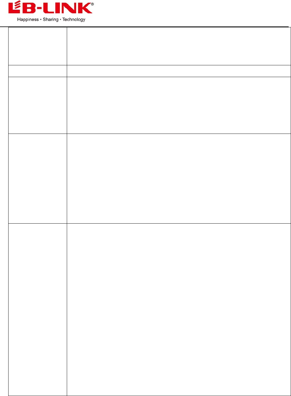
WLAN features
General features ■CMOS MAC, Baseband PHY, and RF in a single chip for IEEE
802.11b/g/n compatible WLAN
■Complete 802.11n solution for 2.4GHz band
■72.2Mbps receive PHY rate and 72.2Mbps transmit PHY rate using 20MHz
bandwidth
■150Mbps receive PHY rate and 150Mbps transmit PHY rate using 40MHz
bandwidth
B‐LINKELECTRONICCO.,LTDinshenzhen
3
■Compatible with 802.11n specification
■Backward compatible with 802.11b/g devices while operating in 802.11n
mode
Host Interface Co
m
plies with USB Specification Revision 2.0
Standards
Supported
■IEEE 802.11b/g/n compatible WLAN
■IEEE 802.11e QoS Enhancement (WMM)
■IEEE 802.11h TPC, Spectrum Measurement
■802.11i (WPA, WPA2). Open, shared key, and pair-wise key
authentication services
WLAN MAC
Features
■Frame aggregation for increased MAC efficiency (A-MSDU, A-MPDU)
■Low latency immediate High-Throughput Block Acknowledgement
(HT-BA)
■PHY-level spoofing to enhance legacy compatibility
■Power saving mechanism
■Channel management and co-existence
■Transmit Opportunity (TXOP) Short Inter-Frame Space (SIFS) bursting for
higher multimedia bandwidth
WLAN PHY
Features
■IEEE 802.11n OFDM
■One Transmit and one Receive path (1T1R)
■20MHz and 40MHz bandwidth transmission
■Short Guard Interval (400ns)
■DSSS with DBPSK and DQPSK, CCK modulation with long and short
preamble
■OFDM with BPSK, QPSK, 16QAM, and 64QAM modulation.
Convolutional Coding Rate: 1/2, 2/3, 3/4, and 5/6
■Maximum data rate 54Mbps in 802.11g and 150Mbps in 802.11n
■Switch diversity for DSSS/CCK
■Hardware antenna diversity
■Selectable receiver FIR filters
■Programmable scaling in transmitter and receiver to trade quantization
noise against increased probability of clipping Fast
■receiver Automatic Gain Control (AGC)
■On-chip ADC and DAC
B‐LINKELECTRONICCO.,LTDinshenzhen
4
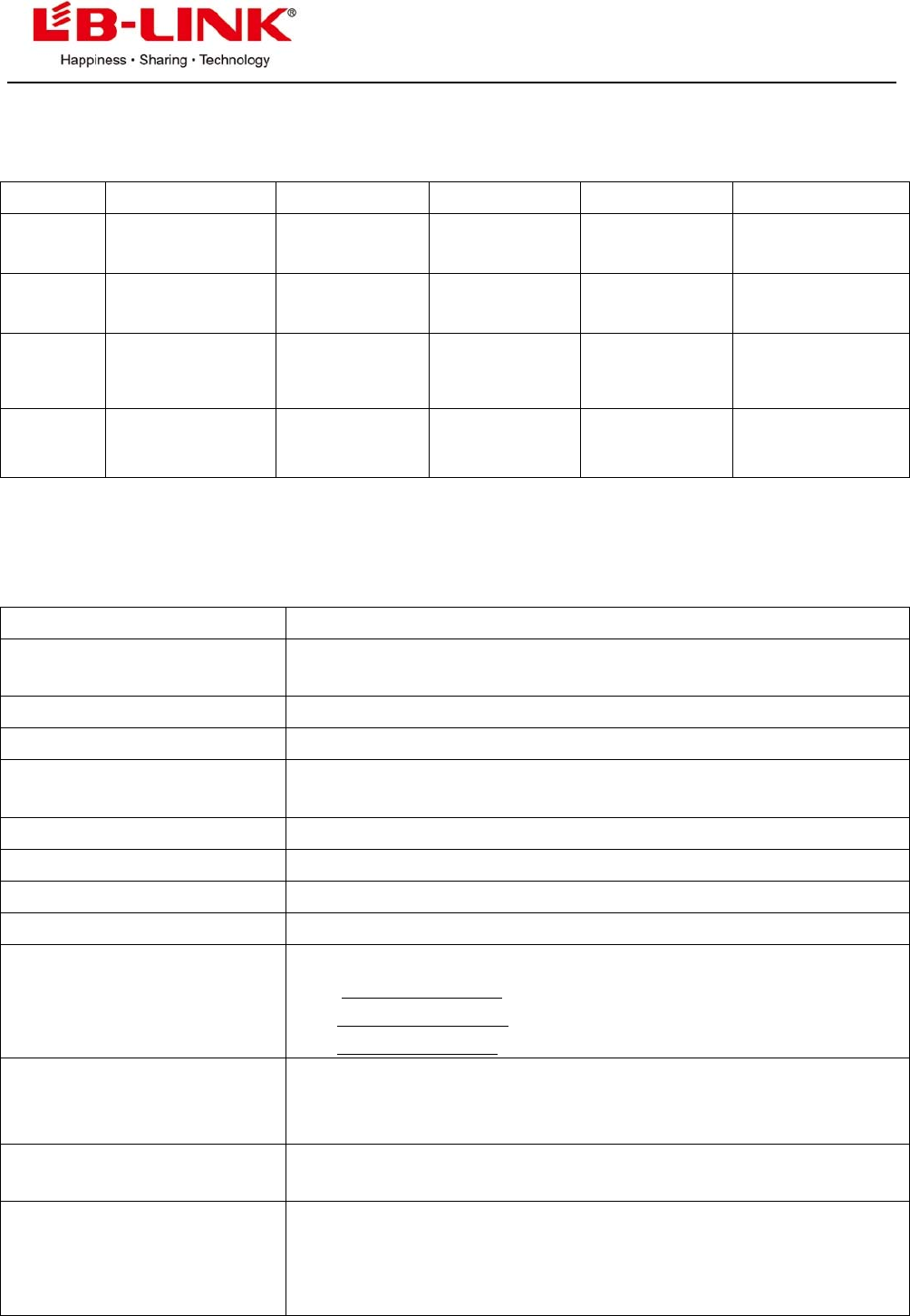
4 DC Characteristics
Symbol Parameter Minimum Typical Maximum Units
VD33A,
VD33D
3.3V I/O
Supply Voltage
3.0 3.3 3.6 v
VD12A,
VD12D
1.2V Core
Supply Voltage
1.10 1.2 1.32 v
VD15A,
VD15D
1.5V Supply
Voltage
1.425 1.5 1.575 v
IDD33 3.3V Rating
Current
- -
600
mA
5 The main performance of product
Item Description
The supported protocol and
standard IEEE 802.11n, IEEE 802.11g,EE 802.11b
Interface type USB2.0
The range of frequency 2.4-2.484GHZ
The amount of working
Channel 1-11(America, Canada);1-13(China, Europe);1-14(Japan)
Data Modulation OFDM/DBPSK/DQPSK/CCK
Working Mode Infrastructure, Ad-Hoc
The transmitting rate 135/54/48/36/24/18/12/9/6 /1M(self-adapting)
Spread spectrum DSSS
Sensitivity @PER
54/135M:-74dBm@10%PER,
11M:-85dBm@8%PER
6M: -88dBm@10%PER ,
1M: -90dBm@8%PER
RF Power
135M:15dBM,
54M:15dBM,
11M:19dBM
Throughput 80Mbps(external 2dbi antenna ,damping 50dbm in Shielding box )
The connect type of
Antenna
Connect to the external antenna through the half hole,Connectto
theexternalantennathroughthehalfhole,Theantennaandother
interfacegetconnectedtotheexternaldevicesbytheedgehalfa
circleweldingplate
B‐LINKELECTRONICCO.,LTDinshenzhen
5
LED indicator status indicator
The transmit distance Indoor 100M, Outdoor 300M, according the local environment
Working Power consumption 68MA
MENS(L*W*H) 12.3MM*12.9MM*0.6MM
The chipset model RTL8188EUS
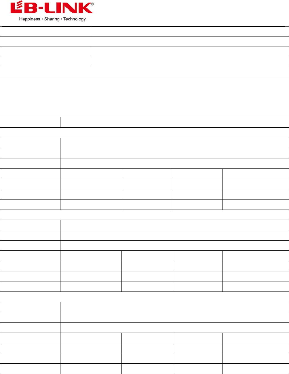
6 DC/RF characteristics
Terms Contents
Specification : IEEE802.11b
Mode DSSS / CCK
Frequency 2412 – 2484MHz
Data rate 1, 2, 5.5, 11Mbps
DC Characteristics min Typ. max. unit
TX mode 257 263 271 mA
Rx mode 80 82 84 mA
Standby mode 140 145 146 uA
Specification : IEEE802.11g
Mode OFDM
Frequency 2412 - 2484MHz
Data rate 6, 9, 12, 18, 24, 36, 48, 54Mbps
DC Characteristics min Typ. max. unit
TX mode 244 245 245 mA
Rx mode 88 89 89 mA
Standby mode 143 145 146 uA
Specification : IEEE802.11n
Mode OFDM
Frequency 2412 - 2484MHz
Data rate 6.5, 13, 19.5, 26, 39, 52, 58.5, 65Mbps
DC Characteristics min Typ. max. unit
TX mode 201 207 214 mA
Rx mode 90 93 94 mA
Standby mode 144 145 146 uA
B‐LINKELECTRONICCO.,LTDinshenzhen
6
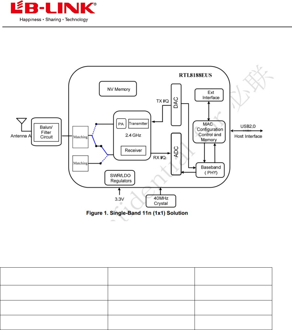
7 The block diagram of product principle
8 The supported platform
Operating System CPU Framework Driver
WIN2000/XP/VISTA/WIN7 X86 Platform Enable
LINUX2.4/2.6 ARM, MIPSII Enable
WINCE5.0/6.0 ARM ,MIPSII Enable
B‐LINKELECTRONICCO.,LTDinshenzhen
7
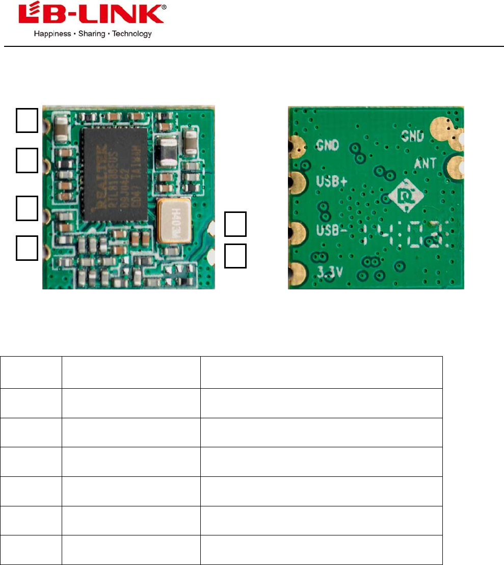
9 The definition of product Pin
Top and bottom view of BL-8188-EU1
Pin No: TYPE Description
1 P DC :3.3V
2 I/O UDM-
3 I/O UDP+
4 P GND
5 P GND
6 O ANT
1
2
3
4
6
5
B‐LINKELECTRONICCO.,LTDinshenzhen
8
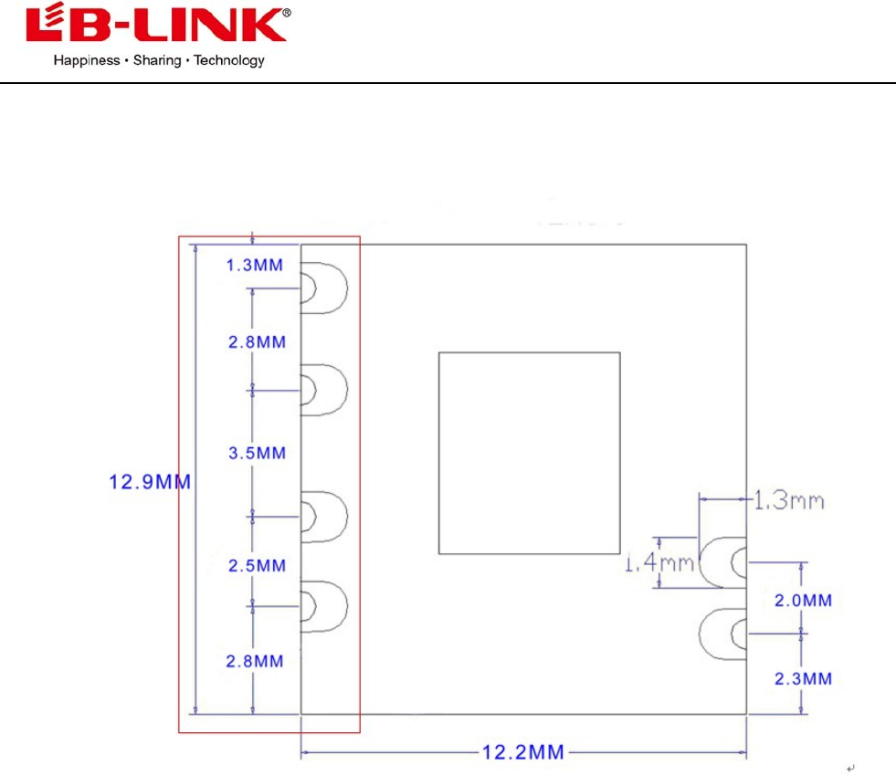
10 The Structure and Size of product
BL-R8188-EU1
B‐LINKELECTRONICCO.,LTDinshenzhen
9
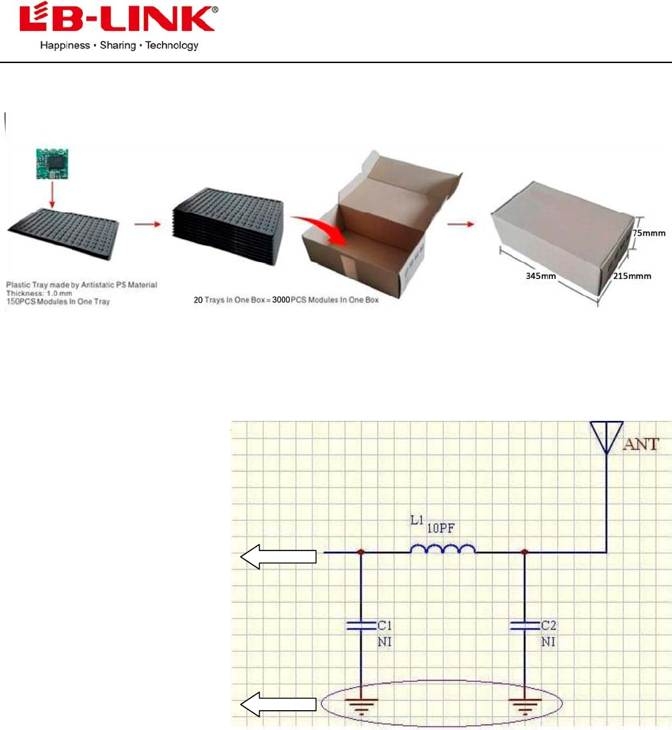
11:Packing
12:The 6th Pin connect to antenna, please refer to design demand
Connect to the 6th pin of Module
Connect to the 5th pin of Module
a) The current of 3.3V power supply must be >300mA, its ripple wave must be <30mV. The GND
pins of module and external antenna need to be an incorporated part. The ground plane should be
larger, module and antenna should keep far away from interference source.
b) The sixth pin is 2.4G high frequency output, coplanar impedance of layout line between this pin
to antenna interface should be 50Ω, we suggest use arc line or straight line, and beside the line
there will be ground plane that its length as shout as possible, the longest length is no more than
50mm.
c) L1, C1, C2 constitute a π-type network that we preset, please make it close to antenna interface,
this π-type network is used to match the antenna parameters and control the radiation. It should
be adjusted according to the real condition when being used. Normally you can only mount L1
that its parameters are: 10pF, NP0 material. No need C1 and C2
B‐LINKELECTRONICCO.,LTDinshenzhen
10
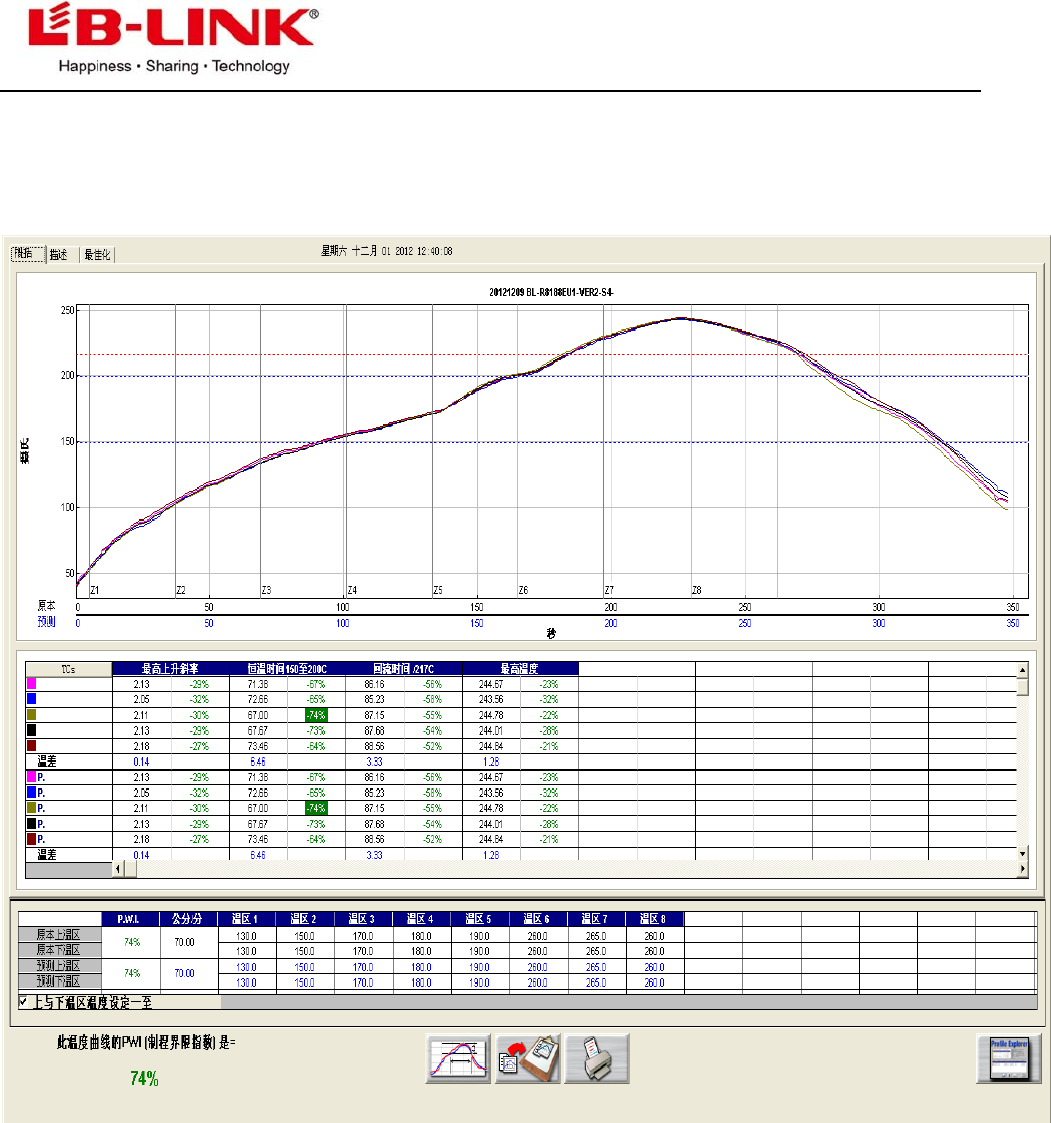
13:Tipcial Solder Reflow Profile