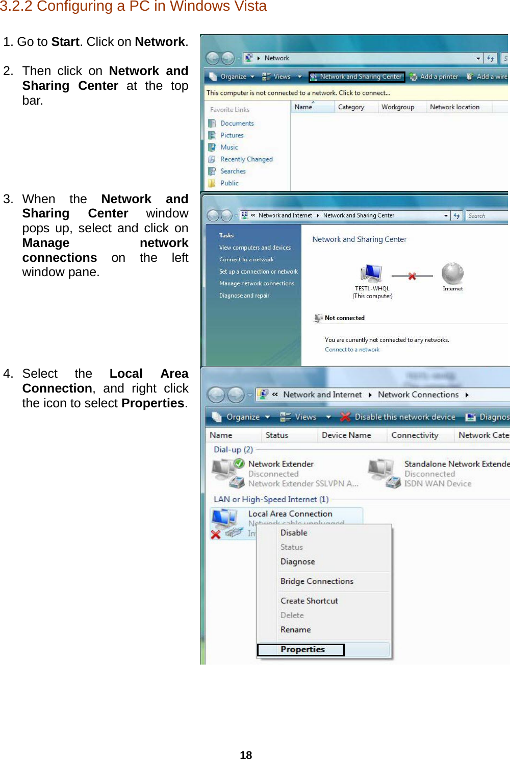
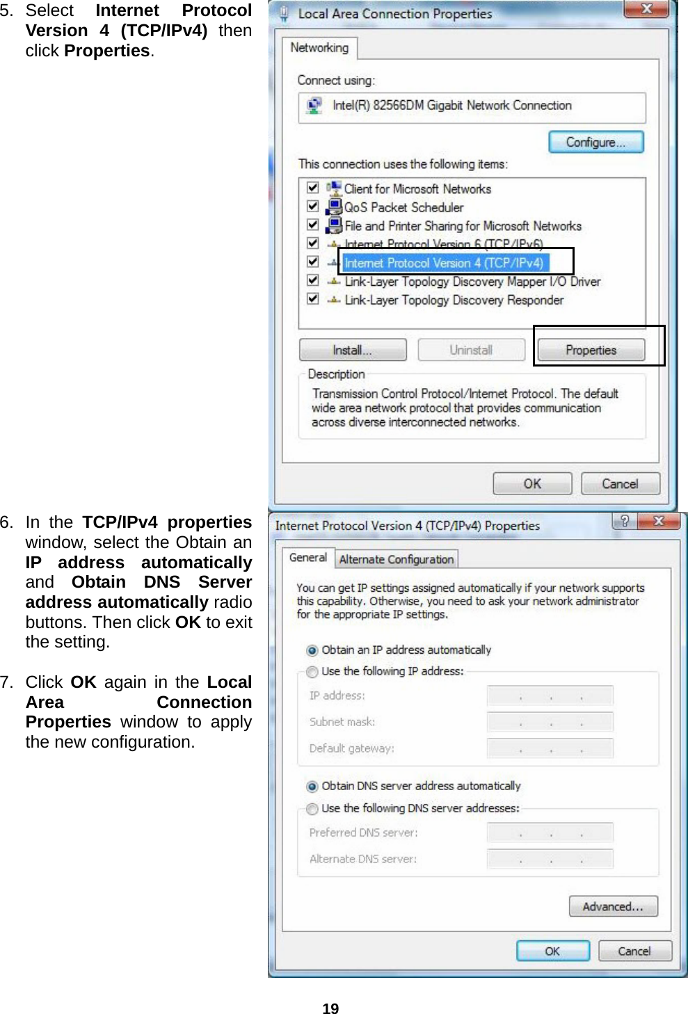
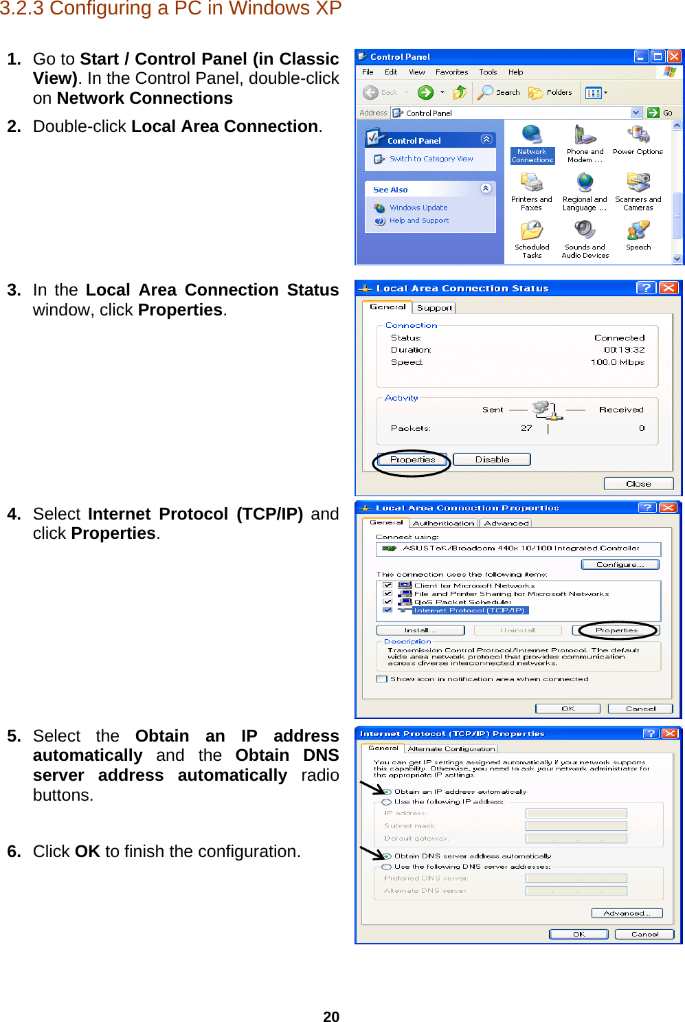
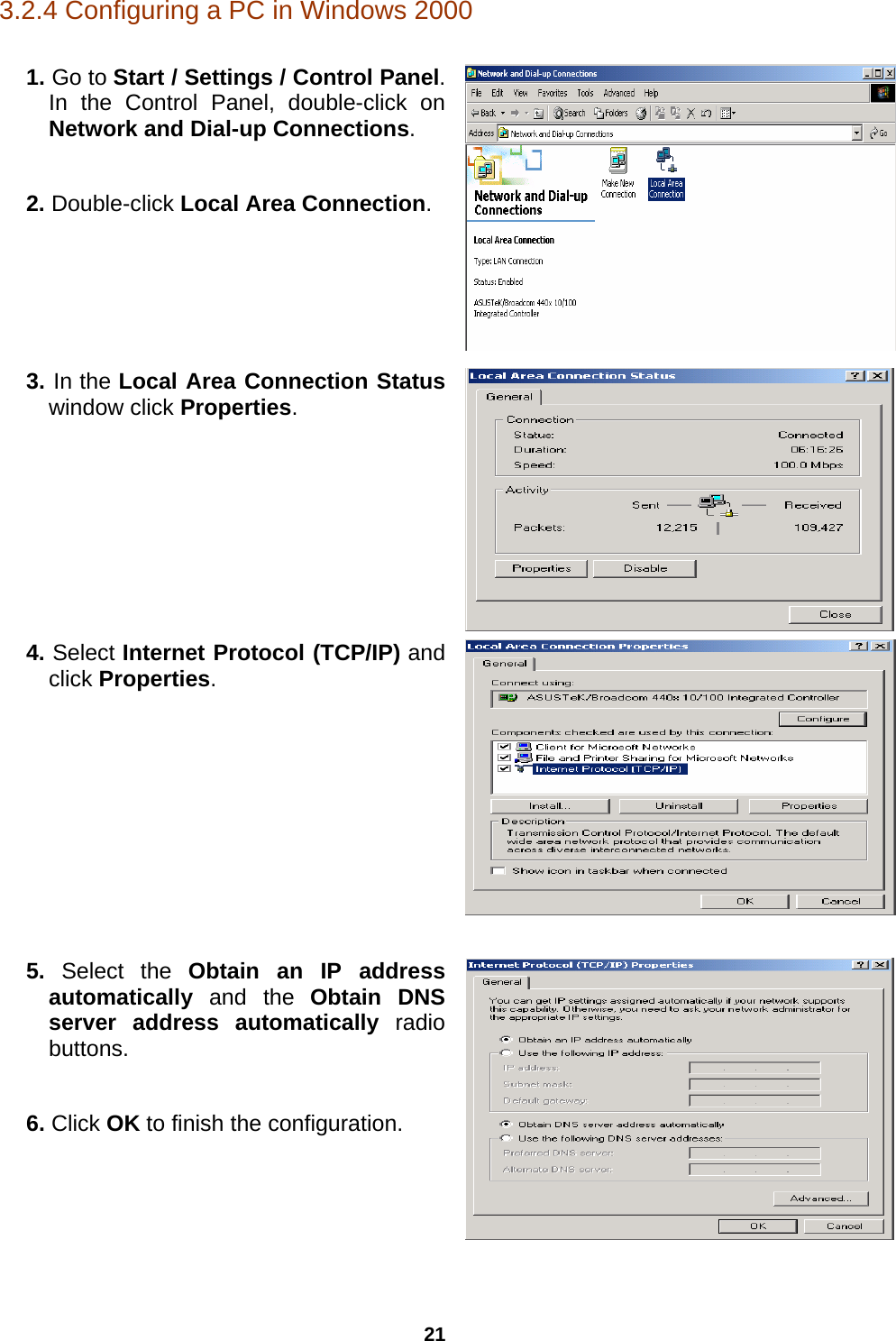
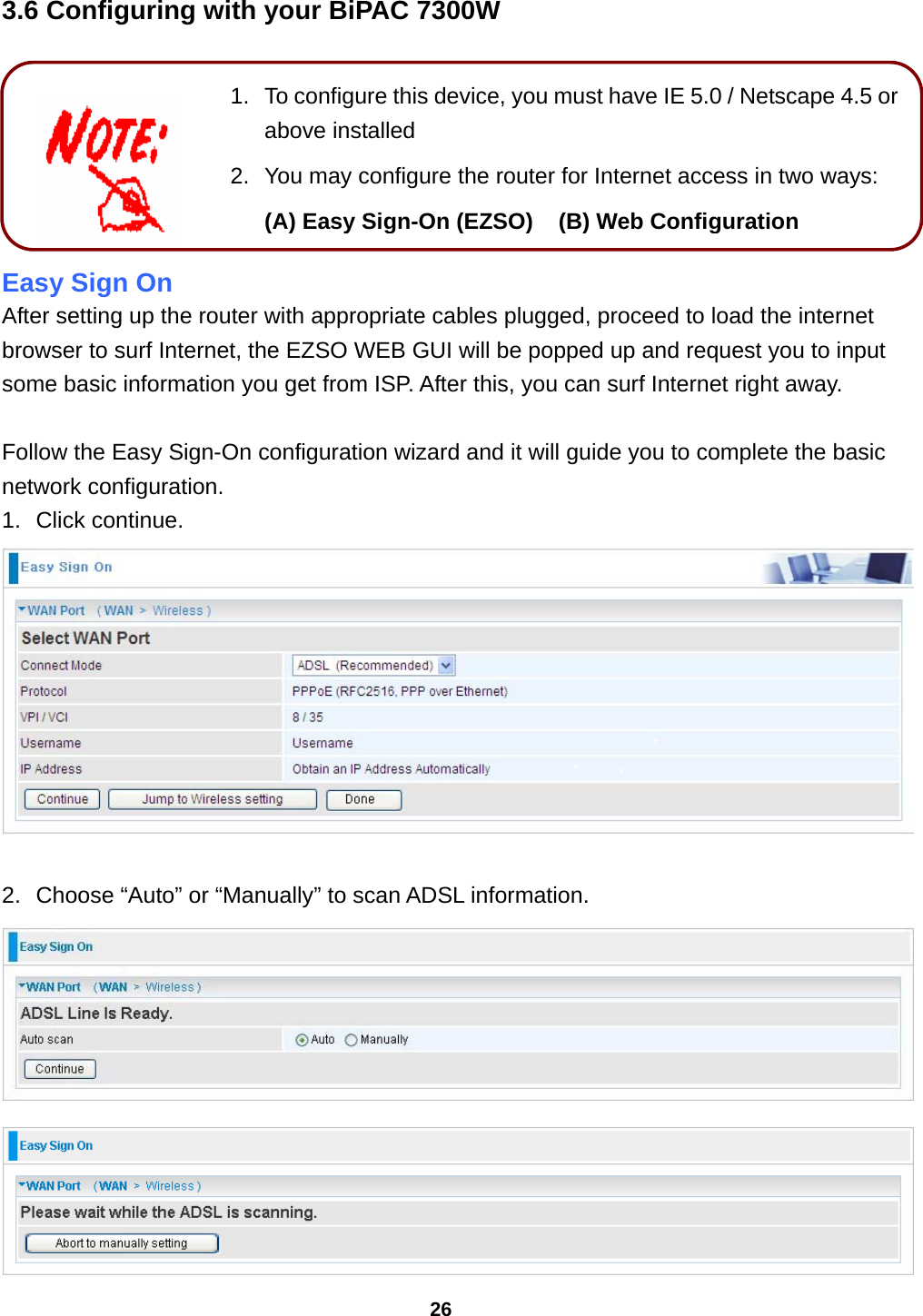
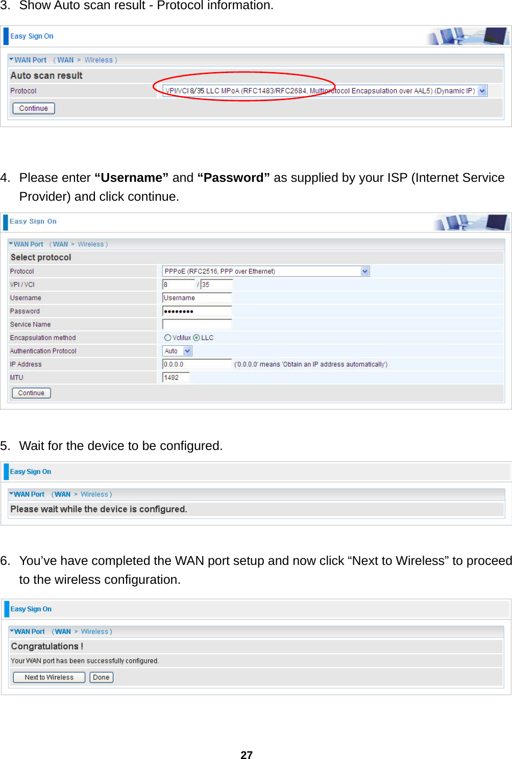
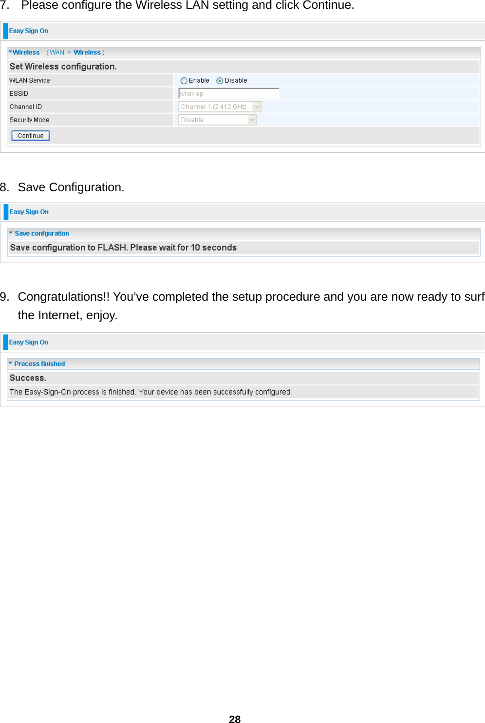
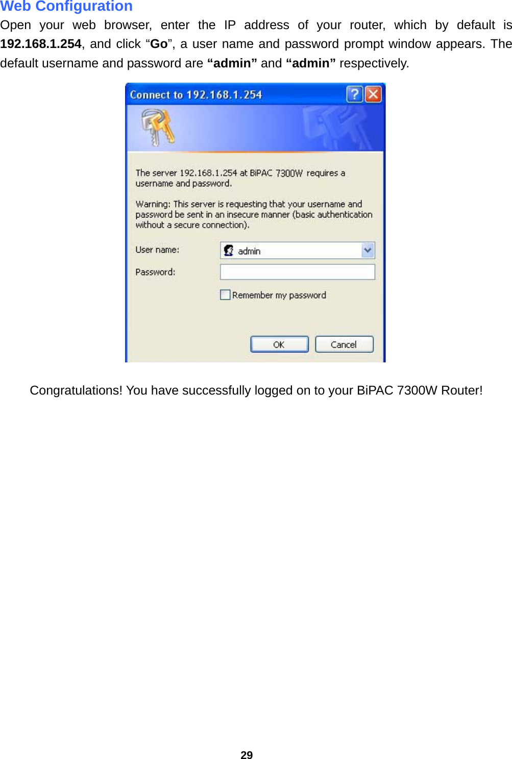
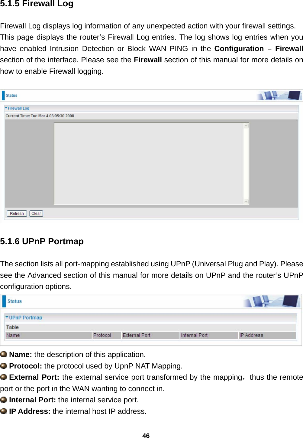
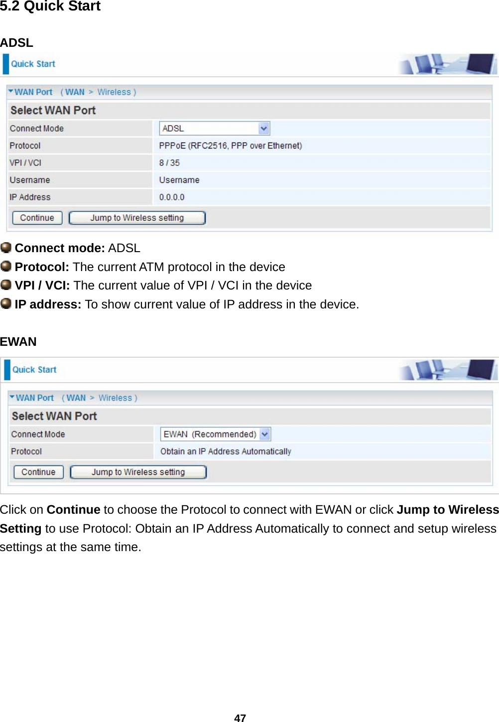
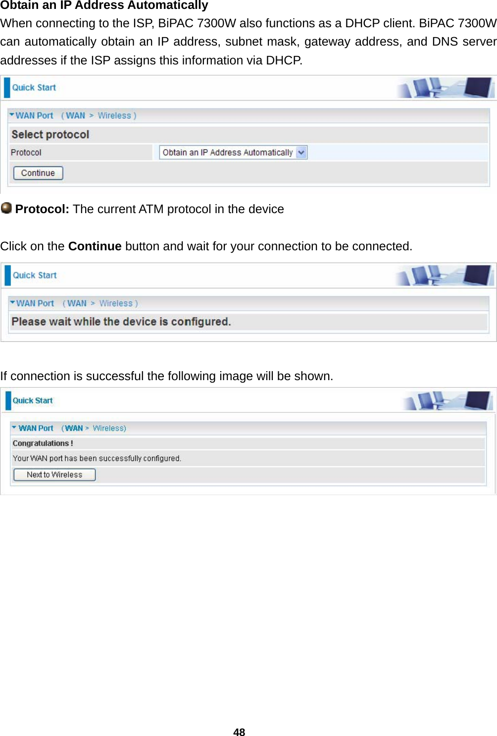
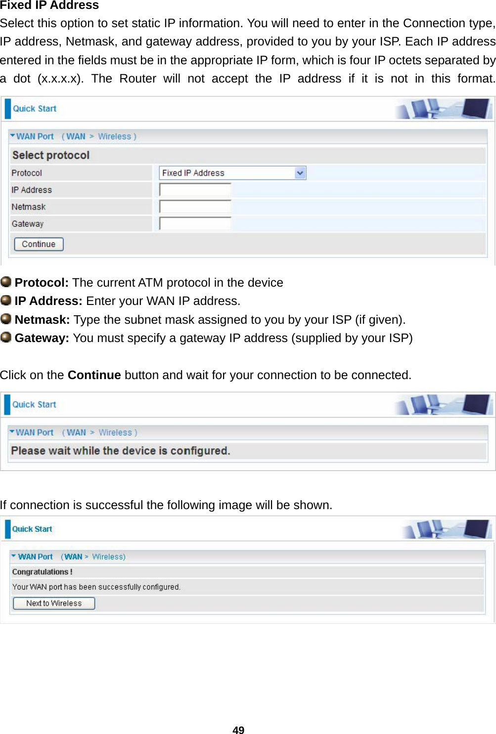
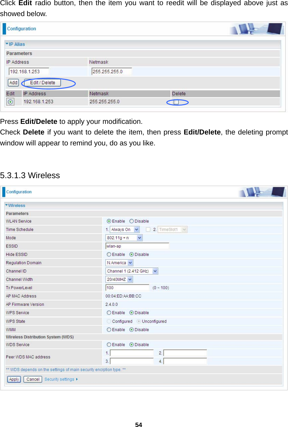
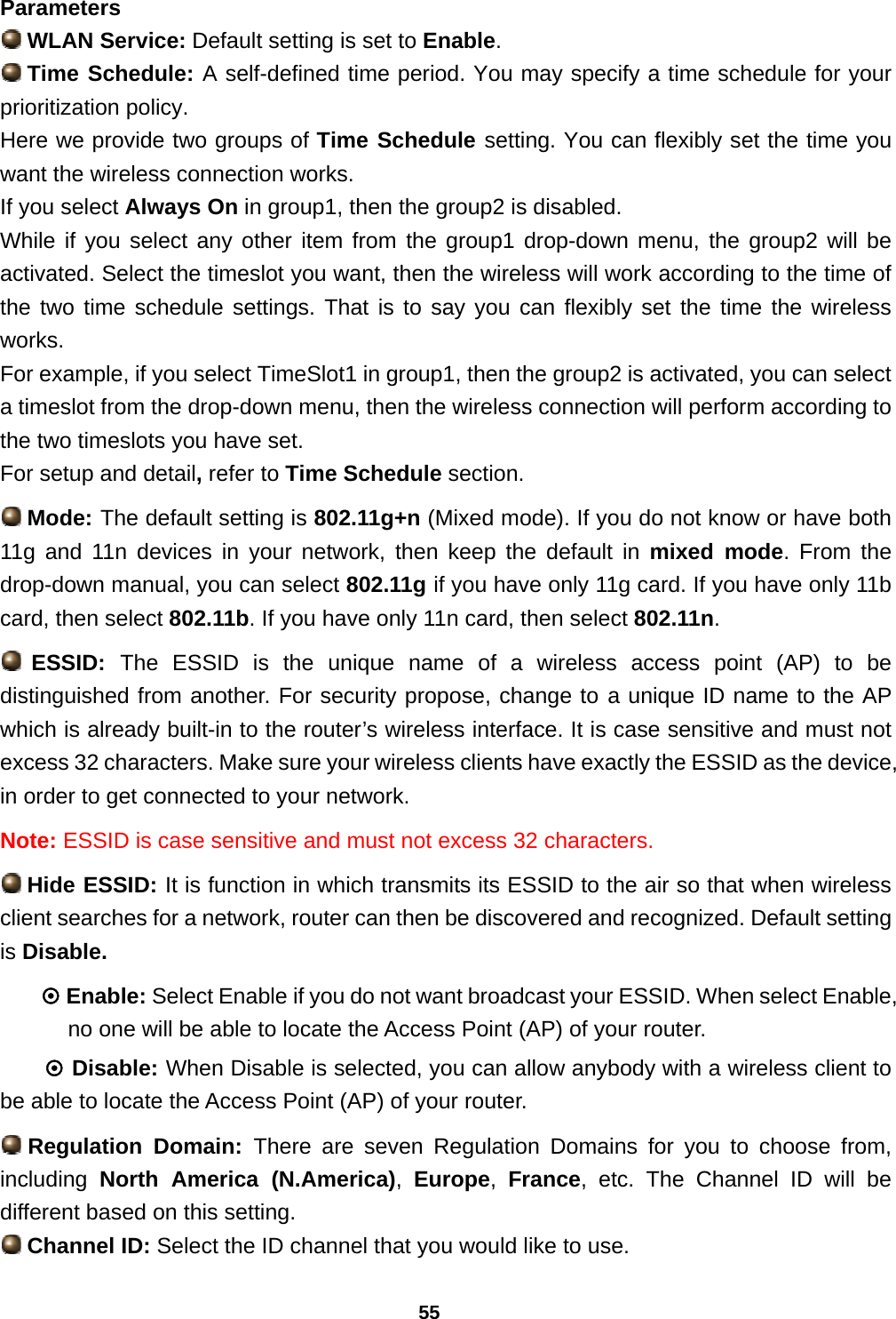
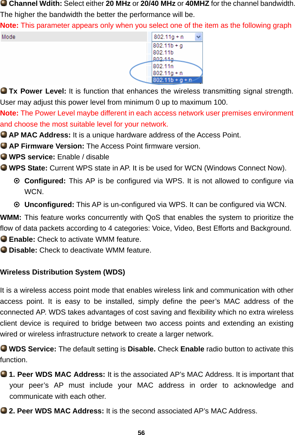
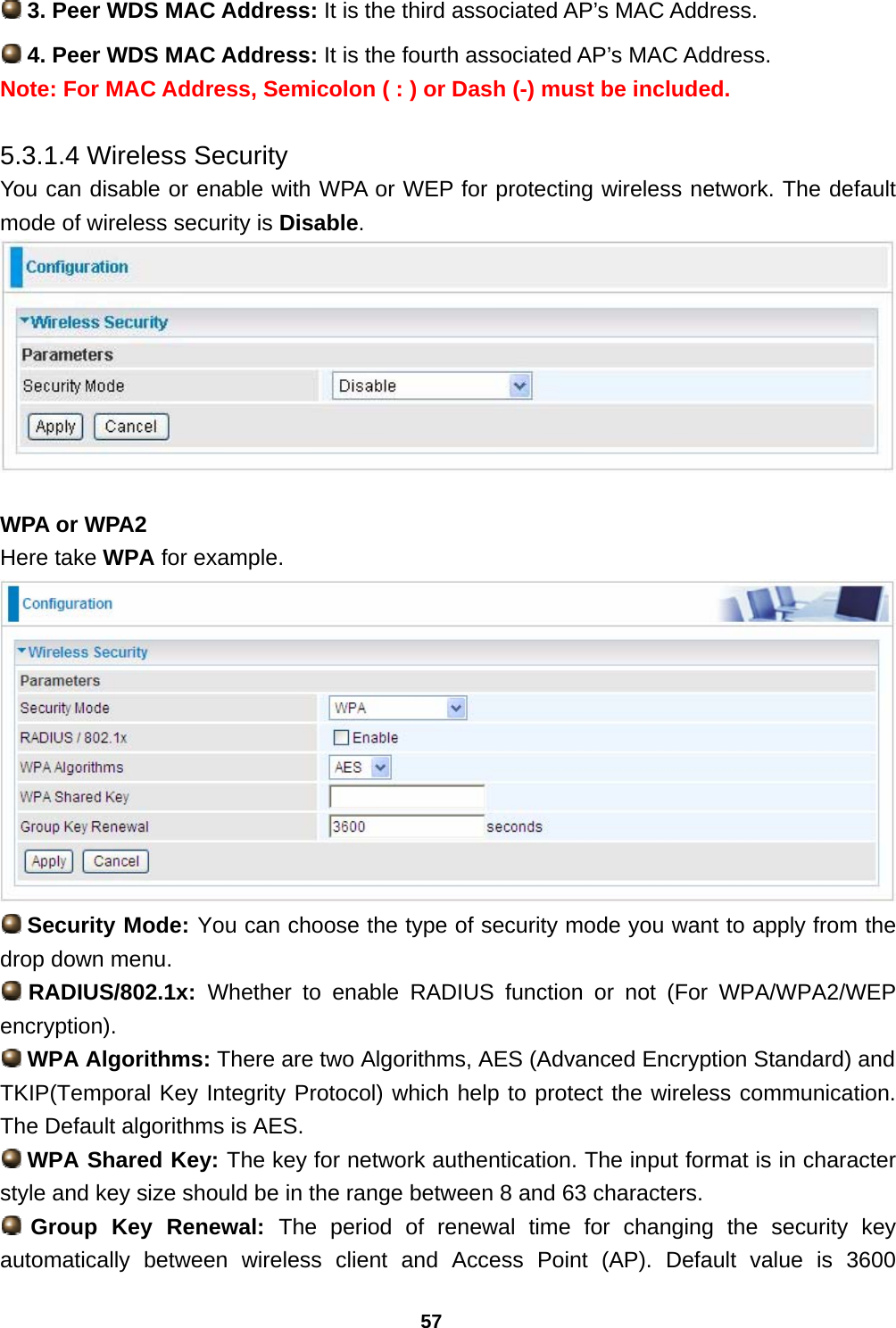
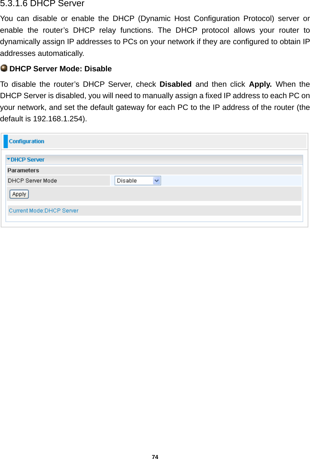
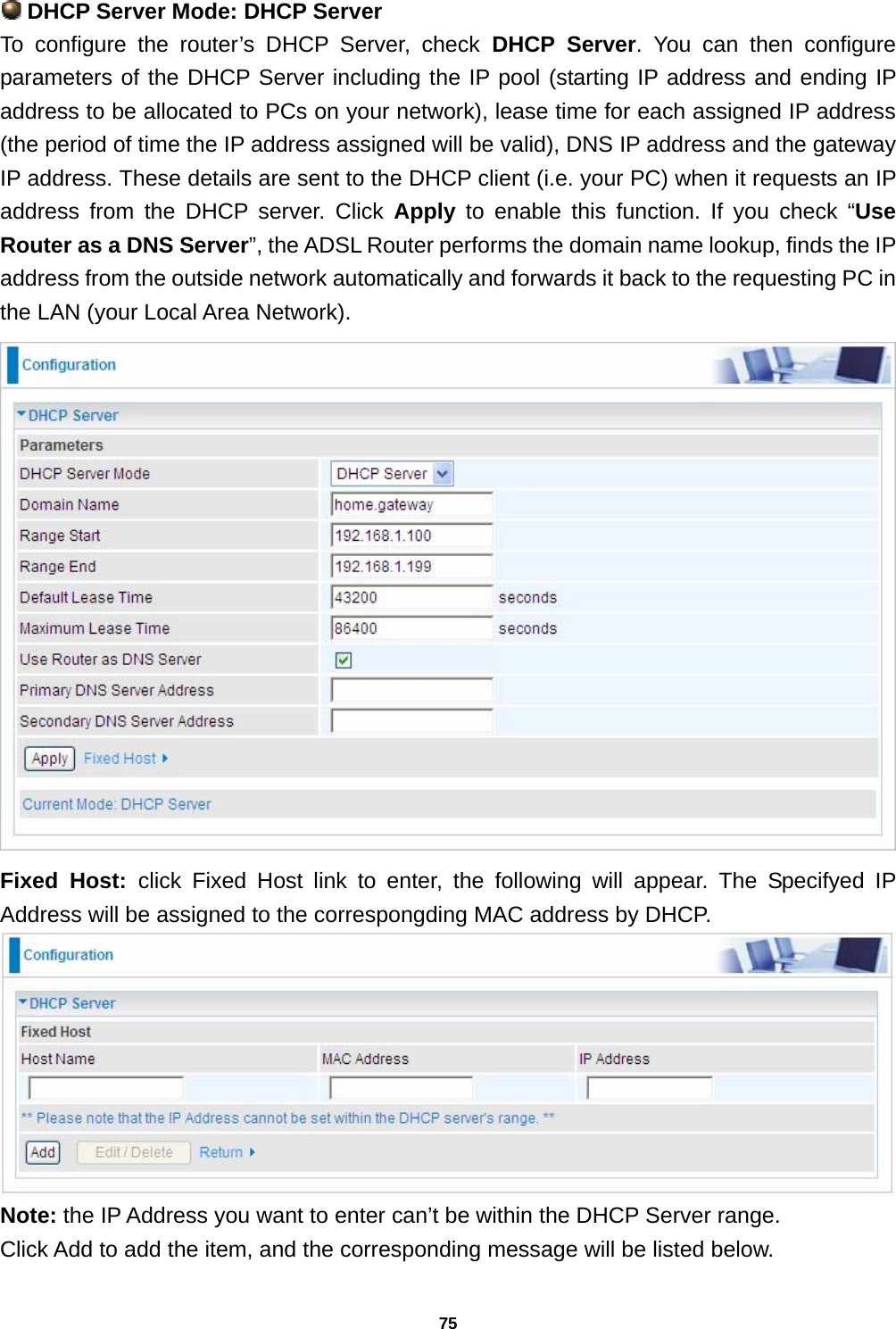
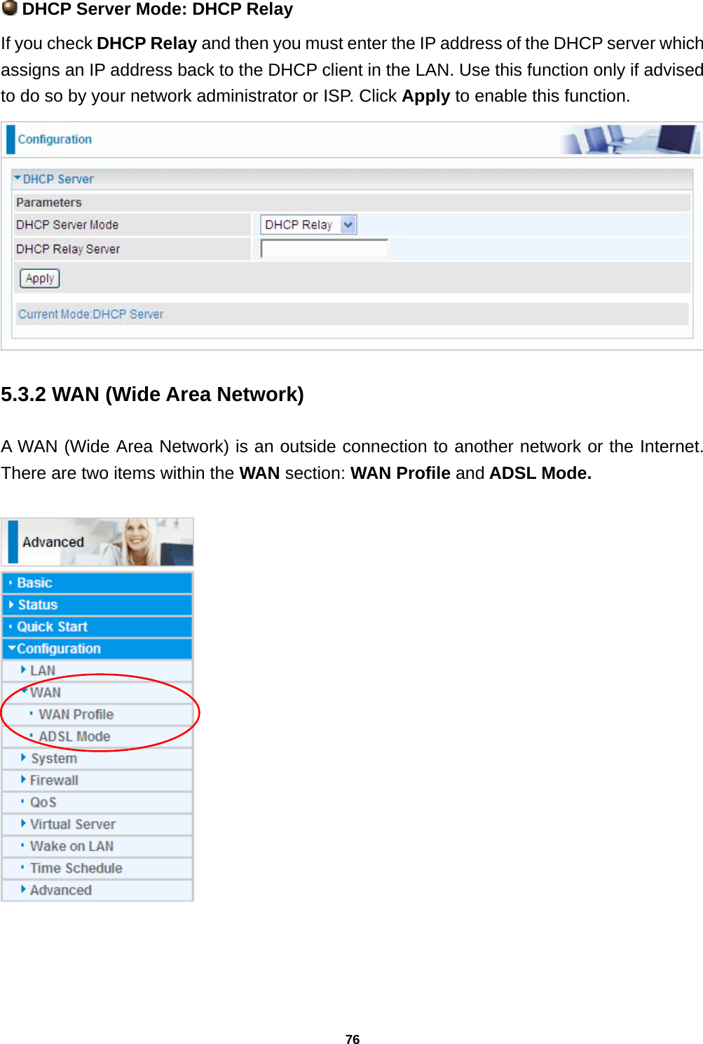
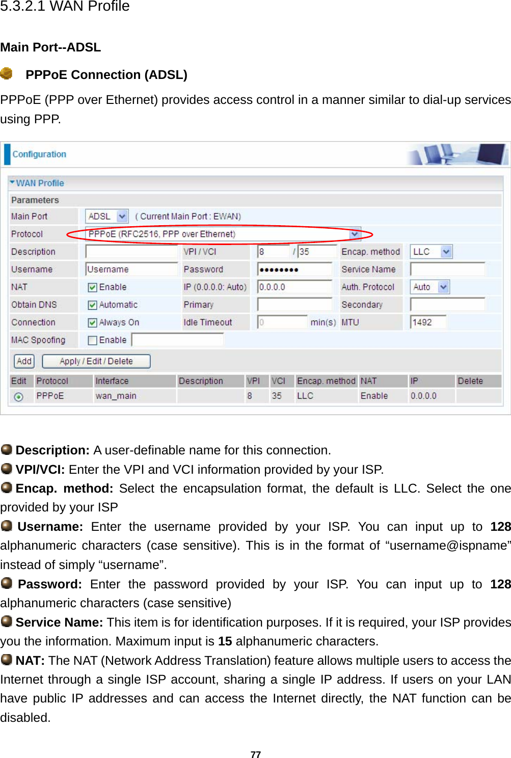
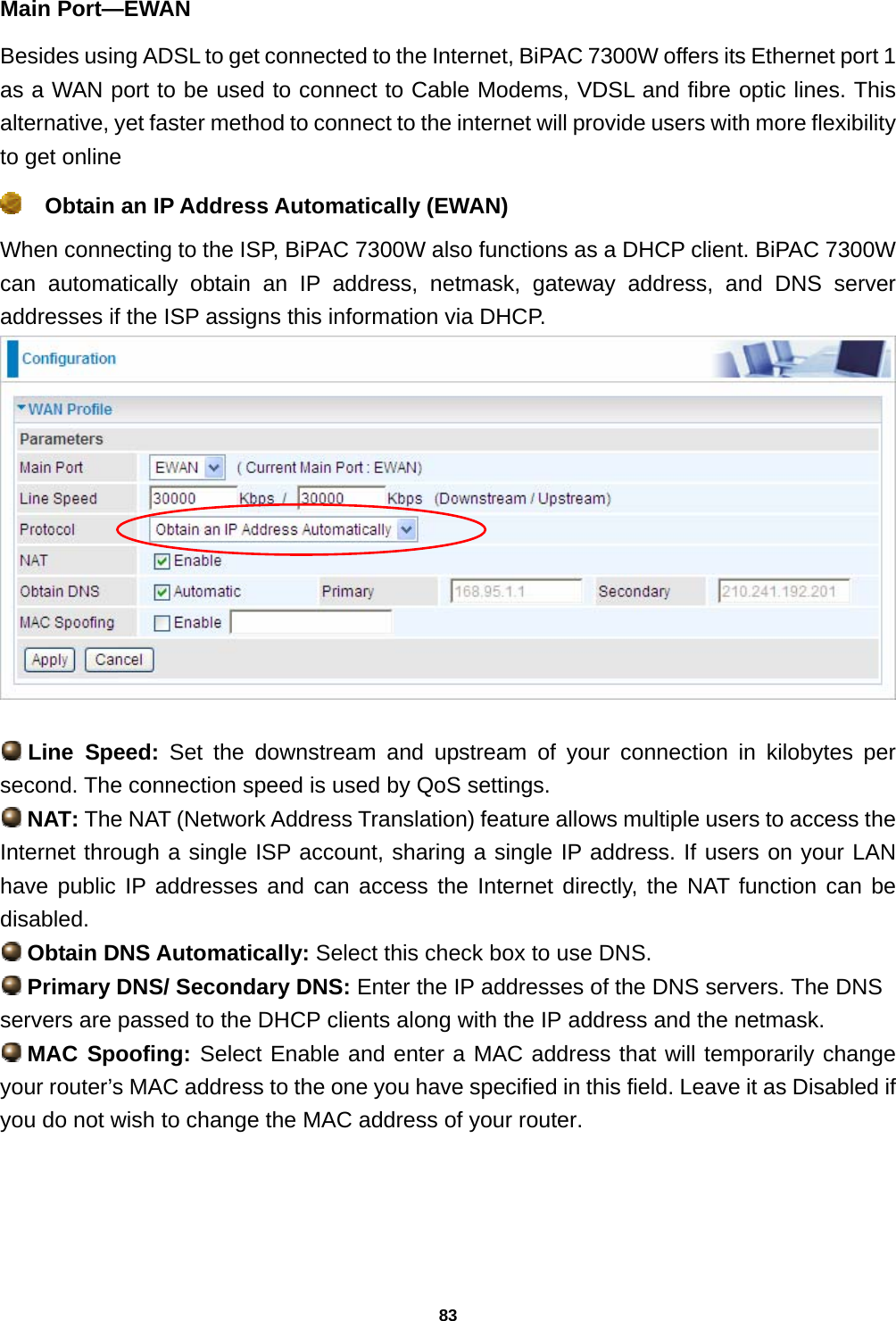
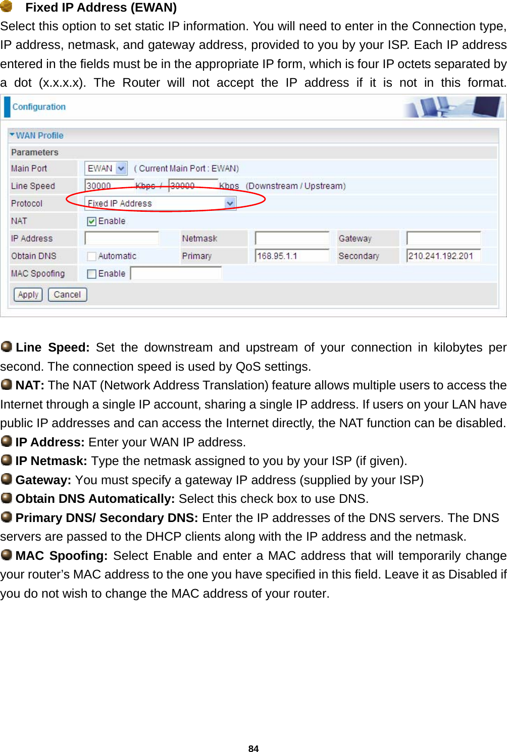
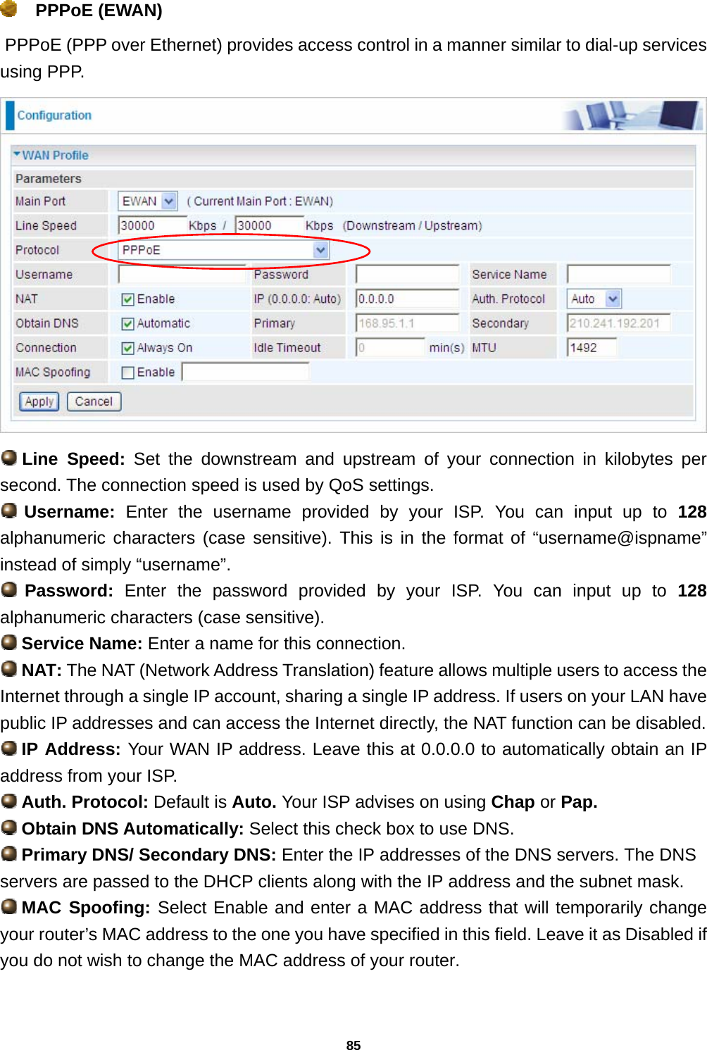
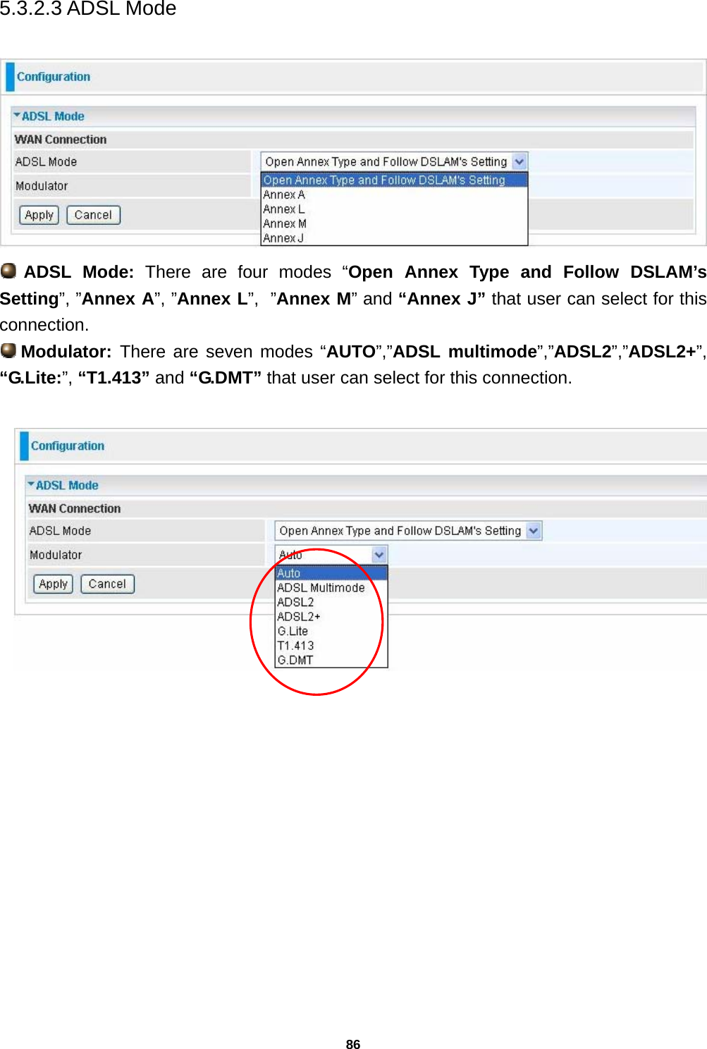
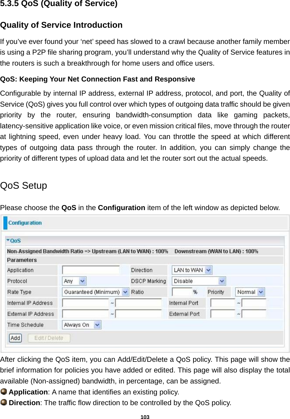
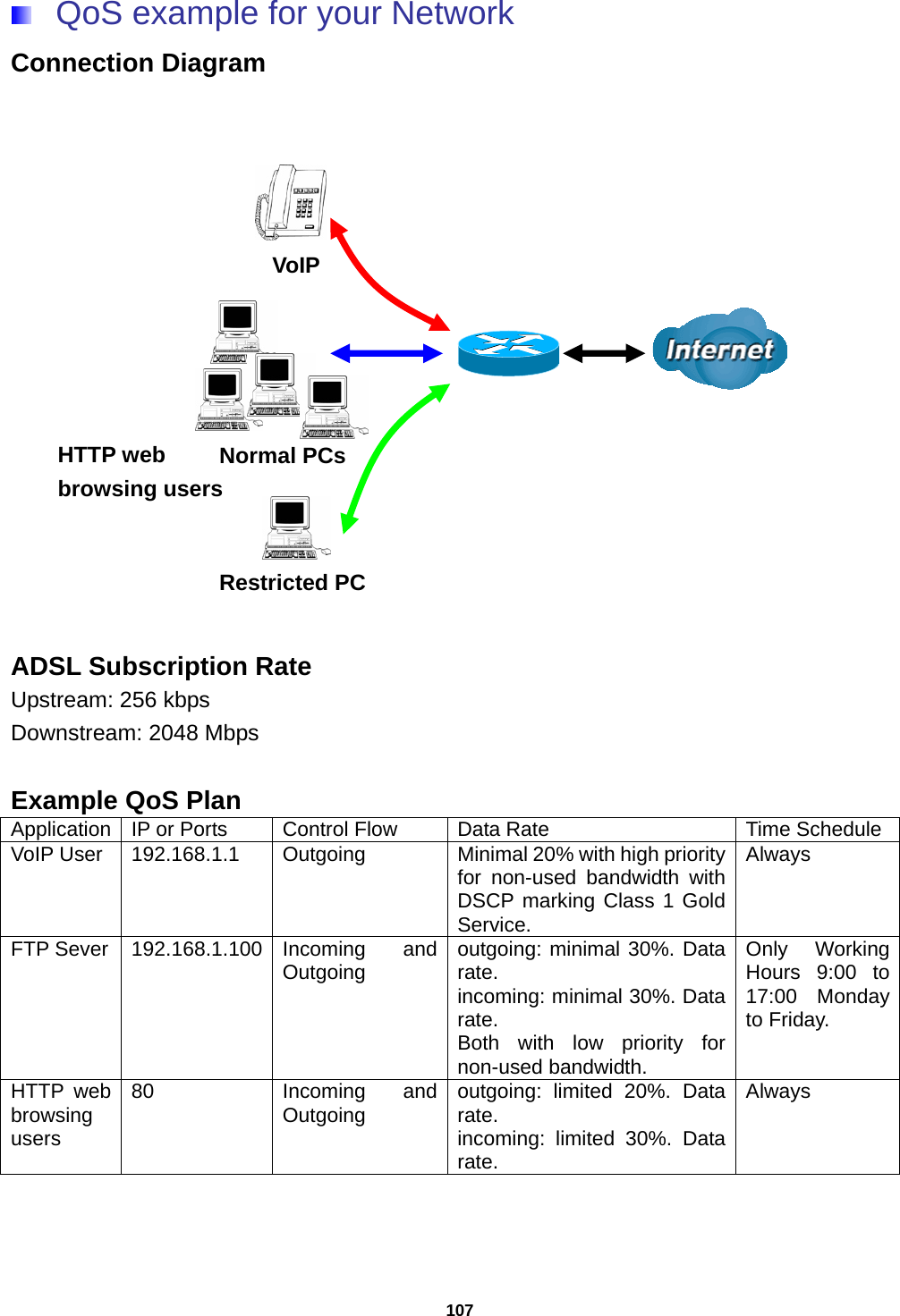
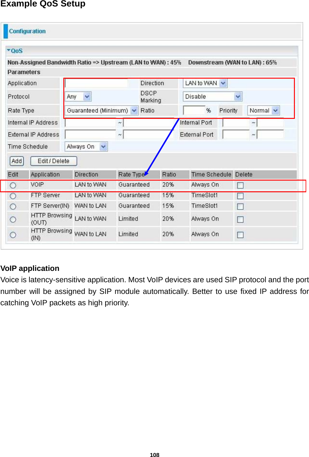
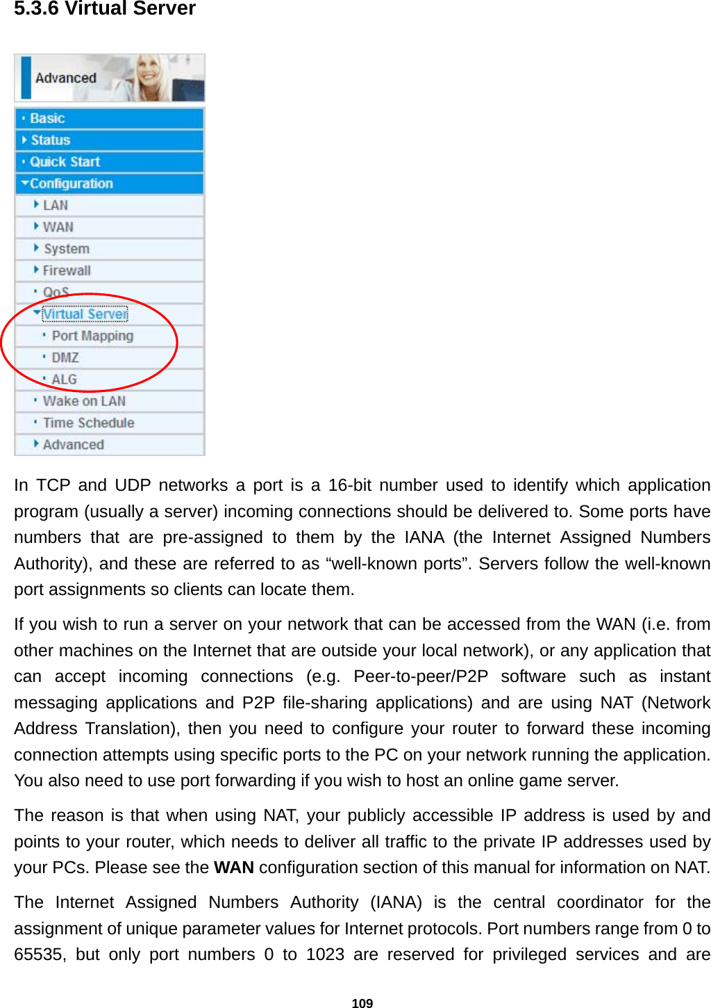
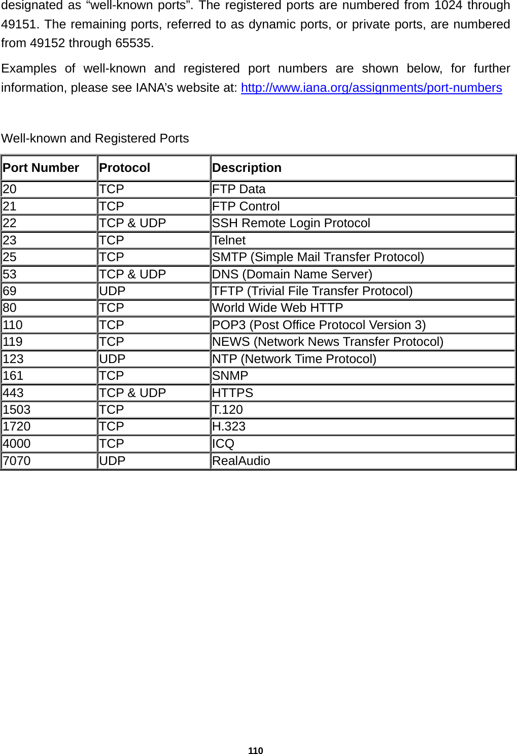
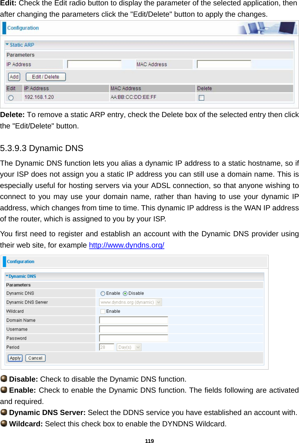
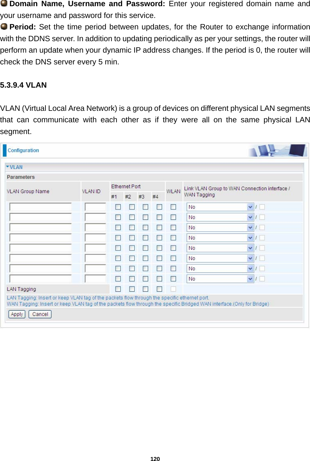
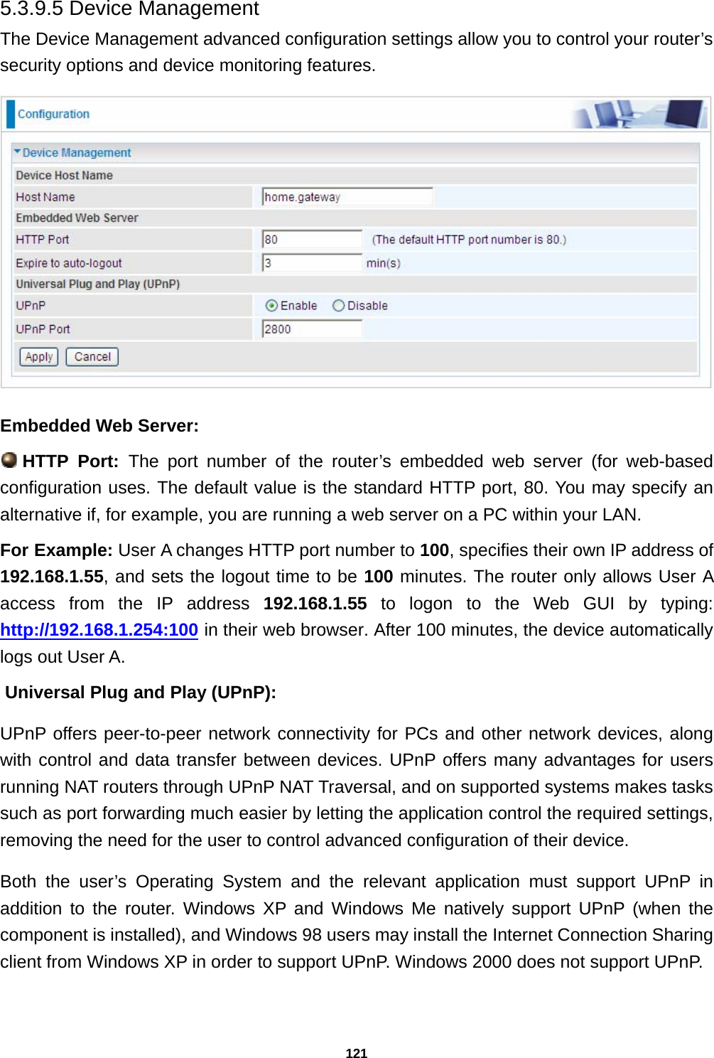
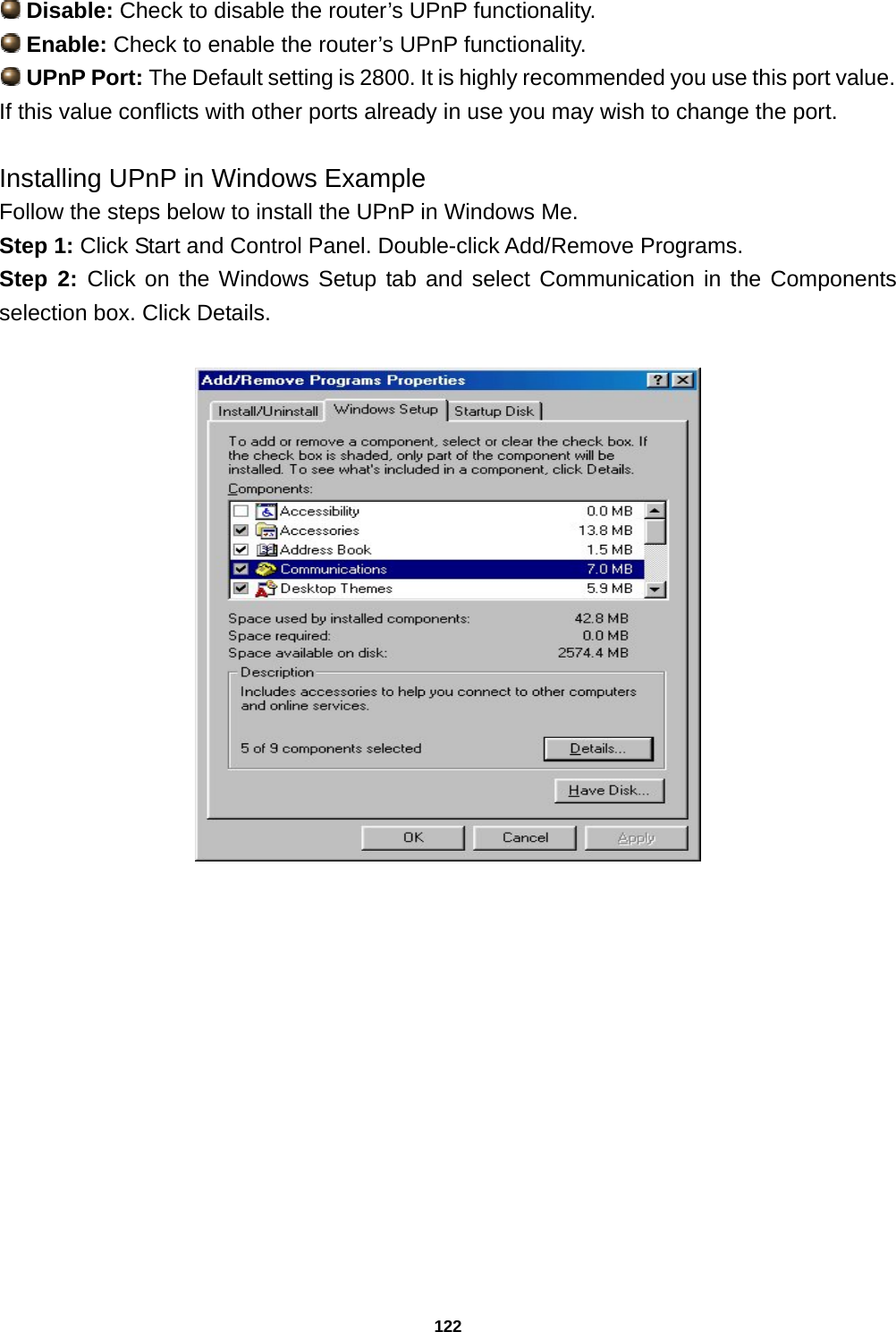
Billion Electric 7300WX Wireless-N ADSL2+ Firewall Router User Manual User MAnual
Billion Electric Co., Ltd. Wireless-N ADSL2+ Firewall Router User MAnual
UserManual.wiki
>
Billion Electric
>
7300WX User Manual
User MAnual
Navigation menu
Upload a User Manual
Namespaces
Wiki Guide
HTML
PDF
Info
Views
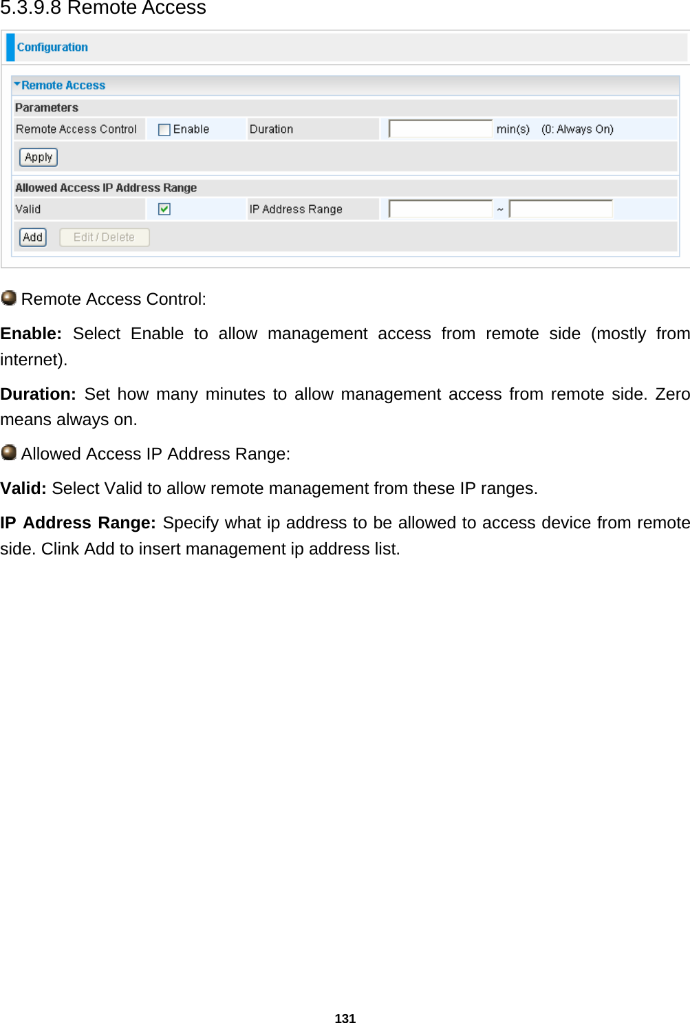
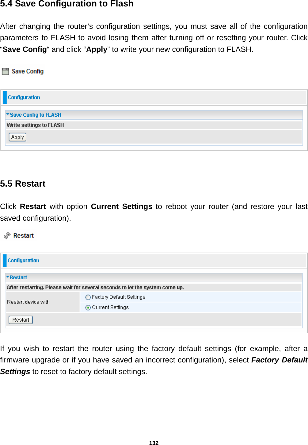
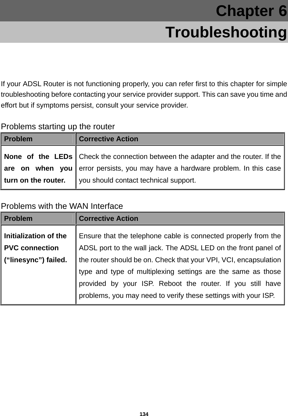
User Manual
Discussion / Help
Navigation