Billion Electric BIL-2073N-R Wireless-N HomePlug AV200 Ethernet Adapter User Manual Use s Manual

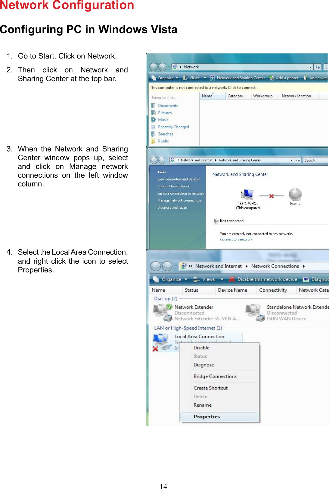
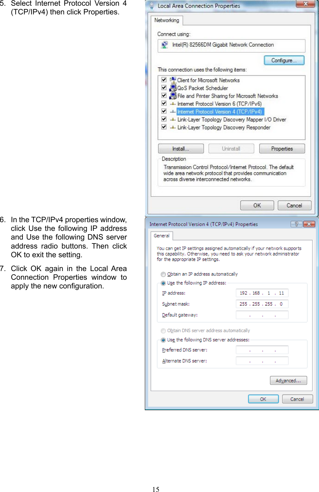
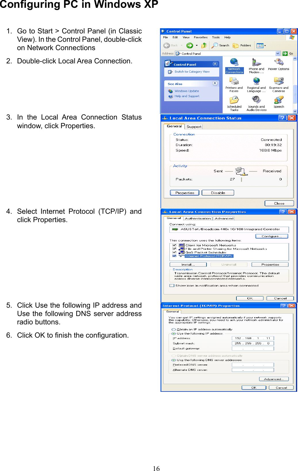
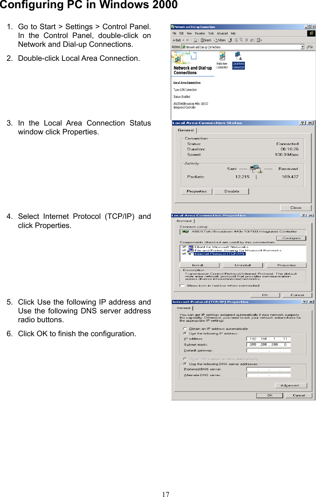
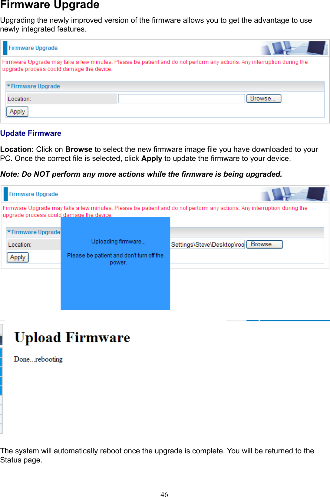
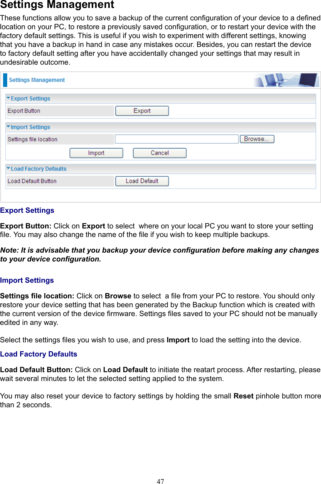
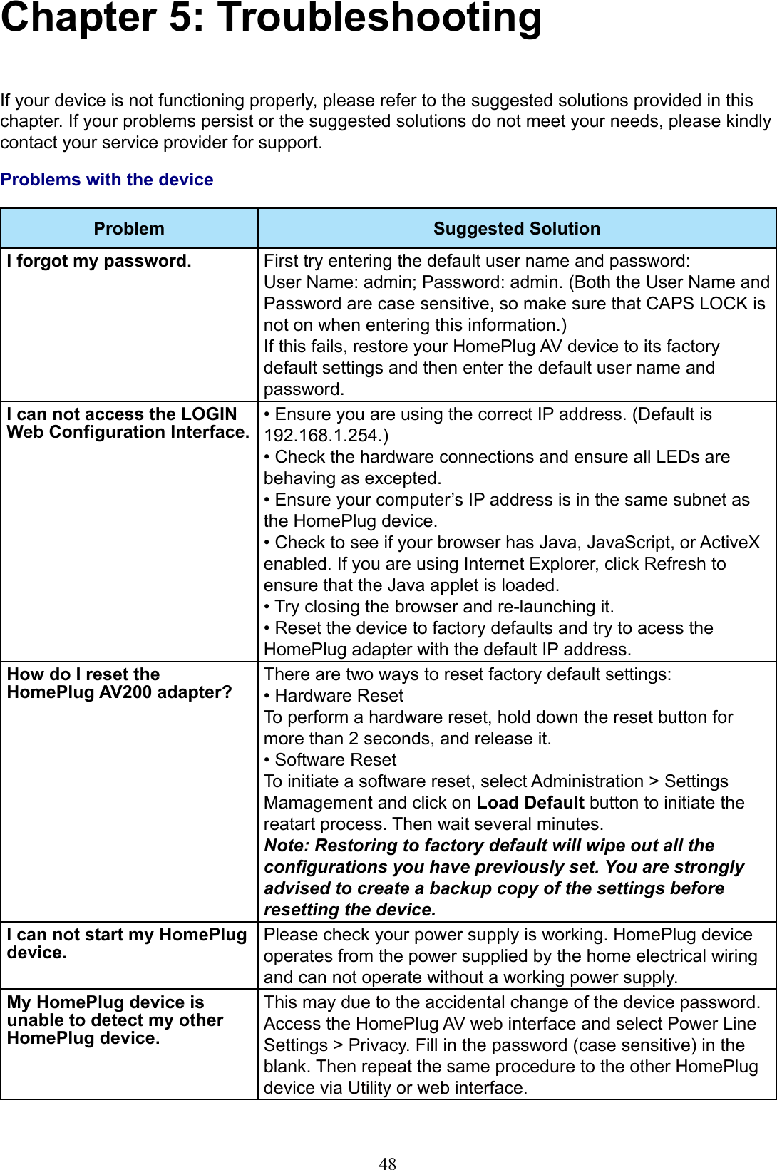
Billion Electric Co., Ltd. Wireless-N HomePlug AV200 Ethernet Adapter Use s Manual

Use's Manual

Wireless-N HomePlug AV 200 Wall Plug Ethernet AdapterUser ManualLast revised April 2009
Safety WarningsDo not use the adapter in high humidity or high temperature environment.1. Do not open or repair the case yourself.2. Avoid using this product and all its accesories outdoor.3. Place the adapter on a stable surface.4. Only “HomePlug AV” compliant Powerline Communication (PLC) adapter for remote access is 5. necessary.Plug your HomePlug AV device directly to the AC outlet on the wall. It is best to avoid using 6. extension  power  cable  as  it  may  possess  noise  lter  or  surge  protector  functions  that  may cause interference that may impact the performance of the device.FCC StatementThis equipment has been tested and found to comply with the limits for a Class B digital device, pursuant to Part 15 of the FCC Rules. These limits are designed to provide reasonable protection against harmful interference in a residential installation.This equipment generates, uses and can radiate radio frequency energy and, if not installed and used in accordance with the instructions, may cause harmful interference to radio communications. However, there is no guarantee that interference will not occur in a particular installation. If this equipment does cause harmful interference to radio or television reception, which can be determined by turning the equipment off and on, the user is encouraged to try to correct the interference by one of the following measures:Reorient or relocate the receiving antenna.Increase the separation between the equipment and receiver.Connect the equipment into an outlet on a circuit different from that to which the receiver is connected.Consult the dealer or an experienced radio/TV technician for help.To assure continued compliance, any changes or modifications not expressly approved by the party responsible for compliance could void the user's authority to operate this equipment.(Example - use only shielded interface cables when connecting to computer or peripheral devices).Changes or modifications not expressly approved by the party responsible for compliance could void the user's authority to operate the equipment.This equipment complies with FCC RF radiation exposure limits set forth for an uncontrolled environment. This device and its antenna must not be co-located or operating in conjunction with any other antenna or transmitter.“To comply with FCC RF exposure compliance requirements, this grant is applicable to only Mobile Configurations. The antennas used for this transmitter must be installed to provide a separation distance of at least 20 cm from all persons and must not be co-located or operating in conjunction with any other antenna or transmitter.”
Table of ContentsChapter 1: Product ............................................................................1Introduction .................................................................................1No sweat to set up an in-home network ..............................................1Extended Wireless Coverage ..............................................................1Smooth trafc and prioritization ...........................................................1Immune to noise and intervention .......................................................1Features ......................................................................................2Quality of Service Control ...................................................................2Wireless LAN ......................................................................................2Specications ..............................................................................3Chapter 2: Installing the Adapter .....................................................4Package Content.........................................................................4Device Overview ......................................................................... 5Hardware Installation ..................................................................6Connecting the HomePlug Adapter .............................................8Power Connection ...............................................................................8LAN Connection ..................................................................................8Networking Setup ................................................................................9Quick Start (Setup Powerline Network) .....................................10Push Button usage ............................................................................10Application Scenarios .......................................................................10Powerline Network Illustration ...........................................................12Chapter 3: Basic Network Installation  ..........................................13Network Conguration ...............................................................14Conguring PC in Windows Vista......................................................14Conguring PC in Windows XP .........................................................16Conguring PC in Windows 2000 .....................................................17Conguring PC in Windows 95/98/Me...............................................18Conguring PC in Windows NT4.0 ....................................................19
Factory Default Settings ............................................................ 20Internet Access Conguration ................................................... 21Conguring with your Web Browser ..................................................21Chapter 4: Conguration ................................................................22Status ........................................................................................ 23Status ................................................................................................23Statistic .............................................................................................25Internet Setting ..........................................................................26LAN ...................................................................................................26Wireless Settings ......................................................................28Basic Wireless Settings.....................................................................29Wireless Security/Encryption Settings ..............................................32Secuirty Mode ................................................................................................. 33Advanced Wireless Settings .............................................................35Wi-Fi Protected Setup .......................................................................36Station List ........................................................................................38Power Line Settings ..................................................................39Status ................................................................................................39Privacy ..............................................................................................40QoS ...................................................................................................41Administration ........................................................................... 45System Management ........................................................................45Firmware Upgrade ............................................................................46Settings Management .......................................................................47Chapter 5: Troubleshooting ............................................................48
1Chapter 1: ProductIntroductionThank you for purchasing this Wireless-N HomePlug AV 200 Wall Plug Ethernet Adapter. Your new device is an unit that extends your wireless coverage through power lines.Compliant with the latest HomePlug AV standards, which support data speeds of up to 200Mbps, the device can be used to bridge Ethernet devices such as modems, routers, PCs, set-top-boxes, and game consoles, allowing users to share network access via existing in-home power cabling. What's unique is that the device has an extra built-in 802.11n Access Point, enabling users to enjoy mobility, high-speed wireless connection and better coverage with no more dead zones. Just plug the device into any wall power socket, and you can easily set up a secure wireless network by pressing the Wi-Fi Protected Setup (WPS) button. Thus, the adapter can extend your wireless coverage through power lines for multimedia applications such as online games, IPTV and audio streaming from room to room..No sweat to set up an in-home networkThe HomePlug Adapter does not require the time and money needed to install expensive Ethernet cables throughout your house in order to share your home network. Nor does it require any drilling. Just one touch of the “Sync” button to install the bridge utility and your high-speed network is ready. It’s as easy as simply plugging in your networking devices and using the electrical wiring in your home.Extended Wireless CoverageWith an integrated Draft-802.11n Wireless Access Point, the adapter can bridge wireless connections of up to 6 times the speed and 3 times the wireless coverage of an 802.11b / g network device. It supports a data rates up to 300Mbps and is also compatible with 802.11b / g equipment. The Wireless Protected Access (WPA-PSK / WPA2-PSK) and Wireless Encryption Protocol (WEP) features enhance the level of transmission security and access control over Wireless LAN. The device also supports the Wi-Fi Protected Setup (WPS) standard, allowing users to establish a secure wireless network by simply pushing a button.Smooth trafc and prioritizationQuality of Service control guarantees the transmission quality by automatically prioritizing data. The device automatically recognizes the bandwidth needs of voice and video applications. QoS prioritizes the data to guarantee optimal transmission quality. TV and video images are received and displayed with absolute smoothness. QoS also guarantees clear, instant transmission of voice data, even when other applications are running on the network at the same time. QoS makes your network a pleasure to use.Immune to noise and interventionUnlike others, the device supports superior and noise-immune data transmission over in-home electrical power lines. Even at the moment your family turns on an electronic device or turns off a light, you won’t experience any interruption to latency-sensitive applications such as multimedia or video being shared with your family in another room.
FeaturesProvides physical layer data rate of up to 200Mbps over existing in-home power lines• Extended wireless coverage of up to 3 times the range of 802.11g products• WPS (Wi-Fi Protected Setup) for easy setup• Auto channel select• Utilizes power line technology that takes advantage of the unused bandwidth of the electrical • wiring in your homeUtilizes Quality of Service control• Supports Triple Play applications such as IPTV, VoIP and high-speed Internet access• Supports 10/100 BaseT Ethernet• Compliant with the HomePlug Powerline Alliance industry specications• Ideal for residential users• Quality of Service ControlEnhancements: contention-free access, four-level priority based contention access, and multi • segment burstingToS, CoS and IP Port Number Packet Classiers• Supports IGMP managed multicast sessions• IGMP snooping with multicast to multiple unicast support in CSMA• QoS classication for quasi-error-free delivery - VLAN priority eld, ToS Field• Enhanced IPv4/IGMPv1-3 snooping support• Supports IPv6 and MLDv1-2 snooping• Wireless LANCompliant with IEEE 802.11n, 802.11g and 802.11b standards• 2.4 GHz–2.484 GHz frequency range• Auto channel select• Up to 300Mbps wireless operation rate• WPS (Wi-Fi Protected Setup) for easy setup• 64/128 bits WEP supported for encryption• Wireless Security with WPA-PSK/WPA2-PSK support• 2
SpecicationsProtocol TDMA, CSMA/CAStandard Ethernet specication: IEEE 802.3, IEEE 802.3x, IEEE 802.3u, Auto MDI/MDIXTransmission Speed 200MbpsModulation Supports OFDM - 1155 carriers,1024 / 256 / 64 / 16 / 8 QAM, QPSK, BPSK and ROBOFrequency Band 2MHz ~ 30MHzSecurity 128-bit AES Link Encryption with key management for secure power line communicationsEncryption: NMK (Network Membership Key) used to authenticate/accessRotating NEK (Network Encryption Key)Operating System Windows 98 / 98SE / Me / 2000 / XP / VistaOther 10/100 Base-T Ethernet devicesPower Supplier Input: 100~240V AC, 50~60HzProtection: OCP, OVP, SCPPhysical Interface AC power plug 2 xed antennasWPS buttonSync buttonReset buttonRJ-45 compatibleLED display:WLAN• POWER• PLC (Powerline Link/Act)• ETH (Ethernet Link/Act)• Physical Specications Dimensions (W, D, H): 4.42” x 3.05” x 2.12” (112.4mm x 77.4mm x 53mm)Operating Environment Operating temperature: 00C ~ 400C Storage temperature: -200C ~ 700CHumidity: 20 ~ 95% non-condensing3
Chapter 2: Installing the AdapterPackage ContentWireless-N HomePlug AV 200 Ethernet Adapter • Quick Start Guide• CD (containing user manual and QSG)• Ethernet (CAT-5 LAN) cable•  4
5Device OverviewThe Description of each labeled part is described in the table below.WLAN LED Lit green when the wireless function is enabled.Blinking when data is transmitted or received.Blinking quickly when WPS is proceeded.Power LED Lit green when the device is power on. Lit off when power is off.PLC (Powerline Link/Act) LEDLit green when the power line sync is established.Blinking when networking is active.ETH (Ethernet Link/Act) LEDLit green when connected to an Ethernet device.Blinking when data is transmitted or received via Ethernet port.WPS Button Push this button to trigger Wi-Fi Protected Setup function.Sync Button Used to establish a LAN network with other power line devices.Reset Button Press this button more than 2 seconds to reset device to factory default settings.Ethernet Port Connect the HomePlug AV device with an Ethernet device (e.g. computer, router, hub/switch, IP pone, IPTV set-top-box, gaming consoles…), using the RJ-45 Ethernet cable included.Power Plug / AC Power CordPlug into an AC outlet for power supply and to build a powerline network with other HomePlug AV devices.Clip Socket Install the clip into this socket.Note: Please DO NOT remove or disassemble the socket clip frequently as this may cause serious damage to your HomePlug AV device.WLAN LEDPower LEDPLC LEDETH LEDWPS ButtonSYNC ButtonEthernet PortPower PlugReset ButtonClip Socket
6Hardware InstallationRefer to the following diagrams and direction to install the clip with Wireless-N HomePlug AV 200 Ethernet Adapter:Example 1: EU clipPlease check the lock instruction on your clip.• If you got the “Triangle Lock”, refer to right diagram.•
Example 2: UK clipPlease check the lock instruction on your clip.• If you got the “Circle Lock”, refer to right diagram.•  7
8Connecting the HomePlug AdapterIt is easy to connect the device simply by performing the following instructions:Power ConnectionPlug the Wireless-N Homeplug AV 200 Ethernet Adapter into the wall outlet/socket.LAN ConnectionConnect the supplied RJ-45 Ethernet cable to the Ethernet port on Wireless-N HomePlug AV 200 Ethernet adapter and the other side to the device’s Ethernet interface.
Networking SetupRefer to the following steps:Connect  a  network  cable  to  the  bridge  and  then  plug  the  Wireless-N  HomePlug AV  200 1. Ethernet Adapter into a power socket.Then connect the Wireless-N HomePlug AV 200 Ethernet Adapter to a laptop, modem, router 2. or a set-top-box.Create a secure network by a simply push off the network SYNC button.3. Note: Plug/socket, power cable and input voltage/frequency may vary from country to country.9
10Quick Start (Setup Powerline Network)Push Button usageSync Button is used to add a HomePlug device to a Powerline network or enable it to join a network by pressing the Sync Button of the device to turn it into Broadcast state or Join state.There are 3 types of Sync Button trigger states:Broadcast State: Enable HomePlug AV device to provide information for another HomePlug 1. AV device to join its powerline network group (works even if it is the only device existing within the network group).Join  State:  This  allows  an  ungrouped  HomePlug AV  device  to  join  an  existing  powerline 2. network group.Ungroup State: Press the Sync Button for more than 10 seconds to detach the device from 3. its network group.Application ScenariosScenario 1: A HomePlug AV device A wants to form a network group with another HomePlug AV device BYou can assign whichever device (A or B) to be in the Broadcast State and the other in the Join State.Example:Press the Sync Button of device A for 1~3 seconds to turn it into Broadcast State, you should 1. nd the Power LED blinks steadily signifying it is in Broadcast state.Press the Sync Button of device B for 1~3 seconds to turn it into Join State, you should nd 2. the Power LED blinks steadily signifying it is in Join state.Wait for both devices to boot again (all LEDs will turn off and on) and when the PLC LEDs of 3. both devices lit steadily, you will now have these devices being in the same network group.Scenario 2: A HomePlug AV device wants to join an existing network group BCDevice A wants to join a network group “BC” currently consisting of device B and device C. Any devices within the “BC” group can become the “Broadcast State” and device A will be the “Join State”.Example:Press the Sync Button of device A for more than 10 seconds to make sure that it is detached 1. completely from any possible network group.Press the Sync Button of device B or C of the BC network group for 1~3 seconds to turn it into 2. Broadcast State, you should nd the Power LED blinks steadily signifying it is in Broadcast state.
11Press the Sync Button of device A for 1~3 seconds to turn it into Join State, you should nd 3. the Power LED blinks steadily signifying it is in Join state.Wait for the devices to boot again and when the PLC LEDs of both devices lit steadily, you 4. will now have device A joined with the BC network group.Scenario 3: A HomePlug AV device A of network group AD wants to join an existing network group BCFor a device which already belongs to a network group is to join with a different network group, that device has to be ungrouped from its current attached group rst.Example:Press the Sync Button of device A for more than 10 seconds to ungroup it from network group 1. AD. Then press the Sync Button of device (B or C) of network group BC for 1~3 seconds to turn it 2. to Broadcast State, you should nd the Power LED blinks steadily signifying it is in Broadcast state.Press the Sync Button of device A again for 1~3 seconds to turn it to Join State, you should 3. nd the Power LED blinks steadily signifying it is in Join state.Wait for the Sync LED of both devices A and (B or C) lit steadily. Now you will have device A 4. join the network group BC.
Powerline Network Illustration12
Chapter 3: Basic Network Installation The HomePlug adapter can be congured through your web browser. A web browser is included as a standard application in the following operating systems: Linux, Mac OS, Windows 98/NT/2000/XP/Me/Vista, etc. The product provides an easy and user-friendly interface for conguration.Please  check  your  PC  network  components.  The  TCP/IP  protocol  stack  and  Ethernet  network adapter must be installed. If not, please refer to your Windows-related or other operating system manuals. There are ways to connect the device, either through an external repeater hub or connect directly to your PCs. However, make sure that your PCs have an Ethernet interface installed properly prior to connecting the device. You ought to congure your PCs to obtain an IP address through a DHCP server or a xed IP address that must be in the same subnet as the device. The default IP address of the device is 192.168.1.254 and the subnet mask is 255.255.255.0 (i.e. any attached PC must be in the same subnet, and have an IP address in the range of 192.168.1.1 to 192.168.1.253). The best and  easiest  way is to  congure  the PC to  get  an  IP address  automatically  from  the device using DHCP. If you encounter any problem accessing the HomePlug AV adapter web interface it is advisable to uninstall your rewall program on your PCs, as they can cause problems accessing the IP address of the device. Users should make their own decisions on what is best to protect their network.Please follow the following steps to congure your PC network environment. 13
Network CongurationConguring PC in Windows VistaGo to Start. Click on Network.1. Then  click  on  Network  and 2. Sharing Center at the top bar.When  the  Network  and  Sharing 3. Center  window  pops  up,  select and  click  on  Manage  network connections  on  the  left  window column.Select the Local Area Connection, 4. and  right  click  the  icon  to  select Properties.14
Select  Internet  Protocol  Version  4 5. (TCP/IPv4) then click Properties.In the TCP/IPv4 properties window, 6. click  Use  the following  IP  address and Use the following DNS server address  radio  buttons.  Then  click OK to exit the setting.Click  OK  again  in  the  Local  Area 7. Connection  Properties  window  to apply the new conguration.15
Conguring PC in Windows XPGo to Start > Control Panel (in Classic 1. View). In the Control Panel, double-click on Network ConnectionsDouble-click Local Area Connection.2. In  the  Local  Area  Connection  Status 3. window, click Properties.Select  Internet  Protocol  (TCP/IP)  and 4. click Properties.Click Use the following IP address and 5. Use the following DNS server address radio buttons.Click OK to nish the conguration.6. 16
Conguring PC in Windows 2000Go to Start > Settings > Control Panel. 1. In  the  Control  Panel,  double-click  on Network and Dial-up Connections.Double-click Local Area Connection.2. In  the  Local  Area  Connection  Status 3. window click Properties.Select  Internet  Protocol  (TCP/IP)  and 4. click Properties.Click Use the following IP address and 5. Use  the  following DNS  server  address radio buttons.Click OK to nish the conguration.6. 17
Conguring PC in Windows 95/98/MeGo to Start > Settings > Control Panel. 1. In  the  Control  Panel,  double-click  on Network and choose  the  Conguration tab.Select  TCP/IP  >  NE2000  Compatible, 2. or the name  of  your  Network  Interface Card (NIC) in your PC.Click  Specify  an  IP  address  radio 3. button.Click OK to nish the conguration.4. 18
Conguring PC in Windows NT4.0Go to Start > Settings > Control Panel. 1. In  the  Control  Panel,  double-click  on Network and choose the Protocols tab.Select  TCP/IP  Protocol  and  click 2. Properties.Click  Specify  an  IP  address  radio 3. button.Click OK to nish the conguration.4. 19
Factory Default SettingsBefore conguring your adapter, you need to know the following default settings.Web Interface (Username and Password) Username: admin Password: adminThe default username and password are “admin” and “admin” respectively.Device LAN IP settings IP Address: 192.168.1.254 Subnet Mask: 255.255.255.0DHCP server DHCP server is disabled. Start IP Address: 192.168.1.100  IP pool counts: 10120
Internet Access CongurationTo congure this device for internet access, you must have IE 5.0 / Netscape 4.5 or above installed on your computer. There is basically one way to congure your device before you are able to connect to the internet: Web Interface. Conguration of this method will be discussed in detail in the following section.Conguring with your Web BrowserOpen  your  web  browser,  enter  the  IP  address  of  your  Ethernet  Adapter  which  by  default  is 192.168.1.254, and click “Go”. A user name and password window prompt will appear. The default username and password are “admin” and “admin”.Congratulations! You are now successfully logon to the Wireless-N HomePlug AV 200 Ethernet Adapter!If the authentication succeeds, the homepage will appear on the screen.21
22Chapter 4: CongurationOnce you have logged on to your adapter GUI via your web browser, you can begin to congure the device according to your needs. On the conguration homepage, the left navigation pane provides the links to different setup pages.Status (Status / Statistic) ♣Internet Setting (LAN) ♣Wireless Settings (Basic / Security / Advanced / WPS / Station List) ♣Power Line Settings (Status / Privacy / Qos) ♣Administration (Mamagement / Upload Firmware / Settings Mamagement / System Log) ♣Each of these setup pages will be discussed in detail in sections that follow ahead.
23StatusStatusSystem InformationFirmware Version: Displays the rmware version for this device.System Up Time: Records system up-time.LANLAN IP Address: The current IP on this device.LAN Netmask: The current subnet mask on this device.Note: Click the LAN IP Address or LAN Netmask link to change the settings.LAN MAC Address: The MAC address for the device.Wireless LANWLAN Service: Status of the WLAN connection.SSID: A unique name used to identify the wireless LAN to which a user wants to connect. Channel: The current status in WAN interface.Note: Click the WLAN Service, SSID or  Channel link to change the settings.
Power LinePower Line Service: State of power line.Connected Device: Displays the number of the remote power line device(s).Note: Click the Power Line Service or Connected Device link to display the power line information.24
25StatisticMemoryMemory total: Displays the total memory size of the device (in bytes).Memory left: Displays the amount of memory left (in bytes).LANLAN Rx packets: Displays the number of received packets.LAN Rx bytes: Displays the received packet trafc (in bytes).LAN Tx packets: Displays the number of transferrd packets.LAN Tx bytes: Displays the transferrd packet trafc (in bytes)
26Internet SettingLANIP Address: Enter the preferred IP address. Default is 192.168.1.254.Subnet Mask: Enter the preferred subnet mask. Default is 255.255.255.0.LAN2: This function enables the creation of multiple virtual IP interfaces for this device. It helps to connect two or more local networks to the ISP or remote node. In this case, an internal device is not required. Default setting is Disable. If you want to active IP Alias function, please select Enable.LAN2 IP Address: Specify an IP address for this virtual interface.LAN2 Subnet Mask: Specify a subnet mask for this virtual interface.DHCP Type: You can disable or enable the function with DHCP server. The default type is Disable. The conguration of each item is described in DHCP Server section.UPNP: UPnP offers peer-to-peer network  connectivity  for PCs and other network  devices, along with the feature to control data transfer between devices. Default is Disable.Enable: ♣ Select to inactive the device’s UPnP functionality.Disable:  ♣Select to active the device’s UPnP functionality. Click Apply to save the changes or Cancel to recover the default setting.
27DHCP ServerDHCP allows networked devices to obtain information on the parameter of IP, Netmask, and so forth through the Ethernet Address of the device.DHCP Type: To congure the device’s DHCP Server, select Server from the DHCP Type drop-down menu and you can then congure parameters of the DHCP Server.DHCP Start IP/ End IP: Enter the starting and ending IP address of the range of IP addresses that you want the DHCP server to assign to DHCP clients. The default DHCP IP range is 192.168.1.100 to 192.168.1.200.DHCP Subnet Mask: Enter the subnet mask for the network address that you specied. The default is 255.255.255.0.DHCP Lease Time: Enter the time value (in seconds) that you want the assigned IP address to be valid for. The DHCP client must obtain a new IP address from the DHCP server when this value expires.Statically IP Assigned: You can map the MAC address for stations that you want to always be assigned the same IP address. Mapped IP addresses must be outside the DHCP start/end IP range. You can congure up to 3 sets of MAC and IP addresses in this table.
28Wireless SettingsWhen  you  click  this  item,  the  column  will  expand  to  display  the  sub-items  that  will  allow  you  to  congure your wireless settings.Basic, Security, Advanced, WPS and Station ListThe function of each conguration sub-item is described in the following sections.
29Basic Wireless SettingsWireless NetworkWLAN Service: Default setting is Enable. If you do not have any wireless, select Disable. Network Mode: The default setting is 11b/g/n mixed mode. If you do not know or have both 11b, 11g and 11b devices in your network, please left this mode selected. If you have only 11b card, please select 11b only from the drop-down menu. If you have only 11g card, please select 11g only from the drop-down menu. If you have both 11b and 11g card, please select 11b/g mixed mode.Network Name (SSID): The SSID is the unique name of a wireless access point (AP) used to distinguish one from another. For security purpose, you should change the default SSID to a unique ID name that is difcult to guess. Make sure your wireless clients have exactly the SSID as the device in order to connect to your network.Note: It is case sensitive and can be up to 32 characters.Broadcast Network Name (SSID): It is used to broadcast its SSID on the network so that when a wireless client searches for a network, the device can be discovered and recognized. Default setting is Disable. Enable: ♣ When enabled, you hide the SSID and the AP does not broadcast the SSID. In other words, no one will be able to locate the access point (AP) of your device.Disable:  ♣When disabled, anybody with a wireless client is allowed to be able to locate the access point (AP) of your device.Frequency Channel: Select the wireless connection ID channel that you would like to use.Note: Wireless performance may degrade if the selected ID channel is already being occupied by other AP(s).Channel Bandwidth: Select either 20 MHz or 20/40 MHz for the channel bandwidth. The higher the bandwidth the better the performance will be.BSSID: Displays the MAC address of the device.Rate: Available when 11b/g mixed mode, 11b only and 11g are selected in Network Mode. Select the data transmission rate from the drop-down menu. Default is Auto.
30Wireless Distribution System (WDS)It is a wireless access point mode that enables wireless link and communication with other access points. It is easy to install simply by dening the peer’s MAC address of the connected AP. WDS takes advantage of the cost saving and flexibility which no extra wireless client device is required to bridge between two access points and extending an existing wired or wireless infrastructure network to create a larger network.WDS Mode: You can disable or enable the WDS functionality. Default setting is Disable.Lazy ModeWDS Mode: Select Lazy Mode from the drop-down menu. In this case, WDS peers can be auto-detected.Phy Mode: Select the appropriate mode from the drop-down menu. There are 4 options: CCK, OFDM, HTMIX and GREENFIELD.Encryp Type: You can select None or other types: WEP, TKIP or AES. When  WEP, TKIP or AES  is seleted, the Encryp Key eld will display to allow you to set an encryption key.
31Bridge ModeWDS Mode: Select Bridge Mode from the drop-down menu. In this case, AP adapter acts as a wireless bridge and will not respond to wireless requests.Phy Mode: Select the appropriate mode from the drop-down menu. There are 4 options: CCK, OFDM, HTMIX and GREENFIELD.Encryp Type: You can select None or other types: WEP, TKIP or AES. When  WEP, TKIP or AES  is seleted, the Encryp Key eld will display to allow you to set an encryption key.AP MAC Address:  Enter the associated AP’s MAC Address(es) in this feild and the following elds. It is important that your peer’s AP must include your MAC address in order to acknowledge and communicate with each other.Repeater ModeWDS Mode: Select Repeater Mode from the drop-down menu. In this case, AP adapter acts as a repeater and interconnects between access points.Phy Mode: Select the appropriate mode from the drop-down menu. There are 4 options: CCK, OFDM, HTMIX and GREENFIELD.Encryp Type: You can select None or other types: WEP, TKIP or AES. When  WEP, TKIP or AES  is seleted, the Encryp Key eld will display to allow you to set an encryption key.AP MAC Address:  Enter the associated AP’s MAC Address(es) in this feild and the following elds. It is important that your peer’s AP must include your MAC address in order to acknowledge and communicate with each other.
32Wireless Security/Encryption SettingsSecurity Mode: You can disable or enable the wireless security function using WEP or WPA for wireless network protection. The default mode of wireless security is disabled. Please refer to the Security Mode section for detail description.Access PolicyPolicy: Select from the drop-down menu to choose whether the entered MAC Address should be allowed to pass (Allow) or to be blocked (Reject).Note: When the Policy is selected Allow, all the MAC addresses you entered in the Add a station MAC address eld will be pass; when the Policy is selected Reject, all the MAC addresses you entered in the Add a station MAC address eld will be blocked.Add a station MAC address: Enter the MAC address of the wireless client.
Secuirty ModeWEP OPEN / WEP SHARED / WEP AUTOSecurity Mode: Select WEP OPEN, WEP SHARED or WEP AUTO from the drop-down menu.Wire Equivalence Protection (WEP)Default Key: Select the encryption key ID.WEP Keys (1~4): Enter the key to encrypt wireless data. To allow encrypted data transmission, the WEP Encryption Key values on all wireless stations must be the same as the device. There are four keys for your selection. The input format is in Hex or ASCII style, 5 and 13 ASCII codes are required for WEP64 and WEP128 or 10 and 26 Hex codes are required for WEP64 and WEP128 respectively.33
34WPA-PSK / WPA2-PSK / WPAPSK/WPA2PSK mix modeSecurity Mode: Select WPA-PSK or WPA2-PSK from the drop-down menu.WPAWPA Algorithms: There are 3 types of the TKIP, AES & TKIPAES (not available in WPA-PSK  mode). Pass Phrase: Enter a pass phrase to access the network. It can be a password like “12345678” or a pass phrase, from 8 to 63 case-sensitive characters.Key Renewal Interval: The period of renewal time (in seconds) for changing the security key automatically between wireless client and Access Point (AP). Default value is 3600 seconds.
Advanced Wireless SettingsAdvanced SettingsTX Power: TX Power measurement that enhances the wireless transmission signal strength. You can adjust this power level from minimum (0) to maximum (100). Default is 100.Tx Burst: This feature is used to active the transmitted time slot to increase transmission throughput. Default is Enable.Wi-Fi MultinediaWMM Capable: This feature is used to control the prioritization of trafc according to 4 Access categories: Voice, Video, Best Effort and Background. Default is Enable.APSD Capable: Automatic Power Save Delivery (APSD) is an efcient power management mechanism and is very useful for a VoIP phone. You can select enable or disable this feature. Default is Disable.35
36Wi-Fi Protected SetupWPS feature is designed to ease setup of security enabled WiFi networks in small ofces or home. It supports methods to you to set a network and enable security by entering a PIN or pushing a button.CongWPS: Default setting is set to Enable. If you do not want to active this functionality, please select Disable. WPS ProgressWPS mode: Dene the WPS mode by PIN code or PBC.PIN ♣: Select PIN (Personal Identication Number) mode process to connect to the device.PBC ♣: Select PBC (Push Button Communication) mode process to connect to the device. Note: You can enable WPS PBC mode through WPS conguration interface as above or by pushing the WPS button of your HomePlug AV 200 Ethernet Adapter for more than 1 seconds and the WPS will establish the connection automatically.PIN: When PIN mode is selected, this eld is displayed to allow you to enter the PIN code which the device uses to authenticate other WPS-enabled wireless devices.
WPS SummaryWPS Current Status: Displays the WPS status.WPS Congured: Displays the current WPS conguration statusWPS SSID: Displays the WPS network name.WPS Authentication Mode: Displays the authentication mode for WPS.WPS Encryption Type: Displays the encryption type for WPS.WPS Default Key Index: Displays the Default Key Index.WPS Key(ASCII): Displays the WPS key (ASCII characters).AP PIN: Displays the Access Point's PIN number.37
38Station ListThe Station List displays the Wireless Network information.Wireless NetworkMAC Address: The Media Access Control (MAC) addresses for each device on your WLAN.Aid: The association ID.PSM: The power save mode.MimoPS: The MIMO power save mode. MIMO, Multiple-input and multiple-output, is the use of multiple antennas at both the transmitter and receiver to improve communication performance.MCS: The Modulation and Coding Scheme.BW: The Network Bandwidth.
39Power Line SettingsStatusLocal DeviceModel:  Displays the model name for the local power line device.Firmware: Displays the version number of rmware on the local power line device.MAC Address: Displays the MAC address of the local power line device.When you have successfully synchronized two HomePlug AV adapters through the powerline, the information of both adapters will display on the Power Line Status screen.In the illustration above, there are 1 local device and 1 remote device in the same power loop.Remote DeviceMAC Address: Displays the MAC address for the remote device.
40PrivacyPrivacy SettingsNew Network Name: Enter the new network name (password) to apply to the local HomePlug adapter. This allows the HomePlug adapters that have the same network name in the powerline network to communicate with each other.
41QoSWired networks use QoS to help trafc ow more smoothly. On this screen, you can prioritize trafc passing through your adapter besed on the device it is intended for by setting MAC address and the level of priority.Local DeviceMAC Address: Displays the MAC address. Add new policyNetwork card MAC Address: Enter the network card MAC address.Priority: Select a priority from the drop-down menu. Add: Press this button to add a new MAC address.Click Apply to conrm the settings.Note: If you set no QoS policy, the QoS setting will be returned to the factory default settings when you click on Apply button.Note: When there is no QoS policy on the device, a warming message will pop-up as below after clicking Apply.
42QoS example:The above illustration is an example for QoS topology, commonly in the home and small ofce environment.To set the QoS policy, perform the following steps:Select Power Line Settings > QoS. In the Power Line QoS Settings screen, add new policy for 1. QoS. Run the “Command Prompt” (From the Windows desktop click Start > Run, type 2.  cmd and click OK.). At  the  command  prompt,  type  ipcong /all  and  press  Enter.  Look  for  the  line  Physical Address.
43Go back to Power Line QoS Settings screen, enter you network card MAC address and choose 3. the priority. Click Add button to add this new rule. You will see the new address(s) displayed in the QoS Policy table.Note: Make sure that the MAC Address that you entered is correct. (A MAC address uses 6 pairs of hexadecimal characters, for example 00:04:ED:01:23:45.)You can change the priority of the QoS rule(s) from the Priority drop-down menu or remove the 4. rule(s) by clicking on Delete button next to the item you want to delete.
Click 5.  Apply to conrm the conguration.Note: Do NOT perform any more actions in QoS setting process.Once the setting is complete, you will be returned to the Power Line QoS Settings page.6. 44
45AdministrationSystem ManagementAdministrator SettingsAccount: You are allowed to set your own account name. Default is admin.Password: You are allowed to set your own password. Default is admin.Click Apply to save the changes.
46Firmware UpgradeUpgrading the newly improved version of the rmware allows you to get the advantage to use newly integrated features.Update FirmwareLocation: Click on Browse to select the new rmware image le you have downloaded to your PC. Once the correct le is selected, click Apply to update the rmware to your device.Note: Do NOT perform any more actions while the rmware is being upgraded.The system will automatically reboot once the upgrade is complete. You will be returned to the Status page.
47Settings ManagementThese functions allow you to save a backup of the current conguration of your device to a denedlocation on your PC, to restore a previously saved conguration, or to restart your device with the factory default settings. This is useful if you wish to experiment with different settings, knowing that you have a backup in hand in case any mistakes occur. Besides, you can restart the device to factory default setting after you have accidentally changed your settings that may result in undesirable outcome.Export SettingsExport Button: Click on Export to select  where on your local PC you want to store your setting le. You may also change the name of the le if you wish to keep multiple backups.Note: It is advisable that you backup your device conguration before making any changes to your device conguration.Import SettingsSettings le location: Click on Browse to select  a le from your PC to restore. You should only restore your device setting that has been generated by the Backup function which is created with the current version of the device rmware. Settings les saved to your PC should not be manually edited in any way.Select the settings les you wish to use, and press Import to load the setting into the device. Load Factory DefaultsLoad Default Button: Click on Load Default to initiate the reatart process. After restarting, please wait several minutes to let the selected setting applied to the system.You may also reset your device to factory settings by holding the small Reset pinhole button more than 2 seconds.
48Chapter 5: TroubleshootingIf your device is not functioning properly, please refer to the suggested solutions provided in this chapter. If your problems persist or the suggested solutions do not meet your needs, please kindly contact your service provider for support.Problems with the deviceProblem Suggested SolutionI forgot my password. First try entering the default user name and password: User Name: admin; Password: admin. (Both the User Name and Password are case sensitive, so make sure that CAPS LOCK is not on when entering this information.)If this fails, restore your HomePlug AV device to its factory default settings and then enter the default user name and password.I can not access the LOGIN Web Conguration Interface.• Ensure you are using the correct IP address. (Default is 192.168.1.254.)• Check the hardware connections and ensure all LEDs are behaving as excepted.• Ensure your computer’s IP address is in the same subnet as the HomePlug device.• Check to see if your browser has Java, JavaScript, or ActiveX enabled. If you are using Internet Explorer, click Refresh to ensure that the Java applet is loaded.• Try closing the browser and re-launching it.• Reset the device to factory defaults and try to acess the HomePlug adapter with the default IP address.How do I reset the HomePlug AV200 adapter?There are two ways to reset factory default settings:• Hardware Reset To perform a hardware reset, hold down the reset button for more than 2 seconds, and release it.• Software Reset To initiate a software reset, select Administration > Settings Mamagement and click on Load Default button to initiate the reatart process. Then wait several minutes.Note: Restoring to factory default will wipe out all the congurations you have previously set. You are strongly advised to create a backup copy of the settings before resetting the device.I can not start my HomePlug device.Please check your power supply is working. HomePlug device operates from the power supplied by the home electrical wiring and can not operate without a working power supply.My HomePlug device is unable to detect my other HomePlug device.This may due to the accidental change of the device password. Access the HomePlug AV web interface and select Power Line Settings > Privacy. Fill in the password (case sensitive) in the blank. Then repeat the same procedure to the other HomePlug device via Utility or web interface.

Navigation menu