Billion Electric BIL-4500VNOZ 4G/LTE VoIP Wireless-N VPN Broadband Router User Manual 1
Billion Electric Co., Ltd. 4G/LTE VoIP Wireless-N VPN Broadband Router 1
Contents
- 1. User manual-1
- 2. User manual-2
User manual-1

BiPAC 6300VNOZ
VoIP Wireless-N VPN
Broadband Router
User Manual
Version Released: 1.02b.rc6.dt5
Last Revised Date: October 30, 2013
Table of Contents
Chapter1................................................................................................................................................................1
1.1IntroducingtheBIPAC6300VNOZ................................................................................................................1
1.2FeaturesoftheBIPAC6300VNOZ ................................................................................................................ 3
NetworkProtocolsandFeatures....................................................................................................................3
Firewall ...........................................................................................................................................................3
QualityofServiceControl...............................................................................................................................4
WirelessLAN...................................................................................................................................................4
VoIP.................................................................................................................................................................4
USBApplicationServer...................................................................................................................................4
IPTVApplications ............................................................................................................................................4
Management ..................................................................................................................................................4
1.3HardwareSpecifications...............................................................................................................................5
PhysicalInterface............................................................................................................................................5
1.4ApplicationsfortheBIPAC6300VNOZ ......................................................................................................... 6
Chapter2................................................................................................................................................................7
2.1ImportantnoteforusingtheBIPAC6300VNOZ ..........................................................................................7
2.2PackageContents .........................................................................................................................................8
2.3TheFrontLEDs..............................................................................................................................................9
2.4TheRearPorts ............................................................................................................................................11
2.5PowerSource .............................................................................................................................................12
2.6Cabling........................................................................................................................................................14
Chapter3..............................................................................................................................................................15
3.1BeforeConfiguration..................................................................................................................................15
3.1.1ConfiguringaPCinWindows7 ...........................................................................................................16
3.1.2ConfiguringaPCinWindowsVista......................................................................................................19
3.1.3ConfiguringaPCinWindowsXP ......................................................................................................... 21
3.1.4ConfiguringaPCinWindows2000 .....................................................................................................23
3.1.5ConfiguringaPCinWindows98/Me...................................................................................................24
3.1.6ConfiguringaPCinWindowsNT4.0 ....................................................................................................25
3.2FactoryDefaultSettings .............................................................................................................................26
3.2.1UsernameandPassword..................................................................................................................... 26
3.3LANPortAddresses ....................................................................................................................................27
3.4InformationfromyourISP ......................................................................................................................... 27
Chapter4..............................................................................................................................................................28
4.1ConfiguringBIPAC6300VNOZwithyourWebBrowser.............................................................................28
4.2Status..........................................................................................................................................................30
4.2.1DeviceInfo ...........................................................................................................................................31
4.2.2SystemLog...........................................................................................................................................33
4.2.3Statistics...............................................................................................................................................34
4.2.4DHCPTable ..........................................................................................................................................37
4.2.5DiskStatus ...........................................................................................................................................38
4.2.6VoIPStatus...........................................................................................................................................39
4.2.6.1VoIPStatus ....................................................................................................................................39
4.3QuickStart..................................................................................................................................................40
4.4Configuration..............................................................................................................................................44
4.4.1InterfaceSetup ....................................................................................................................................45
4.4.1.1Internet .........................................................................................................................................45
4.4.1.2LAN................................................................................................................................................49
4.4.1.3Wireless.........................................................................................................................................53
4.4.1.4WirelessMACFilter ......................................................................................................................65
4.4.2AdvancedSetup...................................................................................................................................66
4.4.2.1Firewall..........................................................................................................................................66
4.4.2.2Routing..........................................................................................................................................67
4.4.2.3NAT................................................................................................................................................69
4.4.2.4StaticDNS......................................................................................................................................74
4.4.2.5QoS................................................................................................................................................75
4.4.2.6InterfaceGrouping........................................................................................................................76
4.4.2.7PortIsolation.................................................................................................................................78
4.4.2.8TimeSchedule...............................................................................................................................79
4.4.3VoIP......................................................................................................................................................80
4.4.3.1Basic ..............................................................................................................................................81
4.4.3.2Media ............................................................................................................................................82
4.4.3.3Advanced ......................................................................................................................................83
4.4.3.4SpeedDial .....................................................................................................................................84
4.4.3.5CallFeatures..................................................................................................................................85
4.4.4AccessManagement............................................................................................................................87
4.4.4.1DeviceManagement.....................................................................................................................87
4.4.4.2SNMP.............................................................................................................................................88
4.4.4.3UniversalPlug&Play ....................................................................................................................89
4.4.4.4DynamicDNS.................................................................................................................................90
4.4.4.5AccessControl...............................................................................................................................92
4.4.4.6PacketFilter ..................................................................................................................................94
4.4.4.7CWMP(TR‐069).............................................................................................................................98
4.4.4.8ParentalControl..........................................................................................................................100
4.4.4.9SAMBA&FTPServer...................................................................................................................101
4.4.5Maintenance......................................................................................................................................105
4.4.5.1UserManagement ......................................................................................................................105
4.4.5.2TimeZone ...................................................................................................................................106
4.4.5.3Firmware&Configuraion............................................................................................................107
4.4.5.4SystemRestart ............................................................................................................................109
4.4.5.5DiagnosticsTool ..........................................................................................................................110
Chapter5............................................................................................................................................................111
Problemsstartinguptherouter .............................................................................................................111
ProblemswiththeWANInterface..........................................................................................................111
ProblemswiththeLANInterface............................................................................................................111
Recoveryproceduresfornon‐workingrouters ......................................................................................112
APPENDIX ...........................................................................................................................................................113

1
Chapter 1
Introduction the BIPAC 6300VNOZ
1.1 Introducing the BIPAC 6300VNOZ
Thank you for purchasing BIPAC 6300VNOZ Router. The BIPAC 6300VNOZ is a compact and advanced
broadband gateway(router) that offers flexible and multiple internet connection services for home, SOHO and
office users to enjoy high-speed, high-level security internet connection via cellular wireless and/or Ethernet
WAN. With an integrated 802.11n wireless access point and 4-point Gigabit Ethernet LAN ports, the gateway
enables faster wireless speed of up to 300Mbps and LAN connection 10 times faster than regular 10/100Mbps
Ethernet LAN. Users can choose the most economical rate of VoIP calls provided by different Internet
Technology Service Provider (ITSP). The device integrates two FXS ports which allows for simultaneous VoIP
calls.
Cost saving
Making VoIP calls is extremely simple; just connect the router to your existing telephones. The BIPAC
6300VNOZ complies with the most popularly adopted VoIP standard, SIP protocol, to ensure interoperability
with SIP devices and major VoIP Gateways. The router also supports a wider range of telephony features, such
as Call Waiting, Conference Call, Speed Dial, Return Call, Redial, Don't Disturb, etc.
Wireless Mobility and Security
With an integrated 802.11n Wireless Access Point, the router delivers up to 3 times the wireless coverage of a
802.11b/g network device, so that wireless access is available everywhere in the house or office. If your network
requires wider coverage, the built-in Wireless Distribution System (WDS) allows you to expand your wireless
network without additional wires or cables. The BIPAC 6300VNOZ also supports the Wi-Fi Protected Setup
(WPS) standard and allows users to establish a secure wireless network just by pressing a button. Multiple
SSIDs allow users to access different networks through a single access point. Network managers can assign
different policies and functions for each SSID, increasing the flexibility and efficiency of the network
infrastructure.
IPv6 supported
Internet Protocol version 6 (IPv6) is a version of the Internet Protocol that is designed to succeed IPv4. IPv6 has
a vastly larger address space than IPv4. The router is already supporting IPv6, you can use it in IPv6
environment no need to change device. The dual-stack protocol implementation in an operating system is a
fundamental IPv4-to-IPv6 transition technology. It implements IPv4 and IPv6 protocol stacks either
independently or in a hybrid form. The hybrid form is commonly implemented in modern operating systems
supporting IPv6.
Quick Start Wizard
Support a WEB GUI page to install this device quickly. With this wizard, end users can enter the information
2
easily which they get from ISP, then surf the Internet immediately.
Firmware Upgradeable
Device can be upgraded to the latest firmware through the WEB based GUI.
3
1.2 Features of the BIPAC 6300VNOZ
• Gigabit Ethernet WAN (GbE WAN) for Fibre (FTTC/ FTTP/ FTTH) high WAN throughput
• Gigabit Ethernet LAN
• IPv6 ready (IPv4/IPv6 dual stack)
• Multiple wireless SSIDs with wireless guest access and client isolation
• IEEE 802.11 b/g/n compliant Wireless Access Point with Wi-Fi Protected Setup (WPS)
• Wi-Fi Protected Access (WPA-PSK/ WPA2-PSK) and Wired Equivalent Privacy (WEP)
• SOHO Firewall Security with DoS Preventing and Packet Filtering
• Quality of Service Control for traffic prioritization management
• Universal Plug and Play (UPnP) Compliance
• Supports IPTV Application*2
• Make phone calls via Internet
• Voice over IP compliant with SIP standard
• Two FXS ports for connecting to regular telephones
• Call Waiting, Conference Call
• Speed Dial, Return Call, Redial
• Don’t Disturb
• Ease of Use with Quick Installation Wizard
• One USB port for NAS (FTP/ SAMBA server)
• Ideal for SOHO, office and home users
Network Protocols and Features
• IPv4, IPv6 or IPv4/IPv6 Dual Stack
• NAT, Static Routing (v4/ v6) and RIP-1/ 2
• DHCPv4/ v6
• Universal Plug and Play (UPnP) Compliant
• Dynamic Domain Name System (DDNS)
• Virtual Server and DMZ
• SNTP, DNS Proxy
• IGMP Snooping and IGMP Proxy
• MLD Snooping and MLD Proxy
Firewall
• Built-in NAT Firewall
• Stateful Packet Inspection (SPI)
• DoS attack prevention including Land Attack, Ping of Death, etc
• Access Control
• IP&MAC filter, URL Content Filter
• Password protection for system management
• VPN pass-through
4
Quality of Service Control
• Traffic prioritization management based-on Protocol, Port Number and IP Address (IPv4/ IPv6)
Wireless LAN
• Compliant with IEEE 802.11 b/ g/ n standards
• 2.4 GHz - 2.484GHz radio band for wireless
• Up to 300 Mbps wireless operation rate
• 64/ 128 bits WEP supported for encryption
• WPS (Wi-Fi Protected Setup) for easy setup
• Wireless Security with WPA-PSK/ WPA2-PSK support
• WDS repeater function support
VoIP
• Compliant with SIP standard (RFC3261)
• Codec: G.729, G.726, G.711 A-Law, G.711 u-Law
• DTMF Method: Inband, RFC 2833, SIP Info
• Caller ID Generation: DTMF, FSK
• Silence Suppression (VAD), Echo Cancellation
• Call Waiting, Conference Call
• Speed Dial, Return Call, Redial
• Don't Disturb
• FAX Relay: T.38 (* future release)
• Call Detailed Records (CDR) (* future release)
USB Application Server
• Storage (NAS): SAMBA Server, FTP Server
IPTV Applications*2
• IGMP Snooping and IGMP Proxy
• MLD Snooping and MLD Proxy
• Virtual LAN (VLAN)
• Quality of Service (QoS)
Management
• Quick Installation Wizard

5
• Web-based GUI for remote and local management (IPv4/ IPv6)
• Firmware upgrades and configuration data upload and download via web-based GUI
• Supports DHCP Server/ Client/ Relay
• Supports SNMP v1, v2, v3. MIB-I and MIB-II
• TR-069*1 supports remote management
1. On request for Telco / ISP projects
2. IPTV application may require subscription to IPTV services from a Telco / ISP.
3. Specifications on this datasheet are subject to change without prior notice.
5
1.3 Hardware Specifications
Physical Interface
• Detachable antennas: 2 high performance external antennas
• SIM Card slot: Mini SIM card (2FF) slot for mobile broadband connectivity
• VoIP Phone port: 2 RJ-11 FXS for connecting to regular telephones
• USB: 1 USB 2.0 type A port for storage service
• Ethernet: 4-port 10/ 100/ 1000Mbps auto-crossover (MDI/ MDI-X) Switch
• EWAN: RJ-45 Gigabit Ethernet port for connecting to Fibre/ Cable/ xDSL modem for Broadband
connectivity.
• Factory default reset button
• Wireless on/off and WPS push button
• DC power input jack
• UPS power input jack
• Power source selection button
6
1.4 Applications for the BIPAC 6300VNOZ
BIPAC 6300VNOZ is an all-in-one router, supporting alternative ways (EWAN, mobile) to connect to the Internet.
Then users can choose one of the ways to connect to the Internet or ISP.
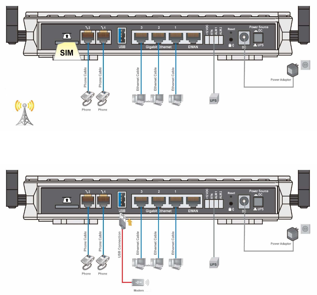
Mobile router mode
BIPAC 6300VNOZ is embedded with a module supporting mobile SIM card. It can be used to connect to high
speed mobile broadband connection.
BiPAC 6300VNOZ also supports one USB ports for your mobile dongle. It can be used to connect to high speed
mobile broadband connection, too.
7
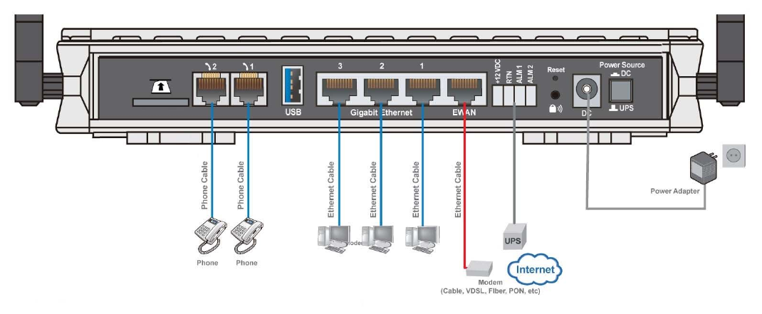
Broadband router mode
BIPAC 6300VNOZ has a Gigabits Ethernet WAN port to connect to your Fibre/ Cable/ xDSL modem.

7
Chapter 2
Installing the BIPAC 6300VNOZ
2.1 Important note for using the BIPAC 6300VNOZ
Place the BIPAC 6300VNOZ on a stable surface.
Only use the power adapter that comes with the package. Using a
different voltage rating power adaptor may damage the router.
Attention
Do not use the BIPAC 6300VNOZ in high humidity or high
temperatures.
Do not use the same power source for the BIPAC 6300VNOZ as
other equipment.
Do not open or repair the case yourself. If the BIPAC 6300VNOZ is
too hot, turn off the power immediately and have it repaired at a
qualified service center.
Avoid using this product and all accessories outdoors.
Warning
8
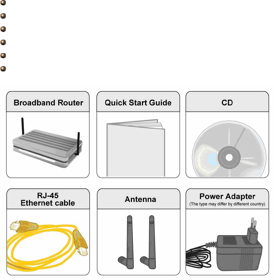
2.2 Package Contents
BIPAC 6300VNOZ - VoIP Wireless-N VPN Broadband Router
Quick Start Guide
CD containing user manual
Ethernet (RJ-45 CAT-5) cable
Two detachable Antennas
Power adapter

9
2.3 The Front LEDs
LED Status Meaning
Green System ready
1 Power
Red Boot failed
Green AC working and battery OK
Orange Only AC working, battery fail and has to change battery
Orange blinking AC fail and battery working
2 Battery
Off The power input is from power adapter not UPS
Green Transmission speed hitting 1000Mbps
Orange Transmission speed hitting 10/100Mbps
3 EWAN
Blinking Data being transmitted/received
Green Transmission speed hitting 1000Mbps
Orange Transmission speed hitting 10/100Mbps
4 Ethernet (1-3)
Blinking Data being transmitted/ received
5 USB Green Connected to a storage device
Green Wireless connection established
Green blinking Sending/ Receiving data
6 Wireless/ WPS
Orange WPS on
Green Successfully registered
7 Phone (1-2)
Orange Phone being in use
8 Signal Strength Green Signal strength > 75%

10
Green blinking quickly Signal strength 75% ~ 50%
Orange blinking quickly Signal strength 50% ~ 25%
Orange blinking slowly Signal strength < 25%
Orange No signal, but module OK
Off module fails or No module
Red Obtaining IP failure
Green Having obtained an IP address successfully
9 Internet
Off Router in bridged mode or WAN connection not present.
11
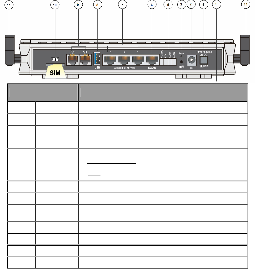
2.4 The Rear Ports
Port Meaning
1 Power Source
Power source selector. Switch between DC power adapter and UPS (DC).
2 DC Connect the supplied DC power adapter to this jack.
3 RESET After the device is powered on, press it 6 seconds or above: to restore to factory
default settings (this is used when you can not login to the router, e.g. forgot the
password)
4 Wireless On/Off
WPS
By controlling the pressing time, users can achieve two different effects:
(1) Wireless ON/OFF button: Press over 6 seconds to switch on wireless function when
wireless is off and press over 6 seconds again to disable wireless function.
(2) WPS: Press less than 6 seconds to trigger WPS function.
5 UPS Connect the supplied standardized UPS(DC) to this jack
6 EWAN Connect to Fiber/ Cable/ xDSL Modem with your RJ-45 cable.
7 Gigabit Ethernet
Connect a UTP Ethernet cable (Cat-5 or Cat-5e) to one of the three LAN ports when
connecting to a PC or an office/home network of 10Mbps /100Mbps /1000Mbps.
8 USB Connect the storage device to this port.
9 Phone (1-2) Connect your analog phone set to this port with the RJ-11 cable.
10 SIM Card slot Plug the proper mini SIM card(2FF) into the slot
11 Antenna Connect to the supplied two high performance external antennas
12
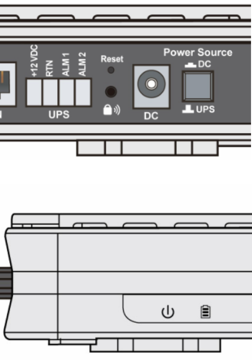
2.5 Power Source
6300VNOZ offers two kinds of power input, namely, DC power Adapter and DC UPS (or BBU).
6300VNOZ can take the advantage of UPS (Uninterruptible Power Supply) to keep working even if the power
outage hit your router when the router in working in DC UPS mode.
(a picture of the rear focusing on the power source)
(a shot from the front panel, with second icon being identified as the Battery LED)
How to switch between the two power input:
Press down "Power Source" push button, the power source is "DC" power adapter.
Press up "Power Source" push button, the power source is UPS. Device can continue to operate for a period of
time after AC power failure, due to uninterrupted power system features of UPS.(Note: a standardized DC UPS
will come to your by BEC, customers should not turn to other substandard DC UPS.)
UPS feature:
A battery LED is shown on your device front panel to indicate the DC UPS use. The battery LED is on only when
DC UPS is in use, and when the device is operating using DC power adapter, the LED unlit.
13
The meanings of the different status of Battery LED:
Green lit: AC is working, UPS battery working well
Orange Lit: Only AC is working, but Battery fails. And you have to change battery
Orange Blinking: AC fails, but battery is working
14
2.6 Cabling
One of the most common causes of problems is bad cabling. Make sure that all connected devices are turned
on. On the front panel of the product is a bank of LEDs. Verify that the LAN Link and LEDs are lit. If they are not,
verify that you are using the proper cables.
Make sure that all other devices (e.g. telephones, fax machines, analogue modems) connected to the same
telephone line as your Billion router have a line filter connected between them and the wall socket (unless you
are using a Central Splitter or Central Filter installed by a qualified and licensed electrician), and that all line
filters are correctly installed in a right way. If the line filter is not correctly installed and connected, it may cause
problems to your connection or may result in frequent disconnections.

15
Chapter 3
Basic Installation
The router can be configured with your web browser. A web browser is included as a standard application in the
following operating systems: Windows 98/NT/2000/XP/Vista/Win7, Linux, Mac OS, etc. The product provides
an easy and user-friendly interface for configuration.
3.1 Before Configuration
PCs must have an Ethernet interface installed properly and be connected to the router either directly or through
an external repeater hub, and have TCP/IP installed and configured to obtain an IP address through a DHCP
server or a fixed IP address that must be in the same subnet as the router. The default IP address of the router
is 192.168.1.254 and the subnet mask is 255.255.255.0 (i.e. any attached PC must be in the same subnet, and
have an IP address in the range of 192.168.1.1 to 192.168.1.253). The best and easiest way is to configure the
PC to get an IP address automatically from the router using DHCP. If you encounter any problems accessing the
router’s web interface it may also be advisable to uninstall any kind of software firewall on your PCs, as they
can cause problems accessing the 192.168.1.254 IP address of the router. Users should make their own
decisions on how to best protect their network.
Please follow the steps below for your PC’s network environment installation. First of all, please check your PC’s
network components. The TCP/IP protocol stack and Ethernet network adapter must be installed. If not, please
refer to your Windows-related or other operating system manuals.
Any TCP/IP capable workstation can be used to communicate with or
through the BIPAC 6300VNOZ. To configure other types of workstations,
please consult the manufacturer’s documentation.
16
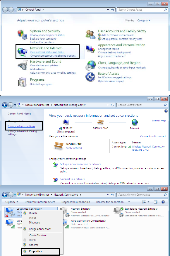
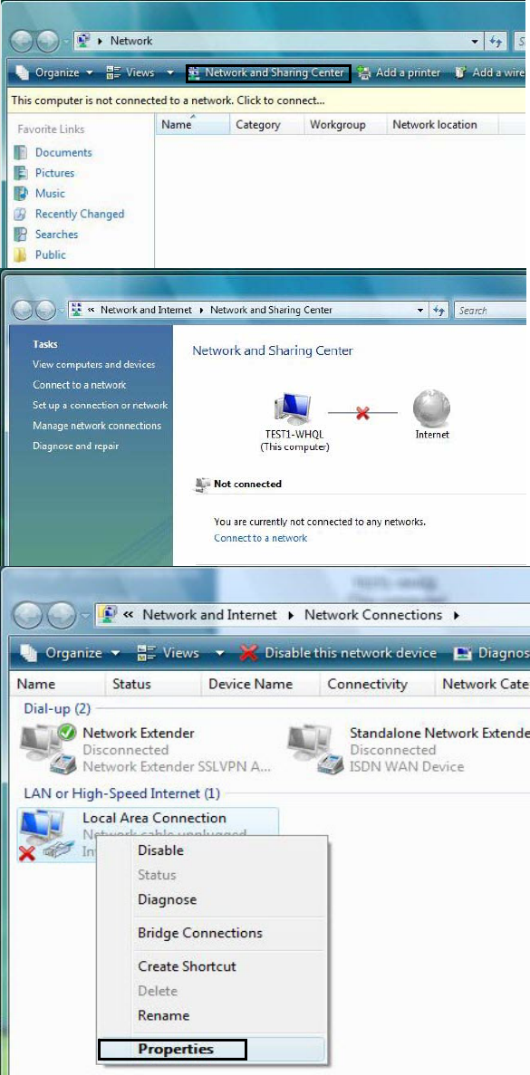
3.1.1 Configuring a PC in Windows 7
1. Go to Start. Click on Control
Panel. Then click on Network
and Internet.
2. When the Network and
Sharing Center window pops
up, select and click on Change
adapter settings on the left
window panel.
3. Select the Local Area
Connection, and right click the
icon to select Properties.
17
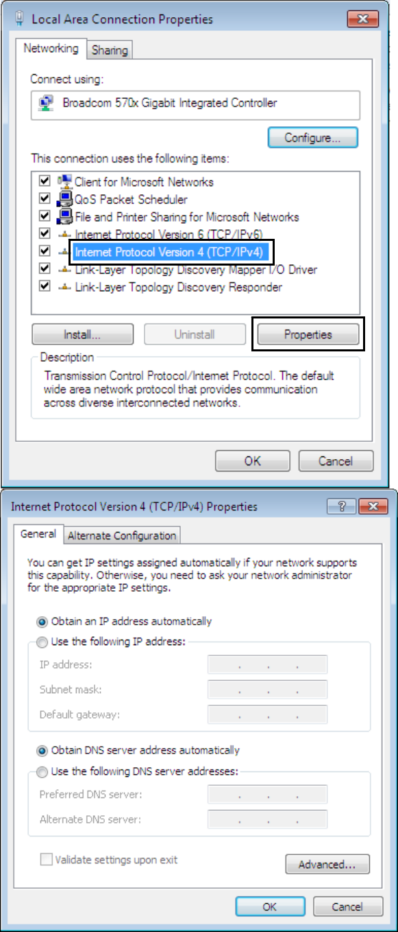
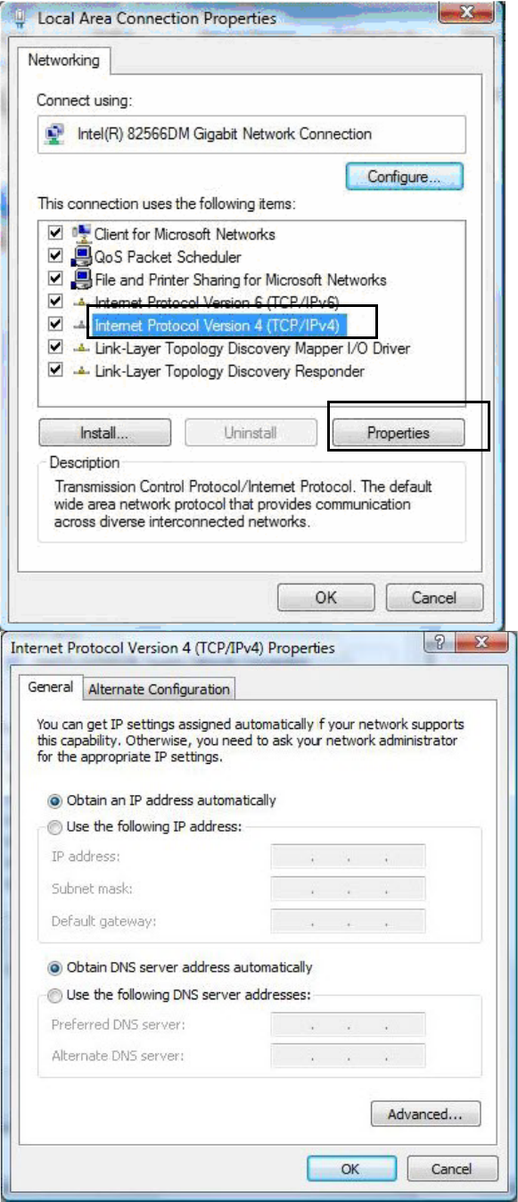
IPv4:
4. Select Internet Protocol
Version 4 (TCP/IPv4) then
click Properties
5. In the TCP/IPv4 properties
window, select the Obtain an IP
address automatically and
Obtain DNS Server address
automatically radio buttons.
Then click OK to exit the
setting.
6. Click OK again in the Local
Area Connection Properties
window to apply the new
configuration.
18
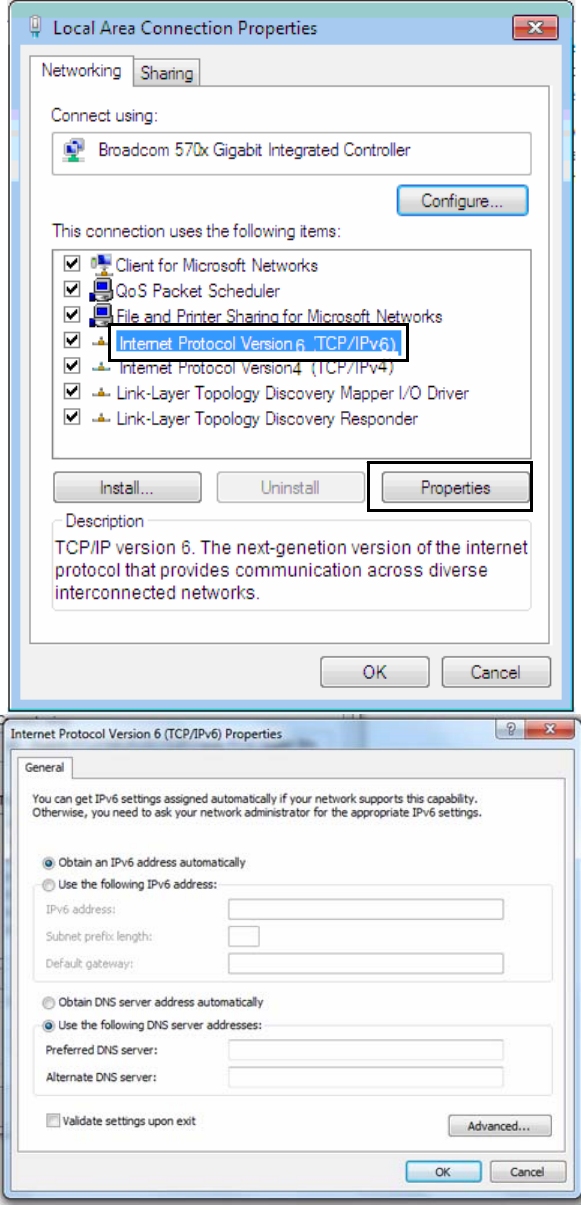
IPv6:
4. Select Internet Protocol
Version 6 (TCP/IPv6) then
click Properties
5. In the TCP/IPv6 properties
window, select the Obtain an
IPv6 address automatically
and Obtain DNS Server
address automatically radio
buttons. Then click OK to exit
the setting.
6. Click OK again in the Local
Area Connection Properties
window to apply the new
configuration.
19
3.1.2 Configuring a PC in Windows Vista
1. Go to Start. Click on Network.
Then click on Network and
Sharing Center at the top bar.
2. When the Network and
Sharing Center window pops
up, select and click on Manage
network connections on the
left window pane.
3. Select the Local Area
Connection, and right click the
icon to select Properties.
20
IPv4:
4. Select Internet Protocol
Version 4 (TCP/IPv4) then click
Properties.
5. In the TCP/IPv4 properties
window, select the Obtain an IP
address automatically and
Obtain DNS Server address
automatically radio buttons.
Then click OK to exit the setting.
6. Click OK again in the Local
Area Connection Properties
window to apply the new
configuration.
21
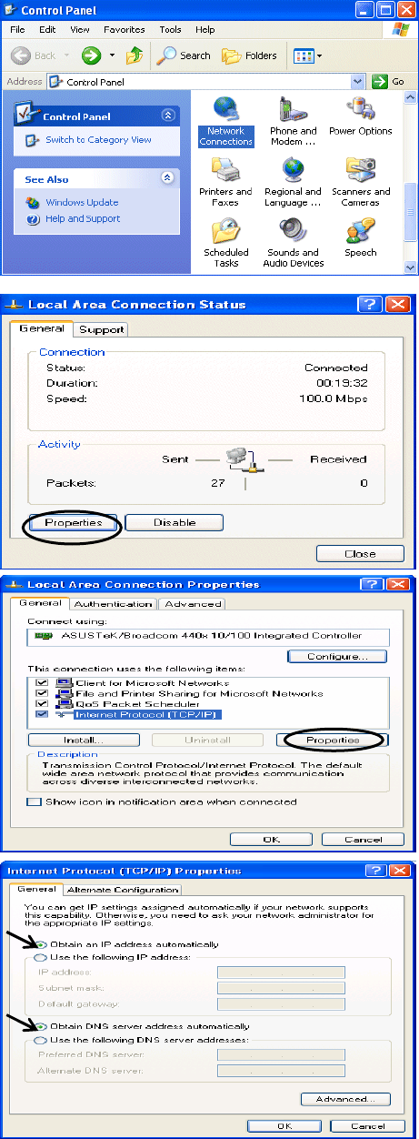
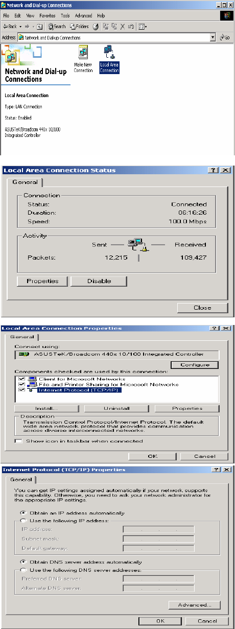
3.1.3 Configuring a PC in Windows XP
IPv4:
1. Go to Start / Control Panel (in Classic
View). In the Control Panel, double-click on
Network Connections
2. Double-click Local Area Connection.
3. In the Local Area Connection Status
window, click Properties.
4. Select Internet Protocol (TCP/IP) and click
Properties.
5. Select the Obtain an IP address
automatically and the Obtain DNS server
address automatically radio buttons.
6. Click OK to finish the configuration.
22
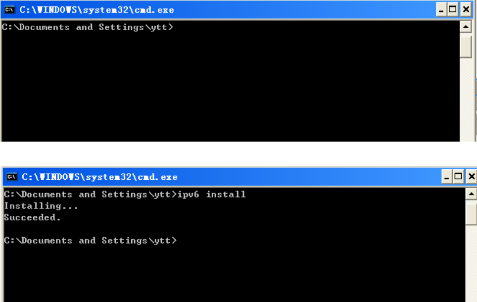
IPv6:
IPv6 is supported by Windows XP, but you should install it first.
Act as shown below:
1. On the desktop, Click Start > Run, type cmd, then press Enter key in the keyboard, the following screen
appears.
2. Key in command ipv6 install
Configuration is OK now, you can test whether it works ok.
23
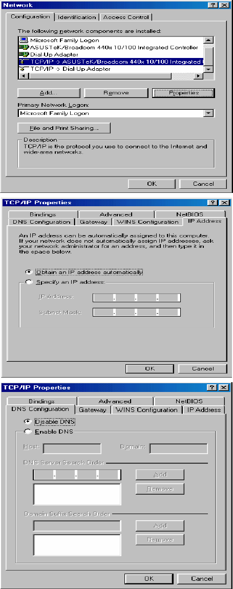
3.1.4 Configuring a PC in Windows 2000
1. Go to Start / Settings / Control Panel. In
the Control Panel, double-click on Network
and Dial-up Connections.
2. Double-click Local Area Connection.
3. In the Local Area Connection Status
window click Properties.
4. Select Internet Protocol (TCP/IP) and click
Properties.
5. Select the Obtain an IP address
automatically and the Obtain DNS server
address automatically radio buttons.
6. Click OK to finish the configuration.
24
3.1.5 Configuring a PC in Windows 98/Me
1. Go to Start / Settings / Control Panel. In
the Control Panel, double-click on Network
and choose the Configuration tab.
2. Select TCP/IP ->NE2000 Compatible, or
the name of your Network Interface Card
(NIC) in your PC.
3. Select the Obtain an IP address
automatically radio button.
4. Then select the DNS Configuration tab.
5. Select the Disable DNS radio button and
click OK to finish the configuration.
25
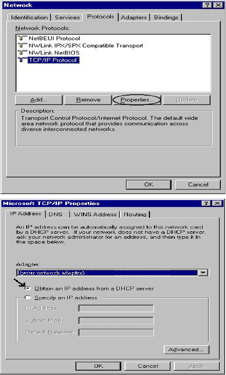
3.1.6 Configuring a PC in Windows NT4.0
1. Go to Start / Settings / Control Panel. In
the Control Panel, double-click on
Network and choose the Protocols tab.
2. Select TCP/IP Protocol and click
Properties.
3. Select the Obtain an IP address from a
DHCP server radio button and click OK.

26
3.2 Factory Default Settings
Before configuring your router, you need to know the following default settings.
Web Interface:
Username: admin
Password: admin
LAN Device IP Settings:
IP Address: 192.168.1.254
Subnet Mask: 255.255.255.0
DHCP server:
DHCP server is enabled.
Start IP Address: 192.168.1.100
IP pool counts: 20
3.2.1 Username and Password
The default username and password are “admin” and “admin” respectively.
Attention
Attention
If you ever forget the password to log in, you may press the RESET button
up to 6 seconds to restore the factory default settings.

27
3.3 LAN Port Addresses
The parameters of LAN ports are pre-set in the factory. The default values are shown below.
IPv4:
IP address 192.168.1.254
Subnet Mask 255.255.255.0
DHCP server function Enabled
IP addresses for distribution to PCs 100 IP addresses continuing from 192.168.1.100 through
192.168.1.199
3.4 Information from your ISP
Before configuring this device, you have to check with your ISP (Internet Service Provider) what kind of service
is provided such as EWAN ((Dynamic IP address, Static IP address, PPPoE, Bridge Mode).
Gather the information as illustrated in the following table and keep it for reference.
EWAN:
PPPoE Username, Password, Service Name, and Domain Name System (DNS) IP
address (it can be automatically assigned by your ISP when you connect or be
set manually).
Dynamic IP Address Domain Name System (DNS) IP address (it can be automatically assigned by
your ISP when you connect or be set manually).
Static IP Address Static IP Address, IP Subnet Mask, Gateway IP Address, and Domain Name
System (DNS) IP address.
Bridge Mode Pure bridge.
28
Chapter 4
Configuration
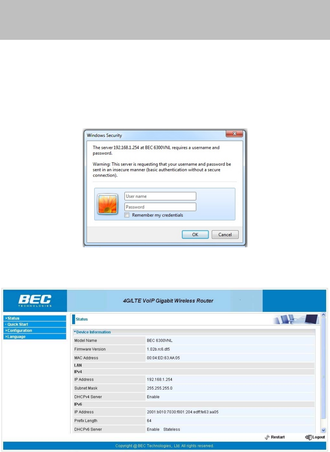
4.1 Configuring BIPAC 6300VNOZ with your Web Browser
Open your web browser, enter the IP address of your router, which by default is 192.168.1.254, and click “OK”,
a user name and password window prompt will appear. The default username and password are “admin” and
“admin”.
Congratulation! You are now successfully logged on to the BIPAC 6300VNOZ!

29
At the configuration homepage, the left navigation pane where bookmarks are provided links you directly to the
desired setup page, including:
Status(Device Info, System Log, Statistics, DHCP Table, Disk Status, VoIP Status)
Quick Start (Wizard Setup)
Configuration (Interface Setup, Advanced Setup, VoIP, Access Management, Maintenance)
Language
Please see the relevant sections of this manual for detailed instructions on how to configure your router.
30
4.2 Status
In this section, you can check the router working status, including Device Info, System Log, Statistics, DHCP
Table, Disk Status, and VoIP Status.
31
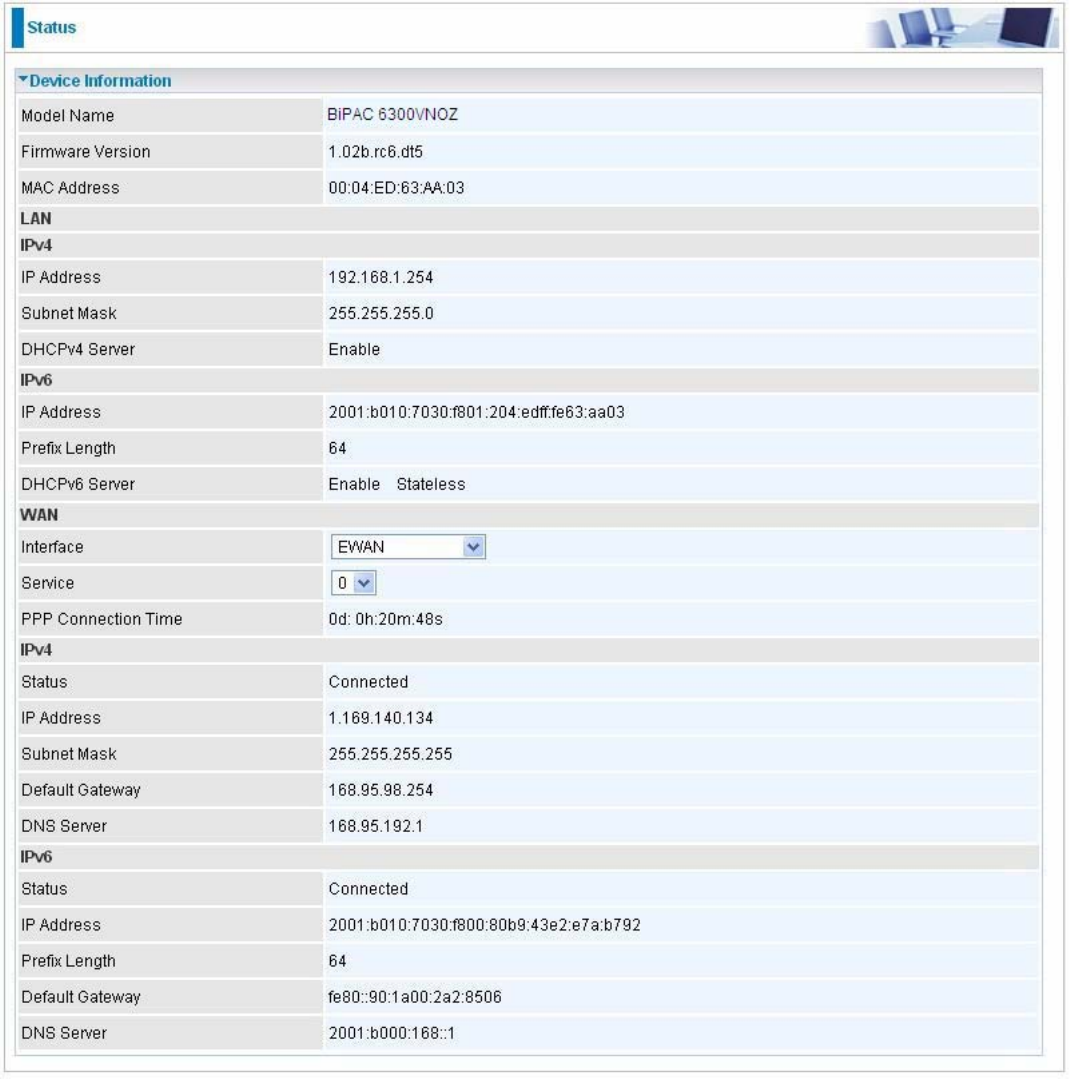
4.2.1 Device Info
Users will see device's basic information in this page.
EWAN

32
Device Information
Model Name: Show model name of the router
Firmware Version: This is the Firmware version
MAC Address: This is the MAC Address
LAN
IPv4:
IP Address: LAN port IPv4 address.
Subnet Mask: LAN port IP subnet mask.
DHCPv4 Server: LAN port DHCP role - Enabled, Relay or Disabled.
IPv6:
IP Address: LAN port IPv6 address.
Prefix Length: The prefix length
DHCPv6 Server: The DHCP status.
WAN
Interface: The now used connection method, "EWAN".
Service: The WAN interface service index.
PPP Connection Time: The time totaled since PPP has been successfully connected.
IPv4:
Status: The connection status, Not connected or Connected.
IP Address: WAN port IP address.
Subnet Mask: WAN port IP subnet mask.
Default Gateway: The IP address of the default gateway.
DNS Server: DNS information.
IPv6:
Status: The IPv6 connection status.
IP Address: WAN port IPv6 address.
Prefix Length: The prefix length of IPv6 address.
Default Gateway: The IP address of the default gateway.
DNS Server: DNS information.
33
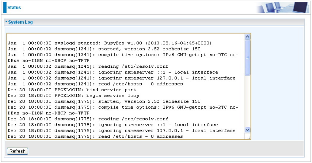
4.2.2 System Log
In system log, users can check the operations to the router and track the glitches to the router when occurred.
Refresh: Press this button to refresh the statistics.
34
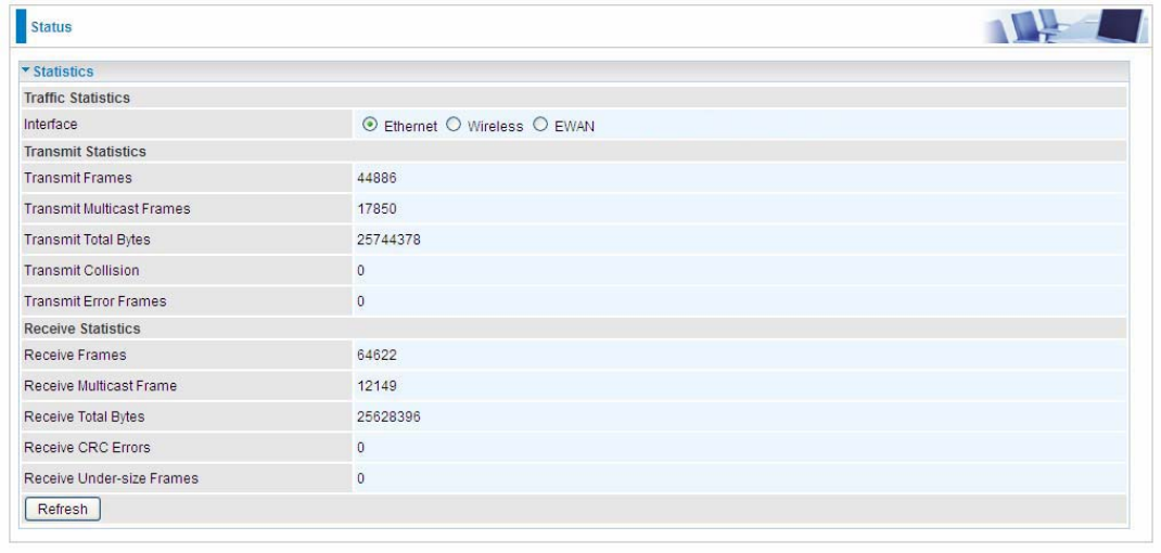
4.2.3 Statistics
Ethernet
Interface: This field displays the type of port
Transmit Frames: This field displays the number of frames transmitted until the latest second.
Transmit Multicast Frames: This field displays the number of multicast frames transmitted until the latest
second.
Transmit Total Bytes: This field displays the number of bytes transmitted until the latest second.
Transmit Collision: This is the number of collisions on this port.
Transmit Error Frames: This field displays the number of error packets on this port.
Receive Frames: This field displays the number of frames received until the latest second.
Receive Multicast Frames: This field displays the number of multicast frames received until the latest second.
Receive Total Bytes: This field displays the number of bytes received until the latest second.
Receive CRC Errors: This field displays the number of error packets on this port.
Receive Under-size Frames: This field displays the number of under-size frames received until the latest
second.
Refresh: Press this button to refresh the statistics.
35
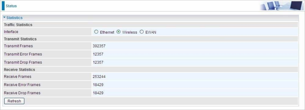
Wireless
Transmit Frames: This field displays the number of frames transmitted until the latest second.
Transmit Error Frames: This field displays the number of error frames transmitted until the latest second.
Transmit Drop Frames: This field displays the number of drop frames transmitted until the latest second.
Receive Frames: This field displays the number of frames received until the latest second.
Receive Error Frames: This field displays the number of error frames received until the latest second.
Receive Drop Frames: This field displays the number of drop frames received until the latest second.
Refresh: Press this button to refresh the statistics.
36
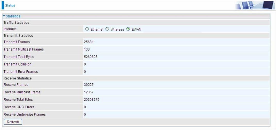
EWAN
Transmit Frames: This field displays the total number of frames transmitted until the latest second.
Transmit Multicast Frames: This field displays the total number of multicast frames transmitted till the latest
second.
Transmit Total Bytes: This field displays the total number of bytes transmitted until the latest second.
Transmit Collision: This is the number of collisions on this port.
Transmit Error Frames: This field displays the number of error packets on this port.
Receive Frames: This field displays the number of frames received until the latest second.
Receive Multicast Frames: This field displays the number of multicast frames received until the latest second.
Receive Total Bytes: This field displays the number of bytes received until the latest second.
Receive CRC Errors: This field displays the number of error packets on this port.
Receive Under-size Frames: This field displays the number of under-size frames received until the latest
second.
Refresh: Press this button to refresh the statistics.
37
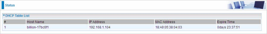
4.2.4 DHCP Table
DHCP table displays the devices connected to the router with clear information.
#: The index identifying the connected devices.
Host Name: Show the hostname of the PC.
IP Address: The IP allocated to the device.
MAC Address: The MAC of the connected device.
Expire Time: The total remaining interval since the IP assignment to the PC.
38
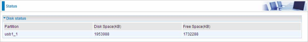
4.2.5 Disk Status
Partition: Display the USB storage partition.
Disk Space(KB): Display the total storage space of the NAS in KBytes unit.
Free Space(KB): Display the available space in KBytes unit.
39
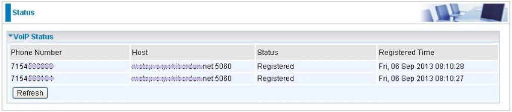
4.2.6 VoIP Status
4.2.6.1 VoIP Status
VoIP status give users a directive picture on the registered VoIP accounts.
Phone Number: The phone number user registers and fills in the Basic page of VoIP.
Host: Show the IP address and port number of SIP Registrar.
Status: The status of the registered SIP account.
Registered Time: The duration the account has been successfully registered to the SIP registrar.
40
4.3 Quick Start
For detailed instructions on configuring WAN settings, see the Interface Setup section of this manual.
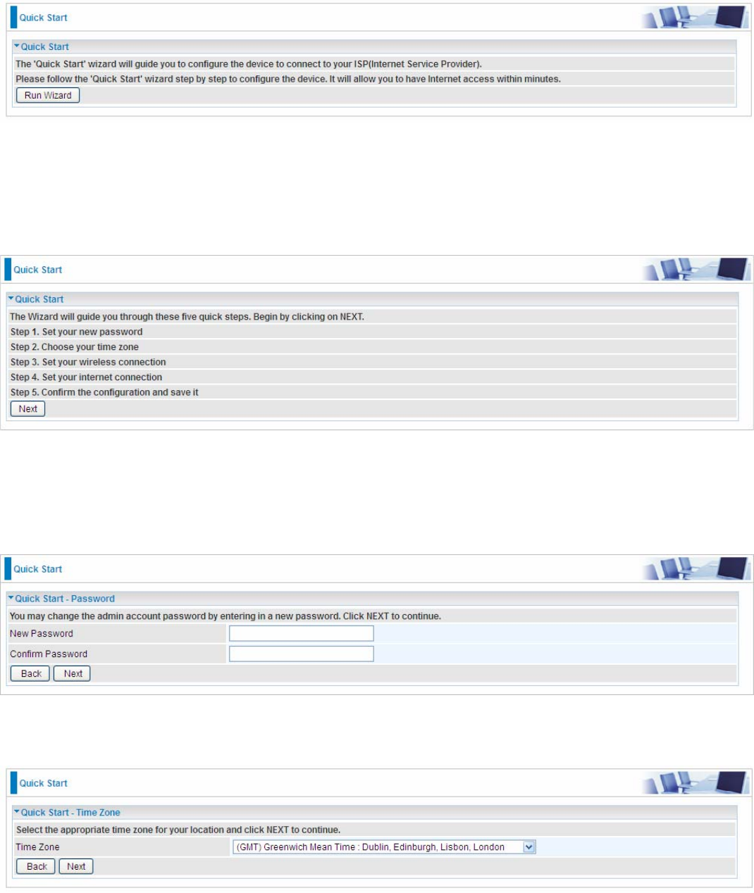
The Quick Start Wizard is a useful and easy utility to help setup the device to quickly connect to your ISP
(Internet Service Provider) with only a few steps required. It will guide you step by step to configure the
password, time zone, and WAN settings of your device. The Quick Start Wizard is a helpful guide for first time
users to the device.
Click NEXT to enter step 1.
Step1. Set new password of the “admin” account. The password was used to manage the web access. The
default is “admin”. Once changed, please remember carefully. Click NEXT to continue.
Step2: Choose your time zone. Click NEXT to continue.
41
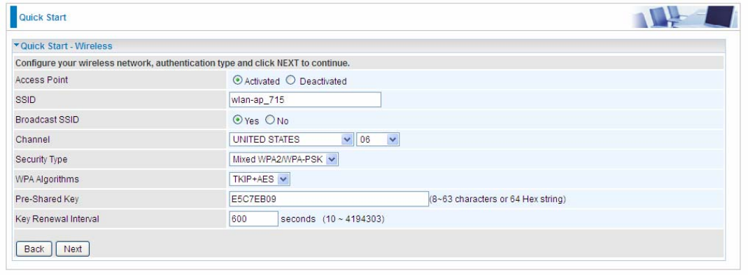
Step3: Set your wireless connection. Click NEXT to continue.
42
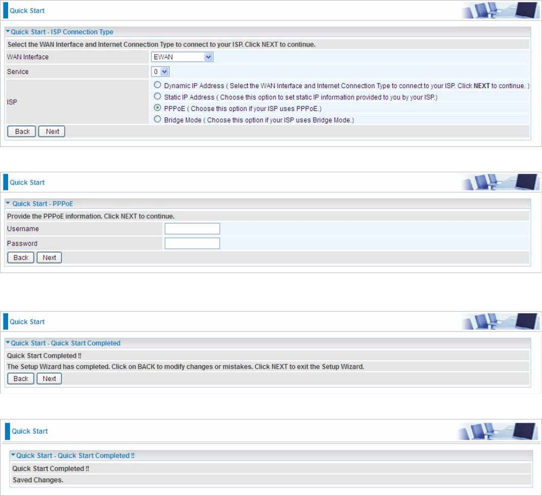
Step4: Set your Internet connection
WAN Transfer Modes: EWAN
EWAN
1). Select EWAN. Refer to your ISP to choose the appropriate connection protocol. Click NEXT to continue.
2). Enter the PPPoE account information provided to you by your ISP. Click NEXT to continue.
3).The Setup Wizard has completed. Click on BACK to modify changes or mistakes. Click NEXT to save the
current settings.
4). Quick Start Completed!

43
Switch to Status > Device Info to view the status.
44
4.4 Configuration
Click this item to access the following sub-items that configure the router: Interface Setup, Advanced Setup,
VoIP, Access Management, and Maintenance.
45
4.4.1 Interface Setup
First, let us take a look at the Interface Setup. There are four items contained in this section, namely, Internet,
LAN, Wireless and Wireless MAC Filter. Each is described in the following scenario.
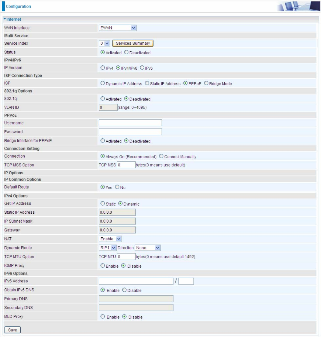
4.4.1.1 Internet
EWAN
46
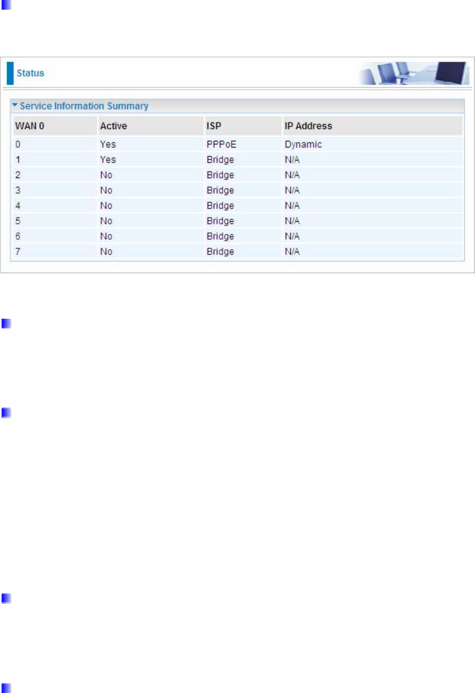
Multi Service
Service Index: The index to mark the EWAN interface of different ISP type, ranging from 0-7.
Service Summary: The diagram for view of service information.
Status: Select whether to enable the service.
IPv4/IPv6
IP version: choose IPv4, IPv4/IPv6, IPv6 based on users’ environment.
Here we take IPv4/IPv6 for example, when you just choose IPv4 or IPv6, you can just get information from the
following listed parameters.
ISP Connection Type:
ISP: Select the encapsulation type your ISP uses.
Dynamic IP: Select this option if your ISP provides you an IP address automatically. This option is
typically used for Cable services. Please enter the Dynamic IP information accordingly.
Static IP: Select this option to set static IP information. You will need to enter in the Connection type, IP
address, subnet mask, and gateway address, provided to you by your ISP. Each IP address entered in
the fields must be in the appropriate IP form, which is four IP octets separated by a dot (xx.xx.xx.xx). The
Router will not accept the IP address if it is not in this format.
PPPoE: Select this option if your ISP requires you to use a PPPoE connection.
Bridge: Select this mode if you want to use this device as an OSI layer 2 device like switch.
802.1q Options
802.1q: Select whether to activate 802.1q feature. When activated, please enter the the VLAN ID.
VLAN ID: It is a parameter to specify the VLAN which the frame belongs. Enter the VLAN ID identification,
tagged: 0-4095.
PPPoE
Username: Enter the user name exactly as your ISP assigned.
Password: Enter the password associated with the user name above.
Bridge Interface for PPPoE: When “Activated”, the device will gain WAN IP from your ISP with the PPPoE
account. But if your PC is connected to the router working as a DHCP client, in this mode, the device acts as a
NAT router; while if you dial up with the account within your PC, the device will then work as a bridge forwarding
the PPPoE information to the PPPoE server and send the response to your PC, thus your PC gets a WAN IP

47
working in the internet.
Connection Setting
Connection:
Always On: Click on Always On to establish a PPPoE session during start up and to automatically
re-establish the PPPoE session when disconnected by the ISP.
Connect Manually: Select Connect Manually when you don't want the connection up all the time.
TCP MSS Option: Enter the TCP Maximum Segment Size (MSS).
IP Options
Default Route: Select Yes to use this interface as default route interface.
IPv4 options:
Get IP Address: Choose Static or Dynamic
Static IP Address: If Static is selected in the above field, please enter the specific IP address you get from ISP
and the following IP subnet mask and gateway address.
IP Subnet Mask: The default is 0.0.0.0. User can change it to other such as 255.255.255.0.Type the subnet
mask assigned to you by your ISP (if given).
Gateway: Enter the specific gateway IP address you get from ISP.
NAT: Select Enable if you use this router to hold a group of PCs to get access to the internet.
Dynamic Route:
RIP Version: (Routing Information protocol) Select this option to specify the RIP version, including RIP-1,
RIP-2.
RIP Direction: Select this option to specify the RIP direction.
None is for disabling the RIP function.
Both means the router will periodically send routing information and accept routing information then
incorporate into routing table.
IN only means the router will only accept but will not send RIP packet.
OUT only means the router will only send but will not accept RIP packet.
TCP MTU Option: Maximum Transmission Unit, the maximum is 1500.
IGMP Proxy: IGMP (Internet Group Multicast Protocol) is a network-layer protocol used to establish
membership in a Multicast group. Choose whether enable IGMP proxy.
IPv6 options (only when choose IPv4/IPv6 or just IPv6 in IP version field above):
IPv6 Address: Type the WAN IPv6 address from your ISP.
Obtain IPv6 DNS: Choose if you want to obtain DNS automatically.
Primary/Secondary: if you choose Disable in the Obtain IPv6 DNS field, please type the exactly primary and
secondary DNS.
MLD Proxy: MLD (Multicast Listener Discovery Protocol) is to IPv6 just as IGMP to IPv4. It is a Multicast
Management protocol for IPv6 multicast packets.

48
When router’s Internet configuration is finished successfully, you can go to status to get the connection
information.
49
4.4.1.2 LAN
A Local Area Network (LAN) is a shared communication system to which many computers are attached and is
limited to the immediate area, usually the same building or floor of a building.
IPv6
The IPv6 address composes of two parts, thus, the prefix and the interface ID.
There are two ways to dynamically configure IPv6 address on hosts. One is statefull configuration, for example
using DHCPv6 (which resembles its counterpart DHCP in IPv4.) In the stateful autoconfiguration model, hosts
obtain interface addresses and/or configuration information and parameters from a DHCPv6 server. The Server
maintains a database that keeps track of which addresses have been assigned to which hosts.
The second way is stateless configuration. Stateless auto-configuration requires no manual configuration of
hosts, minimal (if any) configuration of routers, and no additional servers. The stateless mechanism allows a
host to generate its own addresses using a combination of locally available information (MAC address) and
information (prefix) advertised by routers. Routers advertise prefixes that identify the subnet(s) associated with
a link, while hosts generate an "interface identifier" that uniquely identifies an interface on a subnet. An address
is formed by combining the two. When using stateless configuration, you needn’t configure anything on the
client.
50
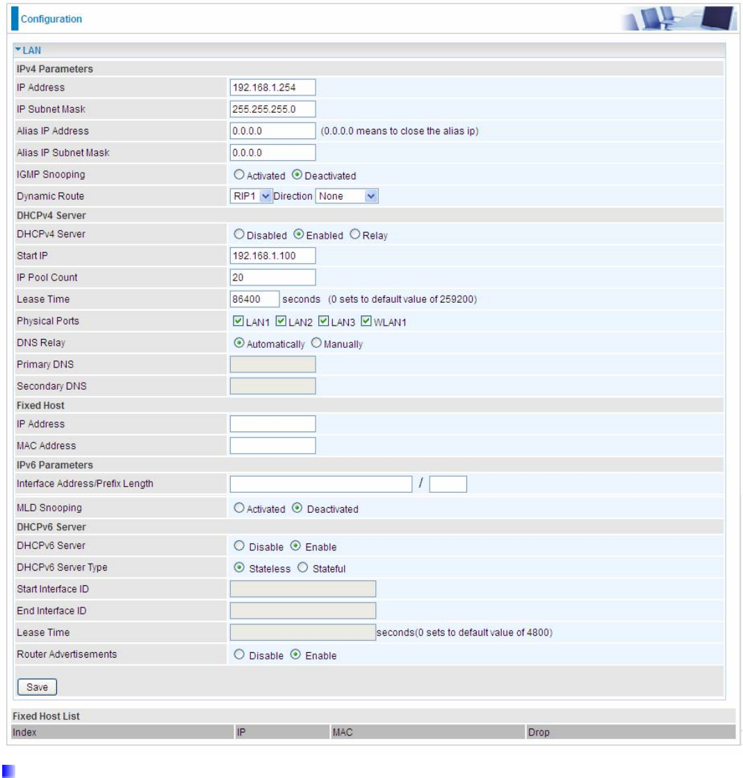
IPv4 Parameters
IP Address: Enter the IP address of Router in dotted decimal notation, for example, 192.168.1.254 (factory
default).
IP Subnet Mask: The default is 255.255.255.0. User can change it to other such as 255.255.255.128.
Alias IP Address: This is for local networks virtual IP interface. Specify an IP address on this virtual interface.
Alias IP Subnet Mask: Specify a subnet mask on this virtual interface.
IGMP Snooping: Select Activated to enable IGMP Snooping function, Without IGMP snooping, multicast
traffic is treated in the same manner as broadcast traffic - that is, it is forwarded to all ports. With IGMP snooping,
multicast traffic of a group is only forwarded to ports that have members of that group.
Dynamic Route: Select the RIP version from RIP1 or RIP2.
51
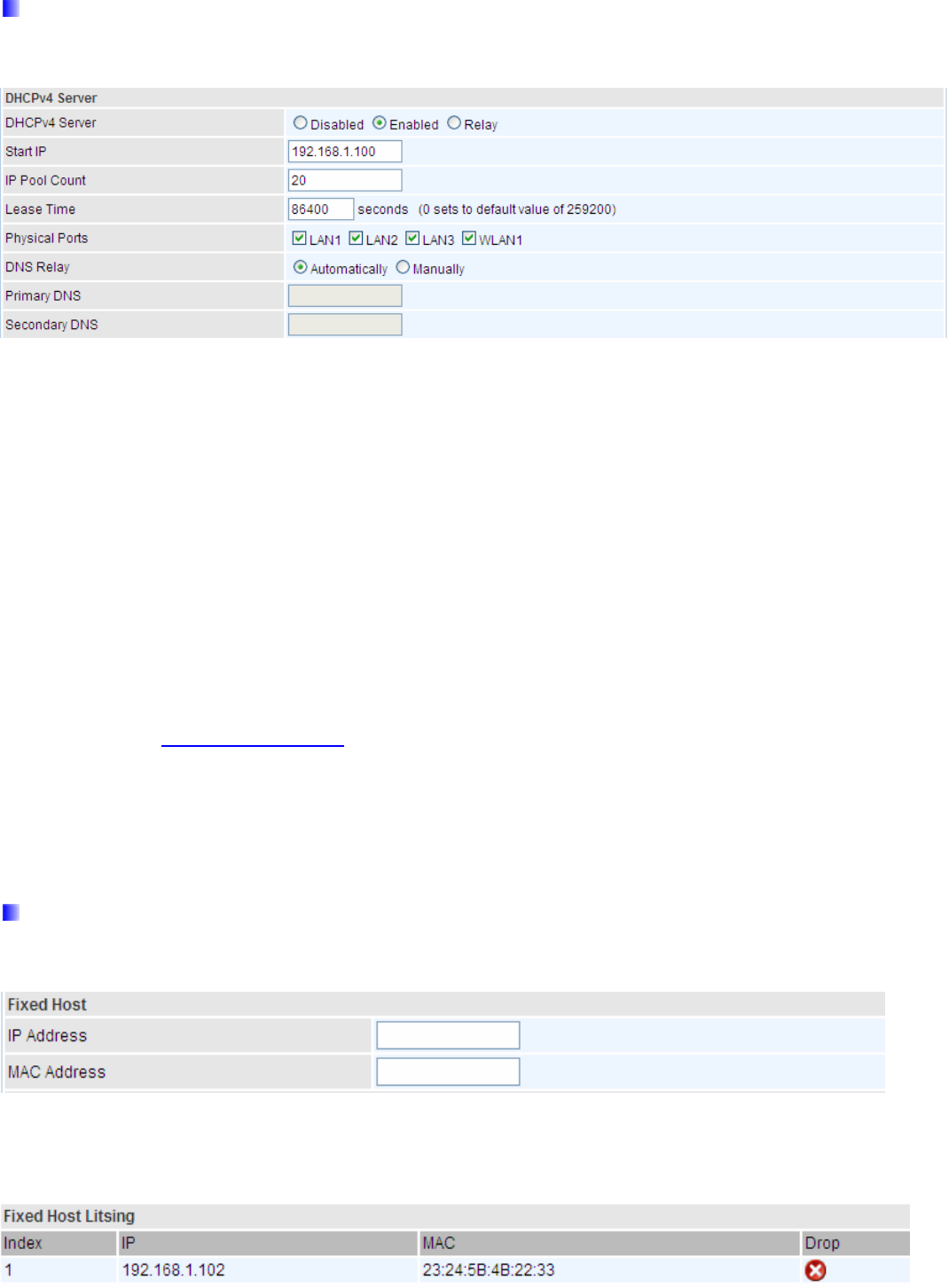
DHCPv4 Server
DHCP (Dynamic Host Configuration Protocol) allows individual clients to obtain TCP/IP configuration at start-up
from a server.
DHCPv4 Server: If set to Enabled, your BIPAC 6300VNOZ can assign IP addresses, default gateway and DNS
servers to the DHCP client.
If set to Disabled, the DHCP server will be disabled.
If set to Relay, the BIPAC 6300VNOZ acts as a surrogate DHCP server and relays DHCP requests and
responses between the remote server and the clients. Enter the IP address of the actual, remote DHCP
server in the Remote DHCP Server field in this case.
When DHCP is used, the following items need to be set.
Start IP: This field specifies the first of the contiguous addresses in the IP address pool.
IP Pool Count: This field specifies the count of the IP address pool.
Lease Time: The current lease time of client.
Physical Ports: Select to determine if the DHCPv4 server is applicable to the specific port or ports. By default,
all ports can obtain local IP from DHCPv4 server.
DNS Relay Select Automatically obtained or Manually set (if selected. Please set the exactly information). If you
set Static IP in the ISP Connection Type field, then select Manually here and set the specific DNS information.
Primary DNS Server: Enter the IP addresses of the DNS servers. The DNS servers are passed to the DHCP
clients along with the IP address and the subnet mask.
Secondary DNS Server: Enter the IP addresses of the DNS servers. The DNS servers are passed to the
DHCP clients along with the IP address and the subnet mask.
Fixed Host
In this field, users can map the specific IP (must in the DHCP IP pool) for some specific MAC, and this
information can be listed in the following table.
IP Address: Enter the specific IP. For example: 192.168.1.110.
MAC Address: Enter the responding MAC. For example: 00:0A:F7:45:6D:ED
When added, you can see the ones listed as showed below:
52
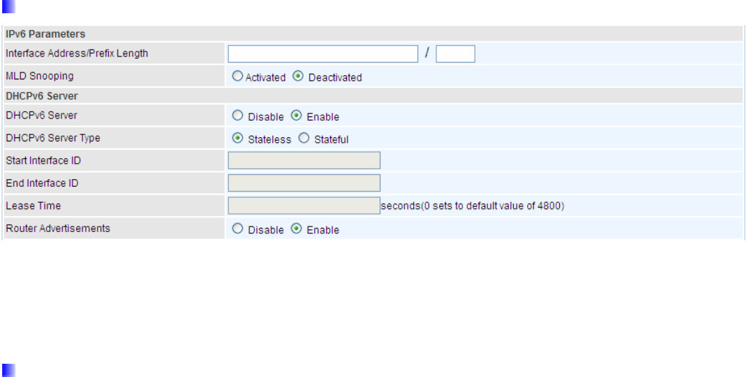
IPv6 parameters
Interface Address / Prefix Length: enter the static LAN IPv6 address, we suggest leave the field empty
because when setted wrong, it will result in LAN devices not being able to access other IPv6 device through
internet. Router will take the same WAN’s prefix to LAN side if the field is empty.
MLD Snooping: Similar to IGMP Snooping, but applicable for IPv6.
DHCPv6 Server
DHCPv6 Server: Check whether to enable DHCPv6 server.
DHCPv6 Server Type: Select Stateless or Stateful. When DHCPv6 is enabled, this parameter is available.
Stateless: If selected, the PCs in LAN are configured through RA mode, thus, the PCs in LAN are
configured through RA mode, to obtain the prefix message and generate an address using a
combination of locally available information (MAC address) and information (prefix) advertised by
routers, but they can obtain such information like DNS from DHCPv6 Server.
Stateful: If selected, the PCs in LAN will be configured like in IPv4 mode, thus obtain addresses and
DNS information from DHCPv6 server.
Start interface ID: enter the start interface ID. The IPv6 address composed of two parts, thus, the prefix and the
interface ID. Interface is like the Host ID compared to IPv4.
End interface ID: enter the end interface ID.
Leased Time (hour): the leased time, similar to leased time in DHCPv4, is a time limit assigned to clients, when
expires, the assigned ID will be recycled and reassigned.
Issue Router Advertisement: Check whether to enable issue Router Advertisement feature. It is to send
Router Advertisement messages periodically. Router will multicast the v6 Prefix information (similar to v4
network number 192.168.1.0) to all LAN devices if the field is enabled. We suggest enabling this field.
53
4.4.1.3 Wireless
This section introduces the wireless LAN and some basic configurations. Wireless LANs can be as complex as
a number of computers with wireless LAN cards communicating through access points which bridge network
traffic to the wired LAN.

54
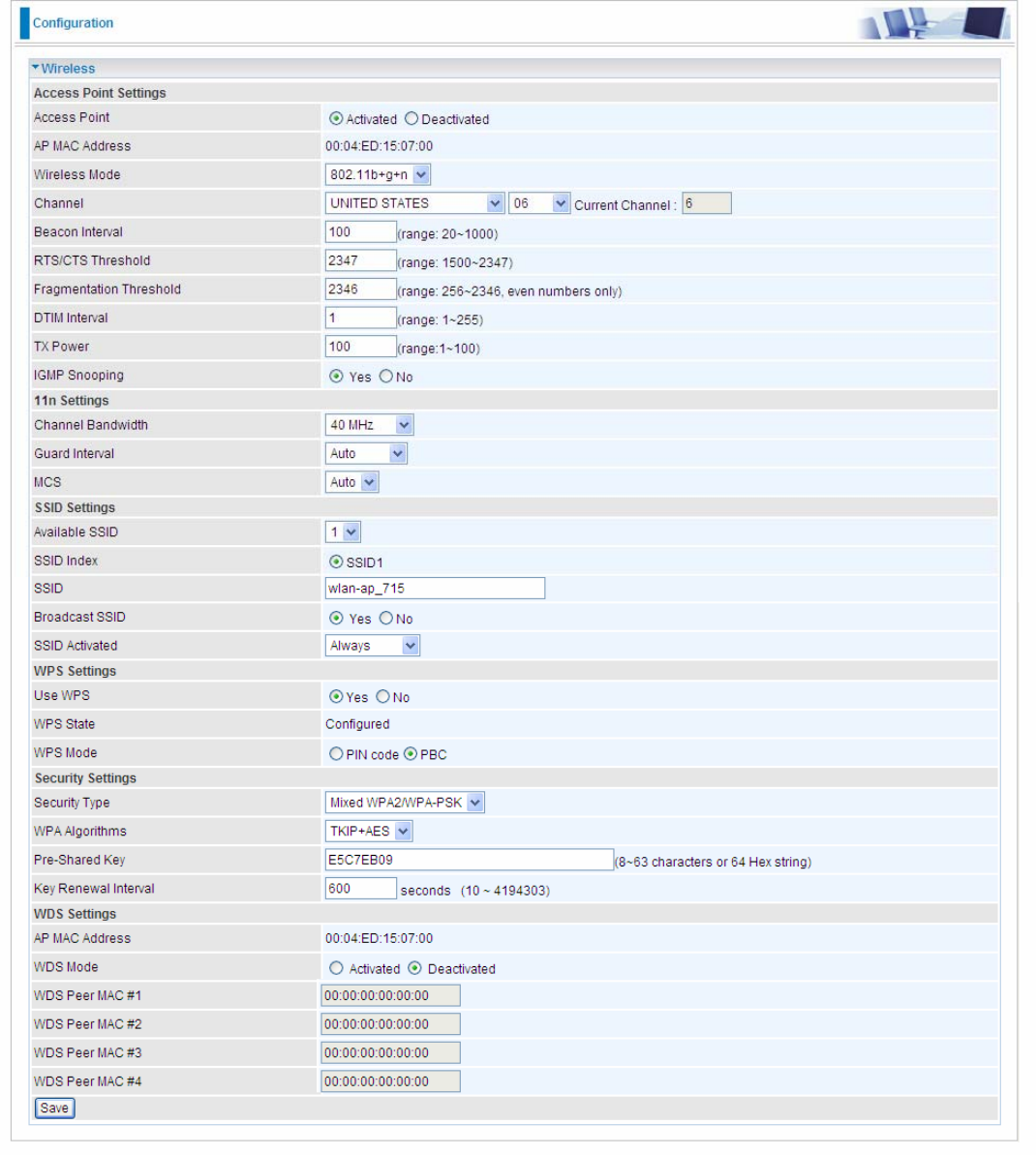
Access Point Settings
Access Point: Default setting is set to Activated. If you want to close the wireless interface, select
Deactivated.
AP MAC Address: The MAC address of wireless AP.
Wireless Mode: The default setting is 802.11b+g+n (Mixed mode). If you do not know or have both 11g and
11b devices in your network, then keep the default in mixed mode. From the drop-down manual, you can select
802.11g if you have only 11g card. If you have only 11b card, then select 802.11b and if you only have 802.11n
then select 802.11n.
Channel: The range of radio frequencies used by IEEE 802.11b/g/n wireless devices is called a channel. There
are Regulation Domains and Channel ID in this field. The Channel ID will be different based on Regulation
Domains. Select a channel from the drop-down list box.
Beacon interval: The Beacon Interval value indicates the frequency interval of the beacon. Enter a value
between 20 and 1000. A beacon is a packet broadcast by the Router to synchronize the wireless network.
RTS/CTS Threshold: The RTS (Request To Send) threshold (number of bytes) for enabling RTS/CTS
handshake. Data with its frame size larger than this value will perform the RTS/CTS handshake. Enter a value
between 1500 and 2347.
Fragmentation Threshold: The threshold (number of bytes) for the fragmentation boundary for directed
messages. It is the maximum data fragment size that can be sent. Enter a value between 256 and 2346, even
number only.
DTIM Interval: This value, between 1 and 255, indicates the interval of the Delivery Traffic Indication Message
(DTIM).
TX Power: The transmission power of the antennas, ranging from 1-100, the higher the more powerful of the
transmission performance.
IGMP Snooping: Enable or disable the IGMP Snooping function for wireless. Without IGMP snooping,
multicast traffic is treated in the same manner as broadcast traffic - that is, it is forwarded to all ports. With IGMP
snooping, multicast traffic of a group is only forwarded to ports that have members of that group.”
11n Settings
Channel Bandwidth: Select either 20 MHz or 20/40 MHz for the channel bandwidth. The wider the Channel
bandwidth the better the performance will be.
Guard Interval: Select either 400nsec or 800nsec for the guard interval. The guard interval is here to ensure
that data transmission do not interfere with each other. It also prevents propagation delays, echoing and
reflections. The shorter the Guard Interval, the better the performance will be. We recommend users to select
Auto.
MCS: There are options 0~15 and AUTO to select for the Modulation and Coding Scheme. We recommend
users selecting AUTO.
SSID Settings
Available SSID: User can determine how many virtual SSIDs to be used. Default is 1, maximum is 4.
SSID Index: Select how many SSIDs you want to lay out. A total of 4 is in list. By default 4 SSIDs are in use.
SSID: The SSID is the unique name of a wireless access point (AP) to be distinguished from another. For
security propose, change the default wlan-ap to a unique ID name to the AP which is already built-in to the
router’s wireless interface. Make sure your wireless clients have exactly the SSID as the device, in order to get
connected to your network.
Broadcast SSID: Select Yes to make the SSID visible so a station can obtain the SSID through passive
scanning. Select No to hide the SSID in so a station cannot obtain the SSID through passive scanning.
SSID Activated: Select the time period during which the SSID is active. Default is always which means the
SSID will be active all the time without time control. See 4.4.2.8 Time Schedule to set the timeslot to flexibly
control when the SSID functions.