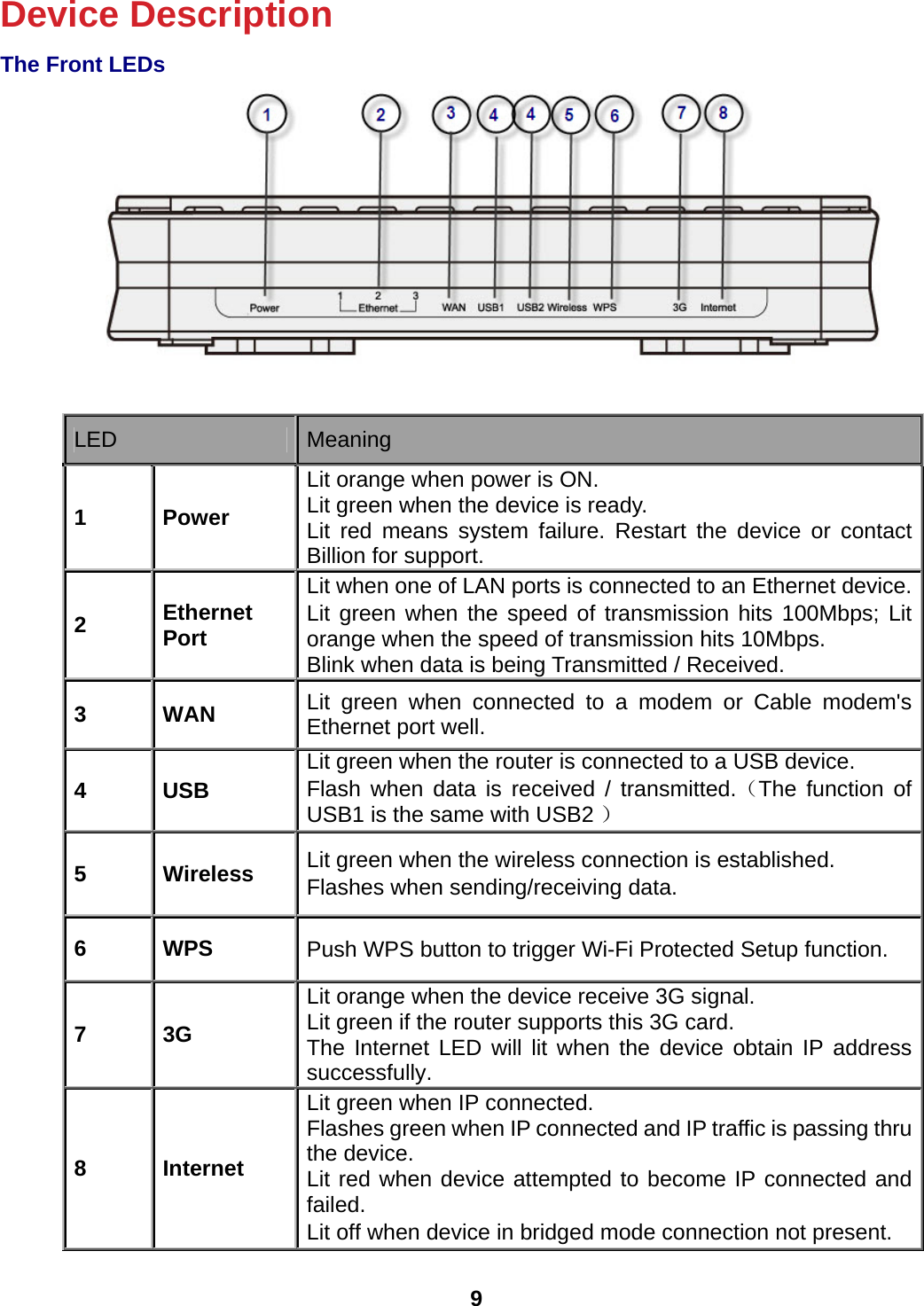
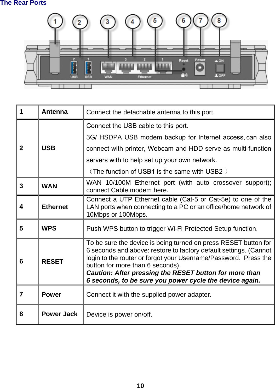
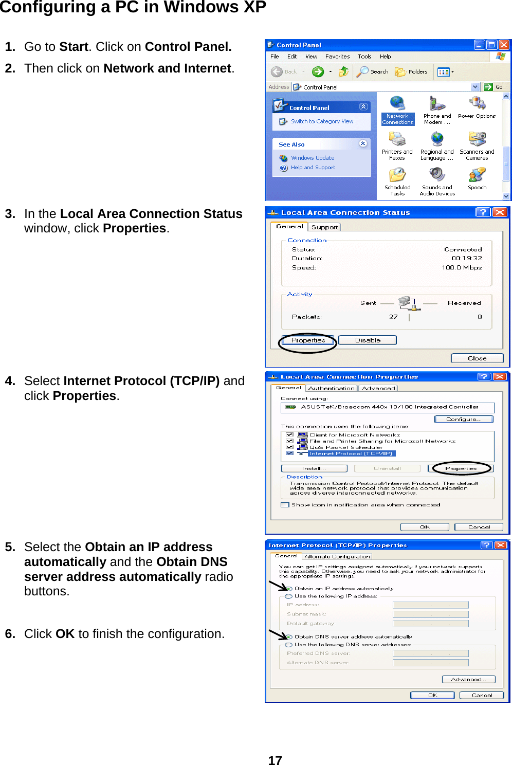
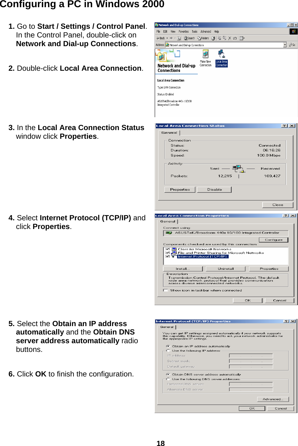
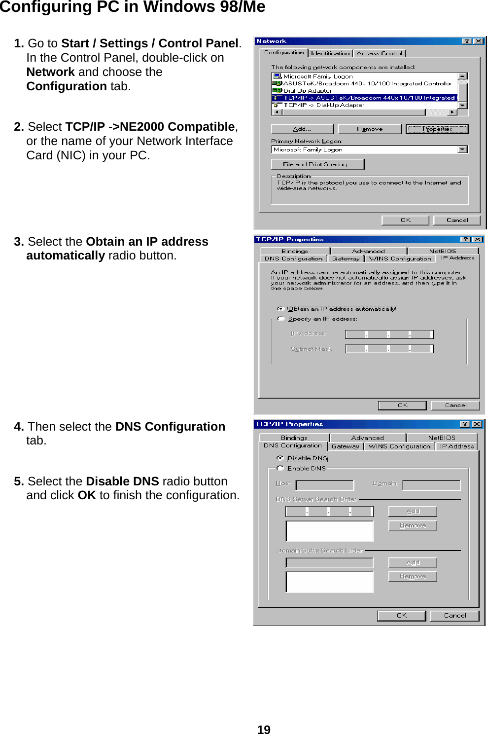
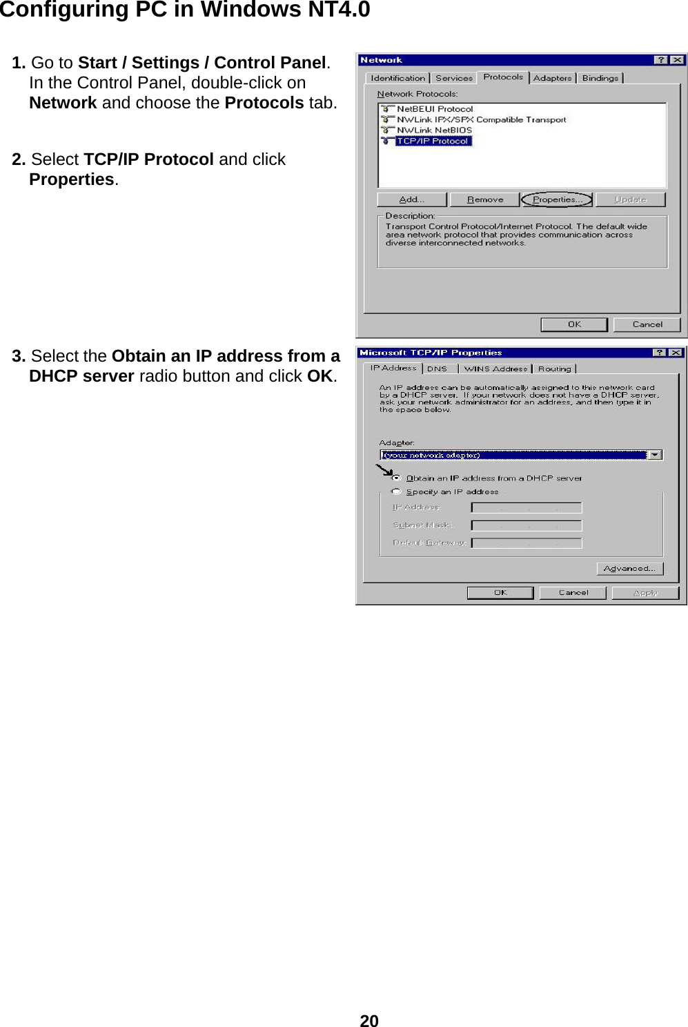
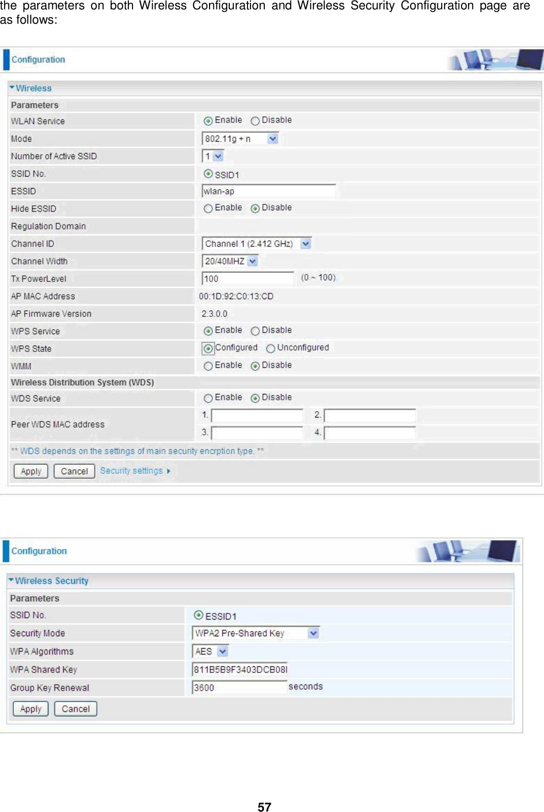
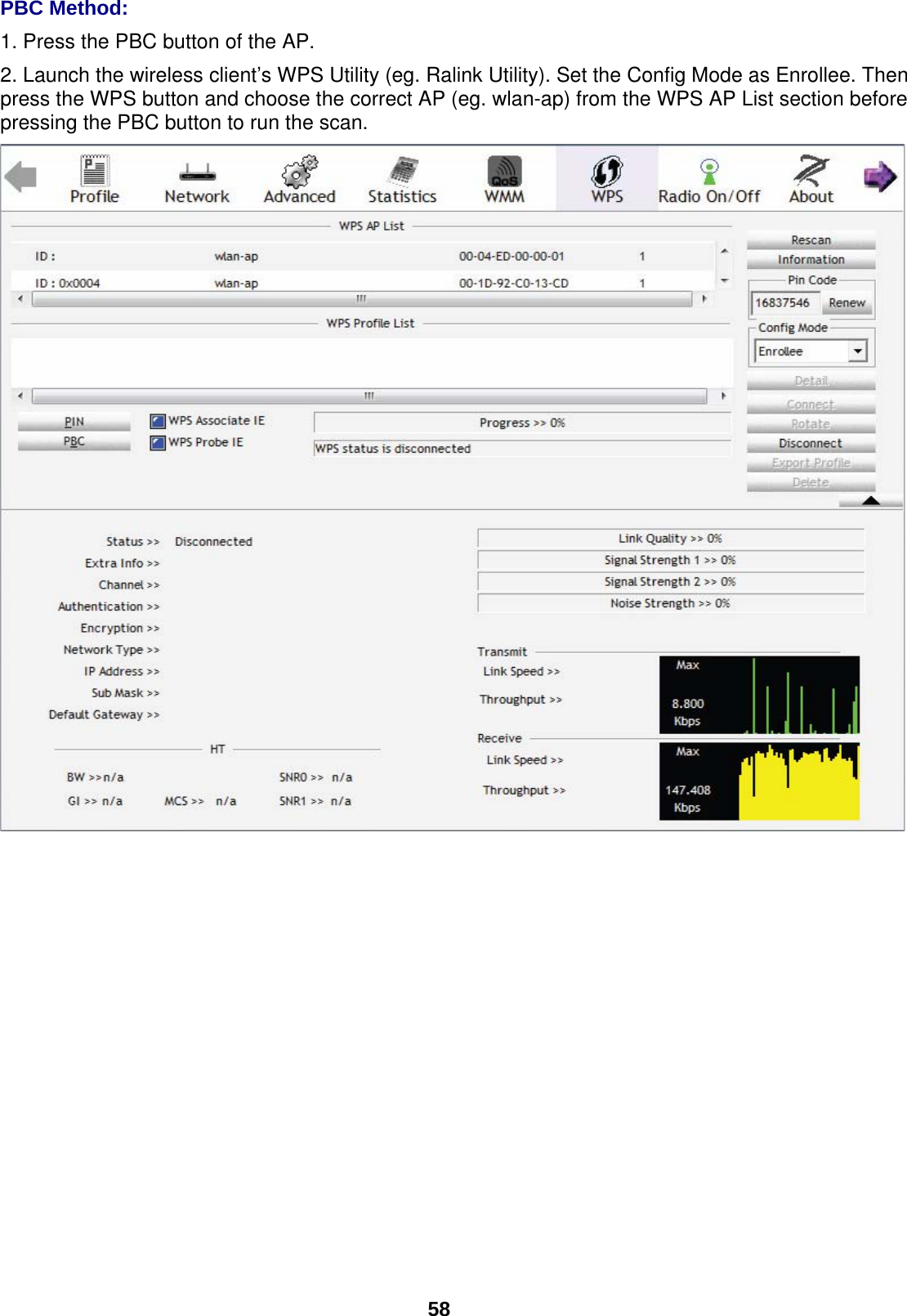
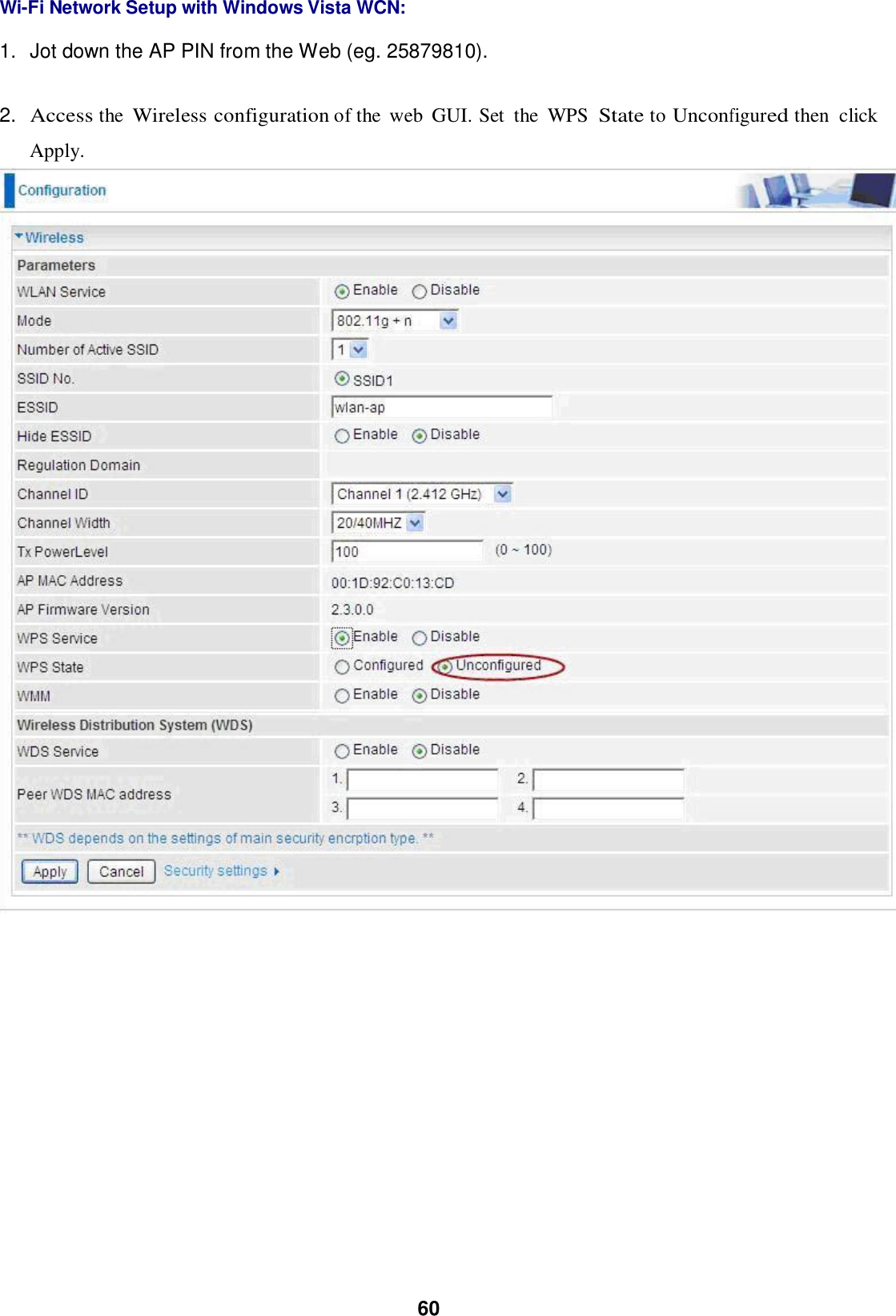
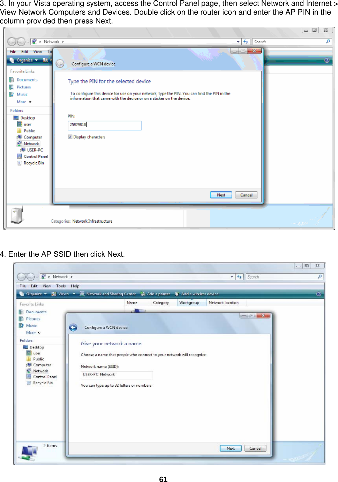
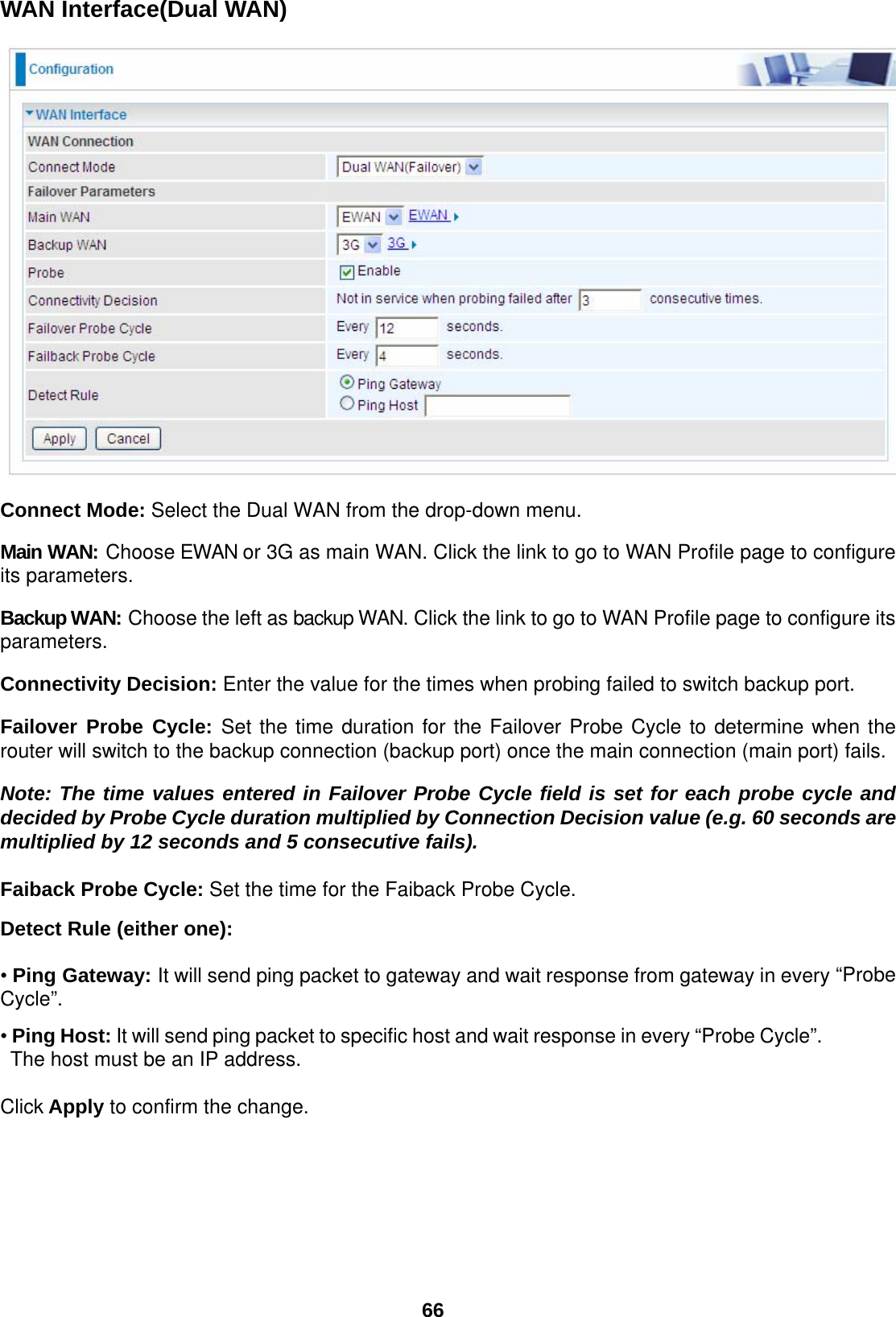
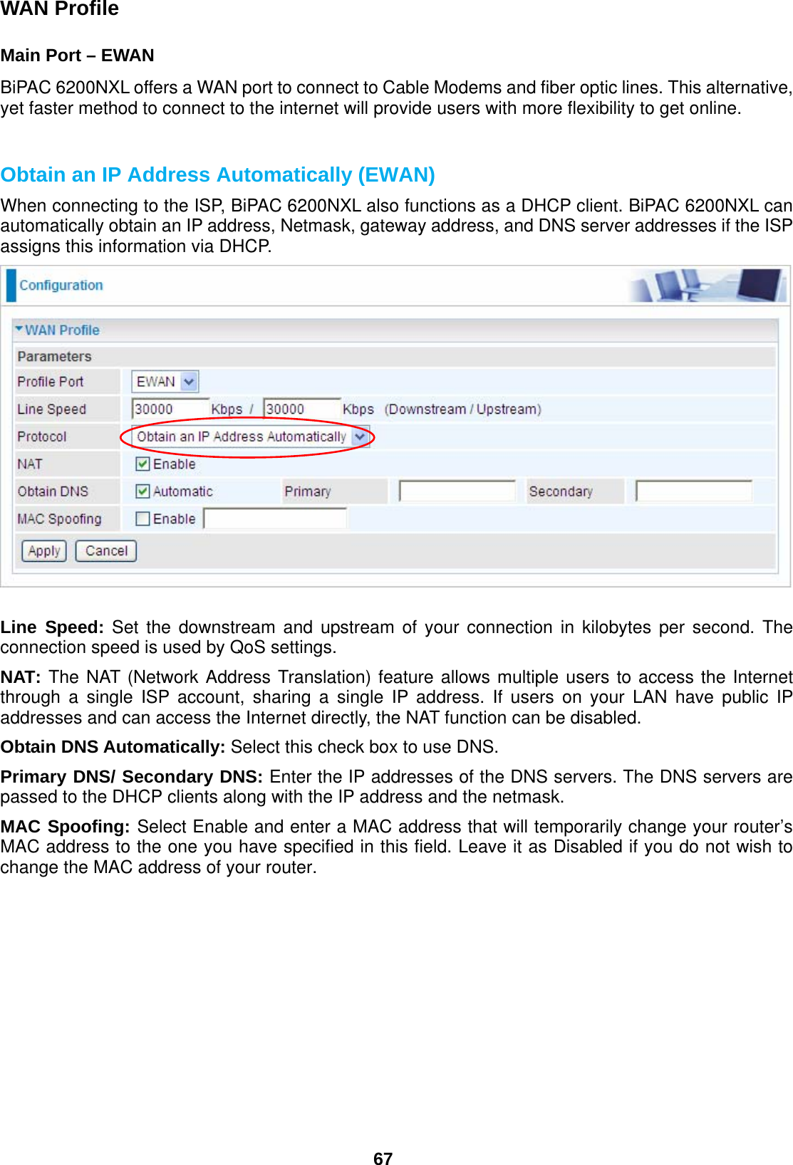
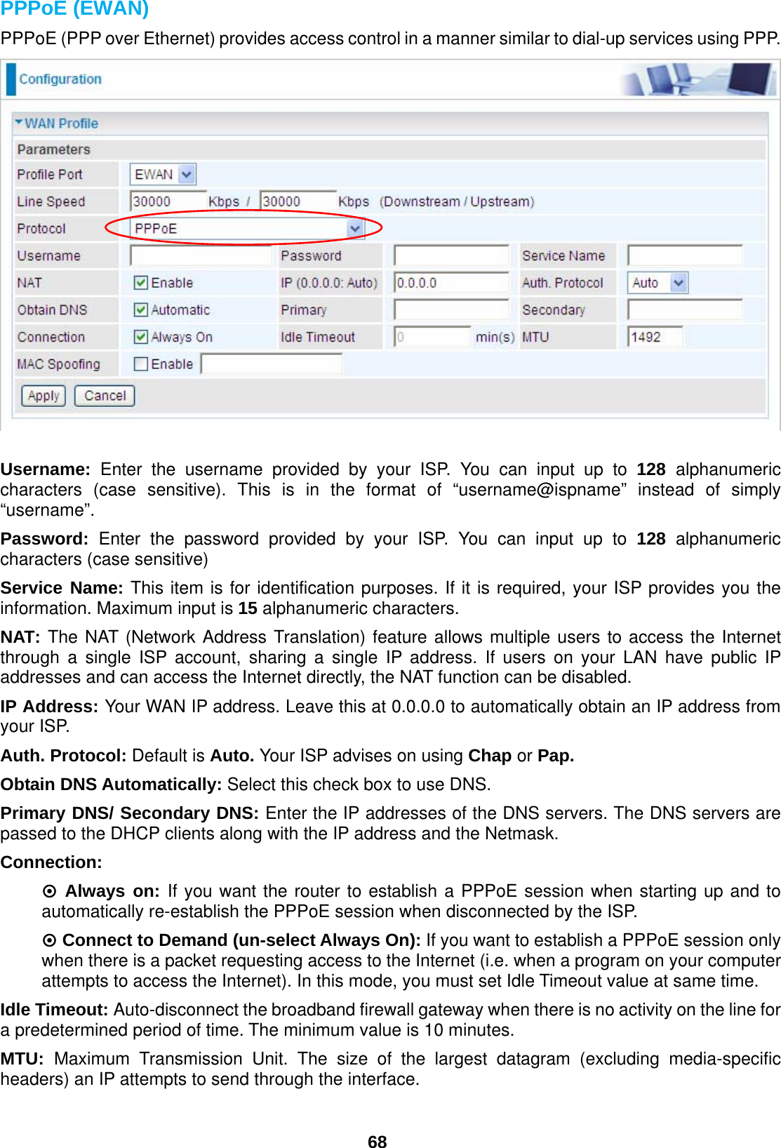
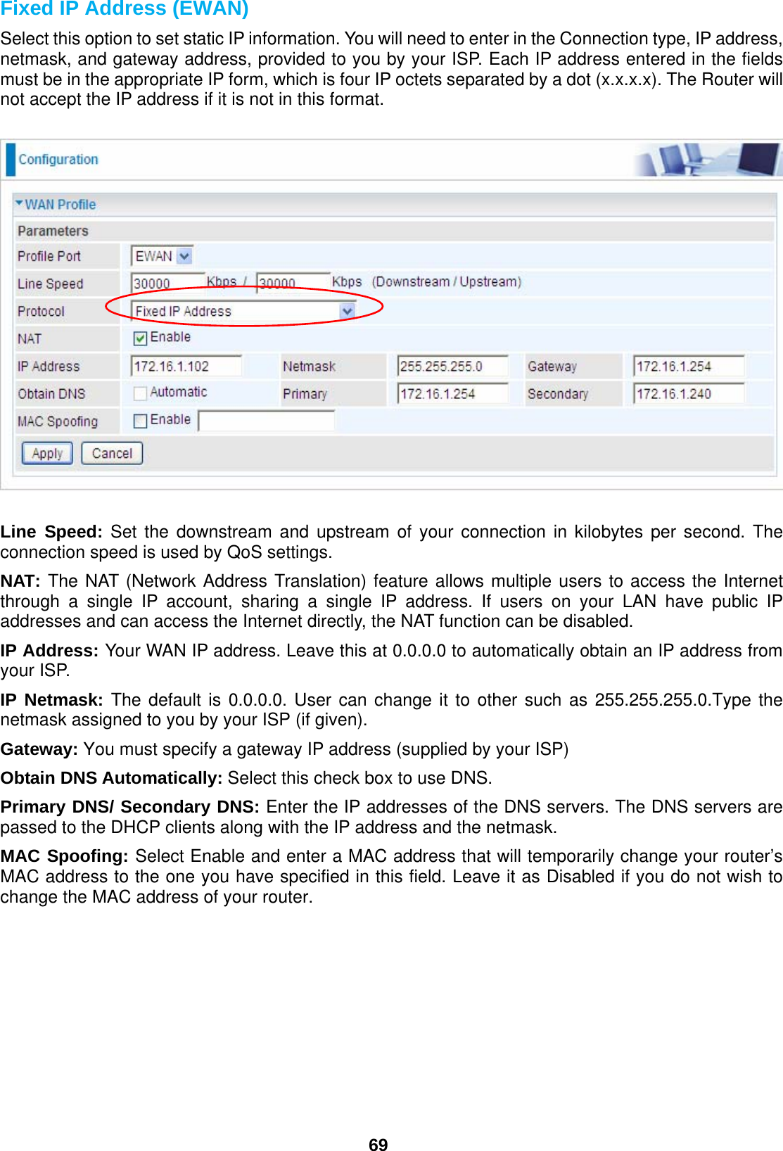
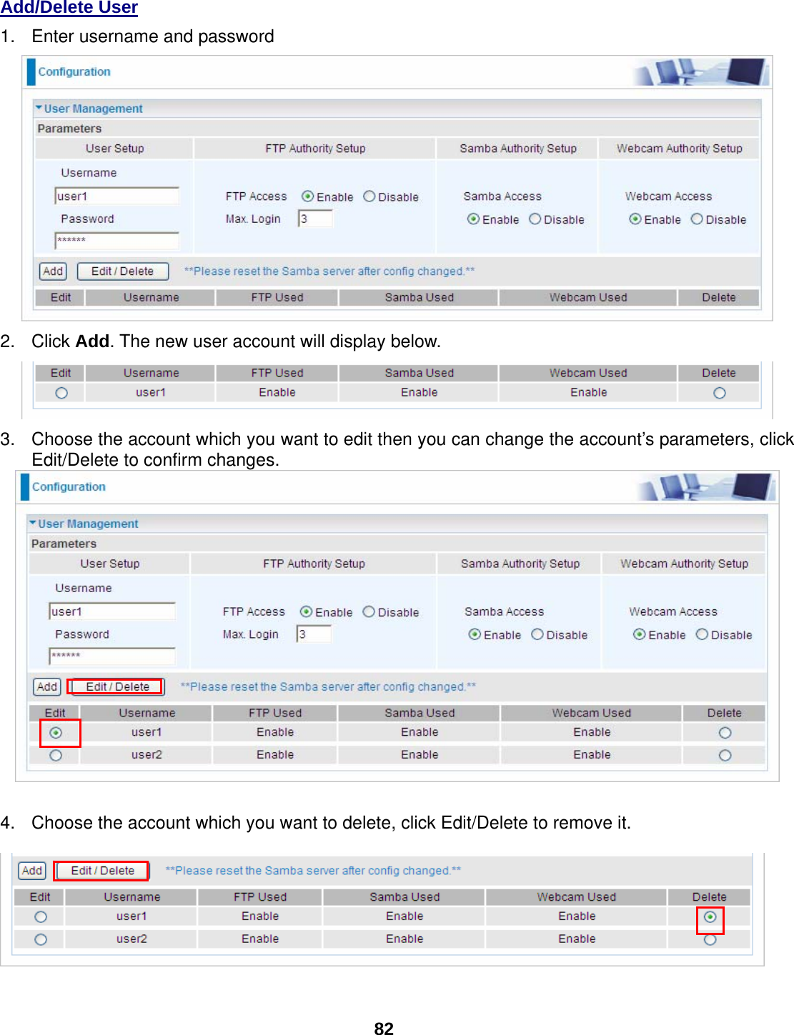
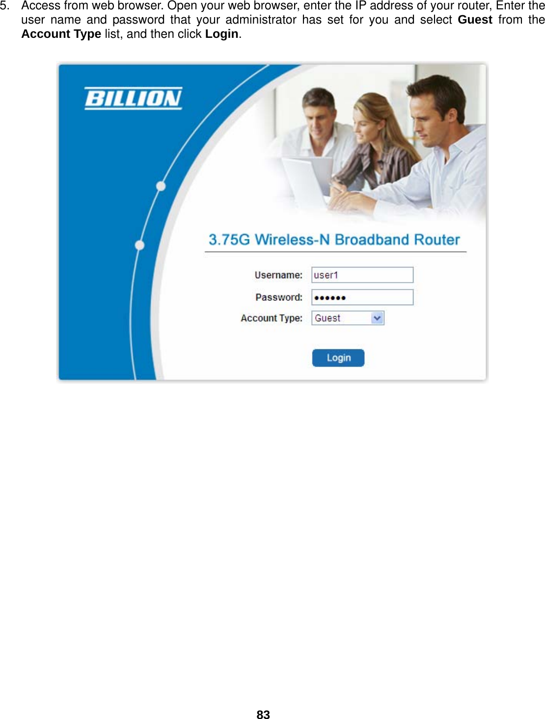
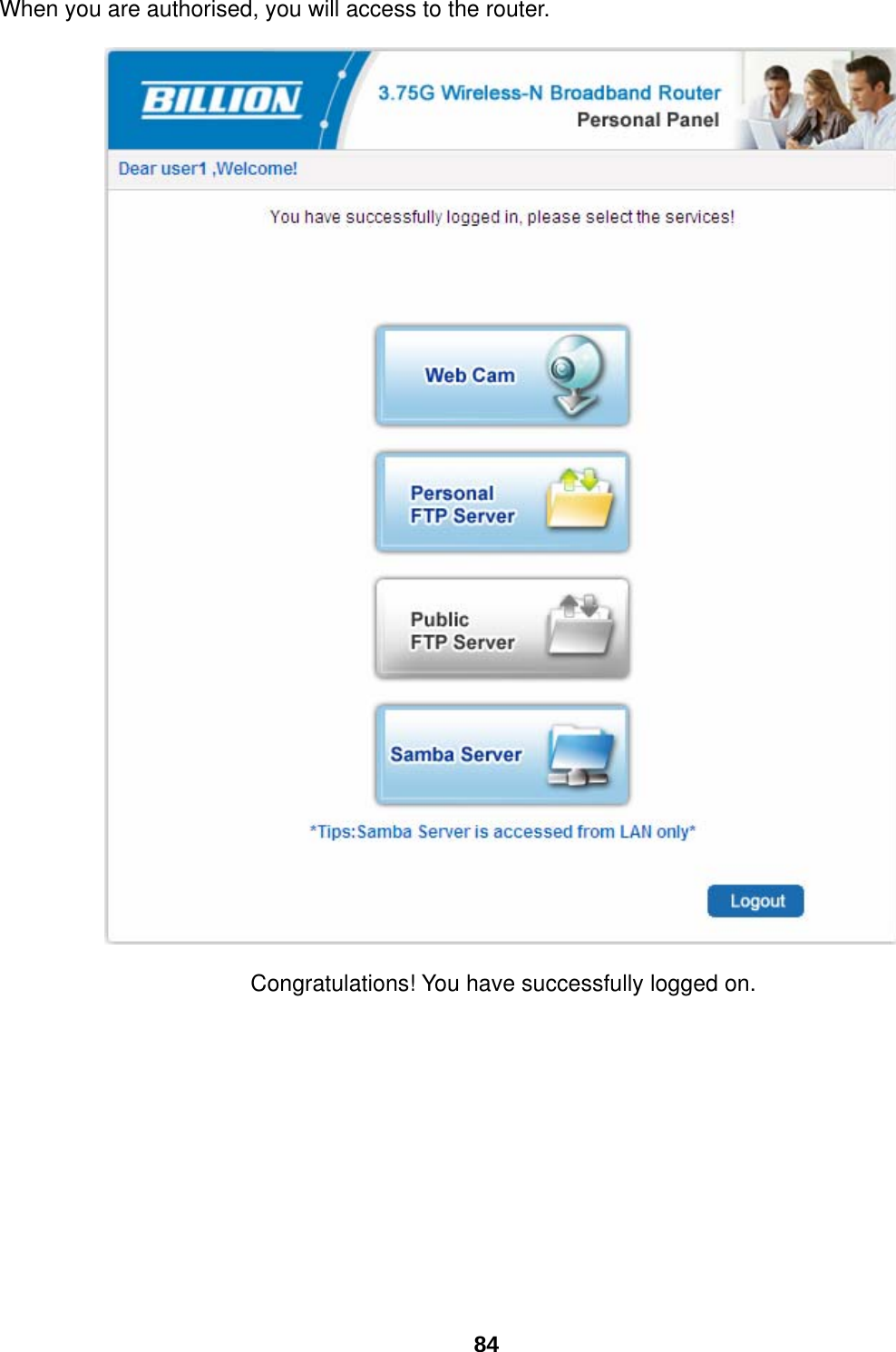
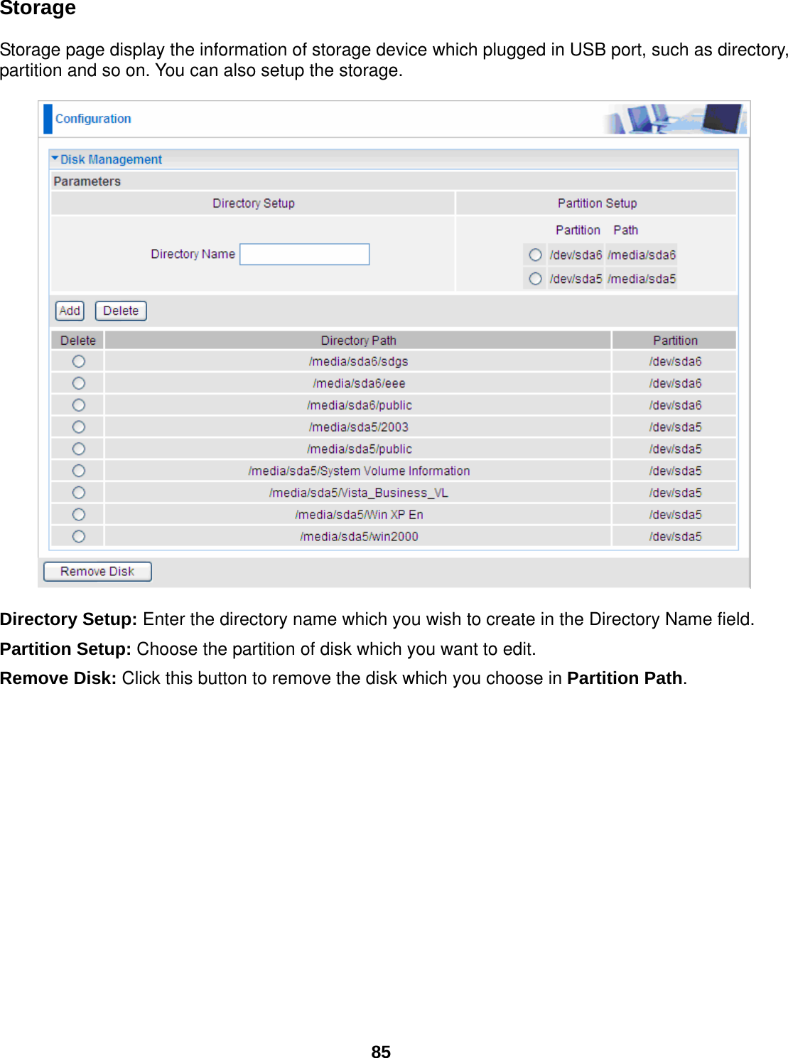
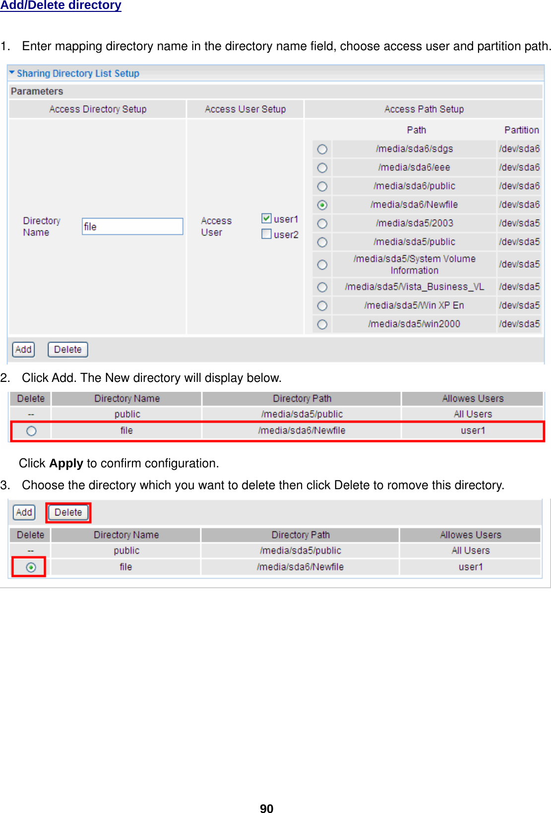
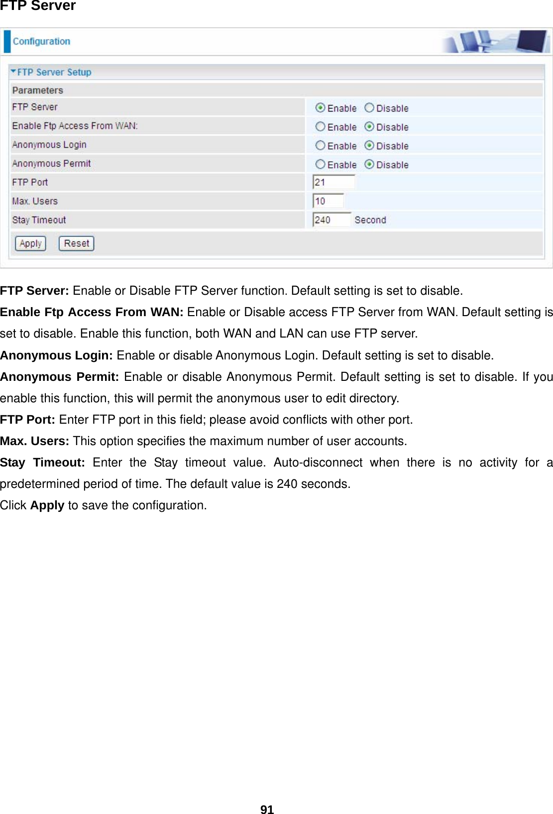
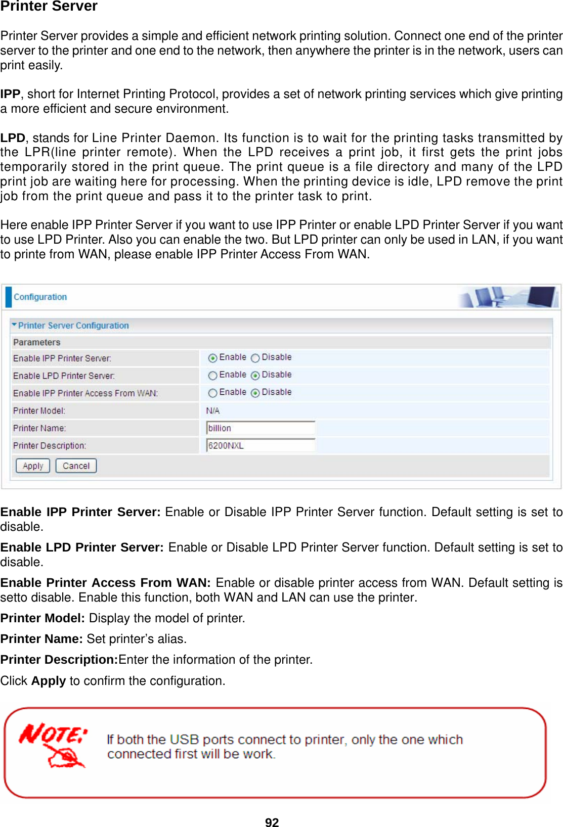
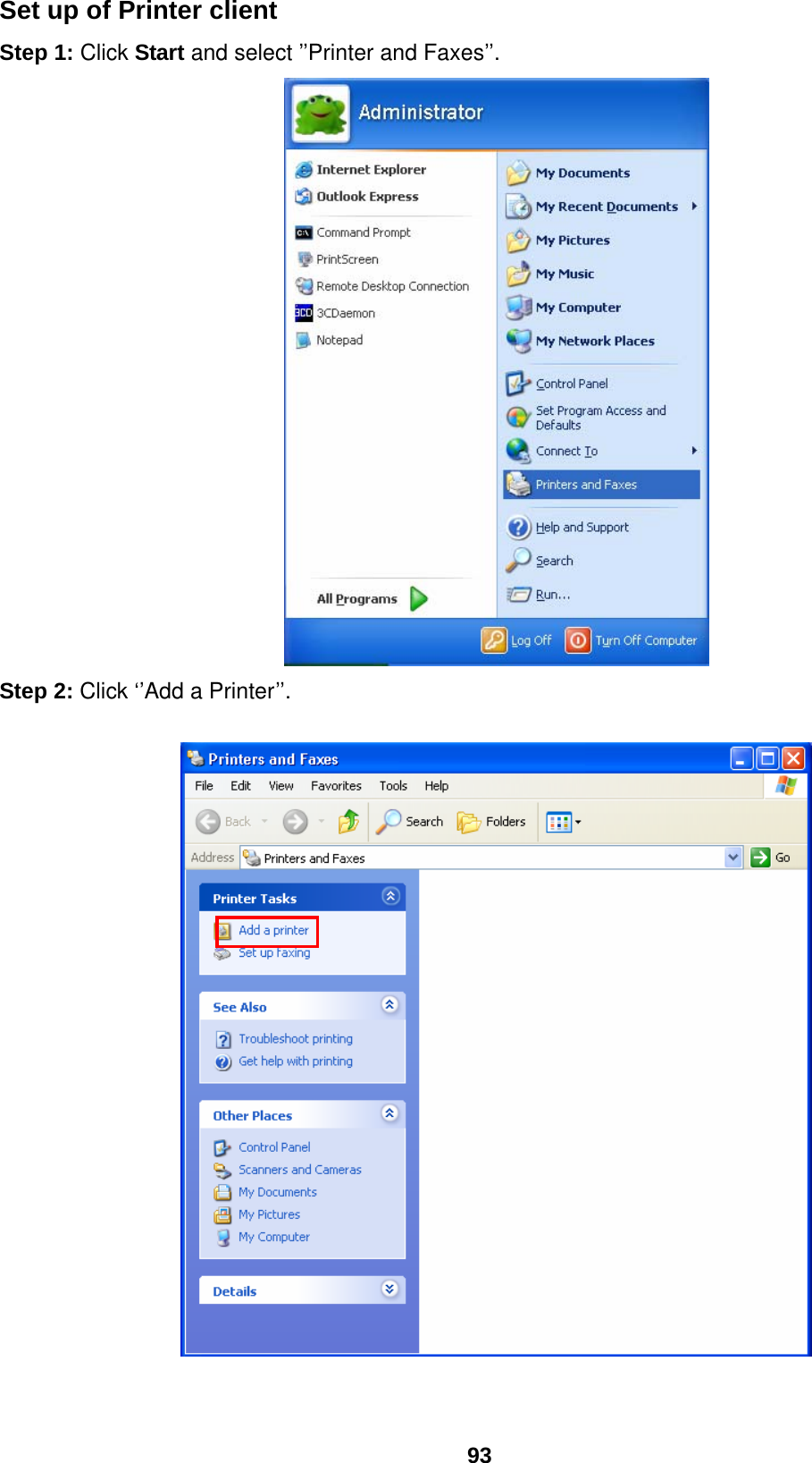
Billion Electric BIL-6200NXL 3.75G Wireless-N Broadband Router User Manual
Billion Electric Co., Ltd. 3.75G Wireless-N Broadband Router
UserManual.wiki
>
Billion Electric
>
BIL 6200NXL User Manual
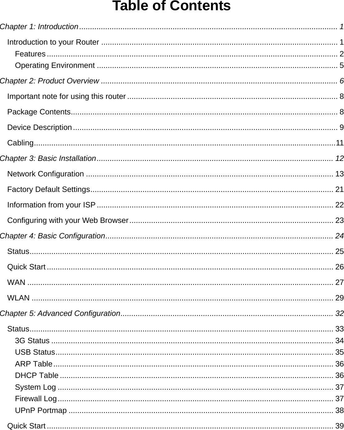
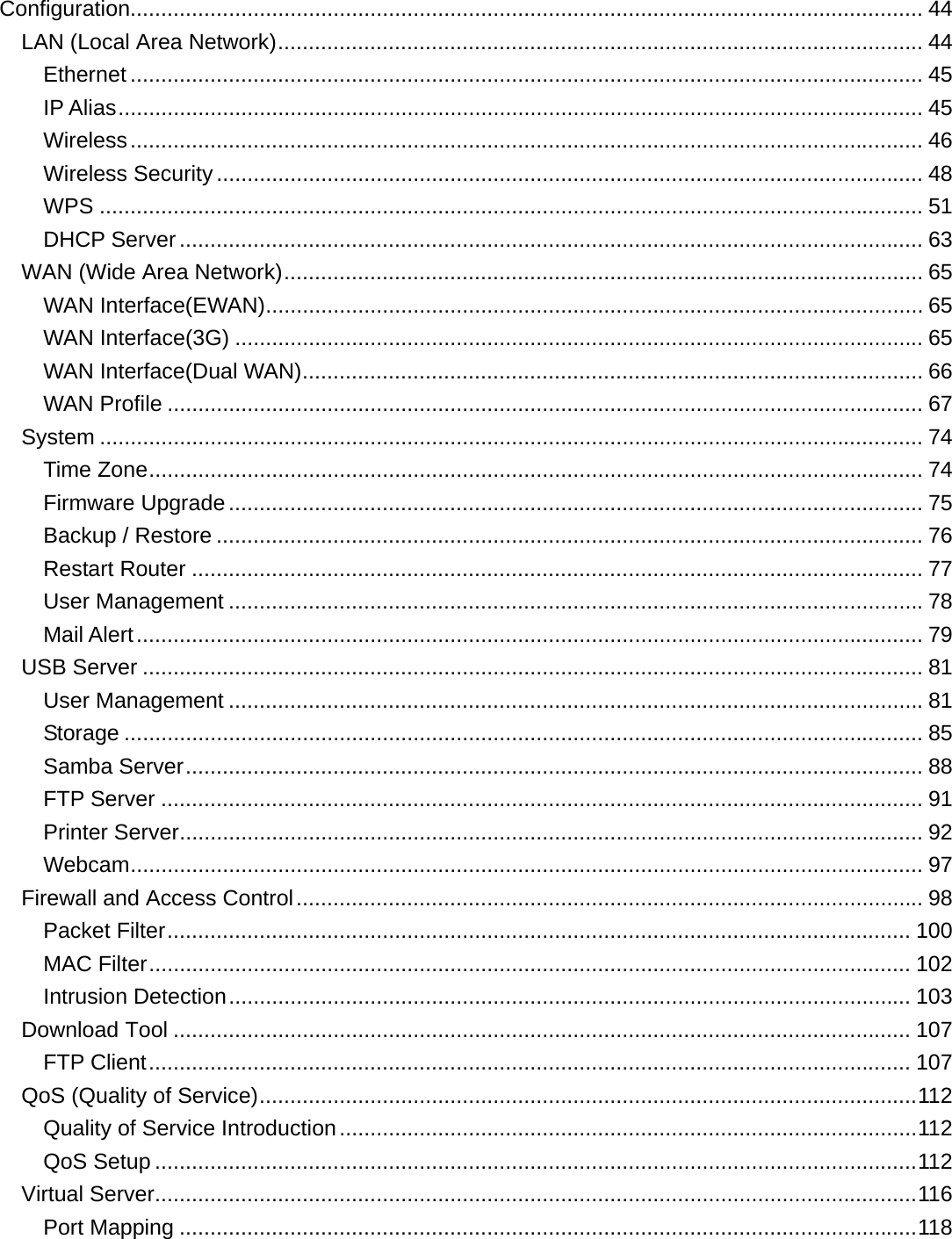
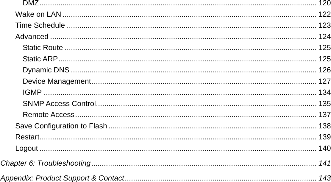
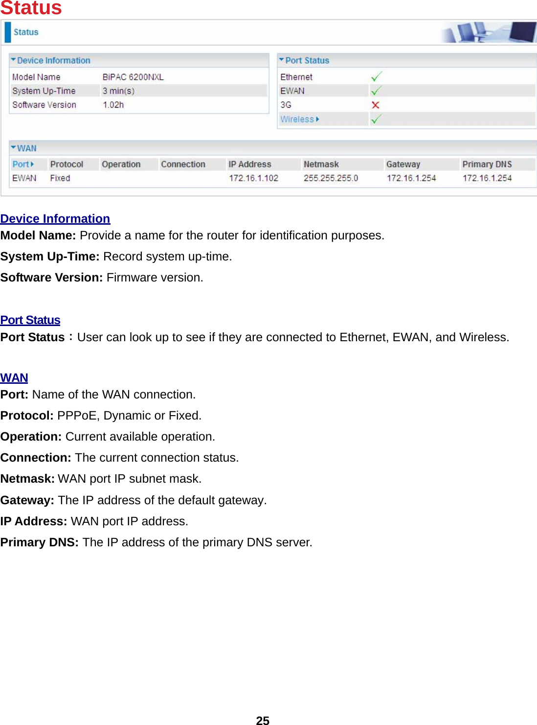
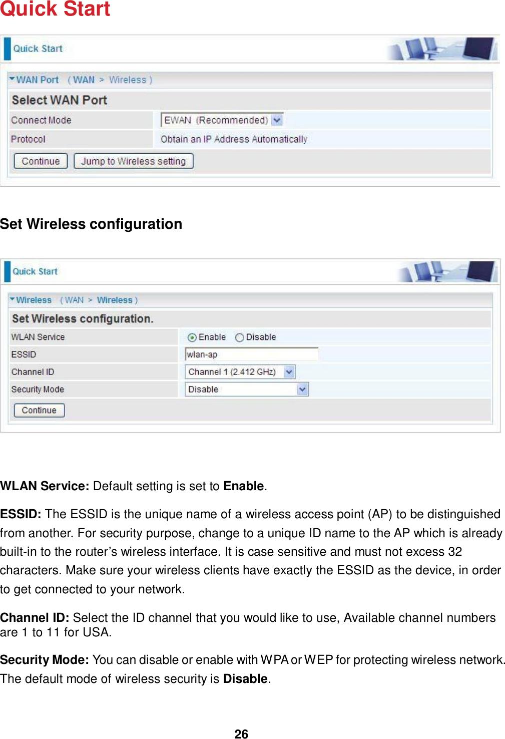
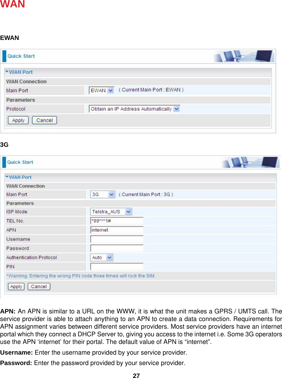
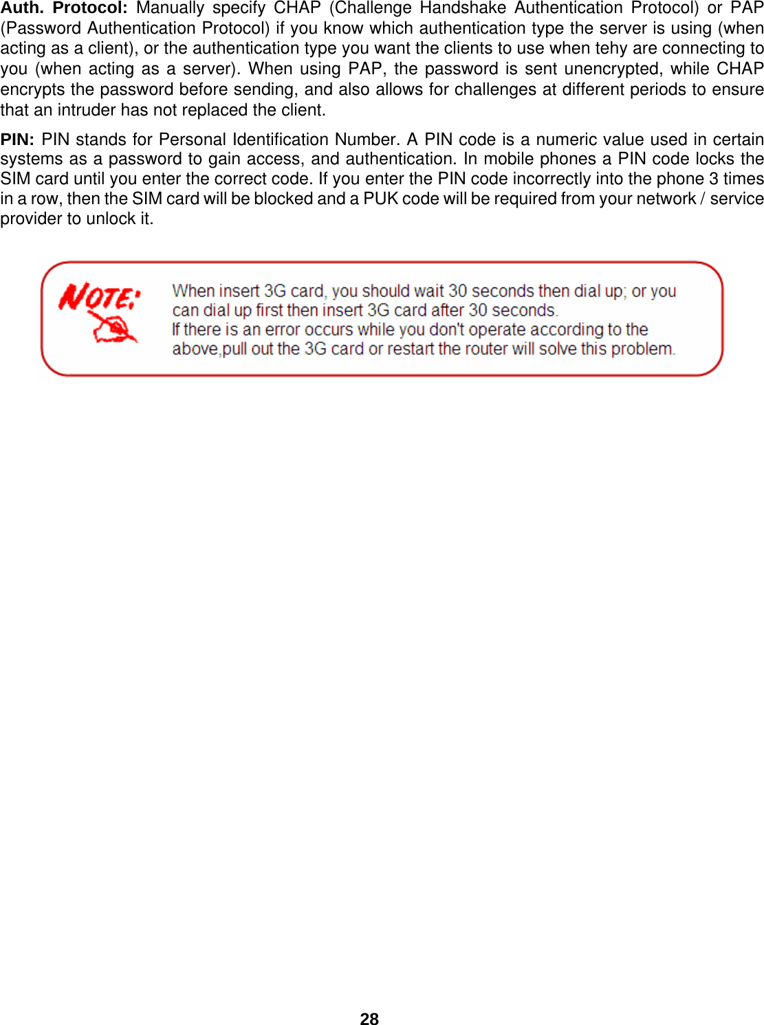
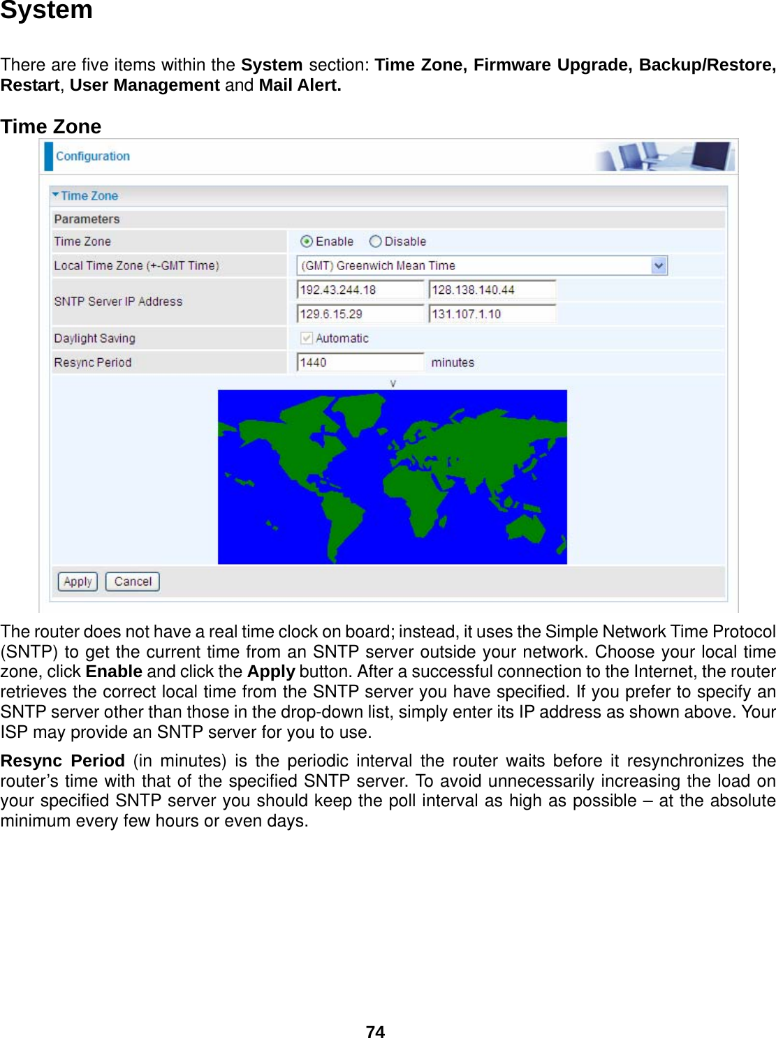
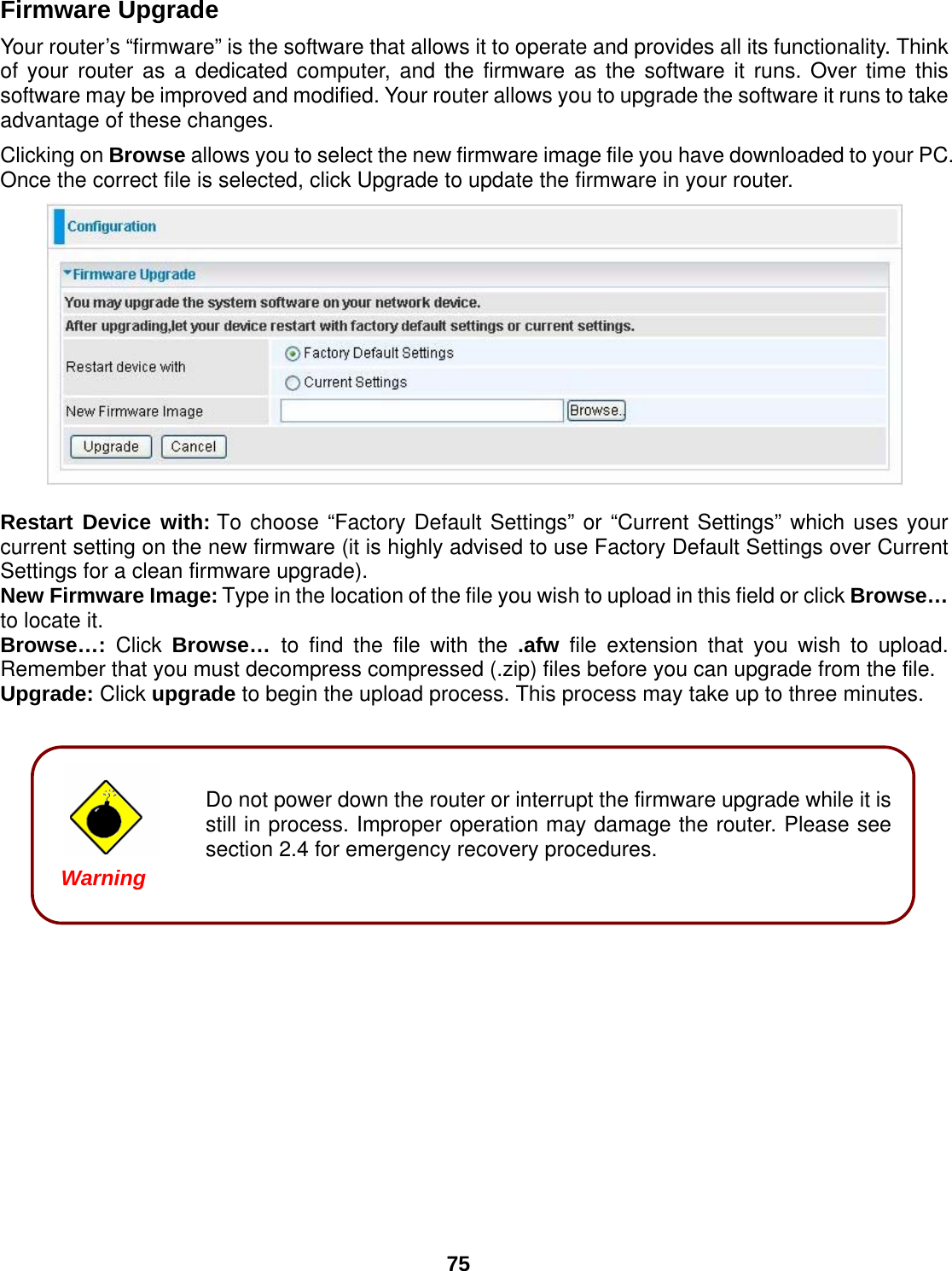
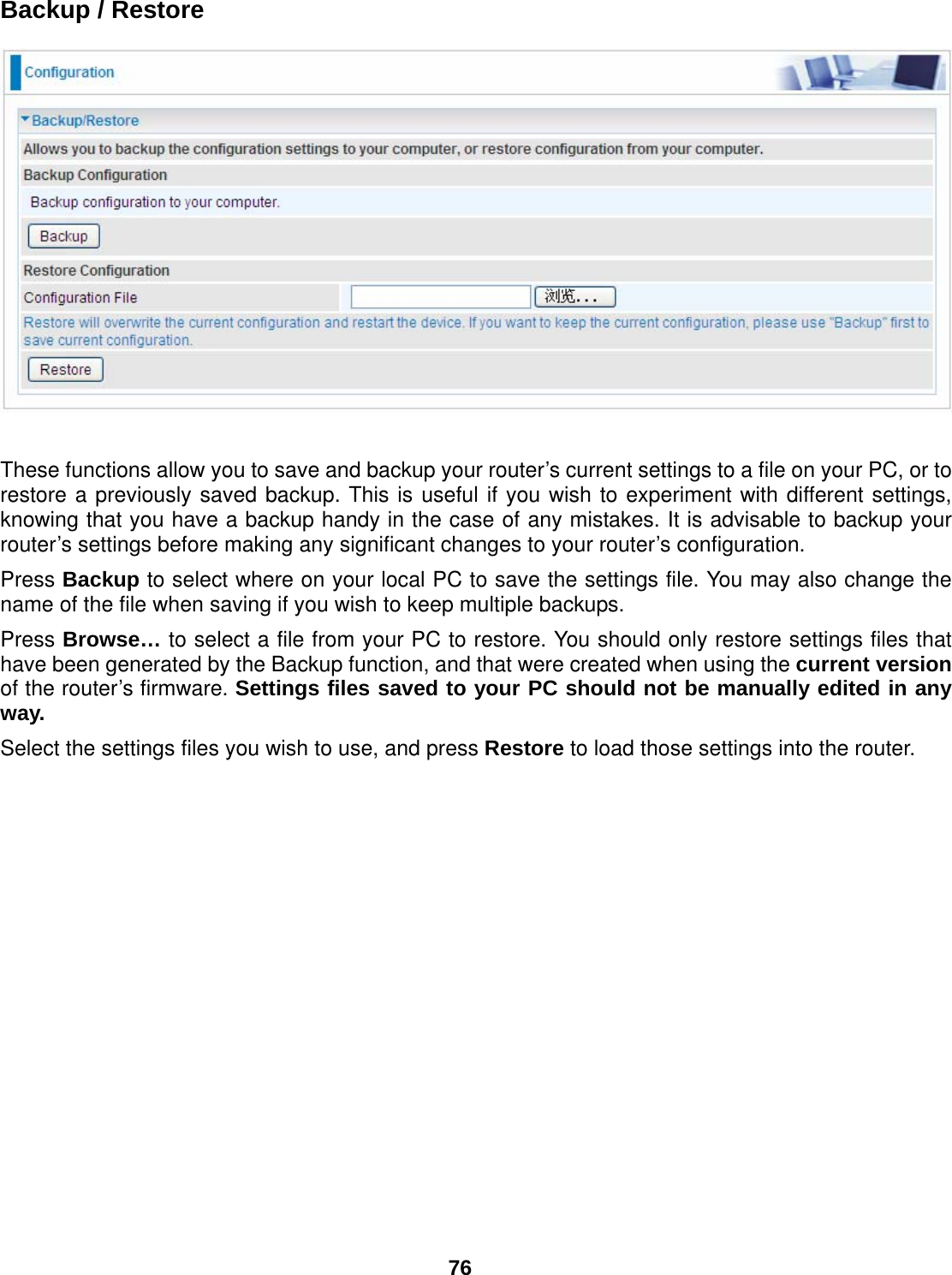
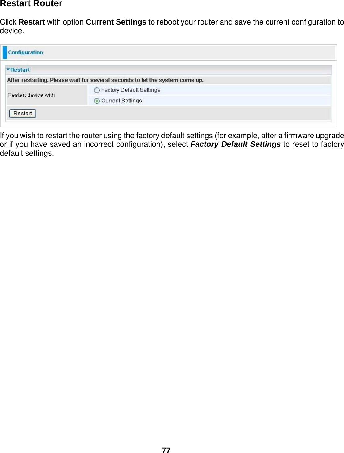
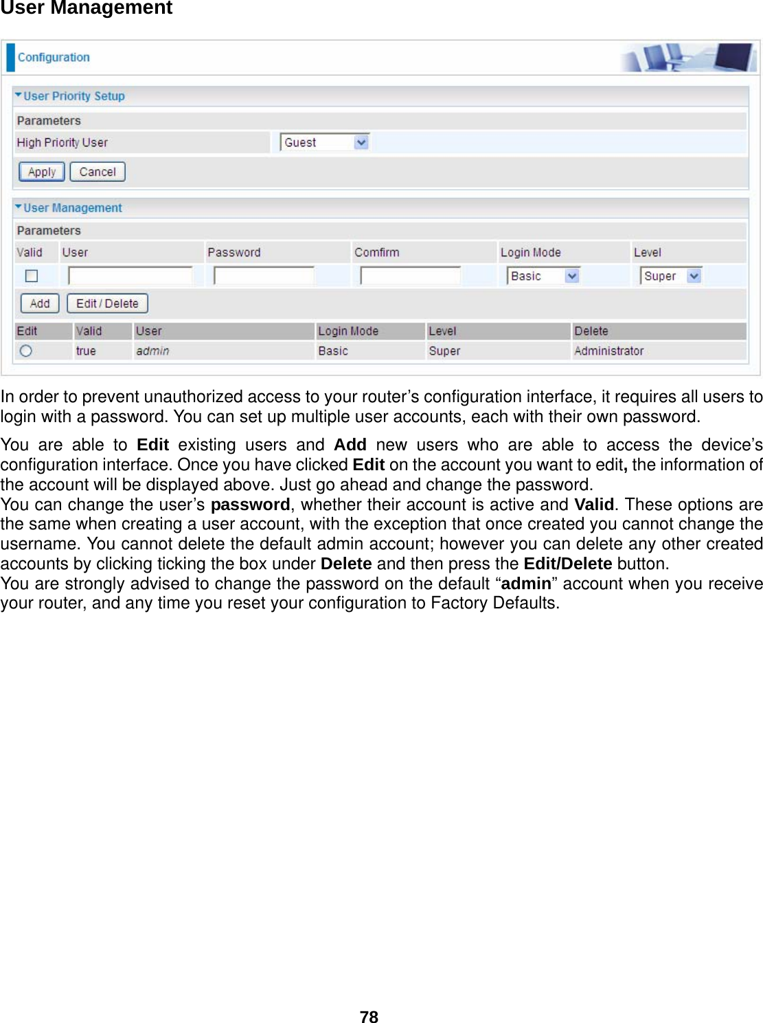
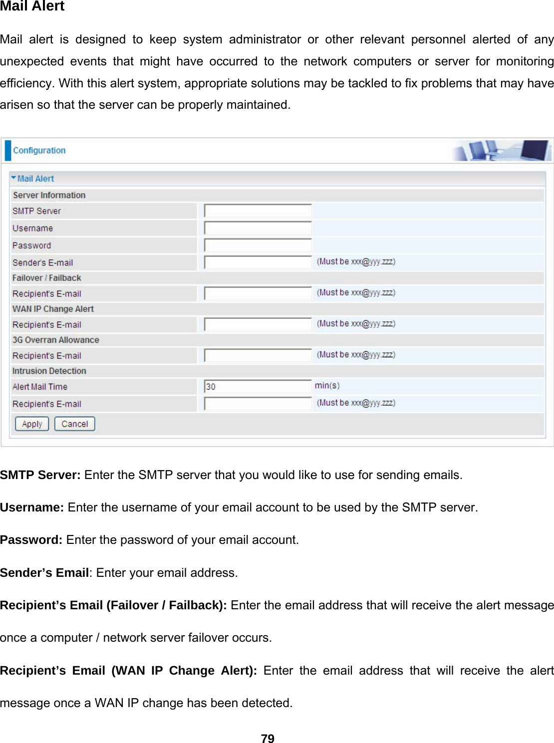
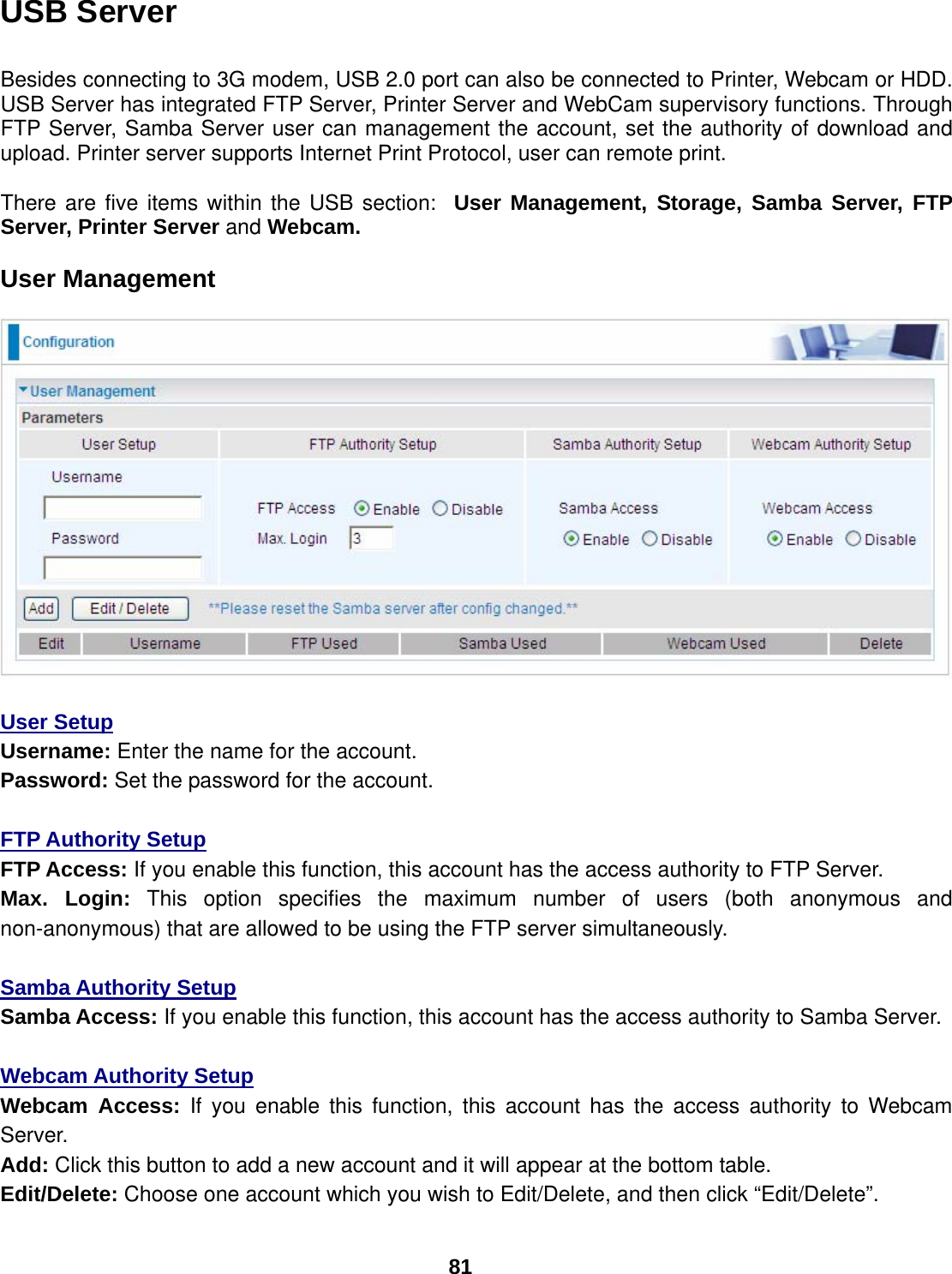
User Manual
Navigation menu
Upload a User Manual
Namespaces
Wiki Guide
HTML
PDF
Info
Views
User Manual
Discussion / Help
Navigation