Billion Electric BIL-7401VGPR4 VoIP/ (802.11g) ADSL2+ Firewall Router User Manual
Billion Electric Co., Ltd. VoIP/ (802.11g) ADSL2+ Firewall Router
UserManual.wiki
>
Billion Electric
>
BIL 7401VGPR4 User Manual
user manual
Navigation menu
Upload a User Manual
Namespaces
Wiki Guide
HTML
PDF
Info
Views
User Manual
Discussion / Help
Navigation


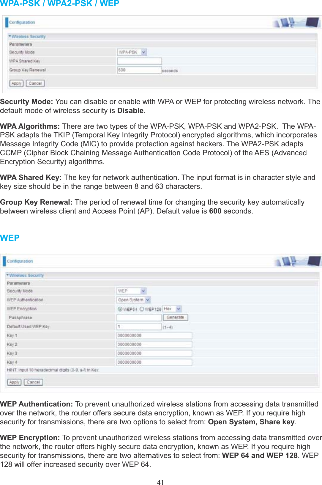
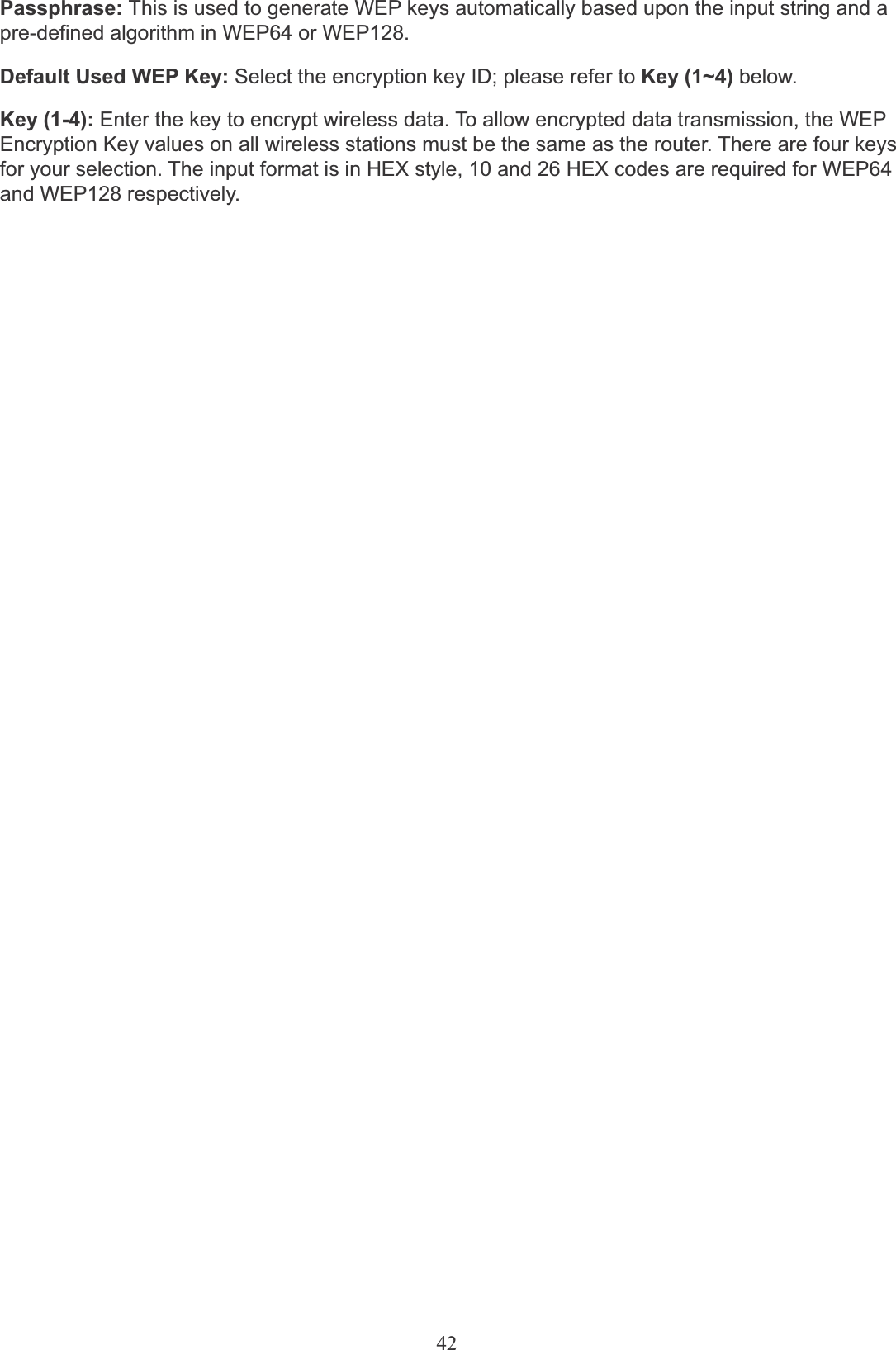


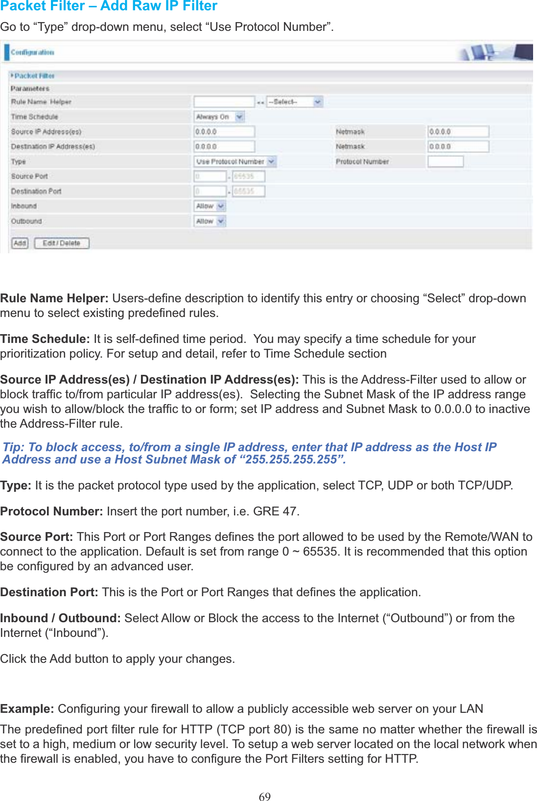
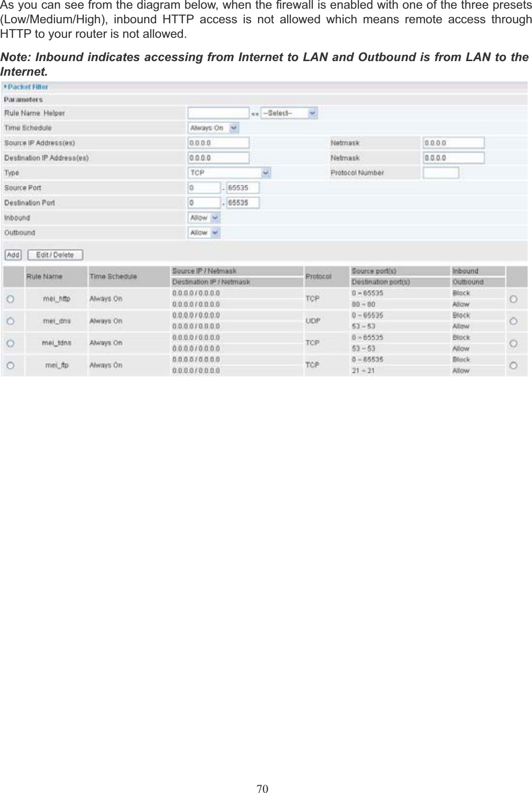


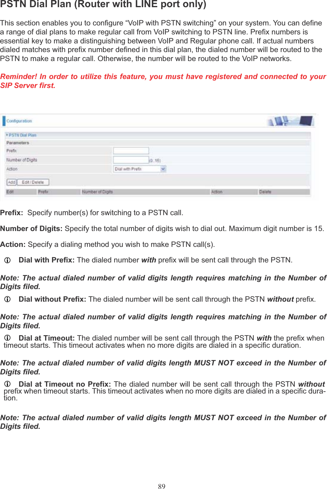
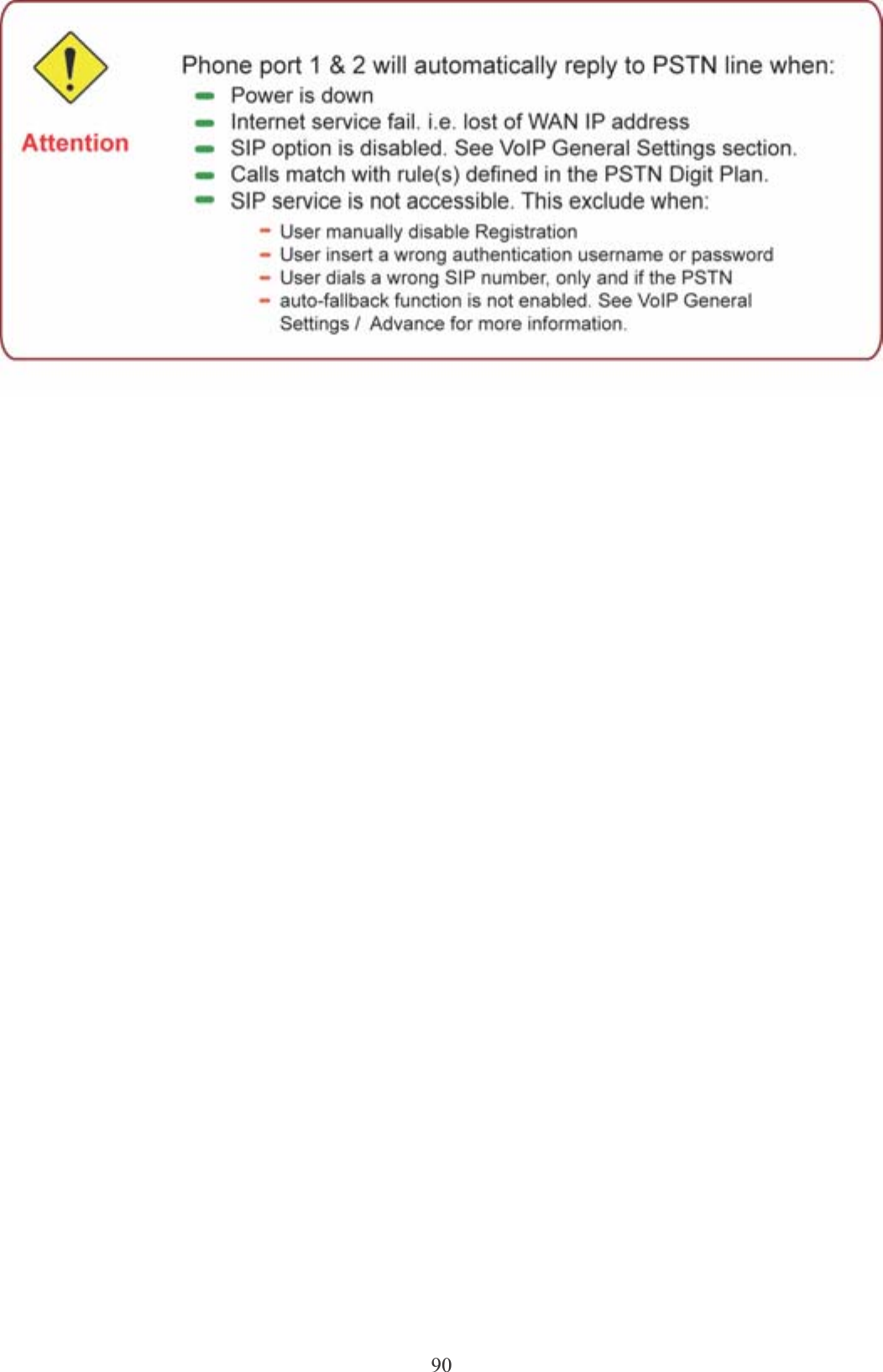
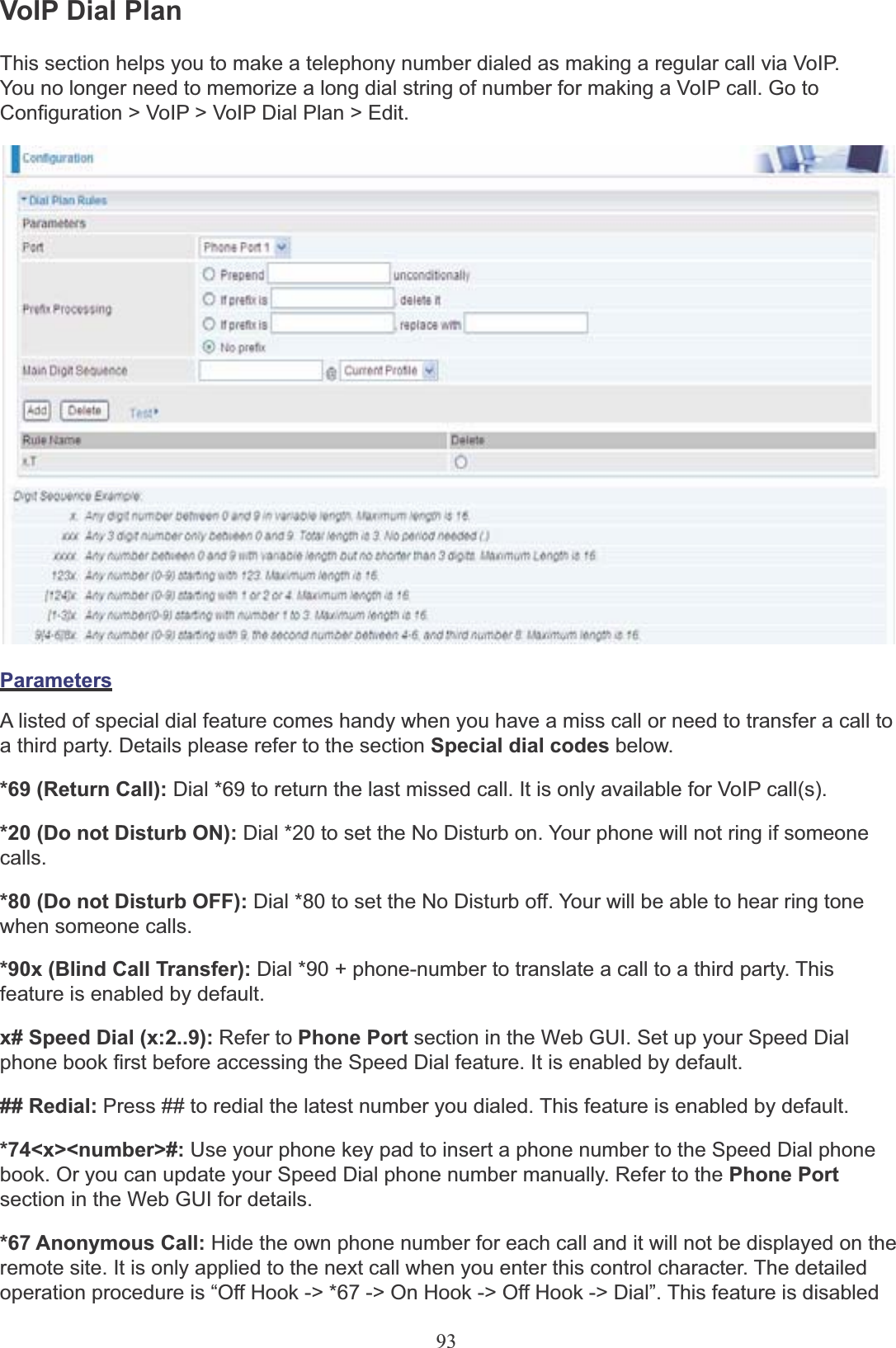

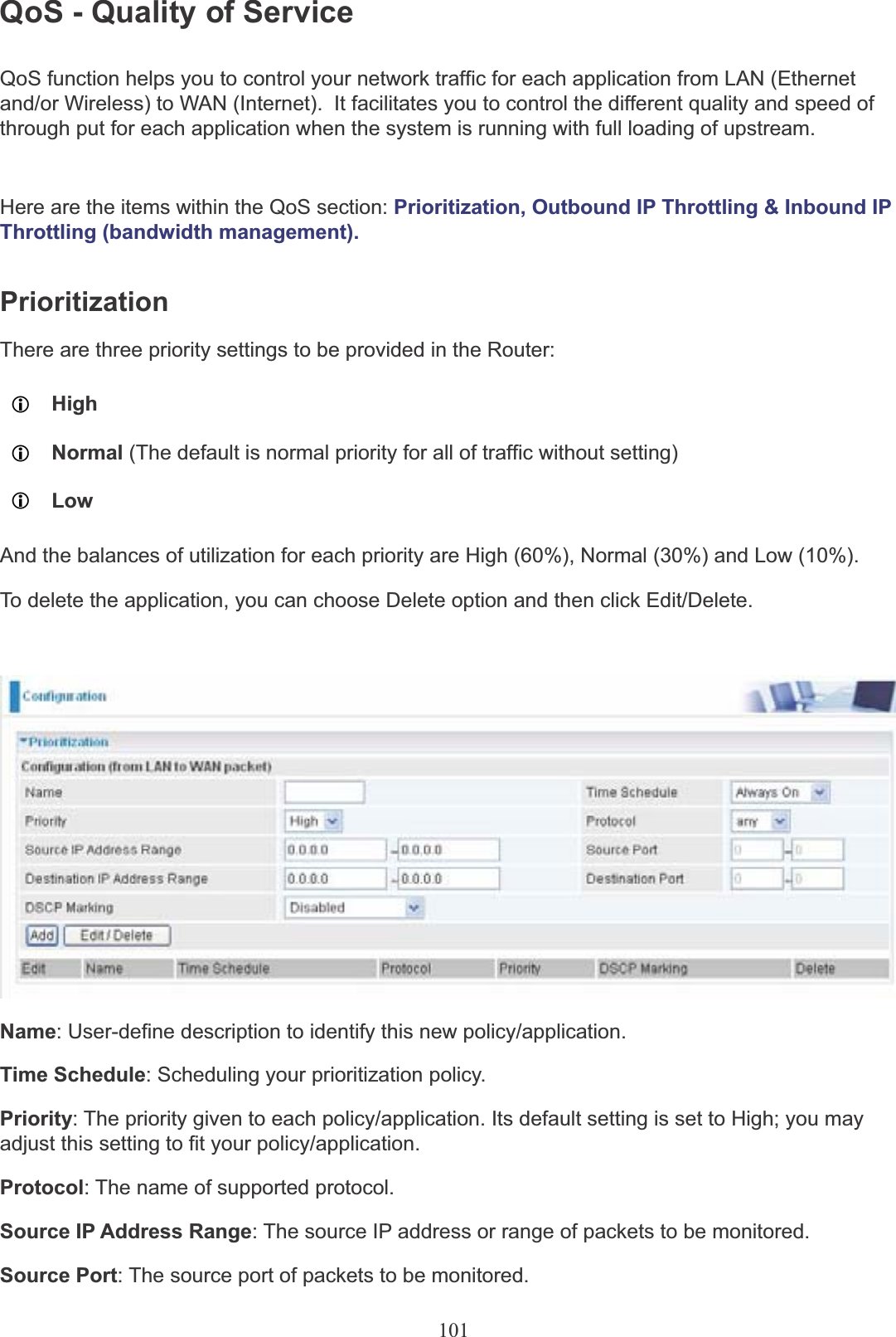
![96<@ Current Profile>: Referring to the VoIP account registered on the VoIP Wizard for Port 1 / 2.<@ PSTN>: Meaning making call(s) via the PSTN line.<@ENUM>: Meaning making a VoIP SIP direct call via E.164 number (“ENUM”) to an ENUMcallee.Electronic Number (ENUM) uses the DNS (Domain Network System) based technology to map between a traditional phone number (PSTN) to an Internet addresses/ SIP URL. The ENUM number must be registered via a public ENUM site or your VoIP Service Provider.<@ SIPgateway>: It is used for the Intelligent Call Routing feature where you need to set upyour SIP account on the VoIP User-defined Profiles link on the VoIP Wizard page. Go to the VoIPWizard in this manual for more information.Dial-Plan Examples: Descriptionx. Any digit number between 0 and 9 in variable length. Maximum length is 16.xxx Any 3 digit number only between 0 and 9. Total length is 3.Note: No period is needed (.)xxxx. Any number between 0 and 9 with variable length but no shorter than 3 digits. Maximum length is 16.123x. Any number (0-9) starting with 123. Maximum length is 16.[x…x]x.For example: [124]x.Any number (0-9) starting with 1 or 2 or 4. Maximum length is16.[x-x]x.For example: [1-3]x.Any number (0-9) starting with number 1 to 3. Maximum length is16.x[x-x]x.For example: 9[4-6]8x.Any number (0-9) starting with 9, the second number between4-6, and third number 8. Maximum length is 16.Special Dial PlanExamples: Description*xx*x. Starting with ‘* sign’ + any two digit numbers + any number (0-9)in variable length. Maximum length is 16.*xxStarting with ‘* sign’ + any 2 digit numbers between 0 and 9. Total length including the * is 3.Note: No period is needed (.)**xx*x. Starting with ‘** sign’ + any two digit numbers between 0 + any number (0-9) in variable length. Maximum length is 16.#xx. Starting with ‘# sign’ + any digit number (0-9) in variable length but no shorter than 1 digits. Maximum length is 16.##xx*x. Starting with ‘## sign’ + any two digit numbers + ‘* sign’ + any number (0-9) in variable length. Maximum length is 16.Intelligent Call Routing Example:VoIP Gateway let you use 3 VoIP/SIP providers at the same time. VoIP/SIP providers are](https://usermanual.wiki/Billion-Electric/BIL-7401VGPR4/User-Guide-1201813-Page-100.png)
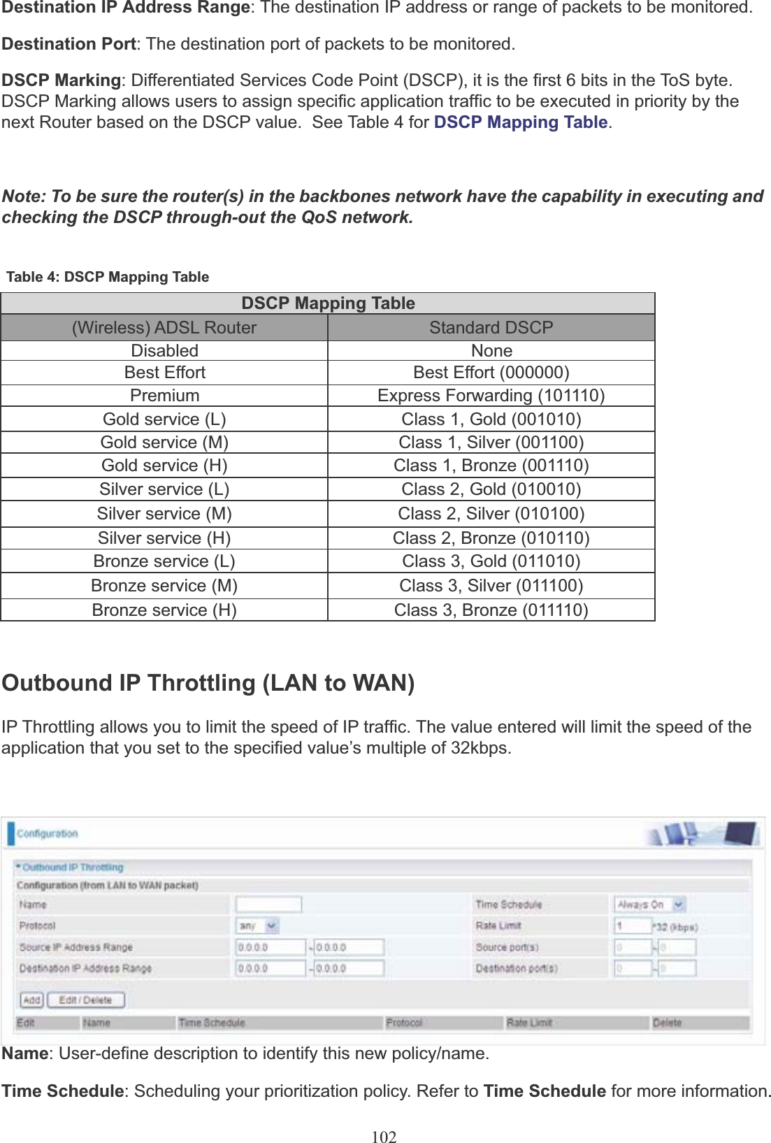
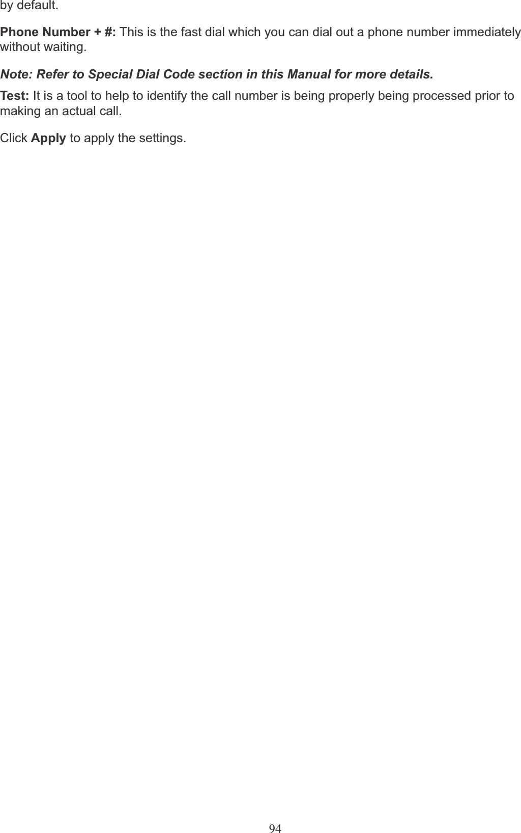
![97localcheap.com,longdischeap.com and mobilecheap.com. Each provider has its price for different type of calls and I can set the following rule for each providers.1. Phone 1: For Local calls: I use localcheap.com that charges $0.01 per minute to all local calls. Iset a dial rule, <:03>[123]x.T, on my phone port 1.Localcheap.com is the default VoIP provider I set on phone port 1. When I call out any numberstart with 1 or 2 or 3 and plus rest of the phone number for local call, 03 is always prepended in front of these number. If 23295 are dialed, 03-2-32935 is the actual phone number called out via localcheap.com provider.2. Phone 2: For Mobile calls: I use mobilecheap.com that charges $0.25 per minute to all local calls.I set a dial rule, <123:09>39x.T, on my phone port 2.Mobilecheap.com is the default VoIP provider I set on phone port 2. When I call out 123-39-45678for a mobile call, 123 is replaced with 09. Therefore, 09-39-45678 is the actual phone number called out via Mobilecheap.com provider.The Intelligent Call Gateway not only saves time from changing VoIP settings to different provider to make call get routed to specific gateway(s) automatically but also taking advantage of different call rate.](https://usermanual.wiki/Billion-Electric/BIL-7401VGPR4/User-Guide-1201813-Page-101.png)