Billion Electric BIL-7404VGOXC 3G / VoIP/ 802.11g ADSL2+ VPN Firewall Router User Manual BiPAC 7404V G OX
Billion Electric Co., Ltd. 3G / VoIP/ 802.11g ADSL2+ VPN Firewall Router BiPAC 7404V G OX
UserManual.wiki
>
Billion Electric
>
BIL 7404VGOXC User Manual
user manual
Navigation menu
Upload a User Manual
Namespaces
Wiki Guide
HTML
PDF
Info
Views
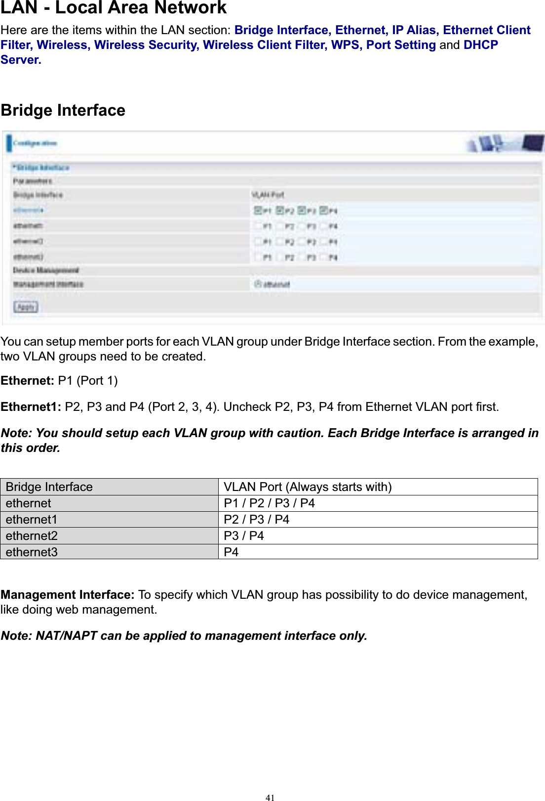
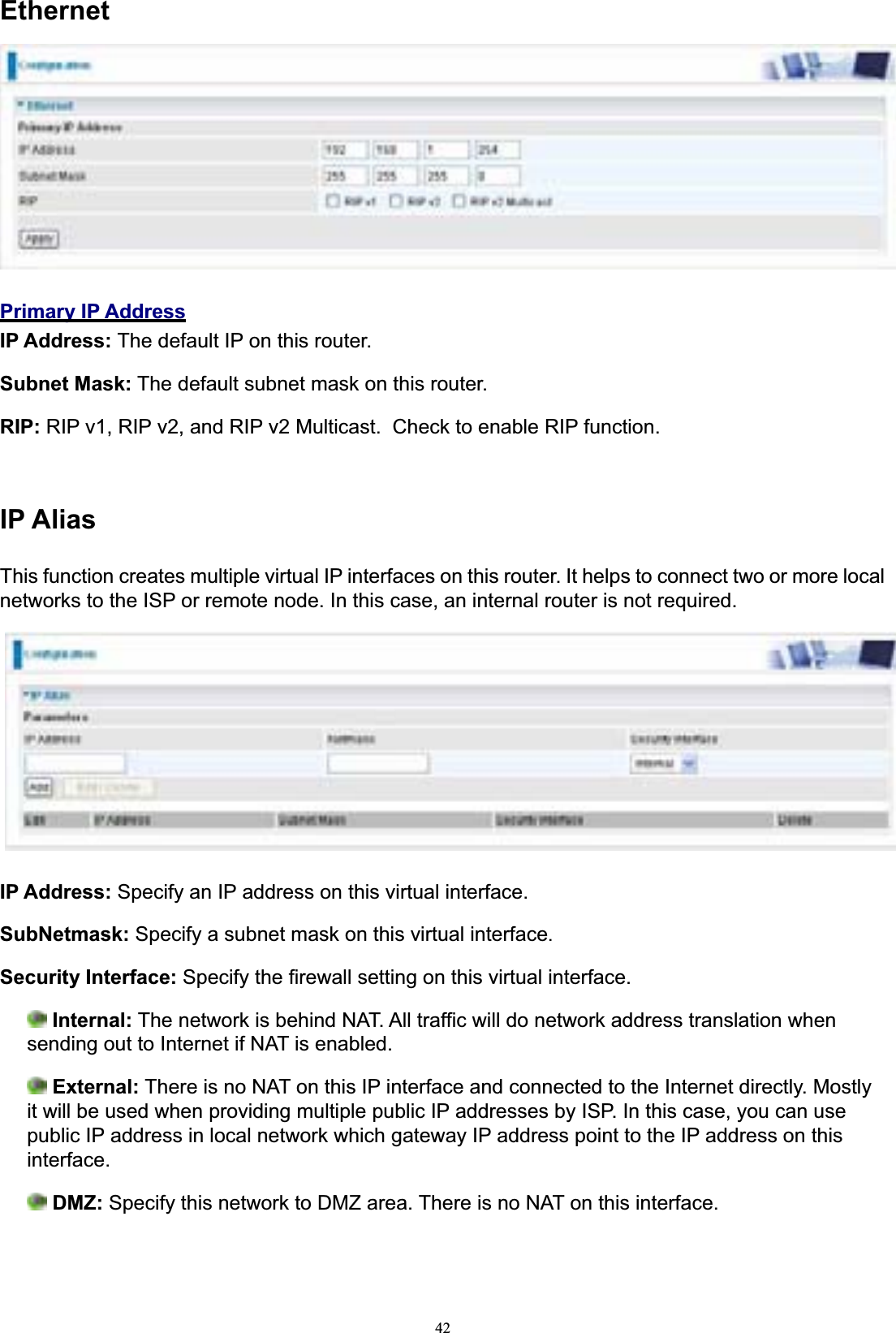
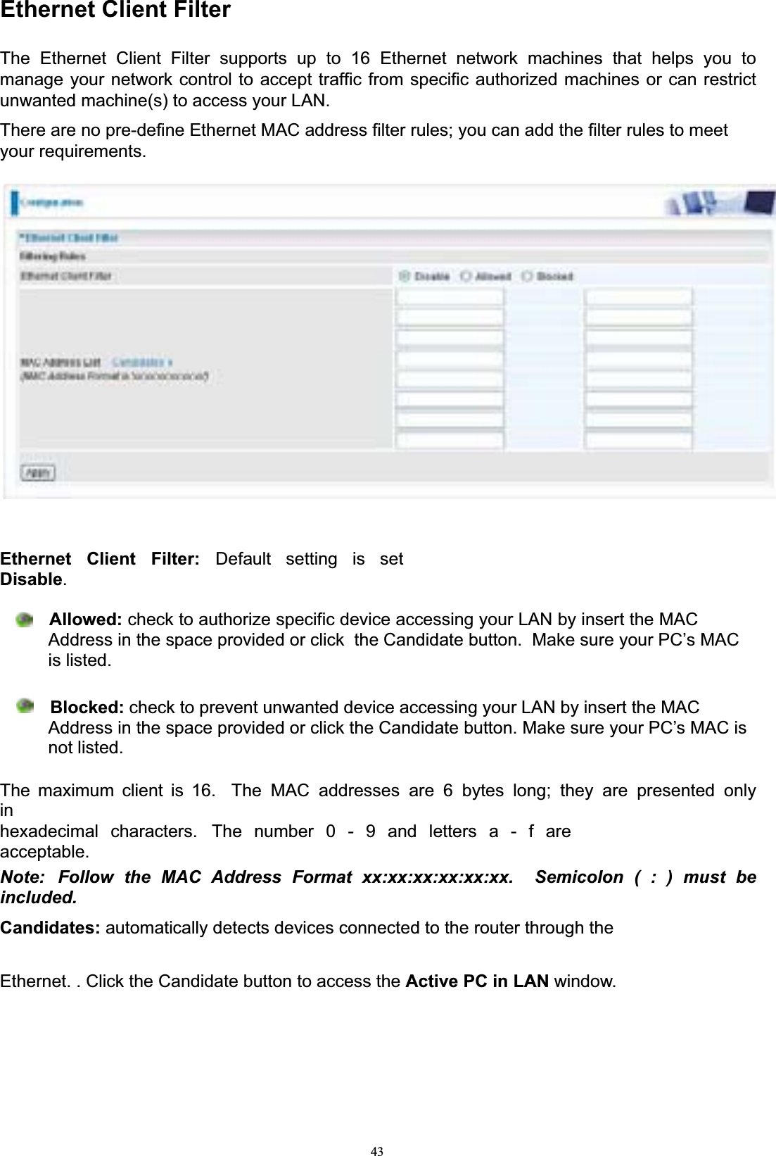
User Manual
Discussion / Help
Navigation

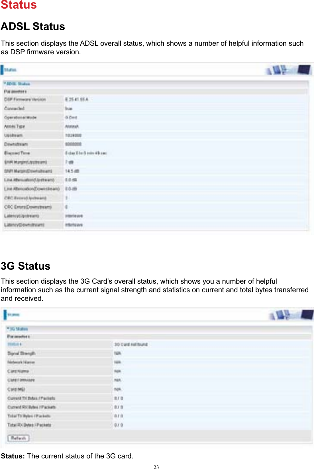
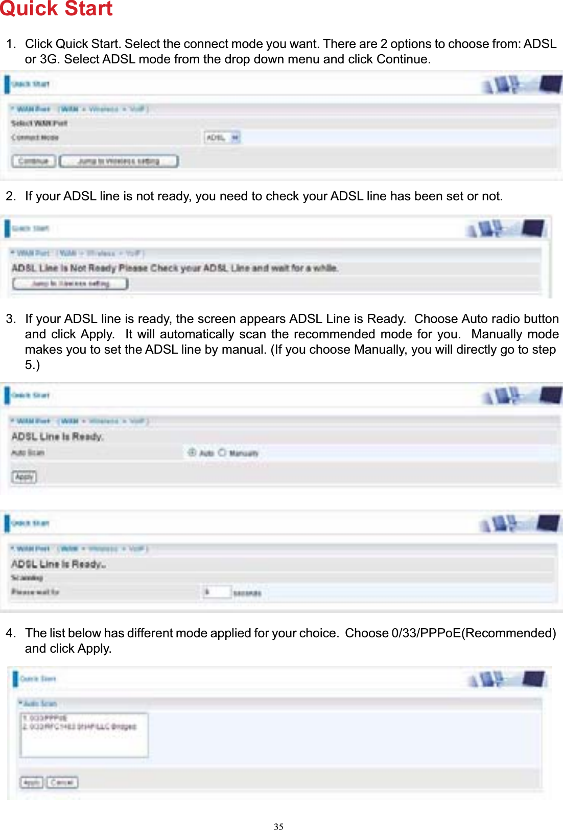
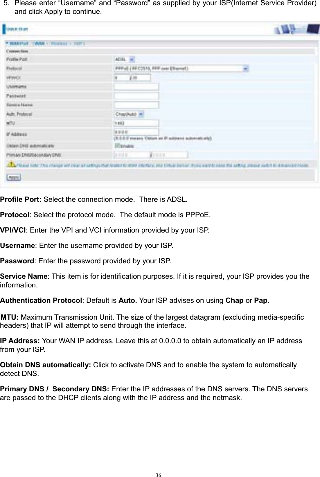
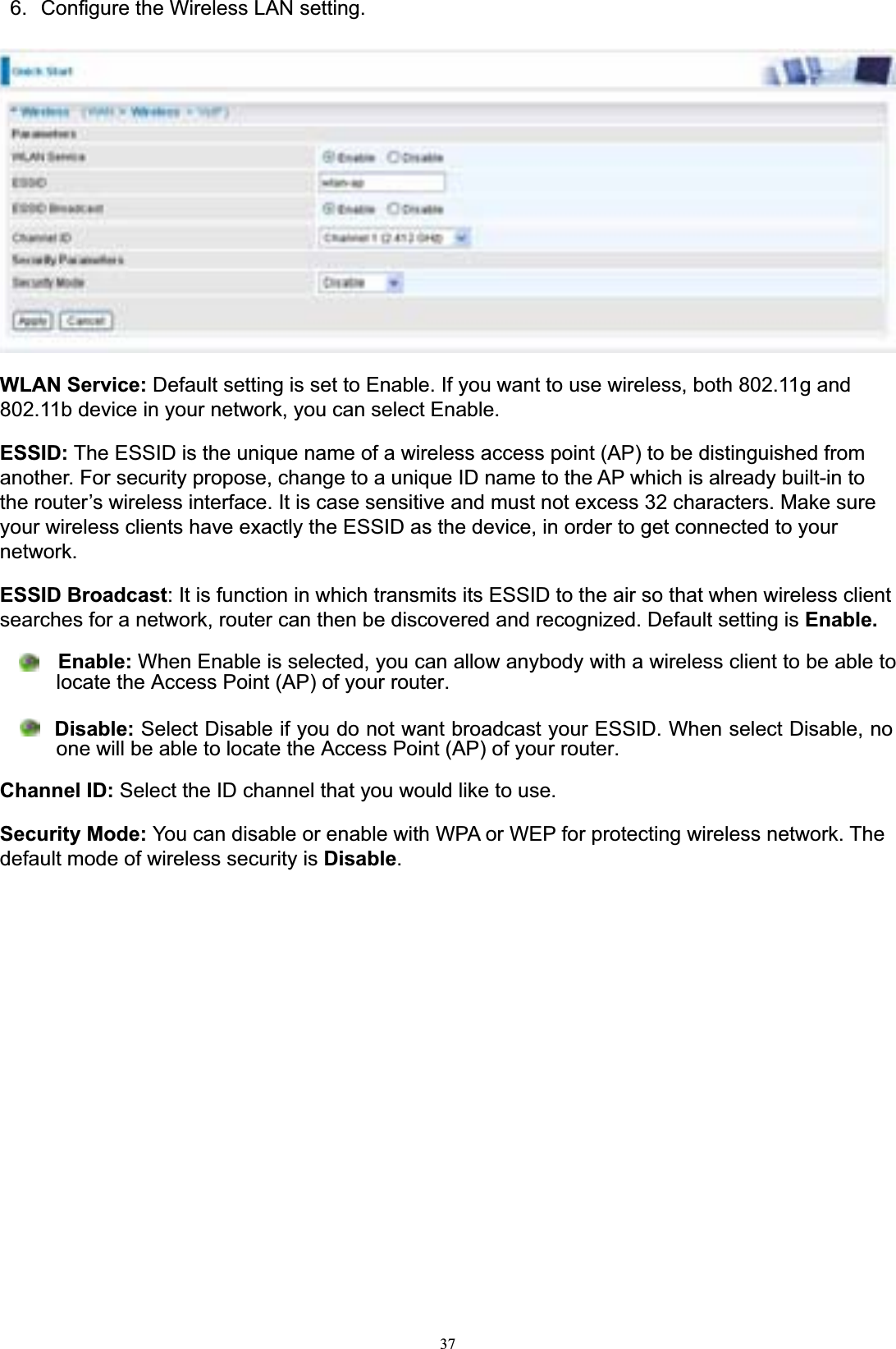
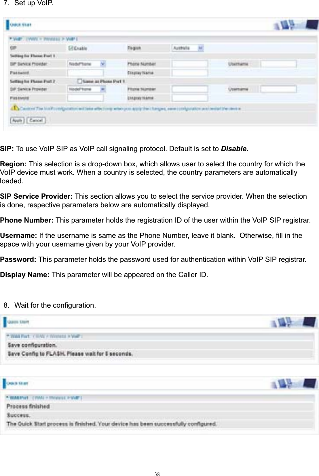


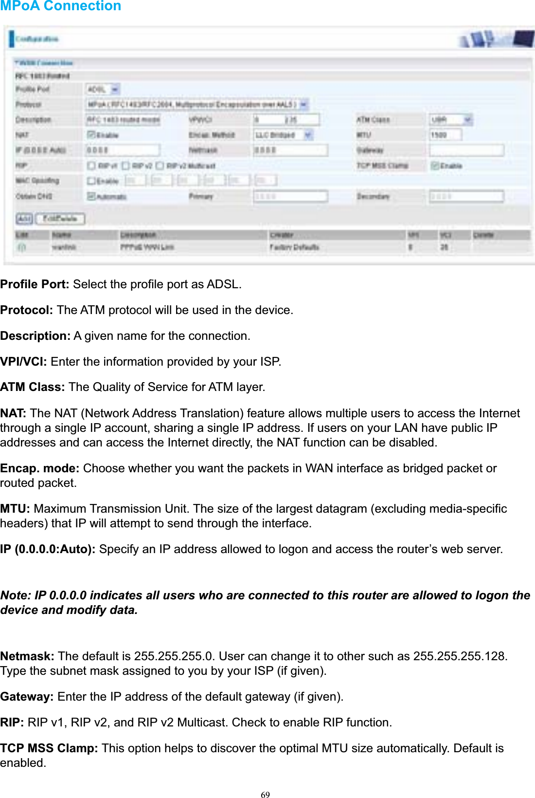
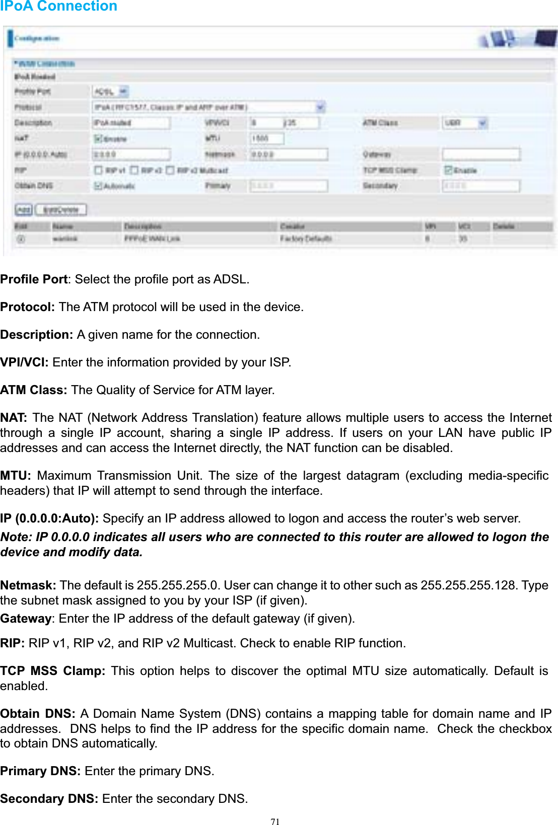
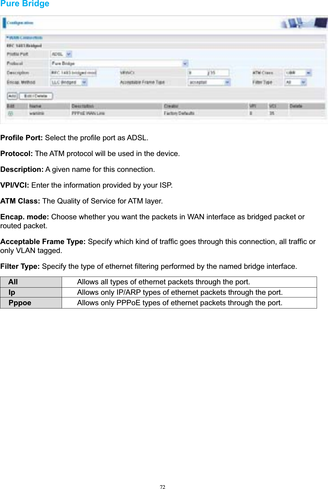
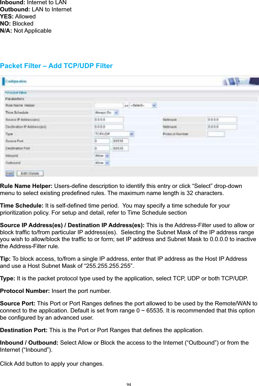
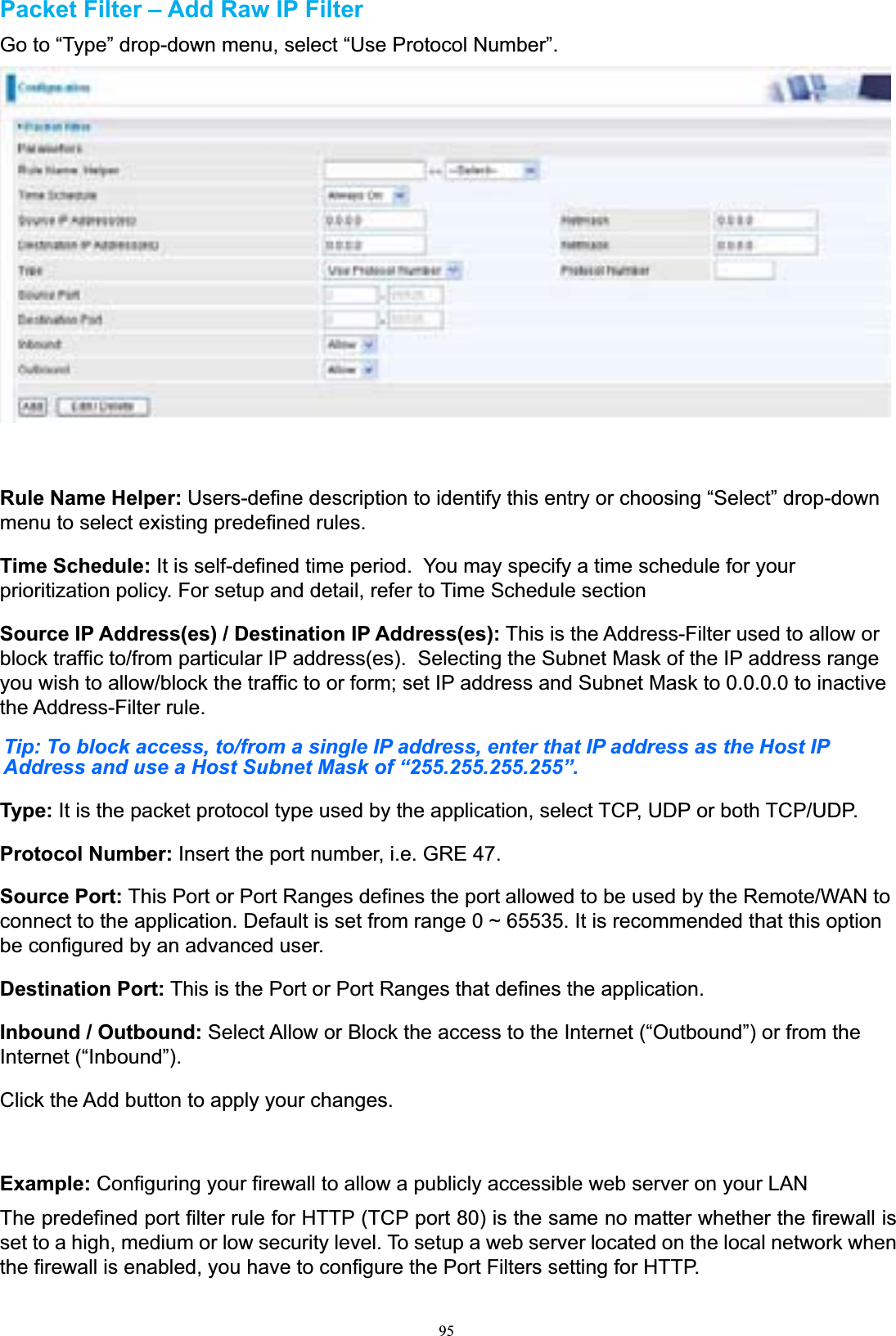

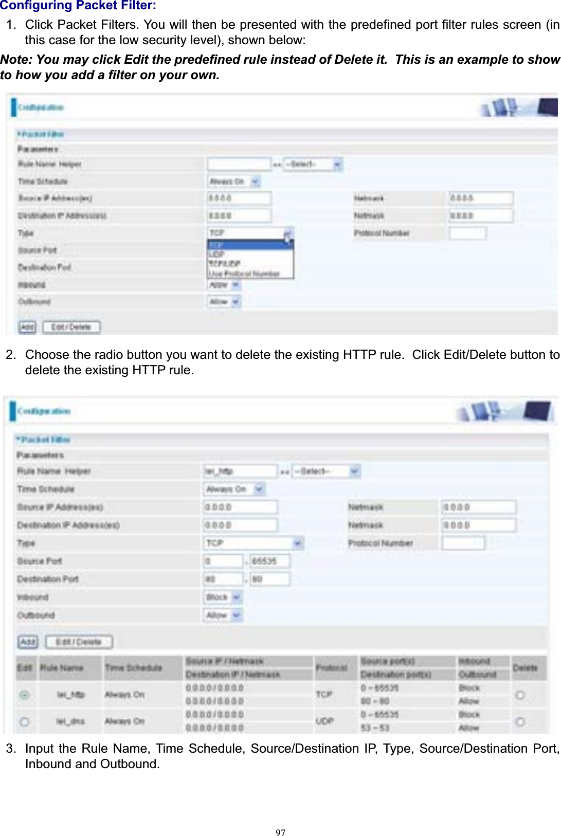
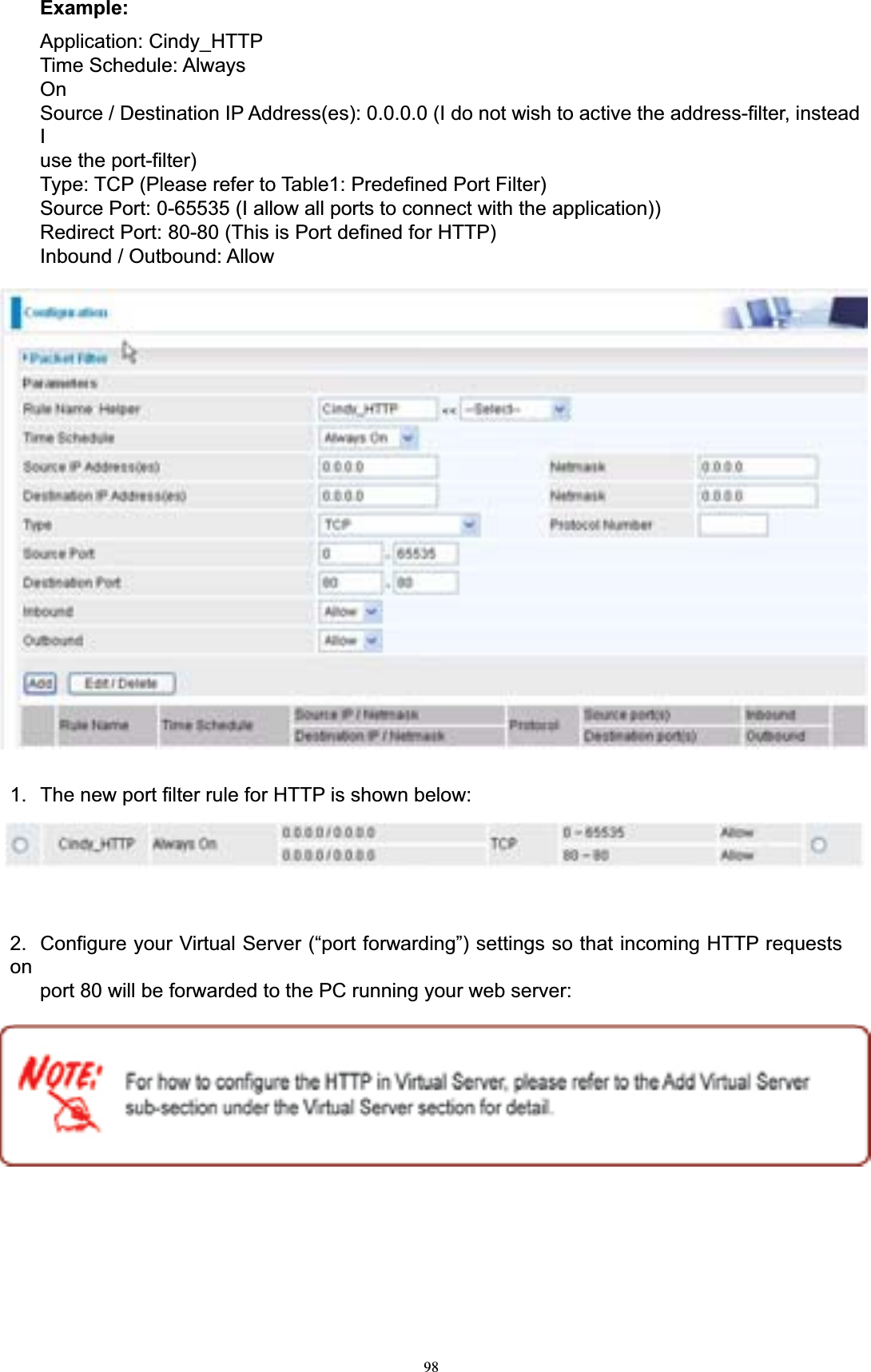

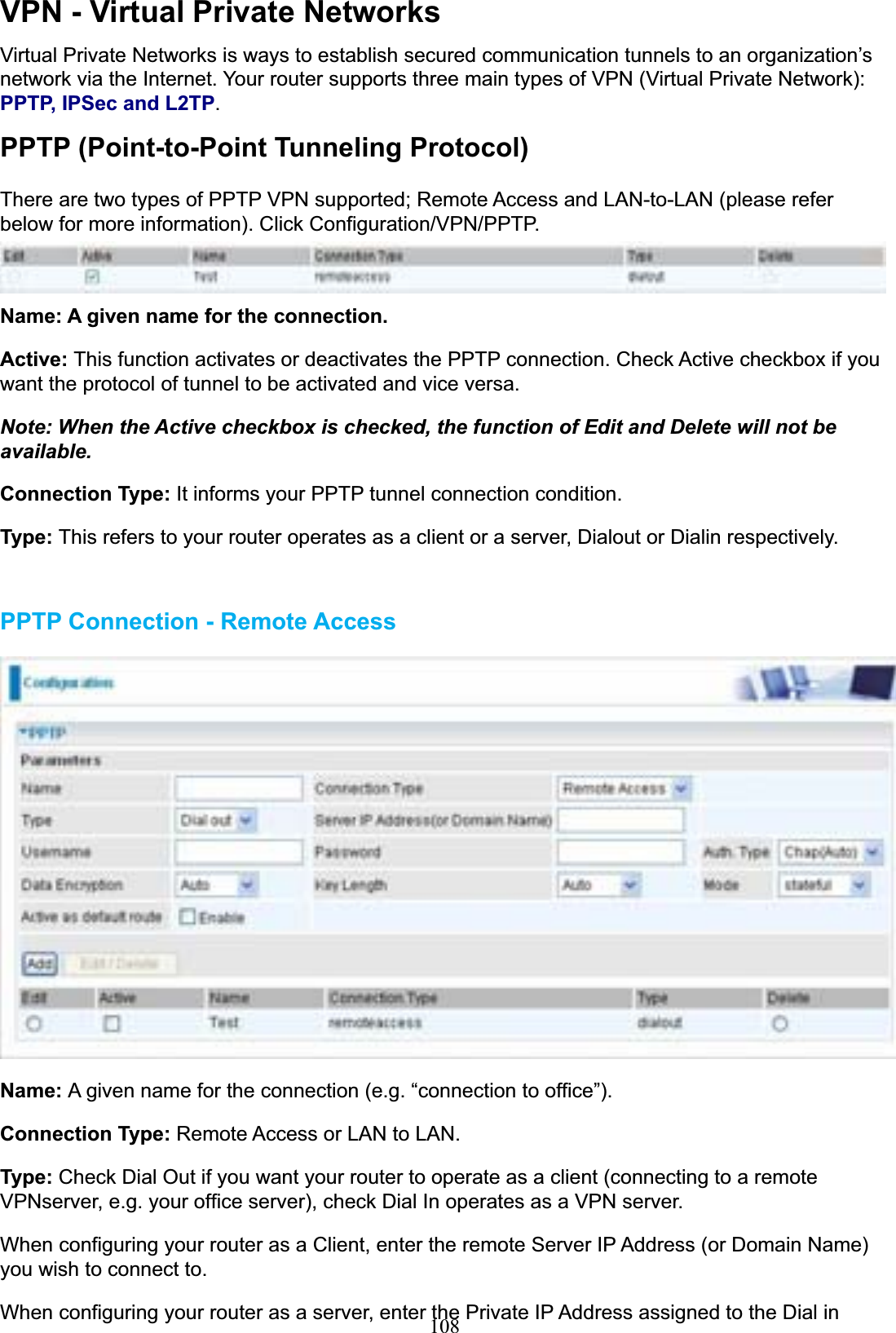
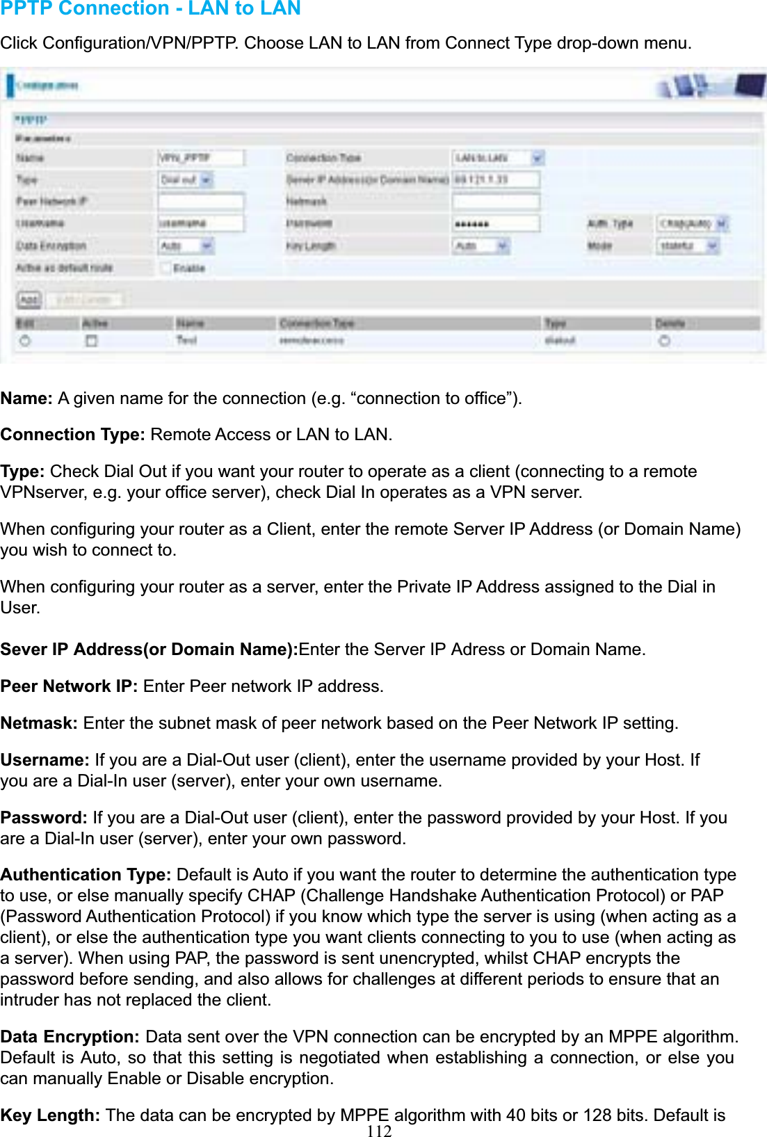
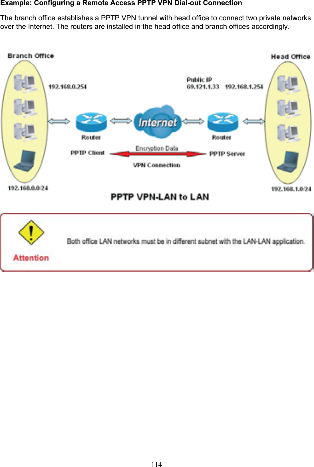
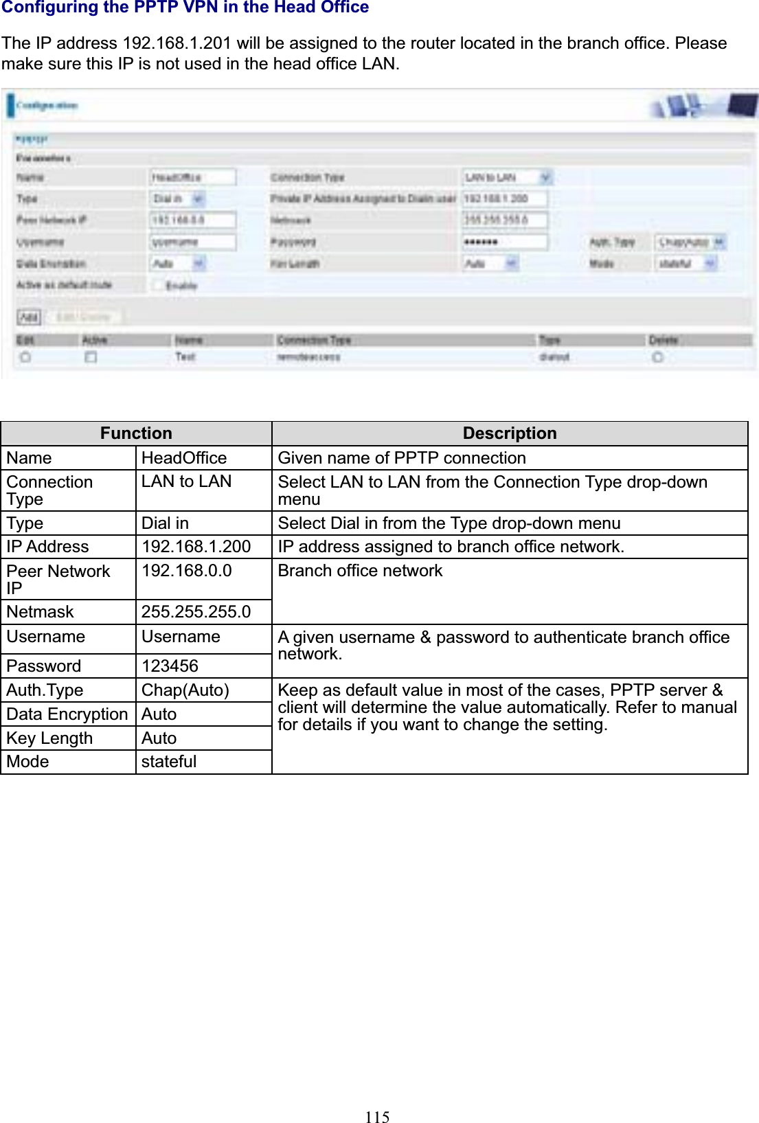


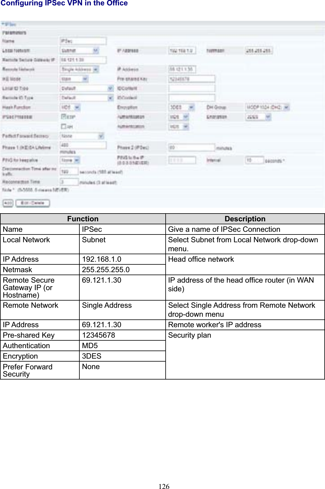
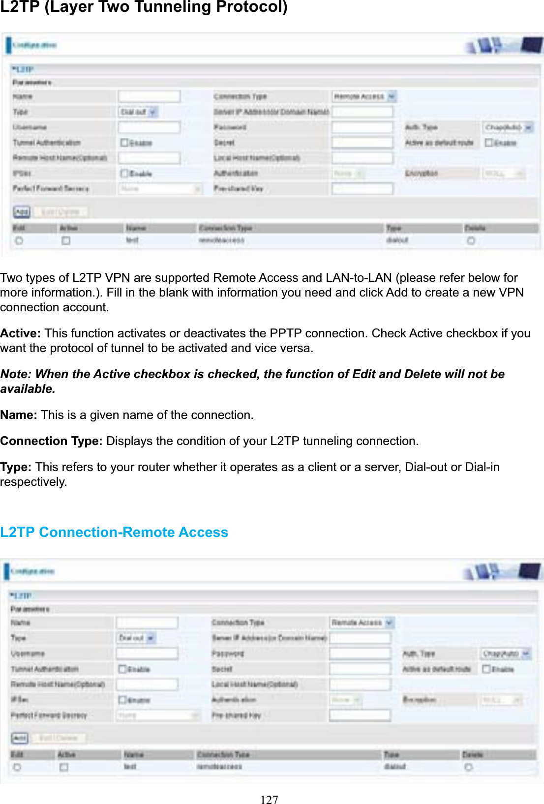
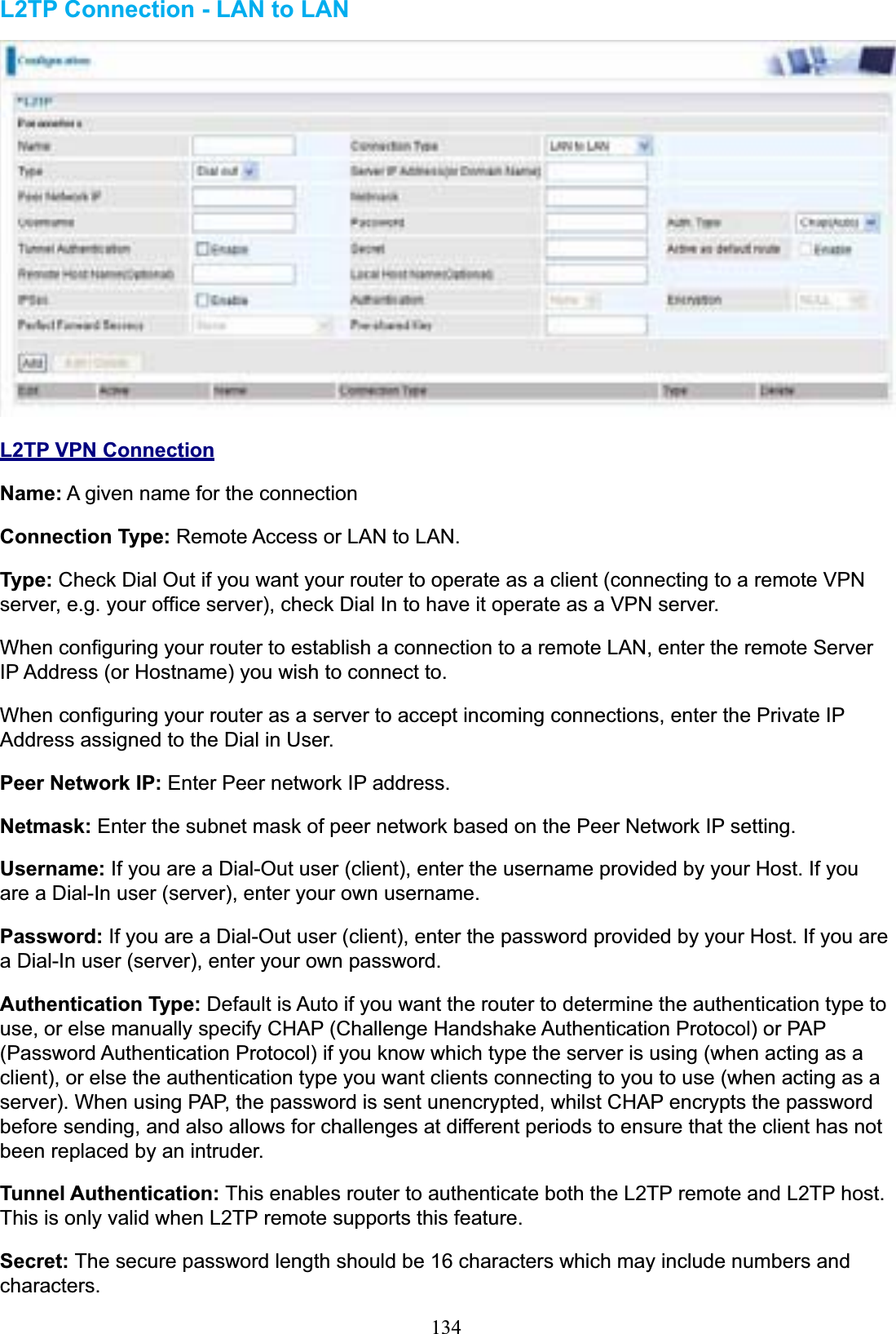

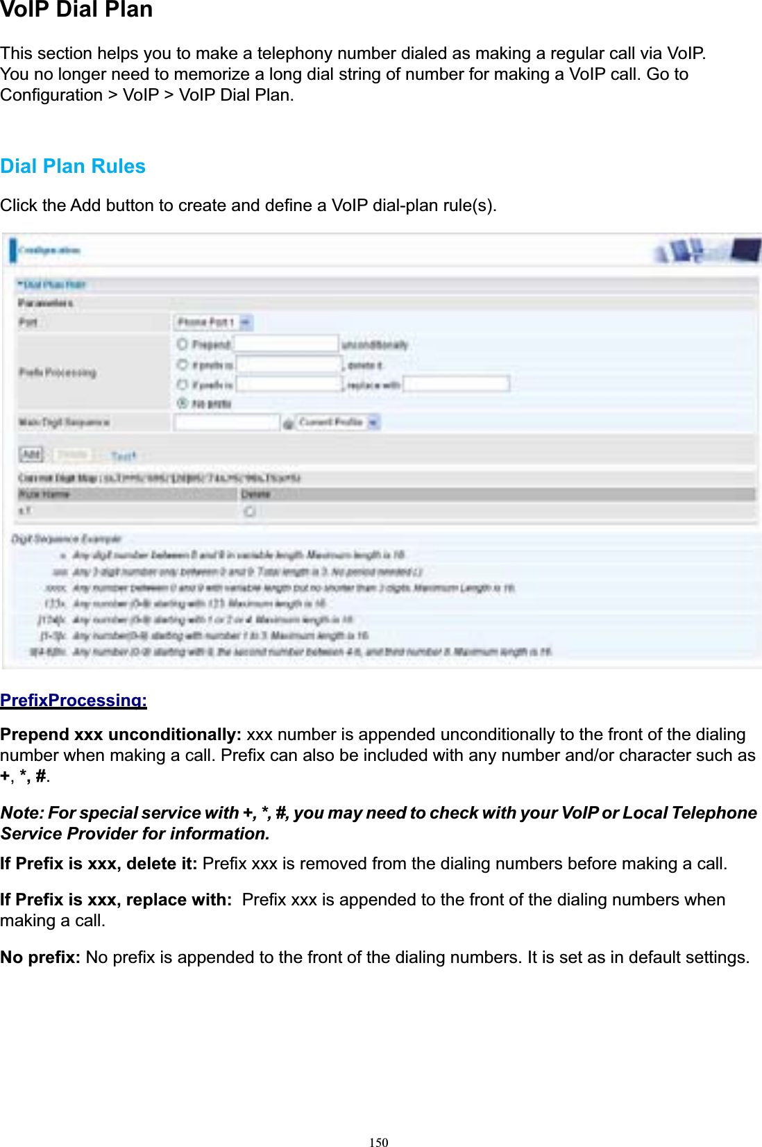
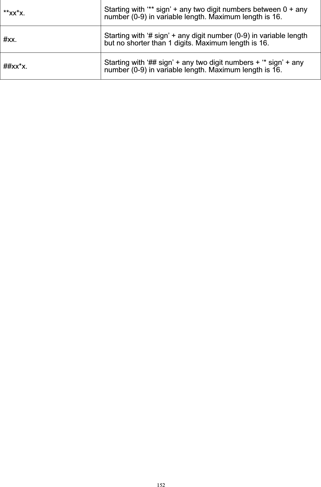
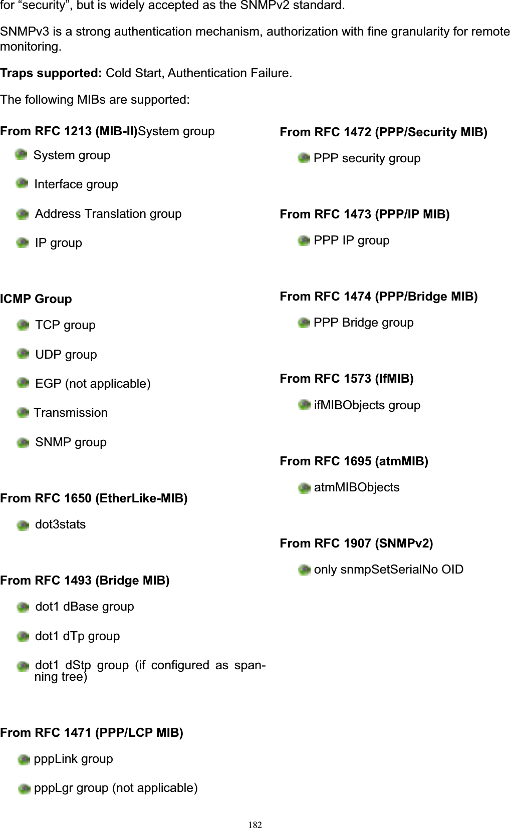
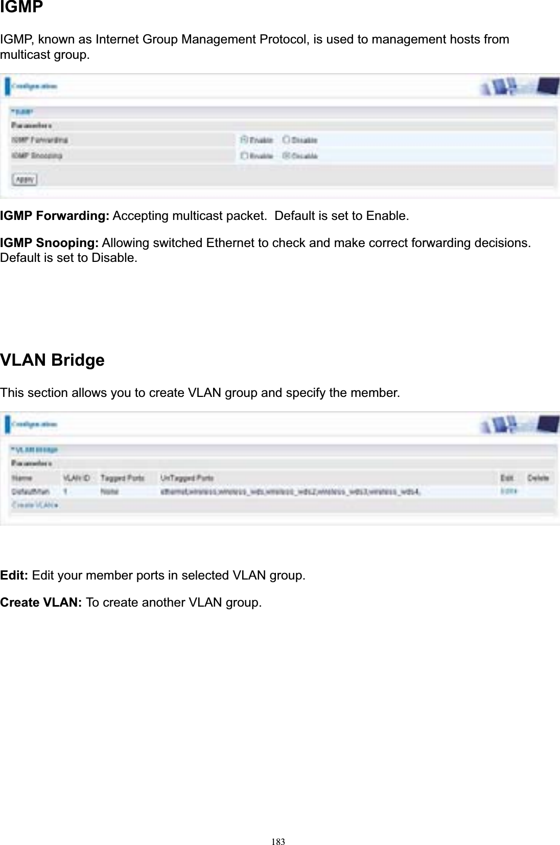
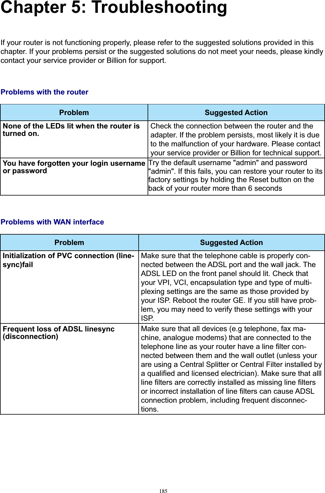
![151Main Digit Sequence: The call(s) can be called out via SIP or PSTN or ENUM. x: Any numeric number between 0 and 9. . ( period ): Repeat numeric number(s) between 0 and 9. * (asterisk sign): It is normal character ‘*’ on phone key pad. Please check if special service(s) is provided by your VoIP Service Provider or your Local Telephone Service Provider. # (pound sign): It is normal character ‘#’ on phone key pad. Please check if it is provided by your VoIP Service Provider or Local Telephone Service Provider for special service(s). <@ Current Profile>: Referring to the VoIP account registered on the VoIP Wizard for Port 1 / 2. <@ PSTN>: Meaning making call(s) via the PSTN line. <@ENUM>: Meaning making a VoIP SIP direct call via E.164 number (“ENUM”) to an ENUM callee.Electronic Number (ENUM) uses the DNS (Domain Network System) based technology to map between a traditional phone number (PSTN) to an Internet addresses/ SIP URL. The ENUM number must be registered via a public ENUM site or your VoIP Service Provider. <@ SIPgateway>: It is used for the Intelligent Call Routing feature where you need to set up your SIP account on the VoIP User-defined Profiles link on the VoIP Wizard page. Go to the VoIP Wizard in this manual for more information. Dial-Plan Examples: Descriptionx. Any digit number between 0 and 9 in variable length. Maximumlength is 16.xxx Any 3 digit number only between 0 and 9. Total length is 3. Note: No period is needed (.)xxxx. Any number between 0 and 9 with variable length but no shorterthan 3 digits. Maximum length is 16.123x. Any number (0-9) starting with 123. Maximum length is 16.[x…x]x. For example: [124]x.Any number (0-9) starting with 1 or 2 or 4. Maximum length is16.[x-x]x. For example: [1-3]x.Any number (0-9) starting with number 1 to 3. Maximum length is16.x[x-x]x. For example: 9[4-6]8x.Any number (0-9) starting with 9, the second number between4-6, and third number 8. Maximum length is 16.Special Dial PlanExamples: Description*xx*x. Starting with ‘* sign’ + any two digit numbers + any number (0-9)in variable length. Maximum length is 16.*xxStarting with ‘* sign’ + any 2 digit numbers between 0 and 9. Totallength including the * is 3. Note: No period is needed (.)](https://usermanual.wiki/Billion-Electric/BIL-7404VGOXC/User-Guide-1270915-Page-154.png)