Billion Electric BIL-7820NZ Slots ADSL2+ Wireless-N VPN Firewall Router User Manual Users manual 1
Billion Electric Co., Ltd. Slots ADSL2+ Wireless-N VPN Firewall Router Users manual 1
Contents
- 1. Users manual-1
- 2. Users manual-2
- 3. Users manual-3
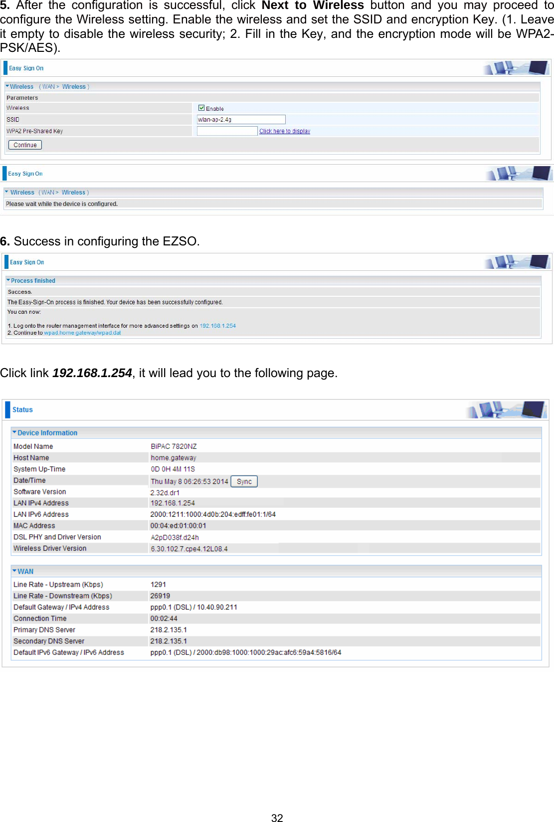
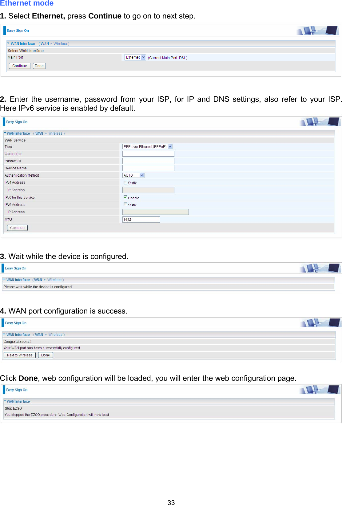
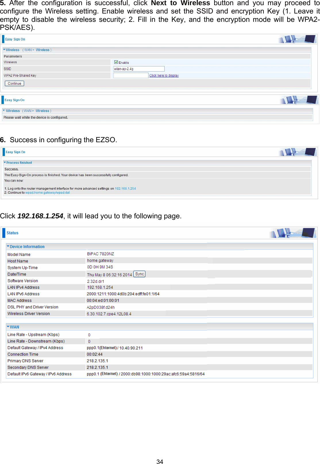
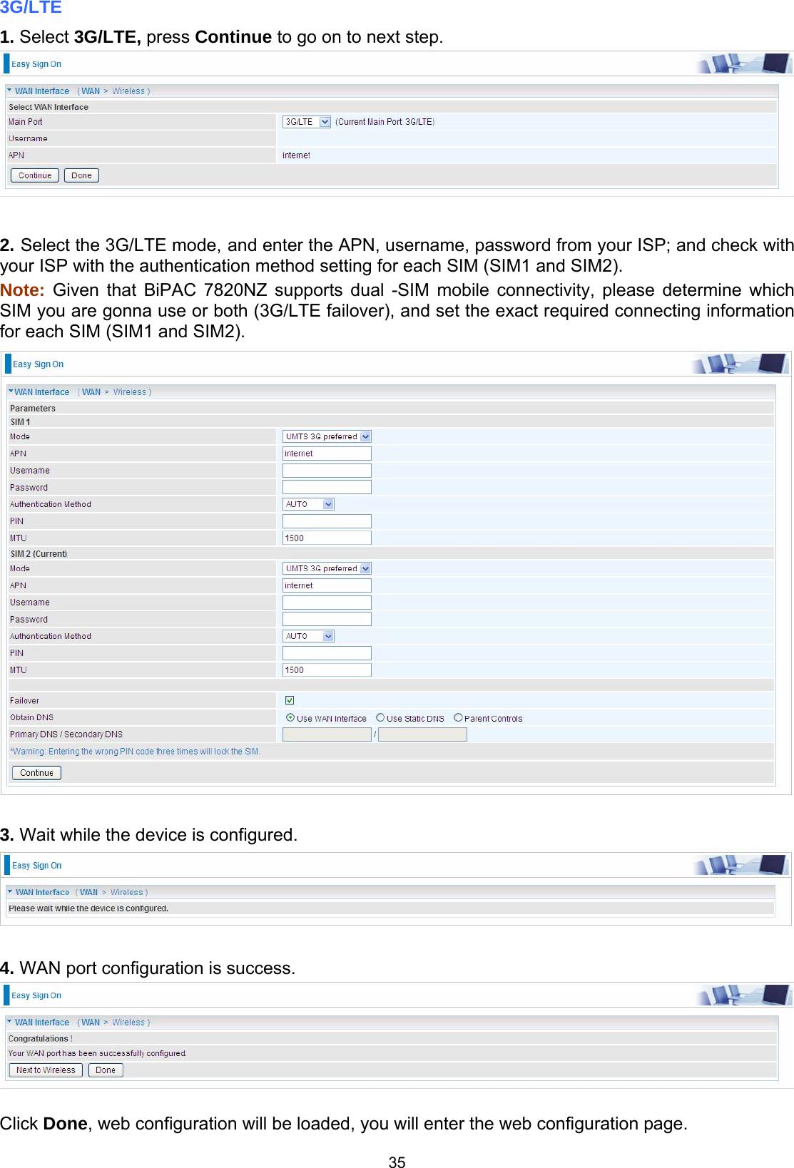
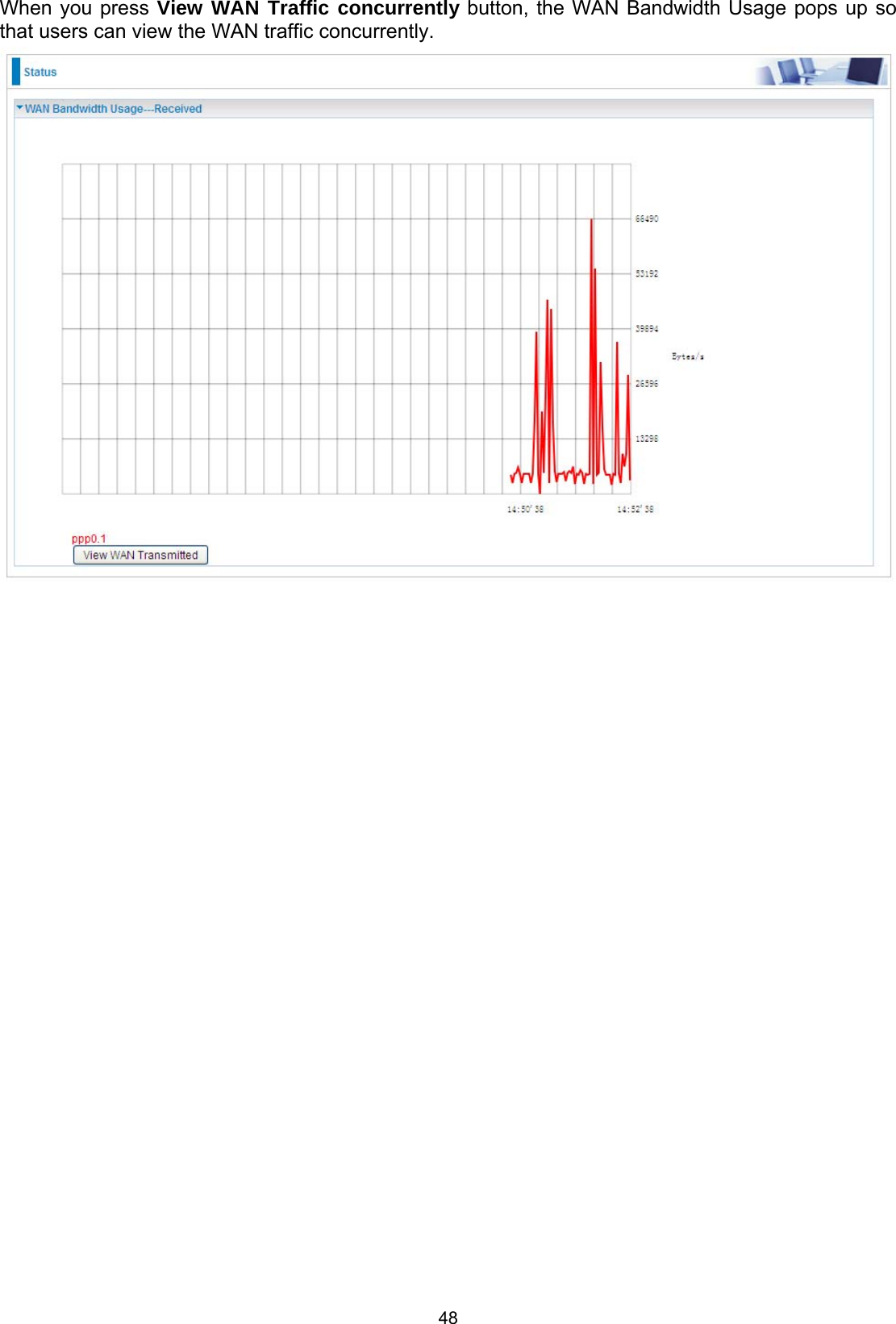
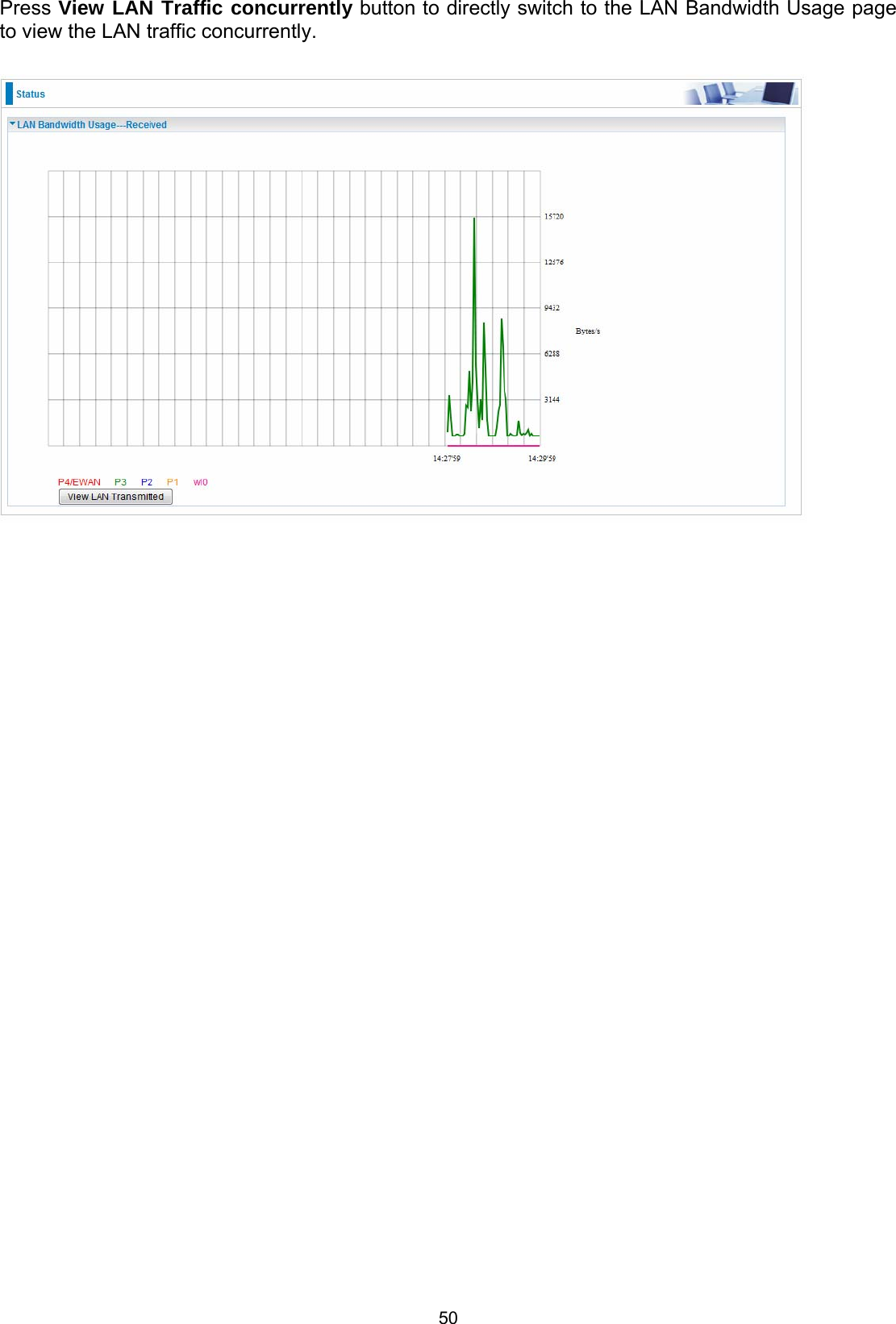
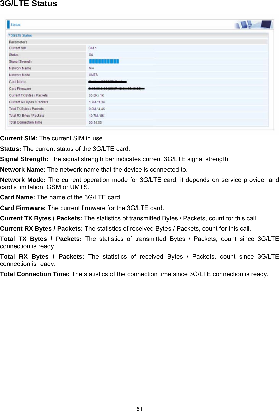
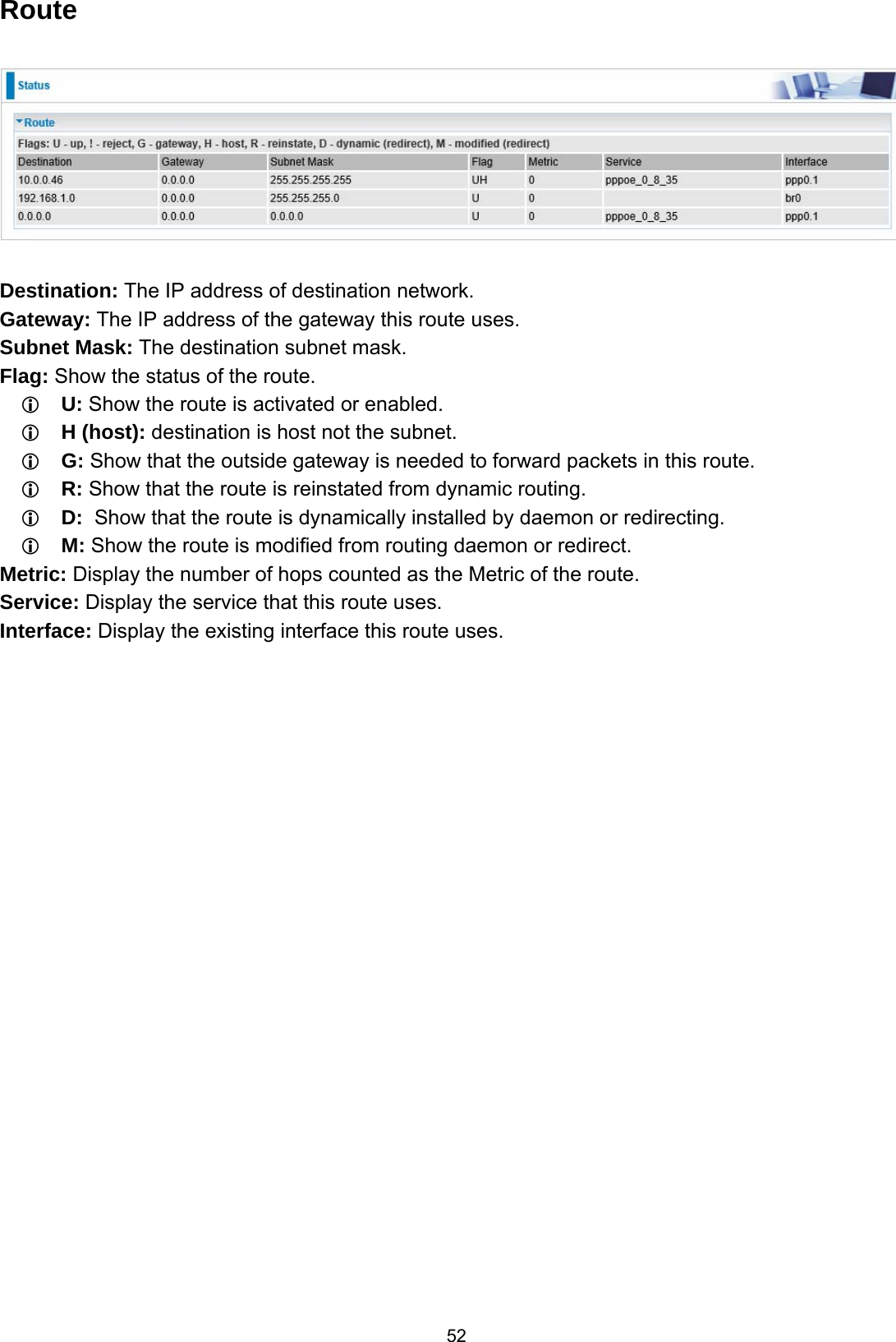
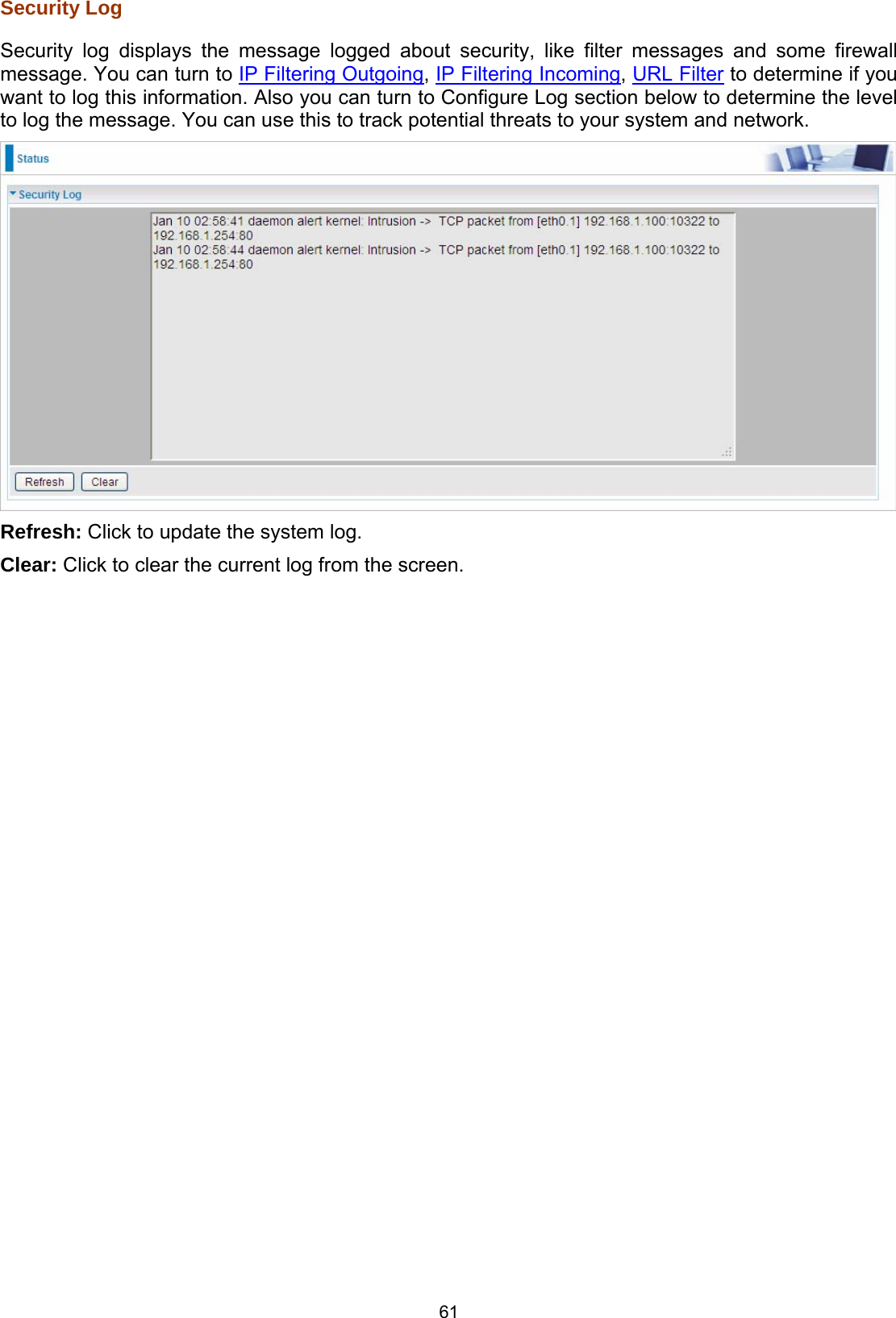
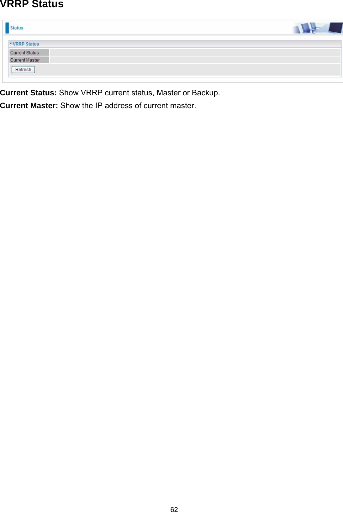
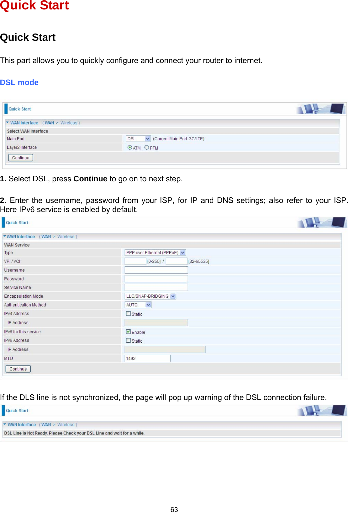
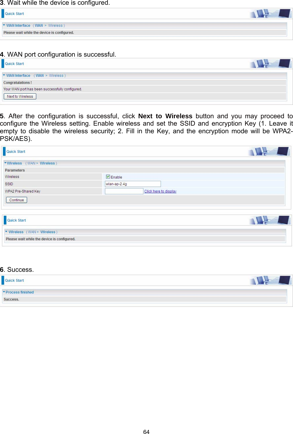
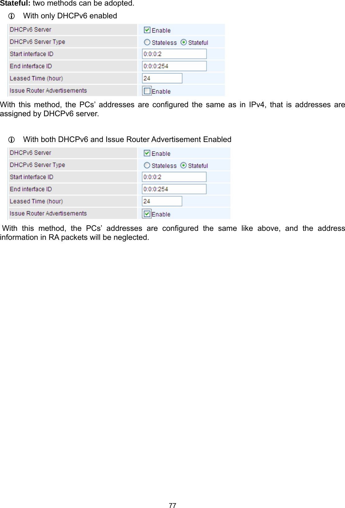
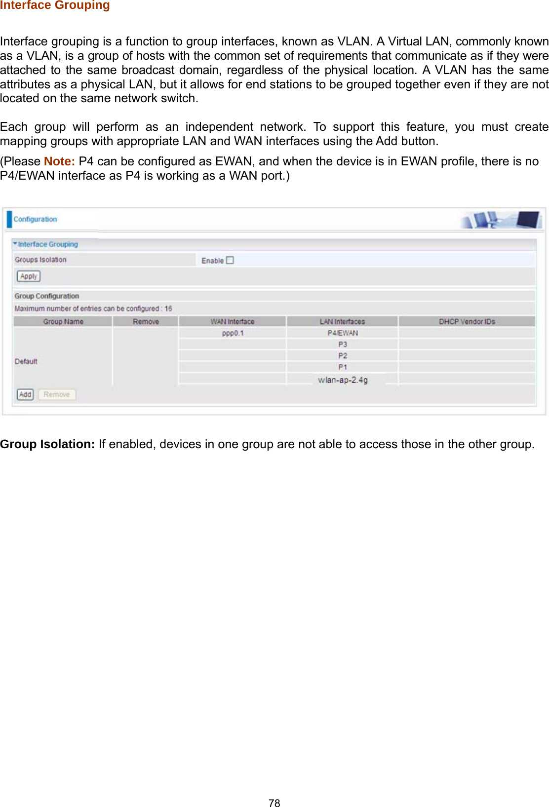
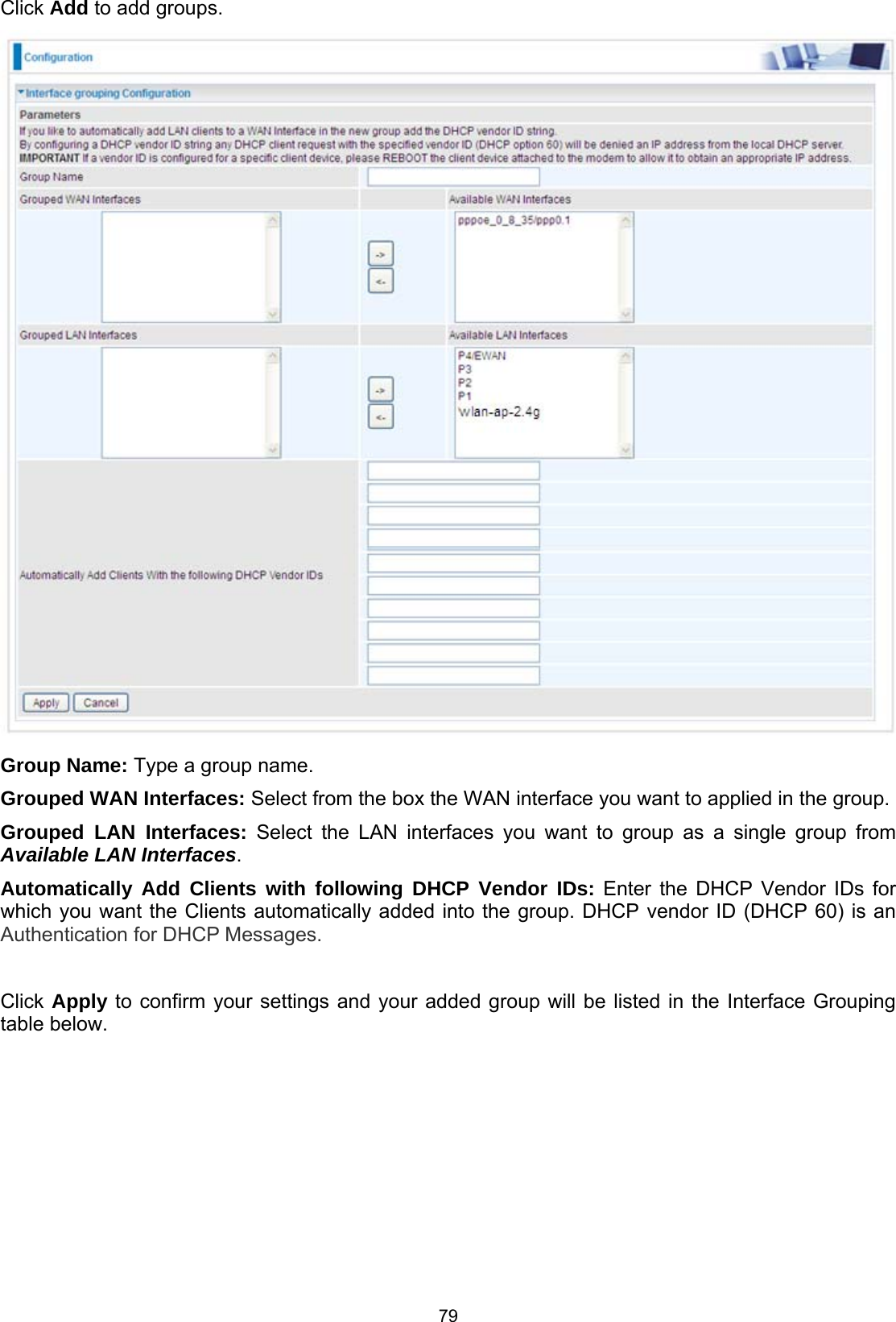
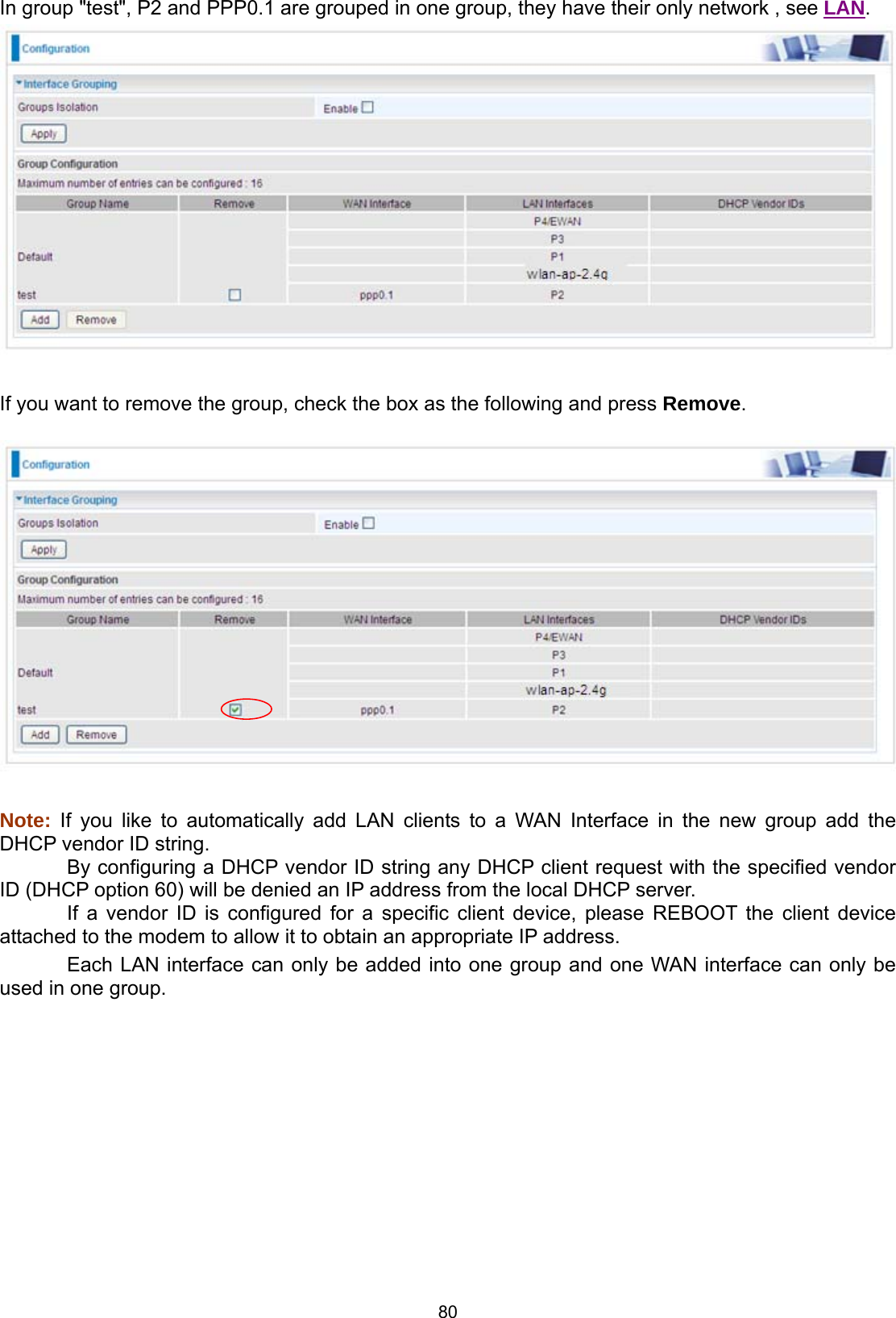
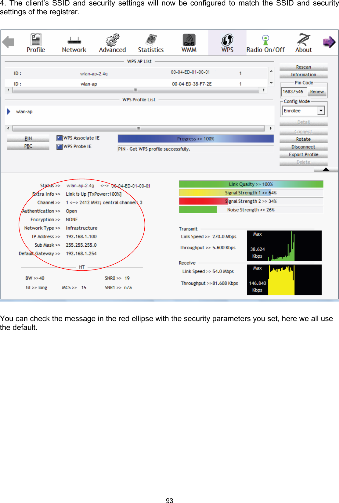
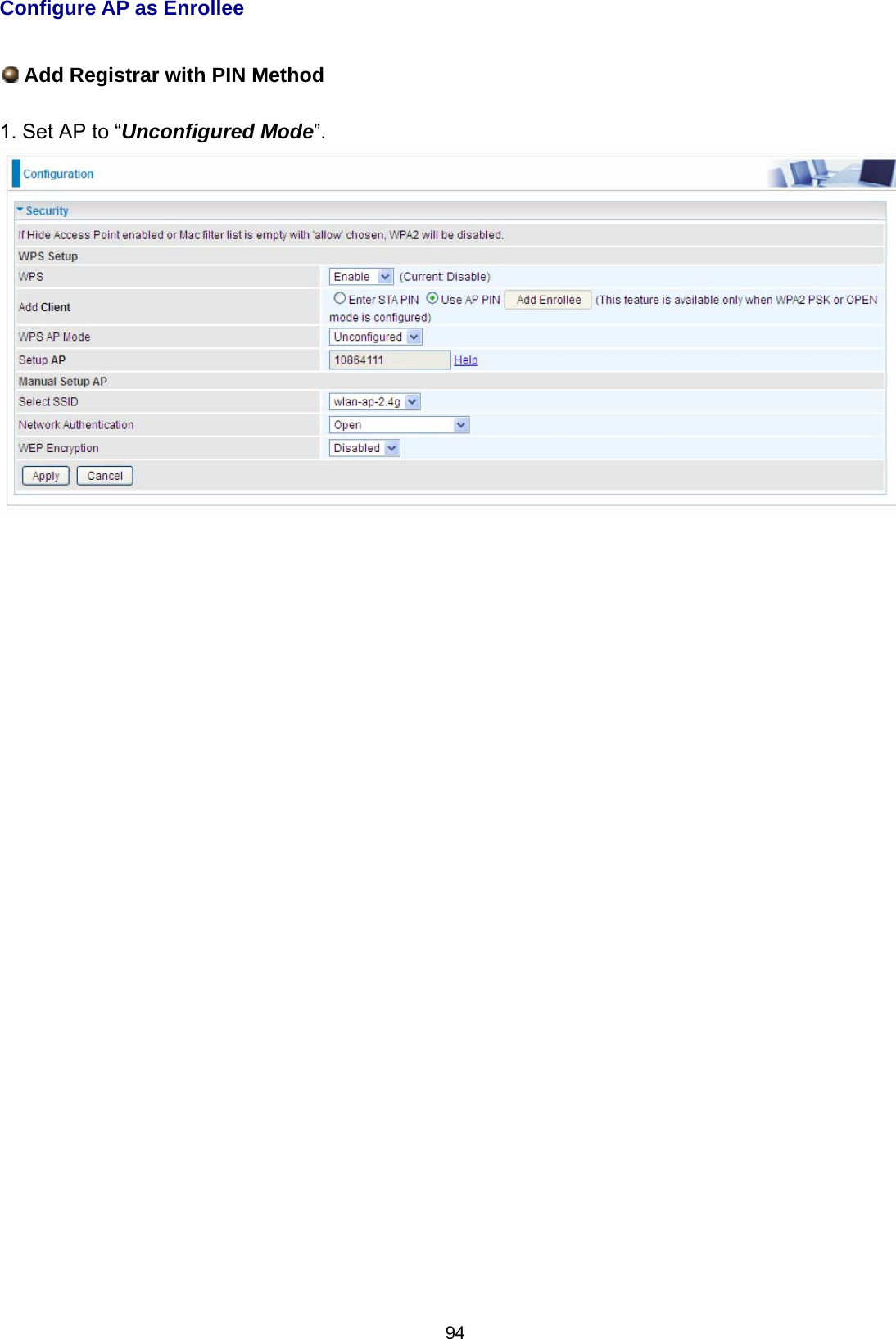
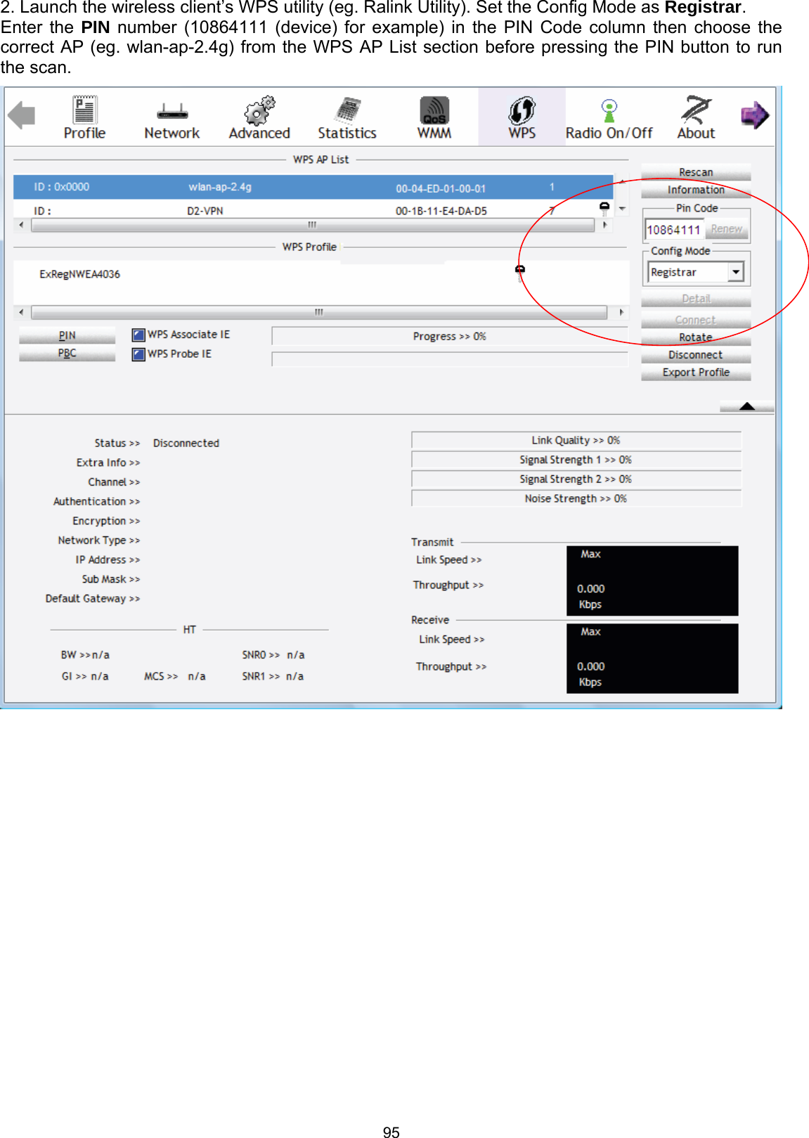
Users manual-1