Billion Electric BIL-8920AX Dual-lines VDSL2/ADSL2+ Wireless-AC 3G/4G LTE VPN Firewall Router User Manual 2
Billion Electric Co., Ltd. Dual-lines VDSL2/ADSL2+ Wireless-AC 3G/4G LTE VPN Firewall Router Users Manual 2
Contents
- 1. Users Manual-2
- 2. Users Manual-3
- 3. Users Manual-1-revised 0902
Users Manual-2
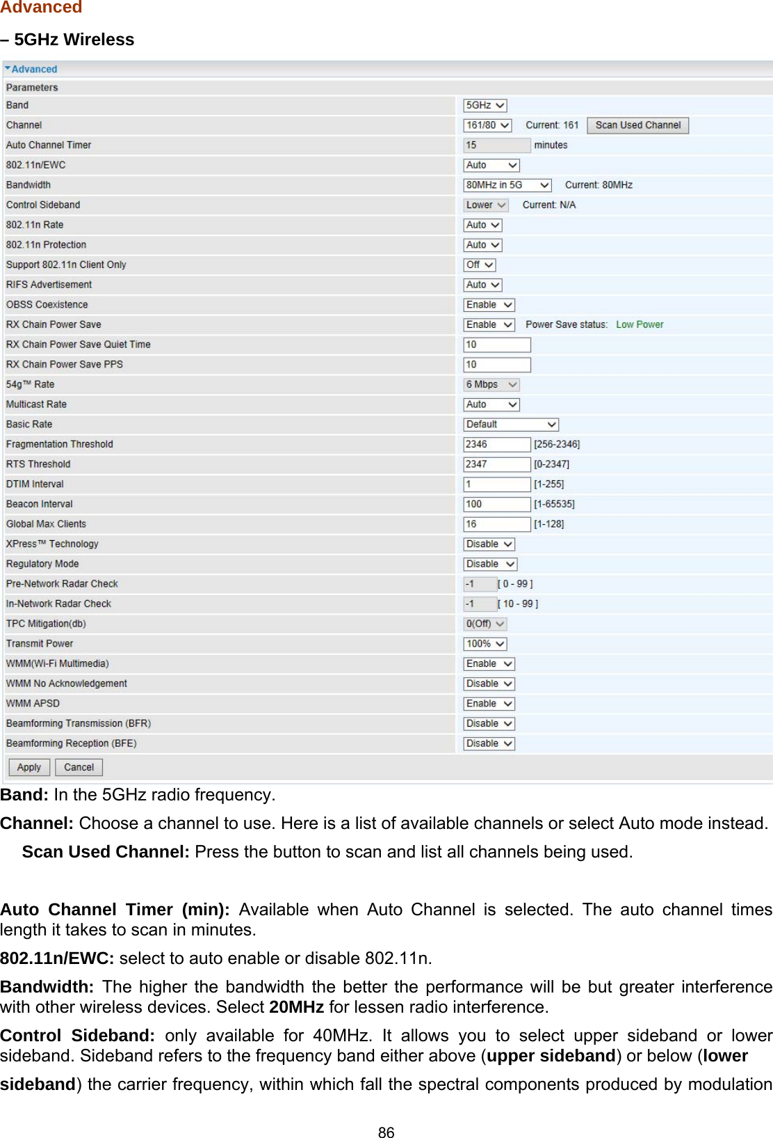
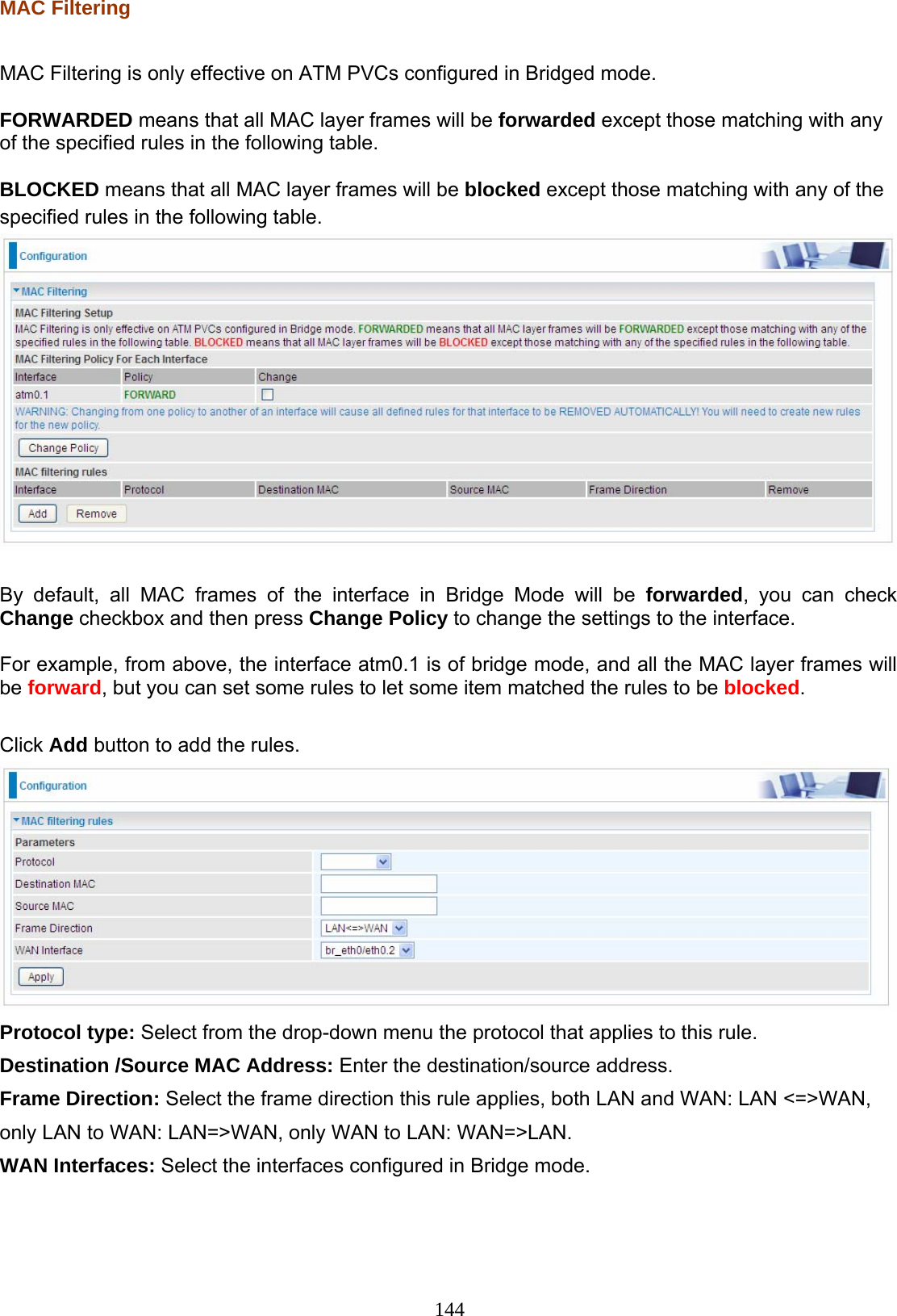
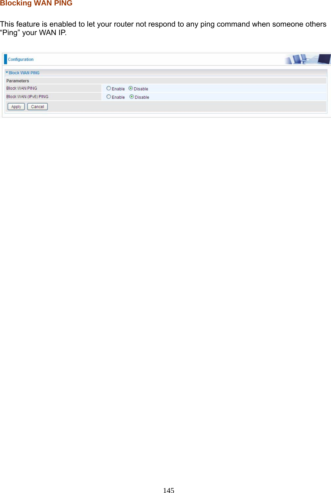
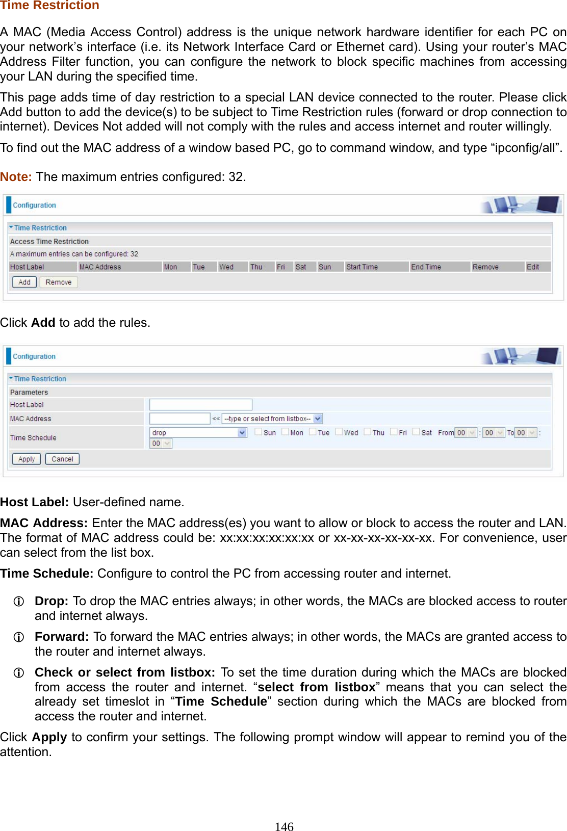
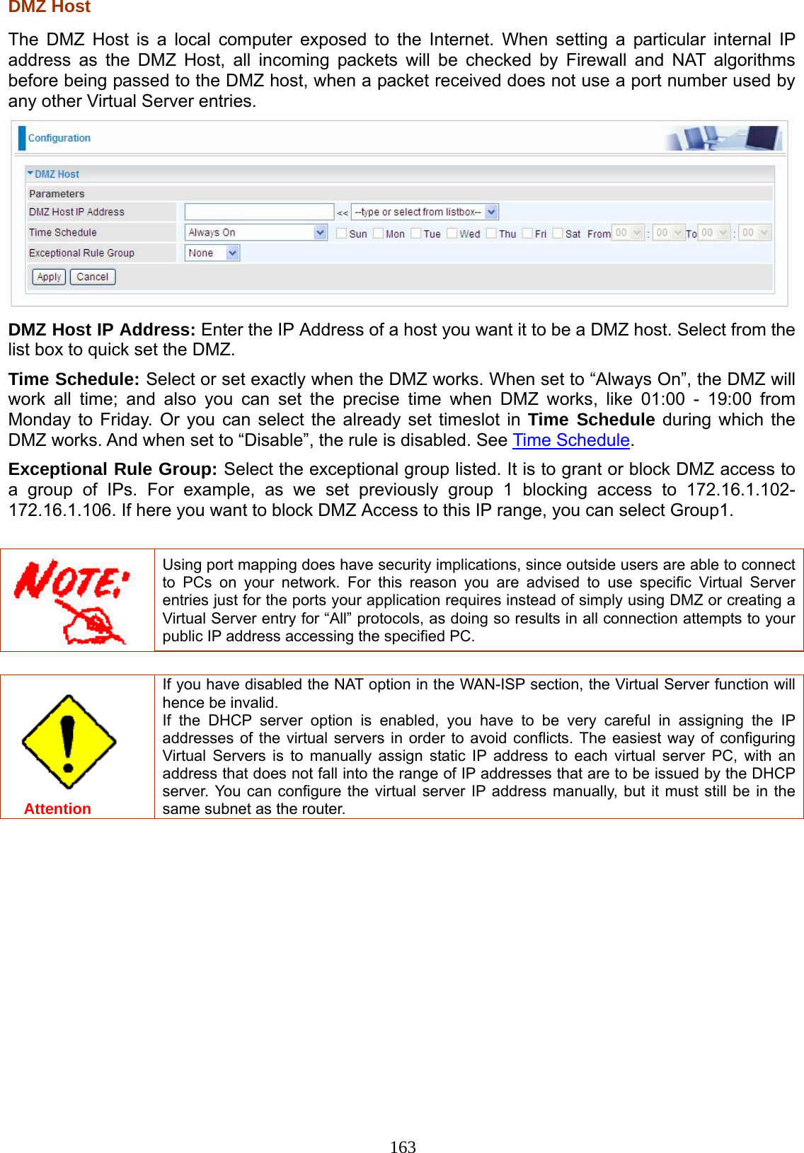
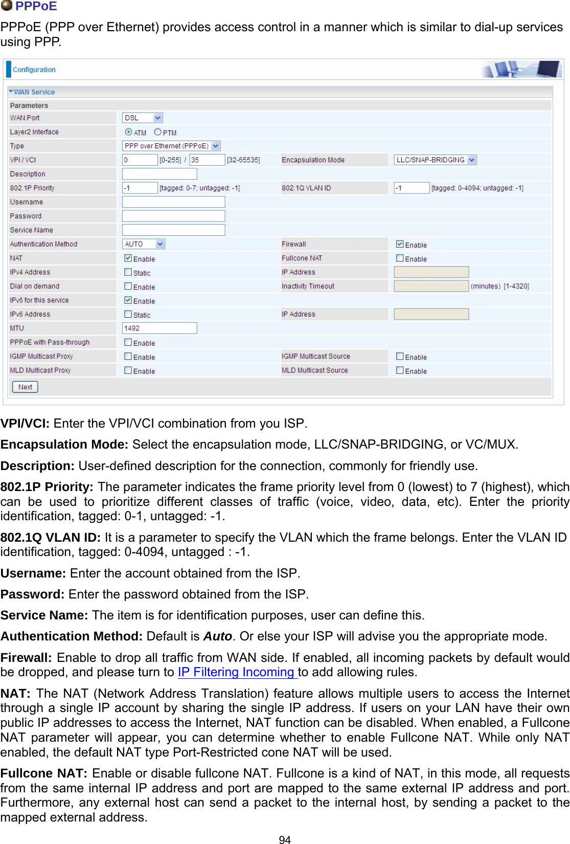
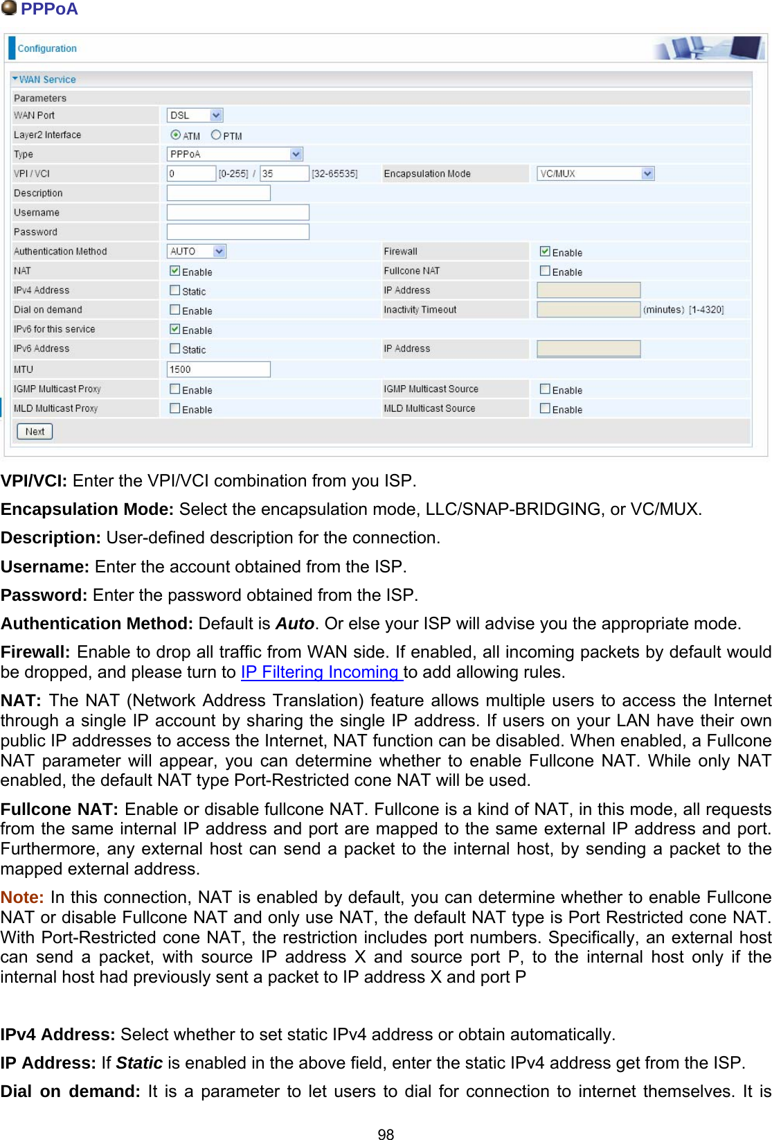
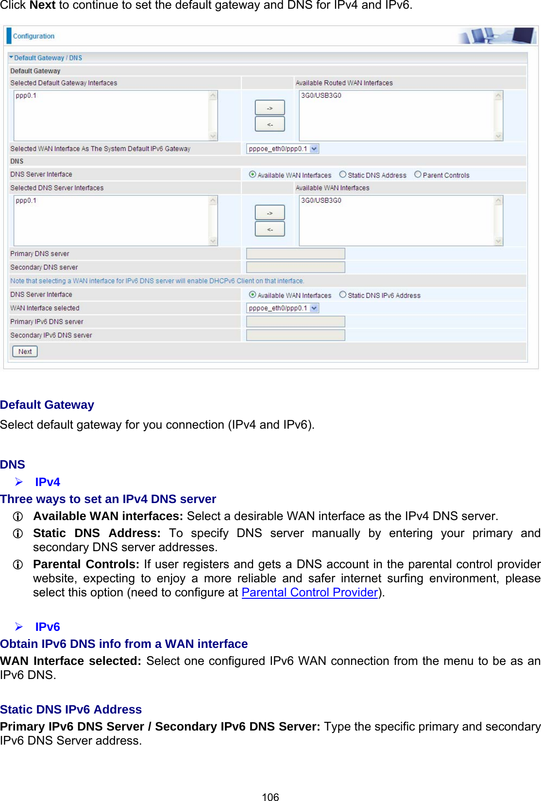
![88 Pre-Network Radar Check (Used for 802.11h only): Specifies a period of time in seconds [0-99] to check for radar on a channel before the Access Point establishes a wireless network with the channel. In-Network Radar Check (Used for 802.11h only): After the wireless network got established, specifies a period of time in seconds [10-99] to check for radar when switching to another non-radar channel. TPC Mitigation (db): Known as Transmitter Power Control mitigation to reduce unnecessary transmitting power radio and possible radio interference to other users. Transmit Power: select the transmitting power of your wireless signal. WMM (Wi-Fi Multimedia): you can choose to enable or disable this function which allows for priority of certain data over wireless network. WMM No Acknowledgement: Refers to the acknowledge policy at the MAC level. Enabling WMM No Acknowledgement can result in more efficient throughput but higher error rates in noisy Radio Frequency (RF) environment. WMM APSD: Automatic Power Save Delivery. Enable this to save power. Beamforming Transmission (BFR) / Beamforming Reception (BFE): Enable to increase wireless speed by focusing and concentrating transmitted (send) and/or receive signals with a wireless client instead of broadcast signals in all directions. Note: Both router and client wireless must support beamforming technology.](https://usermanual.wiki/Billion-Electric/BIL-8920AX.Users-Manual-2/User-Guide-2734658-Page-5.png)
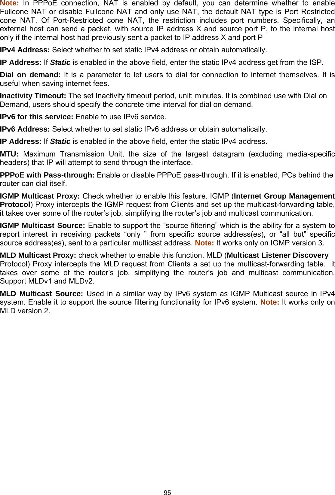
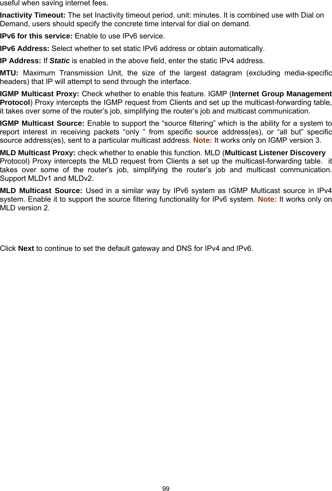
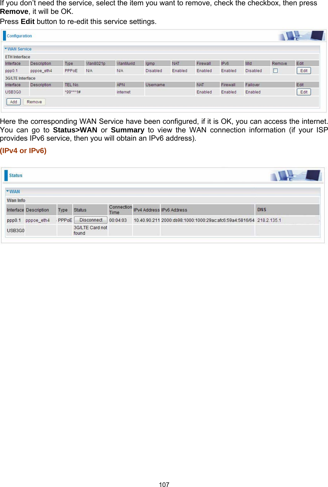

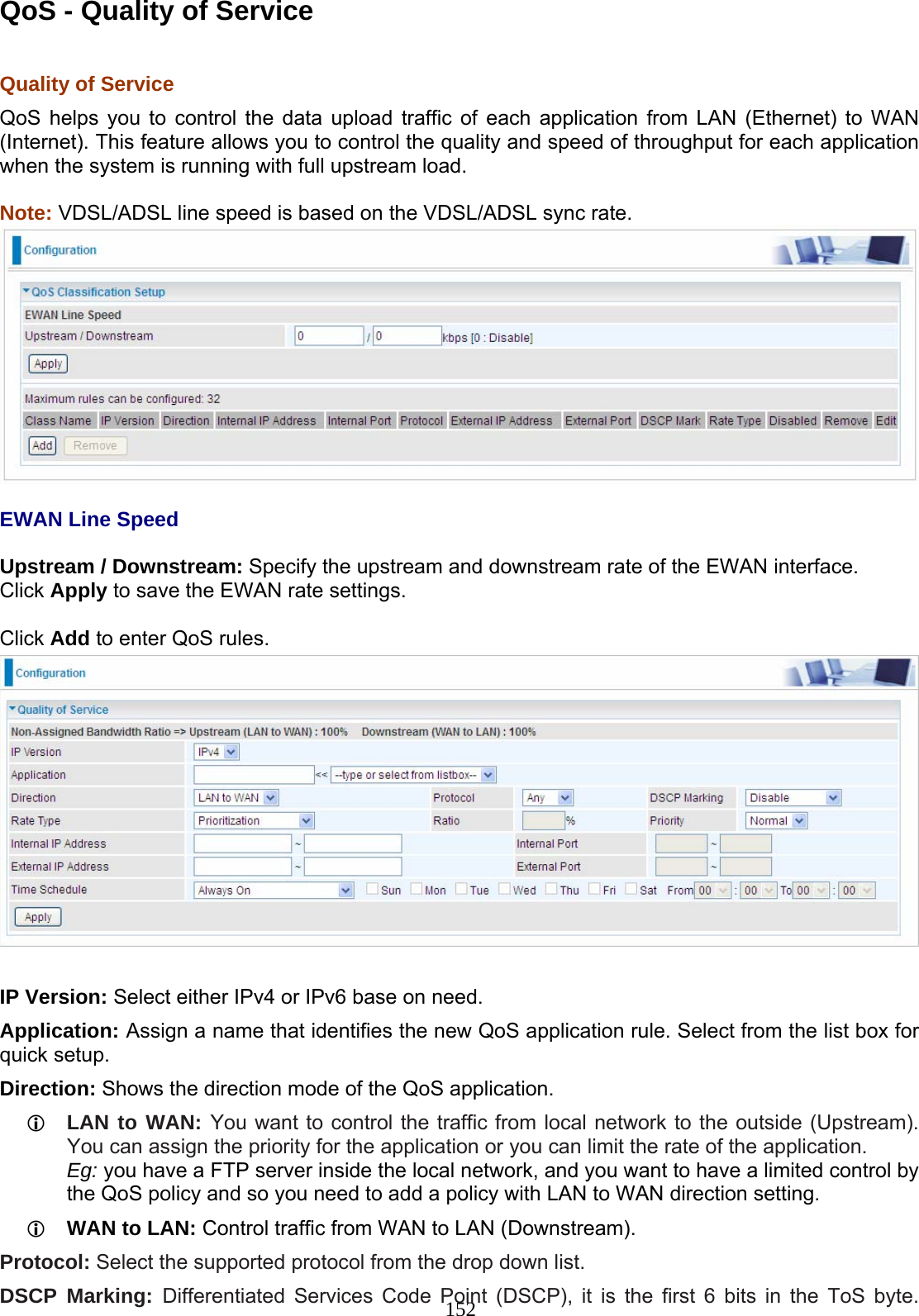
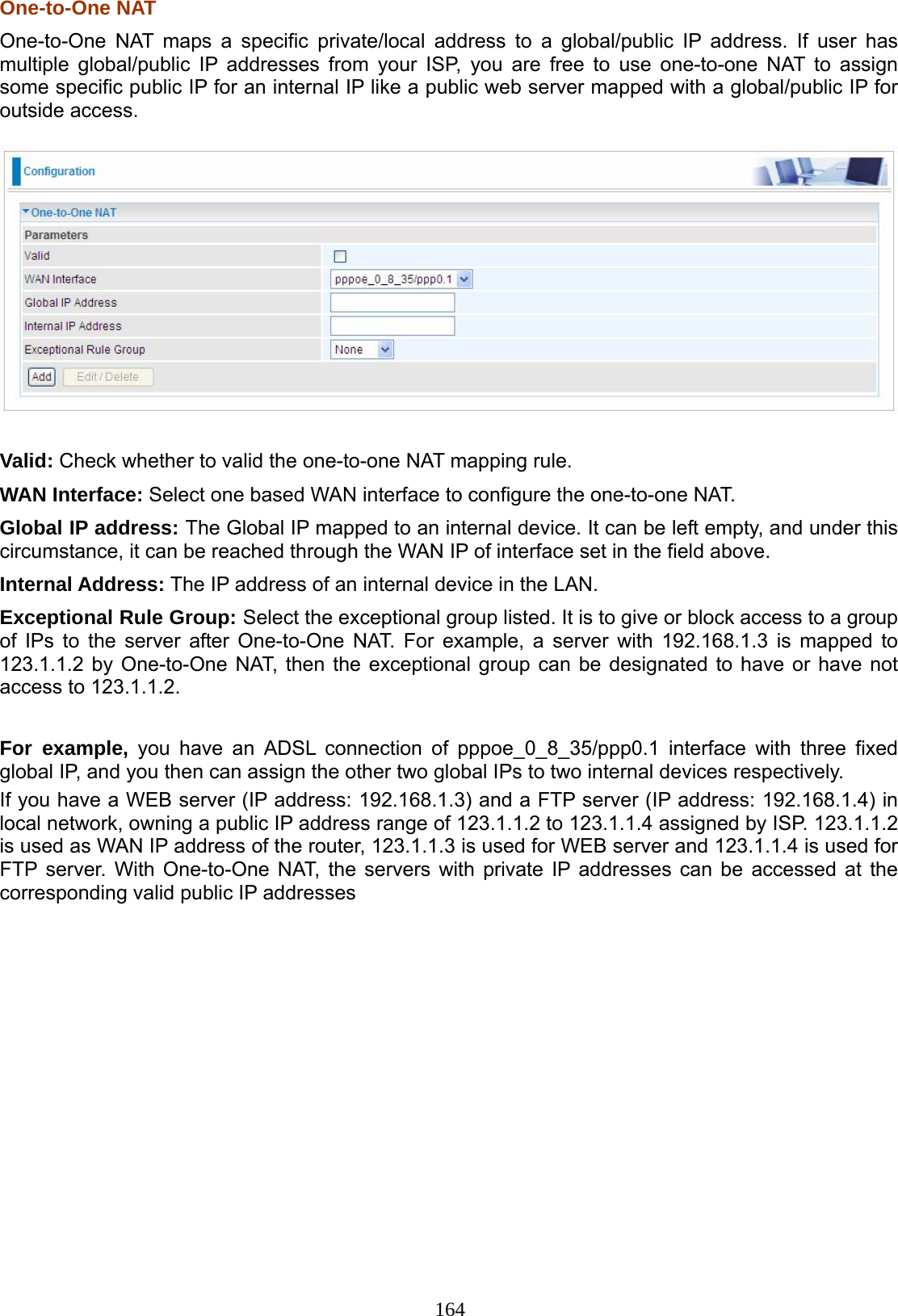
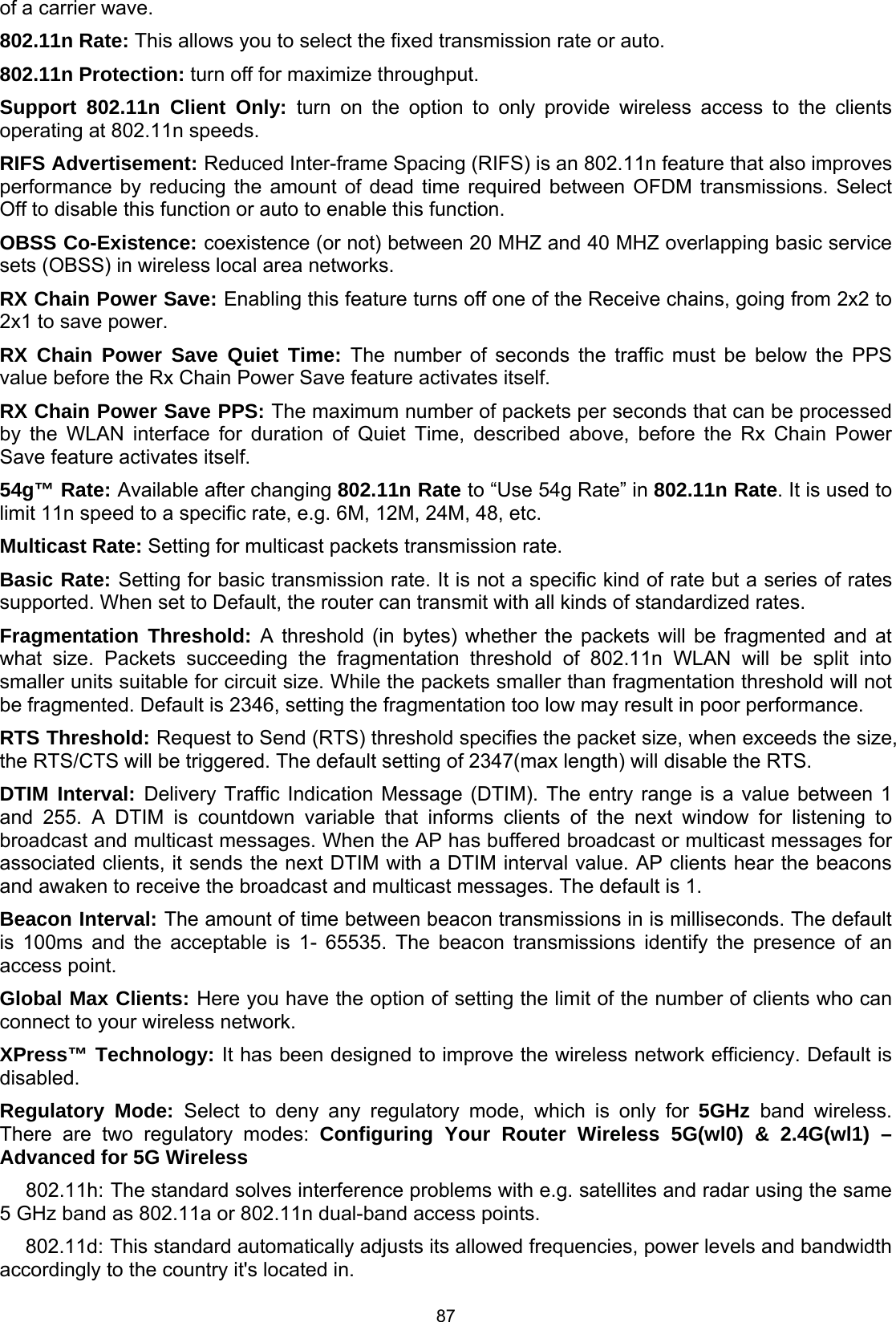
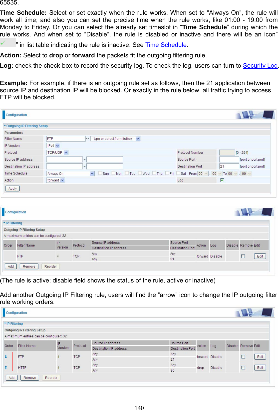
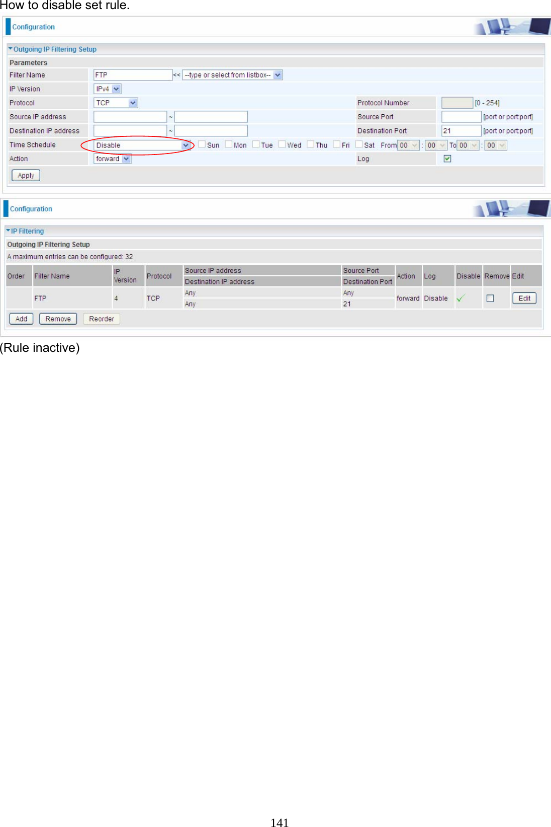
![139 Security IP Filtering Outgoing IP filtering enables you to configure your router to block specified internal/external users (IP address) from Internet access, or you can disable specific service requests (Port number) to /from Internet. The relationship among all filters is “or” operation, which means that the router checks these different filter rules one by one, starting from the first rule. As long as one of the rules is satisfied, the specified action will be taken. Note: The maximum number of entries: 32. Click Add button to enter the exact rule setting page. Filter Name: A user-defined rule name. User can select simply from the list box for the application for quick setup. IP Version: Select the IP Version, IPv4 or IPv6. Protocol: Set the traffic type (TCP/UDP, TCP, UDP, ICMP, RAW, Any) rule applies to. Source IP address: This is the Address-Filter used to allow or block traffic to/from particular IP address(es) featured in the IP range. If you leave empty, it means any IP address. Source Port [port or port:port]: The port or port range defines traffic from the port (specific application) or port in the set port range blocked to go through the router. Default is set port from range 1 – 65535. Destination IP address: Traffic from LAN with the particular traffic destination address specified in the IP range is to be blocked from going through the router, similarly set as the Source IP address above. Destination Port [port or port: port]: Traffic with the particular set destination port or port in the set port range is to be blocked from going through the router. Default is set port from port range: 1 –](https://usermanual.wiki/Billion-Electric/BIL-8920AX.Users-Manual-2/User-Guide-2734658-Page-56.png)
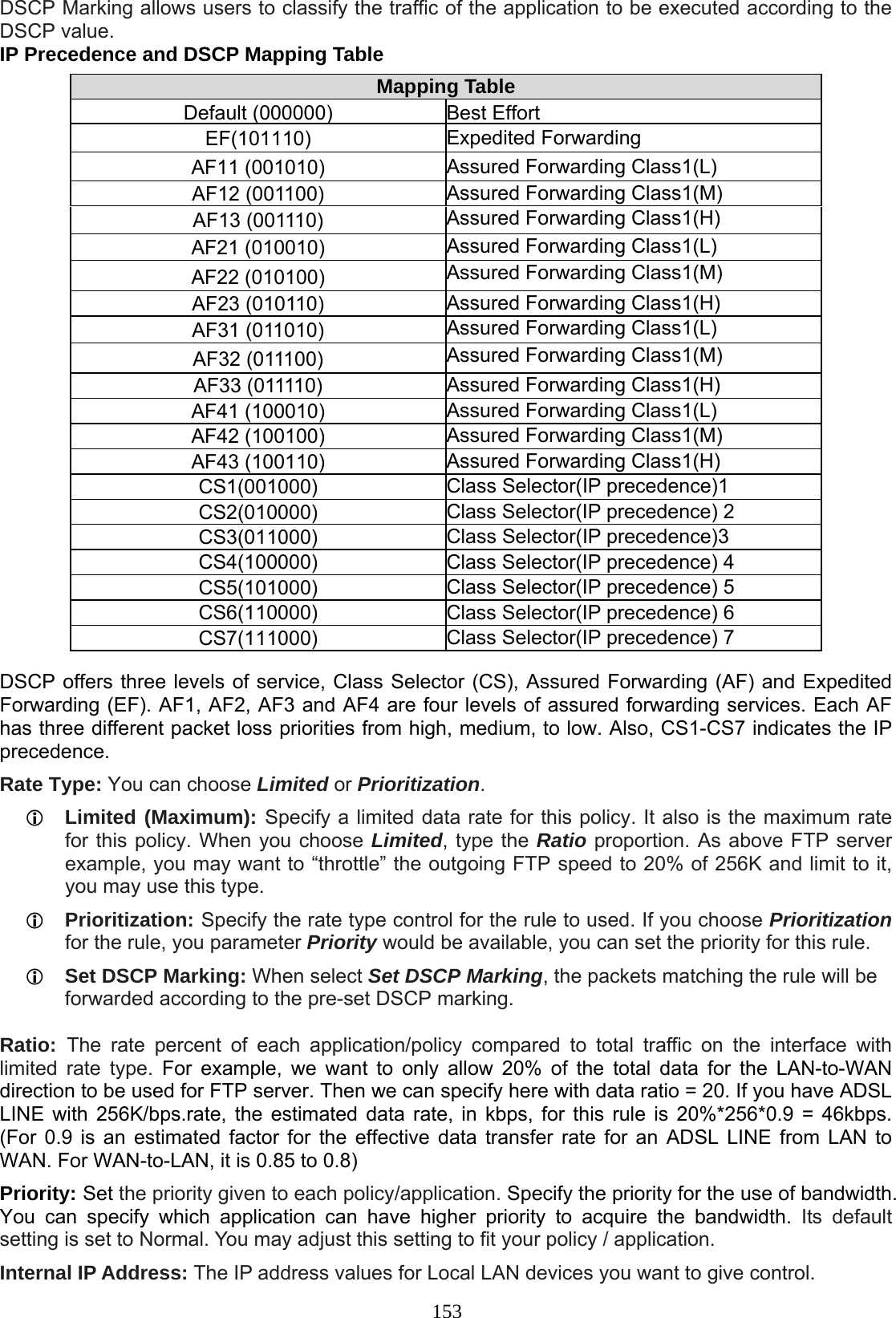
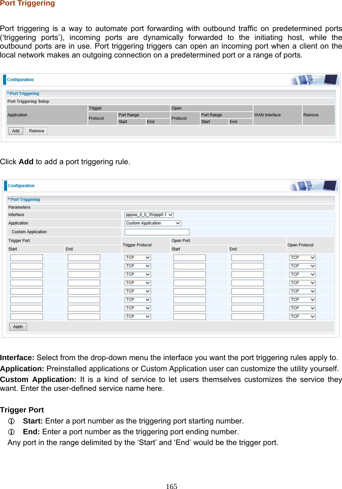
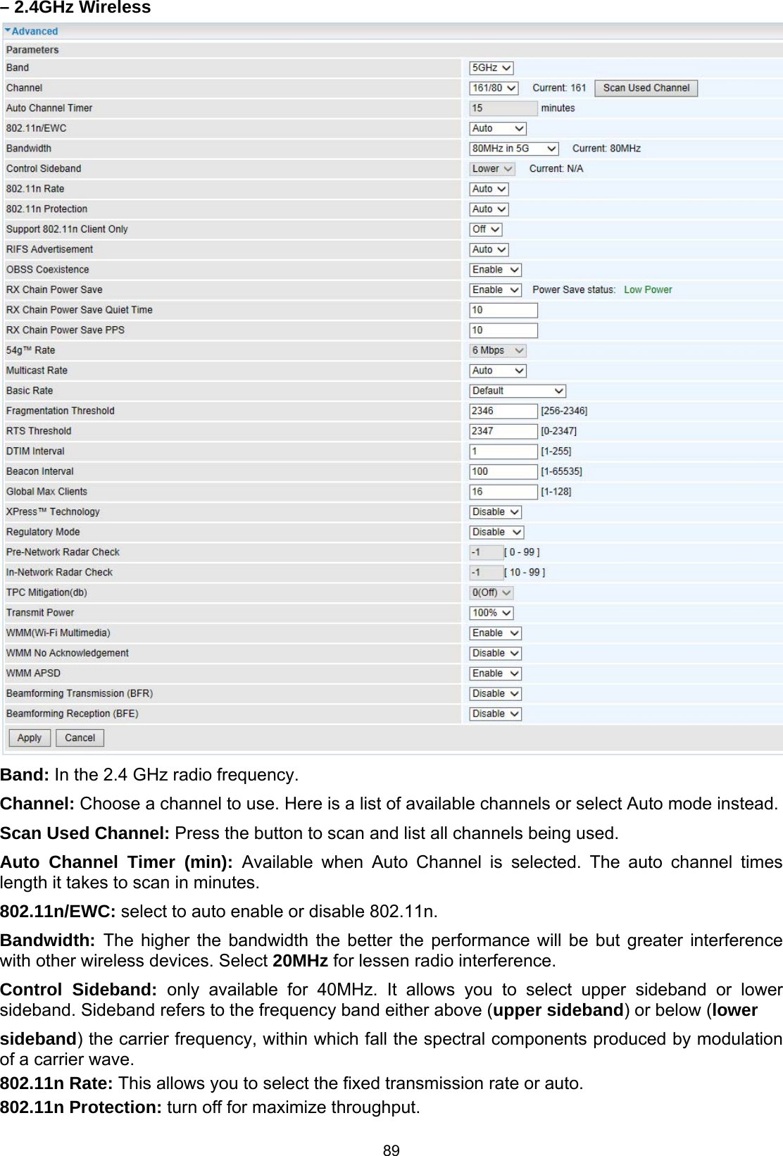
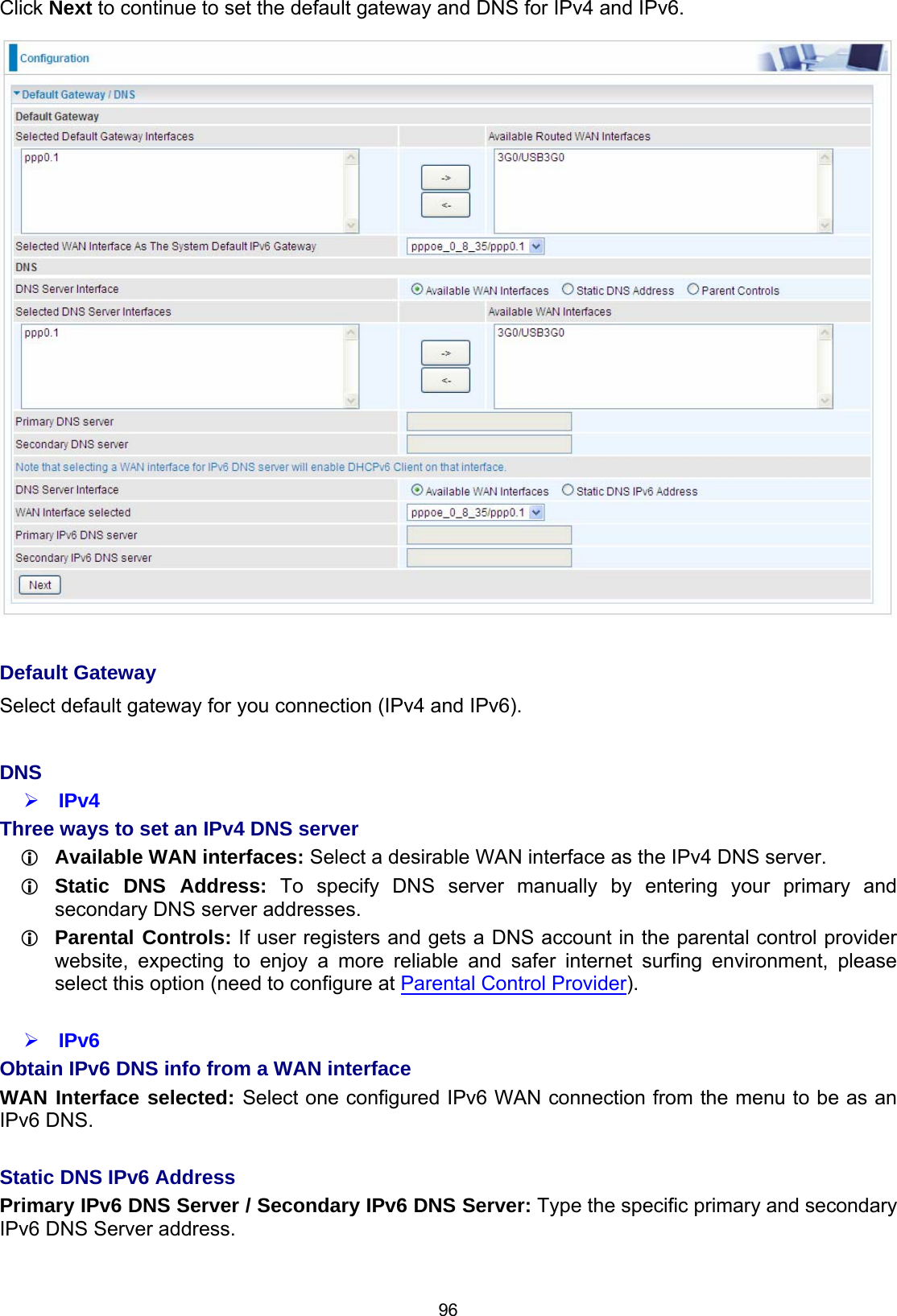
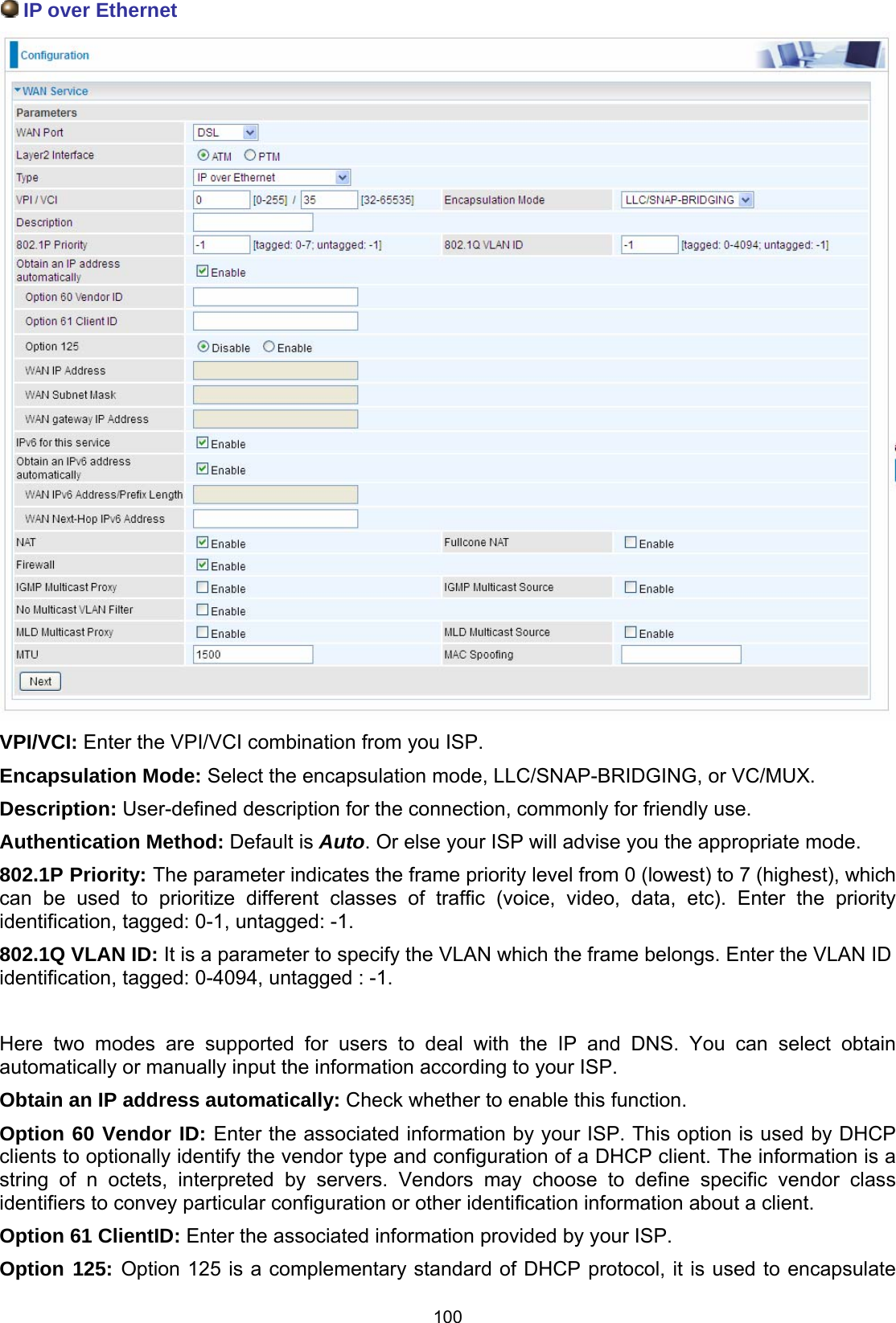
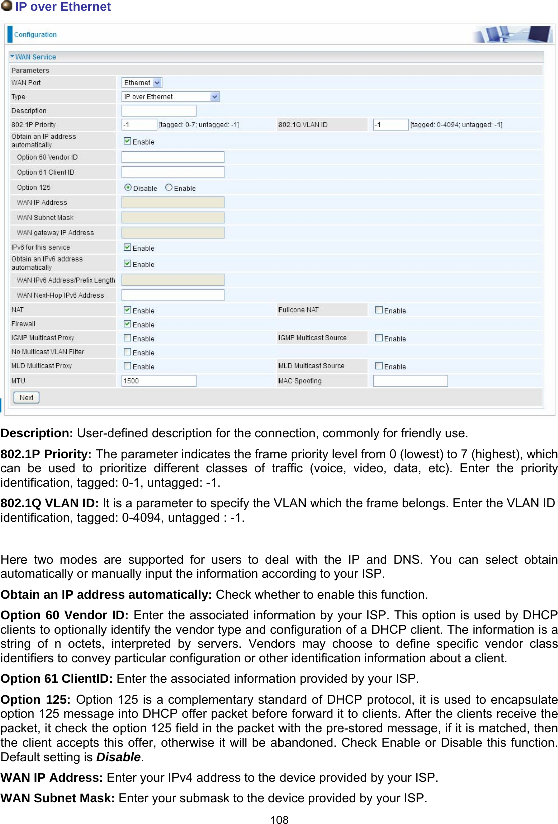
![142 IP Filtering Incoming Incoming IP Filtering is set by default to block all incoming traffic, but user can set rules to forward the specific incoming traffic. Note: 1. The maximum number of entries: 32. 2. When LAN side firewall or firewall in WAN interface(s) is enabled, user can move here to add allowing rules to pass through the firewall. Click Add button to enter the exact rule setting page. Filter Name: A user-defined rule name. User can select simply from the list box for the application for quick setup. IP Version: Select the IP Version, IPv4 or IPv6. Protocol: Set the traffic type (TCP/UDP, TCP, UDP, ICMP, RAW, Any ) that the rule applies to. Source IP address: This is the Address-Filter used to allow or block traffic to/from particular IP address(es) featured in the IP range.. If you leave empty, it means any IP address. Source Port [port or port:port]: The port or port range defines traffic from the port (specific application) or port in the set port range blocked to go through the router. Default is set port from range 1 – 65535. Destination IP address: Traffic from LAN with the particular traffic destination address specified in the IP range is to be blocked from going through the router, similarly set as the Source IP address above. Destination Port [port or port : port]: Traffic with the particular set destination port or port in the set port range is to be blocked from going through the router. Default is set port from port range: 1 – 65535 Interfaces: Check if the filter rule applies to all interfaces. User can base on need select interfaces to make the rule take effect with those interfaces.](https://usermanual.wiki/Billion-Electric/BIL-8920AX.Users-Manual-2/User-Guide-2734658-Page-59.png)