Billion Electric BIL-8920NE The Ultimate Residential Gateway User Manual
Billion Electric Co., Ltd. The Ultimate Residential Gateway Users Manual
UserManual.wiki
>
Billion Electric
>
BIL 8920NE User Manual
Users Manual
Navigation menu
Upload a User Manual
Namespaces
Wiki Guide
HTML
PDF
Info
Views
User Manual
Discussion / Help
Navigation
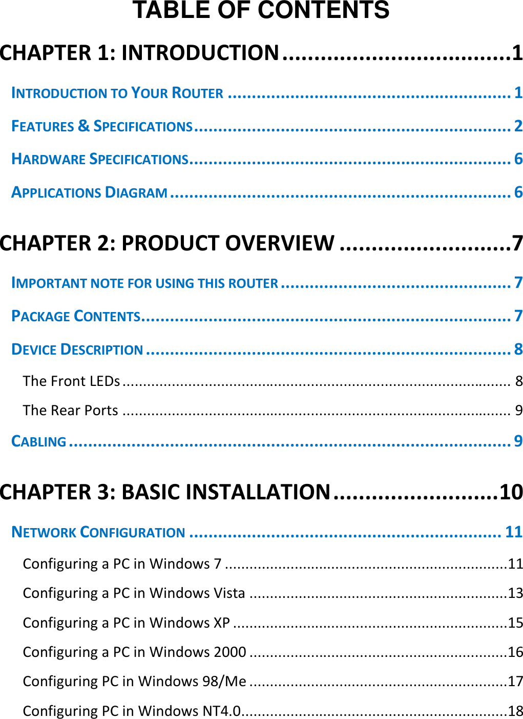
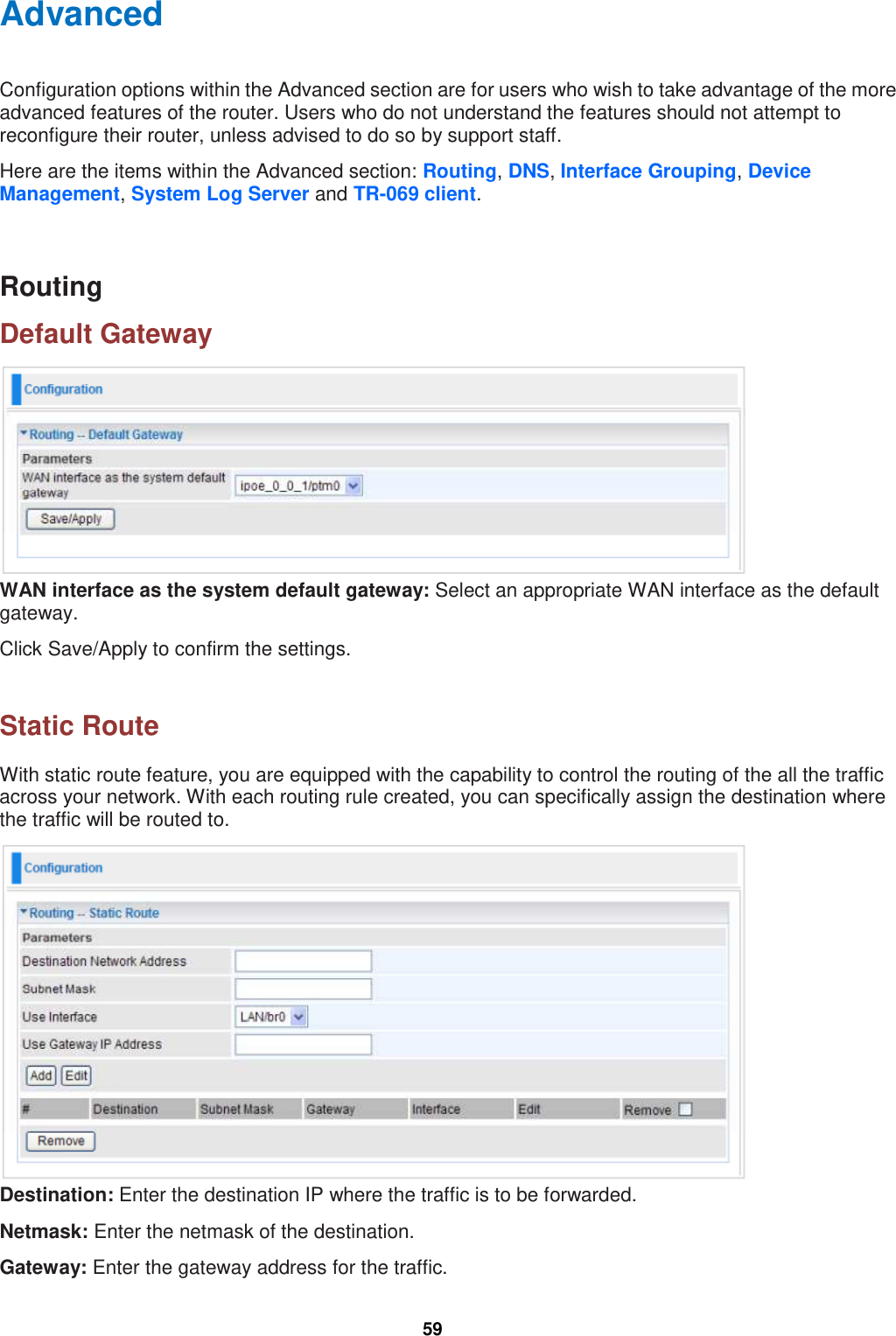
![36 PPP Username: Enter the username provided by your ISP. You can input up to 256 alphanumeric characters (case sensitive). PPP Password: Enter the password provided by your ISP. You can input up to 32 alphanumeric characters (case sensitive). PPPoE Service Name: This item is for identification purposes. If it is required, your ISP will provide you the necessary information. Maximum input is 32 alphanumeric characters. Authentication Method: Default is AUTO. Please consult your ISP on whether to use PAP, CHAP or MSCHAP. Fullcone NAT: Check/uncheck this item to activate/inactivate this function. Dial on demand (with idle timeout timer) / Inactivity Timeout (minutes) [1-4320]: Check Enable to activate this function and the following field will be available, so that you can enter the time value to auto-disconnect the broadband firewall gateway when there is no activity on the line for a predetermined period of time. PPP IP extension: Check/uncheck this item to enable/disable this function. Static IPv4 Address / IPv4 Address: Check Enable to activate this function and the following field will be available, so that you can enter the IPv4 address (default is 0.0.0.0) to the device. PPP Debug Mode: Check/uncheck this item to enable/disable this function. Bridge PPPoE Frames Between WAN and Local Ports: Check/uncheck this item to enable/disable this function. IGMP Multicast Proxy: Check/uncheck this item to enable/disable this function. Click Next to go to next step.](https://usermanual.wiki/Billion-Electric/BIL-8920NE/User-Guide-2002845-Page-39.png)
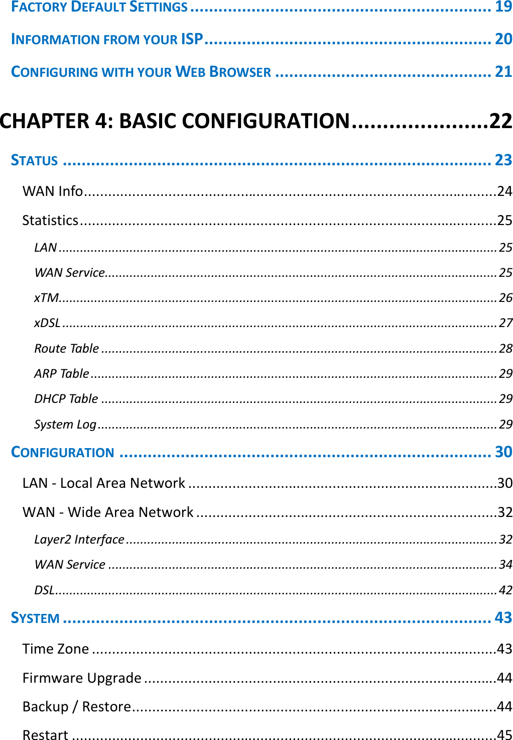
![74 Appendix: Product Support & Contact If you come across any problems please contact the dealer from where you purchased your product. Contact BEC http://www.bectechnologies.net FCC Caution:Any Changes or modifications not expressly approved by the party responsible for compliance could void the user's authority to operate the equipment. This device complies with part 15 of the FCC Rules. Operation is subject to the following two conditions:(1) This device may not cause harmful interference, and (2) this device must accept any interference received, including interference that may cause undesired operation. IMPORTANT NOTE: FCC Radiation Exposure Statement: This equipment complies with FCC radiation exposure limits set forth for an uncontrolled environment .This equipment should be installed and operated with minimum distance 20cm between the radiator& your body. This transmitter must not be co-located or operating in conjunction with any other antenna or transmitter. Note: This equipment has been tested and found to comply with the limits for a class B digital device,pursuant to part 15 of the FCC rules.This limits are designed to provide reasonable protection against harnful interenference in a residential installation . this equipment generates ,uses and can radiate radio frequency energy and ,if not installed and used in accordance with the instructionsmay case harmful interference to radio communication.However, there is no grantee will not occur in a particular installation.If this equipment doses cause harmful interference to radio or television reception ,which can be determined by turning the equipment off and on , the user is encourage to try to correct the interference by one or more of the following mersures: -Reorient or relocate the receiving antenna. -Increase the separation between the equipment and receiver. -Connect the equipment into an outlet on a circuit different from that to which the receiver is connected. -Consult the dealer or an experienced radio/TV technician for help. Customer Information1.This equipment complies with Part 68 of the FCC rules and the requirements adopted by the ACTA. On the bottom of this equipment is a label that contains, among other information, a product identifier in the format US:AAAEQ##TXXXX. If requested, this number must be provided to the telephone company.2.A plug and jack used to connect this equipment to the premises wiring and telephone network must comply with the applicable FCC Part 68 rules and requirements adopted by the ACTA. A compliant telephone cord and modular plug is provided with this product. It is designed to be connected to a compatible modular jack that is also compliant. See installation instructions for details.3.If this equipment [US: B12DL01B8920NE] causes harm to the telephone network, the telephone company will notify you in advance that temporary discontinuance of service may be required. But if advance notice isn't practical, the telephone company will notify the customer as soon as possible. Also, you will be advised of your right to file a complaint with the FCC if you believe it is necessary4.The telephone company may make changes in its facilities, equipment, operations or procedures that could affect the operation of the equipment. If this happens the telephone company will provide advance notice in order for you to make necessary modifications to maintain uninterrupted service.5.If trouble is experienced with this equipment [US: B12DL01B8920NE], for repair or warranty information, Service can be facilitated through our office at:U.S. Agent Company name:BEC Technologies Inc.Address:1500 Precision Drive, Suite 100 Plano TX 75074 USATel:+1-972-422-0877If the equipment is causing harm to the telephone network, the telephone company may request that you disconnect the equipment until the problem is resolved.6.Please follow instructions for repairing if any (e.g. battery replacement section); otherwise do not alternate or repair any partsof device except specified. For repair procedures, follow the instructions outlined under the limited warranty. 7.Connection to party line service is subject to state tariffs. Contact the state public utility commission, public service commission or corporation commission for information. 8.If your home has specially wired alarm equipment connected to the telephone line, ensure the installation of this [8920NE]does not disable your alarm equipment. If you have questions about what will disable alarm equipment, consult your telephone company or a qualified installer.9.If the telephone company requests information on what equipment is connected to their lines, inform them of:a)The ringer equivalence number[ 0.1B]b)The USOC jack required [RJ11C]c)Facility Interface Codes ("FIC") [METALLIC]d)Service Order Codes ("SOC") [9.0Y]e)The FCC Registration Numbe [US:B12DL01B8920NE]10.The REN is used to determine the number of devices that may be connected to a telephone line. Excessive RENs on a telephone line may result in the devices not ringing in response to an incoming call. In most but not all areas, the sum of RENs should not exceed five (5.0). To be certain of the number of devices that may be connected to a line, as determined by the total RENs, contact the local telephone company. The REN for this product is part of the product identifier that has the format US:AAAEQ##TXXXX. The digits represented by ## are the REN without a decimal point. For this product the FCC Registration number is [US: B12DL01B8920NE] indicates the REN would be 0.1. MAC OS is a registered Trademark of Apple Computer, Inc. Windows 7/98, Windows NT, Windows 2000, Windows Me, Windows XP and Windows Vista are registered Trademarks of Microsoft Corporation.](https://usermanual.wiki/Billion-Electric/BIL-8920NE/User-Guide-2002845-Page-77.png)