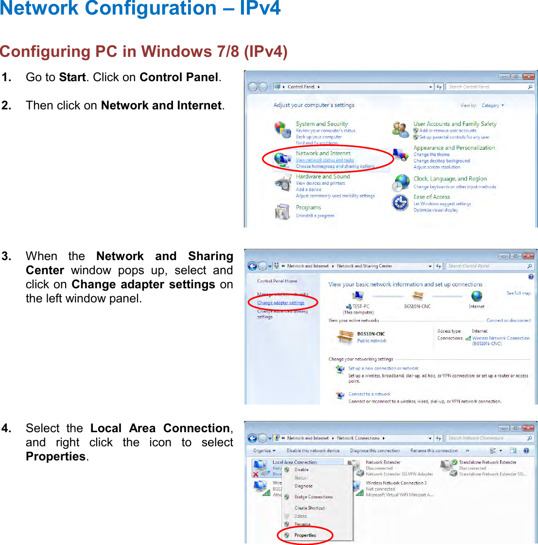
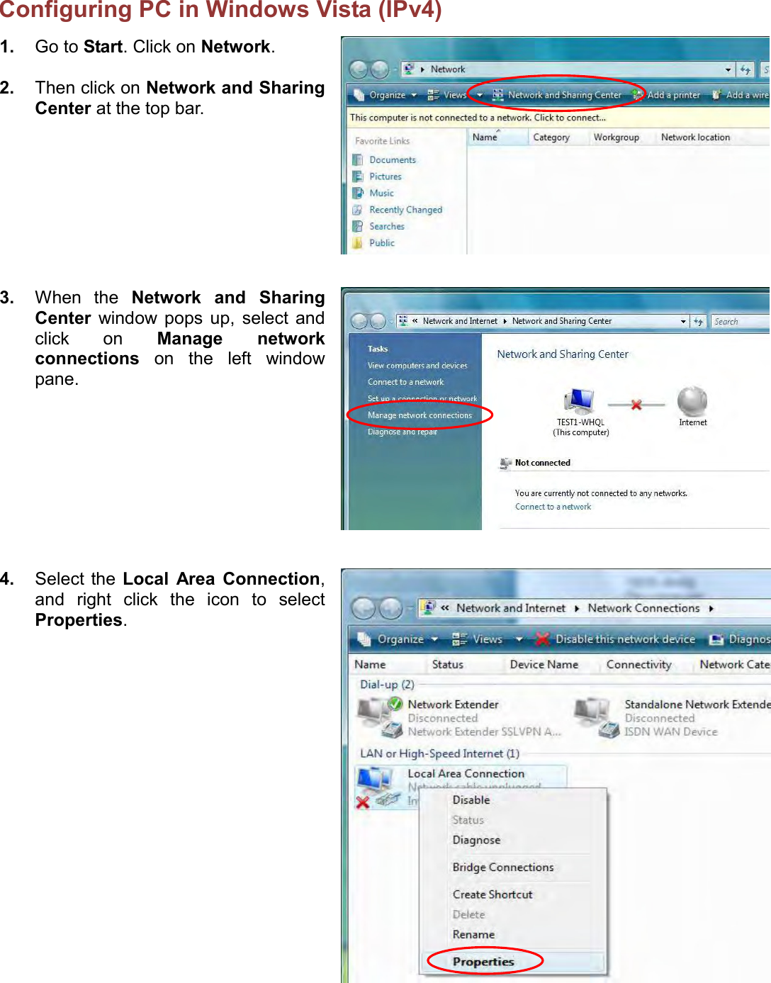
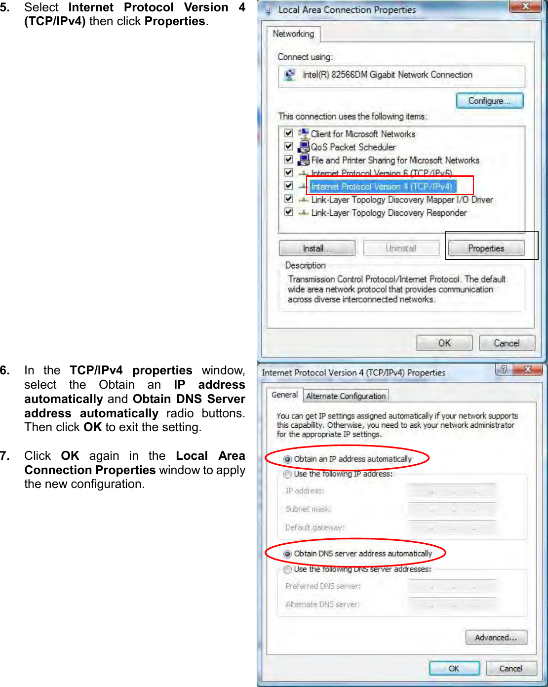
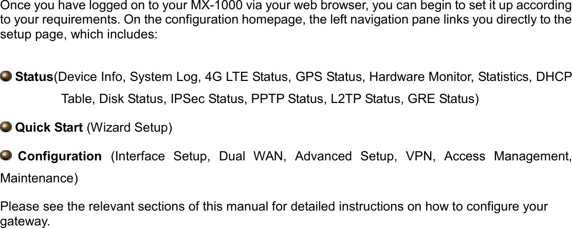
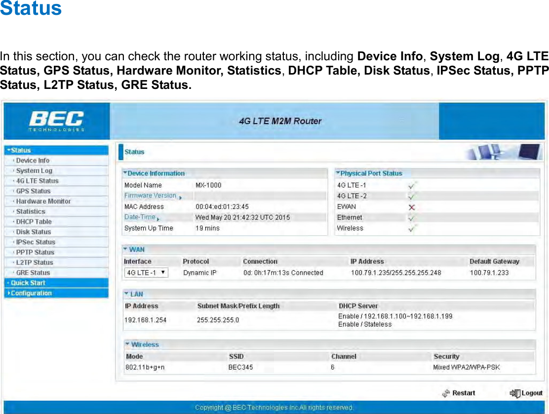
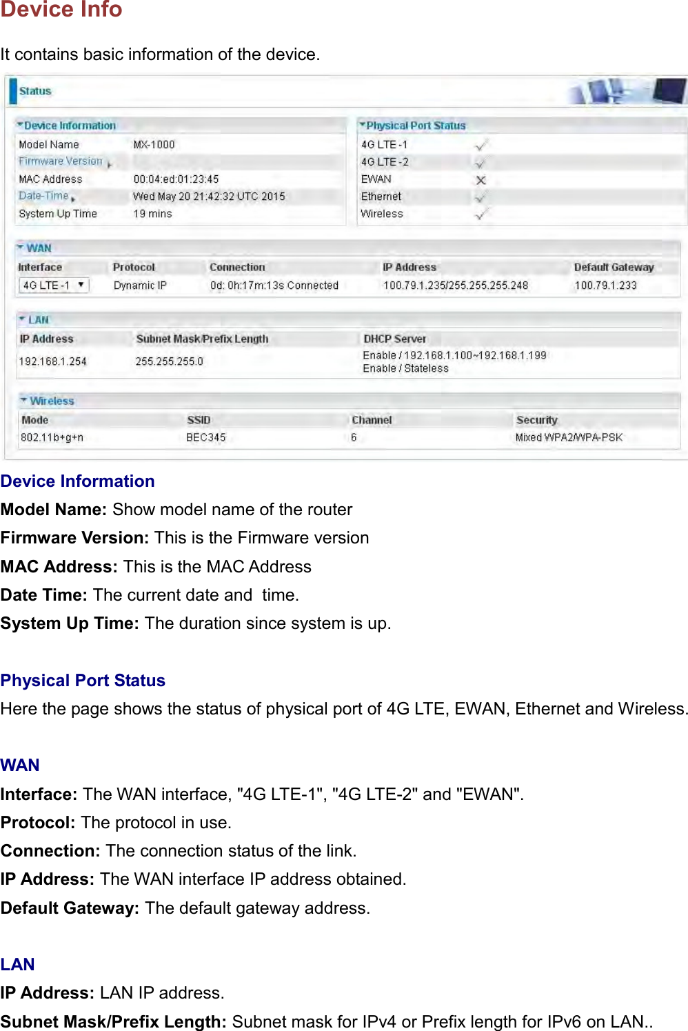
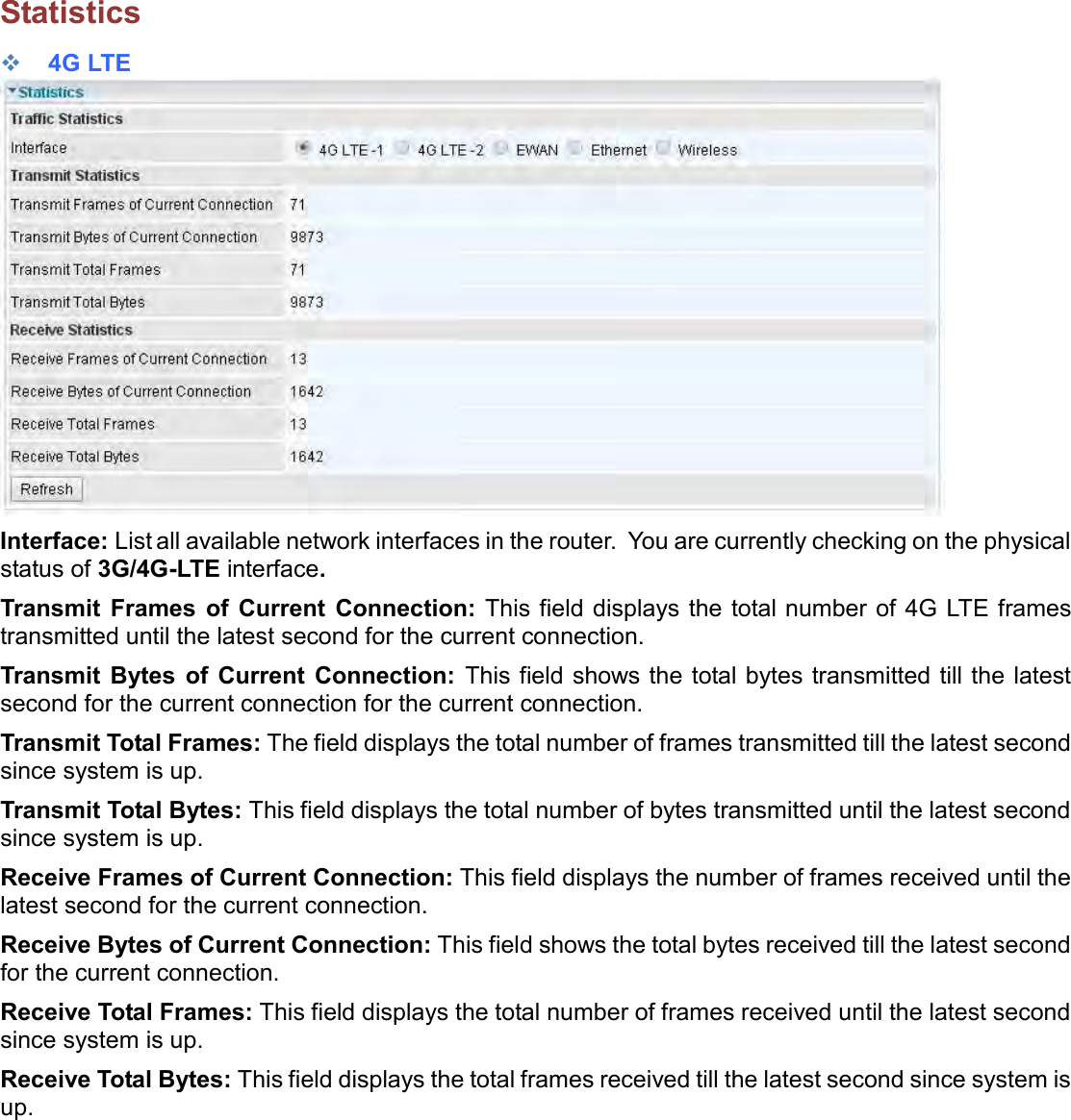
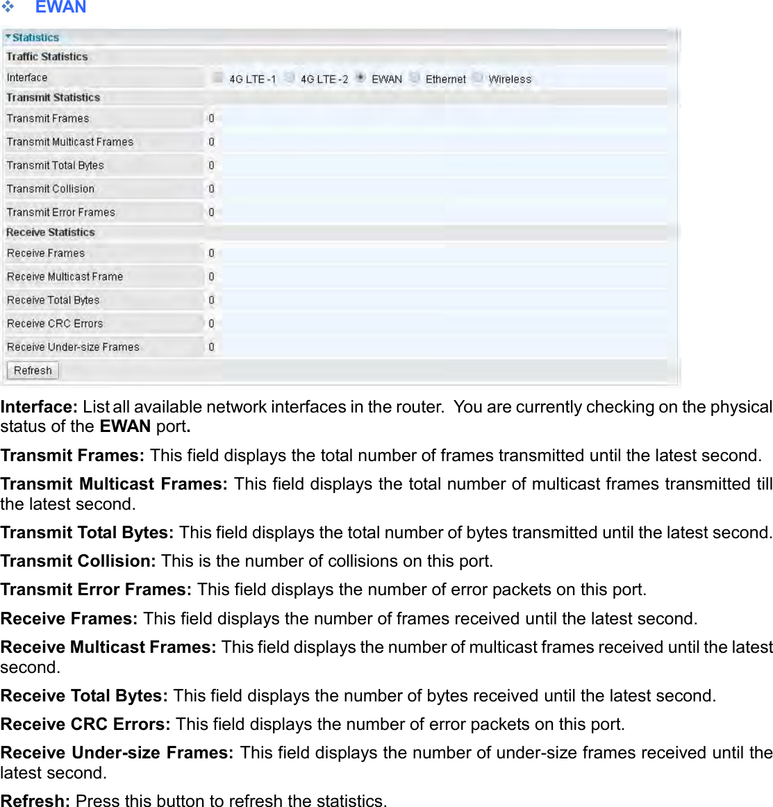
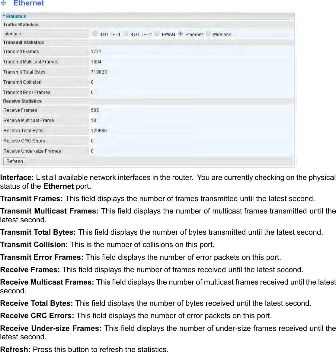
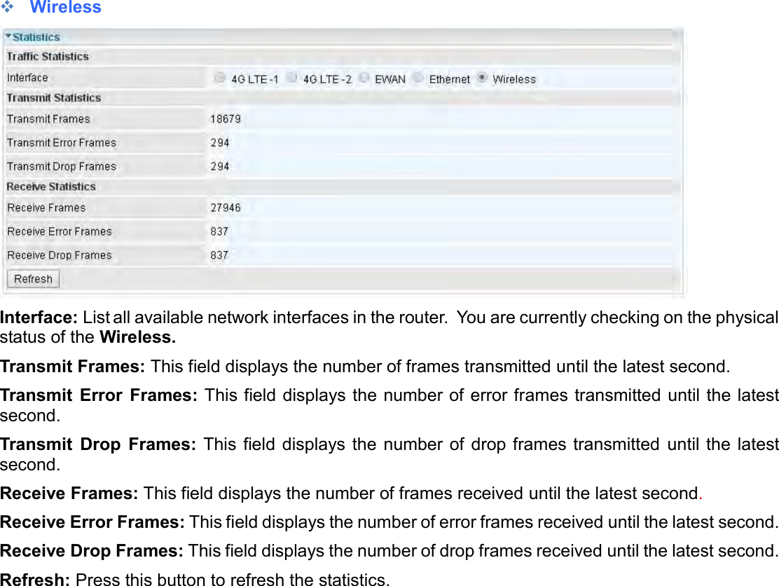
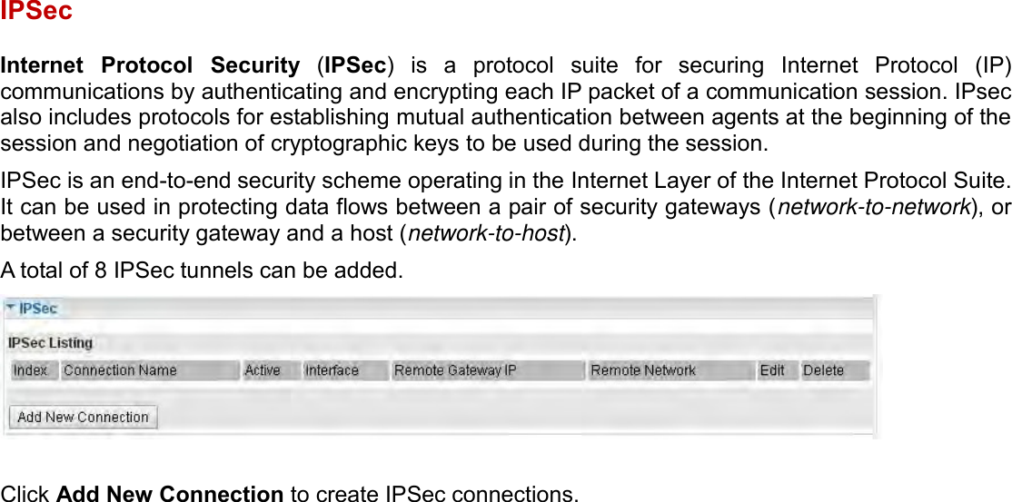
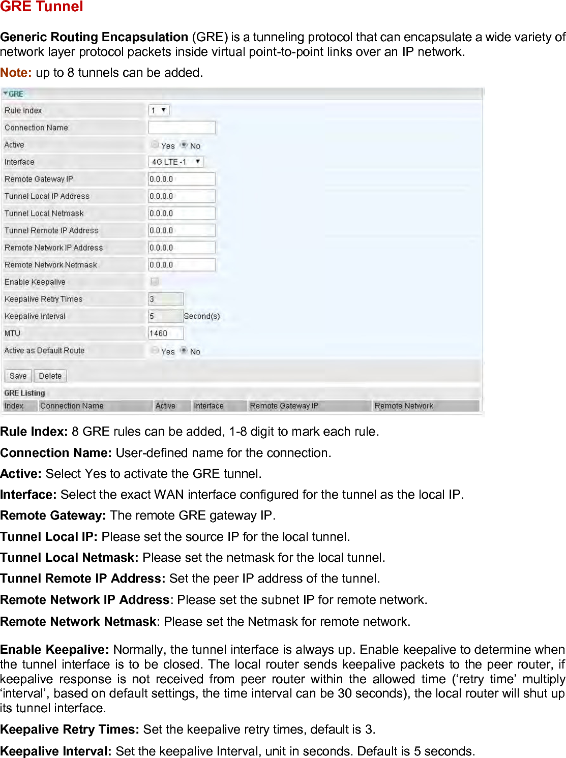
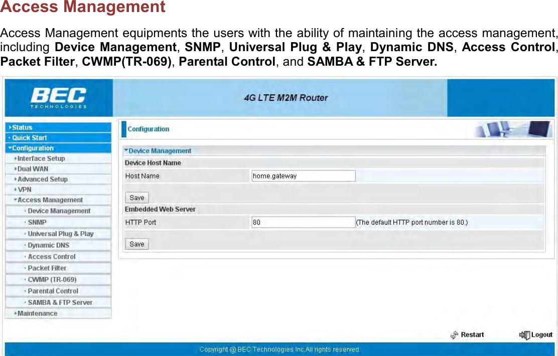
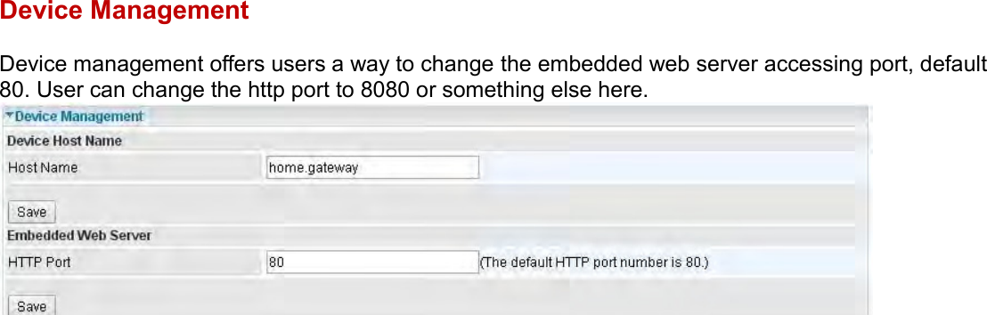
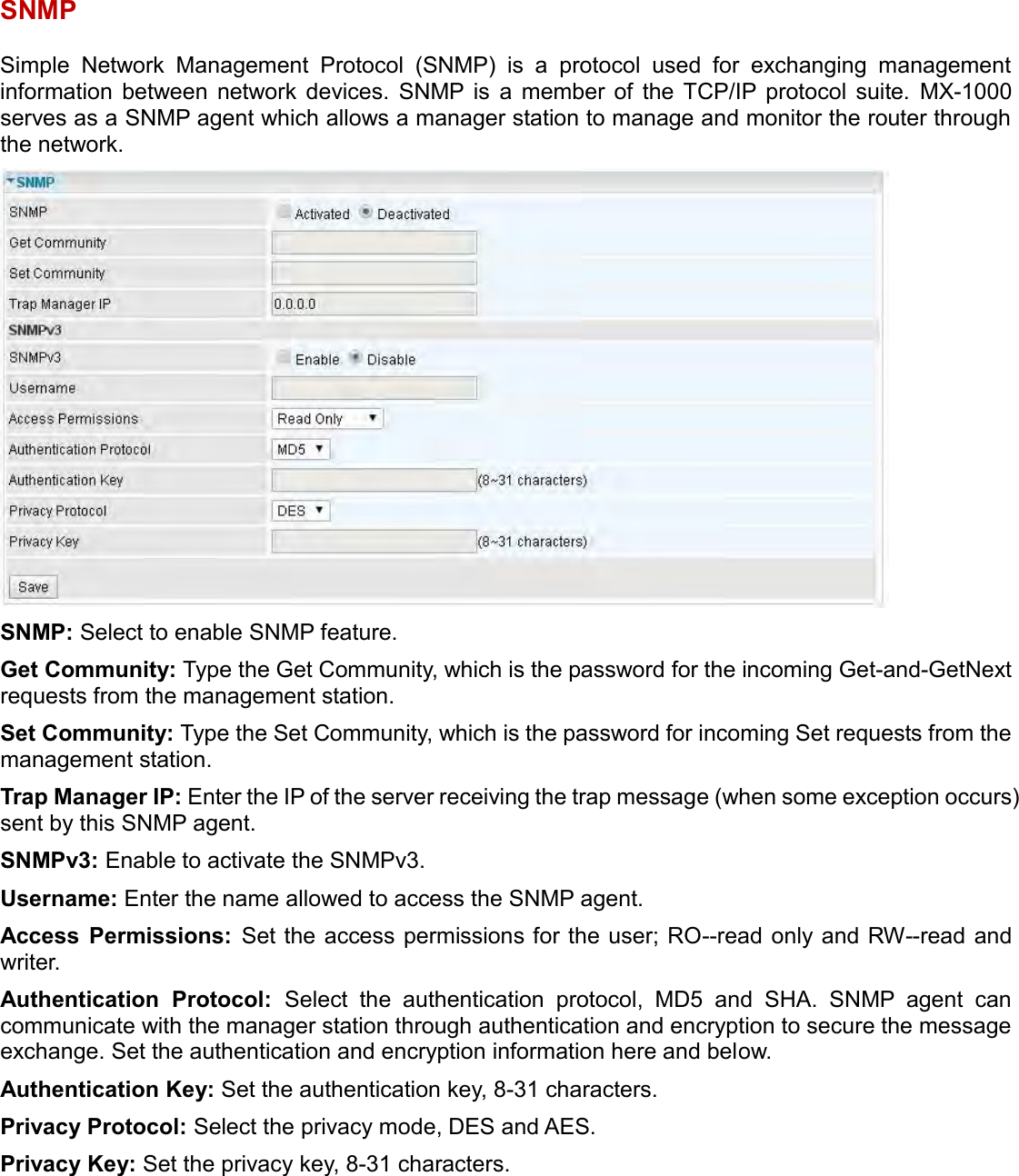
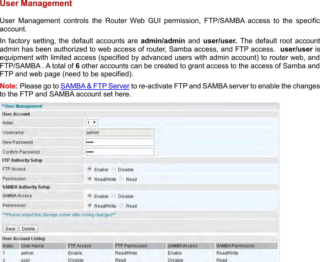
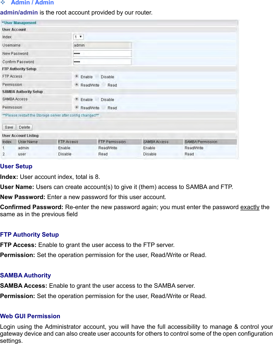
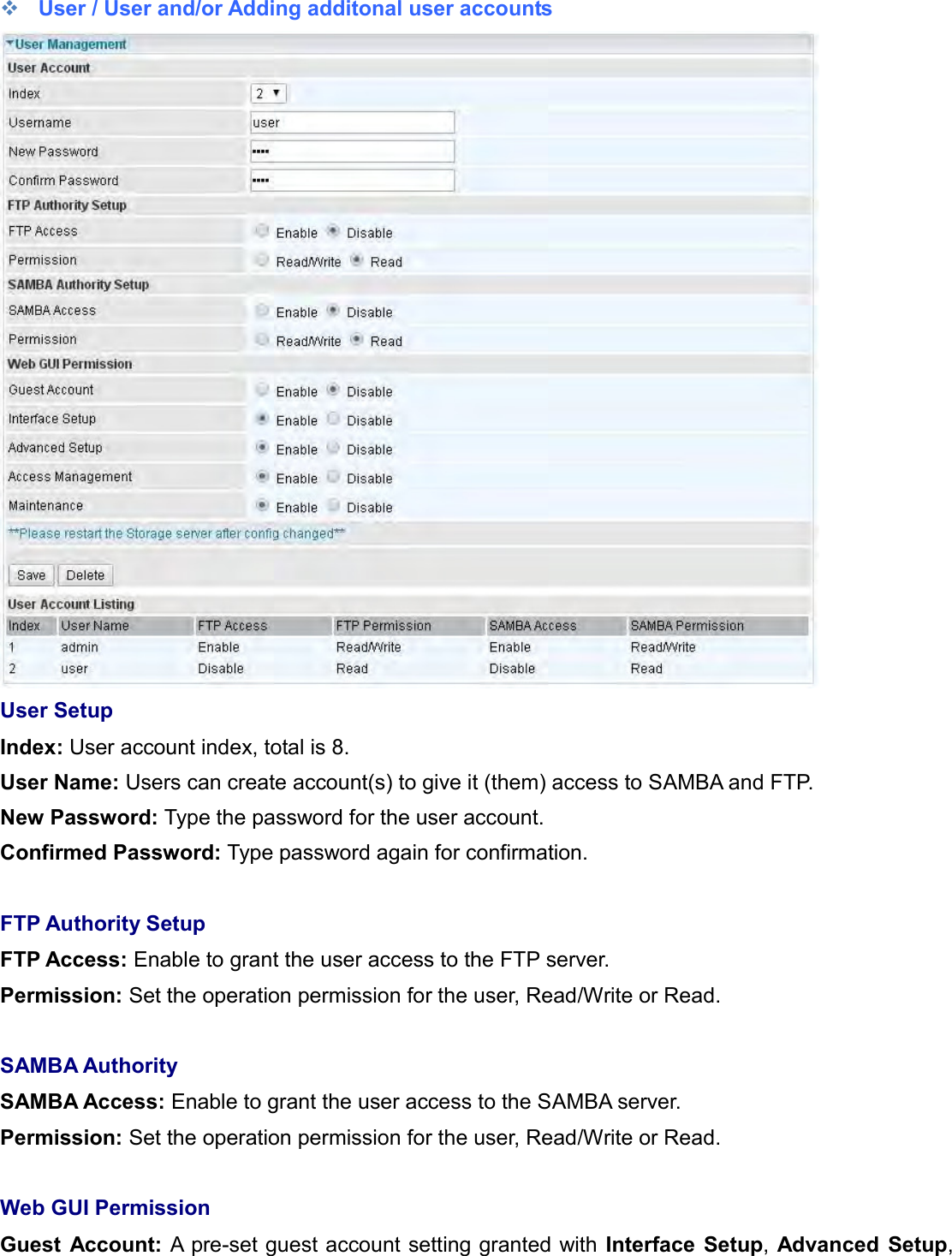
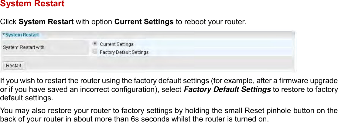
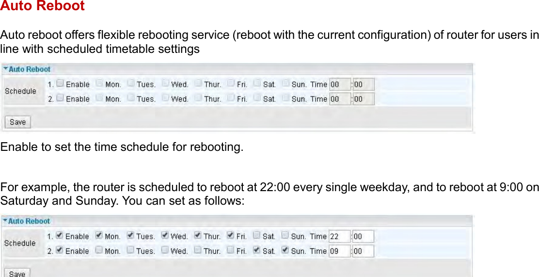
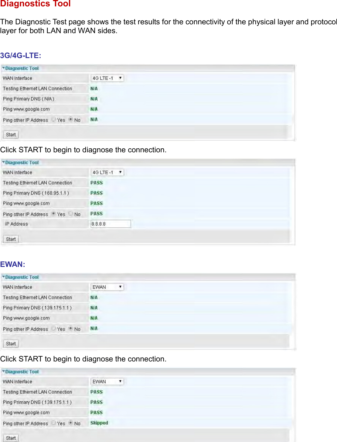
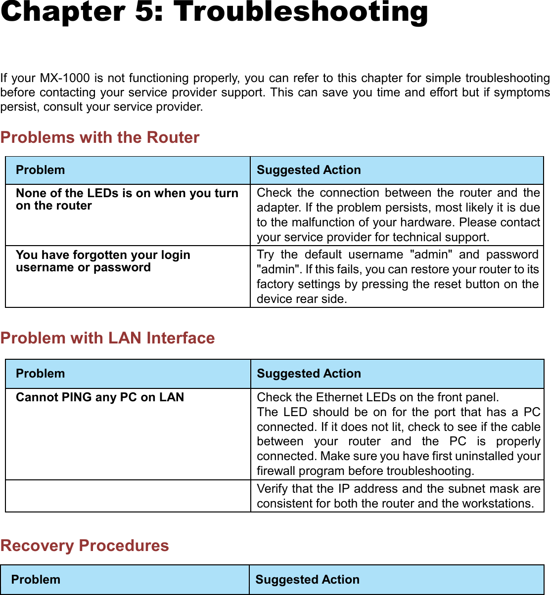
Billion Electric BIL-MX1000 MXConnect M2M Advanced In-Vehicle 4G/LTE Wireless Router, MXConnect M2M Wireless Router User Manual Basic Installation

Billion Electric Co., Ltd. MXConnect M2M Advanced In-Vehicle 4G/LTE Wireless Router, MXConnect M2M Wireless Router Basic Installation

Contents

User manual

Last revised date: June 18, 2015                       BEC MX-1000    MXConnect M2M Advanced In-Vehicle 4G LTE Wireless Router       User Manual           Version release: 1.01.1.8_v1
  Table of Contents  Chapter 1: Introduction .............................................................................................................................. 4 Introduction to your Router .................................................................................................................... 4 Features & Specifications ........................................................................................................................ 6 Hardware Specifications ......................................................................................................................... 9 Application Diagram ............................................................................................................................. 10 Chapter 2: Product Overview .................................................................................................................... 11 Important Note for Using This Router.................................................................................................... 11 Device Description ................................................................................................................................ 12 The detail instruction in Reset Button ................................................................................................... 15 Cabling ................................................................................................................................................. 16 Chapter 3: Basic Installation ..................................................................................................................... 17 Network Configuration – IPv4 ............................................................................................................... 18 Configuring PC in Windows 7/8 (IPv4) .......................................................................................................... 18 Configuring PC in Windows Vista (IPv4) ...................................................................................................... 20 Configuring PC in Windows XP (IPv4) .......................................................................................................... 22 Network Configuration – IPv6 ............................................................................................................... 23 Configuring PC in Windows 7/8 (IPv6) .......................................................................................................... 23 Configuring PC in Windows Vista (IPv6) ...................................................................................................... 25 Configuring PC in Windows XP (IPv6) .......................................................................................................... 27 Default Settings .................................................................................................................................... 28 Information from Your ISP .................................................................................................................... 29 Chapter 4: Device Configuration ............................................................................................................... 30 Login to your Device ............................................................................................................................. 30 Status ................................................................................................................................................... 32 Device Info ................................................................................................................................................... 33 System Log ................................................................................................................................................... 35 3G/4G-LTE Status .......................................................................................................................................... 36 GPS Status .................................................................................................................................................... 37 Hardware Monitor ....................................................................................................................................... 38 Statistics ....................................................................................................................................................... 39 DHCP Table ................................................................................................................................................... 43 Disk Status .................................................................................................................................................... 44 IPSec Status .................................................................................................................................................. 45 PPTP Status .................................................................................................................................................. 46 L2TP Status ................................................................................................................................................... 47 GRE Status .................................................................................................................................................... 48 Quick Start ........................................................................................................................................... 49 Configuration ....................................................................................................................................... 52
  Interface Setup ............................................................................................................................................ 53 Internet .................................................................................................................................................... 54 LAN........................................................................................................................................................... 60 Wireless ................................................................................................................................................... 64 Wireless MAC Filter ................................................................................................................................. 74 Dual WAN ..................................................................................................................................................... 75 General Setting ........................................................................................................................................ 75 Outbound Load Balance .......................................................................................................................... 79 Protocol Binding ....................................................................................................................................... 80 Advanced Setup ........................................................................................................................................... 81 Firewall .................................................................................................................................................... 82 Routing ..................................................................................................................................................... 83 NAT ........................................................................................................................................................... 84 Static DNS ................................................................................................................................................ 89 Time Schedule ......................................................................................................................................... 90 Mail Alert ................................................................................................................................................. 92 Remote System Log.................................................................................................................................. 93 VPN .............................................................................................................................................................. 94 IPSec ......................................................................................................................................................... 95 PPTP Server ............................................................................................................................................ 105 PPTP Client ............................................................................................................................................. 107 L2TP........................................................................................................................................................ 113 GRE Tunnel ............................................................................................................................................. 123 Access Management .................................................................................................................................. 125 Device Management .............................................................................................................................. 126 SNMP ..................................................................................................................................................... 127 Universal Plug & Play ............................................................................................................................. 128 Dynamic DNS ......................................................................................................................................... 129 Access Control ........................................................................................................................................ 131 Packet Filter ........................................................................................................................................... 133 CWMP (TR-069) ..................................................................................................................................... 137 Parental Control ..................................................................................................................................... 139 SAMBA & FTP Server.............................................................................................................................. 140 Maintenance .............................................................................................................................................. 143 User Management ................................................................................................................................. 144 Time Zone .............................................................................................................................................. 150 Firmware & Configuration ..................................................................................................................... 151 System Restart ....................................................................................................................................... 152 Auto Reboot ........................................................................................................................................... 153 Diagnostics Tool ..................................................................................................................................... 154 Chapter 5: Troubleshooting .................................................................................................................... 155 Problems with the Router ......................................................................................................................... 155 Problem with LAN Interface ...................................................................................................................... 155 Recovery Procedures ................................................................................................................................. 155 Appendix: Product Support & Contact ..................................................................................................... 157
   Chapter 1: Introduction Introduction to your Router Embedded Dual 4G LTE Industrial Router MX-1000, Embedded Dual 4G LTE Industrial Router, is integrated with the 802.11n Wireless Access Point  and  Dual  WAN  interfaces  featuring  reliable  connectivity  and  network  expandability.  This cutting-edge networking device provides multi-GNSS engine for GPS, GLONASS, Galileo and QZSS system  for  remotely  tracking  and  monitoring  vehicles.  M1000  is  uniquely  installed  dual  4G  LTE modules enabling an extensive range of mission-critical markets to enjoy a robust, always-on Internet experience by plugging dual SIMs. Fallback and Failover between dual 4G LTE connections supports a seamless wireless connection and is perfectly suitable for industrial M2M applications, ranging from fleet  management,  public  safety,  smart  bus  &  transportation, automotive,  agriculture,  construction, and retail services.  Extraordinary Connectivity with Solid Data Protection The  MX-1000  features  a  rugged,  compact  design  with  integrated  dual  4G  LTE  WAN  ports,  4-port Gigabit  Ethernet  switch,  802.11n  Wi-Fi  access  point  with  multiple  SSID  supports,  and  two multi-function USB 2.0 host interfaces for Storage/NAS. SPI firewall, and advanced VPN integration provide  security  needed  to  enhance  the  operations  of  Public  Safety,  Energy  Wellhead  and  Gas Industry,  Industrial  M2M  Segment,  PoS/Kiosks/ATM,  Fleet  Management,  and  Smart Transportation/Bus.  Vehicle Tracking System MX-1000  is  embedded  with  a  GNSS  receiver  for  GPS  or  GLONASS.  To  co-work  with  On-Board Diagnostics(OBD) system, it eases the central control of geographically-dispersed fleets by presenting individual  vehicles'  detailed  information,  including  remaining  fuel  levels,  rapid  accelerations,  and locations.  Robust Design to Withstand in the Harshest Environments The  industrial-grade  enclosure  is  designed  to  resist  heat,  dust,  moisture  and  provides  long-term operation in the toughest of environments. M1000 supports an extended temperatures range from -40 to 140º F ( -40 to 60º C) for extremely challenging conditions such as industrial automation, mining plants, wellhead & gas drilling, manufacturing factories, and virtually anywhere that requires a robust wireless connection.  The Future of Internet Connectivity - 4G LTE To offer an advanced network solution that meets the growing demands of M2M services, MX-1000 exclusively  features  dual  WAN  -  load  balance  or  auto-failover/failback  to  provide  extraordinary, always-on internet connectivity. In addition to the deployment of dual 4G LTE modules and dual SIMs, MX-1000  broadens  wireless  coverage  to  rough  terrains  and  rural  areas  and  persists  seamless connectivity without interruptions.
   Secure VPN Connections The MX-1000 supports comprehensive and robust IPSec VPN (Virtual Private Network) protocols for business  users  to  establish  private  encrypted  tunnels  over  the  public  Internet  to  secure  data transmission  between  headquarters  and  branch  offices.  It  also  supports  VPN  dial  in  from  smart phones for secure remote Internet connection via your home broadband. With a built-in DES/3DES VPN accelerator, the router enhances IPSec VPN performance significantly.  IPv6 Supported Internet Protocol version 6 (IPv6) is a version of the Internet Protocol that is designed to succeed IPv4. IPv6 has a vastly larger address space than IPv4. The router is already supporting IPv6, you can use it  in  IPv6  environment  no  need  to  change  device.  The  dual-stack  protocol  implementation  in  an operating system is a fundamental IPv4-to-IPv6 transition technology. It implements IPv4 and IPv6 protocol stacks either independently or in a hybrid form. The hybrid form is commonly implemented in modern operating systems supporting IPv6.  Quick Start Wizard Support a WEB  GUI page to  install this device  quickly. With this wizard,  simple  steps will get  you connected to the Internet immediately.  Firmware Upgradeable Device can be upgraded to the latest firmware through the WEB based GUI.
   Features & Specifications • Dual 4G LTE broadband connectivity (3G Fallback optional) • Dual-WAN 4G LTE interface for network expandability and reliable connectivity • High performance antenna for increased coverage, signal reception and efficiency • Embedded GNSS engine for real-time asset tracking and location data-based applications • Enterprise level routing functionality • Gigabit Ethernet WAN (GbE WAN) for Cable/Fiber/xDSL high WAN throughput • Gigabit Ethernet LAN • IPv6 ready (IPv4/IPv6 dual stack) • Multiple wireless SSIDs with wireless guest access and client isolation • IEEE 802.11 b/g/n compliant Wireless Access Point with Wi-Fi Protected Setup (WPS)  • Wi-Fi Protected Access (WPA-PSK/ WPA2-PSK) and Wired Equivalent Privacy (WEP)  • Secured IPSec VPN with powerful DES/ 3DES/ AES • Secured PPTP VPN with Pap/ Chap/ MPPE authentication • Secured L2TP VPN with Pap/Chap authentication • Secured GRE VPN tunnel • 32 secured VPN tunnels • Firewall Security with DoS Preventing and Packet Filtering • Quality of Service Control for traffic prioritization management • Universal Plug and Play (UPnP) Compliance • Ease of Use with Quick Installation Wizard • USB port for NAS (FTP/ SAMBA server)  • Global Navigation Satellite System (GNSS) • Small form factor with multiple mounting options, easily installed by a single person • Power ignition control option when mounted within vehicles • Hardened enclosure with Industrial-graded components • Designed to withstand hypothermia, heat and protect from shock, vibration, etc.  High-speed Mobile Wireless Communication • Embedded Dual 4G LTE module • High performance external antenna  Global Navigation Satellite System (GNSS) • Embedded Dual 4G LTE module
  • High performance external antenna  Network Protocols and Features • IPv4, IPv6 or IPv4/IPv6 Dual Stack • NAT, Static Routing and RIP-1/2 • DHCPv4/v6 • Universal Plug and Play (UPnP) Compliant • Dynamic Domain Name System (DDNS) • Virtual Server and DMZ • SNTP, DNS proxy • IGMP snooping and IGMP proxy • MLD snooping and MLD proxy  Firewall • Built-in NAT Firewall • Stateful Packet Inspection (SPI) • DoS attack prevention including Land Attack, Ping of Death, etc • Access control • IP&MAC filter, URL Content Filter  • Password protection for system management • VPN pass-through  Quality of Service Control • Traffic prioritization management based-on Protocol, Port Number and IP Address (IPv4/IPv6)  IPTV Applications*2 • IGMP proxy and IGMP snooping • MLD proxy and MLD snooping • Interface Grouping (VLAN) • Quality of Service (QoS)  Wireless LAN • Compliant with IEEE 802.11 b/g/n standards • 2.4 GHz - 2.484GHz radio band for wireless  • Up to 300 Mbps wireless operation rate • 64/128 bits WEP supported for encryption • WPS (Wi-Fi Protected Setup) for easy setup
  • Wireless Security with WPA-PSK, WPA2-PSK support • WDS repeater function support • Multiple SSID • Wireless client isolation  USB Application Server • Storage/NAS: SAMBA Server, FTP Server  Virtual Private Network (VPN) • IPSec VPN Tunnels • PPTP VPN Tunnels • L2TP VPN Tunnels • GRE VPN Tunnels  Management • Quick Installation wizard • Web-based GUI for remote and local management • Firmware upgrades and configuration data upload and download via web-based GUI • Supports DHCP server / client / relay • Supports SNMP v1, v2, v3, MIB-I and MIB-II • TR-069*1 supports remote management        1. On request for Telco / ISP projects 2. IPTV application may require subscription to IPTV services from a Telco / ISP. 3. Specifications on this datasheet are subject to change without prior notice.
   Hardware Specifications Physical interface • 4G LTE module: 2 Embeded 4G LTE modules • Ethernet: 4-port 10 / 100 / 1000Mbps auto-crossover (MDI / MDI-X) Switch • EWAN: Ethernet port #4 can be configured as an EWAN port for connecting to Cable/Fiber/xDSL modem for Broadband connectivity. • GNSS: Embeded GNSS • SIM card slot: 2 mini-SIM(2FF)  card slots • USB: 2 USB 2.0 Type A Host port for storage service • Mini USB: 2 mini USB connectors for 4G LTE module debug • 4G LTE antenna: 4 detachable antennas (2 antennas for each 4G LTE module) • GPS antenna: 1 active GPS antenna • WiFi antenna: 2 detachable wireless antennas • Factory default reset button • Wireless on/off and WPS push button • 4-pin power connector
   Application Diagram The MX-1000 is specifically designed to provide outstanding network efficiency and internet security for a wide range of applications and vertical M2M market segments.  Public Safety:  Fleet Management / Smart Bus:  Energy Industry Segment:
   Chapter 2: Product Overview Important Note for Using This Router              Do not use the router in high humidity or high temperature.  Do not open or repair the case yourself. If the device becomes too hot, turn off the power immediately and have it repaired at a qualified service center.   Avoid using this product and all accessories outdoors.  Warning
   Device Description   Index Item Description 1 WiFi antenna Screw the supplied WiFi antennas onto the antenna connectors  2 WiFi/WPS LED The single-colour LED behaves as follows: Green  Wireless connection established Green blinking  Data being transmitted / received 3 WiFi On/Off  & WPS button By controlling the pressing time, users can achieve two different effects: (1) WiFi  On/Off:  Press  &  hold  the  button  for  more  than  6  seconds  to  On/Off  the wireless. (2) WPS: Press &hold the button for less than 6 seconds to trigger WPS function. 4 Reset button After the device is powered on, press it 6 seconds or above: to restore to factory default settings (this is used when you cannot login to the router, e.g. forgot your password) 5 Mini USB port Connecting to a USB dongle or a hard drive.  6 SIM card slot Insert the mini SIM card(2FF) with the gold contact facing up.  Push the mini SIM card(2FF)  inwards to eject it  Warning: Before inserting or  removing  the SIM card, you must disconnect the router from the power adapter.    1 1 6 2 3 4 5
     Index Item Description 1 4G LTE 1 antenna Screw the supplied 4G LTE antennas onto the antenna connectors for 4G LTE module 1. 2 4G LTE 2 antenna Screw the supplied 4G LTE antennas onto the antenna connectors for 4G LTE module 2. 3 GPS antenna Screw the supplied GPS antenna onto the antenna connectors. 4 Power Jack Connect the supplied Power cable to this jack 5 USB port The USB can support setup for storage/file sharing. Connect an external USB dongle / hard drive for storage. 6 Gigabit Ethernet (LAN 1 ~ LAN 4) Connect a UTP Ethernet cable (Cat-5 or Cat-5e) to one of the four LAN ports when connecting to a PC or an office/home network of 10Mbps/ 100Mbps/ 1000Mbps   1 2 3 1 2 4 5 6
     Index Item Description 1 Power LED The Power dual-colour LED behaves as shown below. Green System is up and ready Red Boot failure 2 Internet LED The Internet dual-colar LED behaves as shown below. Green IP connected and traffic is passing through the device. Red IP request failed. Off Either in bridged mode or WAN connection not present. 3 USB LED The single-colar LED behaves as shown below. Green Connecting to a USB dongle or a hard drive. 4 GPS LED The single-colar LED behaves as shown below. Green GPS active 5 WAN LED (Received Signal  Strength Indicator) The 4G LTE received signal dual-colar LED behaves as shown below. Green RSSI greater than -69 dBm.  Excellent signal condition. Green Flashing quickly RSSI from -81 to -69 dBm.  Good signal condition Red Flashing quickly RSSI from -99 to -81 dBm.  Fair signal condition. Red Flashing slowly RSSI less than -99 dBm.  Poor signal condition. Red No signal and the 4G LTE module is in service Off No LTE module or LTE module fails 6 Ethernet LED The dual-colour LED behaves as shown below. Green Transmission speed is at Gigabit speed (1000Mbps) Orange Transmission speed is at 10/100Mbps Blinking Data being transmitted/received   1 2 3 4 5 5 6
   The detail instruction in Reset Button Recovery procedures for non-working routers (e.g. after a failed firmware upgrade flash): Power on the router, once the Power LED lit red, please press this reset button using the end of paper clip or other small pointed object immediately. The router’s emergency-reflash web interface will then be accessible via http://192.168.1.1 where you can upload a firmware image to restore the router to a functional state.  Please note that the router will only respond with its web interface at this address (192.168.1.1), and will not respond to ping request from your PC or other telnet operations.  Note: Before starting recovery process, please configure the IP address of the PC as 192.168.1.100 and proceed with the following step-by-step guide. 1. Power the router off. 2. Press reset button and power on the router, once the Power lights Red, keeping press reset button over 6 seconds. 3.  Internet  led  flashes  Green,  router  entering  recovery  procedure  and  router's  IP  will  reset  to Emergency IP address (Say 192.168.1.1). 4. Open browser and access http://192.168.1.1 to upload the firmware. 5. Internet  led lit Red, and router starts to write firmware into flash. Please DO  NOT power off the router at this step. 6. Internet led lit Green when successfully upgrade firmware. 7. Power the router off and then on.
   Cabling One of the most common causes of problems is bad cabling. Make sure that all connected devices are turned on. On the front panel of the product is a bank of LEDs. Verify that the LAN Link and LEDs are lit. If they are not, verify that you are using the proper cables.
   Chapter 3: Basic Installation The  router  can  be  configured  with  your  web  browser.  A  web  browser  is  included  as  a  standard application in the following operating systems: Windows XP / Vista / 7 / 8, Linux, Mac OS, etc. The product provides an easy and user-friendly interface for configuration. PCs must have an Ethernet interface installed properly and be connected to the router either directly or through an external repeater hub, and have TCP/IP installed and configured to obtain an IP address through a DHCP server  or a fixed IP address that must be in the same  subnet  as the  router. The default  IP  address  of  the  router  is  192.168.1.254  and  the  subnet  mask  is  255.255.255.0  (i.e.  any attached PC  must be in the same subnet,  and have  an  IP address in  the  range of 192.168.1.1 to 192.168.1.253). The best and easiest way is to configure the PC to get an IP address automatically from the router using DHCP. If you encounter any problems accessing the router’s web interface it may also be advisable to uninstall any kind of software firewall on your PCs, as they can cause problems accessing the 192.168.1.254 IP address of the router. Users should make their own decisions on how to best protect their network. Please follow the steps below for your PC’s network environment installation. First of all, please check your PC’s network components. The TCP/IP protocol stack and Ethernet network adapter must be installed. If not, please refer to your Windows-related or other operating system manuals.          Any TCP/IP capable workstation can be used to communicate with or through  the  MX-1000.  To  configure  other  types  of  workstations, please consult the manufacturer’s documentation.
   Network Configuration – IPv4 Configuring PC in Windows 7/8 (IPv4)  1. Go to Start. Click on Control Panel.  2. Then click on Network and Internet.  3. When  the  Network  and  Sharing Center  window  pops  up,  select  and click on Change  adapter settings on the left window panel.  4. Select  the  Local  Area  Connection, and  right  click  the  icon  to  select Properties.
   5. Select  Internet  Protocol  Version  4 (TCP/IPv4) then click Properties.     6. In  the  TCP/IPv4  properties  window, select  the  Obtain  an  IP  address automatically and  Obtain  DNS Server  address  automatically  radio buttons.  Then  click  OK  to  exit  the setting.  7. Click  OK  again  in  the  Local  Area Connection  Properties  window  to apply the new configuration.
   Configuring PC in Windows Vista (IPv4)  1. Go to Start. Click on Network.  2. Then click on Network and Sharing Center at the top bar.  3. When  the  Network  and  Sharing Center  window  pops  up,  select  and click  on  Manage  network connections  on  the  left  window pane.  4. Select the Local  Area  Connection, and  right  click  the  icon  to  select Properties.
  5. Select  Internet  Protocol  Version  4 (TCP/IPv4) then click Properties.  6. In  the  TCP/IPv4  properties  window, select  the  Obtain  an  IP  address automatically and Obtain  DNS  Server address  automatically  radio  buttons. Then click OK to exit the setting.  7. Click  OK  again  in  the  Local  Area Connection Properties window to apply the new configuration.
   Configuring PC in Windows XP (IPv4) 1. Go to Start. Click on Control Panel. 2. Then click on Network and Internet.   3. In the Local Area Connection Status window, click Properties.  4. Select Internet Protocol (TCP/IP) and click Properties.  5. Select the Obtain an IP address automatically and the Obtain DNS server address automatically radio buttons.  6. Click OK to finish the configuration.
   Network Configuration – IPv6 Configuring PC in Windows 7/8 (IPv6)  1. Go to Start. Click on Control Panel.  2. Then click on Network and Internet.  3. When  the  Network  and  Sharing Center  window  pops  up,  select  and click on Change  adapter settings on the left window panel.  4. Select  the  Local  Area  Connection, and  right  click  the  icon  to  select Properties.
  5. Select  Internet  Protocol  Version  6 (TCP/IPv6) then click Properties.     6. In  the  TCP/IPv6  properties  window, select  the  Obtain  an  IPv6  address automatically and  Obtain  DNS Server  address  automatically  radio buttons.  Then  click  OK  to  exit  the setting.  7. Click  OK  again  in  the  Local  Area Connection  Properties  window  to apply the new configuration.
   Configuring PC in Windows Vista (IPv6)  1. Go to Start. Click on Network.  2. Then click on Network and Sharing Center at the top bar.  3. When  the  Network  and  Sharing Center  window  pops  up,  select  and click  on  Manage  network connections  on  the  left  window pane.  4. Select the Local  Area  Connection, and  right  click  the  icon  to  select Properties.
  5. Select  Internet  Protocol  Version  6 (TCP/IPv6) then click Properties.  6. In  the  TCP/IPv6  properties  window, select  the  Obtain  an  IP  address automatically and Obtain DNS Server address  automatically  radio  buttons. Then click OK to exit the setting.  7. Click  OK  again  in  the  Local  Area Connection  Properties  window  to apply the new configuration.
   Configuring PC in Windows XP (IPv6) IPv6 is supported by Windows XP, but you need to install it first.  Please follow the steps to install IPv6:  1. On the Desktop, Click Start > Run, type cmd, then press Enter key in the keyboard, the following screen appears.   2. Key in command ipv6 install    Installation of IPv6 is now completed.  Please test it to see if it works or not. .
   Default Settings Before configuring the router, you need to know the following default settings.  Web Interface: (Username and Password)    Username: admin   Password: admin  The default username and password are “admin” and “admin” respectively.           Device LAN IP Settings  IP Address: 192.168.1.254   Subnet Mask: 255.255.255.0   DHCP Server:   DHCP server is enabled.   Start IP Address: 192.168.1.100  IP pool counts: 100   Attention If  you  ever  forget  the  username/password  to  login  to  the  router,  you  may press the RESET button up to 6 seconds then release it to restore the factory default settings.  Caution:  After  pressing  the  RESET  button  for  more  than  6  seconds  then release it, to be sure you power cycle the device again.
   Information from Your ISP Before configuring this device, you have to check with your ISP (Internet Service Provider) what kind of service is provided such as 4G  LTE or EWAN ((Dynamic IP address, Static IP address, PPPoE, Bridge Mode).
   Chapter 4: Device Configuration Login to your Device Open your web browser, enter the IP address of your router, which by default is 192.168.1.254, and click “Go”, a user name and password window prompt appears.  The default username and password is “admin” and “admin” respectively for the Administrator.     Congratulations!  You have successfully logged on to your MX-1000 !
  Once you have logged on to your MX-1000 via your web browser, you can begin to set it up according to your requirements. On the configuration homepage, the left navigation pane links you directly to the setup page, which includes:    Status(Device Info, System Log, 4G LTE Status, GPS Status, Hardware Monitor, Statistics, DHCP Table, Disk Status, IPSec Status, PPTP Status, L2TP Status, GRE Status)  Quick Start (Wizard Setup)  Configuration  (Interface  Setup,  Dual  WAN,  Advanced  Setup,  VPN,  Access  Management, Maintenance) Please see the relevant sections of this manual for detailed instructions on how to configure your gateway.
   Status In this section, you can check the router working status, including Device Info, System Log, 4G LTE Status, GPS Status, Hardware Monitor, Statistics, DHCP Table, Disk Status, IPSec Status, PPTP Status, L2TP Status, GRE Status.
   Device Info It contains basic information of the device.  Device Information Model Name: Show model name of the router Firmware Version: This is the Firmware version MAC Address: This is the MAC Address Date Time: The current date and  time. System Up Time: The duration since system is up.  Physical Port Status Here the page shows the status of physical port of 4G LTE, EWAN, Ethernet and Wireless.  WAN Interface: The WAN interface, "4G LTE-1", "4G LTE-2" and "EWAN". Protocol: The protocol in use. Connection: The connection status of the link. IP Address: The WAN interface IP address obtained. Default Gateway: The default gateway address.  LAN IP Address: LAN IP address. Subnet Mask/Prefix Length: Subnet mask for IPv4 or Prefix length for IPv6 on LAN..
  DHCP Server: LAN port DHCP information.  Wireless Mode: The wireless mode in use. SSID: The SSID. Channel: The current channel. Security: The wireless security setting, authentication type.
   System Log In system log, you can check the operations status and any glitches to the router.  Refresh: Press this button to refresh the statistics.
   3G/4G-LTE Status This page contains 3G/4G-LTE connection information.  Status: The current status of the 4G LTE connection. Signal Strength: The signal strength bar and dBm value indicates the current 4G LTE signal strength. The front panel 4G LTE Signal Strength LED indicates the signal strength as well. Signal  Information:  Shows important  LTE  signal  parameters  such  as  RSRP  (Reference  Signal Receiving  Power),  RSRQ  (Reference  Signal  Receiving  Quality),  SINR  (Signal  to  Interference  plus Noise Ratio).  RSRP (Reference Signal Receiving Power): is the average power of all resource elements which carry cell-specified reference signals over the entire bandwidth.   RSRQ  (Reference  Signal  Receiving  Quality):  measures  the  signal  strength  and  is  calculated based on both RSRP and RSSI.  RSSI  (Received  Signal  Strength  Indicator):  parameter  which  provides  information  about  total received  wide-band  power  (measure  in  all  symbols)  including  all  interference  and  thermal noise.    SINR (Signal to Interference plus Noise Ratio): is also a measure of signal quality as well. It is widely used  by the operators as it  provides  a clear relationship between RF  conditions  and throughput.  NOTE: Some LTE modules do not provide this information.  Network Name: The name of the LTE network the router is connecting to. Cell ID: The ID of base station that the device is connected to. Card IMEI: The unique identification number that is used to identify the 4G LTE module. Card IMSI: The international mobile subscriber identity used to uniquely identify the user of a celluar network – a number provisioned in the SIM card.. Network Mode: Show the using network mode. Network Band: Show the using network band. Refresh: Press this button to refresh the statistics.
   GPS Status In GPS status, you can check the UTC time, position of the router.
   Hardware Monitor In hardware monitor, you can check the voltage, current and temperature of system.
   Statistics  4G LTE  Interface: List all available network interfaces in the router.  You are currently checking on the physical status of 3G/4G-LTE interface.  Transmit  Frames  of  Current  Connection: This field displays the  total number of 4G LTE frames transmitted until the latest second for the current connection. Transmit  Bytes  of  Current  Connection:  This field shows the total bytes transmitted till the latest second for the current connection for the current connection. Transmit Total Frames: The field displays the total number of frames transmitted till the latest second since system is up. Transmit Total Bytes: This field displays the total number of bytes transmitted until the latest second since system is up. Receive Frames of Current Connection: This field displays the number of frames received until the latest second for the current connection. Receive Bytes of Current Connection: This field shows the total bytes received till the latest second for the current connection. Receive Total Frames: This field displays the total number of frames received until the latest second since system is up. Receive Total Bytes: This field displays the total frames received till the latest second since system is up.
    EWAN   Interface: List all available network interfaces in the router.  You are currently checking on the physical status of the EWAN port.  Transmit Frames: This field displays the total number of frames transmitted until the latest second. Transmit Multicast Frames: This field displays the total number of multicast frames transmitted till the latest second. Transmit Total Bytes: This field displays the total number of bytes transmitted until the latest second. Transmit Collision: This is the number of collisions on this port. Transmit Error Frames: This field displays the number of error packets on this port. Receive Frames: This field displays the number of frames received until the latest second. Receive Multicast Frames: This field displays the number of multicast frames received until the latest second. Receive Total Bytes: This field displays the number of bytes received until the latest second. Receive CRC Errors: This field displays the number of error packets on this port. Receive Under-size Frames: This field displays the number of under-size frames received until the latest second. Refresh: Press this button to refresh the statistics.
    Ethernet  Interface: List all available network interfaces in the router.  You are currently checking on the physical status of the Ethernet port.  Transmit Frames: This field displays the number of frames transmitted until the latest second. Transmit Multicast Frames: This field displays the number of multicast frames transmitted until the latest second. Transmit Total Bytes: This field displays the number of bytes transmitted until the latest second. Transmit Collision: This is the number of collisions on this port. Transmit Error Frames: This field displays the number of error packets on this port. Receive Frames: This field displays the number of frames received until the latest second. Receive Multicast Frames: This field displays the number of multicast frames received until the latest second. Receive Total Bytes: This field displays the number of bytes received until the latest second. Receive CRC Errors: This field displays the number of error packets on this port. Receive Under-size Frames: This field displays the number of under-size frames received until the latest second. Refresh: Press this button to refresh the statistics.
    Wireless  Interface: List all available network interfaces in the router.  You are currently checking on the physical status of the Wireless.  Transmit Frames: This field displays the number of frames transmitted until the latest second. Transmit  Error  Frames: This field displays the number of error frames transmitted until the latest second. Transmit  Drop  Frames: This  field displays  the  number of drop frames transmitted  until the  latest second. Receive Frames: This field displays the number of frames received until the latest second. Receive Error Frames: This field displays the number of error frames received until the latest second. Receive Drop Frames: This field displays the number of drop frames received until the latest second. Refresh: Press this button to refresh the statistics.
   DHCP Table DHCP table displays the devices connected to the router with clear information.  Index: The index identifying the connected devices. Host Name: Show the hostname of the PC. IP Address: The IP allocated to the device. MAC Address: The MAC of the connected device. Expire Time: The total remaining interval since the IP assignment to the PC.
   Disk Status  Partition: Display the USB storage partition. Disk Space (KB): Display the total storage space of the NAS in Kbytes unit. Free Space (KB): Display the available space in Kbytes unit.
   IPSec Status  Index: The IPSec tunnel index number. Action: Connect or Drop the connection. Connection Name: User-defined IPSes VPN connection name. Active: Show if the tunnel is active for connection. Connection State: Show the IPSec phase 1 and phase 2 connecting status. Statistics: Display the upstream/downstream traffic per session in KB. The value clears when session disconnects. Remote Gateway: The IP of the remote IPSec gateway. Remote Network: The IP and netmask of remote access range. Local Network: The IP and netmask of local access range.
   PPTP Status  PPTP Server  Index: The PPTP server tunnel index number. Connection Name: Show user-defined PPTP VPN connection name. Active: Show if the tunnel is active for connection. Connection State: Show the connecting status. Connection Type: Remote Access or LAN to LAN. Assigned IP Address: Show the IP assigned to the client by PPTP Server. Remote Network: Display the remote network and subnet mask in LAN to LAN PPTP connection. Refresh: Click this button to refresh the connection status.   PPTP Client  Index: The PPTP client tunnel index number. Connection Name: Show user-defined PPTP VPN connection name. Active: Show if the tunnel is active for connection. Connection State: Show the connecting status. Connection Type: Remote Access or LAN to LAN. Server IP Address: Show the IP of remote PPTP Server. Remote Network: Display the remote network and subnet mask in LAN to LAN PPTP connection. Refresh: Click this button to refresh the connection status.
   L2TP Status  Index: The L2TP tunnel index number. Connection Name: Display the user-defined L2TP connection name. Active: Show if the tunnel is active for connection. Connection State: Show the connecting status. Connection Mode: The L2TP mode is dialin or dialout. Connection Type: Remote Access or LAN to LAN. Tunnel Remote IP Address: Display the remote tunnel IP address. Refresh: Click this button to refresh the connection status.
   GRE Status  Index: The GRE tunnel index number. Connection Name: Display the user-defined GRE connection name. Active: Show if the tunnel is active for connection. Connection State: Show the connecting status. Remote Gateway IP: The IP of the remote GRE gateway. Remote Network: Display the remote network.
   Quick Start This is a useful and easy utility to help you to setup the router quickly and to connect to your ISP (Internet Service Provider) with only a few steps. It will guide you step by step to setup password, time zone, wireless and WAN settings of your device. The Quick Start Wizard is a helpful guide for the first-time users to the device.   For detailed instructions on configuring WAN settings, see refer to the Interface Setup section.  Click NEXT to move on to Step 1.   Step 1 – Password Set new password of the “admin” account to access for router management. The default is “admin”. Once changed, please use this new password next time when accessing to the router.  Click NEXT to continue.    Step 2 – Time Zone Choose your time zone. Click NEXT to continue.    Step 3 – Wireless Set up your wireless connection if you want to connect to the Internet wirelessly on your PCs. Click NEXT to continue.
     Step 4 – ISP Connection Type  Set up your Internet connection.   4.1  Select an appropriate WAN connection protocol then click NEXT to continue.   Input all relevant 3G/4G-LTE parameters from your ISP.   4.2  If selected EWAN  If selected PPPoE, please enter PPPoE account information provided by your ISP. Click NEXT to continue. Or, others protocol assigned by your ISP.
   Step 5 – Quick Start Completed  The Setup Wizard has completed. Click on BACK to modify changes or mistakes. Click NEXT to save the current settings.    Step 6 – Quick Start Completed
   Configuration  Click to access and configure the available features in the following:  Interface  Setup,  Dual  WAN, Advanced Setup, VPN, Access Management, and Maintenance.   These functions are described in the following sections.
   Interface Setup Here are the features under Interface Setup: Internet, LAN, Wireless and Wireless MAC Filter.
   Internet  4G LTE  Status: Choose Activated to enable the 3G/4G-LTE connection. Usage Allowance: to control 4G LTE flow, click it to further configure about 4G LTE flow control, refer to the following Usage Allowance for more information. Network Mode: There are some options of service standards: “Automatic”, “UMTS 3G only”, “GSM 2G Only”, “UMTS 3G Preferred”, “GSM 2G Preferred”, “GSM and UMTS Only”, “LTE Only”, “GSM, UMTS, LTE”.  If you are not sure which mode to use, you may select Automatic to auto detect the best mode for you. TEL No.: The dial string to make a GPRS / 3G/4G-LTE user internetworking call. It may provide by your mobile service provider. Dual APN: MX-1000 can support up to two APNs. Select Single or Dual. APN: An APN is similar to a URL on the WWW, it is what the unit makes a GPRS / UMTS call. The service provider is able to attach anything to an APN to create a data connection, requirements for APNs varies between different service providers. Most service providers have an internet portal which they use to connect to a DHCP Server, thus giving you access to the internet i.e. some 3G operators use the APN ‘internet’ for their portal. The default value is “internet”. Username/Password: Enter the username and password provided by your service provider. The username and password are case sensitive. PIN:  PIN stands for Personal Identification Number. A PIN code is a numeric value used in certain systems as a password to gain access, and authenticate. In mobile phones a PIN code locks the SIM card until you enter the correct code. If you enter the PIN code incorrectly 3 times in a row, then the SIM card will be blocked and you will require a PUK code from your network/service provider. Connection: Default set to Always on to keep an always-on 3G/4G-LTE connection. Keep Alive: Select Yes to keep the 3G/4G-LTE connection always on.
  Keep Alive IP: Enter the IP address whic is used for “ping”, and router will ping the IP to find whether the connection is on or not, if not, router will recover the connection. Default Route: Select Yes to use this interface as default route interface. NAT: Select this option to Disabled/Enable the NAT (Network Address Translation) function. Enable NAT to grant multiples devices in LAN to access to the Internet through a single WAN IP.      Usage Allowance  Mode: include Volume-based and Time-based control. Volume-based include “only Download”, ”only Upload” and “Download and Upload” to limit the flow. Time-based control the flow by providing specific hours per month. The billing period begins on: the beginning day of billing each month. Over usage allowance action: what to do when the flow is over usage allowance, the availablemethods are “Disconnect”, “E-mail Alert”, ”E-mail Alert and Disconnect”. Save the statistics to ROM: to save the statistics to ROM system.
    EWAN
    Status: Select whether to enable the service. IPv4/IPv6 IP Version: Choose IPv4, IPv4/IPv6, IPv6 based on your environment. If you don’t know which one to choose from, please choose IPv4/IPv6 instead.  ISP Connection Type:  ISP: Select the encapsulation type your ISP uses.   Dynamic IP: Select this option if your ISP provides you an IP address automatically.   Static IP: Select this option to set static IP information. You will need to enter in the Connection type, IP address, subnet mask, and gateway address, provided to you by your ISP. Each IP address entered in the fields must be in the appropriate IP form.  IP address from by four IP octets separated by a dot (xx.xx.xx.xx). The Router will not accept the IP address if it is not in this format.  PPPoE: Select this option if your ISP requires you to use a PPPoE connection.   Bridge: Select this mode if you want to use this device as an OSI Layer 2 device like a switch.  802.1q Options 802.1q: When activated, please enter a VLAN ID.  VLAN ID: It is a parameter to specify the VLAN which the frame belongs. Enter the VLAN ID identification, tagged: 0-4095.  PPPoE (If selected PPPoE as WAN Connection Type; otherwise, skip this part)  Username: Enter the user name provided by your ISP.  Password: Enter the password provided by your ISP. Bridge Interface for PPPoE: When “Activated”, the device will gain WAN IP from your ISP with the PPPoE account. But if your PC is connected to the router working as a DHCP client, in this mode, the
  device acts as a NAT router; while if you dial up with the account within your PC, the device will then work as a bridge forwarding the PPPoE information to the PPPoE server and send the response to your PC, thus your PC gets a public WAN IP working in the internet.  Connection Setting Connection:   Always  On:  Click  on  Always  On  to  establish  a  PPPoE  session  during  start  up  and  to automatically re-establish the PPPoE session when disconnected by the ISP.  Connect Manually: Select Connect Manually when you don't want the connection up all the time. TCP MSS Option: Enter the maximum size of the data that TCP can send in a segment. Maximum Segment Size (MSS).   IP Options Default Route: Select Yes to use this interface as default route interface. TCP MTU Option: Enter the maximum packet that can be transmitted.  Default MTU is set to 1492.    IPv4 Options Get IP Address: Choose Static or Dynamic Static IP Address: If Static is selected in the above field, please enter the specific IP address you get from ISP and the following IP subnet mask and gateway address. IP Subnet Mask: The default is 0.0.0.0. User can change it to other such as 255.255.255.0.Type the subnet mask assigned to you by your ISP (if given). Gateway: Enter the specific gateway IP address you get from ISP. NAT: Select Enable if you use this router to hold a group of PCs to get access to the internet.
  Dynamic Route:   RIP  Version:  (Routing  Information  protocol)  Select  this  option  to  specify  the  RIP  version, including RIP-1, RIP-2.   RIP Direction: Select this option to specify the RIP direction.  -  None is for disabling the RIP function.  -  Both  means  the  router  will  periodically  send  routing  information  and  accept  routing information then   incorporate into routing table.  -  IN only means the router will only accept but will not send RIP packet.  -  OUT only means the router will only send but will not accept RIP packet. IGMP Proxy: IGMP (Internet Group Multicast Protocol) is a network-layer protocol used to establish membership in a Multicast group. Choose whether enable IGMP proxy.  IPv6 Options(only when choose IPv4/IPv6 or just IPv6 in IP version field above) IPv6 Address: Type the WAN IPv6 address from your ISP. Obtain IPv6 DNS: Choose if you want to obtain DNS automatically. Primary/Secondary DNS: if you choose Disable in the Obtain IPv6 DNS field, please type the exactly primary and secondary DNS. MLD  Proxy: MLD  (Multicast  Listener  Discovery  Protocol)  is  to  IPv6  just  as  IGMP  to  IPv4.  It  is  a Multicast Management protocol for IPv6 multicast packets. When router’s Internet configuration is finished successfully, you can go to status to get the connection information.
   LAN A Local Area Network (LAN) is a shared communication system to which many computers are attached and is limited to the immediate area, usually the same building or floor of a building.
    IPv4 Parameters IP Address: Enter the IP address of Router in dotted decimal notation, for example, 192.168.1.254 (factory default). IP Subnet Mask: The default is 255.255.255.0. User can change it to other such as 255.255.255.128. Alias IP Address: This is for local networks virtual IP interface. Specify an IP address on this virtual interface. Alias IP Subnet Mask: Specify a subnet mask on this virtual interface. Snooping: Select Activated to enable IGMP/MLD Snooping function, Without IGMP/MLD snooping, multicast traffic is treated in the same manner as broadcast traffic - that is, it is forwarded to all ports. With IGMP/MLD snooping, multicast traffic of a group is only forwarded to ports that have members of that group. Dynamic Route: Select the RIP version from RIP1 or RIP2.  DHCPv4 Server DHCP (Dynamic Host Configuration Protocol) allows individual clients to obtain TCP/IP configuration at start-up from a server. DHCPv4 Server: If set to Enabled, your MX-1000 can assign IP addresses, default gateway and DNS servers to the DHCP client.   If set to Disabled, the DHCP server will be disabled.   If set to Relay, the MX-1000 acts as a surrogate DHCP server and relays DHCP requests and responses  between  the  remote  server  and  the  clients.  Enter  the  IP  address  of  the  actual, remote DHCP server in the Remote DHCP Server field in this case.   When DHCP is used, the following items need to be set. Start IP: This field specifies the first of the contiguous addresses in the IP address pool.
  IP Pool Count: This field specifies the count of the IP address pool. Lease Time: The current lease time of client. DNS  Relay  Select  Automatically  obtained  or  Manually  set  (if  selected.  Please  set  the  exactly information). Primary DNS Server: Enter the IP addresses of the DNS servers. The DNS servers are passed to the DHCP clients along with the IP address and the subnet mask. Secondary DNS Server: Enter the IP addresses of the DNS servers. The DNS servers are passed to the DHCP clients along with the IP address and the subnet mask.  Fixed Host In this field, users can map the specific IP (must in the DHCP IP pool) for some specific MAC, and this information can be listed in the following table. IP Address: Enter the specific IP. For example: 192.168.1.110. MAC Address: Enter the responding MAC. For example: 00:0A:F7:45:6D:ED When added, you can see the ones listed as showed below:    IPv6 parameters The IPv6 address composes of two parts, thus, the prefix and the interface ID. Interface Address / Prefix Length: Enter a static LAN IPv6 address. If you are not sure what to do with this field, please leave it empty as if contains false information it could result in LAN devices not being able to access other IPv6 device. Router will take the same WAN’s prefix to LAN side if the field is empty.  DHCPv6 Server There are two methods to dynamically configure IPv6 address on hosts, Stateless and Stateful.  Stateless  auto-configuration  requires  no  manual  configuration  of  hosts,  minimal  (if  any) configuration of routers, and no additional servers. The stateless mechanism allows a host to generate its own addresses using a combination of locally available information (MAC address) and information (prefix) advertised by routers. Routers advertise prefixes that identify the subnet(s) associated with a link, while hosts generate an "interface identifier" that uniquely identifies an interface on a subnet. An address is formed by combining the two. When using stateless configuration, you needn’t configure
  anything on the client. Stateful configuration, for example using DHCPv6 (which resembles its counterpart DHCP in IPv4.) In  the  stateful  auto  configuration  model,  hosts  obtain  interface  addresses  and/or  configuration information and parameters from a DHCPv6 server. The Server maintains a database that keeps track of which addresses have been assigned to which hosts.  DHCPv6 Server: Check whether to enable DHCPv6 server.  DHCPv6  Server  Type:  Select  Stateless  or  Stateful. When  DHCPv6  is  enabled,  this  parameter  is available.   Stateless: If selected, the PCs in LAN are configured through RA mode, thus,  the PCs in LAN are configured through RA mode, to obtain the prefix message and generate an address using a  combination  of  locally  available  information  (MAC  address)  and  information  (prefix) advertised by routers, but they can obtain such information like DNS from DHCPv6 Server.   Stateful: If selected, the PCs in LAN will be configured like in IPv4 mode, thus obtain addresses and DNS information from DHCPv6 server. Start interface ID: enter the start interface ID. The IPv6 address composed of two parts, thus, the prefix and the interface ID. Interface is like the Host ID compared to IPv4. End interface ID: enter the end interface ID. Leased Time (hour): the leased time, similar to leased time in DHCPv4, is a time limit assigned to clients, when expires, the assigned ID will be recycled and reassigned. Router  Advertisement:  Check to Enable or Disable the Issue Router Advertisement feature. This feature is to send Router Advertisement messages periodically which would multicast the IPv6 Prefix information (similar to v4 network number 192.168.1.0) to all LAN devices if the field is enabled. We suggest enabling this field.
   Wireless This section introduces the wireless LAN and some basic configurations. Wireless LANs can be as complex as a number of computers with wireless LAN cards communicating through access points which bridge network traffic to the wired LAN.
    Access Point Settings Access Point: Default setting is set to Activated. If you want to close the wireless interface, select Deactivated.  AP MAC Address: The MAC address of wireless AP. Wireless Mode: The default setting is 802.11b+g+n (Mixed mode). If you do not know or have both 11g  and 11b devices in  your network, then keep  the default  in  mixed  mode.  From the drop-down manual, you can select 802.11g  if you have only 11g card.  If you have only 11b card, then select 802.11b and if you only have 802.11n then select 802.11n. Channel:  The  range  of  radio  frequencies  used  by  IEEE  802.11b/g/n  wireless  devices  is  called  a channel. There are Regulation Domains and Channel ID in this field. The Channel ID will be different based on Regulation Domains. Select a channel from the drop-down list box. Beacon interval: The Beacon Interval value indicates the frequency interval of the beacon. Enter a value between 20 and 1000. A beacon is a packet broadcast by the Router to synchronize the wireless network. RTS/CTS Threshold: The RTS (Request To Send) threshold (number of bytes) for enabling RTS/CTS handshake. Data with its frame size larger than this value will perform the RTS/CTS handshake. Enter a value between 1500 and 2347. Fragmentation  Threshold:  The  threshold  (number  of  bytes)  for  the  fragmentation  boundary  for directed messages. It is the maximum data fragment size that can be sent. Enter a value between 256 and 2346, even number only. DTIM Interval: This value, between 1 and 255, indicates the interval of the Delivery Traffic Indication Message (DTIM). TX Power: The transmission power of the antennas, ranging from 1-100, the higher the more powerful of the transmission performance. IGMP Snooping: Enable or disable the IGMP Snooping function for wireless. Without IGMP snooping, multicast traffic is treated in the same manner as broadcast traffic - that is, it is forwarded to all ports. With IGMP snooping, multicast traffic of a group is only forwarded to ports that have members of that group.”
    11n Settings Channel Bandwidth: Select either 20 MHz or 20/40 MHz for the channel bandwidth. The wider the Channel bandwidth the better the performance will be. Guard Interval: Select either 400nsec or 800nsec for the guard interval. The guard interval is here to ensure that data transmission do not interfere with each other. It also prevents propagation delays, echoing  and  reflections.  The  shorter  the  Guard  Interval,  the  better  the  performance  will  be.  We recommend users to select Auto. MCS:  There are options  0~15 and  AUTO to select for  the Modulation  and  Coding  Scheme. We recommend users selecting AUTO.  SSID Settings Available SSID: User can determine how many virtual SSIDs to be used. Default is 1, maximum is 4. SSID Index: Select the number of SSIDs you want to config; up to 4 SSIDs are available in the list. SSID: The SSID is the unique name of a wireless access point (AP) to be distinguished from another.  For security propose, change the default wlan-ap to a unique ID name to the AP which is already built-in to the router’s wireless interface. Make sure your wireless clients have exactly the SSID as the device, in order to get connected to your network.  Broadcast  SSID:  Select  Yes  to  make  the  SSID  visible  so  a  station  can  obtain  the  SSID  through passive scanning. Select No to hide the SSID in so a station cannot obtain the SSID through passive scanning.  Clients Isolation: This parameter is to control access between two wireless clients. If users enable this function, then each of the wireless clients will not be able to communicate with the other. SSID  Activated:  Select  the  time  period  during  which  the  SSID  is  active.  Default  is  always  which means the SSID will be active all the time without time control. See Time Schedule to set the timeslot to flexibly control when the SSID functions.   WPS Settings  WPS (Wi-Fi Protected Setup) feature is a standard protocol created by Wi-Fi Alliance. This feature greatly simplifies the steps needed to create a Wi-Fi network for a residential or an office setting. WPS
  supports  2  types  of  configuration  methods  which  are  commonly  known  among  consumers:  PIN Method & PBC Method. Use WPS: Enable this feature by choosing the ”YES” radiobutton.  WPS State: Display whether the WPS is configured or unconfigured. WPS Mode: Select the mode which to start WPS, choose between PIN Code and PBC (Push Button). Selecting Pin Code mode will require you to know the enrollee PIN code. To  future  understand  the  two  modes  of  configuration;  please  refer  to  the  example  of  the  Wi-Fi Protected Setup.   Security Settings Security  Type:  You  can  disable  or  enable  wireless  security  for  protecting  wireless  network.  The default type of wireless security is OPEN and to allow all wireless stations to communicate with the access points without any data encryption. To  prevent  unauthorized  wireless  stations  from  accessing  data  transmitted  over  the  network,  the router offers secure data encryption, known as WEP and WPA.  There  are  five  alternatives  to  select  from:  WEP  64-bit,  WEP  128-bit,  WPA-PSK,  WPA2-PSK,  and Mixed  WPA/WPA2-PSK.  If  you  require  high  security  for  transmissions,  please  select  WPA-PSK, WPA2-PSK or WPA/WPA2-PSK.    WEP 64-bit, WEP 128-bit WEP Authentication Method: WEP authentication method, there are two methods of authentication used, Open System authentication (OPENWEB) and Share Key authentication (SHAREDWEB). We suggest you select OPENWEB. Key 1  to  Key 4: Enter the key to encrypt wireless data. To allow encrypted data transmission, the WEP Encryption Key values on all wireless stations must be the same as the router. There are four keys  for  your  selection.  The  input  format  is  in  HEX  style,  5  and  13  HEX  codes  are  required  for 64-bitWEP and 128-bitWEP respectively. If you chose WEP  64-bit, then enter any 5 ASCII characters or 10 hexadecimal characters ("0-9", "A-F"). If  you  chose  WEP  128-bit,  then  enter  13  ASCII  characters  or  26  hexadecimal  characters  ("0-9", "A-F"). You must configure all four keys, but only one key can be activated at any one time. The default key is key 1. Note: When  you enable  WPS function, this WEP function  will be  invalid.  And  if  you  select one of
  WEP-64Bits/ WEP-128Bits, the following prompt box will appear to notice you.     WPA-PSK, WPA2-PSK, Mixed WPA2/WPA-PSK WPA  Algorithms:  TKIP  (Temporal  Key  Integrity  Protocol)  or  AES  (Advanced  Encryption  System) utilizes  a  stronger  encryption  method  and  incorporates  Message  Integrity  Code  (MIC)  to  provide protection against hackers. Pre-Shared  key:  The  key  for network  authentication.  The  input  format  should  be  8-63  ASKII characters or 64 hexadecimal characters Key Renewal Interval: The time interval for changing the security key automatically between wireless client and AP.   WDS Settings WDS (Wireless distributed system) is a wireless  access point mode that enables wireless link and communication with other access point. It is easy to be installed, just define the peer’s MAC of the connected AP.  WDS Mode: select Activated to enable WDS feature and Deactivated to disable this feature. MAC Address: Enter the AP MAC addresses (in XX:XX:XX:XX:XX:XX format) of the peer connected AP.
   Wi-Fi Protected Setup (WPS) Example I:  PIN Method: Configure AP as Registrar 1. Jot down the client’s Pin (e.g. 04640776). 2.  Enter the Enrollee (Client) PIN code and then press Start WPS.  3. Launch the wireless client’s WPS utility (e.g. Ralink Utility). Set the Config Mode as Enrollee, press the WPS button on the top bar, select the AP (e.g. Billion_AP) from the WPS AP List column. Then press the PIN button located on the middle left of the page to run the scan.
  4. The client’s SSID and security setting will now be configured to match the SSID and security setting of the registrar (router).
   Wi-Fi Protected Setup (WPS) Example II:  PIN Method: Configure AP as Enrollee  1.  Jot down the WPS PIN (e.g. 70963205). Press Start WPS.  2. Launch the wireless client’s WPS utility (e.g. Ralink Utility). Set the Config Mode as Registrar. Enter the PIN number in the PIN Code column then choose the correct AP (e.g. Billion_AP) from the WPS AP List before pressing the PIN button to run the scan.  3. The router’s (AP’s) SSID and security setting will now be configured to match the SSID and security setting of the registrar (client).
   4.  Now to make sure that the setup is correctly done, cross check to see if the SSID and the security setting of the registrar setting match with the parameters found on both Wireless Configuration and Wireless Security Configuration page.
   Wi-Fi Protected Setup (WPS) Example III:  PBC Method: 1. Press the PBC radio button, Then Start WPS.  2. Launch the wireless client’s WPS Utility (e.g. Ralink Utility). Set the Config Mode as Enrollee. Then press  the WPS  button  and  choose  the  correct AP (e.g.  Billion_AP) from the WPS  AP List  section before pressing the PBC button to run the scan. 3.  When the PBC button is pushed, a wireless communication will be established between your router and  the PC. The client’s  SSID and security setting  will now be configured to  match  the SSID and security setting of the router.
   Wireless MAC Filter The MAC filter screen allows you to configure the router to give exclusive access to up to 8 devices (Allow Association) or exclude up to 8 devices from accessing the router (Deny Association). Every Ethernet device has a unique MAC (Media Access Control) address. The MAC address is assigned at the factory and consists of six pairs of hexadecimal characters, for example, 00:AA:BB:00:00:02.  You need to know the MAC address of the devices you wish to filter.    SSID Index: Select the targeted SSID you want the MAC filter rules to apply to. Active: Select Activated to enable MAC address filtering. Action: Define the filter action for the list of MAC addresses in the MAC address filter table. Select Deny to block access to the AP, MAC addresses not listed will be allowed to access the router. Select Allow to permit access to the router, MAC addresses not listed will be denied access to the router. MAC Address: Enter the MAC addresses (in XX:XX:XX:XX:XX:XX format) of the wireless station that are allowed or denied access to the specified in these address fields.
   Dual WAN Dual WAN is specially designed to offer users failover/fallback.  Auto failover/failback is  to ensure an always-on internet connection.  Users can  set a WAN1 (main WAN) and WAN 2 (backup WAN), and when WAN1 fails, it will switch  to WAN2, and when WAN1 restores, it will switch to WAN1 again.   General Setting  Select Failover to enable the failover/failback feature to keep WAN always on.
    Failover & Failback  WAN Port Service Detection Policy WAN1: Select “4G LTE 1”, “4G LTE 2” or “EWAN” for WAN1 (The main WAN). WAN2: Select the “4G LTE 2” or “EWAN” for WAN2 as backup port if you select “4G LTE 1” as WAN1. Keep Backup Interface Connected: Select if to keep backup WAN interface connected. Connectivity Decision: Set how many times of probing failure to switch to backup port. Probe Cycle: Set the time duration for the Probe Cycle to determine when the router will switch to the backup connection (backup port) once the main connection (main port) fails. For example, when set to 30 seconds, the probe will be conducted every 30 seconds.  Note:  1) The time set is for each probe cycle, but the decision to change to the backup port is determined by Probe Cycle multiplied by connection Decision amount (e.g. From the image above it will be 30 seconds multiplied by 3 consecutive fails, the router will determine failover to WAN2 (backup port)). 2).The  failback  setting  follow  the  same  decision  policy  as  the  failover.  For  example,  according  to settings above in the screenshot, the connection probe will be carried out every 30 seconds, and 3 consecutive times of probe success is found, the router will determine failback to WAN1 (main WAN).   Probe WAN 1: Choose the probe policy, to probe gateway or host (users decide themselves)  Gateway: It will send ping packets to gateway of Wan1 interface and wait for response from it in every “Probe Cycle” to check the connectivity of the gateway of WAN1 interface.   Host: It will send ping packets to specific host and wait for response in every “Probe Cycle”. The host must be an IP address.
    Failover & Priority  WAN Port Service Detection Policy WAN1: Select “4G LTE 1”, “4G LTE 2” or “EWAN” for WAN1 (The main WAN). WAN2: Select the “4G LTE 2” or “EWAN” for WAN2 as backup port if you select “4G LTE 1” as WAN1. Connectivity Decision: Set how many times of probing failure to switch to backup port. Probe Cycle: Set the time duration for the Probe Cycle to determine when the router will switch to the backup connection (backup port) once the main connection (main port) fails. For example, when set to 30 seconds, the probe will be conducted every 30 seconds.  Note:  1) The time set is for each probe cycle, but the decision to change to the backup port is determined by Probe Cycle multiplied by connection Decision amount (e.g. From the image above it will be 30 seconds multiplied by 3 consecutive fails, the router will determine failover to WAN2 (backup port)). 2).The  failback  setting  follow  the  same  decision  policy  as  the  failover.  For  example,  according  to settings above in the screenshot, the connection probe will be carried out every 30 seconds, and 3 consecutive times of probe success is found, the router will determine failback to WAN1 (main WAN).   Priority by: The condition is signal strength.
    Load Balance  WAN Port Service Detection Policy WAN1: Select “4G LTE 1”, “4G LTE 2” or “EWAN” for WAN1 (The main WAN). WAN2: Select the “4G LTE 2” or “EWAN” for WAN2 as backup port if you select “4G LTE 1” as WAN1. Service Detection: Select if to keep detecte WAN interface connected. Connectivity Decision: Set how many times of probing failure to disable load balance. Probe WAN 1/2: Choose the probe policy, to probe gateway or host (users decide themselves)  Gateway: It will send ping packets to gateway of Wan1 interface and wait for response from it in every “Probe Cycle” to check the connectivity of the gateway of WAN1 interface.   Host: It will send ping packets to specific host and wait for response in every “Probe Cycle”. The host must be an IP address.
   Outbound Load Balance The connections are distributed over WAN1 and WAN2 so that it can utilize bandwidth of both WAN ports. With Outbound load balance, traffic may be  routed  to a faster link when  one  of the WAN is slower or congested so that user gains better throughput and less delay.  User can distribute outbound traffic based on Session Mechanism or IP Hash Mechanism.  Base on Session Mechanism: Balance by Session (Round Robin): Balance session traffic based on a round robin method. Balance by Session weight: Balance session traffic based on a weight ratio. Enter the desired ratio in the fields provided. Base on IP Hash Mechanism: Balance by weight: Use an IP hash to balance traffic based on a ratio. Enter the desired ratio into the fields provided.
   Protocol Binding Protocol Binding lets you direct specific traffic to go out from a specific WAN port. Policies determine how specific types of internet traffic are routed, for example, traffic from a particular IP(es) granted access to only one WAN port rather than using both of the WAN ports as with load balancing.  Rule Index: The index marking the rule. Maximum entries can be 16. Active: Select whether to enable the rule. Bind Interface: To determine the WAN interface the to-be-set rule will apply to and what type of traffic is to be bound to forward to the which WAN interface. Source IP Address: Enter the source IP address featuring the traffic origin. Subnet Mask: Enter the subnet of the designation network. Port Number: Enter the port number which defines the application. Destination IP Address: Enter the destination IP address featuring the traffic destination. Subnet Mask: Enter the subnet of the designation network. Port Number: Enter the port number which defines the application. DSCP: The DSCP value. Value Range:0~64, 64 means Don't care Protocol: Select the protocol traffic is using (TCP, UDP, ICMP).
   Advanced Setup Advanced  Step  provides  advanced  features  including  Firewall,  Routing,  NAT,  Static  DNS,  Time Schedule, Mail Alert and Remote System Log for advanced users.
   Firewall Your router includes a firewall for helping to prevent attacks from hackers. In addition to this, when using NAT (Network Address Translation) the router acts as a “natural” Internet firewall, since all PCs on your LAN use private IP addresses that cannot be directly accessed from the Internet.  Firewall: To automatically detect and block Denial of Service (DoS) attacks, such as Ping of Death, SYN Flood, Port Scan and Land Attack.  Enabled: It activates your firewall function.  Disabled: It disables the firewall function. SPI: If you enabled SPI, all traffics initiated from WAN would be blocked, including DMZ, Virtual Server, and ACL WAN side.  Enabled: It activates your SPI function.  Disabled: It disables the SPI function.
   Routing This is static route feature. You are equipped with the capability to control the routing of all the traffic across your network. With each routing rule created, user can specifically assign the destination where the traffic will be routed to.  Index: Item number Destination IP Address: IP address of the destination network Subnet Mask: The subnet mask of destination network. Gateway IP Address: IP address of the gateway or existing interface that this route uses. Metric: It represents the cost of transmission for routing purposes. The number need not be precise, but it must be between 1 and 15. Interface: Media/channel selected to append the route. Edit: Edit the route; this icon is not shown for system default route. Drop: Drop the route; this icon is not shown for system default route.  Add Route  Destination IP Address: This is the destination subnet IP address. Destination Subnet Mask: The subnet mask of destination network. Gateway IP Address/Interface: This is the gateway IP address or existing interface to which packets are to be forwarded. Metric: It represents the cost of transmission for routing purposes. The number need not be precise, but it must be between 1 and 15.
   NAT The NAT  (Network  Address  Translation)  feature  transforms  a  private  IP  into  a  public  IP,  allowing multiple users to access the internet through a single IP account, sharing the single IP address. NAT break the originally envisioned model of IP end-to-end connectivity across the internet so NAT can cause problems where IPSec/ PPTP encryption is applied or some application layer protocols such as SIP phones are located behind a NAT. And NAT makes it difficult for systems behind a NAT to accept incoming communications. In this session, there are “VPN Passthrough”, “SIP ALG”, “DMZ” and “Virtual Server” provided to solve these nasty problems.  NAT Status: Enabled. It depends on ISP Connection Type in Internet settings. VPN Passthrough: VPN pass-through is a feature of routers which allows VPN client on a private network to establish outbound VPNs unhindered. SIP ALG: Enable the SIP ALG when SIP phone needs ALG to pass through the NAT. Disable the SIP ALG when SIP phone includes NAT-Traversal algorithm. Interface: Select to set DMZ/Virtual Server for “3G/4G-LTE” or “EWAN”. Click  DMZ   or Virtual  Server  to move on to set the DMZ or Virtual Server parameters, which are represented in the following scenario.
   DMZ NOTE: This feature disables automatically if WAN connection is in BRIDGE mode. The  DMZ  Host  is  a  local  computer  exposed  to  the  Internet.  When  setting  a  particular  internal  IP address as the DMZ Host, all incoming packets will be checked by the Firewall and NAT algorithms then passed to the DMZ host, when a packet received does not use a port number used by any other Virtual Server entries.  DMZ  for:  Indicate  the  related  WAN  interface  which  allows  outside  network  to  connect  in  and communicate.  DMZ:    Enabled: It activates your DMZ function.    Disabled: It disables the DMZ function. DMZ  Host  IP  Address:  Give a  static IP  address to  the  DMZ  Host  when  Enabled  radio  button  is checked. Be aware that this IP will be exposed to the WAN/Internet. Select the Save button to apply your changes.
   Virtual Server NOTE: This feature disables automatically if WAN connection is in BRIDGE mode.  The device can be configured as a virtual server so that remote users accessing services such as Web or FTP services via the public (WAN) IP address can be automatically redirected to local servers in the LAN network. Depending on the requested service (TCP/UDP port number), the device redirects the external service request to the appropriate server within the LAN network.  Virtual Server for: Indicate the related WAN interface which allows outside network to connect in and communicate. Protocol: Choose the application protocol. Start / End Port Number: Enter a port or port range you want to forward.  (Example: Start / End: 21 or Start: 1000, End: 2000).  The starting greater than zero (0) and the ending port must be the same or larger than the starting port.  Local IP Address: Enter your local server IP address in this field. Start / End Port Number (Local): Enter the start / end port number of the local application (service).
   Examples of well-known and registered port numbers are shown below. For further information, please see IANA’s website at http://www.iana.org/assignments/port-numbers Well-known and Registered Ports Port Number Protocol Description 21 TCP FTP Control 22 TCP & UDP SSH Remote Login Protocol 23 TCP Telnet 25 TCP SMTP (Simple Mail Transfer Protocol) 53 TCP & UDP DNS (Domain Name Server) 69 UDP TFTP (Trivial File Transfer Protocol) 80 TCP World Wide Web HTTP 110 TCP POP3 (Post Office Protocol Version 3) 443 TCP & UDP HTTPS 1503 TCP T.120 1720 TCP H.323 7070 UDP RealAudio            Using port forwarding does have security implications, as outside users will be able to connect to PCs on your network. For this reason you are advised to use specific  Virtual  Server  entries  just  for  the  ports  your  application  requires, instead of using DMZ. As doing so will result in all connections from the WAN attempt to access to your public IP of the DMZ PC specified.   If you have disabled the NAT option in the WAN-ISP section, the Virtual Server function will hence be invalid. If the DHCP server option is enabled, you have to be very careful in assigning the IP addresses of the virtual servers in order to avoid conflicts. The easiest way  of  configuring  Virtual  Servers  is  to  manually  assign  static  IP address  to each virtual server PC, with an address that does not fall into the range of IP addresses  that are  to be  issued by the  DHCP server.  You  can  configure  the virtual server IP address manually, but it must still be in the same subnet as the router.   Attention
   Example : How to setup Port Forwarding for port 21 (FTP server) If you have a FTP server in your LAN network and want others to access it through WAN. Step 1:  Assign a static IP to your local computer that is hosting the FTP server. Step 2:  Login to the Gateway and go to Configuration / Advanced Setup / NAT / Virtual Server. FTP server uses TCP protocol with port 21.  Enter ”21” to Start and End Port Number. MX-1000 will accept port 21 requests from WAN side.   Eneter the static IP assiged to the local PC that is hosting the FTP server. Ex: 192.168.1.110 Enter ”21” to Local Start and End Port number. MX-1000 will forward port 21 request from WAN to the specific LAN PC (ex:192.168.1.110) in the network.  Step 3: Click Save to save settings.
   Static DNS The Domain Name System (DNS) is a hierarchical naming system built on a distributed database for computers, services, or any resource connected to the Internet or a private network associates various information  with  domain  names  assigned  to  each  of  the  participating  entities.  Most  importantly,  it translates  domain  names  meaningful  to  humans  into  the  numerical  identifiers  associated  with networking equipment for the purpose of locating and addressing these devices worldwide. An often-used analogy to explain the Domain Name System is that it serves as the phone book for the Internet  by  translating  human-friendly  computer  hostnames  into  IP  addresses.  For  example,  the domain name www.example.com can be translated into the addresses 192.0.32.10 (IPv4).  IP Address: The IP address you are going to give a specific domain name. Domain Name: The friendly domain name for the IP address. Press Save button to apply your settings.
   Time Schedule The Time Schedule supports up to 16 timeslots which helps you to manage your Internet connection. In  each  time  profile,  you  may  schedule  specific  day(s)  i.e.  Monday  through  Sunday  to  restrict  or allowing the usage of the Internet by users or applications. This Time Schedule correlates closely with router’s time, since router does not have a real time clock on board; it uses the Simple Network Time Protocol (SNTP) to get the current time from an SNTP server from the Internet.  Rule Index: The rule index (0-15) for identifying each timeslot. Rule Name: User-defined identification for each time period. Day of Week: Mon. to Sun. Specify the time interval for each timeslot from “Day of Week”. Start Time: The starting point of the interval for the timeslot, anytime in 00:00 – 24:00. End Time: The ending point of the interval for the timeslot, anytime in 00:00 – 24:00.
   For example, user can add a timeslot named “TimeSlot1” which features a period from 9:00 of Saturday to 18:00 of Sunday.   Another TimeSlot2 spanning from 09:00 to 18:00 of Wednesday
   Mail Alert Mail  alert  is  designed  to  keep  system  administrator  or  other  relevant  personnel  alerted  of  any unexpected  events  that  might  have  occurred  to  the  network  computers  or  server  for  monitoring efficiency. With this alert system, appropriate solutions may be tackled to fix problems that may have arisen so that the server can be properly maintained.  SMTP Server: Enter the SMTP server that you would like to use for sending emails. Username: Enter the username of your email account to be used by the SMTP server. Password: Enter the password of your email account. Sender’s Email: Enter your email address. SSL/TLS: Check to whether to enable SSL encryption feature. Port: the port, default is 25. Account Test: Press this button to test the connectivity and feasibility to your sender’s e-mail. Recipient’s Email (WAN IP Change Alert): Enter the email address that will receive the alert message once a WAN IP change has been detected. Recipient’s Email (3G/LTE Usage Allowance): Enter the email address that will receive the alert message once the 3G over Usage Allowance occurs.
   Remote System Log Remote  System  Log  is  designed  to  keep  remote  administrators  informed  of  the  system-operating information. Administrator can set up  a  remote system  log  server for  receiving and  monitoring the system information by enabling remote system log feature on the router.  Remote System Log: Select whether to activate “Remote System Log”. Server IP Address: Enter the remote syslog server IP address. Server UDP Port: Enter the UDP port of the remote syslog server.
   VPN A  Virtual  Private  Network  (VPN)  is  a  private  network  that  interconnects  remote  (and  often geographically separate) networks through primarily public communication infrastructures such as the Internet.  VPNs  provide  security  through  tunneling  protocols  and  security  procedures  such  as encryption.  For  example,  a  VPN  could  be  used  to  securely  connect  the  branch  offices  of  an organization to a head office network through the public Internet.  MX-1000 supports IPSec, PPTP, L2TP, GRE for enterprise users.
   IPSec  Internet  Protocol  Security  (IPSec)  is  a  protocol  suite  for  securing  Internet  Protocol  (IP) communications by authenticating and encrypting each IP packet of a communication session. IPsec also includes protocols for establishing mutual authentication between agents at the beginning of the session and negotiation of cryptographic keys to be used during the session. IPSec is an end-to-end security scheme operating in the Internet Layer of the Internet Protocol Suite. It can be used in protecting data flows between a pair of security gateways (network-to-network), or between a security gateway and a host (network-to-host). A total of 8 IPSec tunnels can be added.    Click Add New Connection to create IPSec connections.
   IPSec Connection Setting      Connection Name: A given name for the connection (e.g. “connection to office”). Active: Select Yes to activate the tunnel. Interface:  Select  the  set  used  interface  for  the  IPSec  connection,  when  you  select  3G/4G-LTE interface, the IPSec tunnel would via this interface to connect to the remote peer. Remote  Gateway  IP:  The WAN IP address of  the remote VPN gateway that  is to  be connected, establishing a VPN tunnel.  Local Access Range: Set the IP address or subnet of the local network.  Single  IP: The IP address of the local host, for establishing an IPSec connection between a security gateway and a host (network-to-host).  Subnet: The subnet of the local network, for establishing an IPSec tunnel between a pair of security gateways (network-to-network) Remote Access Range: Set the IP address or subnet of the remote network.
   Single  IP: The IP address of the local host, for establishing an IPSec connection between a security  gateway  and  a  host  (network-to-host).  If  the  remote  peer  is  a  host,  select  Single Address.  Subnet:  The subnet of the local network, for establishing an IPSec tunnel between a pair of security gateways (network-to-network), If the remote peer is a network, select Subnet.   IPSec Phase 1(IKE) IKE Mode: IKE, Internet Key Exchange, is the mechanism to negotiate and exchange parameters and  keys between  IPSec  peers to establish security  associations(SA).  Select  Main or  Aggressive mode. Pre-Shared  Key:  This  is  for  the  Internet  Key  Exchange  (IKE)  protocol,  a  string  from  4  to  128 characters. Both sides should use the same key. IKE is used to establish a shared security policy and authenticated keys for services (such as IPSec) that require a key. Before any IPSec traffic can be passed, each router must be able to verify  the  identity of  its peer. This  can  be done  by manually entering the pre-shared key into both sides (router or hosts). Local ID Type and Remote ID Type: When the mode of IKE is aggressive, Local and Remote peers can be identified by other IDs. IDContent:  Enter IDContent the name you want to identify when the Local and Remote Type are Domain Name; Enter IDContent IP address you want to identify when the Local and Remote Type are IP addresses (IPv4 and IPv6 supported). Encryption Algorithm: Select the encryption algorithm from the drop-down menu. There are several options: DES and AES (128, 192 and 256). 3DES and AES are more powerful but increase latency.  DES: Stands for Data Encryption Standard, it uses 56 bits as an encryption method.  3DES:  Stands for  Triple  Data  Encryption  Standard,  it  uses  168 (56*3) bits  as an  encryption method.  AES:  Stands  for  Advanced  Encryption  Standards,  you  can  use  128,  192  or  256  bits  as encryption method. Authentication Algorithm: Authentication establishes the integrity of the datagram and ensures it is not tampered with in transmission. There are 3 options: Message Digest 5 (MD5) and Secure Hash Algorithm (SHA1, SHA256). SHA1 is more resistant to brute-force attacks than MD5. However, it is slower.  MD5: A one-way hashing algorithm that produces a 128−bit hash.  SHA1: A one-way hashing algorithm that produces a 160−bit hash. Diffle-Hellman Group: It is a public-key cryptography protocol that allows two parties to establish a shared secret over an unsecured communication channel (i.e. over the Internet). MODP stands for Modular Exponentiation Groups.
  IPSec Phase 2(IPSec) IPSec  Proposal:  Select  the  IPSec  security  method.  There  are  two  methods  of  verifying  the authentication  information,  AH(Authentication  Header)  and  ESP(Encapsulating  Security  Payload). Use ESP for greater security so that data will be encrypted and the data origin be authenticated but using AH data origin will only be authenticated but not encrypted. Authentication Algorithm: Authentication establishes the integrity of the datagram and ensures it is not tampered with in transmission. There are 3 options: Message Digest 5 (MD5) and Secure Hash Algorithm (SHA1, SHA256). SHA1 is more resistant to brute-force attacks than MD5. However, it is slower.  MD5: A one-way hashing algorithm that produces a 128−bit hash.  SHA1: A one-way hashing algorithm that produces a 160−bit hash. Encryption Algorithm: Select the encryption algorithm from the drop-down menu. There are several options: DES and AES (128, 192 and 256). 3DES and AES are more powerful but increase latency.  DES: Stands for Data Encryption Standard, it uses 56 bits as an encryption method.  3DES:  Stands for  Triple  Data  Encryption  Standard,  it  uses  168 (56*3) bits  as an  encryption method.  AES:  Stands  for  Advanced  Encryption  Standards,  you  can  use  128,  192  or  256  bits  as encryption method. Perfect Forward Secrecy: It is a public-key cryptography protocol that allows two parties to establish a shared secret over an unsecured communication channel (i.e. over the Internet). MODP stands for Modular Exponentiation Groups.   IPSec SA Lifetime SA Lifetime: Specify the number of minutes that a Security Association (SA) will stay active before new encryption and authentication key will be exchanged. There are two kinds of SAs, IKE and IPSec. IKE negotiates and establishes SA on behalf of IPSec, an IKE SA is used by IKE.  Phase 1 (IKE): To issue an initial connection request for a new VPN tunnel. The range can be from 5 to 15,000 minutes, and the default is 480 minutes.  Phase 2 (IPSec): To negotiate and establish secure authentication. The range can be from 5 to 15,000 minutes, and the default is 60 minutes. A short SA time increases security by forcing the two  parties  to  update  the  keys.  However,  every  time  the  VPN  tunnel  re-negotiates,  access through the tunnel will be temporarily disconnected.   IPSec Conneciton Keep Alvie Keep Alive:  None: The default setting is None. To this mode, it will not detect the remote IPSec peer has been lost or  not. It only follows the policy of Disconnection time after no traffic, which the remote IPSec will be disconnected after the time you set in this function.  PING:  This  mode  will  detect  the  remote  IPSec  peer  has  lost  or  not  by  pinging  specify  IP
  address.  DPD: Dead peer detection (DPD) is a keeping alive mechanism that enables the router to be detected  lively  when  the  connection  between  the  router  and  a  remote  IPSec  peer  has  lost. Please be noted, it must be enabled on the both sites. PING to the IP: It is able to IP Ping the remote PC with the specified IP address and alert when the connection fails. Once alter message is received, Router will drop this tunnel connection. Reestablish of this connection is required. Default setting is 0.0.0.0 which disables the function Interval: This sets the time interval between Pings to the IP function to monitor the connection status. Default  interval setting  is  10  seconds.  Time  interval  can  be  set  from  0  to  3600  second,  0  second disables the function.  Ping to the IP Interval (sec) Ping to the IP Action 0.0.0.0 0 No 0.0.0.0 2000 No xxx.xxx.xxx.xxx (A valid IP Address) 0 No xxx.xxx.xxx.xxx(A valid IP Address) 2000 Yes,  activate  it  in  every  2000 second.  Disconnection Time after No Traffic: It is the NO Response time clock. When no traffic stage time is beyond  the  Disconnection  time  set,  Router  will  automatically  halt  the  tunnel  connection  and re-establish  it  base  on  the  Reconnection  Time  set.  180  seconds  is  minimum  time  interval  for  this function. Reconnection Time: It is the reconnecting time interval after NO TRAFFIC is initiated. 3 minutes is minimum time interval for this function.  Click SAVE to submit the settings.
   Examples: How to establish an IPSec Tunnel  1. LAN-to-LAN connection  Two MX-1000 want to setup a secure IPSec VPN tunnel Note: The IPSec Settings shall be consistent between the two routers.
   Head Office Side:  Item Description Connection Name H-to-B Name for IPSec tunnel Remote Secure Gateway 69.121.1.30 IP address of the Branch office gateway Access Netork Local Access Range Subnet Head Office network Local Netwrok IP Address 192.168.1.0 Local Netwrok Netmask 255.255.255.0 Remote Access Range Subnet Branch office network Remote Netwrok IP Address 192.168.0.0 Remote Netwrok Netmask 255.255.255.0 IPSec Proposal IKE Mode Main Security Plan Pre-Shared Key 1234567890 Phase 1 Encryption AES-128 Phase 1 Authentication SHA1 Phase 1 Diffie-Hellman Group MODP 1024(group2) Phase 2 Proposal ESP Phase 2 Authentication SHA1 Phase 2 Encryption  3DES Prefer Forward Security  MODP 1024(group2)
   Branch Office Side:  Item Description Connection Name B-to-H Name for IPSec tunnel Remote Secure Gateway 69.121.1.3 IP address of the Branch office gateway Access Netork Local Access Range Subnet Head Office network Local Netwrok IP Address 192.168.0.0 Local Netwrok Netmask 255.255.255.0 Remote Access Range Subnet Branch office network Remote Netwrok IP Address 192.168.1.0 Remote Netwrok Netmask 255.255.255.0 IPSec Proposal IKE Mode Main Security Plan Pre-Shared Key 1234567890 Phase 1 Encryption AES-128 Phase 1 Authentication SHA1 Phase 1 Diffie-Hellman Group MODP 1024(group2) Phase 2 Proposal ESP Phase 2 Authentication SHA1 Phase 2 Encryption  3DES Prefer Forward Security  MODP 1024(group2)
   2. Host to LAN Router servers as VPN server, and host should install the IPSec client to connect to head office through IPSec VPN.
   Head Office Side:  Item Description Connection Name H-to-H Name for IPSec tunnel Remote Secure Gateway 69.121.1.30 IP address of the Branch office gateway Access Netork Local Access Range Subnet Head Office network Local Netwrok IP Address 192.168.1.0 Local Netwrok Netmask 255.255.255.0 Remote Access Range Signal IP Host Remote Netwrok IP Address 69.121.1.30 Remote Netwrok Netmask 255.255.255.255 IPSec Proposal IKE Mode Main Security Plan Pre-Shared Key 1234567890 Phase 1 Encryption AES-128 Phase 1 Authentication SHA1 Phase 1 Diffie-Hellman Group MODP 1024(group2) Phase 2 Proposal ESP Phase 2 Authentication SHA1 Phase 2 Encryption  3DES Prefer Forward Security  MODP 1024(group2)
   PPTP Server  The  Point-to-Point  Tunneling  Protocol  (PPTP)  is  a  Layer2  tunneling  protocol  for  implementing virtual private networks through IP network. In the Microsoft implementation, the tunneled PPP traffic can be authenticated with PAP, CHAP, and Microsoft  CHAP  V1/V2  .  The  PPP  payload  is  encrypted  using  Microsoft  Point-to-Point  Encryption (MPPE) when using MSCHAPv1/v2. Note: 4 sessions for Client and 4 sessions for Server respectively.  PPTP Server: Select Actived to activate PPTP Server. Deactived to deactivate PPTP Server. Authentication  Type:  The authentication type, Pap or Chap, and MPPE 128bit Encryption. When using PAP, the password is sent unencrypted, whilst CHAP encrypts the password before sending, and also allows for challenges at different periods to ensure that an intruder has not replaced the client. When passed the authentication with MS-CHAPv2, the MPPE encryption is supported. MS-DNS:  Directly  set  the  IP  of  DNS  server  or  let  the  192.168.1.254(the  router  by  default)  be  the MS-DNS server. Rule Index: 4 rules can be added, 1-4 digit to mark each rule. Connection Name: User-defined name for the PPTP connection. Active: Select  Yes  to activate the account. PPTP server is waiting for the client to connect to this account. Username: Please input the username for this account. Password: Please input the password for this account. Connection Type: Select Remote Access for single user, Select LAN to LAN for remote gateway. Private IP Address Assigned to Dial-in User: Specify the private IP address to be assigned to dialin clients, and the IP should be in the same subnet as local LAN, but not occupied. Remote Network IP Address: Please input the subnet IP for remote network. Remote Network Netmask: Please input the Netmask for remote network.
  Click Save button to save your changes.
   PPTP Client PPTP client can help you dial the PPTP server to establish PPTP tunnel over Internet. A total of 4 sessions can be created for PPTP client.  Rule Index: 4 rules can be added, 1-4 digit to mark each rule. Connection Name: User-defined name for the PPTP connection. Active: Select  Yes  to activate the account. PPTP server is waiting for the client to connect to this account. Authentication  Type:  The authentication type, Pap or Chap, and MPPE 128bit Encryption. When using PAP, the password is sent unencrypted, whilst CHAP encrypts the password before sending, and also allows for challenges at different periods to ensure that an intruder has not replaced the client. When passed the authentication with MS-CHAPv2, the MPPE encryption is supported. Username: Please input the username for this account. Password: Please input the password for this account. Connection Type: Select Remote Access for single user, Select LAN to LAN for remote gateway. Server Address: Enter the WAN IP address of the PPTP server. Remote Network IP Address: Please input the subnet IP for remote network. Remote Network Netmask: Please input the Netmask for remote network. Click Save button to save your changes.
   Example: PPTP Dial-in Remote Access connection
   Configuring PPTP Server in the Office The input IP address 192.168.1.2 will be assigned to the remote worker. Please make sure this IP is not used in the Office LAN.   Item Description Connection Name HS-RA Give a name of L2TP conneciton Authentication Type MPPE 128bit Authentication type Username test Dial in authenticate user name Passwrod test Dial in authenticate user password Conneciton Type Remote Access Remote access for dial in Assigned IP 192.168.1.2 An IP assigned to the dial in client
   Example: PPTP LAN to LAN connection  The branch office establishes a PPTP VPN tunnel with head office to connect two private networks over the Internet. The routers are installed in the head office and branch offices accordingly. Note: Both office LAN networks must be in different subnets with the LAN-LAN application.
   Configuring PPTP Server in the Head office The IP address 192.168.1.2 will be assigned to the router located in the branch office. Please make sure this IP is not used in the head office LAN.   Item Description Connection Name HS-LL Give a name of PPTP conneciton Authentication Type MPPE 128bit Authentication type Username test Dial in authenticate user name Passwrod test Dial in authenticate user password Conneciton Type LAN to LAN LAN to LAN for dial in Assigned IP 192.168.1.2 An IP assigned to the dial in client Remote Network IP 129.168.0.0 Remote access network Remote Network Netmask 255.255.255.0
   Configuring PPTP Client in the Branch office The IP address 69.1.121.33 is the Public IP address of the router located in head office.   Item Description Connection Name BC-LL Give a name of PPTP conneciton Authentication Type MPPE 128bit Authentication type Username test Dial in authenticate user name Passwrod test Dial in authenticate user password Conneciton Type LAN to LAN LAN to LAN for dial in Server IP 69.121.1.33 Dialed server IP Remote Network IP 129.168.1.0 Remote access network Remote Network Netmask 255.255.255.0
   L2TP  L2TP, Layer 2 Tunneling Protocol is a tunneling protocol used to support virtual private networks (VPNs). It does not provide any encryption or confidentiality by itself; it relies on an encryption protocol that it passes within the tunnel to provide. Note: 4 sessions for dial-in connections and 4 sessions for dial-out connections  Rule Index: The Index to mark the session. Connection Name: User-defined name for the connection. Active: To enable or disable the tunnel.  Conneciton Mode:  Connection Mode: Select Dial In to operate as a L2TP server.  Authentication  Type:  Default  is  Chap/Pap(CHAP,  Challenge  Handshake  Authentication  Protocol. PAP, Password Authentication Protocol.) if you want the router to determine the authentication type to use, or else manually specify PAP if you know which type the server is using (when acting as a client), or else the authentication type you want clients connecting to you to use (when acting as a server).  Username: Please input the username for this account. Password: Please input the password for this account. Private IP Address Assigned to Dial-in User: The private IP to be assigned to dialin user by L2TP
  server. The IP should be in the same subnet as local LAN, and should not be occupied.    Connection Mode: Choose Dial Out if you want your router to operate as a client (connecting to a remote L2TP Server, e.g, your office server). Server IP Address: Enter the IP address of your VPN Server.  Authentication  Type:  Default  is  Chap/Pap(CHAP,  Challenge  Handshake  Authentication  Protocol. PAP, Password Authentication Protocol.) if you want the router to determine the authentication type to use, or else manually specify PAP if you know which type the server is using (when acting as a client), or else the authentication type you want clients connecting to you to use (when acting as a server).  Username: Please input the username for this account. Password: Please input the password for this account.  Conneciton Type:  Connection Type: Remote Access for single user.   Connection Type: If “LAN to LAN” is selected, enter the peer network information, such as network address and netmask.  Tunel Authentication and Active as Default Router:  Tunnel  Authentication: This enables router to authenticate both the L2TP remote and L2TP host. This is only valid when L2TP remote supports this feature. Secret Password: The secure password length should be 16 characters which may include numbers and characters. Local Host Name: Enter hostname of Local VPN device that is connected / establishes a VPN tunnel.  Remote Host Name: Enter hostname of remote VPN device. It is a tunnel identifier from the Remote VPN device matches with the Remote hostname provided. If remote hostname matches, tunnel will be connected; otherwise, it will be dropped.
  Active  as  Default  Route:  Enabled  to  let  the  tunnel  to  be  the  default  route  for  traffic,  under  this circumstance, all packets will be forwarded to this tunnel and routed to the next hop.
   Examples: 1. Configuring a L2TP VPN - Remote Access Dial-in Connection A remote worker establishes a L2TP VPN connection with the head office using Microsoft's VPN Adapter  (included  with Windows XP/2000/ME,  etc.).  The  router  is  installed  in  the  head  office, connected to a couple of PCs and Servers.
   Configuring L2TP VPN Dial-in in the Office The input IP address 192.168.1.200 will be assigned to the remote worker. Please make sure this IP is not used in the Office LAN.  Item Description Connection Name HS-RA Give a name of L2TP conneciton Connection Mode Dial in Operate as L2TP server Authentication Type Chap/Pap Authentication type Username test Dial in authenticate user name Passwrod test Dial in authenticate user password Assigned IP 192.168.1.200 An IP assigned to the dial in client Conneciton Type Remote Access Remote access for dial in
   2. Configuring a Remote Access L2TP VPN Dial-out Connection A company’s office establishes a L2TP VPN connection with a file server located at a separate location. The router is installed in the office, connected to a couple of PCs and Servers.
   Configuring L2TP VPN Dial-out in the Office  Item Description Connection Name HC-RA Give a name of L2TP conneciton Connection Mode Dial out Operate as L2TP client Server IP 69.121.1.33 Dialed server IP Authentication Type Chap/Pap Authentication type Username test Dial out authenticate user name Passwrod test Dial out authenticate user password Conneciton Type Remote Access Remote access for dial out
   Example: Configuring L2TP LAN-to-LAN VPN Connection The branch office establishes a L2TP VPN tunnel with head office to connect two private networks over the Internet. The routers are installed in the head office and branch office accordingly. Note: Both office LAN networks must be in different subnets with the LAN-LAN application.
   Configuring L2TP VPN Dial-in in the Head office The IP address 192.168.1.200 will be assigned to the router located in the branch office. Please make sure this IP is not used in the head office LAN.   Item Description Connection Name HS-LL Give a name of L2TP conneciton Connection Mode Dial in Operate as L2TP server Authentication Type Chap/Pap Authentication type Username Test Dial in authenticate user name Passwrod Test Dial in authenticate user password Assigned IP 192.168.1.200 An IP assigned to the dial in client Conneciton Type LAN to LAN LAN to LAN for dial in Remote Network IP 129.168.0.0 Remote access network Remote Network Netmask 255.255.255.0
   Configuring L2TP VPN Dial-out in the Branch office The IP address 69.1.121.33 is the Public IP address of the router located in head office.   Item Description Connection Name BC-LL Give a name of L2TP conneciton Connection Mode Dial out Operate as L2TP client Server IP 69.121.1.33 Dialed server IP Authentication Type Chap/Pap Authentication type Username test Dial in authenticate user name Passwrod test Dial in authenticate user password Conneciton Type LAN to LAN LAN to LAN for dial out Remote Network IP 129.168.1.0 Remote access network Remote Network Netmask 255.255.255.0
   GRE Tunnel Generic Routing Encapsulation (GRE) is a tunneling protocol that can encapsulate a wide variety of network layer protocol packets inside virtual point-to-point links over an IP network. Note: up to 8 tunnels can be added.  Rule Index: 8 GRE rules can be added, 1-8 digit to mark each rule. Connection Name: User-defined name for the connection. Active: Select Yes to activate the GRE tunnel. Interface: Select the exact WAN interface configured for the tunnel as the local IP. Remote Gateway: The remote GRE gateway IP. Tunnel Local IP: Please set the source IP for the local tunnel. Tunnel Local Netmask: Please set the netmask for the local tunnel. Tunnel Remote IP Address: Set the peer IP address of the tunnel. Remote Network IP Address: Please set the subnet IP for remote network. Remote Network Netmask: Please set the Netmask for remote network. Enable Keepalive: Normally, the tunnel interface is always up. Enable keepalive to determine when the tunnel interface is to be  closed. The local router sends keepalive packets to the peer router, if keepalive  response  is  not  received  from  peer  router  within  the  allowed  time  (‘retry  time’  multiply ‘interval’, based on default settings, the time interval can be 30 seconds), the local router will shut up its tunnel interface. Keepalive Retry Times: Set the keepalive retry times, default is 3. Keepalive Interval: Set the keepalive Interval, unit in seconds. Default is 5 seconds.
  MTU: Maximum Transmission Unit. Active as Default Route: Select if to set the GRE tunnel as the default route.
   Access Management Access Management equipments the users with the ability of maintaining the access management, including  Device Management, SNMP, Universal Plug  & Play, Dynamic DNS, Access  Control, Packet Filter, CWMP(TR-069), Parental Control, and SAMBA & FTP Server.
   Device Management Device management offers users a way to change the embedded web server accessing port, default 80. User can change the http port to 8080 or something else here.
   SNMP Simple  Network  Management  Protocol  (SNMP)  is  a  protocol  used  for  exchanging  management information  between  network  devices.  SNMP  is  a  member  of  the  TCP/IP  protocol  suite.  MX-1000 serves as a SNMP agent which allows a manager station to manage and monitor the router through the network.  SNMP: Select to enable SNMP feature. Get Community: Type the Get Community, which is the password for the incoming Get-and-GetNext requests from the management station. Set Community: Type the Set Community, which is the password for incoming Set requests from the management station. Trap Manager IP: Enter the IP of the server receiving the trap message (when some exception occurs) sent by this SNMP agent. SNMPv3: Enable to activate the SNMPv3. Username: Enter the name allowed to access the SNMP agent. Access  Permissions:  Set the access permissions for the user; RO--read only and RW--read and writer. Authentication  Protocol:  Select  the  authentication  protocol,  MD5  and  SHA.  SNMP  agent  can communicate with the manager station through authentication and encryption to secure the message exchange. Set the authentication and encryption information here and below. Authentication Key: Set the authentication key, 8-31 characters. Privacy Protocol: Select the privacy mode, DES and AES. Privacy Key: Set the privacy key, 8-31 characters.
   Universal Plug & Play UPnP offers peer-to-peer network connectivity for PCs and other network devices, along with control and data transfer between devices. UPnP offers many advantages for users running NAT routers through UPnP NAT Traversal, and on supported systems makes tasks such as port forwarding much easier by letting the application control the required settings, removing the need for the user to control advanced configuration of their device. Both the user’s Operating System and the relevant application must support UPnP in addition to the router. Windows XP and Windows ME natively support UPnP (when the component is installed), and Windows 98 users may install the Internet Connection Sharing client from Windows XP in order to support UPnP. Windows 2000 does not support UPnP.  UPnP: Select this checkbox to activate UPnP. Be aware that anyone could use a UPnP application to open the web configuration’s login screen without entering the MX-1000 IP address. Auto-configured:  Select  this  check  box  to  allow  UPnP-enabled  applications  to  automatically configure the MX-1000 so that they can communicate through the gateway, for example by using NAT traversal, UPnP applications  automatically reserve a  NAT forwarding port  in order  to communicate with another UPnP enabled device; this eliminates the need to manually configure port forwarding for the UPnP enabled application.
   Dynamic DNS The Dynamic DNS function allows you to alias a dynamic IP address to a static hostname, allowing users whose ISP does not assign them a static IP address to use a domain name. This is especially useful for hosting servers via your internet connection, so that anyone wishing to connect to you may use your domain name, rather than having to use your dynamic IP address, which changes from time to time. This dynamic IP address is the WAN IP address of the router, which is assigned to you by your ISP. Here users can register different WAN interfaces with different DNS(es). But note that first users have to go to the Dynamic DNS registration service provider to register an account.  Dynamic DNS: Select this check box to activate Dynamic DNS. Service Provider: Select from drop-down menu for the appropriate service provider, for example: www.dyndns.org. My Host Name: Type the domain name assigned to your router by your Dynamic DNS provider. Username: Type your user name. Password: Type the password. Wildcard support: Select this check box to enable DYNDNS Wildcard. Period: Set the time period between updates, for the Router to exchange information with the DDNS server. In addition to updating periodically as per your settings, the router will perform an update when your dynamic IP address changes.
   Example: How to register a DDNS account Note first users have to go to the Dynamic DNS registration service provider to register an account. User test1 register a Dynamic Domain Names in DDNS provider http://www.dyndns.org/ . DDNS: www.hometest.com using username/password test/test
   Access Control Access  Control  Listing  allows  you  to  determine  which  services/protocols  can  access  MX-1000 interface from which computers. It is a management tool aimed to allow IPs (set in secure IP address) to access specified embedded applications (Web, etc, user can set) through some specified interface (LAN, WAN or both). User can have an elaborate understanding in the examples below. The maximum number of entries is 16.  Access Control: Select whether to make Access Control function available. Rule Index: This is item number Active: Select to activate the rule. Secure IP Address: The default 0.0.0.0 allows any client to use this service to manage the gateway. Type an IP address range to restrict access to the client(s) without a matching IP address. Application: Choose a service that you want to all access to all the secure IP clients. The drop-down menu lists all the common used applications. Interface: Select the access interface. Choices are LAN, WAN and Both.
   By default, the “Access Control” has two default rules.  Default Rule 1: (Index 1), a rule to allow only clients from LAN to have access to all embedded applications (Web, FTP, etc). Under this situation, clients from WAN cannot access the router even from Ping.   Default Rule 2: (Index 2), an ACL rule to open Ping to WAN side.
   Packet Filter You can filter the packages by MAC address, IP address, Protocol, Port number and Application or URL.    Packet Filter - IP & MAC Filter  Packet Filter Filter Type: There are three types “IP & MAC Filter”, “Application Filter”, and “URL Filter” that user can select for this filter rule. Here we set IP & MAC Filter.  IP & MAC Filter Editing Rule Index: This is item number Individual Active: Select Yes to activate the rule. Action: This is how to deal with the packets matching the rule. Allow please select White List or block selecting Black List. Interface: Select to determine which interface the rule will be applied to. Direction:  Select  to  determine  whether  the  rule  applies  to  outgoing  packets,  incoming  packets  or packets of both directions. Type: Choose type of field you want to specify to monitor. Select “IPv4” for IPv4 address, port number and protocol. Select “IPv6” for IPv6 address, port number and protocol. Select “MAC” for MAC address.
  Source IP Address: The source IP address of packets to be monitored.  0.0.0.0 means “Don’t care”. Source Subnet Mask: Enter the subnet mask of the source network. Source Port Number: The source port number of packets to be monitored. 0 means “Don’t care”. Destination  IP  Address:  The  destination  IP  address  of  packets  to  be  monitored.    0.0.0.0  means “Don’t care”. Destination Subnet Mask: Enter the subnet mask of the destination network. Destination Port Number: This is the Port that defines the application. (e.g. HTTP is port 80.) DSCP: DSCP: Differentiated Services Code Point, it is recommended that this option be configured by an advanced user or keep 0. (0 means Don’t care.) Protocol: Specify the packet type (TCP, UDP, ICMP, and ICMPv6) that the rule applies to.  IP/MAC Filter List Index: Item number. Active: Whether the connection is currently active. Interface: show the interface the rule applied to. Direction: show the direction the rule applied to. Source  IP  (IPv6)  Address/Mask  (Prefix):  The  source  IP  address  or  range  of  packets  to  be monitored. Destination IP (IPv6) Address/Mask (Prefix): This is the destination subnet IP address. Source MAC Address: show the MAC address of the rule applied. Source Port: The source port number of packets to be monitored. Destination Port: This is the Port or Port Ranges that defines the application. DSCP: show the set DSCP. Protocol: It is the packet protocol type used by the application. Select either TCP or UDP or ICMP or ICMPv6
    Packet Filter - Application Filter  Application Filter: Select this option to Activated/Deactivated the Application filter. ICQ: Select this option to Allow/Deny ICQ. MSN: Select this option to Allow/Deny MSN. YMSG: Select this option to Allow/Deny Yahoo messenger. Real Audio/Video (RTSP): Select this option to Allow/Deny Real Audio/Video (RTSP).
    Packet Filter - URL Filter  URL Filter: Select Activated to enable URL Filter. URL Filter Rule Index: This is item number. Individual Active: To give control to the specific URL access individually, for example, you want to prohibit access to www.yahoo.com, please first press Activated in “URL Filter” field, and also Yes in “Individual Active” field; if some time you want to allow access to this URL, you simply select No in individual active field. In a word, the command serves as a switch to the access of some specific URL with the filter on.  URL (Host): Specified URL which is prohibited from accessing.
   CWMP (TR-069) CWMP, short for CPE WAN Management Protocol, also called TR069 is a Broadband Forum technical specification  entitled  CPE  WAN  Management  Protocol  (CWMP).  It  defines  an  application  layer protocol  for  remote  management  of  end-user  devices.  It  defines  an  application  layer  protocol  for remote management of end-user devices.   As a bidirectional SOAP/HTTP based protocol it can provides the communication between customer premises equipment (CPE) and Auto Configuration Server (ACS). It includes both a safe configuration and the control of other CPE management functions within an integrated framework. In the course of the booming broadband market, the number of different internet access possibilities grew as well (e.g. modems,  routers,  gateways,  set-top  box,  VoIP-phones).At  the  same  time  the  configuration  of  this equipment became more complicated –too complicated for end-users. For this reason, TR-069 was developed.  It  provides  the  possibility  of  auto  configuration  of  the  access  types.  Using  TR-069  the terminals can get in contact with the Auto Configuration Servers (ACS) and establish the configuration automatically and let ACS configure CPE automatically.  CWMP: Select activated to enable CWMP.   ACS Login Information  URL: Enter the ACS server login URL.  User Name: Specify the ACS User Name for ACS authentication to the connection from CPE.  Password: Enter the ACS server login password.   Connection Request Information Path: Local path in HTTP URL for an ACS to make a Connection Request notification to the CPE.  Username: Username used to authenticate an ACS making a Connection Request to the CPE.  Password: Password used to authenticate an ACS making a Connection Request to the CPE.
  Periodic Inform Config Periodic  Inform:  Select  Activated  to authorize the  router to send an  Inform  message  to  the ACS automatically.  Interval(s):  Specify  the  inform  interval  time  (sec)  which  CPE  used  to  periodically  send  inform message to automatically connect to ACS. When the inform interval time arrives, the CPE will send inform message to automatically connect to ACS.
   Parental Control Parental Control provides Web content filtering offering safer and more reliable web surfing for users. Please get an account and configure at the selected Provider “www.opendns.com” in advance. If activated, the Parental Control has the top priority as DNS when accessing internet.  Host Name, Username and Password: Enter your registered domain name and your username and password at the provider website www.opendns.com.
   SAMBA & FTP Server Samba and FTP are served as network sharing.   SAMBA Server: Activated to enable SAMBA sharing. Work Group: The same mechanism like in Microsoft work group, please set the Work Group name. NetBIOS Name: The sharing NetBIOS name. FTP Server: Activated to enable FTP sharing. FTP Server Port: Set the working port. Well-known one is 21. User can change it.  SAMBA/FTP login account:   Default  user:  admin/admin,  it  is  the  administrative  user  and  a  super  user,  it  has  the  full authority  of  SAMBA  /FTP  access  and  operation  permission  of  objects  in  SAMBA  and  FTP server.  New  user:  users  can  create  new  user(s)  to  grant  it  (them)  access  and  permission  to  the SAMBA & FTP server.  Please see User Management.
   Example: How to setup Samb 1. Go directly to Start > Run (enter \\192,168,1,254 (from LAN side), \\SambaSvr , but if you enter \\SambaSvr, please be sure your working PC is in the same workgroup as set in the samba server set above.)   2. Enter the Username and password.   3. Users can browse and access USB storage.
   Example: How to setup FTP: 1. Access via FTP tools  Take popular FTP tool of FlashFXP for example: 1) Open FlashFXP 2) Create ftp sites (LAN IP / WAN IP, 192.168.1.254, and set the account, port). 3) Connect to the ftp site.   2. Web FTP access  1) Enter ftp://192.168.1.254 at the address bar of the web page. 2) Enter the account's username and password.
   Maintenance Maintenance equipments the users with the ability of maintaining the device as well as examining the connectivity  of  the  WAN  connections,  including  User  Management,  Time  Zone,  Firmware  & Configuration, System Restart, and Diagnostic Tool.
   User Management  User  Management  controls  the  Router  Web  GUI  permission,  FTP/SAMBA  access  to  the  specific account.  In factory setting, the default  accounts are  admin/admin  and  user/user.  The  default root  account admin has been authorized to web access of router, Samba access, and FTP access.  user/user is equipment with limited access (specified by advanced users with admin account) to router web, and FTP/SAMBA . A total of 6 other accounts can be created to grant access to the access of Samba and FTP and web page (need to be specified). Note: Please go to SAMBA & FTP Server to re-activate FTP and SAMBA server to enable the changes to the FTP and SAMBA account set here.
    Admin / Admin admin/admin is the root account provided by our router.  User Setup Index: User account index, total is 8. User Name: Users can create account(s) to give it (them) access to SAMBA and FTP.  New Password: Enter a new password for this user account.  Confirmed Password: Re-enter the new password again; you must enter the password exactly the same as in the previous field  FTP Authority Setup FTP Access: Enable to grant the user access to the FTP server. Permission: Set the operation permission for the user, Read/Write or Read.  SAMBA Authority SAMBA Access: Enable to grant the user access to the SAMBA server. Permission: Set the operation permission for the user, Read/Write or Read.  Web GUI Permission Login using the Administrator account, you will have the full accessibility to manage & control your gateway device and can also create user accounts for others to control some of the open configuration settings.
    User / User and/or Adding additonal user accounts   User Setup Index: User account index, total is 8. User Name: Users can create account(s) to give it (them) access to SAMBA and FTP.  New Password: Type the password for the user account.  Confirmed Password: Type password again for confirmation.  FTP Authority Setup FTP Access: Enable to grant the user access to the FTP server. Permission: Set the operation permission for the user, Read/Write or Read.  SAMBA Authority SAMBA Access: Enable to grant the user access to the SAMBA server. Permission: Set the operation permission for the user, Read/Write or Read.   Web GUI Permission Guest  Account: A pre-set guest account setting granted with Interface  Setup, Advanced  Setup,
  VoIP  Setup,  Access  Management and Maintenance access. Enable to have access to Interface Setup, Advanced Setup and Access Management or disable to set the specifics yourself. Interface Setup: Enable to allowing access to Interface Setup with this account. Advanced Setup: Enable to allowing access to Advanced Setup with this account.  VOIP Setup: Enable to allowing access to VoIP Setup with this account. Access Management: Enable to allowing access to Access Management with this account. Maintenance: Enable to allowing access to Maintenance with this account.  When customers use the “user” account to login to the router, they are offered with only configuration items set in Web GUI Permission.
   Web GUI shown when “user” account uses Guest account on Web GUI Permission
   Time Zone The router does not have a real time clock on board; instead, it uses the Simple Network Time Protocol (SNTP) to get the current time from an SNTP server outside your network. Choose your local time zone. After a successful connection to the Internet, the router will retrieve the correct local time from the SNTP server you have specified. If you prefer to specify an SNTP server other than the default, simply enter its IP address as shown above. Your ISP may provide an SNTP server for you to use.  Current Date/Time: To show the current time based on the time synchronization mechanism users choose below. Synchronize time with: Select the methods to synchronize the time.   NTP Server automatically: To synchronize time with the NTP server.  PC’s Clock: To synchronize time with the PC’s clock.  Manually: Select this, user need to set the time yourself manually. Time Zone: Choose the time zone of your location. This will set the time difference between your time zone and Greenwich Mean Time (GMT). Daylight Saving: Select this option if you use daylight savings time. NTP  Server  Address:  Enter  the  IP  address  of  your  time  server.  Check  with  your  ISP/network administrator if you are unsure of this information.
   Firmware & Configuration Firmware is the software that controls the hardware and provides all functionalities which are available in the GUI. This software may be improved and/or modified; your MX-1000 provides an easy way to update the code to take advantage of the changes. . To  upgrade  the  firmware  of  MX-1000,  you  should  download  or  copy  the  firmware  to  your  local environment first. Press the “Choose File” button to specify the path of the firmware file. Then, click “Upgrade” to start upgrading. When the procedure is completed, MX-1000 will reset automatically to make the new firmware work.  Upgrade: Choose Firmware or Configuration you want to update. System Restart with:  Current  Settings:  Restart  the  device  with  the  current  settings  automatically  when  finishing upgrading.  Factory Default Settings: Restart the device with factory default settings automatically when finishing upgrading. File: Type in the location of the file you want to upload in this field or click “Choose File” to find it. Choose File: Click “Choose File” to find the configuration file or firmware file you want to upload. Remember that you must extract / decompress / unzip the .zip files before you can upload them. Backup Configuration: Click “Backup” button to back up the current running configuration file and save it to your computer in the event that you need this configuration file to be restored back to your device when making false configurations and want to restore to the original settings. Upgrade: Click “Upgrade” to begin the upload process. This process may take up to two minutes.           DO NOT turn off / power off the device or interrupt the firmware upgrading while it is still in process. Improper operation could damage your BiPAC 4500VNOZ / BiPAC 4500VNPZ.
   System Restart Click System Restart with option Current Settings to reboot your router.  If you wish to restart the router using the factory default settings (for example, after a firmware upgrade or if you have saved an incorrect configuration), select Factory Default Settings to restore to factory default settings. You may also restore your router to factory settings by holding the small Reset pinhole button on the back of your router in about more than 6s seconds whilst the router is turned on.
   Auto Reboot Auto reboot offers flexible rebooting service (reboot with the current configuration) of router for users in line with scheduled timetable settings  Enable to set the time schedule for rebooting.  For example, the router is scheduled to reboot at 22:00 every single weekday, and to reboot at 9:00 on Saturday and Sunday. You can set as follows:
   Diagnostics Tool The Diagnostic Test page shows the test results for the connectivity of the physical layer and protocol layer for both LAN and WAN sides.  3G/4G-LTE:  Click START to begin to diagnose the connection.   EWAN:  Click START to begin to diagnose the connection.
   Chapter 5: Troubleshooting If your MX-1000 is not functioning properly, you can refer to this chapter for simple troubleshooting before contacting your service provider support. This can save you time and effort but if symptoms persist, consult your service provider.  Problems with the Router  Problem  Suggested Action None of the LEDs is on when you turn on the router  Check  the  connection  between  the  router  and  the adapter. If the problem persists, most likely it is due to the malfunction of your hardware. Please contact your service provider for technical support. You have forgotten your login username or password Try  the  default  username  "admin"  and  password "admin". If this fails, you can restore your router to its factory settings by pressing the reset button on the device rear side.   Problem with LAN Interface   Problem  Suggested Action Cannot PING any PC on LAN Check the Ethernet LEDs on the front panel. The  LED  should  be  on  for  the  port  that  has  a  PC connected. If it does not lit, check to see if the cable between  your  router  and  the  PC  is  properly connected. Make sure you have first uninstalled your firewall program before troubleshooting.  Verify that the IP address and the subnet mask are consistent for both the router and the workstations.   Recovery Procedures  Problem  Suggested Action
  - The front LEDs display incorrectly - Still cannot access to the router management interface after pressing the RESET button.  - Software / Firmware upgrade failure Before  starting  recovery  process,  please  configure the  IP  address  of  the  PC  as  192.168.1.100  and proceed with the following step-by-step guide. 1. Power the router off. 2. Press reset button and power on the router, once the  Power  lights  Red,  keeping  press  reset  button over 6 seconds. 3.  Internet  LED  flashes  Green,  router  entering recovery  procedure  and  router's  IP  will  reset  to Emergency IP address (Say 192.168.1.1). 4.  Open  browser  and  access  http://192.168.1.1  to upload the firmware. 5.  Internet  LED  lit  Red,  and  router  starts  to  write firmware  into  flash.  Please  DO  NOT  power  off  the router at this step. 6. Internet LED lit Green when successfully upgrade firmware. 7. Power the router off and then on.
   Appendix: Product Support & Contact  If you come across any problems please contact the dealer from where you have purchased the product.      Contact Billion WORLDWIDE http://www.billion.com                                     MAC OS is a registered Trademark of Apple Computer, Inc.  Windows 7/98, Windows NT, Windows 2000, Windows ME, Windows XP, and Windows Vista are registered Trademarks of Microsoft Corporation.
   Federal Communication Commission Interference Statement This  equipment  has  been  tested  and  found  to  comply  with  the  limits  for  a  Class  B  digital  device, pursuant to  Part 15 of the FCC Rules.  These limits are designed to provide reasonable protection against  harmful  interference  in  a  residential  installation. This  equipment  generates,  uses,  and  can radiate radio frequency energy and, if not installed and used in accordance with the instructions, may cause harmful interference to radio communications. However, there is no guarantee that interference will not occur in a particular installation. If this equipment does cause harmful interference to radio or television  reception,  which  can  be  determined  by  turning  the  equipment  off  and  on,  the  user  is encouraged to try to correct the interference by one or more of the following measures:   Reorient or relocate the receiving antenna.   Increase the separation between the equipment and receiver.   Connect  the  equipment  into  an  outlet  on  a  circuit  different  from  that  to  which  the  receiver  is connected.   Consult the dealer or an experienced radio/TV technician for help.  FCC Caution: This  device  complies  with  Part  15  of  the  FCC  Rules.  Operation  is  subject  to  the  following  two conditions: (1) This device may not cause harmful interference (2)  This  device  must  accept  any  interference  received,  including  interference  that  may  cause undesired operation. Any changes or modifications not expressly approved by the party responsible for compliance could void  the  user's  authority  to  operate  this  equipment.  .  This  device  and  its  antenna(s)  must  not  be co-located or operating in conjunction with any other antenna or transmitter.  Co-location statement This  device  and  its  antenna(s)  must  not  be  co-located  or  operating  in  conjunction  with  any  other antenna or transmitter.  FCC Radiation Exposure Statement This equipment complies with FCC radiation exposure limits set forth for an uncontrolled environment. This equipment should be installed and operated with minimum distance 20cm between the radiator & your body.

Navigation menu