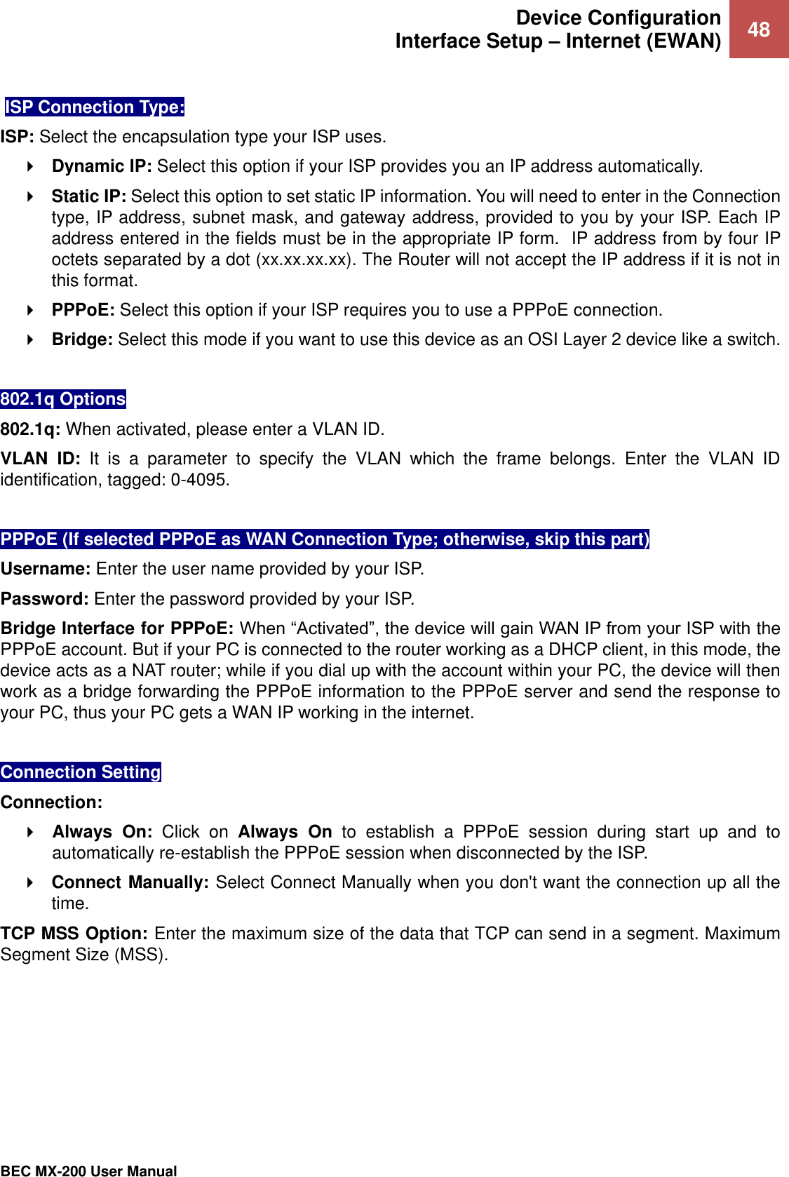
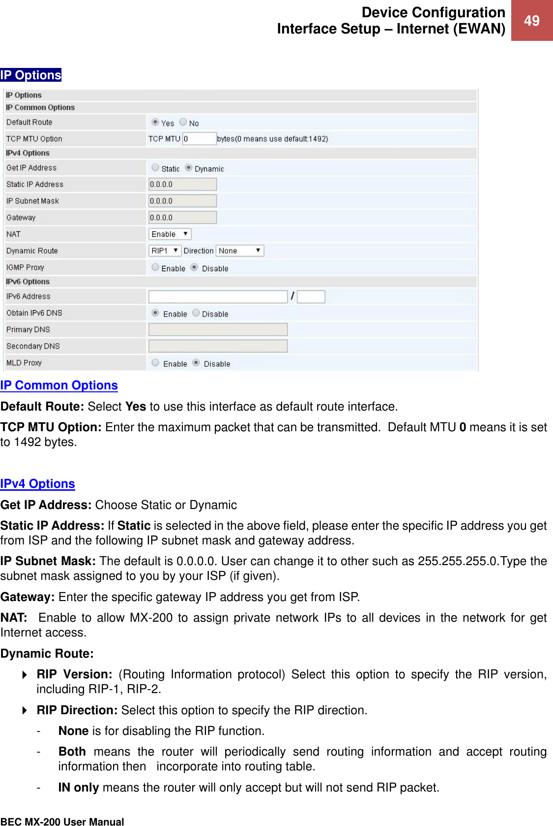
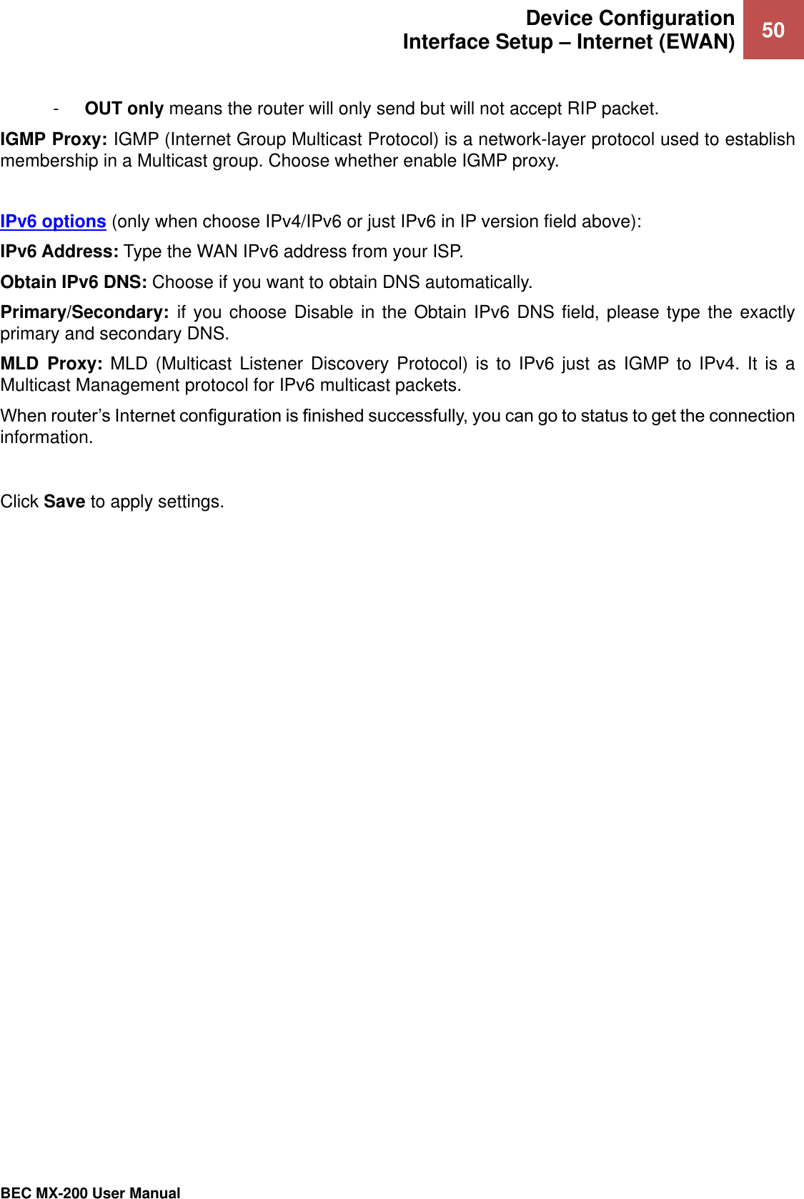
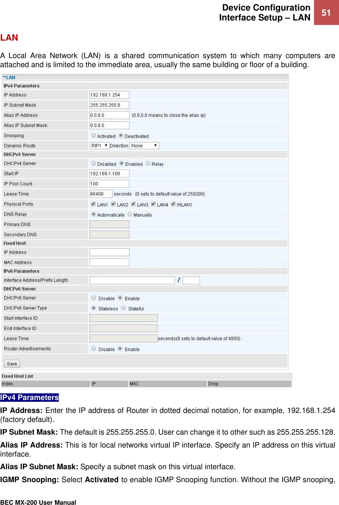
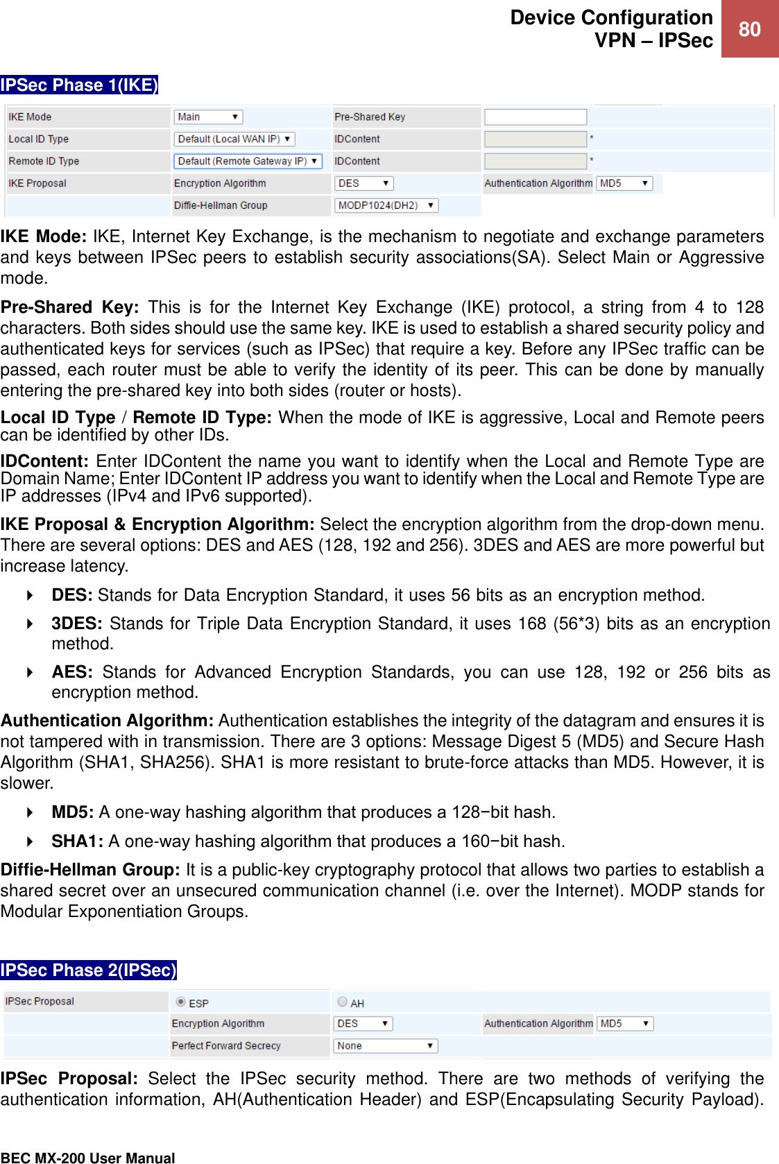
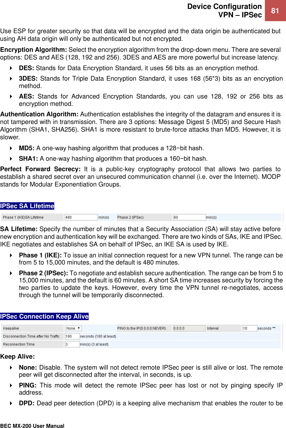
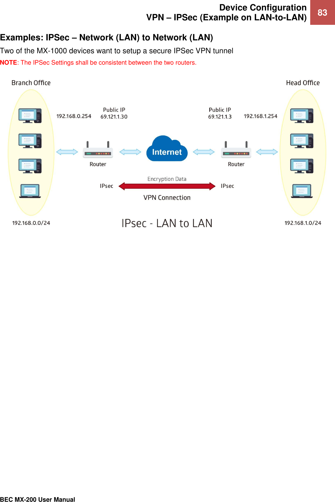
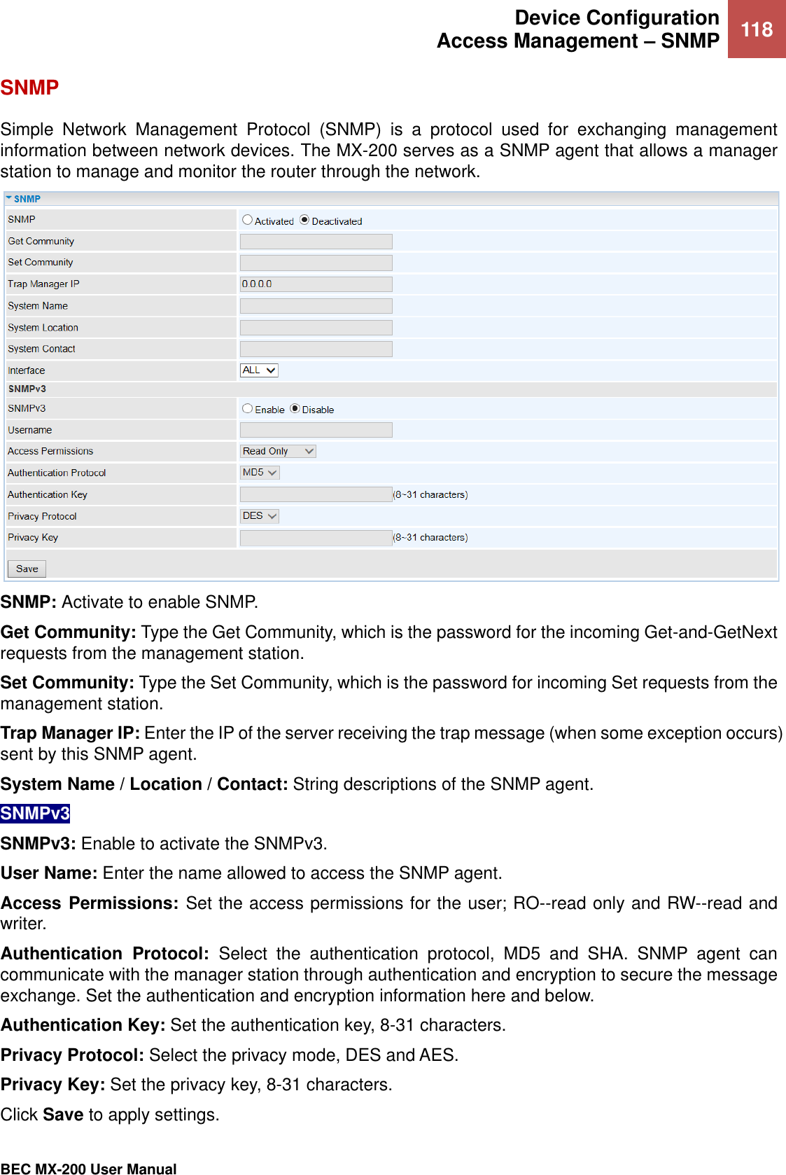
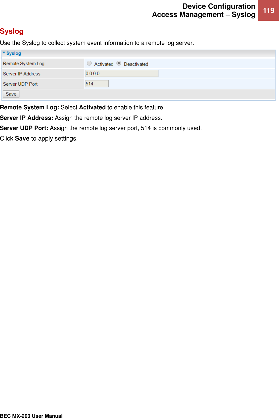
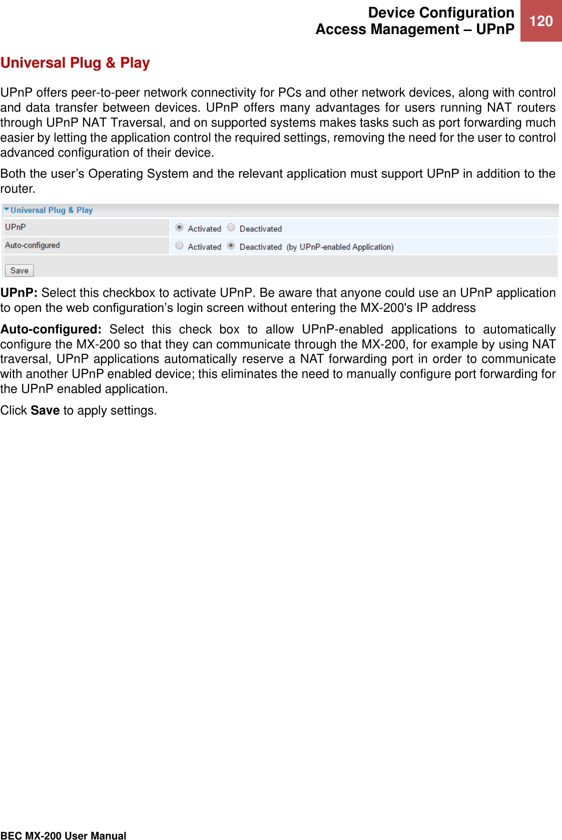
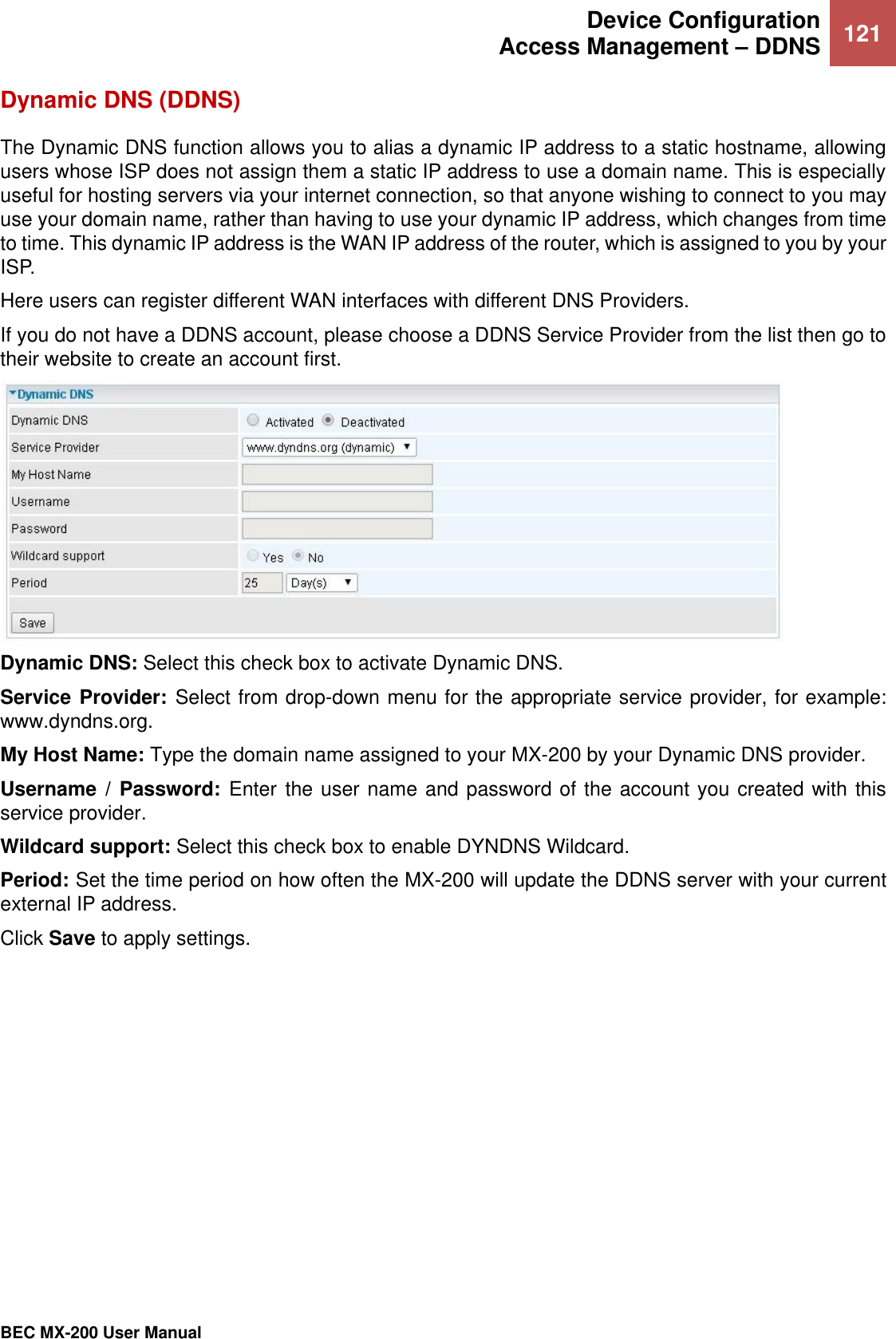
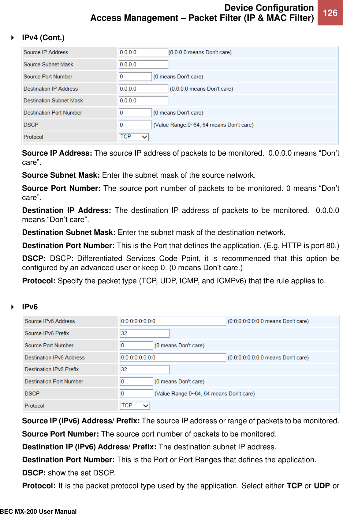
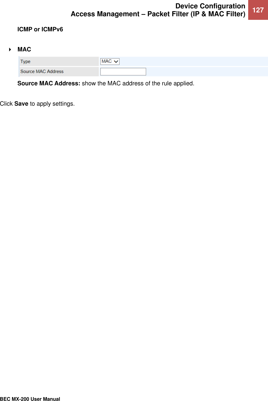
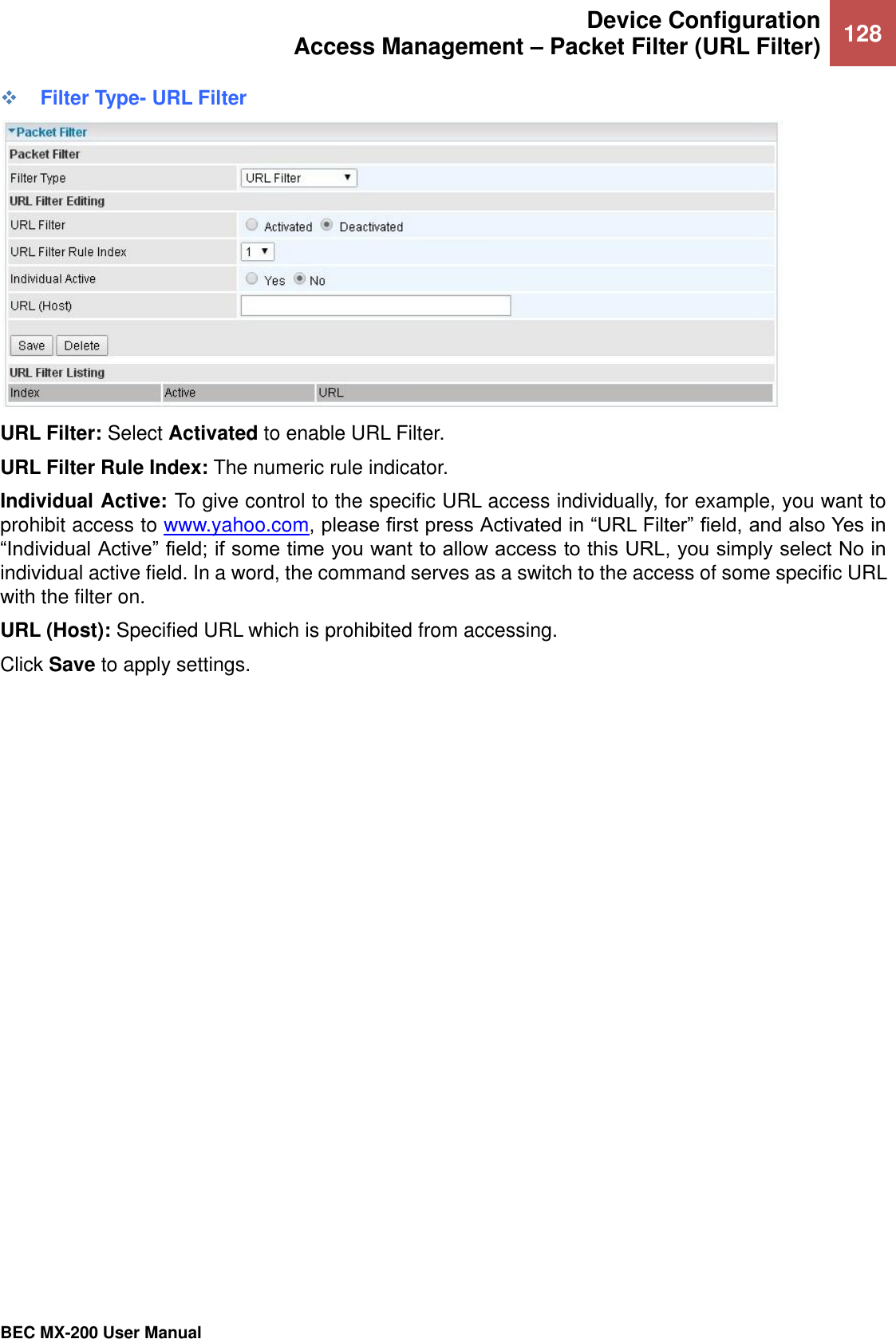
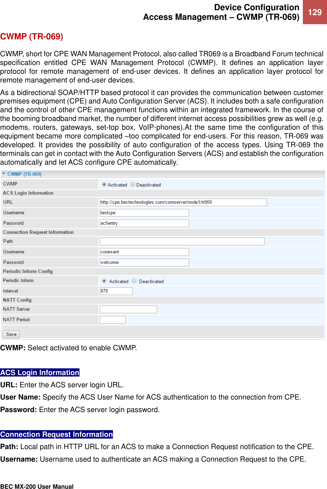
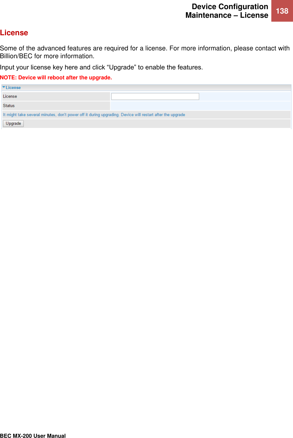
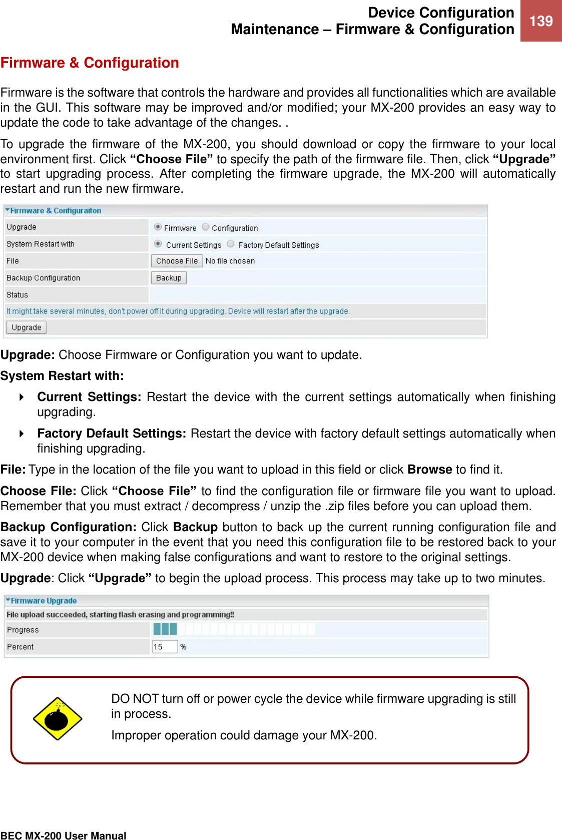
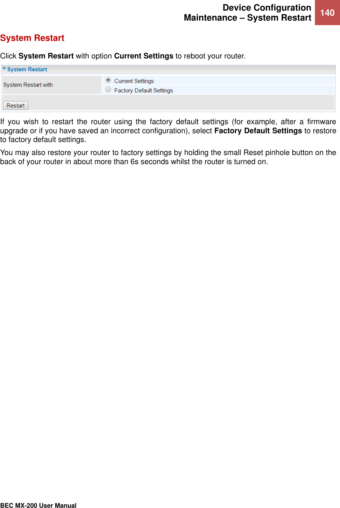
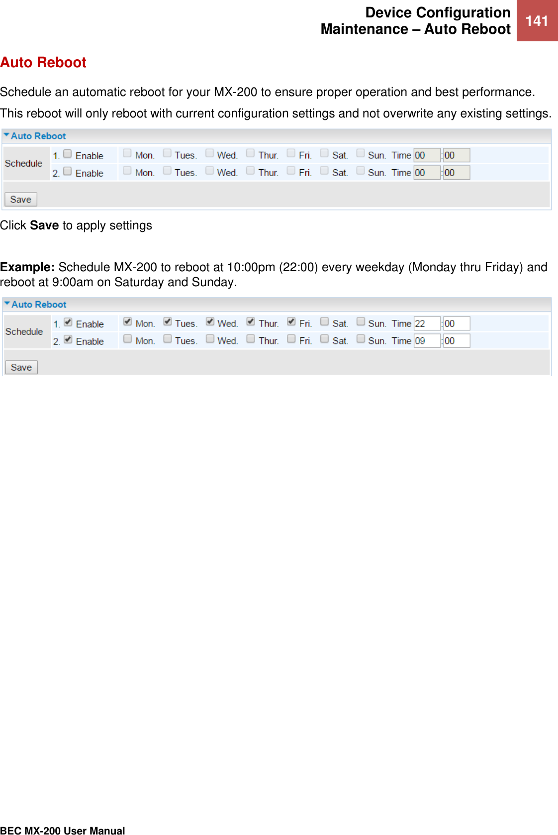
Billion Electric BIL-MX200A Advanced Industrial 4G/LTE Router, WWAN Failover Manager User Manual Product Overview
Billion Electric Co., Ltd. Advanced Industrial 4G/LTE Router, WWAN Failover Manager Product Overview
UserManual.wiki
>
Billion Electric
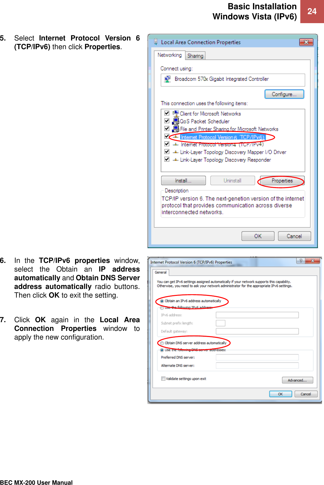
>
BIL MX200A User Manual
User Manual
Navigation menu
Upload a User Manual
Namespaces
Wiki Guide
HTML
PDF
Info
Views
User Manual
Discussion / Help
Navigation