Billion Electric BIL-SG600 Smart Energy Wireless Bridge User Manual
Billion Electric Co., Ltd. Smart Energy Wireless Bridge
user manual

Billion BEsmart Service Packages
SG600 Smart Wireless Bridge
User Manual
Last Revised on Mar. 2013
www.smartgrid.com.tw
Table of Contents
CHAPTER 1: Introduction ............................................................................. 0
1.1 Introduction of BEsmart ................................................................... 1
1.2 BEsmart Application......................................................................... 2
CHAPTER 2: Device Description and Installation ....................................... 3
2.1 BEsmart Package Content and Specifications .............................. 3
2.2 Device Descriptions ......................................................................... 5
2.3 BEsmart Installation ......................................................................... 7
2.3.1 Device Configurati .................................................................. 7
2.3.2 Network Configuration ........................................................... 9
2.3.3 Device Connections ............................................................. 23
2.3.4 Pairing the smart meter ........................................................ 25
2.3.5 Un-pairing the smart meter .................................................. 27
CHAPTER 3 Installation of Web Manager .................................................. 28
3.1 Quick Start .................................................................................. 28

WARNING
Federal Communication Commission Interference Statement
This equipment has been tested and found to comply with the limits for a Class B
digital device, pursuant to Part 15 of the FCC Rules. These limits are designed to
provide reasonable protection against harmful interference in a residential installation.
This equipment generates, uses, and can radiate radio frequency energy and, if not
installed and used in accordance with the instructions, may cause harmful
interference to radio communications. However, there is no guarantee that
interference will not occur in a particular installation. If this equipment does cause
harmful interference to radio or television reception, which can be determined by
turning the equipment off and on, the user is encouraged to try to correct the
interference by one or more of the following measures:
‧ Reorient or relocate the receiving antenna.
‧ Increase the separation between the equipment and receiver.
‧ Connect the equipment into an outlet on a circuit different from that to which the
receiver is connected.
‧ Consult the dealer or an experienced radio/TV technician for help.
FCC Caution:
This device complies with Part 15 of the FCC Rules. Operation is subject to the
following two conditions:
(1) This device may not cause harmful interference
(2) This device must accept any interference received, including interference that may
cause undesired operation. Any changes or modifications not expressly approved by
the party responsible for compliance could void the user's authority to operate this
equipment. . This device and its antenna(s) must not be co-located or operating in
conjunction with any other antenna or transmitter.
Co-location statement
This device and its antenna(s) must not be co-located or operating in conjunction
with any other antenna or transmitter.
FCC Radiation Exposure Statement
This equipment complies with FCC radiation exposure limits set forth for an
uncontrolled environment. This equipment should be installed and operated with
minimum distance 20cm between the radiator & your body.

1
CHAPTER 1
Introduction
1.1 Introduction of BEsmart
The issue of environmental protection and energy conservation has been
received great attentions since the global warming and energy shortage have
become a serious worldwide crisis. Billion BEsmart highlights the importance
of energy preservations and managements, and contributes smart solutions for
Telco/ISP/SI service providers who dedicate to strengthening customer
satisfactions. With the implement of the smart control, track, and monitor
power consumption technologies, energy usage could be clearly examined
and analyzed anytime and anywhere simply through a smart phone. It helps
reduce energy waste, provide a green environment, and further increase the
benefit of the mutual investment, that is, the investors and customers.
BEsmart brings a great amount of benefits with a long-term effect:
Increase Average Revenue, Increase Customers’ Satisfaction and Loyalty,
Reduce Customers’ Churn Rate, Leverage Existing Network Infrastructure,
Bring GREEN and Carry Out CSR. Furthermore, BEsmart also provides
effective power management, highly flexible on connection and establishment,
and extended applications on other services. Creating a win-win situation for
service providers and customers and establishing a green society are what
BEsmart expect to accomplish.
2
1.2 BEsmart Application
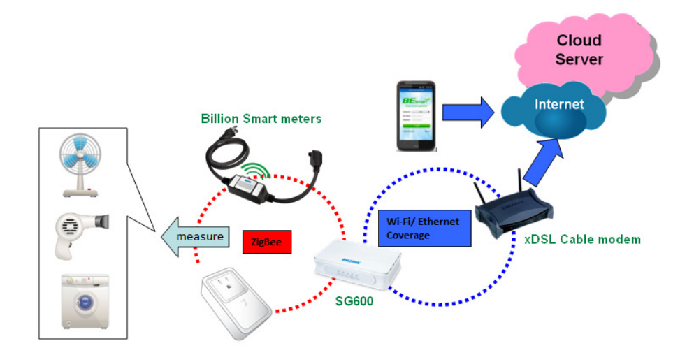
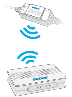
The SG600 acts the role of coordinator, which processes the power data
delivered from smart energy meters connected with electrical appliances by
ZigBee to an xDSL cable modem/router and then transmits to the cloud with
the internet access. All history information of power usage would be saved on
the cloud. BEsmart APP serves as a service platform for smart phone users to
make connection to the cloud server. Hence, users are able to monitor the
instant energy consumption status and review all the previous consumption
records. Furthermore, you can take control of power on/off status remotely for
the home appliances merely by a smart phone with an internet access.

3
CHAPTER 2
Device Description and Installation
This section specifies package contents, device descriptions, BEsmart kit
installations, and network connections.
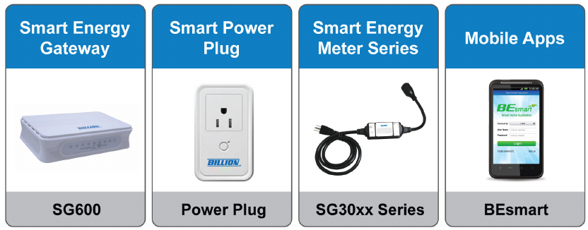
2.1 BEsmart Package Content and Specifications
§ SG600
Collect power information from each smart meter measure.
§ Smart Power Plug
Energy Management and Remote on/off Control
Comprehensive Measurement Capability
§ Smart Energy Meter
Remote power on/off control on connected electrical appliances
Electricity usage data and other indication information collection
§ Mobile App
Straightforward user interface (UI) for easy operation
Multiple functions all in a single glance on the main menu
4
5
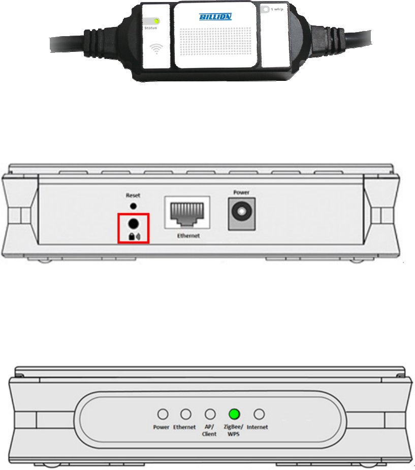
2.2 Device Descriptions
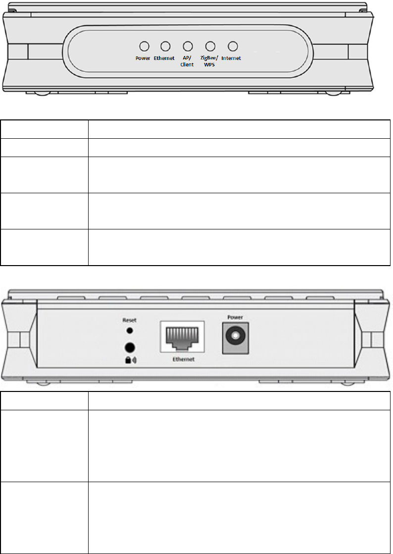
SG600 product overview
Power Lit green when power is ON
Ethernet Lit when one of LAN ports is connected to an Ethernet device.
AP/Client Lit green when wireless client is working
Blinking green when wireless client is not working
ZigBee/WPS Blinking green quickly when ZigBee pairing mode is working
Blinking orange quickly when WPS pairing mode is working
Internet Lit green when SG600 is getting internet connection
Lit red when wireless in not getting internet connection
Power Connect it with the supplied power adapter.
Reset
To be sure the device is being turned on press RESET button
for 6 seconds and above: restore to factory default settings.
Caution: After pressing the RESET button for more than
6 seconds, to be sure you power cycle the device again.
Ethernet
Connect a UTP Ethernet cable (Cat-5 or Cat-5e) to one of the
LAN ports when connecting to a PC or an office/home
network of
10Mbps or 100Mbps.
6
ZigBee/WPS
Push WPS button to trigger ZigBee function, thus smartmeter
allowing join in is starting. See ZigBee Config section.
Push WPS button more than 5 seconds to trigger Wi-Fi
Protected
Setup function. See WPS section.
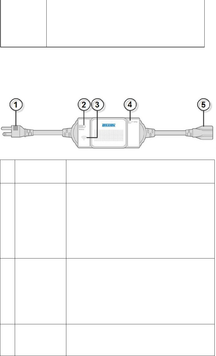
SG3015-T1/3010-T1
1
Power Plug
Put the plug in the power socket.
2
Status LED
Lit green when the meter does not pair with
SG6200NXL.
Blinking green when the meter is pairing.
Blinking green 5 time for 30 seconds when it reach
the strongest signal.
3
Power Meter
Setting Hidden
Button
When Status LED lights, press the hidden button for
3~5 seconds until the LED blinks, indicat
ing that the
device is connected to wireless network.
When Status LED blinks steadily, tap this button once
to detect the signal strength.
4
Energy Indicator
I
t would flash once when the electronic consumption
has accumulated to 1wh (0.001kwh).
7
5
Power outlet
Plug in the electronic
appliance that you intend to
monitor to the power outlet.
2.3 BEsmart Installation
It’s easy to setup the power meter and power plug simply by following the
instructions below. Also this section shows how the SG600 device connects to
the SG3010-T1/SG3015-T1.
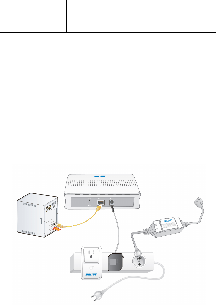
2.3.1 Device Configuration
The Illustration above demonstrates overall structure for device
configurations. To construct the connection environment, you must prepare a
PC, Billion SG600, a router, power meter(s), power plug(s), network
connection provided by ISP, and power supply. For the configuration, please
8
refer to the following instructions
SG600---Internet (Router)---PC
Connect a XDSL router to PC with an Ethernet cable and prepare your SG600
and connect it to the router with the supplied RJ45 Ethernet cable or wireless
client. Make sure the internet connection is workable (please refer to the next
Network Configuration section). You can configure the SG600 and manage the
power status through the web browser. For different internet environments,
please refer to internet setting document.
Electric Appliance----Power Meter
Plug in the electric appliance to the power meter or home plug and make sure
the power supply is on. Before managing the power information, you have to
pair the meter with the router. For the connection process, please refer to 2.3.3
for device connection.

9
2.3.2 Network Configuration
The router can be configured through your web browser. A web browser is
included as a standard application in the following operating systems: Linux,
Mac OS, Windows 98/NT/2000/XP/Me/Vista/7, etc. The product provides an
easy and user-friendly interface for configuration. Please check your PC
network components. The TCP/IP protocol stack and Ethernet network
adapter must be installed. If not, please refer to your Windows-related or other
operating system manuals.
There are ways to connect the router, either through an external repeater hub
or connect directly to your PCs. However, make sure that your PCs have an
Ethernet interface installed properly prior to connecting the router device. You
ought to configure your PCs to obtain an IP address through a DHCP server or
a fixed IP address that must be in the same subnet as the router. The default
IP address of the router is 10.10.10.252 and the subnet mask is 255.0.0.0 (i.e.
any attached PC must be in the same subnet, and have an IP address in the
range of 10.10.10.1 to 10.10.10.251). If you encounter any problem accessing
the router web interface it is advisable to uninstall your firewall program on
your PCs, as they can cause problems accessing the IP address of the router.
Users should make their own decisions on what is best to protect their network.
Please follow the following steps to configure your PC network environment.
10
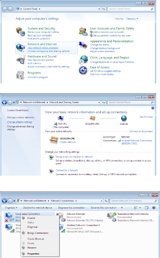
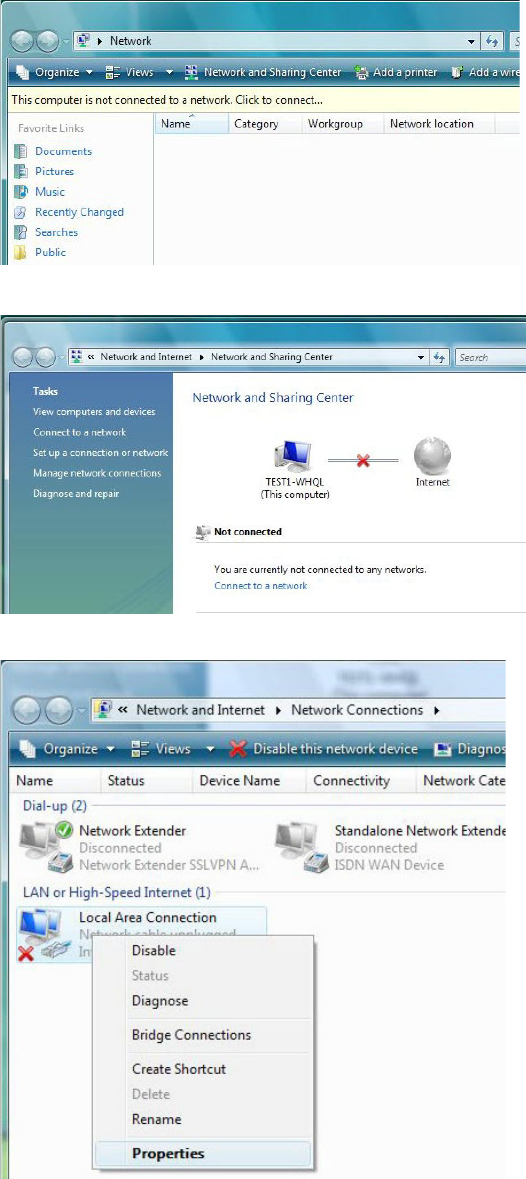
Configuring PC in Windows 7
1. Go to Start. Click on Control
Panel.
2. Then click on Network and
Internet.
3. When the Network and Sharing
Center window pops up, select
and click on Change adapter
settings on the left window
panel.
4. Select the Local Area
Connection, and right click the
icon to select Properties.
11
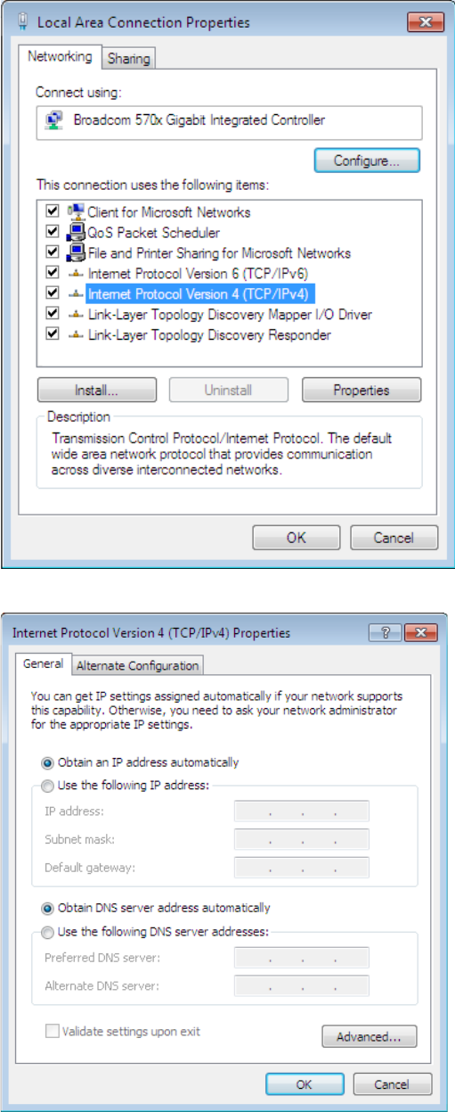
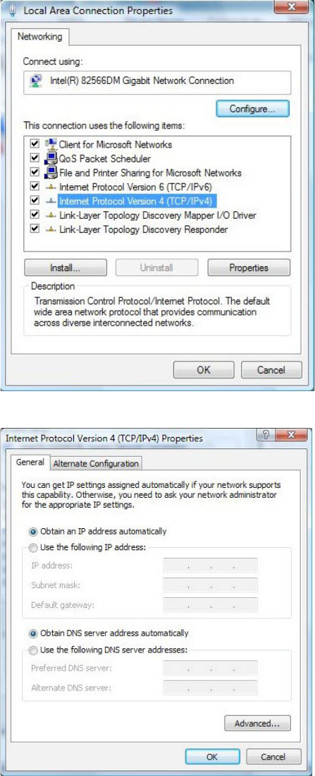
5. Select Internet Protocol Version
4 (TCP/IPv4) then click Properties.
6. In the TCP/IPv4 properties
window, select the Obtain an IP
address automatically and
Obtain DNS Server address
automatically radio buttons.
Then click OK to exit the setting.
7. Click OK again in the Local Area
Connection Properties window to
apply the new configuration.
12
Configuring PC in Window Vista
1. Go to Start. Click on Network.
2. Then click on Network and Sharing
Center at the top bar.
3. When the Network and Sharing
Center window pops up, select and
click on Manage network connections
on the left window column.
4. Select the Local Area Connection,
and right click the icon to select
Properties.
13
5. Select Internet Protocol Version 4
(TCP/IPv4) then click Properties.
6. In the TCP/IPv4 properties window,
select the Obtain an IP address
automatically and Obtain DNS
Server address automatically radio
buttons. Then click OK to exit the
setting.
7. Click OK again in the Local Area
Connection Properties window to
apply the new configuration.

14
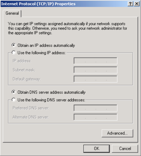
Configuring PC in Windows XP
1. Go to Start > Control Panel (in Classic
View). In the Control Panel, double-click
on Network Connections
2. Double-click Local Area Connection.
3. In the Local Area Connection Status
window, click Properties.
4. Select Internet Protocol (TCP/IP) and
click Properties.
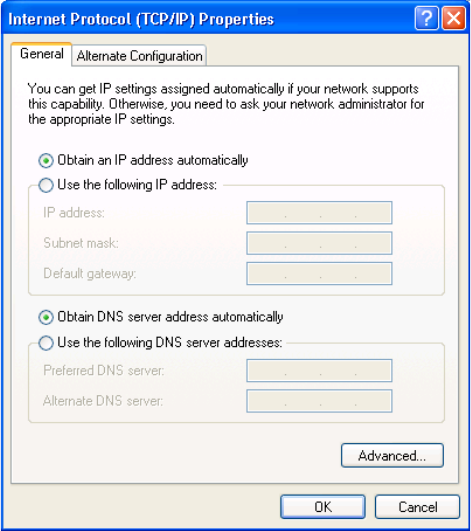
15
5. Select the Obtain an IP address
automatically and the Obtain DNS
server address automatically radio
buttons.
6. Click OK to finish the configuration.
16
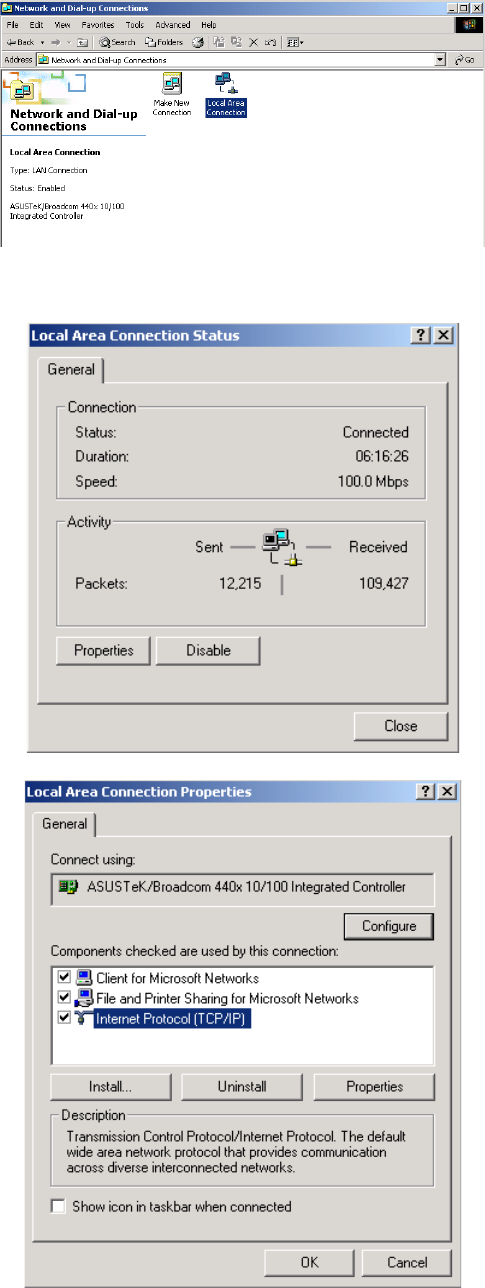
Configuring PC in Windows 2000
1. Go to Start > Settings > Control Panel.
In the Control Panel, double-click on
Network and Dial-up Connections.
2. Double-click Local Area Connection.
3. In the Local Area Connection Status
window click Properties.
4. Select Internet Protocol (TCP/IP) and
click Properties.
17
5. Select the Obtain an IP address
automatically and the Obtain DNS
server address automatically radio
buttons.
6. Click OK to finish the configuration.
18
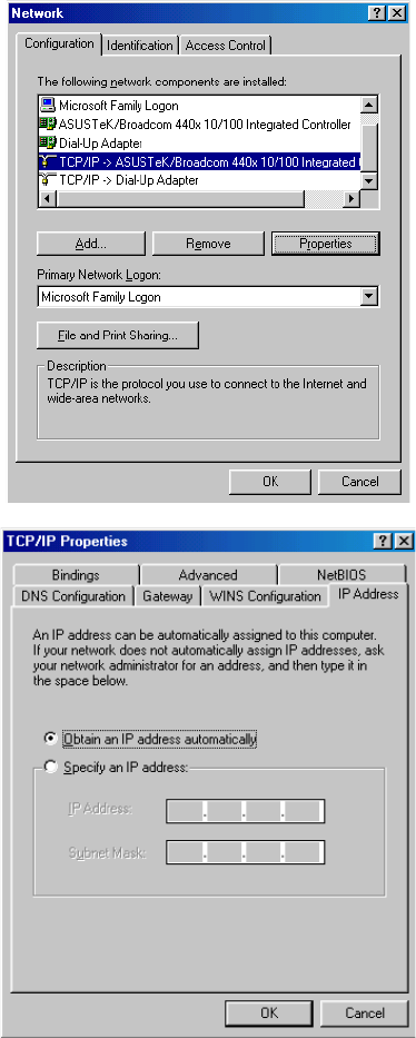
Configuring PC in Windows 95/98/Me
1. Go to Start > Settings > Control Panel.
In the Control Panel, double-click on
Network and choose the Configuration
tab.
2.
Select TCP/IP > NE2000 Compatible, or
the name of your Network Interface Card
(NIC) in your PC.
3. Select the Obtain an IP address
automatically radio button.
19
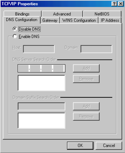
4. Then select the DNS Configurationtab.
Select the Disable DNS radio button and
click OK to finish the configuration.
5.
5. Select the Disable DNS radio button and
click OK to finish the configuration
20
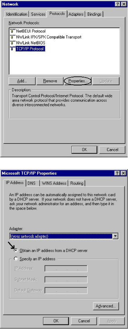
Configuring PC in Windows NT4.0
1. Go to Start > Settings > Control Panel.
In the Control Panel, double-click on
Network and choose the Protocols tab.
2. Select TCP/IP Protocol and click
Properties.
3. Select the Obtain an IP address from a
DHCP server radio button and click OK.

21
Factory Default Settings
Before configuring your router, you need to know the following default
settings.
Web Interface (Username and Password)
Username: admin
Password: admin
The default username and password are “admin” and “admin” respectively.
Device LAN IP settings
IP Address: 10.10.10.252
Subnet Mask: 255.0.0.0
22
Information from your ISP
Before configuring this device, you have to check with your ISP (Internet
Service Provider) to find out what kind of service is provided such as PPPoE,
Obtain an IP Address Automatically (DHCP), Fixed IP Address (Static IP).
Gather the information as illustrated in the following table and keep it for
reference.
PPPoE Username, Password, Service Name, and Domain Name
System (DNS) IP address (it can be automatically assigned
by your ISP when you connect or be set manually).
Obtain an IP Address Automatically
DHCP Client (it can be automatically assigned by your ISP
when you connect or be set manually).
Fixed IP Address IP address, Subnet mask, Gateway address, and Domain
Name System (DNS) IP address (it is fixed IP address).
23
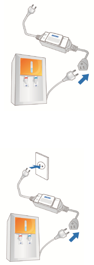
2.3.3 Device Connections
Step1: Plug in an electronic appliance that you intend to monitor to the power
meter.
Step2: Plug in the Power Meter to the wall outlet/socket.
Step3: Set up the connection between the power meter and SG6200NXL
(Please refer to Device Pairing section for detail)
24
NOTE: Please ensure that the power meter has been turned off or the
power supply has been cut off before setting up.
25
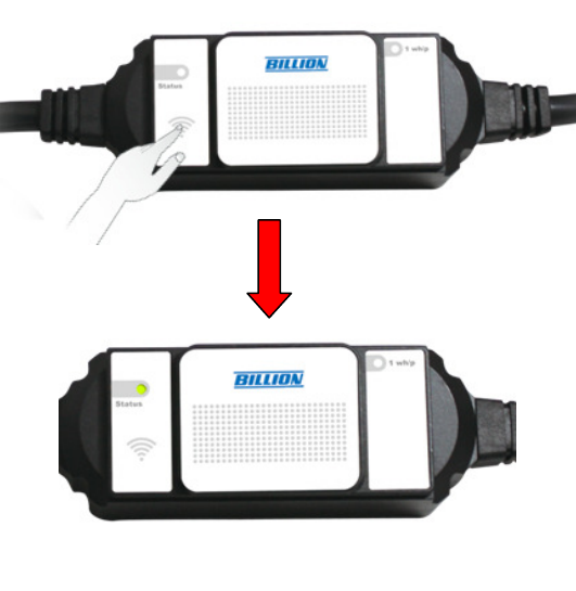
2.3.4 Pairing your smart meter
Step1: After setting up the power connections, please check if the status LED
light green before pairing.
Step 2: Push ZigBee button on the rear panel of SG600 to make a
connection.
Step 3: Then, ZigBee/WPS LED in the front panel will blink quickly around 30
seconds.
Step 3: Press the hidden button of the power meter until the Status LED blink
quickly with green light for few seconds. Then, the LED light would
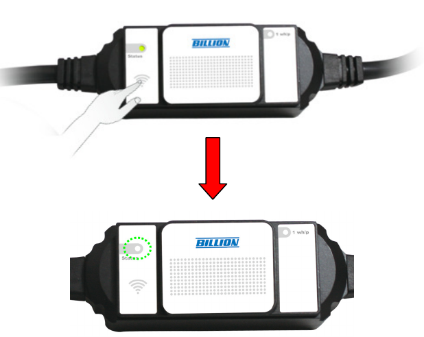
26
blink slowly and steadily, which indicates that the modem and the
power meter are successfully connected.
27
2.3.5 Un-pairing your smart meter
Before pairing the SG600 with smart power meters, please check if the
status LED lights green. If the status LED blinks green, it means that the meter
has been paired. Please un-pair the smart meter first then re-pair your own
ZigBee Gateway.
Step 1: Reboot your smart meter. You have 30 seconds to un-pair your smart
meter. Push hidden button of the power meter until the meter’s status LED
lights Green.
28
CHAPTER 3
Installation of Web Manager
The router not only functions as a smart wireless bridge but builds Power
Management Application into Web GUI. End users can monitor real time
power information and control the Smart Energy Meter through Web GUI
remotely. Please be noted that here we just focus on functions that are
relevant to the power smart management. Let’s start the configurations.
3.1 Quick Start
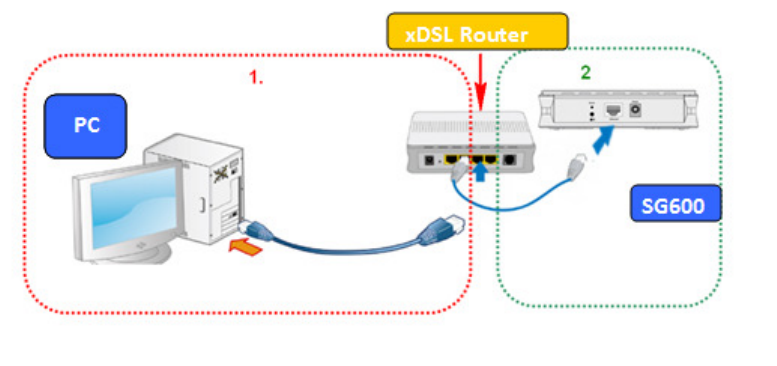
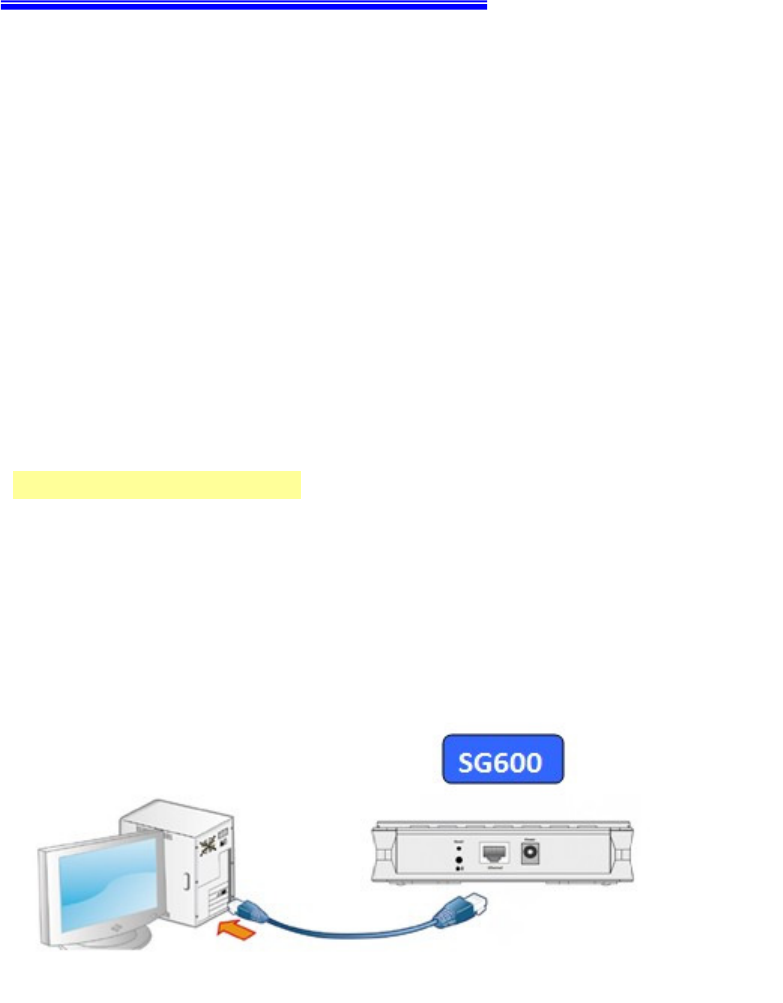
Step 1 : Hardware setting
Connect the SG600 to your PC’s Ethernet interface with supplied RJ-45
Ethernet cable and the other side to a router or modem with Ethernet cable or
wireless client for the internet connection.
29
Step 2: Computer IP setting
The default address of SG600 is 10.10.10.252. For the first setting, please
modify your PC IP to the recommended IP 10.10.10.100 (ranged from
10.10.10.1 to 10.10.10.251).
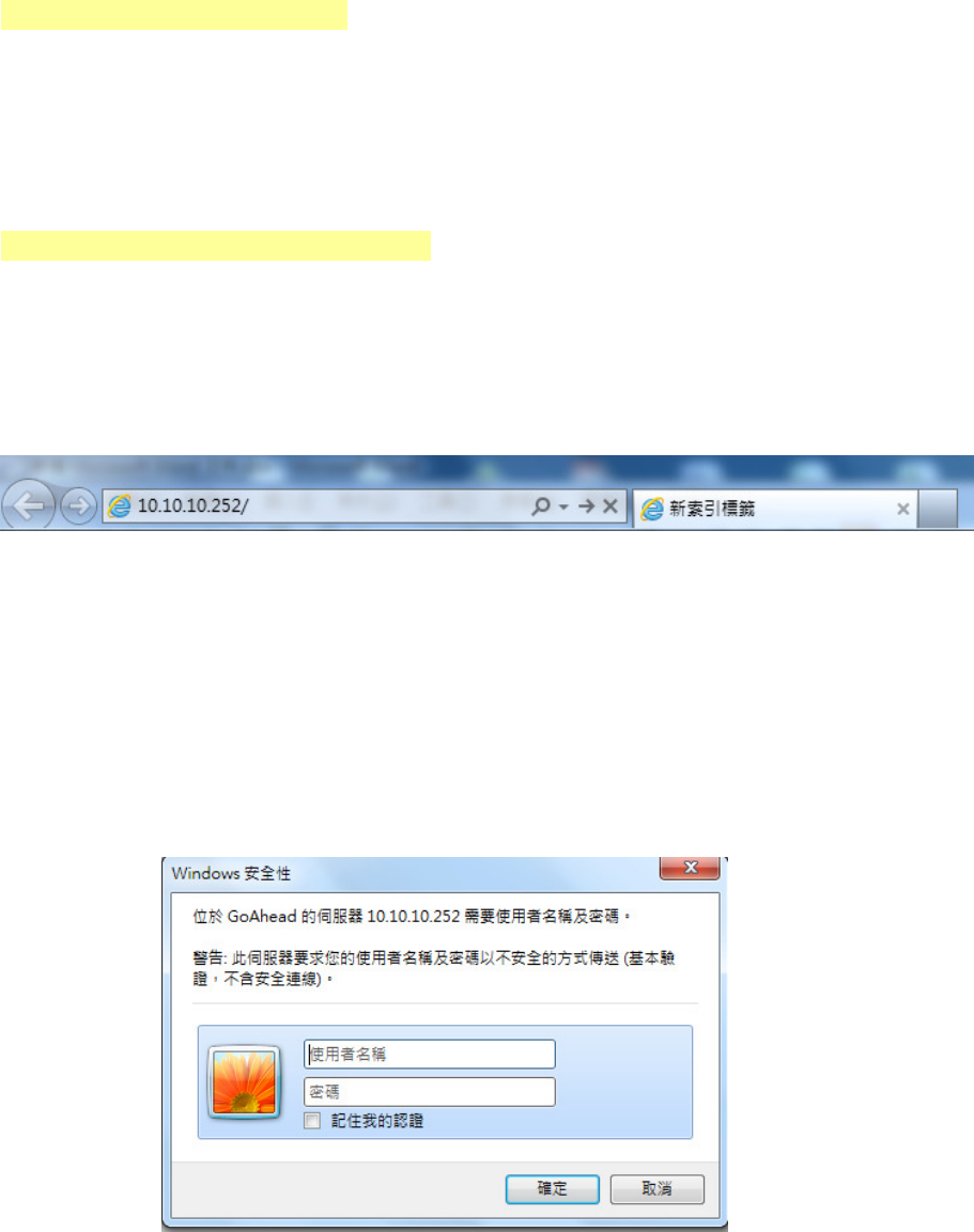
Step3: Access to SG600 WEB GUI
1. Open your web browser and enter the IP address of your router, which by
default is 10.10.10.252, and click “Go”. Then a login window prompt will
appear.
2. The default username and password are “admin” and “admin” respectively.
Choose “Administrator” from the account type to configure and manage the
web settings if your are authorized to access the router.
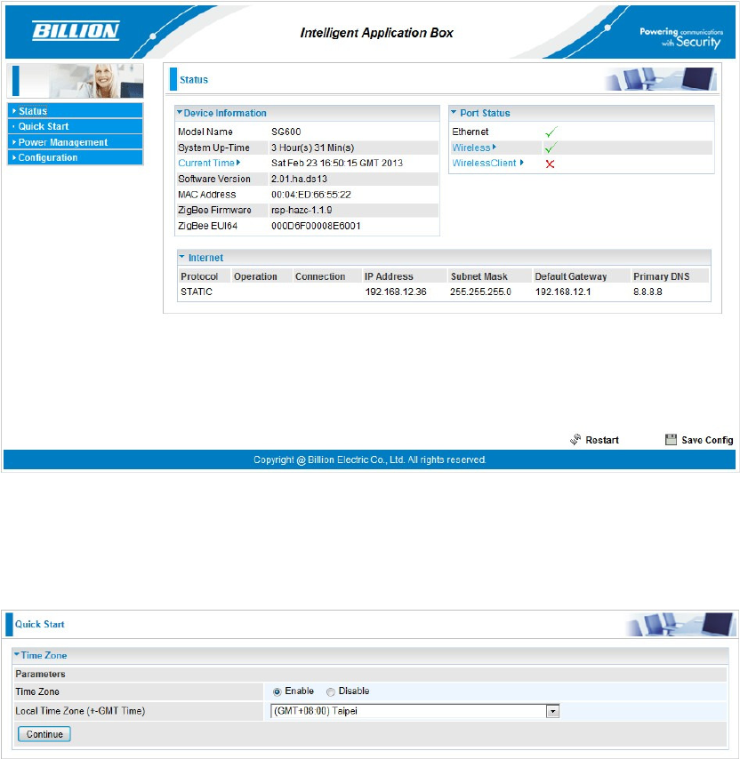
3. Once you have logged in to your SG600, you can begin to set it up
according to your requirements. You would see the main page of basic
status, including Device Information, Port Status, and WAN information.
30
4. Time Zone Setting
First, set up the time to meet the time zone of your country. Click “Continute”.
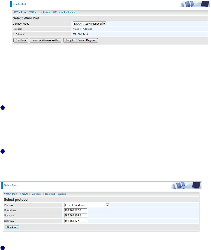
5. SG600 provides the WAN interface based on your own backbone router.
There are 2 Connect Modes: EWAN and Wireless Client.
EWAN: Your backbone router/cable modem is based on Ethernet base.
Wireless Client: Your backbone router or cable modem has the Wi-Fi
function.
For the detail Configuration, please refer to SG600 internet configuration
document.
31
6. There are 3 types of connection protocols available for WAN connect mode:
Obtain an IP Address Automatically, Fixed IP Address, and PPPoE
connection.
Obtain an IP Address Automatically (DHCP)
When connecting to the ISP, your router also functions as a DHCP client. That
is, your backbone device is xDSL router and your PC is assigned an IP
address automatically.
Fixed IP Address (STATIC IP)
Your backbone device is xDSL router and your PC IP is based on Static IP.
Enter the information provided by your ISP
PPPOE
If your backbone device is xDSL cable modem, please choose PPPOE.
For the detail internet configurations, please refer to SG600 internet settings.
Click “Continue” to proceed to the next step.
32
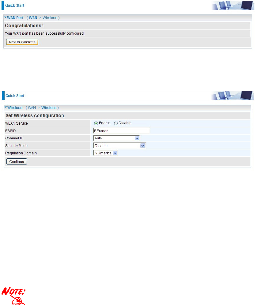
7.
To
set the Wireless configuration, click “Next to Wireless”.
8. Wireless setup
WLAN Service: Default setting is Enable.
ESSID: The ESSID is the unique name of a wireless access point (AP) to be
distinguished from another. For security propose, change to a unique
ID name to the AP which is already built-in to the router’s wireless
interface. It is case sensitive and must not excess 32 characters. Make
sure your wireless clients have exactly the ESSID as the device, in
order to get connected to your network.
ESSID is case sensitive and must not excess 32 characters.
Channel ID: Select the ID channel that you would like to use.
Security Mode: You can disable or enable with WPA or WEP for protecting
wireless network. The default mode of wireless security is
Disable.
Regulation Domain: There are seven Regulation Domains for you to choose
from, including North America (N.America), Europe, France, etc. The
33
Channel ID will be different based on this setting.
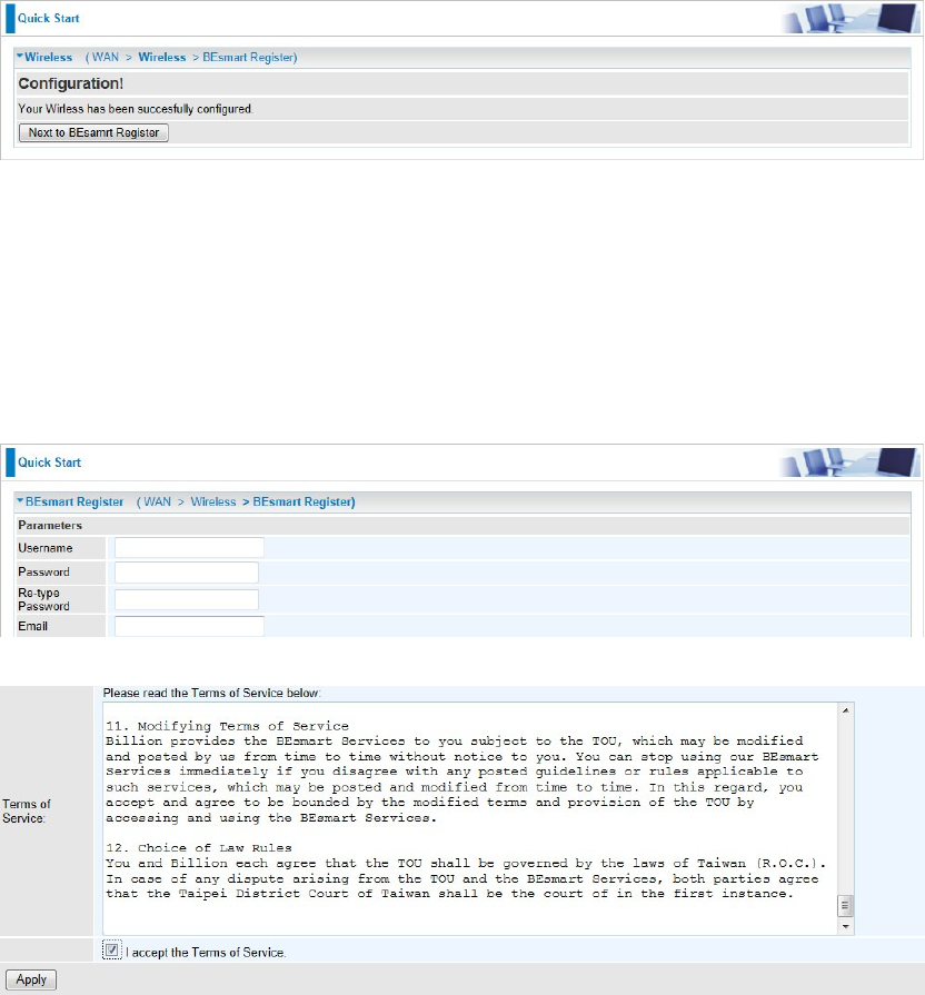
9. After clicking “Continue”, the program would start to save the settings. After
successfully saving the settings, you would be directed to BEsmart
Registration.
10. This is BEsmart Registration for cloud server. Create a username and
password and offer the E-mail for the registration, then read the term and
check the box “I accept the Term of Service”. Click “Apply” to confirm the
application.
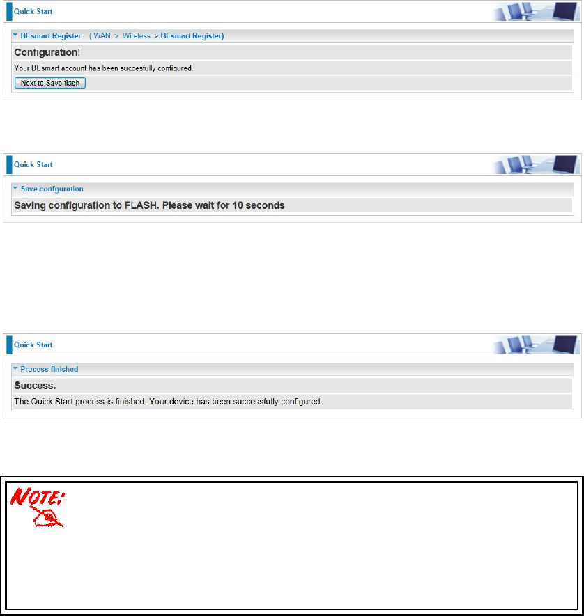
11. Congratulations! Your BEsmart cloud server has been successfully
registered. All the received power information would be stored on the cloud.
Click “Need to Save Flash” button to save your settings.
34
12. Please wait for 10 seconds for saving the configuration.
13. The easy configurations of your device have been finished.
Congratulations!
Please ensure that the smart wirele
ss bridge and its backbone
router/modem are maintained in a connection status or it may result in
different power consumption data between measurement and real
condition.
35