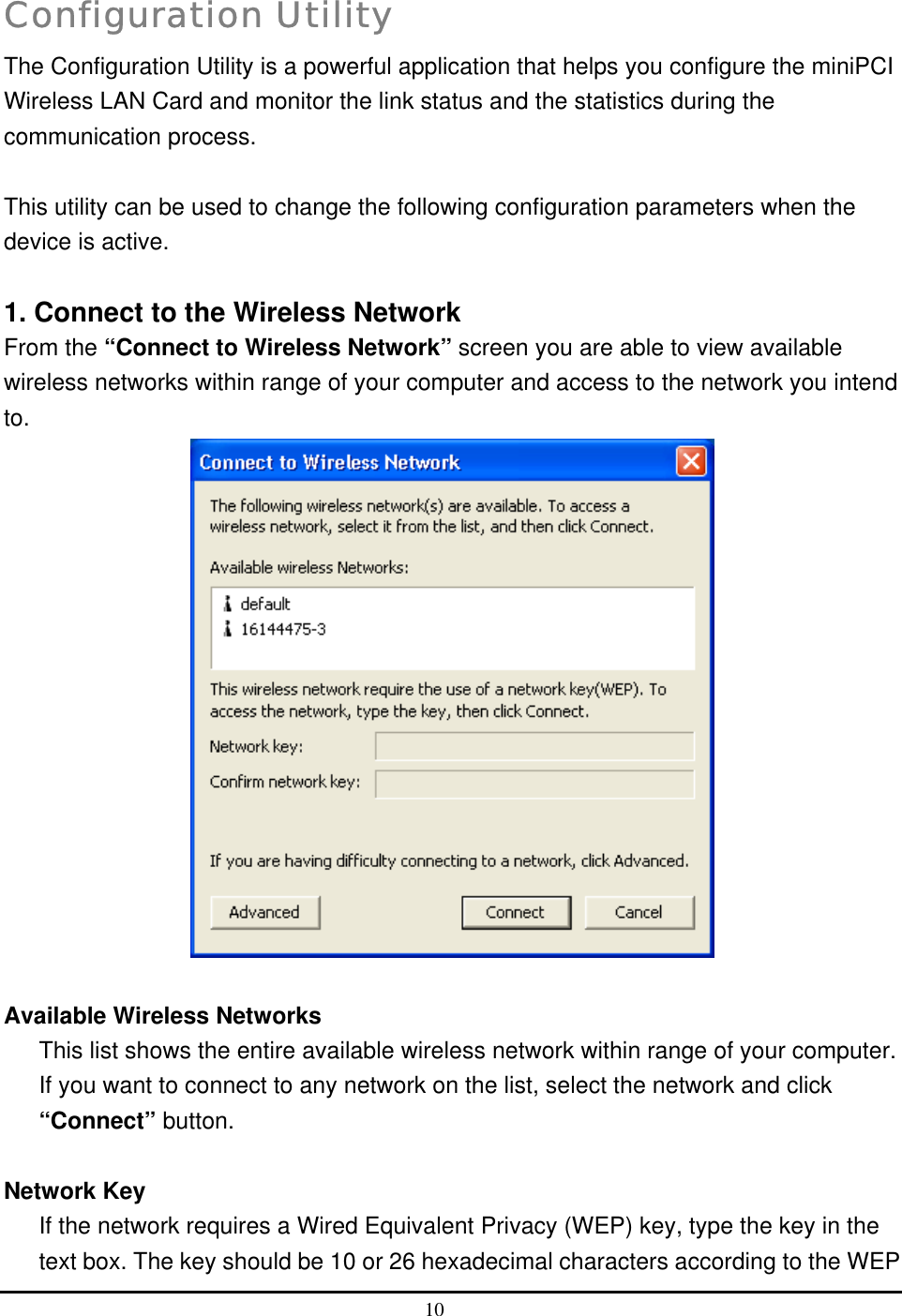
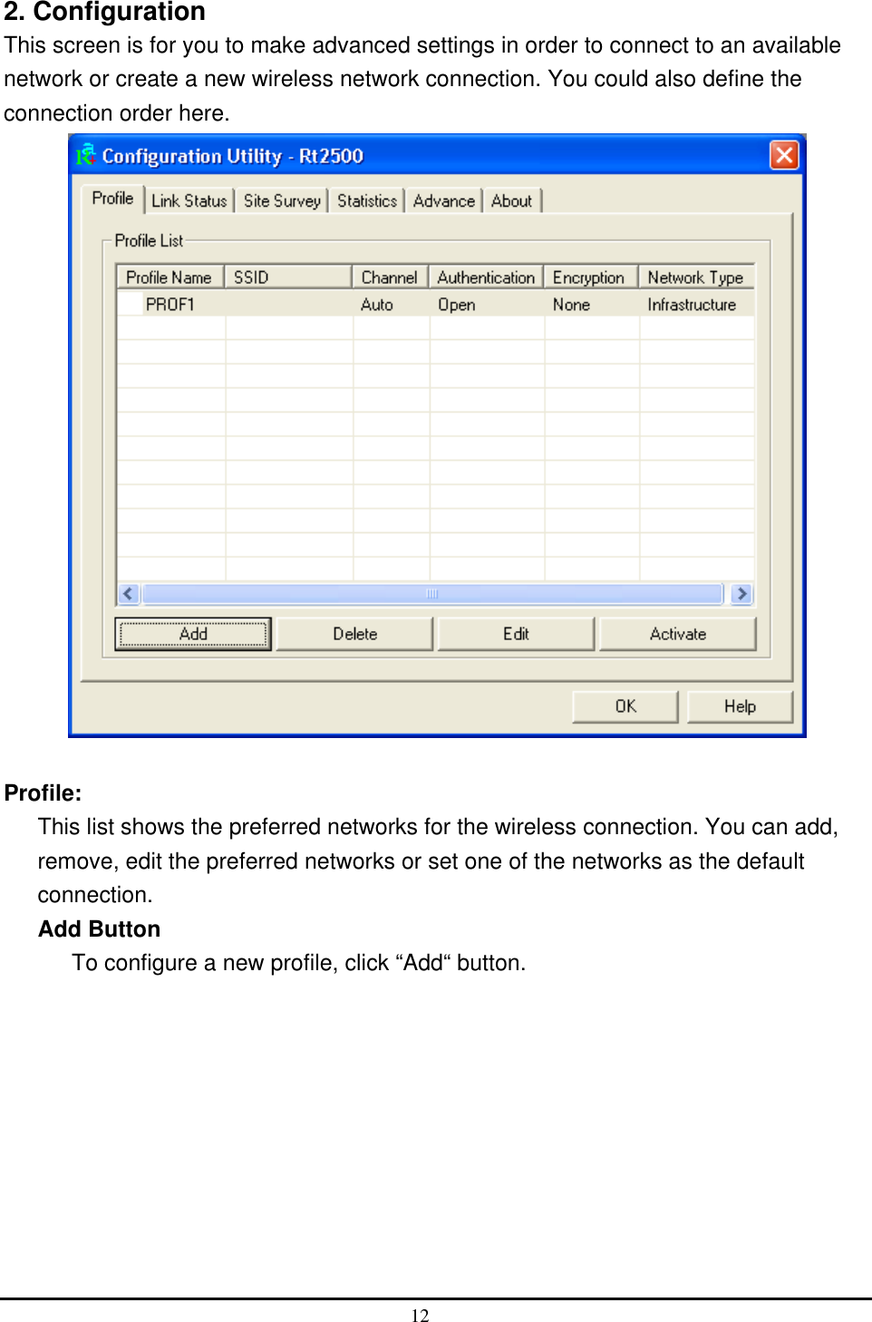
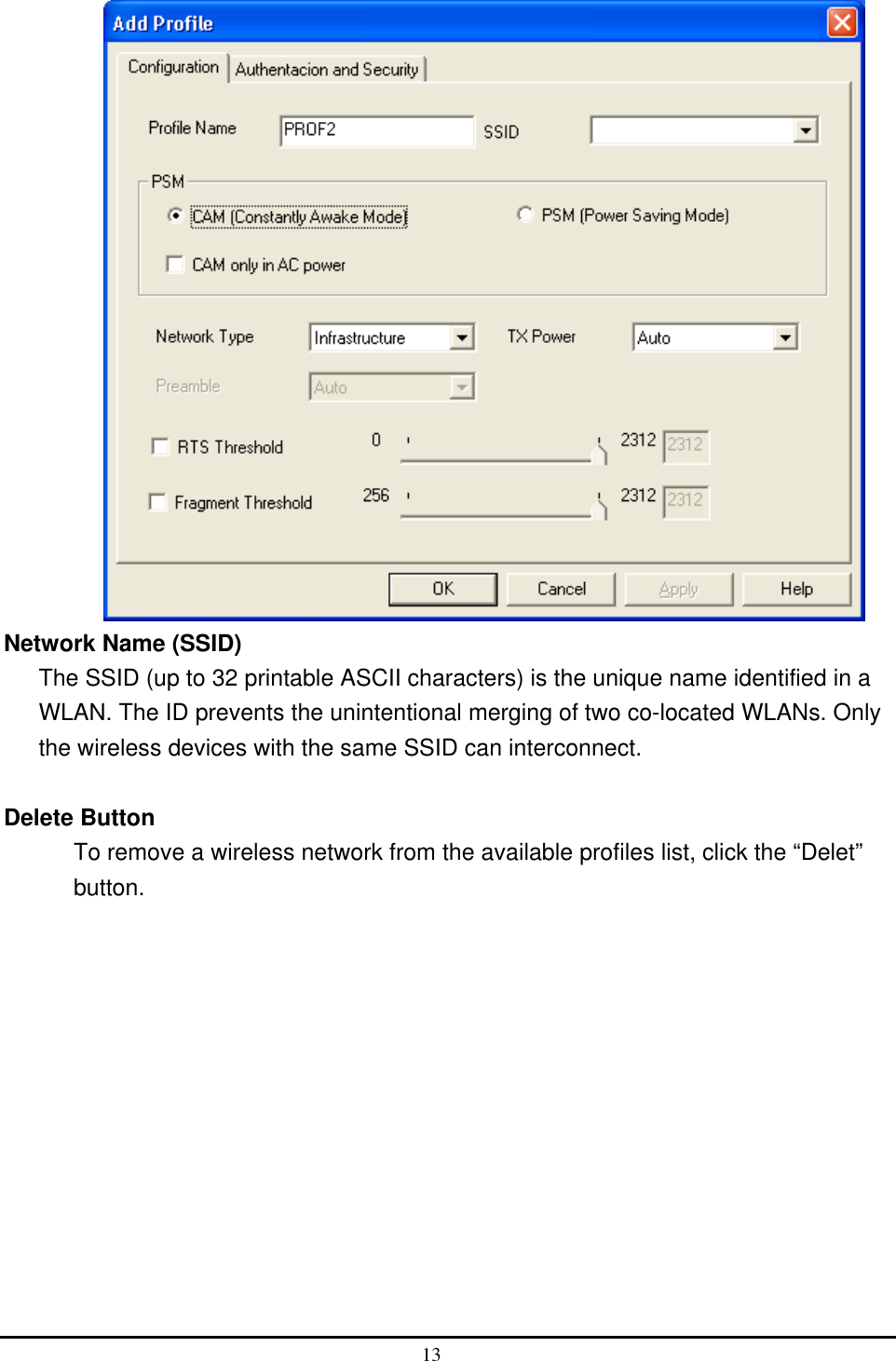
Billionton Systems GMIWLGRL2 WLAN IEEE802.11bg Module User Manual 1

Billionton Systems, Inc. WLAN IEEE802.11bg Module 1

Users Manual

MINIPCI WIRELESS LAN CARD           User’s Manual1.0
 Federal Communication Commission Interference Statement  This equipment has been tested and found to comply with the limits for a Class B digital device, pursuant to Part 15 of the FCC Rules. These limits are designed to provide reasonable protection against harmful interference in a residential installation. This equipment generates, uses and can radiate radio frequency energy and, if not installed and used in accordance with the instructions, may cause harmful interference to radio communications.  However, there is no guarantee that interference will not occur in a particular installation. If this equipment does cause harmful interference to radio or television reception, which can be determined by turning the equipment off and on, the user is encouraged to try to correct the interference by one of the following measures: - Reorient or relocate the receiving antenna. - Increase the separation between the equipment and receiver. - Connect the equipment into an outlet on a circuit different from that to which the receiver is connected. - Consult the dealer or an experienced radio/TV technician for help.  FCC Caution: To assure continued compliance, (example - use only shielded interface cables when connecting to computer or peripheral devices) any changes or modifications not expressly approved by the party responsible for compliance could void the user's authority to operate this equipment.  This device complies with Part 15 of the FCC Rules. Operation is subject to the following two conditions: (1) This device may not cause harmful interference. (2) This device must accept any interference received, including interference that may cause undesired operation.  IMPORTANT NOTE: This module is for OEM integrator. To comply with FCC RF exposure compliance requirements, the antenna used for this transmitter must be installed to provide a separation distance of at least 20 cm from all persons and must not be co-located or operating in conjunction with any other antenna or transmitter. This transmitter module must not be co-located or operating in conjunction with any other antenna or transmitter . The final end product must be labeled in a visible area with the following: "Contains TX FCC ID: NLFGMIWLGRL2"
 Industry Canada Statement   Operation is subject to the following two conditions: 1) This device may not cause interference and 2) This device must accept any interference, including interference that may cause undesired operation of the device This device has been designed to operate with an antenna having a maximum gain of 2.58 dBi. (Antenna gain) Antenna having a higher gain is strictly prohibited per regulations of Industry Canada.              The required antenna impedance is 50 ohms. To reduce potential radio interference to other users, the antenna type and its gain should be so chosen that the EIRP is not more than required for successful communication. To prevent radio interference to the licensed service, this device is intended to be operated indoors and away from windows to provide maximum shielding. (Equipment (or its transmit antenna) that is installed outdoors is subject to licensing).  Manual Information That Must be Included The OEM integrator has to be aware not to provide information to the end user regarding how to install or remove this RF module in the user’s manual of the end product which integrate this module. The users manual for OEM integrators must include the following information in a prominent location “ IMPORTANT NOTE: To comply with FCC RF exposure compliance requirements. The antenna must not be co-located or operating in conjunction with any other antenna or transmitter.
 Index Introduction 1 CHAPTER1 Specifications 2 CHAPTER2 Hardware Installation  4 CHAPTER3 Setup for Windows 98/2000/ME/XP  5 CHAPTER4 Troubleshooting 19
 1   i Introduction Thank you for purchasing this miniPCI Wireless LAN Card. This card is a wireless network client that complies with IEEE 802.11b/g standard on wireless LANs. The IEEE 802.11b/g standards compliance means this adapter gives you the flexibility to connect it to any 802.11g network. The IEEE 802.11b/g standard allows you to connect computers and devices at speeds up to 54Mbps, dependent upon the distance between wireless adapters, the configuration of your working environment, or the capabilities or limitations of your computer systems. Package contents •  One miniPCI Wireless LAN Card •  One CD (Driver/Utility/User’s Manual) NOTE: If any of these items are missing from the retail package, contact your supplier immediately.
 2   1 Specifications Features - Compatible with IEEE 802.11b/g Standard - 2.4GHz spread specturm technology - 54Mbps high speed transfer rate and backward compatible with 802.11b - Support antenna diversity - Support 64/128-bit WEP Data Encryption function for high level of security - Support WPA and AES advanced WLAN Security. - Supports peer to peer communication among any wireless users, no Access Point required - Support Quality of service(QOS)802.11e,WMM - Packet- OVERDRIVE technology - Software Range OVERDRIVE technology Specification 1. Interface:   - 32bit miniPCI V1.0   2. Mechanical   Dimension:  42.45 x 59.75 x 2.5mm (L x W x H) Function - Protocol : Compatible with IEEE 802.11b /g Standard - Modulation Technique : 802.11b:  DSSS (Direct Sequence Spread Spectrum) with BPSK (1Mbps), QPSK (2Mbps), and CCK (5.5 and 11Mbps) 802.11g: OFDM  - Transfer data rate : 802.11g : 54, 48,36,24, 18,12,9,6Mbps, auto-fallback                 802.11b : 11, 5.5, 2,1Mbps, auto-fallback   - Media access protocol : CSMA/CA with ACK - Antenna connection interface : Miniature coaxial Connector . - Output Power : 14~16dBm(CCK), 10~13dBm(OFDM) - RF sensitivity : @PER <0.08 ,11Mbps < -84dBm(typical)
                @ PER <0.08 ,54Mbps < -70dBm(typical) - Security : 64/128-bit WEP Encryption           64/128-bit TKIP Data Encryption             64/128-bit AES Data Encryption - Channels Support :                      US/Canada: 11 (1 ~ 11) Major European country: 13 (1 ~ 13) France: 4 (10 ~ 13) Japan: 14 (1~13 or 14th)  Environmental Operating Ranges   - Operating Temperature:  0 ~70° C,  Humidity   10 ~ 90%     - Storage Temperature:    -20 ~90° C,  Humidity   10 ~ 90%  Power Consumption - Maximum: Transmit    : 310mA (max),  Receive :   240mA (max)  -  Idle:  160 mA -  Green Certification RoSH-2002/95/EC  Certification FCC, CE class B,    Driver support Microsoft Windows 98SE / ME / 2000 / XP  3
 4   2 Hardware Installation 1.  Module is installed in the Personal Computer, located either under the keypad or on the bottom side of the Personal Computer (see the following diagrams).  2.  Antennas are embedded in the top corners of the panel (see the two circles shown below )
 5   3 Setup for Windows 98/2000/ME/XP 1.  Insert the CD into the CD-ROM device and execute the "setup.exe" program. The InstallShield Wizard box will appear, click "Next" to continue.                           2.  Follow the instruction of the installation program. The program will install the software for this device directly.
  3. Click "Finish" to complete the installation.  4.  When the Utility installation is completed, a new icon will display in the system tray 6
 at the bottom of the screen. Double click the shortcut or the icon to start using the miniPCI Wireless LAN Card.            In the system tray  Windows XP  Due to Windows XP has built-in wireless network utility you may decide to use the system’s utility or the one provided by this adapter. It is strongly recommended to use the utility of this adapter.  A. Using the Windows XP’s Utility Click the icon marked in red in the system tray and you may start using the Windows XP’s wireless utility.         B. Using the Utility of this adapter 1. Get into Windows XP’s Utility, click “Advanced“ button. 7
  2. On the “Wireless Networks“ tab in the “Wireless Network Connection Properties“ screen, clear the “Use Windows to configure my wireless network settings“ check box. If you want to enable the Windows XP built-in utility, select the check box again.  3. Double click the shortcut or the icon in the system tray and start using the miniPCI 8
 Wireless LAN Card.            Note: If you don’t disable the XP’s Utility, you can still see the link status and statistics during communication process from the adapter’s utility.  9
  Configuration Utility The Configuration Utility is a powerful application that helps you configure the miniPCI Wireless LAN Card and monitor the link status and the statistics during the communication process.  This utility can be used to change the following configuration parameters when the device is active.  1. Connect to the Wireless Network From the “Connect to Wireless Network” screen you are able to view available wireless networks within range of your computer and access to the network you intend to.   Available Wireless Networks This list shows the entire available wireless network within range of your computer. If you want to connect to any network on the list, select the network and click “Connect” button.  Network Key If the network requires a Wired Equivalent Privacy (WEP) key, type the key in the text box. The key should be 10 or 26 hexadecimal characters according to the WEP 10
 mode setting (64-bit or 128-bit) of the network.  Confirm Network Key Enter the same network key again to confirm the key.  Advanced Button To configure additional wireless network setting, review the link status and statistics or if you have difficulty connecting to a network, click “Advanced“ button.  Connect Button Click the button to connect to the selected network.  Cancel Button Click the button to cancel the wireless network connection. 11
 2. Configuration This screen is for you to make advanced settings in order to connect to an available network or create a new wireless network connection. You could also define the connection order here.   Profile: This list shows the preferred networks for the wireless connection. You can add, remove, edit the preferred networks or set one of the networks as the default connection. Add Button To configure a new profile, click “Add“ button. 12
  Network Name (SSID) The SSID (up to 32 printable ASCII characters) is the unique name identified in a WLAN. The ID prevents the unintentional merging of two co-located WLANs. Only the wireless devices with the same SSID can interconnect.  Delete Button To remove a wireless network from the available profiles list, click the “Delet” button.  13
   Link Status: Signal Strength This bar shows the signal strength level. The higher percentage shown in the bar, the more radio signal been received by the adapter. This indicator helps to find the proper position of the wireless device for quality network operation.  Signal Quality This bar indicates the quality of the link. The higher the percentage, the better the quality. 14
  Site Survey: It will show all available wireless Network(s) within range of your computer. You can double click the network listed in the table to make further configurations. Configure Button If you are unable to connect to an existing wireless network, click the network name and then click this button. The “Wireless Network Properties“ will show up for you to configure the adapter and ensure the settings are correct. Rescan Button To update the list of available networks, click the “Rescan“ button.  15
   Statistics You can get the real time information about the packet transmission and receiving status during wireless communication from the screen. If you want to recount the statistics value, please click “Reset Counter“ button.  16
  Advance This screen allows you to do some advanced configuration and some specific settings for the adapter.   Ad Hoc wireless mode Select the number of the radio channel used for the Ad Hoc networking. The channel of all the wireless stations in the Ad Hoc network should be the same. The parameter is not active in the infrastructure operation mode.  Note: The Infrastructure operation mode requires the presence of an 802.11 Access Point. All communication is done via the Access Point.  Turn Off RF   When the setting is checked, the wireless connection of the adapter will be disabled.   17
  About This screen displays the version and the designer of the Utility.    18
 19   4 Troubleshooting This chapter provides solutions to problems usually encountered during the installation and operation of the adapter.  1. What is the IEEE 802.11g standard? The IEEE 802.11g Wireless LAN standard subcommittee which formulates the standard for the industry. The objective is to enable wireless LAN hardware from different manufactures to communicate.  2. What does IEEE 802.11 feature support? The product supports the following IEEE 802.11 functions: •  CSMA/CA plus Acknowledge Protocol •  Multi-Channel Roaming •  Automatic Rate Selection •  RTS/CTS Feature •  Fragmentation •  Power Management  3. What is Ad-hoc? An Ad-hoc integrated wireless LAN is a group of computers, each has a Wireless LAN adapter, Connected as an independent wireless LAN. Ad hoc wireless LAN is applicable at a departmental scale for a branch or SOHO operation.  4. What is Infrastructure? An integrated wireless and wireless and wired LAN is called an Infrastructure configuration. Infrastructure is applicable to enterprise scale for wireless access to central database, or wireless application for mobile workers.  5. What is BSS ID?
 A specific Ad hoc LAN is called a Basic Service Set (BSS). Computers in a BSS must be configured with the same BSS ID.  6. What is WEP? WEP is Wired Equivalent Privacy, a data privacy mechanism based on a 40 bit shared key algorithm, as described in the IEEE 802 .11 standard.  7. What is TKIP? TKIP is a quick-fix method to quickly overcome the inherent weaknesses in WEP security, especially the reuse of encryption keys. TKIP is involved in the IEEE 802.11i WLAN security standard, and the specification might be officially released by early 2003.  8. What is AES? AES (Advanced Encryption Standard), a chip-based security, has been developed to ensure the highest degree of security and authenticity for digital information, wherever and however communicated or stored, while making more efficient use of hardware and/or software than previous encryption standards. It is also included in IEEE 802.11i standard. Compare with AES, TKIP is a temporary protocol for replacing WEP security until manufacturers implement AES at the hardware level.  9. What is IEEE 802.1x? 802.1x, an IEEE standard that provides an authentication framework for 802-based LANs. 802.1x will let wireless LANs scale by allowing centralized authentication of wireless users or stations. Based on the 802.1x framework, any wireless stations try to connect to the Access Point or Router should be authenticated by an Authentication Server.  The Authentication Server identifies the wireless station by a set of user name and password, only wireless stations provide correct user name and password can connect to the Access Point or Router and access to the network. 20
  10. Can Wireless products support printer sharing? Wireless products perform the same function as LAN products. Therefore, Wireless products can work with Netware, Windows 2000, or other LAN operating systems to support printer or file sharing.  11. Would the information be intercepted while transmitting on air? WLAN features two-fold protection in security. On the hardware side, as with Direct Sequence Spread Spectrum technology, it has the inherent security feature of scrambling. On the software side, WLAN series offer the encryption function (WEP) to enhance security and Access Control. Users can set it up depending upon their needs.  12. What is DSSS?What is FHSS?And what are their differences? Frequency-hopping spread-spectrum (FHSS) uses a narrowband carrier that changes frequency in a pattern that is known to both transmitter and receiver. Properly synchronized, the net effect is to maintain a single logical channel. To an unintended receiver, FHSS appears to be short-duration impulse noise. Direct-sequence spread spectrum (DSSS) generates a redundant bit pattern for each bit to be transmitted. This bit pattern is called a chip (or chipping code). The longer the chip is, the greater the probability that the original data can be recovered. Even if one or more bits in the chip are damaged during transmission, statistical techniques embedded in the radio can recover the original data without-the need for retransmission. To an unintended receiver, DSSS appears as low power wideband noise and is rejected (ignored) by most narrowband receivers.  21
 13. What is Spread Spectrum? Spread Spectrum technology is a wideband radio frequency technique developed by the military for use in reliable, secure, mission-critical communication systems. It is designed to trade off bandwidth efficiency for reliability, integrity, and security. In other words, more bandwidth is consumed than in the case of narrowband transmission, but the trade off produces a signal that is, in effect, louder and thus easier to detect, provided that the receiver knows the parameters of the spread-spectrum signal being broadcast. If a receiver is not tuned to the right frequency, a spread –spectrum signal looks like background noise. There are two main alternatives, Direct Sequence Spread Spectrum (DSSS) and Frequency Hopping Spread Spectrum (FHSS).  22

Navigation menu