Billionton Systems USBWLZ USB Wireless LAN Dangle User Manual USBWLZ Manual
Billionton Systems, Inc. USB Wireless LAN Dangle USBWLZ Manual
UserManual.wiki
>
Billionton Systems
>
USBWLZ User Manual
Users Manual
Navigation menu
Upload a User Manual
Namespaces
Wiki Guide
HTML
PDF
Info
Views
User Manual
Discussion / Help
Navigation
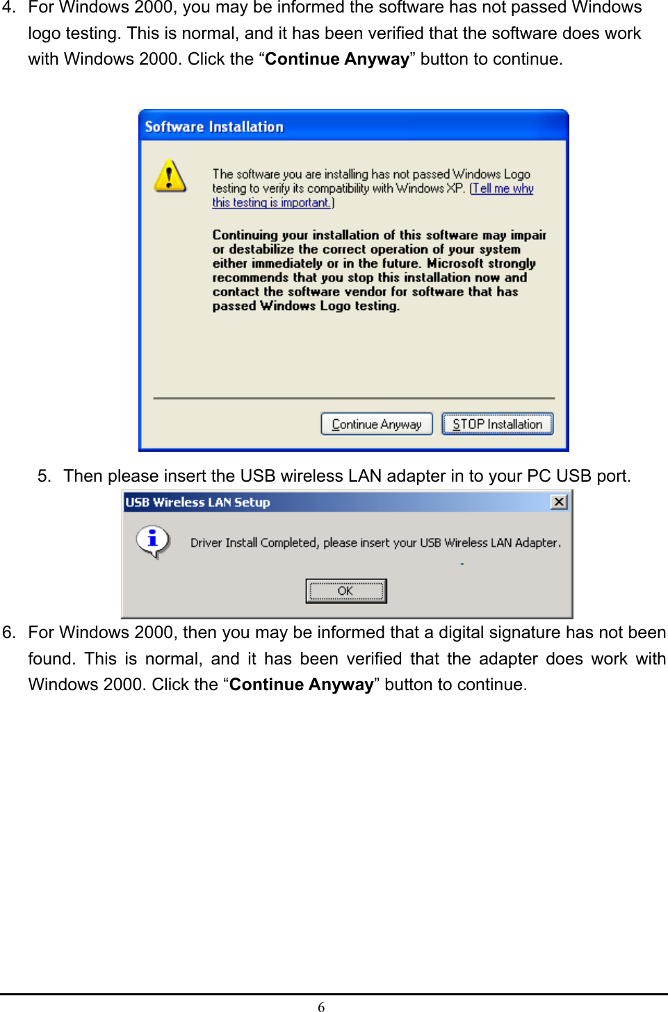
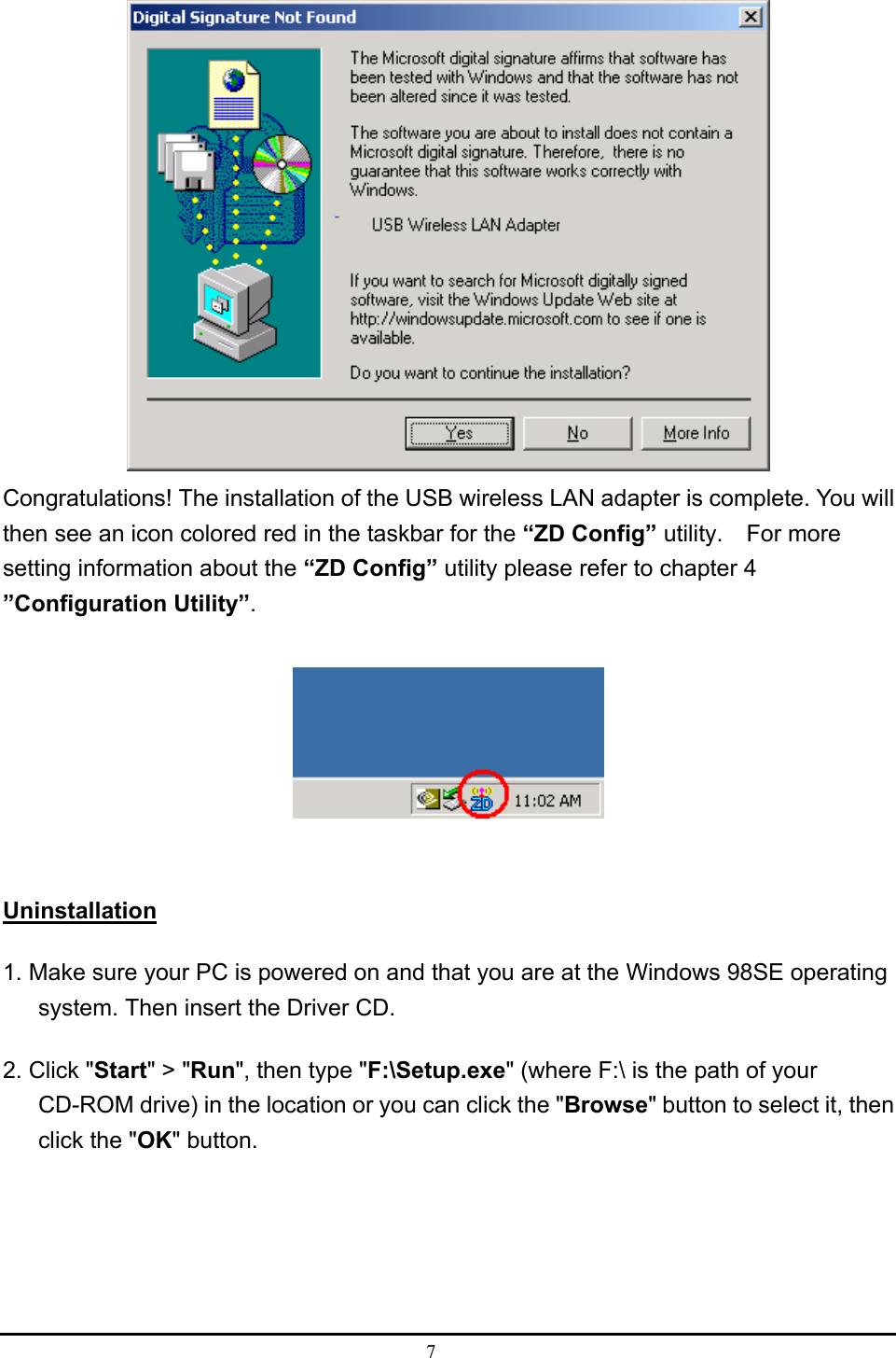
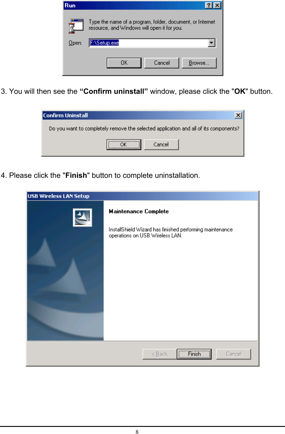
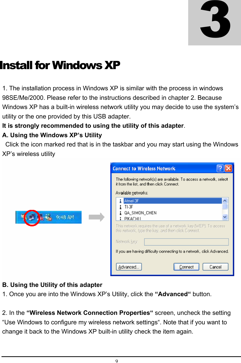
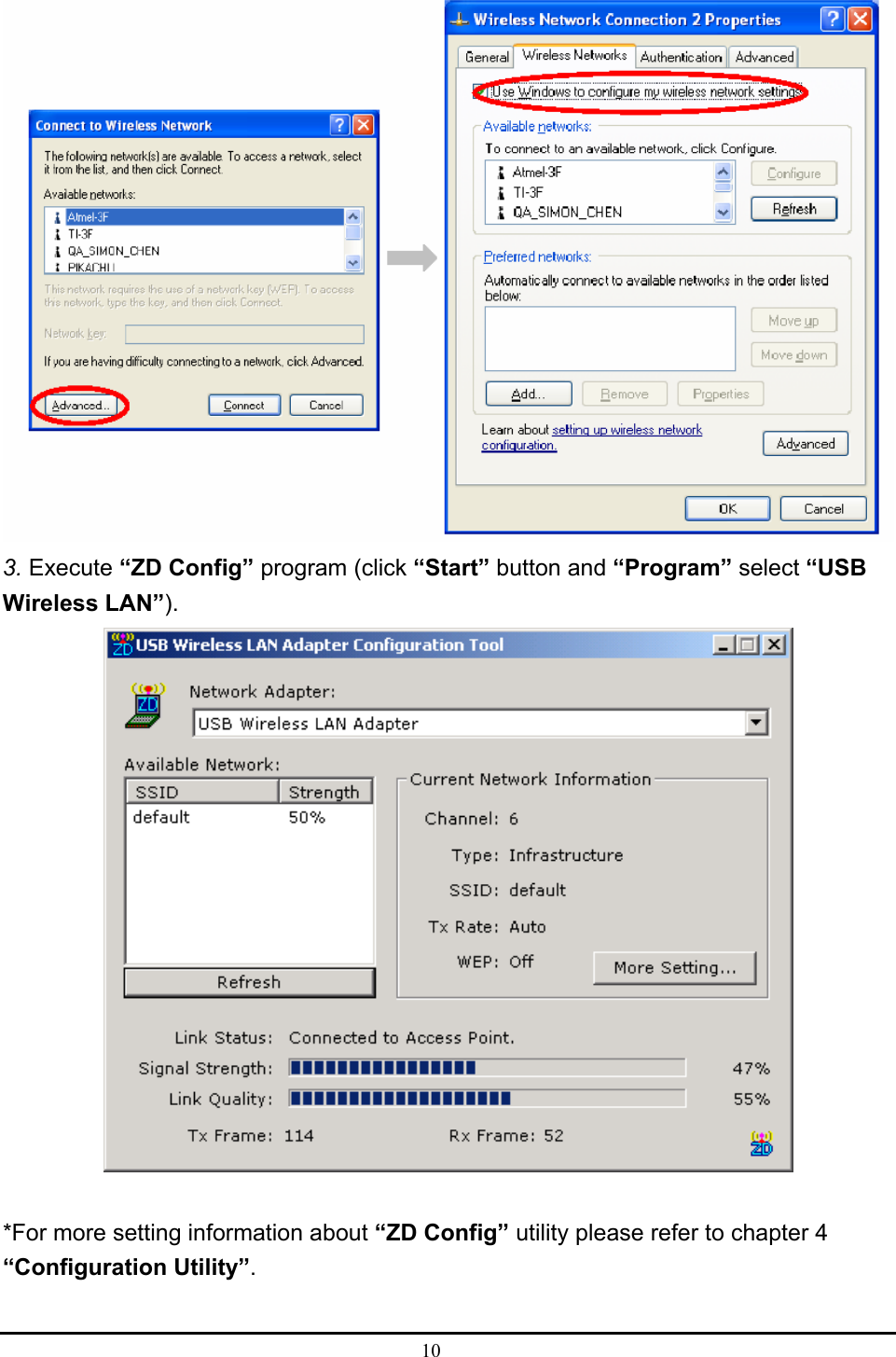
![5 3. Press [Next], to continue installation.](https://usermanual.wiki/Billionton-Systems/USBWLZ/User-Guide-385797-Page-9.png)