Billy Goat Sc120H Users Manual
SC120H to the manual e961a03c-6ad2-5ca4-fd97-3b8b29dbfa08
2015-02-02
: Billy-Goat Billy-Goat-Sc120H-Users-Manual-481512 billy-goat-sc120h-users-manual-481512 billy-goat pdf
Open the PDF directly: View PDF ![]() .
.
Page Count: 46
370310 F112003A
1
THANK YOU FOR SELECTING
THE POWERFUL BILLY GOAT SOD CUTTER
OPERATING AND SAFETY INSTRUCTIONS
MODEL: SC120H
SPECIFICATIONS
ENGINE: H.P. 5.5 (4.1 KW)
ENGINE: TYPE Gasoline, HONDA GX 160 K1
ENGINE: CAPACITY 5.5 hp (4.0 kW)
ENGINE: FUEL CAP. 3.0 qt. (2.84L)
ENGINE: OIL CAP. 0.66 qt. (0.6 L)
WEIGHT: UNIT 160.9 # (73 Kg)
MAX. ENGINE OPERATING SLOPE: 15°
UNIT SIZE: 30.7 in x 16.5 in x 24.0 in (0.78 m x 0.42 m x 0.61 m)
370310 F112003A
2
OPERATING AND SAFETY INSTRUCTIONS
SOD CUTTER MODEL-SC120H
FOREWORD
This machine may only be utilized for the purpose for which it was designed, i.e.
agricultural use, for the cutting of shoots, grass and brushwood.
Any other use other than that stated, not covered or deducible from this Manual
and the enclosed Engine Manual is "PROHIBITED".
Failure to comply with instructions in this Manual and in the Engine Manual re-
leases the manufacturer from all liability, in particular for any damage resulting
from improper or incorrect use, through negligence, superficial interpretation or fla-
grant disregard for the safety requirements herein.
Get your dealer to explain how to use the machine in optimum safety conditions.
Always perform the checks as prescribed herein before each work session with the
machine.
Should any information given in the following pages be unclear or not straightfor-
ward please contact the manufacturer directly.
1. USE OF THE MANUAL
This Manual consists of numbered pages and enclosures featured in the list of con-
tents.
Before operating the machine the user must read the instructions in the Operator's
Manual carefully as well as those of the Engine Manual enclosed.
Use of the sod cutter by more than one operator (individually), means that they
must have carefully read the Operator's Manual and the Engine Manual before us-
ing it.
The aforementioned manuals form an integral part of the machine and must there-
fore be kept intact and in good condition, in a known, easily accessible place for
the entire working life of the machine, even if the sod cutter is passed on to an-
other owner. The purpose of these manuals is to provide the information necessary
for the safe and competent use of the product. In the instance of wear or purely for
a greater technical working knowledge, the manufacturer may be contacted di-
rectly. The Notes Section at the end of the Sod cutter Manual is for the addition of
any complementary notes.
370310 F112003A
3
Contents of the SOD CUTTER Manual
1. Use of the Manual
2. Notices on the machine
3. Technical data
4. Lifting and transportation
5. Main parts of the machine
6. Controls and adjustments
7. Assembly instructions for the handlebars and end part of the cutting height
adjustment lever
8. Safety information
a) General instructions
b) Training
c) Preparation
d) Working use
e) Service brake checking
9. Transportation of the machine
10. Description of the safety systems and guards
11. Operations to be carried out before switching on
12. Starting and driving the sod cutter
13. Cutting tips
14. Checks
A) Tire pressure
B) Cable control adjustment
C) Belt replacement and adjustment
D) Checking and replacing the blade
E) Service brake checking
15. Maintenance and storage
16. Cleaning the machine
17. Seasonal long-term storage periods
18. Decommissioning and scrapping
19. Technical assistance
20. Warranty
21. Troubleshooting

370310 F112003A
4
2. NOTICES ON THE MACHINE
In this Manual all safety information appears in special boxes headed "WARNING".
WARNING
This heading is used to draw the user's attention to hazardous areas or moving parts of
the machine. It is also used in instances where failure to comply with the instructions
given may result in injury to persons and animals or damage to property.
WARNING
The Engine Exhaust from this product contains chemicals known
to the State of California to cause cancer, birth defects or other reproductive harm.
The symbols affixed to the machine serve to warn of danger during its use and
maintenance.
It is vitally important to understand the meaning of the danger notices and all mes-
sages should be kept in legible condition. In the instance of wear these notices
should be replaced and use of the machine suspended while without such notices.
The operator is advised to observe the warnings given on the affixed notices.
The symbols affixed to the machine serving to warn of danger during its use and
maintenance are as follows:
400268 – Label Hot Engine, Qty. 1
400424 – Label Warning, Qty. 2

370310 F112003A
5
370302 – Label Controls Instruction, Qty. 1
370300 – Label Instructions, Qty. 1
3. TECHNICAL DATA FOR THE SOD CUTTER SC120H
370310 F112003A
6
ENGINE : Gasoline, HONDA GX 160 K1
ENGINE CAPACITY : 5.5 hp (4.0 kW)
CUTTING WIDTH : 12” (30 cm)
CUTTING HEIGHT : adjustable up to 35 mm
SPEED GEARS : 1 forward gear - 1 reverse gear
TRANSMISSION : mechanical
GEARS : in oil bath
START : recoil
HEIGHT-ADJUSTABLE HANDLEBARS
TIRES : front tires = GARDEN 3.00-4
rear tires = GARDEN 4.10/3.50-4
DIMENSIONS L x W x H (mm) : 780 x 420 x 610 mm
WEIGHT (kg) : 73
ACOUSTIC PRESSURE, measured according to DIR.98/37/EC :86,2 dBA
ACOUSTIC POWER, measured according to ISO 374 : LWA 97,0 dBA
VIBRATION LEVEL TRANSMITTED TO THE HANDLEBAR ( EN 1033) AW = 7,8 m/s2
Environmental conditions
Unless otherwise stated at the time of ordering it is understood that the machine is
to work normally in the environmental conditions covered by the following points.
Environmental conditions other than those described may cause mechanical
breakage resulting in the creation of dangerous situations for persons.
A
LTITUDE
The altitude of the place in which the machine is to be used must not exceed 1500
m above sea level.
T
EMPERATURE
Minimum ambient temperature: -5°C
Maximum ambient temperature: +50°C
A
TMOSPHERIC CONDITIONS
The electrical equipment will function correctly in atmospheric conditions with a
relative humidity up to 50% at a temperature of 40°C and at 90% with a tempera-
ture up to 20°C (without condensate).
A
TMOSPHERE WITH RISK OF EXPLOSION AND/OR FIRE
The standard machine herein described is not designed to work in explosive at-
mospheres or in those with risk of fire.
4. LIFTING AND TRANSPORTATION

370310 F112003A
7
All material is carefully checked by the manufacturer before shipping. The sod
cutter is delivered in a cardboard box with the handlebars and end part of the
cutting height adjustment lever disassembled.
Upon receipt of the machine make sure that it has not been damaged during transit
and that the packaging has not been tampered or any parts removed. Report any
damage or missing parts immediately to the carrier and the manufacturer with
photographic documentation.
After assembling the handlebars and the end part of the cutting height adjustment
lever as per the instructions given in paragraph 7 of this manual, the machine may
be moved on its own wheels.
The manufacturer is not liable for any damage caused by transportation of the ma-
chine after its delivery.
WARNING
Extreme care must be taken during handling to prevent overturning. Avoid steep
gradients to prevent loss of control.
Make sure that there are no persons present within the danger area.
370310 F112003A
8
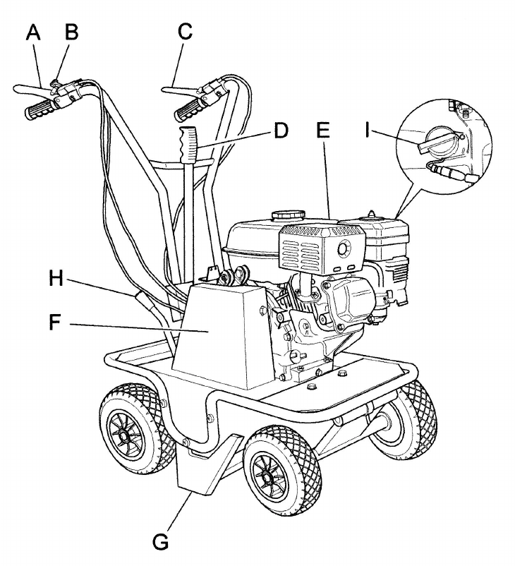
5. MAIN PARTS OF THE MACHINE
The machine consists of the following main parts
A – Blade clutch control lever
B – Accelerator control lever
C – Forward clutch control lever
D – Cutting height adjustment lever
E – GX 160 K1 engine
F – Cover
G – Blade
H – Forward -neutral-reverse gear selector lever
I – On/off switch (1/0)
Figure 1
370310 F112003A
9
6. CONTROL AND ADJUSTMENTS
A) BLADE CLUTCH CONTROL LEVER
This is used to engage and disengage the blade movement. Lowering the lever
engages the clutch and releasing it disengages the clutch.
WARNING
The blade will continue to move if the engine is running and the blade clutch is
engaged, regardless of the position of the forward clutch.
B) ACCELERATOR CONTROL LEVER
This is used to adjust the number of engine revolutions according to the operations
to be carried out. Hence at switch on the lever will be positioned on the minimum
setting whilst during work operations it will be positioned as required by use.
C)FORWARD CLUTCH CONTROL LEVER
This lever only has two positions: engage and disengage. Lowering the lever
engages the clutch and releasing it disengages the clutch.
This lever automatically operates the service brake: when released the lever
engages the brake, when engaged the lever disengages the brake.
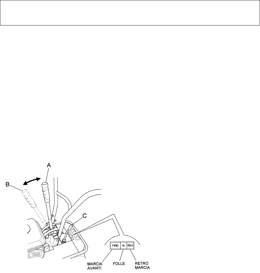
Fig. 2

370310 F112003A
10
D) CUTTING HEIGHT ADJUSTMENT LEVER
This lever serves to adjust the cutting height according to the type of terrain and
the thickness of the turf to be cut. (Fig.2 Ref. A)
F) COVER
The cover ( Fig. 1, ref. F) prevents any contact with the moving parts of the
machine. Use of the machine without the said cover is strictly prohibited.
I) ON SWITCH
Two-position switch:
(1)for starting the engine
(0 for switching off the engine
L) FORWARD-NEUTRAL-REVERSE GEAR SELECTOR LEVER
This lever selects the gear (forward, neutral, reverse).
WARNING : Select the required gear only after disengaging the forward clutch by
releasing the relative lever ( fig. 1, ref. C).
370310 F112003A
11
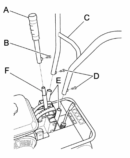
6. ASSEMBLY INSTRUCTIONS FOR THE HANDLEBARS AND END
PART OF THE CUTTING HEIGHT ADJUSTMENT LEVER
The sod cutter is delivered with the handlebars and the end part of the cutting
height adjustment lever disassembled. Remove the cardboard packaging (to be
disposed of in an appropriate manner, in accordance with current regulations in
force).
To assemble proceed as follows :
-Lift the handlebar (Fig. 3 Rif. C) and insert it in the supports shown in Fig. 3 rif. E.
Select the required cutting height and secure the setting using the screws provided
(Fig. 3 ref. D).
- Fit the end part of the cutting height adjustment lever (Fig. 3 Ref. A) into its
relative support (Fig. 3 ref. F) and secure using the screw provided (Fig. 3 Ref.B).
Fig. 3
Before switching on ensure that the machine has been fully assembled cor-
rectly.

370310 F112003A
12
8. SAFETY INFORMATION
Before using the sod cutter it is essential that the operator has understood the
warnings, do's and don'ts and precautionary measures given in this manual and in
the engine manual: the prevention of injury to the operator, third parties, animals or
objects directly depends on observance of these instructions.
A) GENERAL INSTRUCTIONS
! Use of the sod cutter for purposes other than those envisaged is strictly prohib-
ited.
! Climbing aboard and/or riding on the sod cutter is strictly prohibited.
! Tampering with the safety systems and guards is strictly prohibited.
! Modifications to devices/components not envisaged by the manufacturer are
strictly prohibited.
! The electrical parts of the engine must be protected at all times.
B)TRAINING
! Read the Operator's Manual and the Engine Manual before using the machine.
! Use of the machine by minors under the age of 16 years or by persons without
the necessary psychological and physical capabilities is forbidden.
! Do not use the machine near other persons or within enclosed areas.
! The placing of hands, other parts of the body and clothing in the moving parts
of the machine is prohibited.
! It is forbidden to approach the moving parts.
! Before carrying out any inspection or servicing operations make sure that the
engine has been switched off and the spark plug wire removed.
C) PREPARATION
! Make sure that the working area around the machine is free of obstacles and
has sufficient lighting.
! Before switching on the engine make sure there are no persons, animals or ve-
hicles in the vicinity .
! Before switching on the engine make sure that both engagement levers (for-
ward clutch control lever - Fig. 1, ref. C and blade clutch control lever - Fig. 1,
ref. A) Are in the disengaged position (released) ; then place the gear lever in
neutral (see Fig. 2, ref. C )
! Before switching on the machine make sure that the screws, fixing elements
and protection devices are in place and that the affixed notices are legible.
! Then: Make sure that the wheel fixing bolts have been tightened fully.
! Secure all blade nuts and fixing bolts to prevent their loss during work opera-
tions. Replace any old or worn blades.
! The cover ( Fig. 1, ref. F) should not be moved for any reason whatsoever
while the machine is in use.
! When switching on the engine check the position of the various control levers
(see the section on “Controls and adjustments”).

370310 F112003A
13
! Supervise the clothing of personnel operating the machine: a long-sleeved
jacket with close-fitting cuffs, long, close-fitting trousers, heavy-duty footwear,
and a protective cap or helmet should be worn. Avoid wearing loose-tailed
clothing, unbuttoned jackets or torn, undone or partially zipped up items to pre-
vent them from being caught up in the moving parts.
! Safety goggles and ear protection devices must be worn. Safety gloves must
also be worn during machine operation and maintenance.
! Do not switch on and operate the sod cutter in enclosed areas since the engine
gives off carbon monoxide fumes that are colourless, odourless, tasteless and
extremely dangerous.
! Take care when handling fuel. Fuel is highly flammable and its vapours explo-
sive:
- Only use an approved container
- Take care not to remove fuel caps or top up the tank with the engine running.
- Allow the engine to cool before proceeding with fuel-filling operations.
- Do not smoke during this operation.
- Never fill the machine with fuel in an indoor ambient
- It is advisable to use a wide funnel to prevent spillage of fuel on the engine
and on other surfaces of the sod cutter.
- If any fuel is spilled do not attempt to switch on the engine; simply move the
machine away from the area of spillage before switching on.
- After filling up with fuel reposition and screw the fuel tank cap right down.
• Do not rest the sod cutter or the fuel container in indoor environments with na-
ked flames
d) WORKING USE
! When working keep everyone at a minimum distance of 10 metres from the
machine.
! Keep the engine well ventilated and clog-free (materials and other residue) to
prevent damage to the engine and risk of fire. Clean the cooling fan and fins
regularly. Clean the air filter at the same time as well.
! Drive smoothly, avoiding brusque starts, braking and turns.
! Take care not to touch the silencer when hot.
! When reversing make sure there are no children or animals around. Take care
not to get caught up in the moving parts of the machine.
! If a slipping belt causes abnormal noise, smells or overheating, switch off the
engine immediately and check the machine to prevent the outbreak of fire and
damage to the transmission.
! The blade is extremely dangerous. Take great care during operation. Do not
use feet or hands to push the machine down into the turf and do not allow any-
one to stand either in front of the machine or in its direction of travel.
WARNING. During operation the lawn and turf are cut into strips. Should the cut-
ter’s wheels skid during use it is advisable to adjust the cutting height using the
special lever (Fig. 3, ref.A). If this operation does not prevent this occurrence check
the state of the terrain. If it is too dry it should be wetted so that the blade encoun-
ters a slight resistance, thus making cutting operations easier.

370310 F112003A
14
WARNING. When working in a stony or obstacle-riddled area try to remove as
many objects as possible before commencing cutting. Then work at a greater cut-
ting height than usual.
WARNING
Stones and other objects may be thrown outwards in direction of the opera-
tor or of other persons in the vicinity.
Keep at a safe distance from persons, animals and objects.
- If the cutting mechanism accidentally comes into contact with an object
(stump or stone), switch off the engine and carry out the following opera-
tions:
- Inspect the damage
- Do not attempt to repair it if unskilled to do so
- Check that no parts have come loose
! Do not use the machine if it does not work properly or is broken: seek author-
ized service.
! It is strictly prohibited to leave the sod cutter running whilst unsupervised.
! It is strictly prohibited to transport the machine with the engine running. When
loading the machine onto a vehicle, the inclination of the ramps must not ex-
ceed 15°.
WARNING!
EXERCISE CAUTION WITH GRADIENTS. Danger of machine overturning.
! Given its outdoor use, it is advisable not to use the sod cutter when it is raining.
! The area next to the engine exhaust may reach a high temperature.
WARNING!
Danger of burns.
! Do not go near water fountains or precipices and do not cross narrow bridges
during work operations to prevent the risk of falling.
! Do not work on steep banks
! In the instance of difficulty or emergency stop simply release the forward clutch
control and blade movement levers and return the gear lever to neutral position.
! Work on flat ground for the utmost safety.
E) AFTER USE
! Before moving away from the machine, place the gear lever in neutral (see fig-
ure 2, ref. C) and switch off the engine by moving the switch (Fig.1,ref.I) to the
0 position.
! For greater safety shut off the feed cock (Fig. 4).

370310 F112003A
15
9.TRANSPORTATION OF THE MACHINE
LOADING AND UNLOADING FROM A VEHICLE
! For transportation it is preferable to use a vehicle with an open bed.
! Choose firm, flat ground.
! Switch off the vehicle's ignition, put into reverse gear, pull on the hand brake
and block the tires with chocks to prevent accidental movement of the vehicle.
WARNING
Raise the blade to maximum height to prevent danger of its catching the ramp edges
! Do not stand in front of the machine
! Firmly hook the loading ramps onto the vehicle bed.
Use stable load ramps with a non-slip surface strong enough to take the weight
of the machine.
The inclination of the ramps must not exceed 15°.
Recommended length: at least 31/2 times the vehicle bed's height from the
ground.
Recommended width: to be chosen according to the tyre width of the machine
! Proceed with the loading of the machine, manoeuvring it carefully. Set the ac-
celerator lever at minimum (Fig. 1, ref. B) and using the lever as shown in figure
2, ref. C, engage the forward gear for loading, or the reverse gear for unloading.
! During loading/unloading operations on the ramps avoid operating the blade
clutch (Fig. 1, ref. A) And the gear lever (Fig. 1, ref. H) because such actions
may prove extremely dangerous.
! Line the front wheels up with the centre of the loading ramps.
! Take care when the machine passes from the loading ramps to the vehicle bed,
because a shift in balance occurs.
! Once loaded, turn off the engine using the relative switch (Fig. 1, ref. I), make
sure that the service brake has automatically come into operation upon release
of the forward clutch control lever (fig. 1, ref. C), block the machine wheels us-
ing chocks and firmly tie the machine to the vehicle.

370310 F112003A
16
10. DESCRIPTION OF THE SAFETY AND GUARD SYSTEMS
WARNING
The safety devices must never be tampered with. It is necessary to understand how they
work and safeguard their efficiency and correct operation. In the instance of doubt, prob-
lems or malfunction contact your dealer.
FORWARD CONTROL AND BLADE MOVEMENT LEVERS
When released both of these levers instantly disengage the transmission con-
nected to them.
In this way they act as safety devices.
In the instance of difficulty or sudden emergency, the quick release of these levers
will return them to their standard position (raised).
COVER
The cover ( Fig. 1 point F) partially protects the machine from any projected objects
and contact with the moving blade. Use of the machine without the said cover is
strictly probhited.
The cover should only be removed when replacing belts with the machine switched
off.
11. OPERATIONS TO BE CARRIED OUT BEFORE SWITCHING ON
Position the sod cutter outdoors on sufficiently firm, flat soil. Read the instructions
provided by the engine manufacturer in the relative manual and follow them care-
fully to prevent situations arising, which may endanger either persons or the ma-
chine
WARNING. NEW MACHINES STRAIGHT FROM THE FACTORY DO NOT
HAVE ANY ENGINE OIL!
Then check:
- The state of the blade by inspecting them;
- That all the screws are tightened, particularly those securing the blade;
- That the guards and safety devices are securely tightened.
- Before switching on the sod cutter make sure that there are no persons in the vi-
cinity.
- During operation do not allow persons near the machine, especially children. The
operator is responsible for any harm done persons in the working area of the ma-
chine.
Oil recommendations
The engine is supplied without oil. Before starting up the engine fill with oil and
check the oil level with the engine in a horizontal position. Do not overfill.
Use of high-grade detergent oil is recommended (refer to the enclosed engine
manual).
Fuel recommendations
Use of fresh, clean lead-free petrol is advised.
WARNING. IT IS ADVISABLE TO CONSULT THE ENGINE MANUAL BEFORE
SWITCHING ON THE MACHINE.
370310 F112003A
17
12. STARTING AND DRIVING THE SOD CUTTER
The machine can be switched on once all the aforementioned preliminary opera-
tions have been carried out.
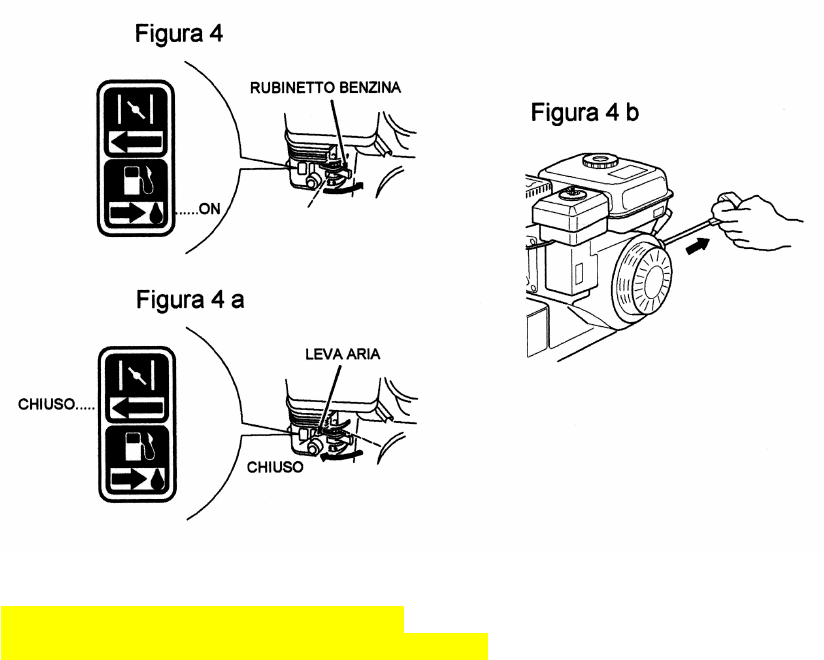
Place the feed cock in the OPEN position (direction shown by the arrow) (fig. 4)
Bring the choke to the CLOSED position for a cold start (direction shown by the ar-
row, Fig. 4a)
Set the accelerator lever at the minimum position.
Grip the engine pull lead handle (fig. 4b) and pull gently until you feel the "bite",
then pull on the lead sharply to overcome the pressure, prevent kickback and
switch on the engine. Repeat the procedure, if necessary, with the accelerator
lever in INTERMEDIATE position. Once the engine is running, set the accelerator
in the MINIMUM position and gently return the choke to the OPEN position (Fig.
4a)
Cleaning of the machine is recommended after use (see the section “Cleaning the
machine”).
Figure 4 Figure 4b Figure 4a
CLOSED CLOSED CHOKE

370310 F112003A
18
DRIVING THE MACHINE
WARNING. When using the machine for the first time it is advisable to get the
feel of it by executing manoeuvres on flat ground free of foreign objects.
After switching on the engine following the instructions given in the previous para-
graph:
1. Move the gear lever (fig. 2, ref. C) to the FORWARD position
Warning. If the gear engages with difficulty, partially engage the clutch for an in-
stant before trying to engage the gear again.
2. Engage the blade control level using the relative lever ( Fig. 1, ref. A)
Warning.
Choose a cutting height suitable for the type of terrain the machine is to be used
on.
3. To move the machine, accelerate and then engage the forward clutch using
The relative lever (Fig. 1, ref. C).
4.To select a different gear the forward clutch and the blade
clutch must first be disengaged by releasing their levers (Fig. 1, ref. C and
Fig. 1, ref. A). Then select the desired FORWARD or REVERSE position
(FWD – REV , in fig. 2, ref. C) using the gear lever (Fig. 2, ref. C),
then re-engage the forward clutch control lever (Fig. 1, ref. C) to set the ma-
chine in motion again.
5. To stop the blade release the relative lever ( Fig. 1 ref. A)
6.To stop forward movement of the machine release the relative lever ( Fig.
1, ref. C)
Then switch off the engine by moving the switch to the position (O) as
shown in figure 1, ref. I).
13. CUTTING TIPS
1) Before commencing cutting operations, read the safety instructions given in the
previous sections.
2) At first the setting of a relatively high cutting height is recommended (using the
relative lever in figure 2, ref. A), lowering it gradually according to working con-
ditions.
3) Engage the blade clutch (Fig. 1, ref. A) only after having carried out the ma-
chine switch-on and gear engagement operations.
4) Before engaging the blade clutch (Fig. 1, ref. A), gradually move the accelera-
tor (Fig. 1, ref. B) until the required speed is reached
WARNING. Take great care because the blade moves at very high speed.
5) Keeping blade movement engaged in reverse is prohibited.

370310 F112003A
19
14. CHECKS
- Adjust the belt and cable control tension after the first few working hours to
compensate initial loosening.
- Briefly operate all the machine's components to detect any abnormal noises
or overheating.
- During the initial running in period avoid heavy-duty usage to encourage
proper settling of the mechanical parts.
- Never neglect maintenance operations after work and carry out all pre-
scribed checks regularly.
A) TIRE PRESSURE
Regularly check the tire pressure. If both sets of tires are not inflated to average
pressure the machine will tend to travel sideways during operation.
B) CABLE CONTROL ADJUSTMENT
To adjust the cables place the machine on flat ground, switch off the engine and
disconnect the wire from the spark plug.
B1)BLADE CONTROL CABLE
Make sure that there is no play between the upper end of the cable and the ad-
justment screw. If there is, or if the cable has stretched, restore to ideal position us-
ing the relative adjustment screw(Fig. 5, ref. A)
If adjustment using the relative screw proves ineffective, the belts, and hence the
engine mounting, must be adjusted. To perform this operation refer to section 14C
“ BELT REPLACEMENT AND ADJUSTMENT” of this manual.
B2) FORWARD CONTROL CABLE
Make sure that there is no play between the upper end of the cable and the ad-
justment screw. If there is, or if the cable has stretched, restore to ideal position us-
ing the relative adjustment screw ( Fig. 5, ref. A).
If adjustment using the relative screw proves ineffective, the belts, and hence the
engine mounting, must be adjusted. To perform this operation refer to section 14 C
“ BELT REPLACEMENT AND ADJUSTMENT” of this manual
Fig.5
370310 F112003A
20
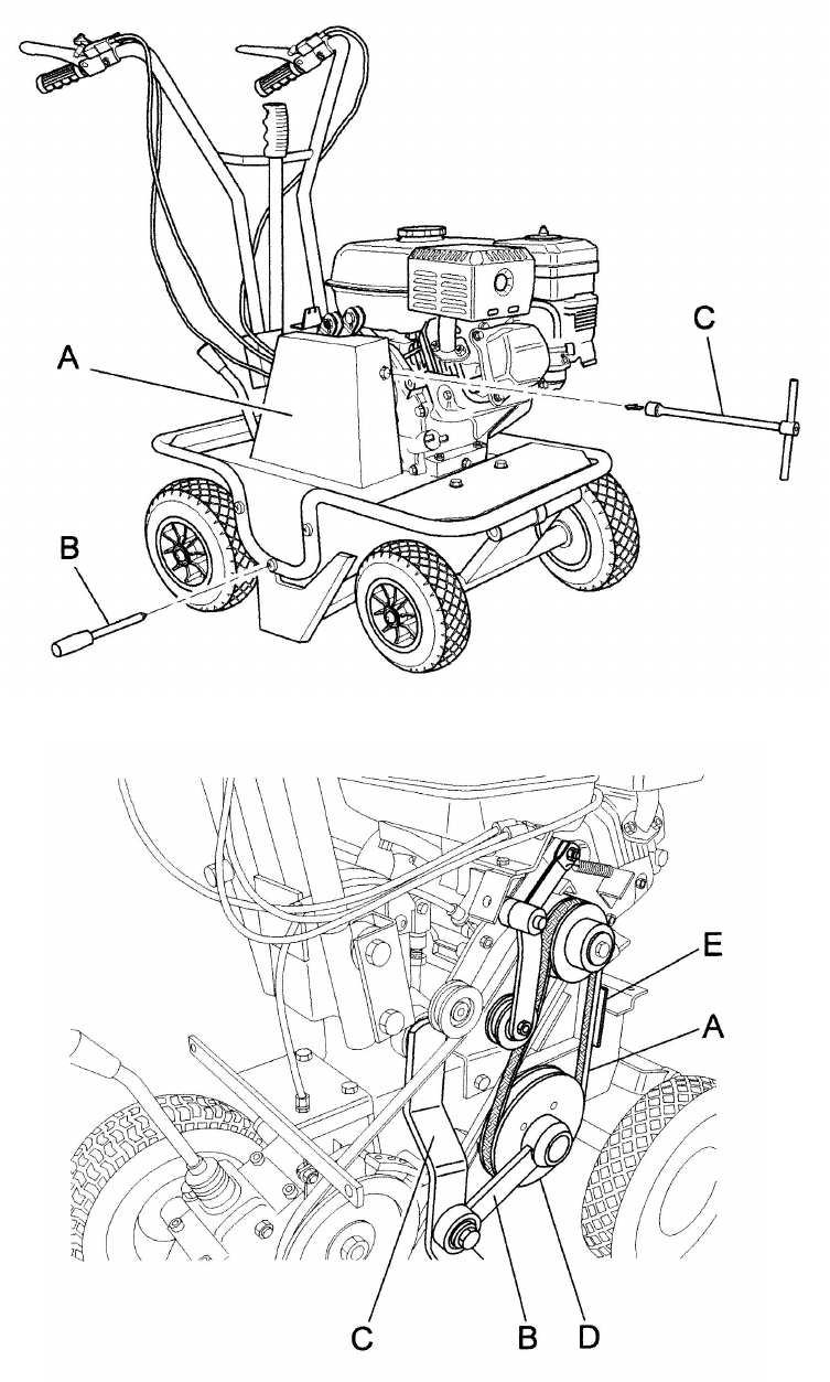
C)BELT REPLACEMENT AND ADJUSTMENT
Switch off the engine and disconnect the spark plug wire before carrying out
any maintenance or repair work on the machine.
If a belt is worn or breaks it should be replaced as follows:
- remove the metal guard ( fig. 6 ref. A), by unscrewing and taking out the screws
shown in figure 6 ref. B and C.
C1)BLADE BELT
Disconnect the connecting rod (Fig. 7 Ref. B) by removing the nut and
loosening the screw that secure it to the arm (Fig. 7 Ref. C)
- Once the connecting rod has been disconnected the belt can be slipped off
(Fig. 7 Ref. A) by manually turning the relative lower pulley anticlockwise (Fig. 7
Ref. D).
- To fit the new belt follow the procedure in the reverse order.
- Afterwards check that the belt is correctly positioned by using the relative blade
control lever. When this lever is lowered and the belt is at maximum tension,
the distance between the belt and the relative belt guides (Fig. 7 Ref. E) should
be approximately 2 mm.
- Then make sure that the belt works properly by tugging lightly on the self-
winding starter cable with the engine switched off and the spark plug wire
disconnected. If everything is working properly the pulley will turn on the engine
but will not engage the belt.
If the belt engages push the engine back slightly towards the rear of the
machine (in the direction of the handlebars) until the belt is in the correct
position.
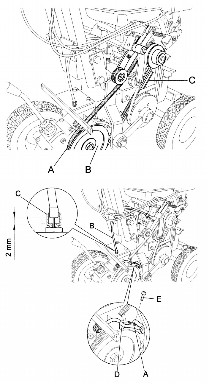
C2)FORWARD CONTROL BELT
Remove the blade control belt following the instructions given in the preceding
paragraph.
- Remove the blade (Fig.1 Ref. G) following the instructions provided in the
section entitled “Blade removal and replacement”.
- Then remove the forward control belt from the lower pulley by turning the belt
anticlockwise (Fig. 8 Ref. A e B)
- To fit the new belt follow the procedure in the reverse order.
- Afterwards check that the belt is positioned and working correctly using the
relative forward control lever. When this lever is lowered and the belt is at
maximum tension, the distance between the belt and the relative belt guides
(Fig. 8 Ref. C) should be approximately 2 mm.
- Then make sure that the belt works properly by tugging lightly on the self-
winding starter cable with the engine switched off and the spark plug wire
disconnected. If everything is working properly the pulley will turn on the engine
but will not engage the belt.
If the belt engages push the engine back slightly towards the rear of the
machine (in the direction of the handlebars) until the belt is in the correct
position.
370310 F112003A
21
Fig. 6
Fig. 7
370310 F112003A
22
Fig. 8
Fig. 9

370310 F112003A
23
D) SERVICE BRAKE CONTROL LEVER
The service brake (Fig. 9 Ref. A) is connected to the forward control lever (Fig. 1
Ref. C).
With the forward control lever released and the brake engaged ensure that there is
play of approximately 2 or 3 mm between the adjustment screw and the brake
cable (Fig. 9 Ref B and C)
WARNING. If there is no such play restore it immediately since the brake will
not stop the machine once the forward control lever is released.
Make sure that the front part of the brake in direct contact with the pulley
(Fig. 9 Ref. D) is not worn. If so, replace it.
E) CHECKING AND REPLACING THE BLADE
Always check the state of the blade before commencing work. Do not forget to
switch the engine off!
- During work operations if the blade (Fig. 10, ref. A ) Strikes stones or
stumps stop straightaway and make sure that it has not become bent or
broken. A damaged blade must be replaced.
- If the blade is very worn, cracked or bent, it may snap and project objects
outwards, risking serious accident.
- Use heavy-duty work gloves to check or replace the blade to avoid risk of in-
jury to hands.
- The blade fixing screws and relative nuts are also subject to wear. Always
replace them at the same time as the blade, using bolts and screws of the
same strength and type.
- The blade wears more quickly on dry, sandy ground. In these conditions it
should be replaced more frequently.
To remove the blade proceed as follows:
1. Switch off the engine and disconnect the spark plug wire
2. Adjust the cutting height to maximum
3. Check the state of the blade.
Check that the blade is not cracked, bent, excessively worn or broken

370310 F112003A
24
FIG. 10
15. MAINTENANCE AND STORAGE
! All operations on the machine must be carried out exclusively by authorized
personnel.
! Always switch off the engine when checking, adjusting or servicing the ma-
chine.
! Allow the machine to cool down before inspection.
! The cover ( Fig. 1 ref. F) must always be correctly installed and intact. If it be-
comes damaged, have it repaired before the machine is used again.
! Make sure that all the guards of rotating and moving parts are in place.
! For greater safety, when replacing the blade replace all the fixing screws and
nuts at the same time, as described in section 14, point D.
! Inspect the fuel lines. These should be replaced if damaged or after a maxi-
mum of three years, along with the fixing bands. Old lines may leak fuel.
! Check and regularly adjust the forward clutch control, blade clutch control, and
accelerator.
! Cover the machine with a sheet after the engine and silencer have cooled
down.
! It is strictly forbidden to place/leave unattended on the sod cutter any potentially
dangerous objects which may put the safety of persons or the machine at risk.
! Keep the machine in a good, clean state; do not leave it outside exposed to in-
clement weather conditions.
! After use store the machine in a place where children have no access. Always
allow the machine to cool down before putting it away.
370310 F112003A
25
! After use store the machine in a place where fuel vapours cannot reach a na-
ked flame or sparks.
! In the instance of a long period of non-use, drain the fuel tank completely.
Use of the machine does not require specific lighting.
However, the recommended minimum amount of light (e.g. 200 lux) to be able to
read the notices on the machine and to operate it without running risks caused by
poor light.
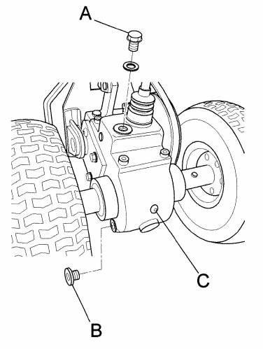
CHECKING AND REPLACING THE TRANSMISSION OIL.
Check the transmission oil level using the relative oil level screw ( fig. 11 ref. C). If
oil leaks out upon removal of this screw then there is enough of it in the transmis-
sion. If not, remove the filling cap shown in fig. 11 ref. A, then top up with SAE 90.
The oil should be replaced after the first 20 hours of use and after this every 100
working hours.
Remove the drainage cap shown in fig. 11 ( ref. B) and allow all the oil to run out.
After refitting the drainage cap, fill the transmission from the filling cap with SAE 90
transmission oil.
Refit the lid securely to prevent any leakage of oil.
Fig. 11
370310 F112003A
26
16. CLEANING THE MACHINE
Proceed in the following order:
- Switch off the engine and disconnect the spark plug wire;
- Clean the engine and the outside of the machine with a cloth soaked in a little
oil.
- Clean all parts of the machine, particularly the starting unit, air filter, exhaust
and carburetor. It is advisable to follow the instructions given in the engine
manual.
- Clean the inside of the belt guard (fig. 1, ref. F) with a blast of compressed air.
- To clean the blade (fig. 1 ref. G), wash with a jet of water straight after use
while still damp.
When washing carefully cover and protect the electrical parts of the engine, the
carburetor, the air filter and the exhaust from the water to prevent engine prob-
lems.
- To clean the blade area a tool should be used (stick of wood).
17. SEASONAL LONG-TERM STORAGE PERIODS
To store the sod cutter for prolonged periods of non-use, proceed as follows:
- Park the machine on flat, firm, clean ground.
- Oil deposits on the ground where the machine is positioned may cause irrepa-
rable damage to the tires.
- Disconnect the spark plug wire;
- Clean the machine carefully as described in section 16 (Cleaning the machine)
- Make sure that all screws and nuts are fully tightened.
- Retouch with paint any parts which have become exposed during use.
- Store the machine in a clean, dry place.
- Empty the fuel tank, following the instructions given in the engine manual;
- Regularly check the tire pressure, and adjust if necessary.
- Lubricate all moving parts and have any necessary repairs to the machine car-
ried out.

370310 F112003A
27
18. DECOMMISSIONING AND SCRAPPING
After the working life of the sod cutter the user must have it dismantled and its
components removed as per EEC directives or in accordance with current legisla-
tion in force in his country, taking particular care over the dismantling of the fol-
lowing materials of environmental impact:
- plastic parts
- rubber parts
- coated electric wiring
- petrol engine
- metal parts
- toxic substances
19. TECHNICAL ASSISTANCE
Routine maintenance must be carried out as per the instructions given in this Man-
ual. For any instances not covered herein and for technical assistance in general
contact your dealer referring to the data given on the identification plate affixed to
the machine.
The right reference will ensure swift, precise answers.
For swift delivery of spare parts always quote the following information on the or-
der:
- Machine model and serial number
- Part description and quantity required
For assistance concerning the engine it is advisable to contact the service centre
authorized by the engine manufacturer (see engine manual supplied)
20. WARRANTY
Should a Billy Goat Machine fail due to a defect in material and / or workmanship,
the owner should make a warranty claim as follows:
-The Machine must be taken to the dealer from whom it was purchased or to
an authorized Servicing Billy Goat Dealer.
-The owner must present the remaining half of the Warranty Registration
Card, or, if this is not available, the invoice or receipt.
-The Warranty Claim will be completed by the authorized Billy Goat Dealer
and submitted to their respective Billy Goat Distributor for their territory.
Attention: Service Manager. Any parts replaced under warranty must be
tagged and retained for 90 days.
-The distributor service manager will sign off on the claim and submit it to
Billy Goat for consideration.
-The Technical Service Department at Billy Goat will study the claim and
may request parts to be returned for examination. Billy Goat will notify their
conclusions to the distributor service manager from whom the claim was
received.
-The decision by the Quality / Service department at Billy Goat to approve or
reject a Warranty claim is final and binding.
Note: To process a Warranty Claim, it is necessary to quote the Model & Serial
Number which are printed on the Billy Goat Serial Plate (See owner’s manual).

370310 F112003A
28
21. TROUBLESHOOTING
The following table illustrates some problems which may arise during operation.
FAULT CAUSE ACTION
Belt slips 1. Belt tension inadequate
2. Too great a working depth
3. Belt worn
1. Adjust the belt tension
2. Reduce the working depth
3. Replace belt
Machine vibrates excessively 1. Belt damaged
2. Blade bent or broken
1. Replace belt
2. Replace blade
Engine overloads during work
operations 1. Engine speed too low.
2. Blade worn
3. Forward speed too high
4. Too great a working depth
1. Accelerate to maximum
2. Replace blade
3. Decrease the forward
speed
4. Reduce the working depth

370310 F112003A
29
ENGINE
FAULT CAUSE MEASURES TO BE TAKEN
Engine sluggish at switch on 1. Accelerator not in start-up
position
2. Choke not closed
3. Petrol does not arrive
4. Air bubbles or water inside
the petrol lines
5. Thick oil prevents rotation
6. Winding or start mecha-
nism faulty
7. Spark plug in poor condi-
tion
1. Move the accelerator to the
intermediate position
2. Close the choke when cold.
3. Check the fuel tank and
remove any water or sedi-
ment.
4. Make sure that the feed
cock is open.
5. Check the lines and bands.
Repair or replace if dam-
aged
6. Use oil with a viscosity
suited to the temperature
7. Replace winding or start
mechanism
8. Clean or replace spark
plug. Adjust the distance
between the electrodes.
Poor power 1. No fuel
2. Air filter blocked
3. Elastic bands worn
1. Refill tank with petrol
2. Clean air filter
3. Replace elastic bands
Engine stalls 1. No fuel
2. Feed cock shut off
1.refill tank with petrol
2.open feed cock
Exhaust fumes dark 1. Low grade fuel
2. Too much engine oil 1. Replace with high grade
fuel
2. Restore engine oil to cor-
rect level
Engine emits black smoke and
power is poor 1. Air filter blocked
2. Choke not fully opened 1. Clean air filter
2. Open the choke completely
Exhaust fumes bluish 1. Too much engine oil
2. Elastic bands worn 1. Restore engine oil to cor-
rect level
2. Replace elastic bands
Silencer becomes red through
overheating
1. Air filter blocked
2. Inside of self-winding
starter blocked with grass
cuttings
1. Clean air filter
2. Clean self-winding starter
housing
For any problems not easily resolved or in case of doubt you are advised to contact your dealer.

370310 F112003A
30
NOTES
_________________________________________________________________________
_________________________________________________________________________
_________________________________________________________________________
_________________________________________________________________________
_________________________________________________________________________
_________________________________________________________________________
_________________________________________________________________________
_________________________________________________________________________
_________________________________________________________________________
_________________________________________________________________________
_________________________________________________________________________
_________________________________________________________________________
_________________________________________________________________________
_________________________________________________________________________
_________________________________________________________________________
_________________________________________________________________________
_________________________________________________________________________
_________________________________________________________________________
_________________________________________________________________________
_________________________________________________________________________
_________________________________________________________________________
_________________________________________________________________________
_________________________________________________________________________
_________________________________________________________________________
_________________________________________________________________________
_________________________________________________________________________
_________________________________________________________________________
370310 F112003A
31

3
2
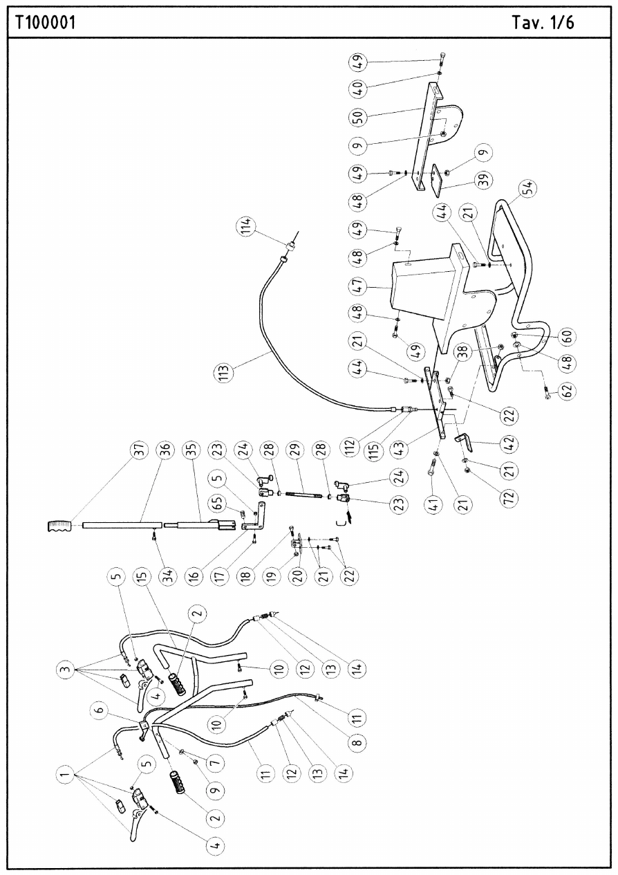
PARTS LIST 1/6
1 370252 Lever Control (righthand ) 1
2 370257 Knob 2
3 370253 Lever Tightener (lefthand) 1
4 370178 Screw M6x55 UNI 5931 2
5 370107 Nut Lock M6 H6 3
6 370255 Lever Hand Accelerator 1
7 370112 Washer Flat M6 1
8 370254 Cable Accelerator 1
9 370148 Nut Lock M6 H8 10
10 370281 Screwcap M10x 20 2
11 370256 Clamp Accelerator 1
12 370186 Spring guide 2
13 370143 Spring 10x25 C X F 2
14 370187 Cable guide 2
15 370274 Handle 1
16 370243 Lever 1
17 370282 Screwcap M6x45 P.F. 1
18 370283 Screwcap M10x50 P.F. 1
19 370149 Nut Lock M10 1
20 370248 Support Lever Height adjustment 1
21 370110 Washer Flat M8 9
22 370126 Screwcap M8x16 3
23 370259 Fork 03216055 2
24 370260 Clip Fork 2
28 370146 Nut M10 2
29 370235 Rod Tie Height-adjustment 1
34 370292 Screwcap M8x16 1
35 370229 Lever Height adjustment 1
36 370275 Extension Height Adjustment Lever 1
37 370189 Knob 0 22 1
38 370125 Nut Lock M8 4
39 370280 Plate Stopping Reverse Gear 1
40 370108 Washer Flat M6x18 6
41 370118 Screwcap M8x25 2
42 370191 Bracket Rear 1
43 370250 Support Rear guard 1
44 370130 Screwcap M8x20 4
47 370268 Guard Belt 1
48 370112 Washer Flat M6 10
49 370128 Screwcap M6 x 14 10
50 370269 Guard Side (lefthand) 1
54 370267 Guard Support Frame 1
60 370129 Nut Lock MS H6.5 6
62 370152 Screw Crosshead MSx30 6
65 370144 Spring 13x25 1

33
PARTS LIST 1/6 CONTINUED
72 370102 Nut 8 H 6.5 1
112 370294 Adjuster M6 X 40 1
113 370295 Cable Control Brake 1
114 370296 Bushing Sheath 1
115 370297 Nut M6 H4 1
3
4

35
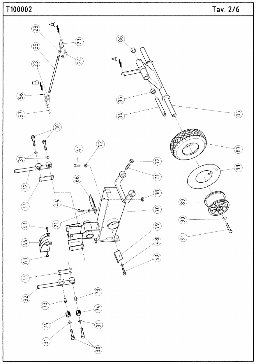
PARTS LIST 2/6
21 370110 Washer Flat M8 2
23 370259 Fork 03216055 2
24 370260 Clip Fork 1
28 370146 Nut M10 1
30 370147 Screwcap M10x50 P.F. 4
31 370145 Washer wave M10 4
32 370228 Support Handle 2
33 370247 Nut Special for handle support 2
38 370125 Nut Lock M8 2
41 370118 Screwcap M8x25 1
44 370130 Screwcap M8x20 2
48 370112 Washer Flat M6 1
55 370236 Connection tie-rod 1
56 370151 Pin Roll M30x2.5 1
57 370258 Pivot Ø 10 1
59 370134 Screwcap M6x10 1
63 370111 Screw Button Head M8x12 4
64 370249 Quadrant Tooth Height 1
66 370251 Support Front guard 1
70 370215 Body Sod Cutter 1
71 370153 Dowel M8x16 2
72 370102 Nut 8 H 6.5 3
73 370284
Dampener Vibration Internal Tube
12x10x28 4
74 370285
Dampener Vibration Handle Support
30x12x28 4
79 370239 Block Sliding Belt No. 1 1
84 370271 Pivot Axle Front 1
85 370218 Axle Front Complete 1
86 370276 Bushing Self-Lubricating 16x20x22 2
87 370206 Tire Front Wheel T090700 2
88 370204 Tube Inner Front Wheel 2
89 370205 Rim Front wheel 2
90 370119 Washer Flat M8x32 2
91 370126 Screwcap M8x16 2
36

37
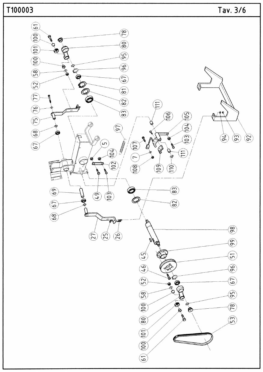
PARTS LIST 3/6
5 370107 Nut Lock M6 H6 1
7 370112 Washer Flat M6 1
25 370136 Nut M8 H5 4
26 370272 Screw Stud M8x20 UNI 5911 4
27 370224 Arm Control Blade (Righthand) 1
45 370157 Key 8x7x25 1
46 370177 Screw Allen M6 x 25 4
49 370128 Screwcap M6 x 14 1
51 370211 Pulley for shaft with eccentrics 1
52 370150 Nut M12 2
53 370197 Belt Short XDV48/290 1
58 370124 Washer Flat M12x24 2
61 370287 Screw Special 2
67 370138 Bearing 17x40x12 6203-2RS 4
68 370135 Shim adjustment 17x24x0.5 2
69 370232 Bushing 1
75 370244 Arm control Blade (lefthand) 1
76 370120 Washer Split M6 1
77 370154 Screwcap M6x85 P.F. 1
78 370286 Cover Plastic Connecting Rod 2
80 370217 Rod Connecting 2
81 370155 Ring Snap Internal E35 1
82 370156 Shim adjustment 35x45x0.5 2
83 370137 Bearing 35x62x14 6007-2RS 2
92 370279 Blade Cutting 1
93 370105 Nut M8 H8 4
94 370123 Washer Wave M8 4
95 370122 Ring Snap Internal E17 2
96 370166 Ring Snap Internal 140 2
97 370309 Spring 1
98 370216 Shaft with eccentrics 1
99 370212 Pulley locking hub 1
100 370231 Semi-cone 4
101 370261 Pad Rubber 2
102 370298 Spring Hook 1
103 370299 Screw Button M6 X 16 2
104 370297 Nut M6 H4 2
105 370300 Brake 1
106 370301 Screwcap M4 X 14 3
107 370302 Clamp 7 X 20 1
108 370127 Nut M6 1
109 370303 Pad Brake 1
110 370173 Ring Radial elastic D 10 1
111 370304 Bushing Self Lock 2
38

39
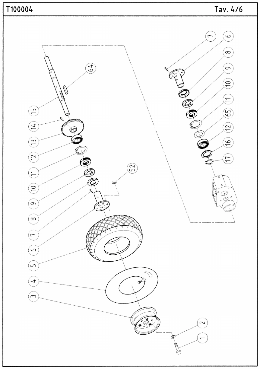
PARTS LIST 4/6
1 370126 Screwcap M8x16 6
2 370110 Washer Flat M8 6
3 370194 Rim Rear wheel 2
4 370277 Tube Inner Rear Wheel 2
5 370278 Tire Rear 2
6 370195 Hub wheel 2
7 370158 Pin Elastic 10x40 2
8 370288 Cover Dust 2
9 370289 Felt protection 2
10 370305 Ring Seal 25 X 52 X 7 2
11 370114 Ring Snap Internal 152 2
12 370131 Bearing 25x52x15 6205 2
13 370199 Gear Reduction-crown 1
14 370180 Dowel M8x14 1
15 370196 Axle Rear 1
16 370142 Shim adjustment 25x35x1 1
17 370290 Seeger E25 1
52 370136 Nut M8 H5 6
64 370170 Key 7x8x35 1
65 370121 Shim Adjustment Ø 42x52x0.5 1
4
0

41
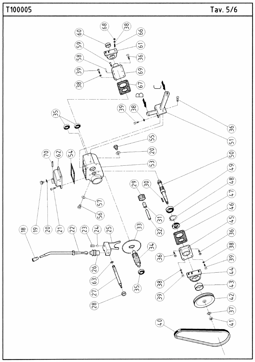
PARTS LIST 5/6
18 370182 Plastic knob Ø 12 1
19 370162 Cap Plastic 1
20 370163 Washer Fiber 1
21 370159 Screw Allen M 8 x 16 4
22 370226 Lever Engage-disengage 1
23 370264 Spring Gear Fork 6x25 1
24 370160 Ball 1
25 370233 Fork Engage-disengage 1
26 370161 Casing 1
27 370227 Fork pivot 1
28 370125 Nut Lock M8 1
29 370201 Gear Reverse-pinion 1
30 370164 Key 5x5x18 1
31 370139 Bushing PCM 1020 12M 1
32 370165 Pin Cylindrical 10x50 1
33 370202 Gear lst and reverse 1
34 370200 Gear Reduction-pinion 1
35 370133 Bearing 15x35x11 6202-2RS 3
36 370104 Screwcap M8x18 4
37 370124 Washer Flat M12x24 1
38 370123 Washer Wave M8 12
39 370130 Screwcap M8x20 6
40 370198 Belt Big 48-430 L443 1
41 370150 Nut M12 1
42 370213 Pulley Cast iron prim. Ø= 150 mm. 1
43 370141 Bushing Self-lubricating 1
44 370209 Support Box (righthand) 1
45 370293 Cover (righthand) 1
46 370240 Gasket Cover (righthand) 1
47 370168 O-ring 17x40x7 1
48 370166 Ring Snap Internal 140 1
49 370179 Bearing 17x40x14 62203 2RS1 1
50 370203 Pinion Primary 1
51 370245 Support Tie Rod 1
53 370207 Gearbox 1
54 370242 Gasket Cover 1
55 370190 Cap Metal 1
56 370183 Button M6x8 1
57 370185 Washer fiber M6x10 1
58 370167 Pin Cylindrical 8x18 2
59 370109 Screw Button Head M8x16 1
60 370140 Bushing Self-lubricating PCM 252820 B 1
61 370210 Support Box (lefthand) 1
62 370208 Cover Box 1

4
2
PARTS LIST 5/6 CONTINUED
63 370171 O-ring 108 (8.73 x 1.78) 1
66 370291 Screw Stud M8 UNI 5911 6
67 370241 Gasket Cover (lefthand) 10
69 370230 Cover Left 1
70 370169 Pin Cylindrical 6x35 1

43

4
4
PARTS LIST 6/6
1 370193 Shim Engine 20x6 2
2 370110 Washer Flat M8 8
3 370234 Support Engine 1
4 370172 Screw TTQST 8x40 4
5 370175 Washer Toroidal M24 4
6 370125 Nut Lock M8 2
7 370126 Screwcap M8x16 2
8 370238 Guide Belt No. 1 1
9 370113 Washer Flat M5 5
10 370106 Screw Allen M5x8 5
11 370237 Guide Belt 1
12 370176 Dowel M8x35 1
13 370130 Screwcap M8x20 2
14 370266 Bracket Guard Support 1
15 370136 Nut M8 H5 4
16 370181 Screw 5/16 x 3/4 mm 19 2
17 370214 Pulley Engine Sect. H 1
18 370119 Washer Flat M8x32 1
19 370123 Washer Wave M8 1
20 370173 Ring Radial elastic D 10 1
21 370117 Ring Snap Internal 132 2
22 370219 Roll Tightening 2
23 370103 Screwcap M8x25 2
24 370116 Bearing 12x32x10 6201 2RS 2
25 370221 Bushing Bearing 2
26 370223 Tensioner Belt 1
27 370101 Shim adjustment 12.2x24x0.8 1
28 370115 Bushing Self-lubricating 2
29 370127 Nut M6 2
30 370220 Clamp 2
31 370188 Clamp spacer 2
32 370246 Tensioner Belt Threaded 1
33 370273 Screw Tensioner 1
34 370306 Screwcap M8 X 40 2
35 370270 Nut Special 1
36 370265 Bracket Guard Fixing 1
37 370184 Screwcap 5/16-24 x 5/8 1
38 370192 Bracket Front 15x3 1
39 370112 Washer Flat M6 3
40 370128 Screwcap M6 x 14 1
41 370262 Spring Cable Return 2
42 600115 Engine Honda 5.5 GX160K1QX2 1
43 370174 Key 4.8x4.8x32 1
44 370222 Spacer 2

45
PARTS LIST 6/6 CONTINUED
46 370263 Spring Accelerator Return 1
47 370107 Nut Lock M6 H6 2
48 370307 Drum Wire Holder 1
49 370297 Nut M6 H4 1
50 370308 Screwcap M6 X 18 1
370310 F112003A
46
