Biolase EPIC EPIC 10 Dental Soft Tissue Laser User Manual 5400321 50912x
Biolase, Inc. EPIC 10 Dental Soft Tissue Laser 5400321 50912x
UserManual.wiki
>
Biolase
>
EPIC User Manual
Users Manual
Navigation menu
Upload a User Manual
Namespaces
Wiki Guide
HTML
PDF
Info
Views
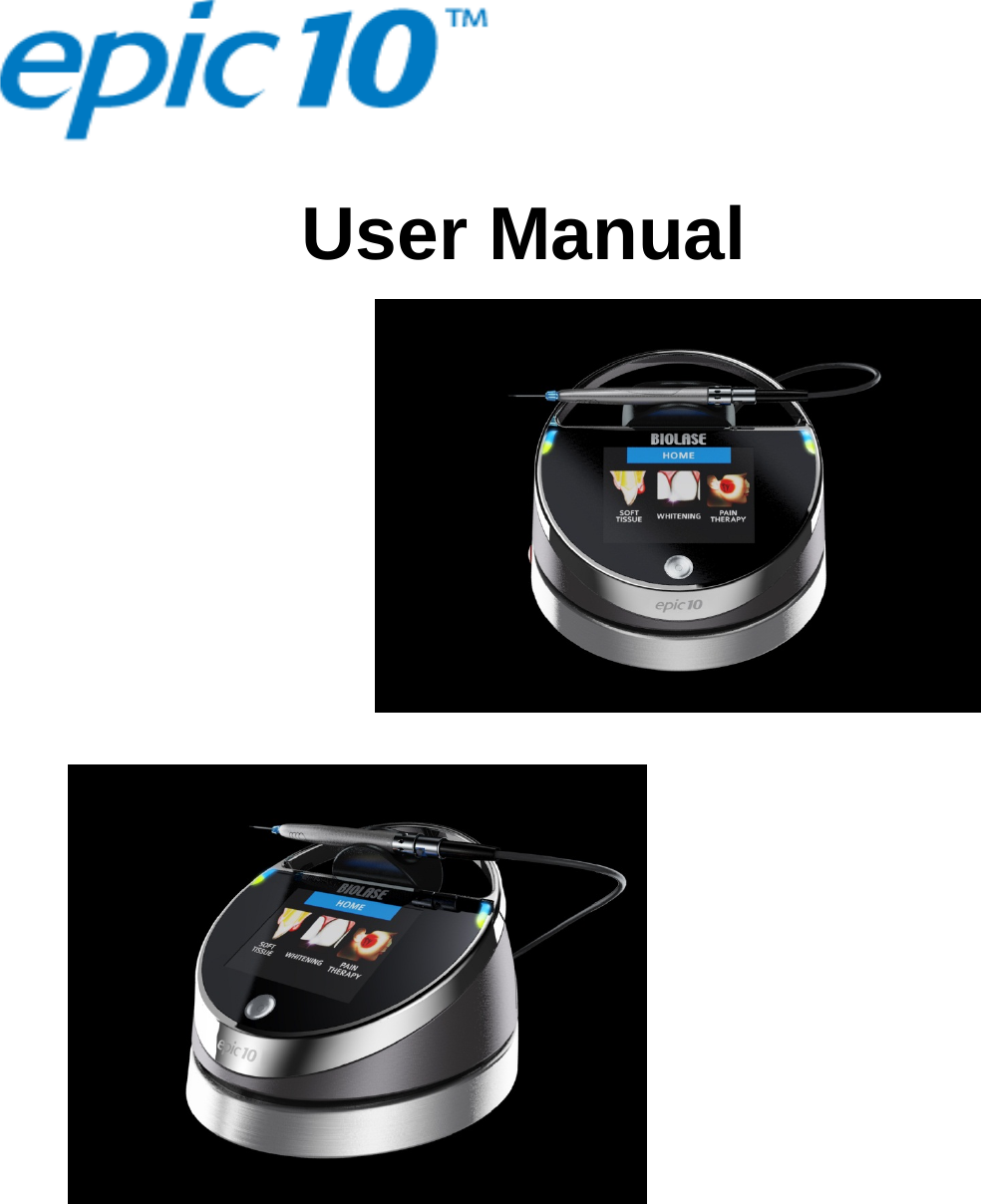
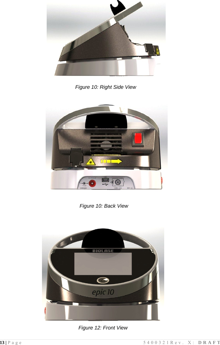
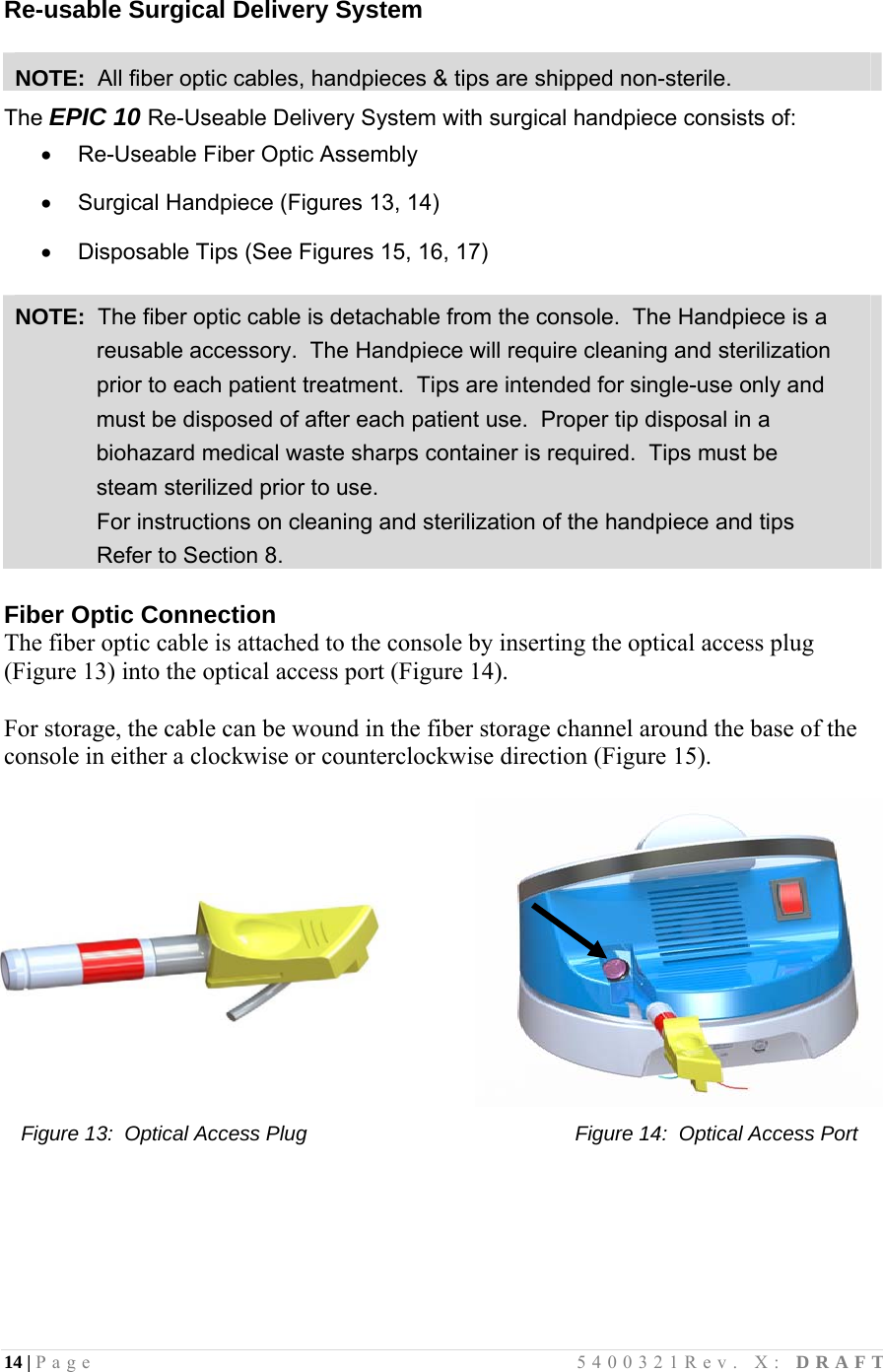
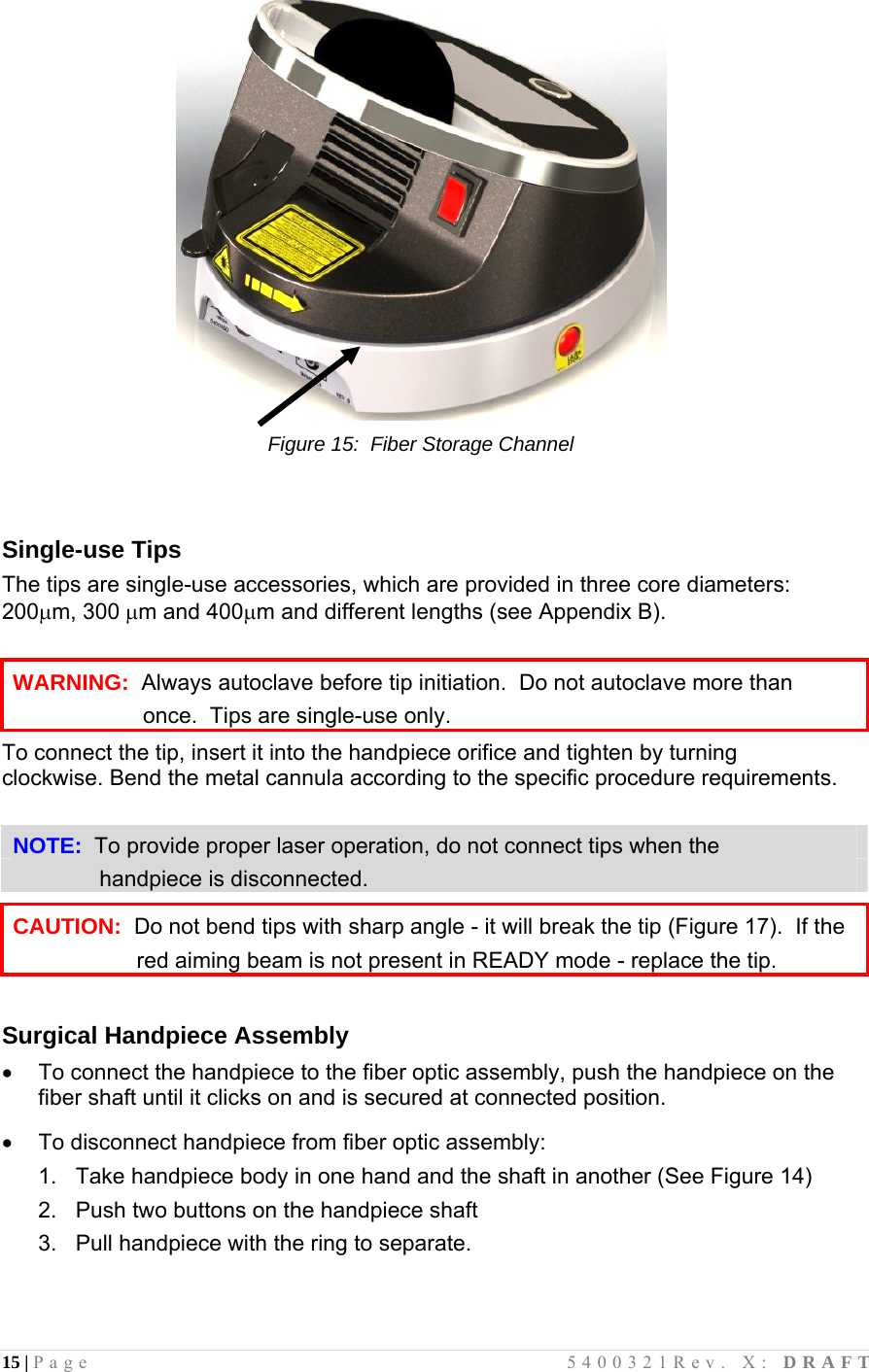
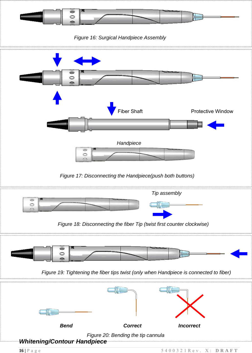
User Manual
Discussion / Help
Navigation
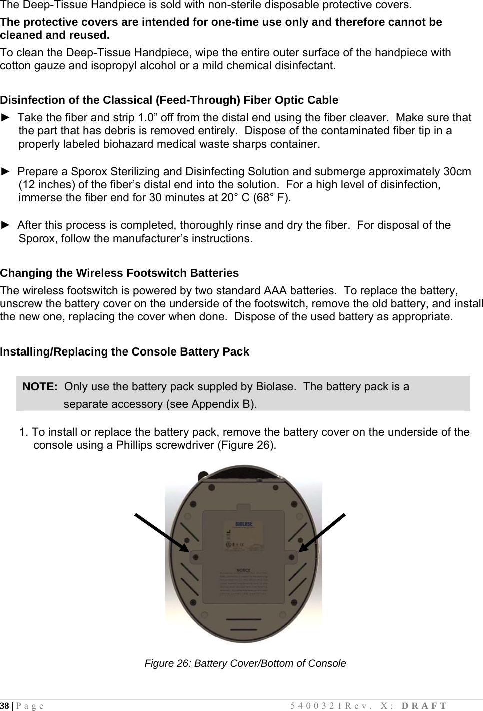
![41 | Page 5400321Rev. X: DRAFT APPENDIX A - LABELS A.1 Identification Location: Bottom of laser console A.2 Footswitch [Engraved] A.3 Laser Aperture Location: Rear of laser console A.4 FCC Compliance Notice Location: Bottom of footswitch](https://usermanual.wiki/Biolase/EPIC/User-Guide-1736044-Page-41.png)