Bioness Neuromodulation A Bioness STRP-PP-V00 Patient Programmer User Manual
Bioness Neuromodulation ltd. A Bioness Inc Company Patient Programmer
user manual

Clinician’s Guide
DRAFT

Worldwide Corporate Office
Bioness Inc
25103 Rye Canyon Loop
Valencia, CA 91355 USA
Telephone: 800.211.9136
Email: info@bioness.com
Website: www.bioness.com
Manufactured by
Bioness Neuromodulation Ltd.
19 Ha’Haroshet Street
PO Box 2500
Industrial Zone
Ra’Anana 43654, Israel
European Authorized Representative
NESS Europe B.V.
Stationsweg 41
3331 LR Zwijndrecht, The Netherlands
Telephone: +31.78.625.6088
Email: international@nl.bioness.com
Website: www.bioness.com
Rx Only
StimRouter™, Bioness, the Bioness Logo® and LiveOn® are trademarks of Bioness Inc. in the United
States or other countries. | www.bioness.com
612-00578-001 Rev. A

Neuromodulation System
Clinician’s
Guide
DRAFT
Rx Only

Copyright
©2012 by Bioness Inc. All Rights Reserved. No part of this publication may be reproduced, transmitted, transcribed,
stored in a retrieval system or translated into any language or any computer language, in any form or by any third
party, without the prior written permission of Bioness Inc.
Guarantees
Bioness Inc reserves the right to modify, without prior notice, information relating to its products to improve their
reliability or operating capacity.
Registered Trademarks
StimRouter™, Bioness, the Bioness Logo® and LiveOn® are trademarks of Bioness Inc. in the United States or other
countries.| www.bioness.com
Patents Pending
This device is protected under one or more of the following U.S. Patents: U.S. Pat. No. 7,502,652. U.S. and foreign
patents pending.
Disclaimer
Bioness Inc shall not be liable for any injury or damage suffered by any person, either directly or indirectly, as a
result of the unauthorized use or repair of Bioness Inc products. Bioness does not accept any responsibility for
any damage caused to its products, either directly or indirectly, as a result of use and/or repair by unauthorized
personnel.
Environmental Policy
Service personnel are advised that when changing any part of the StimRouter system, care should be
taken to dispose of those parts in the correct manner; where applicable, parts should be recycled. When
the life cycle of a StimRouter component has been completed, the product should be discarded according
to the laws and regulations of the local authority. For more information regarding these recommended procedures,
please contact Bioness Inc. Bioness is committed to continuously seeking and implementing the best possible
manufacturing procedures and servicing routines.
European Authorized Representative
NESS Europe B.V.
Stationsweg 41
3331 LR Zwijndrecht, The Netherlands
Telephone: +31.78.625.6088
Email: international@nl.bioness.com
Website: www.bioness.com
Worldwide Corporate Office
Bioness Inc
25103 Rye Canyon Loop
Valencia, CA 91355 USA
Telephone: 800.211.9136
Email: info@bioness.com
Website: www.bioness.com
Manufactured by
Bioness Neuromodulation Ltd.
19 Ha’Haroshet Street
PO Box 2500
Industrial Zone
Ra’Anana 43654, Israel
Conformity Certification
ii
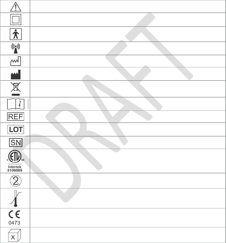
List of Symbols
iii
Caution or Warning
Double Insulated (Equivalent to Class II of IEC 536)
Type BF Applied Part(s)
Non-Ionizing Radiation
Date of Manufacture
Manufacturer
This Product Must Not Be Disposed of with Other Household Waste
Consult Instructions for Use
Re-Order Number
Lot Number
Serial Number
Complies with United States and Canadian Product Safety Standards
Single Patient Use
Storage Temperature
Complies with the European Union Medical Device Directive
Quantity

iv
Clinician’s Guide

Table
of Contents
List of Symbols ........................................................................................................................ iii
Chapter 1: Introduction........................................................................................................1
Chapter 2: Warnings and Cautions .................................................................................. 3
Indications for Use .....................................................................................................................3
Contraindications ...................................................................................................................... 3
Implantation Setting .................................................................................................................. 4
Patient Screening .......................................................................................................................5
Warnings ................................................................................................................................... 5
Magnetic Resonance Imaging ............................................................................................. 5
Pregnancy ............................................................................................................................ 8
Long-Term Effectiveness of Neurostimulation...................................................................... 8
Programming ...................................................................................................................... 8
Device Components ........................................................................................................... 9
Flammable Fuel or Chemicals ............................................................................................. 9
Driving and Operating Machinery........................................................................................... 9
Electromagnetic Compatibility Warnings .................................................................................. 9
Medical Devices/Therapies ................................................................................................. 9
Electrosurgery Devices........................................................................................................ 10
High-Frequency Surgical Equipment ...................................................................................10
Body-Worn Device................................................................................................................10
Security Screening Devices .................................................................................................10
Cell Phones ......................................................................................................................... 11
Precautions ............................................................................................................................. 11
Clinician Training ................................................................................................................. 11
Post-Operative Care ........................................................................................................... 11
Implant Location.................................................................................................................. 11
For Single Patient Use Only ............................................................................................... 11
Postural Changes................................................................................................................ 11
v

Keep out of Reach of Children ............................................................................................ 12
Skin Abnormalities ...............................................................................................................12
Skin Irritation ....................................................................................................................... 12
Known or Suspected Heart Problems ................................................................................. 12
StimRouter Electrode Placement and Stimulation ............................................................... 12
Expiration Date ................................................................................................................... 13
Implant Failure..................................................................................................................... 13
Storage and Handling ......................................................................................................... 13
Adverse Effects ....................................................................................................................... 13
Risks Related to the Implant Procedure ...............................................................................13
RisksRelatedtoStimulation...................................................................................................14
Additional Risks Related to the StimRouter System ............................................................ 14
Chapter 3: Environmental Conditions that Affect Use................................................ 15
Storage and Handling............................................................................................................... 15
Radio Communication Information ...........................................................................................15
Conformity Certification ....................................................................................................... 16
Chapter 4: Clinician Kit...................................................................................................... 17
Description .............................................................................................................................. 17
Chapter 5: Device Description ........................................................................................ 19
Clinician Programmer with Software ........................................................................................ 19
Component Description....................................................................................................... 20
Operating Buttons............................................................................................................... 20
LEDs.................................................................................................................................... 20
SD Slot ............................................................................................................................... 20
Battery ................................................................................................................................ 20
Touchscreen Display ........................................................................................................... 20
24-Pin Connector Port ........................................................................................................ 21
Wireless Bluetooth Communication .................................................................................... 21
Clinician Programmer Memory Card ........................................................................................21
Clinician’s Programmer Charger................................................................................................21
Configuration Cradle ............................................................................................................... 22
vi
Clinician’s Guide

Connector Cable with Charger Adapter ...............................................................................22
Stylus .................................................................................................................................. 22
Tester ...................................................................................................................................... 23
Clinician’s Software Navigation................................................................................................ 23
OperatingModes...................................................................................................................23
Information Icon ...................................................................................................................24
Print Icon..............................................................................................................................25
Data Entry ........................................................................................................................... 25
Menu Bar and Menus .......................................................................................................... 25
Tabs .................................................................................................................................... 26
Buttons ............................................................................................................................... 27
Intensity Level Bar............................................................................................................... 28
Program Bar......................................................................................................................... 29
Search Bars......................................................................................................................... 29
Programming Parameters ................................................................................................... 30
Chapter 6: Set-Up Instructions ........................................................................................33
Programming Components and Software ............................................................................... 33
Connecting the Clinician Programmer and Cradle .............................................................. 33
Charging the Clinician Programmer .................................................................................... 34
Logging into the StimRouter Application ............................................................................. 34
Patient’s External Components ............................................................................................... 35
Connecting the Patient Programmer and Configuration Cradle............................................36
Connecting the StimRouter Electrode and EPT....................................................................37
Adhering the StimRouter Electrode to the Skin.................................................................... 38
Confirming Set-Up .............................................................................................................. 41
Removing the StimRouter Electrode ....................................................................................... 42
Testing the EPT.........................................................................................................................43
Chapter 7: Patient Records and History ....................................................................... 45
Patient Records........................................................................................................................ 45
Adding a Patient with an Unassigned System ..................................................................... 45
Copying a Record for an Existing Patient to an Unassigned System ................................... 47
Adding a Patient with an Assigned System ........................................................................ 48
vii

Opening a Patient Record.................................................................................................... 49
Modifying a Patient Record ................................................................................................. 50
Removing a Patient Record ................................................................................................ 50
Searching for a Patient Record ........................................................................................... 51
Usage History .......................................................................................................................... 52
Viewing a Usage History ..................................................................................................... 52
Printing a Usage History....................................................................................................... 53
Session History........................................................................................................................ 53
Viewing a Session History.................................................................................................... 53
Printing a Session History.................................................................................................... 54
Printing Multiple Sessions......................................................................................................54
Chapter 8: Tools ................................................................................................................. 57
System Information and Component Reset ............................................................................. 57
Resetting the Patient Programmer and EPT ....................................................................... 57
User Administration.................................................................................................................. 58
Adding a User/Administrator................................................................................................ 59
Removing a User/Administrator........................................................................................... 60
Changing a User Password ................................................................................................ 61
Clinician Programmer Database Backup and Restore ............................................................ 62
Manually Backing Up the Database..................................................................................... 62
Enabling Automatic Database Backup ................................................................................ 62
Restoring the Database ...................................................................................................... 63
Chapter 9: Programming Instructions .......................................................................... 65
Stimulation and Time Settings ................................................................................................. 65
Programming Stimulation Settings ...................................................................................... 65
Programming Time Settings ................................................................................................ 67
Programs ................................................................................................................................. 68
Adding a Program................................................................................................................ 68
Viewing a Program ............................................................................................................. 68
Deleting a Program ............................................................................................................. 68
Printing a Program .............................................................................................................. 70
viii
Clinician’s Guide

Chapter 10: Maintenance and Cleaning .................................................................. 70
Battery Replacement ............................................................................................................... 71
Replacing the Clinician Programmer Battery ....................................................................... 71
Cleaning ...................................................................................................................................71
Disinfecting .............................................................................................................................. 71
Electronic Components........................................................................................................ 71
Clinician Kit Carrying Case ................................................................................................. 72
Chapter 11: Troubleshooting .......................................................................................... 73
Patient Forgets Patient Programmer ....................................................................................... 73
Using a Clinic Patient Programmer...................................................................................... 74
Registering the Patient Programmer/EPT ........................................................................... 75
Patient Forgets EPT ................................................................................................................ 76
Patient Loses EPT ................................................................................................................... 77
Patient Brings New EPT and New Patient Programmer ........................................................... 77
Copying Patient Data to New Components......................................................................... 77
Patient Forgets StimRouter Electrode .................................................................................... 78
Troubleshooting Wireless Technology .................................................................................... 78
Chapter 12: Technical Specifications..............................................................................83
Troubleshooting Wireless Technology ................................................................................... 85
Chapter 13: Appendix - EMI Tables ................................................................................ 87
Electromagnetic Emissions.................................................................................................... 87
Chapter 14: Bluetooth Printer Set-Up ............................................................................. 93
Enabling Bluetooth ................................................................................................................. 93
Device Pairing ....................................................................................................................... 97
ix

x
Clinician’s Guide

1
Introduction
The Bioness StimRouter Neuromodulation System consists of the following components
and accessories:
•
•
•
An implantable multi-electrode lead with integrated receiver in loader.
Surgical tools for implantation of the StimRouter lead.
An external programming system with a clinician programmer, a clinician programmer
cradle and charger, a tester and accessories.
A
patient-operated system
with a
rechargeable
EPT, an
external patient programmer,
a
system charger and accessories.
Disposable StimRouter electrodes.
•
•
This guide describes the external
programming components
of the StimRouter Neuromodulation
System, which are provided in the StimRouter Clinician Kit.
Refer to the StimRouter Procedure Manual for a description of the StimRouter Lead Kit, Insertion
Tool Kit, package contents, device specifications and the StimRouter implant procedure.
Refer to the StimRouter User’s Guide for a description of the StimRouter User Kit, including the
StimRouter electrode, EPT, patient
programmer,
external
accessories,
package contents, device
specifications and instructions for use.
Chapter 1 - Introduction
1

2
Clinician’s Guide

2
Warnings and Cautions
Clinicians and patients should know the limitations, warnings and precautions associated with
the StimRouter
Neuromodulation
System. Clinicians should review the warnings and precautions
and instructions for use with the patient. If at any time the clinician or patient is concerned about
the safety or effectiveness of the StimRouter system, then call your local distributor.
The StimRouter programming system and patient-operated system should only be used under
proper medical guidance and as described
in
this StimRouter Clinician’s Guide and
in
the
StimRouter
User’s Guide.
Indications for Use
The Bioness StimRouter Neuromodulation System is intended to provide electrical stimulation
via an implanted lead to a target peripheral nerve, for aid in the management of adults that have
severe intractable chronic pain of peripheral nerve origin, as an adjunct to other modes of therapy
(e.g. medications). The StimRouter is not intended to treat pain in the craniofacial region.
Contraindications
The Bioness StimRouter Neuromodulation System is contraindicated for:
•
Patients who have any active implanted device such as an implanted demand cardiac
pacemaker or defibrillator, or any metallic implant in the immediate area intended
for implant. Maintain a minimum safe separation distance of 15 cm (6 in.) between the
SimRouter system and all other active implanted devices and metallic implants.
A risk/benefit determination should be performed before using the StimRouter system for:
•
Patients exposed to diathermy. Shortwave, microwave and/or therapeutic ultrasound
diathermy should not be used on patients who have a StimRouter Neuromodulation
System. The energy generated by diathermy can be transferred through the StimRouter
system components, causing tissue damage at the lead site and potentially resulting in
severe injury. Diathermy may also damage the StimRouter system components,
resulting in loss of therapy. Injury or damage can occur during diathermy treatment
Chapter 2 - Warnings and Cautions
3

whether neurostimulation is turned on or off. All patients are advised to inform their
health-care professionals that they should not be exposed to diathermy.
Patients exposed to therapeutic ultrasound.
Patients who are unable to operate the StimRouter system.
Patient who are high surgical risks or poor surgical candidates in general.
Patients who have a cancerous lesion present near the target stimulation point or near
to where the StimRouter electrode will adhere.
Patients who are known or suspected to have a nickel allergy. The handles of the
tunneling needle and tunneling needle stylet are nickel plated.
Patients with bleeding disorders or active anticoagulation that cannot be stopped for a
few days close to the time of the surgical procedure.
•
•
•
•
•
•
Implantation Setting
The StimRouter should be implanted in an appropriately outfitted physician office, outpatient
surgical center or hospital surgical center. Fluoroscopy and/or ultrasound should be available if
deemed necessary and be used at the implanting physician’s discretion.
Patient Screening
Candidates for StimRouter therapy should be appropriately screened for selection and fully
informed about the therapy risks and benefits, the surgical procedure, system operation and
self-treatment responsibilities.
Select patients carefully to ensure that:
•
•
•
Their symptoms are of an anatomical and/or physiological origin.
They are appropriate candidates for surgery.
They can properly operate the StimRouter system.
Bioness highly recommends the following screening procedure prior to StimRouter lead
implantation:
•
•
Nerve block using local anesthesia.
Psychological screening using techniques traditionally used for similar types of
procedures and systems.
4
Clinician’s Guide

Bioness recommends the following optional screening procedure prior to StimRouter
lead implantation:
•
Transcutaneous electrical nerve stimulation (TENS) to determine the patient’s
tolerance of stimulation near the anticipated site for the StimRouter electrode.
Please note that some individuals are very sensitive to the sensation to electrical
stimulation applied to the skin.
Warnings
Magnetic Resonance Imaging
MRI Warnings and Precautions
•
Do not scan patients with a specific absorption rate (SAR) level exceeding 2 W/kg. A
scan above 2 W/kg may increase the risk of MR-related heating.
Do not place a local RF transmit coil directly over the Bioness implanted lead.
The entire Bioness implanted lead must always be outside the MR coil and must not
be exposed to any radio frequency field.
•
•
StimRouter External Component Restrictions
All external components of the StimRouter system are contraindicated for the MRI environment.
Therefore, the StimRouter electrode, external pulse transmitter and patient programmer must
be removed before the patient is allowed into the MRI environment.
Chapter 2 - Warnings and Cautions
5
MRI Information
Non-clinical testing has demonstrated that the StimRouter lead is MR Conditional. Patients with
an implanted StimRouter lead can be scanned safely, immediately after implantation, on MRI
cylindrical bore systems that meet the following conditions:
•
•
•
Static magnetic field of 1.5 Tesla (T) or 3 T.
Highest spatial magnetic gradient of 2500 gauss/cm or less.
MR system reported, whole-body-averaged SAR does not exceed 2 W/kg at 1.5 T and
2 W/kg at 3 T.
Do not scan patients with a SAR level exceeding 2 W/kg. A scan above 2 W/kg may
increase the risk of MR-related heating.
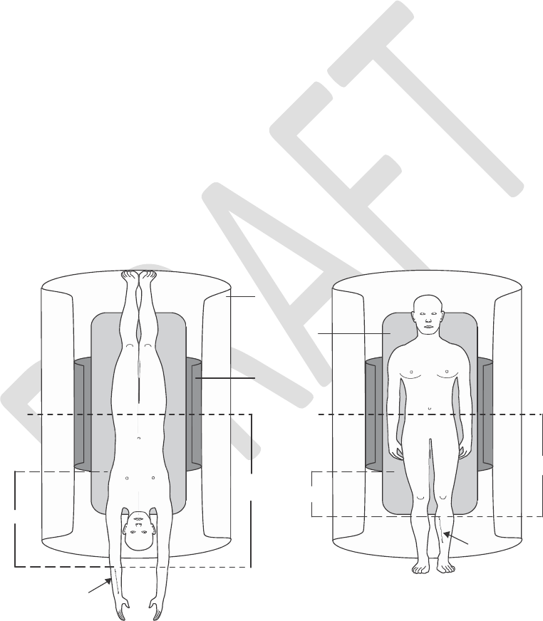
The entire
StimRouter
lead must be at least 50 cm from the
center
of the MR
system’s bore (the iso-center of the bore) and at least 16 cm outside of the MR coil
measured from the edge of the MR coil, to ensure patient safety relative to MRI-related
heating. See Figure 2-1.
•
•
Bore
Table
RF Coil
Isocenter
>50 cm
cm
>16
>16 cm
Lead
Lead
Figure 2-1. The entire StimRouter lead must be at least 50 cm from the center of the MR system’s bore
(the iso-center) and at least 16 cm outside of the MR coil measured from the edge of the MR coil.
Left: lead implanted in the forearm. Right: Lead implanted in the lower leg.
6
Clinician’s Guide
cm
>50

•
Communication is maintained with the patient so that the scan can be promptly
terminated in the event of painful nerve stimulation or other adverse event.
Information regarding the position of the lead is necessary for routine MRI procedures. Review
of the patient’s Medical Device Identification Card, direct communication with the implanting
physician or obtaining an x-ray is recommended to determine the location of the implanted lead.
Patients must be screened for previously implanted (active or abandoned) medical devices,
leads, lead extenders or lead adapters.
MRI-Related Heating: Supplemental Information
1.5 T/64 MHz
Temperature changes of the electrodes of the StimRouter lead were measured at 1.5 T/64 MHz
according to ASTM F2182 (GE Signa, 46- 258170G1, whole body transmit radio frequency
(RF) coil). With the lead in an orientation and a position in the phantom to produce worst-case
heating, the greatest measured temperature rise scaled to a background local SAR of 1 W/kg
was 3.9°C after six minutes of RF power application. This temperature change was with the lead
in an elongated, “straight”
configuration
(i.e., no curves), which produced the highest temperature
change. With the lead in curved or looped configurations, temperature changes were less.
A
computer simulation that incorporated
the
worst-case measured rise and
a whole-body-averaged
SAR of 2 W/kg predicts a worst case in the patient during MRI of less than 2°C provided that
the entire StimRouter lead is at least 50 cm from the center of the bore of the MR system and at
least 16 cm outside of the MR coil measured from the edge of the MR coil.
3 T/128 MHz
Temperature changes of the electrodes of the StimRouter lead were measured at 3 T/128 MHz
according to ASTM F2182 (GE Signa, 3T HDx, Software Version 15/LX/MR, 15.0.M4.0910a).
With the lead in an orientation and a position in the phantom to produce worst-case heating, the
greatest measured
temperature
rise scaled to a local background SAR of 2 W/kg was 2.9°C after
six minutes of RF power
application.
This temperature change was with the lead in an elongated,
“straight” configuration (i.e., no curves), which produced the highest temperature change. With
the lead in curved or looped configurations, temperature changes were less.
A
computer simulation that incorporated
the
worst-case measured rise and
a whole-body-averaged
SAR of 2 W/kg predicts a worst case in the patient during MRI of less than 1°C provided that
the entire StimRouter lead is at least 50 cm from the center of the bore of the MR system and at
least 16 cm outside of the MR coil measured from the edge of the MR coil.
Chapter 2 - Warnings and Cautions
7

Image Artifacts
MR image quality may be compromised if the area of interest is in the exact same area
or relatively close to the position of the StimRouter lead. Therefore, optimization of MR
imaging parameters to compensate for the presence of the StimRouter lead may be
necessary.
Induced Currents
The electric fields induced in the patient with the StimRouter lead by the pulsed gradient fields
were
calculated.
The induced current will be less than the stimulation threshold if the StimRouter
lead is at least 50 cm from the center of the bore and at least 16 cm outside of the MR coil
measured from the edge of the MR coil.
Potential Adverse Events
Use of MRI could result in excessive heating of the lead if the MRI conditions of use are not
followed. Induced voltages in the lead may occur, possibly causing uncomfortable levels
of neurostimulation.
Note: The StimRouter lead is not a life-sustaining device and could be explanted prior to an
MRI procedure.
Pregnancy
The effects of electrical stimulation on pregnancy are unknown. Patients should avoid exposure
to electrical stimulation for the entire duration of pregnancy.
Long-Term Effectiveness of Neurostimulation
The long-term effectiveness of neurostimulation is unknown.
Programming
The StimRouter components should only be programmed by the treating clinician and/or under
proper medical guidance.
8
Clinician’s Guide

Device Components
The use of non-Bioness components with the StimRouter system may result in damage to the
system and increased risk to the patient.
Flammable Fuel or Chemicals
Advise patients to turn the StimRouter system (patient programmer and stimulation) off when
near a refueling point, flammable fuel, fumes or
chemicals.
The operation of the StimRouter could
cause the chemicals or fumes to ignite, causing severe burns, injury or death.
Driving and Operating Machinery
StimRouter stimulation should be off while driving and operating machinery.
Electromagnetic Compatibility Warnings
Medical Devices/Therapies
The following medical therapies or procedures may turn stimulation off, may cause permanent
damage to the external components and may injure the patient, particularly if used in close
proximity to the system components:
•
•
•
•
•
•
Lithotripsy
Electrocautery
External defibrillation
Ultrasonic scanning
High-output ultrasound
Electromagnetic interference
(EMI) from the
following medical procedures
is
unlikely
to
affect the StimRouter system:
Computerized Axial Tomography (CT or CAT) scans
Diagnostic ultrasound (e.g., carotid scan, Doppler studies)
Diagnostic x-rays or fluoroscopy
•
•
•
Note: Advise patients to remove the StimRouter electrode before undergoing medical therapies
or procedures.
Chapter 2 - Warnings and Cautions
9

Electrosurgery Devices
Electrosurgery devices should not be used in close proximity to an implanted StimRouter lead.
Contact between an active electrode of the electrosurgery device and the implanted lead can
cause direct stimulation of the target stimulation point and severe injury to the patient.
High-Frequency Surgical Equipment
Simultaneous
connection of a patient to the StimRouter
components
and
high-frequency
surgical
equipment may result in skin burns where the gel electrodes adhere to the skin and may damage
the
StimRouter EPT. Advise patients
to
remove
the
StimRouter electrode before medical
treatment.
Body-Worn Devices
Although unlikely, body-worn medical devices may interfere with the RF communication used in
the StimRouter system. Stimulation control may be delayed. Examples of a body-worn device
are an insulin pump and a monitoring device. The patient programmer will emit visual alerts if
interference
occurs. To minimize
interference,
maintain a minimum safe separation distance of 15
cm (6 in.)
between
the
SimRouter system
and all
other electronic devices.
See
the
Troubleshooting
section for help. See the Appendix for more information.
The
StimRouter system wireless technology
may
cause
EMI to other
body-
worn
medical
devices.
Refer to the instructions for use for those devices for information on recommended minimum
separation distances.
Security Screening Devices
Certain types of security devices may affect stimulation. Examples include those used at the
entrances and exits of public buildings such as libraries, airports and retail stores. Ask for help
to bypass the device. Show your Medical Device Identification Card. If you must pass through
the device:
•
•
•
Turn off your StimRouter system.
Pass through the device quickly.
Stay as far from the emitter as possible. Walk, for example, in the center of a pass-
through security gate.
10
Clinician’s Guide

Cell Phones
There is potential for interference between electronic devices, including cell phones. Stimulation
control may be delayed. If interference is suspected or anticipated, distance yourself from the
source of interference. To minimize interference, maintain a minimum safe separation distance
of 15 cm (6 in.) between the StimRouter system and all other electronic devices.
Precautions
Clinician Training
Bioness requires
that
clinicians involved
with the use of the
StimRouter system
be
formally
trained
by Bioness in the system’s operation and use.
Post-Operative Care
Clinicians should adequately observe the incision site and monitor for infection, possible device
rejection or other possible adverse effects. If the patient notices excessive redness or discharge
around the incision site, then the implant physician should be contacted immediately to check for
infection and administer proper treatment following standard medical procedures.
Implant Location
Advise patients to never manipulate the StimRouter lead. If the lead is moved from the target
stimulation point, then it may not function correctly or effectively. In some instances a lead can
move from its original location, thus causing a loss of stimulation at the target stimulation point.
If the lead moves, then the lead may need to be replaced.
For Single Patient Use Only
The StimRouter electrode is meant to be worn only by the patient for whom it is prescribed and
in the location for which it is prescribed. The StimRouter electrode should not be adhered to any
other person or any other place on the patient’s body.
Postural Changes
Changes in posture or abrupt movements may decrease or increase the perceived level of
stimulation. Advise patients to turn off stimulation before making extreme posture changes or
abrupt movements such as stretching, lifting of arms overhead or exercising.
Chapter 2 - Warnings and Cautions
11

Keep out of Reach of Children
The StimRouter components should be kept out of the reach of children.
Skin Abnormalities
Do not adhere the StimRouter electrode to sites that are swollen, infected or inflamed, or that
have skin eruptions such as phlebitis, thrombophlebitis and varicose veins. Do not adhere the
StimRouter electrode to skin that is breached.
Skin Irritation
It is normal for the skin under the StimRouter electrode to become red. The redness should
disappear in approximately one hour once the user patch is removed. However, some patients
may experience skin irritation, an allergic reaction, or
hypersensitivity
to the electrical stimulation
or the gel electrodes. Persistent redness, lesions or blisters are signs of irritation. Use of the
StimRouter components should be temporarily halted until the irritation is resolved. In some
cases, irritation can be avoided by removing the StimRouter electrode periodically to allow the
skin to breathe and changing the stimulation parameters. Patients should consult their clinician
if irritation persists.
Known or Suspected Heart Problems
Use caution when treating patients with suspected or diagnosed heart problems.
StimRouter Electrode Placement and Stimulation
•
Electrical stimulation should not be applied trans-thoracically or at the heart such that
current may travel into or through the cardiac tissue, as such introduction of electrical
current may cause heart rhythm disturbances.
Turn off stimulation before adhering, removing or handling the StimRouter electrode.
StimRouter electrode placement and stimulation settings should be determined by the
implanting physician and/or treating clinician.
Do not apply the StimRouter electrode over any obstruction that would reduce
the designated electrode surface area (for example, an adhesive bandage). A smaller
electrode surface area could result in serious injury to the patient.
Do not apply the StimRouter electrode over skin folds, scarred tissue, irritated skin,
uneven skin surfaces or broken skin.
•
•
•
•
12
Clinician’s Guide

•
Always inspect the gel electrodes before use. Do not apply the StimRouter electrode if
the gel electrodes appear dried out, worn, dirty or irregular.
Make sure the gel electrode liners are removed before applying the user patch.
Do not handle the StimRouter electrode with both hands while stimulation is on;
serious injury can result from current passing through the cardiac tissues.
•
•
Expiration Date
Do not use a StimRouter electrode with a “Use by” date that has expired.
Implant Failure
Leads may fail at any time because of random component failure or lead breakage. If component
failure or lead breakage occurs, then the lead may need to be replaced.
Storage and Handling
All StimRouter components and accessories should be handled with care. Components and
accessories should not be dropped. Although reliability testing has been performed to ensure
quality manufacturing and performance, dropping the components on hard surfaces, or other
rough handling, can permanently damage the components.
Refer to the HP product literature included in the Clinician Kit for storage temperatures for the
Hewlett Packard iPAQ 210 Enterprise Handheld.
Tester Storage Temperature Range: -20°C to +60°C.
Adverse Effects
In the unlikely event that any of the following occurs, patients should stop using their StimRouter
components, remove the StimRouter electrode and immediately consult their clinician or their
implant physician.
Risks Related to the Implant Procedure
Suboptimal lead placement may necessitate therapeutic adjustment and/or lead explant. Nerve
injury is possible, although unlikely. Possible surgical complications include infection, cellulitis,
abscess, fever, sepsis, bleeding and temporary pain at the implant site.
Chapter 2 - Warnings and Cautions
13

Risks Related to Stimulation
•
Operation of the StimRouter components may cause increased pain in an area other
than the lead site. This pain may be caused by stimulation of the tissue surrounding
the stimulation electrodes (e.g., skin, fascia and muscle).
Patients may also experience an undesirable motor response during stimulation.
•
If patients experience any pain or discomfort during stimulation, or notice any skin abnormalities,
they should stop stimulation immediately, remove the StimRouter electrode and contact their
clinician.
Additional Risks Related to the StimRouter System
•
•
•
Migration of the lead may cause changes in stimulation effectiveness.
While very unlikely, a tissue reaction to any of the implanted materials may occur.
External electromagnetic interference may cause the StimRouter components to
malfunction and may affect stimulation.
Patients may experience persistent pain at the implant site of the lead.
Although rare, the skin overlying the lead may erode.
Portable and mobile radio frequency communications equipment can affect medical
electrical equipment.
The StimRouter external components could overheat if the components fail, which
could cause burning.
•
•
•
•
If patients experience any pain or discomfort during stimulation, or notice any skin abnormalities,
they should stop stimulation immediately, cease contact with the StimRouter components and
notify their clinician.
14
Clinician’s Guide

3
Environmental Conditions that Affect
Use
Storage and Handling
All
StimRouter components should
be
kept dry and protected from extreme changes
in temperature
and humidity. Do not use or store
components
where they could come in contact with water, such
as by sinks, bathtubs and shower stalls. Do not expose components to weather conditions such
as rain or snow, or to any other source of water.
Do not store StimRouter components in a car or elsewhere where hot or cold temperatures
could exceed the acceptable ranges of the components. Temperature extremes can damage
the StimRouter components.
To avoid
condensation
when
transporting
StimRouter
components
from hot to cold temperatures,
place the components in an air-tight plastic bag first. Let them adjust slowly (for at least two
hours) to the change in temperature before use.
Radio Communication Information
Several components of the StimRouter system communicate via radio communication and have
been tested and found to comply with the limits for a Class B digital device, pursuant to Part 15
(Radio Frequency Devices) of the FCC Rules. These limits are designed to provide reasonable
protection against harmful interference in a residential environment. This equipment generates,
uses and can radiate radio frequency energy and, if not operated and used in accordance with
the instructions, may cause harmful interference to radio communications. However, there is
no guarantee that interference will not occur in a particular environment. If this equipment does
cause harmful interference to radio or television reception, which can be determined by turning
the equipment off and on, then try to correct the interference by one or more of the following
measures:
•
•
•
Reorient or relocate the receiving antenna.
Increase the separation between the equipment and receiver.
Consult the dealer or an experienced radio/television technician for assistance.
Chapter 3 - Environmental Conditions that Affect Use
15

The antenna for each transmitter must not be located near to or operating in conjunction with
any other antenna or transmitter.
Changes or modifications to components not expressly approved by Bioness could void the
user’s authority to operate the equipment.
Conformity Certification
The StimRouter complies with Part 15 of the FCC Rules. Operation is subject to the following
two conditions:
1.
2.
This device may not cause harmful interference, and
This device must accept any interference received, including interference that may
cause undesired operation.
16
Clinician’s Guide
4
StimRouter Clinician
Kit
Description
The StimRouter Clinician Kit contains the clinician programming components of the StimRouter
Neuromodulation System, used to program the StimRouter EPT and Patient Programmer.
Your StimRouter Clinician Kit includes the following:
•
•
•
•
•
•
•
Clinician Programmer with Software
Clinician Programmer Memory Card
Clinician’s Programmer Charger
Configuration Cradle
Tester
Clinician’s Reference Card
HP product literature
Clinician’s
Programmer Charger
EPT Tester
Clinician Programmer
Configuration Cradle
Chapter 4 -
Clinician Kit
17

18
Clinician’s Guide
5
Device Description
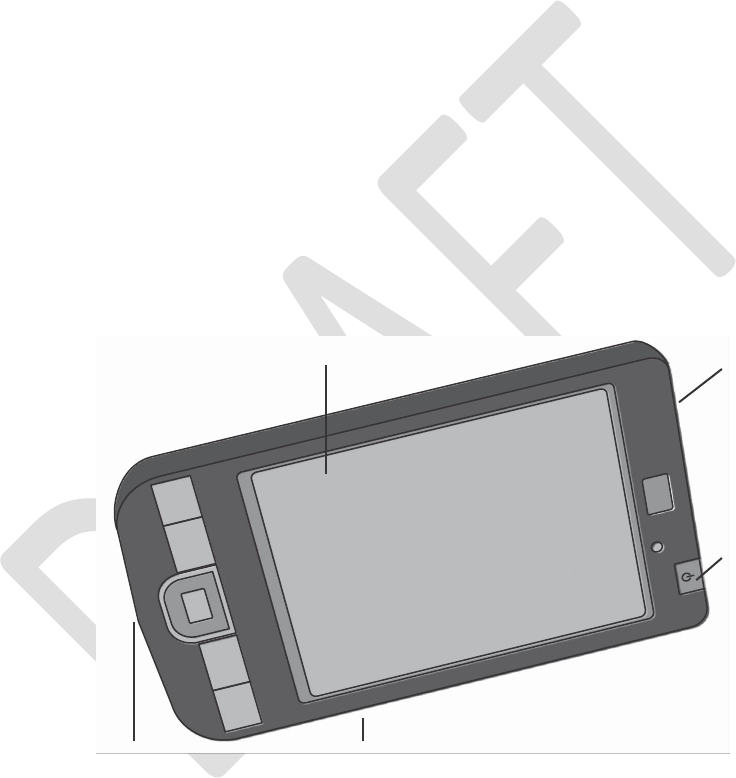
Clinician Programmer with Software
The StimRouter clinician programmer is used to program, test and save stimulation parameters
and programs on the StimRouter EPT and patient programmer. See Figure 5-1. All stimulation
parameters and programs are stored on the clinician programmer as well.
When connected to the StimRouter clinician programmer cradle and patient programmer, the
clinician programmer can wirelessly communicate with the EPT.
Touchscreen Display
SD Slot
with Memory
Card Installed
On/Off Button
24-Pin Connector Port
Reset Button
Figure 5-1. The StimRouter clinician programmer.
The
clinician programmer
is
portable
and
comes
with the
StimRouter software installed,
a memory
(SD) card installed, a rechargeable Lithium- Ion battery installed and a clinician programmer
charger.
Chapter 5 - Device Description
19

WARNING: The clinician programmer should only contain the installed Windows Mobile®
operating system and Bioness Inc proprietary StimRouter software. Do not use the clinician
programmer for any purpose other than that described
in
this manual. Third-party software
packages
are not supported and may interfere with proper operation of the StimRouter components, thus
voiding the warranty.
Component Description
Hewlett Packard iPAQ 200 Enterprise Handheld internally powered personal digital assistant
with StimRouter proprietary software installed.
Note: Refer to the HP web site for a description of the Hewlett Packard iPAQ 200 Enterprise
Handheld, device specifications and instructions for use.
Operating Buttons
On/Off. Used to turn the clinician programmer on and off.
Reset. Used to soft reset the clinician programmer.
LEDs
Power Indicator Light.YELLOW when the clinician programmer is charging; GREEN when the
clinician programmer battery charge is complete.
Bluetooth Enabled Indicator Light. BLUE when Bluetooth is ON.
SD Slot
Contains the clinician programmer memory (SD) card.
Battery
Removable/rechargeable 2200 mAh Lithium-Ion battery.
CAUTION: Risk of explosion if battery is replaced by an incorrect type. Dispose of used
batteries according to local regulation.
Touchscreen Display
Used to navigate the StimRouter application, read statuses and enter data. Use the pointed
end of the stylus to make contact with the display screen. Use only the stylus. Do not use sharp
objects such as pencils or pens on the touchscreen display.
20
Clinician’s Guide

24-Pin Connector Port
For use with the connector cable on the clinician programmer cradle.
Wireless Bluetooth Communication
Used for high-speed, low-power, short-range wireless communication with a Bioness-approved
Bluetooth printer.
Clinician Programmer Memory Card
Used to back up and restore the clinician programmer database. The memory card is supplied
installed in the SD slot of the clinician programmer.
Clinician’s Programmer Charger
Used to recharge the clinician programmer battery.
WARNING: Use only the clinician
programmer
charger included in the StimRouter Clinician
Kit (Manufacturer Model No. PHIHONG, PSC11R/PSM11R).
Chapter 5 - Device Description
21
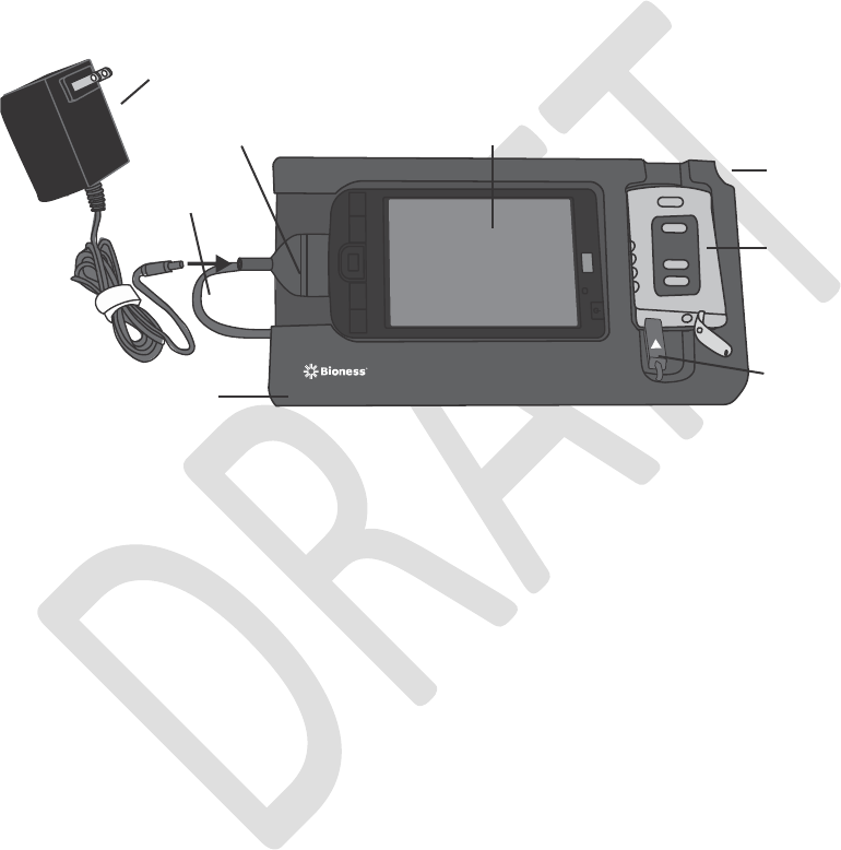
Configuration Cradle
Used to connect the clinician programmer to the patient programmer and to the clinician’s
programmer
charger. The configuration cradle is designed to house the patient programmer and the clinician
programmer in a convenient, portable unit. See Figure 5-2.
Charger
Clinician Programmer
Charger Adapter
Stylus (not shown)
Connector
Cable
Patient Programmer
Connector Cable
Configuration Cradle
Figure 5-2. The configuration cradle with
the clinician programmer and patient programmer connected.
Connector Cable with Charger Adapter
Connects the clinician programmer to the patient programmer and to the clinician’s programmer
charger.
Stylus
A pen-shaped device used to input commands on the clinician programmer touchscreen display.
22
Clinician’s Guide
Tester
Used to confirm that the EPT is working properly. See Figure 5-3.
Figure 5-3. The tester.
The tester is used to diagnose stimulation problems in the EPT. It provides audio feedback
when connected and stimulation is applied.
Clinician’s Software Navigation
The StimRouter clinician’s software is provided installed on the clinician programmer.
Operating Modes
The StimRouter application has two operating modes: online and offline.
Online.
The StimRouter clinician programmer
is
online when connected to an operational
StimRouter
patient programmer and EPT. See Table 5-1.
Offline. The StimRouter clinician programmer is offline when not connected to an operational
StimRouter patient programmer and EPT. See Table 5-1.
Chapter 5 - Device Description
23
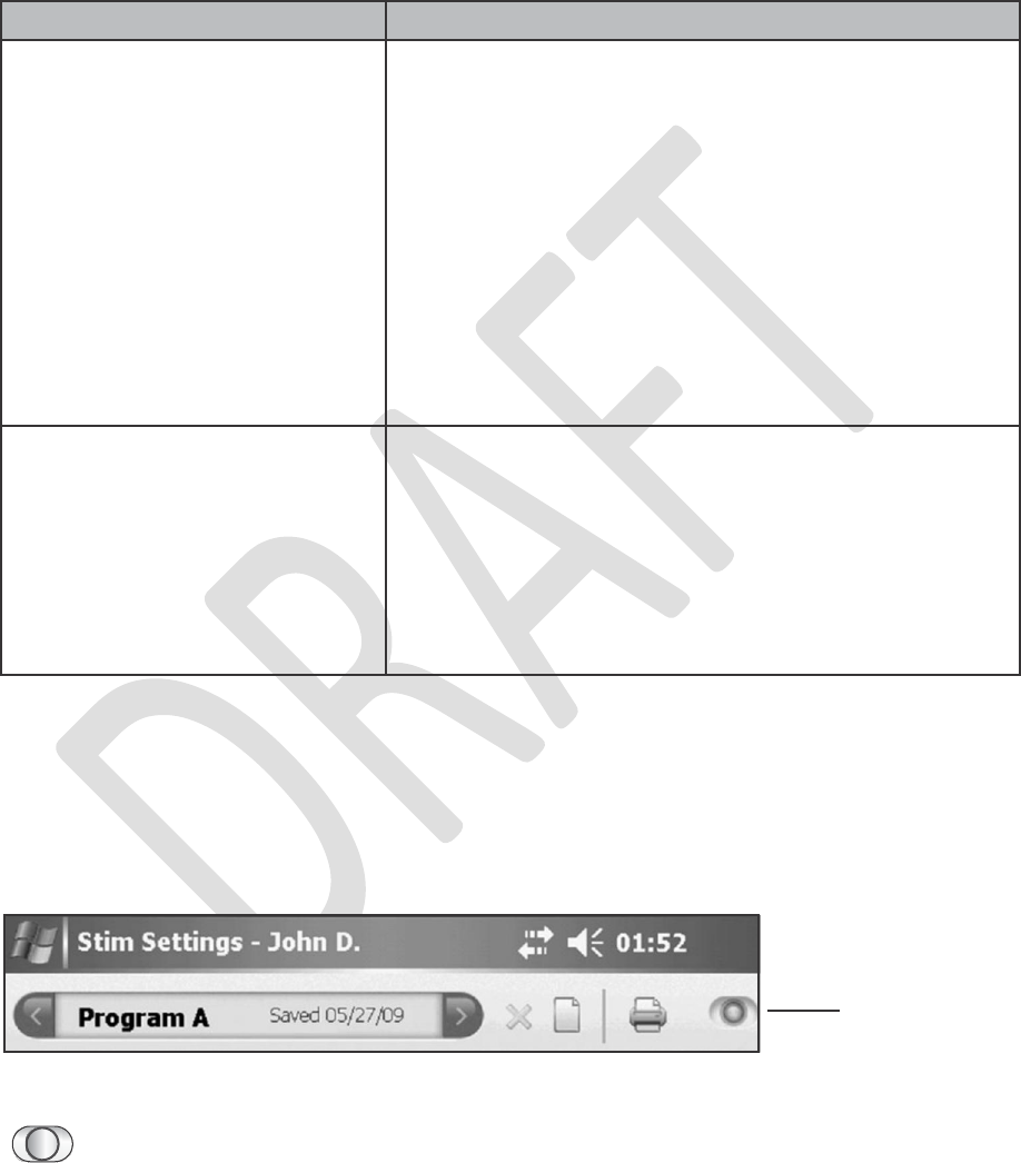
Table 5-1. StimRouter application operating modes and descriptions.
Information Icon
Used to communicate system status, error messages and troubleshooting solutions. When the
icon is RED or YELLOW, press the icon with the stylus for more information. See Figure 5-5.
Information Icon
Figure 5-5. Location of the information icon.
•
GREEN when the StimRouter is online; GRAY when no patient programmer is
detected.
24
Clinician’s Guide
Operating Mode
Function Descriptions
Online
• Add a new patient.
• Modify a patient name.
• Open a patient record.
• View/print a patient’s history.
• Program stimulation settings.
• Program time settings.
• Add or remove a stimulation program.
• View the system information.
• Reset the EPT and patient programmer.
• Back up the database.
• Restore the clinician programmer database.
• Add a new user.
• Remove a user.
• Change a user password.
Offline
• Open any patient record.
• Remove a patient record.
• View/print a patient’s history.
• View a patient’s programs.
• Back up the clinician programmer database.
• Restore the clinician programmer database.
• Add a new user.
• Remove a user.
• Change a user password.
•
FLASHING RED with “i” in the center when a patient programmer is connected
and a correctable error has occurred (for example, RF communication failure).
CONSTANT RED with “i” in the center when a patient programmer is connected
and an error has occurred.
FLASHING YELLOW with “i” in the center when the StimRouter patient
programmer or EPT battery charge level is low.
•
•
Print Icon
Used to print patient reports.
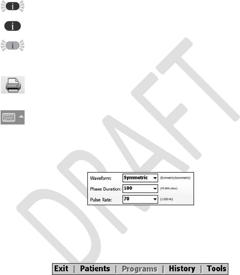
Data Entry
Keyboard. Used to enter characters in a field that requires alphanumeric input. The
keyboard appears collapsed at the bottom right or center of most screens. To enlarge or reduce
the keyboard, touch the keyboard with the stylus. To enter data, select each character using the
stylus.
Drop-Down Lists. Used to select a value. Press the down arrow to display the values. Use the
stylus to select a value. See Figure 5-6.
Figure 5-6. Illustrative drop-down lists for waveform, phase duration and pulse rate.
Menu Bar and Menus
The StimRouter application has five navigation menus, which appear on the menu bar. See
Figure 5-7.
Figure 5-7. Menu bar.
Exit. Used to exit or logoff the StimRouter application.
Patients. Used to open a patient record, add a new patient, modify a patient record or remove
a patient record.
Chapter 5 - Device Description
25

Programs. Used to program, test and save a set of stimulation and time settings. (Enabled when
a patient record is open.)
History. Used to view or print a patient’s usage log or session history. (Enabled when a patient
record is open.)
Tools. Used to view system information and to reset the patient programmer and EPT. Users
with
administrator
privileges can also add and remove users, change a user password, and back
up and restore the clinician programmer database.
Tabs
The StimRouter application has eight navigation tabs, or submenus, found under the five main
menus. See Table 5-2.
26
Clinician’s Guide
Menu
Tab
Function Descriptions
Exit
No
tabs
• Exit the StimRouter application.
• Log off the StimRouter application.
Patients
No tabs
• Open a patient record in online mode.
• Open any patient record in offline mode.
• Remove a patient record in offline mode.
• Add a new patient in online mode.
• Modify a patient name in online mode.
Programs
Stim Settings
• Program, test and save waveform, phase
duration, pulse rate and intensity settings in
online mode.
• View stimulation settings for each program
saved.
• Add/delete programs in online mode.
• Print the selected program.
Time Settings
• Program, test and save time on, time off,
ramp up, total time and intensity settings in
online mode.
• View time settings for each program saved.
• Add/delete programs in online mode.
• Print the selected program.
History
Usage
• View/print a usage log.
Sessions
• View/print a session history.
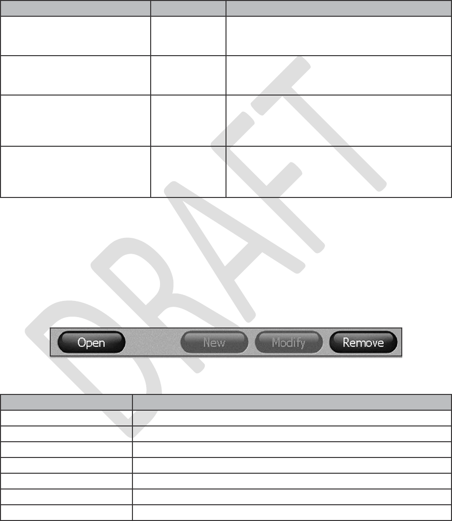
Figure 5-8. Illustrative navigation buttons.
Table 5-2. StimRouter application navigation menus, navigation tabs and
functions that can be performed from each menu/tab.
Buttons
When pressed, a navigation button will open a new screen or execute a command. See Figure
5-8. Depending on the operating mode, a button may be enabled or disabled. Disabled buttons
are GRAY. For a list of commonly used buttons, see Table 5-3.
Figure 5-8. Illustrative navigation buttons.
Chapter 5 - Device Description
27
Button
Function Descriptions
?
• Open help screens.
Change Password
• Change a user password (enabled for administrators only).
Clear
• Delete characters in a field.
Exit
• Exit the StimRouter application.
Login
• Log into the StimRouter application.
Log Off
• Log off the StimRouter application.
Modify
• Modify an existing patient record.
Menu
Tab
Function Descriptions
Tools
Info
• View system information in online mode.
• Reset the patient programmer and EPT in
online mode.
Users
• Add a new user.
• Remove a user.
• Change a user password.
Backup
• Back up the clinician programmer
database.
• Enable/disable automatic database
backup.
Restore
• Restore the clinician programmer database
from automatic backup.
• Restore the clinician programmer from
manual backup.
from one EPT to another.
(When selected, all patient data on the patient programmer
Table 5-3. Selected navigation buttons and their accompanying functions.
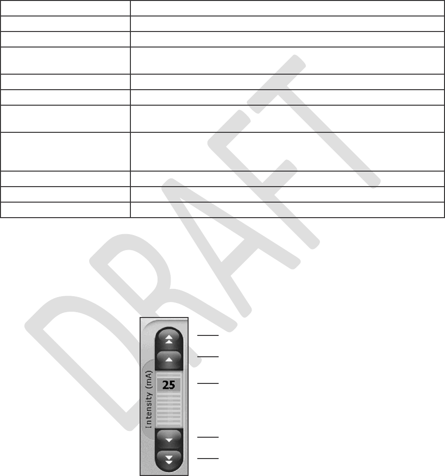
Intensity Level Bar
Used to adjust stimulation intensity. Can be adjusted while stimulation is on or off. See Figure 5-9.
Increase 5 mA
Increase 1 mA
Level Setting
Decrease 5 mA
Decrease 1 mA
Figure 5-9. Intensity level bar. To adjust intensity, press the up or down arrows.
28
Clinician’s Guide
New
• Add a new patient record.
New User
• Add a new user (enabled for administrators only).
Open
• Open an existing patient record.
Print
• Print the specified report to a Bioness-approved Bluetooth
printer or to a PDF file on the memory (SD) card.
Remove
• Remove an existing patient record.
Remove User
• Remove a user (enabled for administrators only).
Reset Patient
Programmer
• Resets the patient programmer so that it can be transferred
Reset Patient
Programmer/EPT
• Restore factory settings on the patient programmer and EPT.
and EPT are erased.)
Stop & Save
• Stop stimulation and save the stimulation and time settings.
Test
• Test the current stimulation and time settings.
View
• View session details.
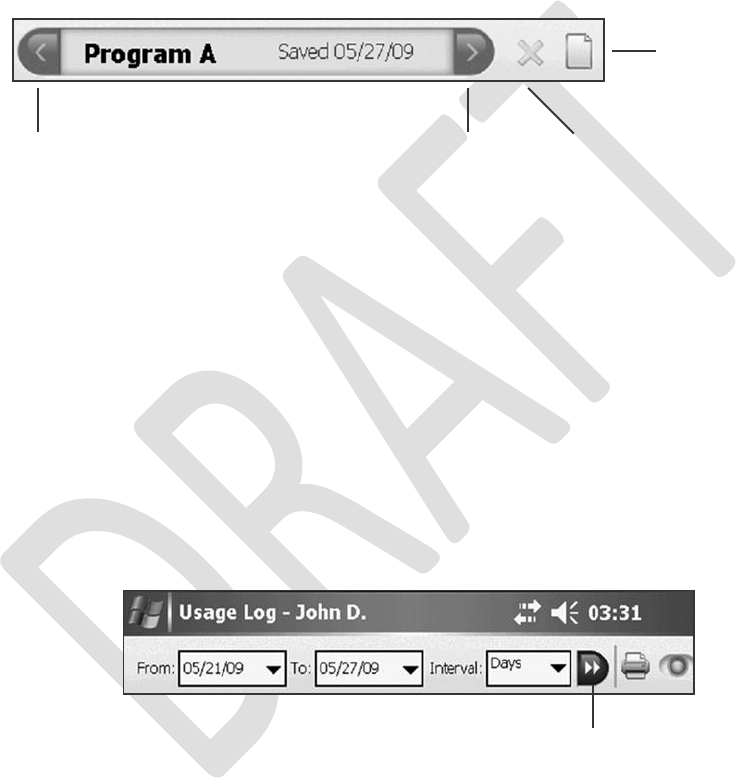
Program Bar
Used to add, delete and view up to eight clinician-set stimulation programs, labeled A-H. See
Figure 5-10.
Add Program Icon
Back Program Arrow
Next Program Arrow
Delete Program Icon
Figure 5-10. Program bar and icon definitions.
Add Program Icon. Used to add a new stimulation program. (Enabled in online mode when fewer
than eight programs have been saved.)
Delete Program Icon. Used to delete a stimulation program. (Enabled in online mode when more
than one program has been saved.)
Program Bar Arrows. Used to scroll through the saved programs. (Enabled when more than one
program has been saved.)
Search Bars
Used to search the clinician programmer database. See Figure 5-11.
Search Bars
Figure 5-11. Search bars for usage log. Select a value from the
drop-down lists or enter a value using the keyboard. Then press the double arrow to
begin the search. Press the double arrow again to view additional matches found.
Chapter 5 - Device Description
29

Programming Parameters
Patients require tailored stimulation patterns to help control their pain. The StimRouter system
features eight programmable parameters and can store up to eight stimulation programs on the
clinician programmer, patient programmer and EPT. Timing parameters are specified in Table
5-4. Pulse parameters are specified in Table 5-5.
Table 5-4. Timing parameters.
30
Clinician’s Guide
Parameter
Specification
Pulse
Balanced biphasic (pulse is hardware balanced — no DC
component exists)
Waveform
Symmetric or Asymmetric
Intensity*
0-30 milliamperes peak, 1-milliampere resolution (positive
phase)
Maximum Voltage
100 volts
Maximum Output
7 milliamperes root mean square, 40 volts root mean
square
Maximum Charge Allowed
10 microcoulombs per phase
Electrode Current Density
Less than 1 milliampere root mean square per
centimeter2
Positive Phase Duration**
70, 100, 150, 200, 250, 300, 350, 400, 450, 500
microseconds
Negative Phase Duration
Symmetric: Identical to the positive phase duration.
Asymmetric: Four times the positive phase duration.
Parameter
Definition
Specification
On Time
Time that stimulation is
applied per cycle
1-60 seconds, 1-second
resolution
Off Time
Time that stimulation is
turned off per cycle
0-60 seconds, 1 second
resolution (0 seconds =
constant stimulation)
Ramp Up
Time to increase stimulation
from zero to the set intensity
0-10 seconds, but not more
than “On time”, 1- second
resolution
Total Time
Duration from the initiation
to the end of a stimulation
program
10 minutes- 12 hours

Table 5-5. Pulse parameters.
Chapter 5 - Device Description
31
*Intensity: A measure of strength of the stimulation.
**Positive phase duration: A measure of the duration of a pulse.
***Pulse repetition rate: The number of times per second a pulse is delivered.
Parameter
Specification
Total Pulse Duration
Up to 2550 microseconds (depends on waveform)
Maximum Load
5000 ohms (subject to max voltage limitation) in parallel
to 80 nanofarads
Typical Load
2700 ohms in parallel to 22 nanofarads
Minimum Load
100 ohms in parallel to 1 nanofarad
Pulse Repetition Rate***
1, 2, 5, 10, 20, 30, 40, 50, 60, 70, 80, 90, 100, 120, 140,
160, 180, 200 hertz

32
Clinician’s Guide
6
Set-Up Instructions
Programming Components and Software
This section describes how to connect the clinician programmer and cradle, charge the clinician
programmer and launch the StimRouter application.
Connecting the Clinician Programmer and Cradle
To connect the clinician programmer and cradle:
1. Orient the clinician programmer in the configuration cradle with the touchscreen
facing up and the 24-pin connector port facing left. See Figure 6-1.
Clinician’s Programmer
Clinician Programmer
Memory Card
Charger
Clinician Programmer
24-Pin
Connector
Port
Patient Programmer
Connector
Connector Cable
Connector Cable with
Charger Adapter
Configuration Cradle
Figure 6-1. The clinician programming system set-up configuration.
Also shown is a patient programmer connected.
2. Plug the connector cable with charger adapter (on the configuration cradle) into the
24-pin connector port on the clinician programmer, with the arrows on the adapter
facing up.
Chapter 6 - Set-Up Instructions
33
Charging the Clinician Programmer
To charge the clinician programmer:
1. Insert the connector on the clinician’s programmer charger into the charger adapter on
the connector cable. See Figure 6-1.
WARNING:
Use only the
clinician’s programmer charger included
in the
StimRouter
Clinician
Kit (Manufacturer Model No. PHIHONG, PSC11R/PSM11R).
2. Plug the charger into a power socket.
3. Allow the
clinician programmer
to
charge.
The
clinician programmer
can take two to four
hours to charge. When the clinician programmer is fully charged, the indicator light next
to the On/Off button will be GREEN.
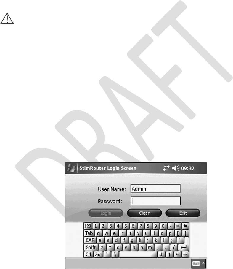
Logging into the StimRouter Application
To log into the StimRouter application:
1.
Turn the clinician programmer on by pressing the on/off button on the lower right corner
of the clinician programmer. See Figure 6-2.
If the login screen does not open automatically, then, using the stylus, press “Start” and
then “StimRouter” to open the StimRouter application. Wait for the login screen to load.
See Figure 6-2.
2.
Figure 6-2. The StimRouter application login screen.
34
Clinician’s Guide
3. To log in, enter a user name and password, and then press “Login.”
Note:
Always log
off
the StimRouter application before leaving the clinician programmer unattended.
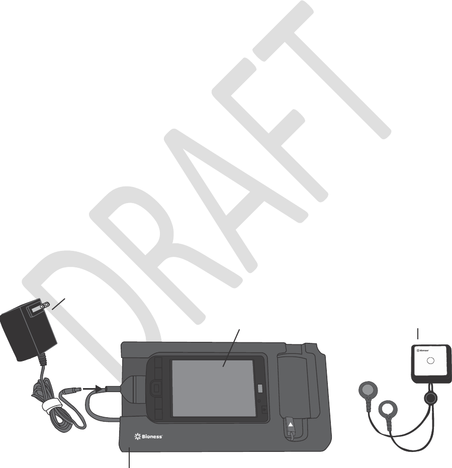
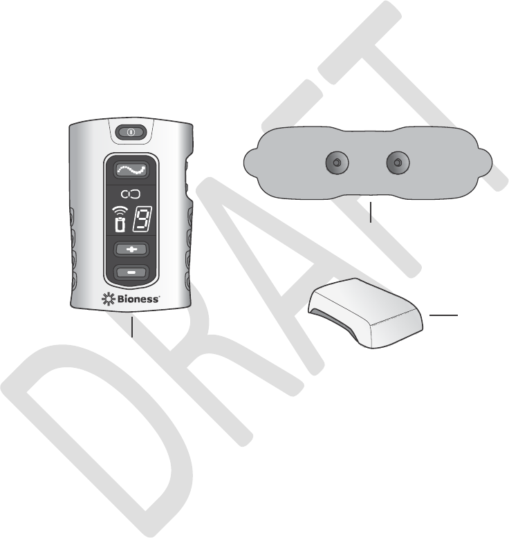
Patient’s External Components
The patient-operated components of the StimRouter system are: the patient programmer, EPT
and StimRouter electrode. See Figure 6-3.
StimRouter Electrode
EPT
Patient Programmer
Figure 6-3. The StimRouter patient programmer, StimRouter electrode and EPT.
The StimRouter User Kit also provides a system charger set to charge the patient programmer
and EPT.
When the clinician programmer is connected to an operational patient programmer and EPT, the
clinician programmer is online and ready to program.
Chapter 6 - Set-Up Instructions
35
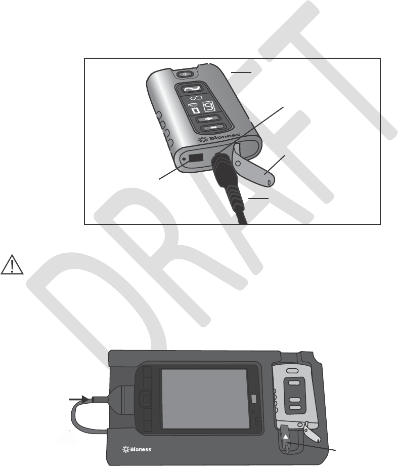
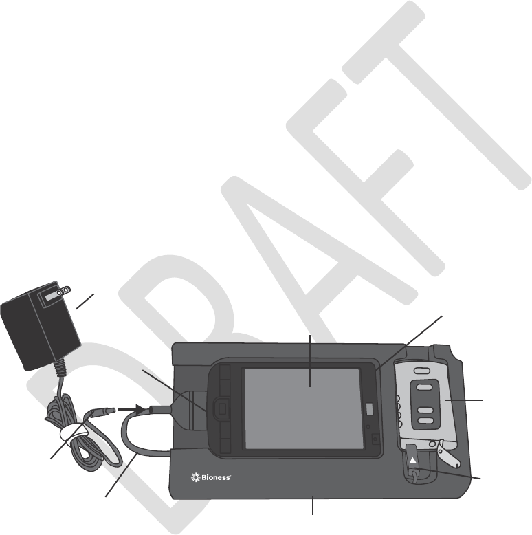
Connecting the Patient Programmer and Configuration Cradle
To connect the patient programmer and configuration cradle:
1.
2.
Open the flexible cover on the patient programmer.
If necessary, charge the patient programmer using the system charger set provided in
the User Kit. Insert the Y cable connector into the charging socket; plug the charger into
a power socket. See Figure 6-4.
Figure 6-4. Charging the patient programmer.
WARNING:
Use only the
charger included
in the
StimRouter
User Kit.
(Refer
to Manufacturer
Model No. FRIWO FW7333SM/05 or FRIWO FW7333CM/05).
3. Plug the connector cable of the configuration cradle into the connector port of the
patient programmer. The white arrow should be facing up. See Figure 6-5.
Connector Cable
Figure 6-5. Patient programmer connection configuration.
36
Clinician’s Guide
Patient Programmer
Charging Socket
Flexible Cover
Connection Port Charger Cable
Connector
4. Insert the patient programmer into the configuration cradle.
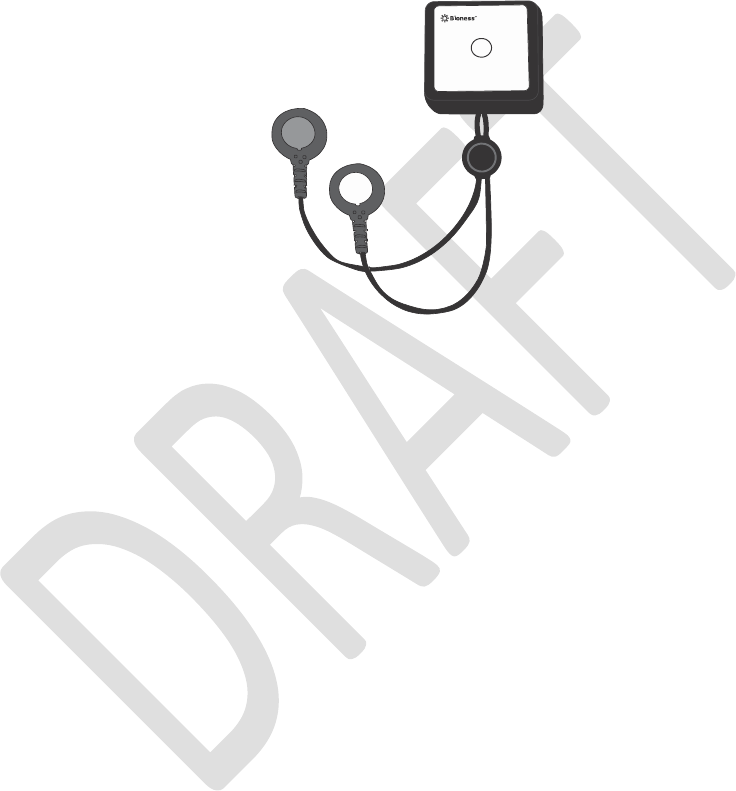
Connecting the StimRouter Electrode and EPT
To connect the StimRouter electrode and EPT:
1.
Obtain an operational StimRouter electrode. Electrodes can be reused for as long as
the gel electrodes can fully adhere to the skin.
Do not remove the the reusable StimRouter electrode liner from the gel electrodes at
this time.
Set the StimRouter electrode on a flat surface with the gel electrodes facing down.
Snap the EPT into the StimRouter electrode. See Figure 6-6.
2.
3.
4.
Figure 6-6. StimRouter electrode and EPT connection.
Note: To ensure proper electrical stimulation, the EPT must be connected to the StimRouter
electrode properly.
If the
EPT does
not work
properly,
then
remove
it from the
StimRouter
electrode
and reconnect it, or connect it to a new electrode.
Chapter 6 - Set-Up Instructions
37
EPT
StimRouter Electrode

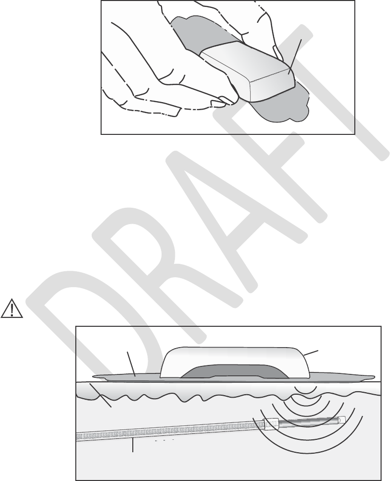
Adhering the StimRouter Electrode to the Skin
The StimRouter electrode with EPT attached should be placed on the skin directly over the
receiver end of the lead. For optimal stimulation, the skin where the StimRouter electrode will
adhere should be clean and dry. This section describes how to prepare the skin, and how to
adhere and remove the StimRouter electrode.
Note: Transfer the EPT to a new StimRouter electrode when the gel electrodes adherence to
the skin decreases..
To prepare the skin:
1.
2.
Locate the area where the receiver end of the lead is implanted.
Clean the skin above the receiver end of the lead with an alcohol swab or wet
washcloth, and then dry. If the area has been treated with lotions or oils, then clean the
skin with soap and water until all oils are removed, rinse well and dry.
If necessary, remove excess body hair from the skin area using scissors. Do not use a
razor. A razor can irritate the skin.
3.
WARNING: Do not touch the gel electrodes with both hands while stimulation is turned on.
Serious injury could result from electrical current passing across the chest cavity. Stimulation
should be turned off before adhering, removing or handling the StimRouter electrode.
WARNING: Do not apply the StimRouter electrode to anyone else or any other part of the
body than that determined by the prescribing physician. The StimRouter electrode is for single
patient use.
38
Clinician’s Guide

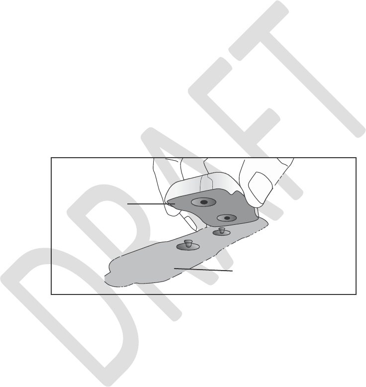
To adhere the StimRouter electrode:
1.
2.
Remove the reusable StimRouter
electrode liner and store it in the StimRouter electrode carrying case. The StimRouter
electrode liner is larger than the electrode and is marked with the Bioness logo. See
Figure 6- 8. Do not bend, break or soil the StimRouter electrode liner.
Figure 6-8. Remove the StimRouter electrode liner.
3.
Visually inspect the gel electrodes. Make sure the gel is smooth and attached to the
StimRouter
electrode.
The gel should align with the contour of the StimRouter electrode
and completely cover the base of the StimRouter electrode. Make sure the gel
electrodes are not dry.
Chapter 6 - Set-Up Instructions
39
Protective Covers
4.
Using the index finger and thumb, grasp the edges of the StimRouter electrode so that
the gel electrodes face away from the palm. See Figure 6-9.
Figure 6-9. Grasp the edges of the EPT attached to the StimRouter electrode.
5.
Align one end of the StimRouter electrode with EPT attached directly over the receiver
end of the lead. If the StimRouter electrode is not directly over the receiver end of the
lead, then stimulation may be uncomfortable or ineffective. See Figure 6-10. The
effectiveness of the stimulation is sensitive to the alignment and rotation of the
StimRouter electrode in relation to the receiver end of the lead. If the alignment or
rotation of the StimRouter electrode changes, the stimulation intensity may need to be
adjusted.
Position
the other end of the
StimRouter electrode where
it will
minimize discomfort
and
avoid muscle contractions.
6.
CAUTION: Do not pinch or stretch the skin while adhering the StimRouter electrode.
EPT
Electrode
Figure 6-10. Optimal stimulation, position of the StimRouter electrode. (Illustration not to scale.)
40
Clinician’s Guide
StimRouter
Skin
Lead Receiver End of Lead
EPT

CAUTION: Make certain the adhesion site is free of obstructions (for example, bandages,
clothing, etc.) before adhering the StimRouter electrode. If the StimRouter electrode is placed
partially or wholly over a bandage or other obstruction, then skin irritation or tissue damage could
occur during stimulation.
7. Firmly adhere the StimRouter electrode to the skin, making sure that the electrode is in
full contact with the skin. If the StimRouter electrode is not firmly adhered to the skin
and moves, then stimulation may become uncomfortable or ineffective.
8. Make certain that the patient programmer is within 10 feet of the StimRouter electrode
(with EPT attached).
Confirming Set-Up
If the clinician programmer, patient programmer, EPT are connected correctly, the clinician
programmer information icon will be GREEN, confirming online mode.
To confirm the clinician programmer is in online mode:
1.
2.
Check that the information icon on the clinician programmer is GREEN.
If the information icon is not GREEN, make certain that the StimRouter electrode with
the EPT attached is within 10 feet of the patient programmer.
If the
information
icon is still not
GREEN, check
all
connections
and charge the patient
programmer and the EPT.
Test the EPT using the tester.
See the “Troubleshooting” section of this guide.
3.
4.
5.
6.
Refer to the StimRouter User’s Guide for additional operational instructions for the StimRouter
patient programmer, EPT and StimRouter electrode, including instructions on how to:
•
•
•
•
•
Turn on the patient programmer.
Charge the patient programmer.
Adjust the volume of audio alerts on the patient programmer.
Select a stimulation program using the patient programmer.
Turn stimulation on using the patient programmer.
Chapter 6 - Set-Up Instructions
41
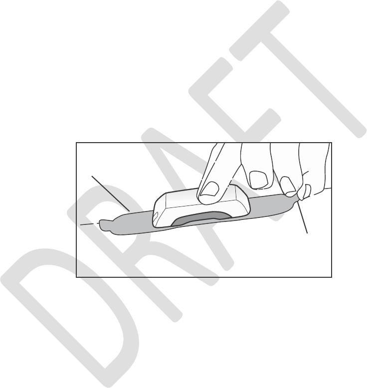
•
•
•
Adjust stimulation intensity using the patient programmer.
Save a new stimulation intensity level on the patient programmer.
Turn stimulation off using the patient programmer.
Removing the StimRouter Electrode from the Skin/Body
It may be necessary during set up to remove the StimRouter electrode to reposition it or test
the EPT.
To remove the StimRouter electrode:
1.
To remove the StimRouter electrode, make certain that stimulation is turned off. Then
grasp the tab on the StimRouter electrode and gently pull away from the skin. See
Figure 6-13.
Figure 6-13. Removing the StimRouter electrode.
2.
Obtain a StimRouter electrode liner to protect the gel electrodes from drying out. Attach
the liner to the gel electrodes.
Store the StimRouter electrode with the liner attached in the StimRouter electrode
carrying case.
3.
42
Clinician’s Guide
StimRouter Electrode
Tab
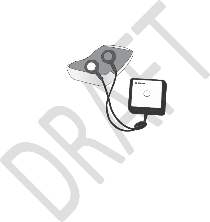
Testing the EPT
The tester is used to test the functionality of an EPT. Before connecting the EPT to the tester,
make
sure the
EPT
is
charged. Using
the
patient programmer
or
clinician programmer,
stimulation
can be turned on.
Using the tester:
1.
Connect the Tester snaps to the EPT plug holes. See Figure 6-14.
Figure 6-14. Connecting the tester to the EPT.
2.
3.
Press the patient programmer on/off button to turn on the system.
Press the mode button briefly to start stimulation, you should hear a buzzing coming from
the tester when stimulation is on and no buzzing when stimulation is off.
En
Chapter 6 - Set-Up Instructions
43

44
Clinician’s Guide

7
Patient Records and History
Patient Records
This section reviews how to add, copy, open, modify, remove and search for a patient record;
and how to view and print a patient’s session and usage history.
Definition of Terms
Unassigned System: No patient data are stored on the EPT or patient programmer.
Assigned System: Patient data are stored on either the EPT or patient programmer.
Adding a Patient with an Unassigned System
Follow these instructions when a patient does not have a record in the clinician programmer
database and no patient data have been stored on the EPT or patient programmer, i.e., the
patient’s system is unassigned and the patient is new.
Note: “New” is only enabled in online mode when the clinician programmer is connected to an
unassigned StimRouter patient programmer and EPT.
To add a patient with an unassigned system to the clinician programmer database:
1. Make certain that the clinician programmer is connected to an operational patient
programmer and EPT. See “Set-Up Instructions” section of this guide.
2. If the EPT and patient programmer are unassigned, then the application should
automatically prompt that no patient data were found on the system. Press “OK.” See
Figure 7-1.
Chapter 7 - Patient Records and History
45
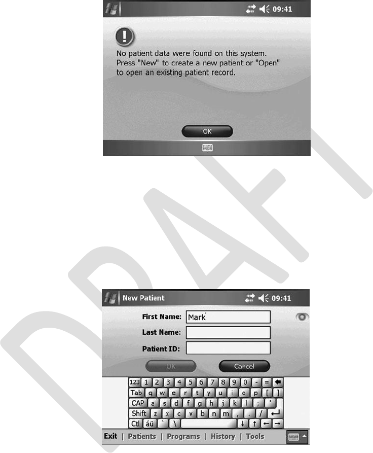
Figure 7-1. Unassigned system detected.
3.
If this prompt does not appear and the patient’s components are new, then reset the
patient
programmer
and EPT. See “Resetting the Patient
Programmer
and EPT” section
of this guide.
Press “New” to create a new patient record.
When the New Patient screen opens, enter the patient’s first and last names and a
patient ID. See Figure 7-2.
4.
5.
Figure 7-2. Adding a patient with an unassigned system.
6.
Proceed to “Programming Instructions” section of this guide.
46
Clinician’s Guide

Copying a Record for an Existing Patient to an Unassigned System
Follow
these
instructions when
a
patient
has a
record stored
in the
clinician programmer
database
and no patient data have been stored on the EPT or patient programmer, i.e., the patient is not
new but the patient’s system is unassigned. This patient may have purchased replacement
components, or the patient’s components may have been reset.
To copy a record for an existing patient to an unassigned system:
1.
Make certain that the clinician programmer is connected to an operational patient
programmer and EPT. See “Set-Up Instructions” section of this guide.
If the EPT and patient programmer are unassigned, the StimRouter application should
automatically prompt that no patient data were found on the system. Press “OK.” See
Figure 7-1.
If this prompt does not appear and the patient’s components are new, then reset the
patient programmer and EPT. See “Tools” section of this guide.
Find the patient’s record on the Patient List, and then press “Open.” When the patient
record opens, the patient data will automatically copy from the clinician programmer to
the EPT and patient programmer.
2.
3.
4.
Chapter 7 - Patient Records and History
47
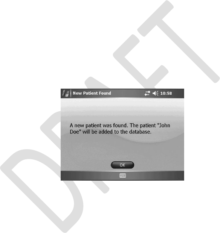
Adding a Patient with an Assigned System
Follow these instructions when a patient does not have a record in the clinician programmer
database but data are stored on the patient’s EPT and patient programmer, i.e., the patient’s
system is assigned. This patient may be a referral from another clinic or from a clinician using a
different clinician programmer.
To add a patient with an assigned system to the clinician programmer database:
1.
Make certain that the clinician programmer is connected to an operational patient
programmer and EPT. See “Set-Up Instructions” section of this guide.
The StimRouter application will automatically prompt that a new patient was found and
add the patient to the clinician programmer database. See Figure 7-3.
Proceed to “Programming Instructions” section of this guide.
2.
3.
Figure 7-3. Adding a patient with an assigned system.
48
Clinician’s Guide
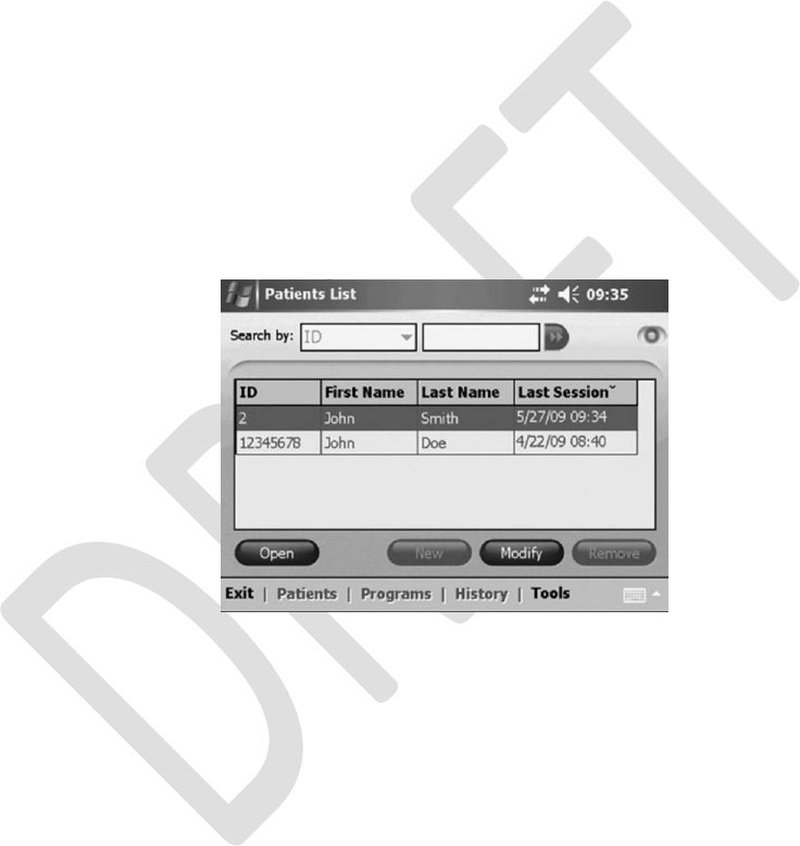
Opening a Patient Record
Note: When the clinician programmer is in online mode and connected to a patient programmer
and an EPT that contain programs, only the patient record corresponding to those components
can be opened. If the components do not contain programs, then any patient record can be
opened and the patient data copied to the patient programmer and EPT. In offline mode, any
patient record can be opened and viewed.
To open a patient record:
1.
2.
Press the PATIENTS MENU to open the Patient List.
Select a patient from the Patient List, and then press “Open.” See Figure 7-4.
Figure 7-4. Opening a patient record.
Note: If a patient programmer and EPT are connected to the clinician programmer and have
programs stored on them, then only the corresponding patient record can be opened.
Chapter 7 - Patient Records and History
49

Modifying a Patient Record
Note: “Modify” is only enabled in online mode, when the clinician programmer is connected to
a working patient programmer and EPT.
To modify a patient record:
1.
2.
3.
Press the PATIENTS MENU to view the Patient List.
From the Patient List, press “Modify.”
Enter changes to the patient’s first or last name, and then press “OK.” See Figure 7-6.
Patient ID cannot be modified.
Figure 7-6. Modifying a patient record.
Removing a Patient Record
Note: “Remove” is only enabled in offline mode.
To remove a patient record:
1.
Make certain that the clinician programmer is not connected to an operational patient
programmer and EPT, i.e., that the clinician programmer is in offline mode. The
information icon should not be GREEN.
Press the PATIENTS MENU to open the Patient List, select the patient record to
remove, and then press “Remove.” See Figure 7-7.
2.
50
Clinician’s Guide
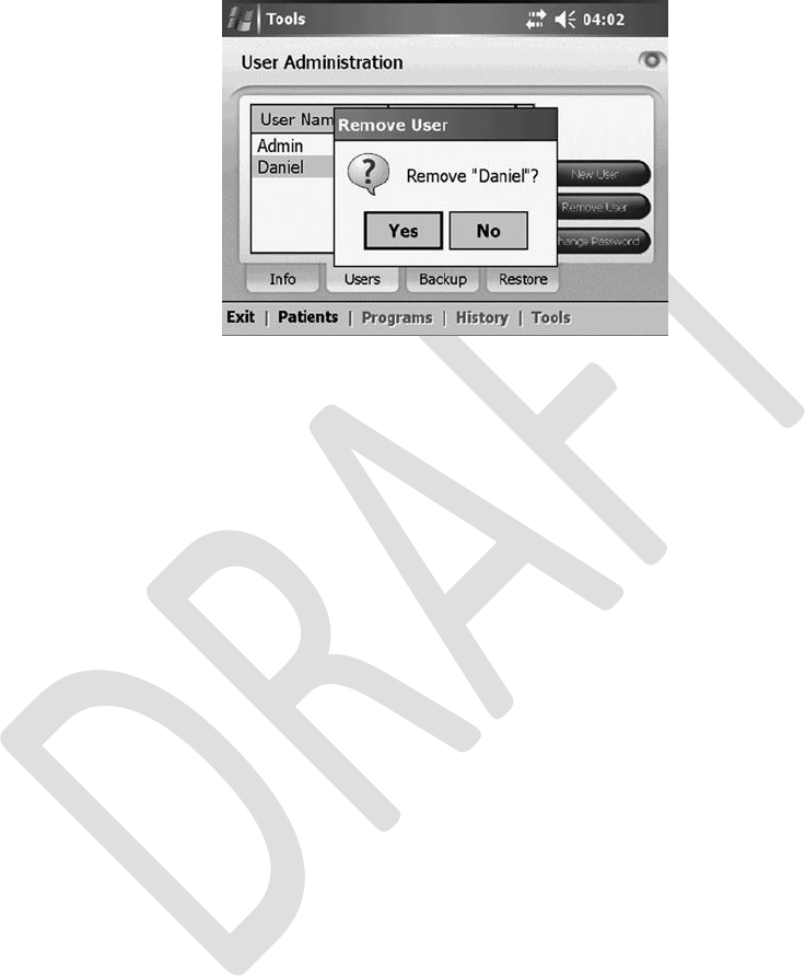
Figure 7-7. Removing a patient record.
Searching for a Patient Record
To search for a patient record:
1.
Make certain that the clinician programmer is not connected to an operational patient
programmer and EPT, i.e., that the clinician programmer is in offline mode. The
information icon should not be GREEN.
Press the PATIENTS MENU to open the Patient List.
Using the search bar, select a search criterion from the “Search by” drop- down list,
enter the search data in the accompanying field, and then press the double arrow to
start the search.
The first match found (if any) will be highlighted on the Patient List.
Press the double arrow again to view any additional matches found.
2.
3.
4.
5.
Chapter 7 - Patient Records and History
51
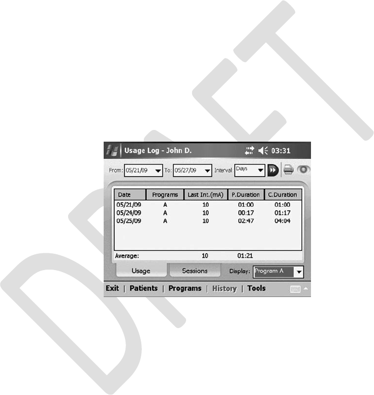
Usage History
The patient usage history is stored on the EPT and is automatically retrieved when the clinician
programmer is connected to an operational patient programmer and EPT.
Viewing a Usage History
To view a usage history:
1.
2.
3.
From the PATIENTS MENU, select the patient on the Patient List, and then press “Open.”
From the HISTORY MENU, press the USAGE TAB to open the Usage Log.
In the “Display” drop-down list (bottom right of screen), select a program to view or
select “All Programs.” See Figure 7-8.
Figure 7-8. Sample usage log for program A.
Note:
Last Int. - Intensity in mA when the system was turned off the last time that interval.
P. Duration - Program duration. How long that program was used in that interval.
C. Duration - Cumulative duration. The total of the program durations.
Average - Average of the program duration per interval.
4.
In the “From,” “To” and “Interval” drop-down lists (top of screen), select a from date, a
to date and an interval for viewing, and then press the double arrow. The usage history
will open.
52
Clinician’s Guide
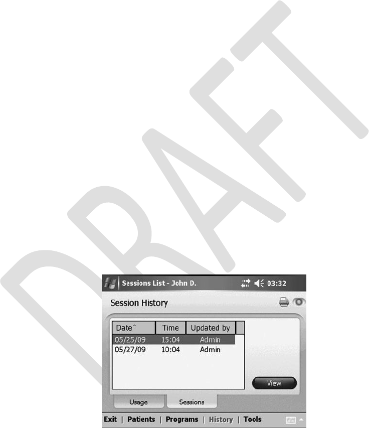
Printing a Usage History
To print a usage history:
1. Press the print icon on the Usage Log screen.
2. From the “Printer” drop-down list, select the installed printer or “Adobe PDF file,” and
then press “Print.”
Note:
Selecting “Adobe PDF file” saves the usage history
as a
PDF
file on
the clinician
programmer
memory (SD) card.
Session History
Session history can be viewed and printed from the
SESSIONS
TAB under the
HISTORY
MENU.
Open a patient record to enable the HISTORY MENU.
Viewing a Session History
To view a session history:
1.
2.
From the PATIENTS MENU, select the patient on the Patient List, and then press “Open.”
From the HISTORY MENU, press the SESSIONS TAB, select a session to view, and
then press “View.” See Figure 7-9.
Figure 7-9. Viewing a session.
Chapter 7 - Patient Records and History
53
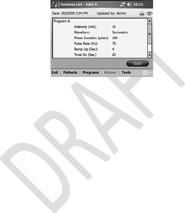
3.
The session detail will open. See Figure 7-10.
Figure 7-10. Session detail.
Printing a Session History
To print a session history:
1. With the session detail open, press the print icon.
2. From the “Printer” drop-down list, select the installed printer or “Adobe PDF file,” and
then press “Print.”
Note: Selecting “Adobe PDF file” saves the session as a PDF file on the clinician programmer
memory (SD) card.
Printing Multiple Sessions
To print multiple sessions:
1.
2.
3.
Open the SESSIONS TAB.
Press the print icon.
When the Print Sessions screen opens, check the box next to each session to be
printed, and then press “Print.” See Figure 7-11.
From the “Printer” drop-down list, select the installed printer or “Adobe PDF file,” and
then press “Print.”
4.
54
Clinician’s Guide
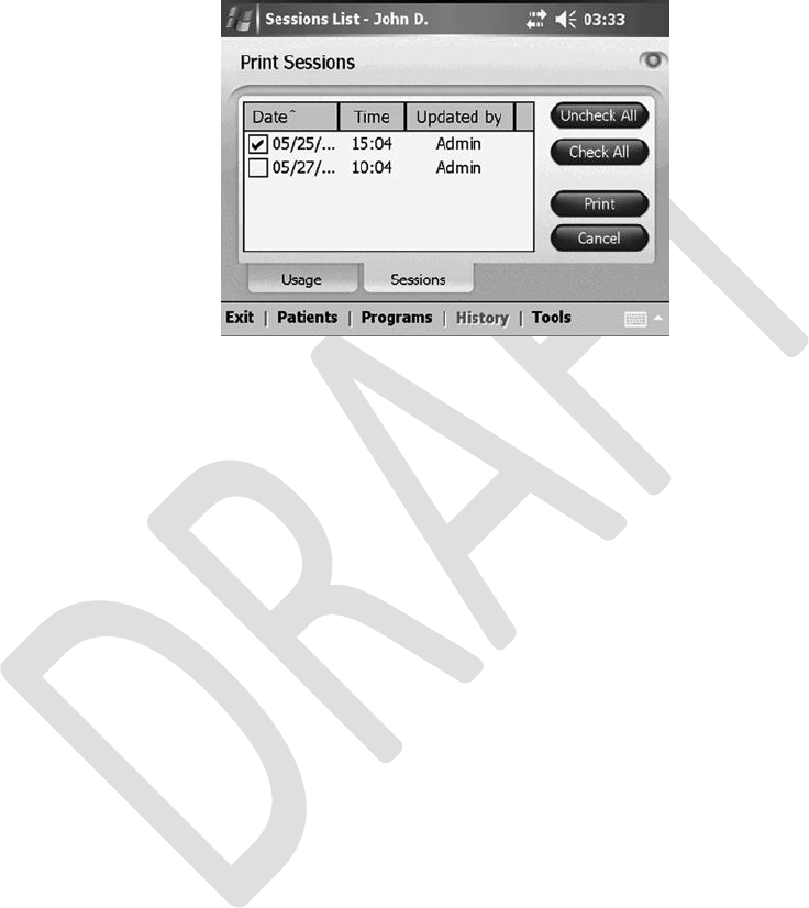
Note: Selecting “Adobe PDF file” saves the session as a PDF file on the clinician programmer
memory (SD) card.
Figure 7-11. Printing multiple sessions. Check which sessions to print, and then press “Print.”
Chapter 7 - Patient Records and History
55

56
Clinician’s Guide
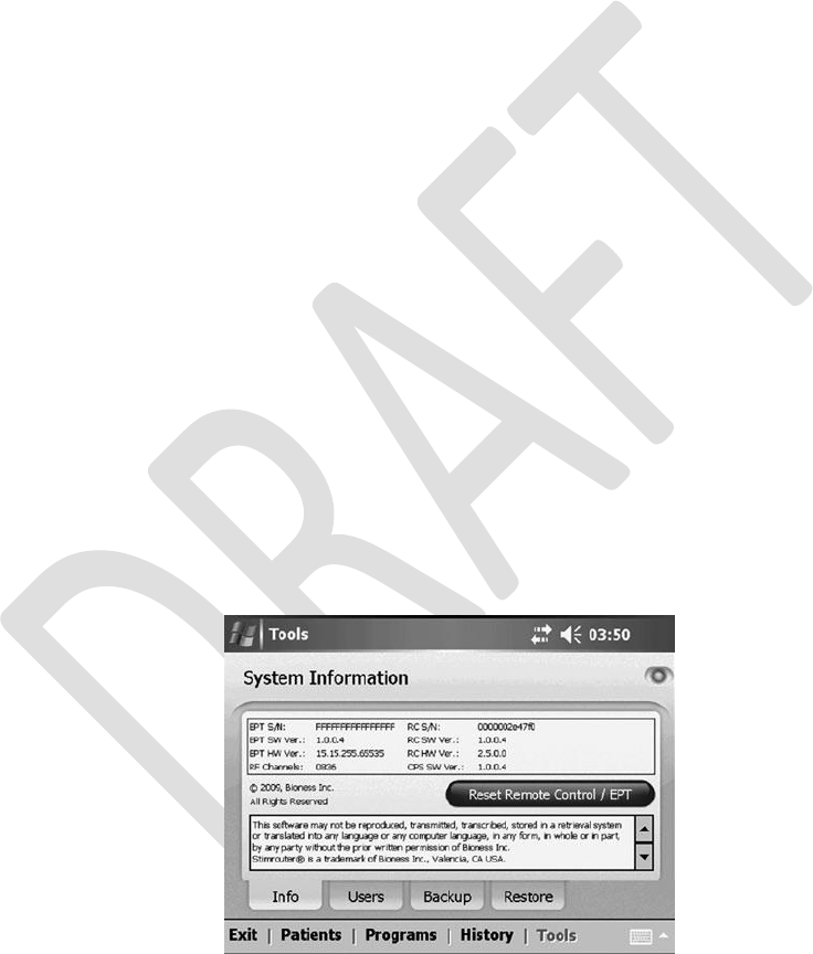
8
Tools
Both users and administrators have access to the INFO TAB of the TOOLS MENU. Only
administrators
have access to the USERS, BACKUP and RESTORE tabs of the TOOLS MENU.
System Information and Component Reset
System information can be found on the INFO TAB of the TOOLS MENU. From the INFO TAB,
users can also reset the patient programmer, if, for example, a clinic patient programmer is to
be used. Users can also reset the patient programmer and EPT, which restores the components
to their factory settings. All patient data and logs are deleted.
Resetting the Patient Programmer and EPT
To reset the patient programmer:
1.
2.
Connect the patient programmer to the configuration cradle.
Press the TOOLS MENU, and then, on the INFO TAB, press “Reset Patient
Programmer/EPT.” See Figure 8-1.
Figure 8-1. Resetting the patient programmer and EPT.
3.
Select “Reset the Patient Programmer,” and then press “Reset.” See Figure 8-2.
Chapter 8 - Tools
57
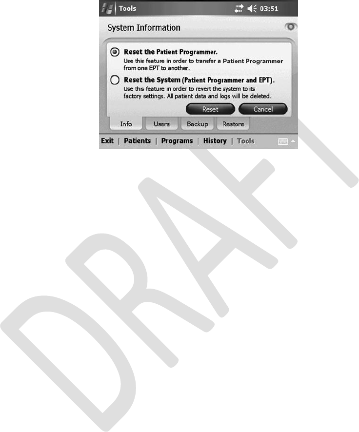
Figure 8-2. Select a reset option, and then press “Reset.”
To reset the patient programmer and EPT:
1. Make certain the clinician programmer is in online mode. Select “Reset the System
(Patient Programmer and EPT),” and then press “Reset.” See Figure 8-2.
User Administration
The
StimRouter application supports
two
levels
of
users: users
and
administrators.
Administrators
have extended authorizations. Administrators can define automatic backup options, manually
back up the clinician
programmer
database, manually restore the clinician
programmer database,
add and remove users/administrators, and change user passwords.
58
Clinician’s Guide
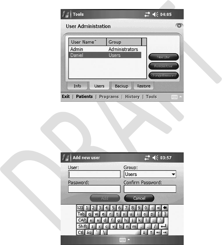
Adding a User/Administrator
To add a user/administrator:
1.
From the TOOLS MENU, press the USERS TAB and then “New User.” See Figure 8-3.
Figure 8-3. Adding a user/administrator.
2.
Enter a user name and password, confirm the password, select either “Users” or
“Administrators” from the “Group” drop-down list, and then press “Add.” See Figure 8-4.
Figure 8-4. Adding a user/administrator.
Chapter 8 - Tools
59
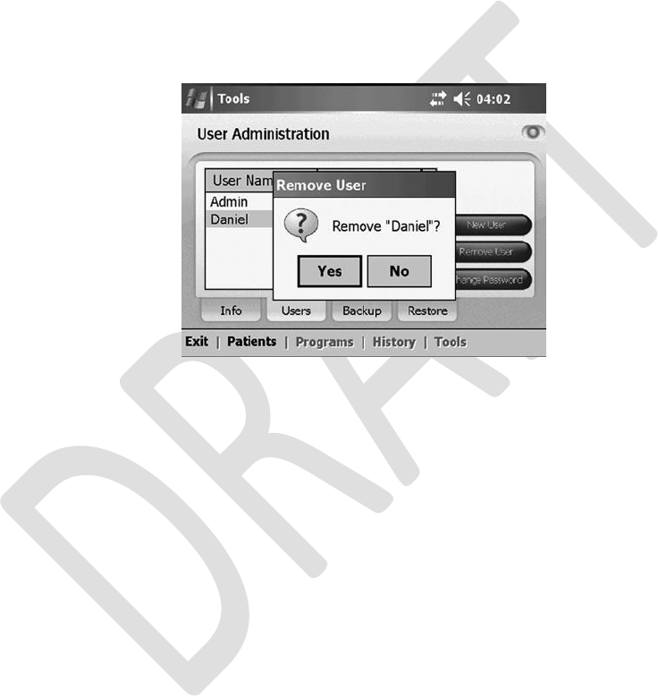
Removing a User/Administrator
To remove a user/administrator:
1.
From the TOOLS MENU, press the USERS TAB, select a user name, and then press
“Remove User.” Confirm “Yes” or “No” when prompted. See Figure 8-5. (The
administrator who is logged on cannot be removed.)
Figure 8-5. Removing a user. Select the user, and then press “Remove.”
60
Clinician’s Guide
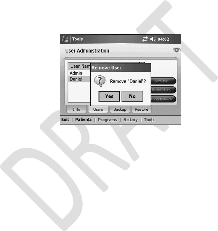
Changing a User Password
To change a user password:
1.
From the TOOLS MENU, press the USERS TAB, select a user name, and then press
“Change Password.”
Enter and confirm the new user password, and then press “OK.” See Figure 8-6.
2.
Figure 8-6. Changing a user password.
Note: Bioness recommends that passwords be changed at least every three months.
Chapter 8 - Tools
61
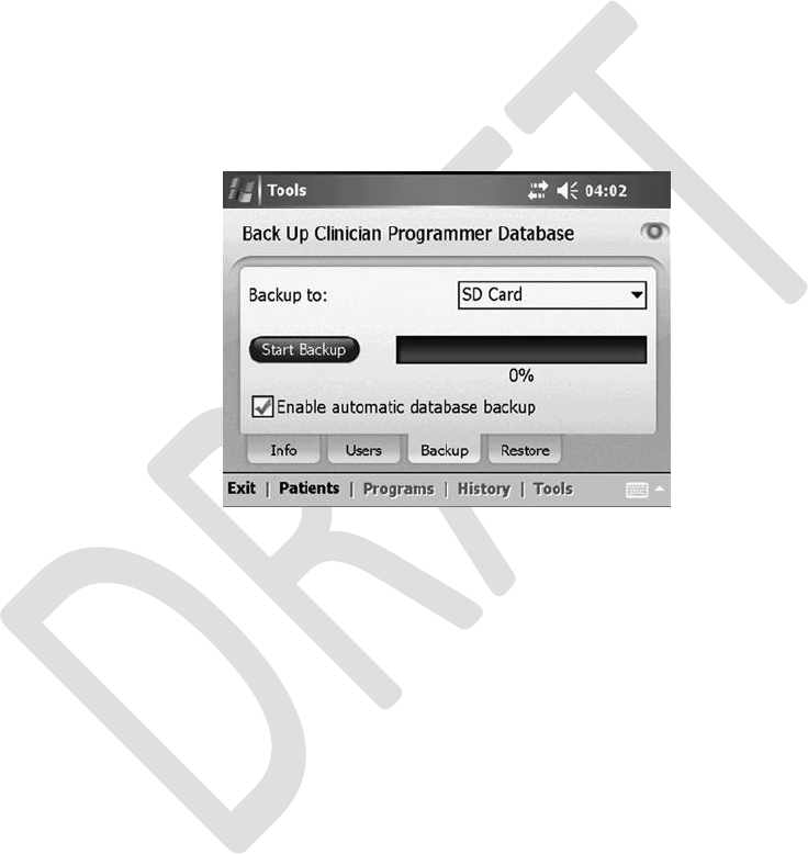
Clinician Programmer Database Backup and Restore
Manually Backing Up the Database
Note: Only administrators have access to the BACKUP TAB.
To manually back up the clinician programmer database:
1.
From the TOOLS MENU, press the BACKUP TAB. See Figure 8-7.
Figure 8-7. Backing up the clinician programmer database.
2.
From the “Back up to” drop-down list, select “SD Card,” and then press “Start Backup.”
Enabling Automatic Database Backup
To enable automatic database backup:
1. From the TOOLS MENU, press the BACKUP TAB, and then check “Enable automatic
database backup.” The clinician programmer database will back up once per day and
each time the application is exited. See Figure 8-7.
62
Clinician’s Guide
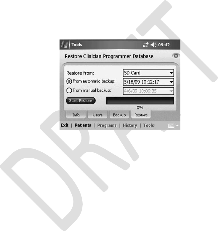
Restoring the Database
Note: Only administrators have access to the RESTORE TAB.
To restore the clinician programmer database:
1.
2.
From the TOOLS MENU, press the RESTORE TAB.
From the “Restore from” drop-down list, select “SD Card.”See Figure 8-8.
Figure 8-8. Restoring the clinician programmer database.
3.
Select “From automatic backup” or “From manual backup,” and then choose a backup
date and time from the drop-down lists.
Press “Start Restore.”
4.
Chapter 8 - Tools
63

64
Clinician’s Guide
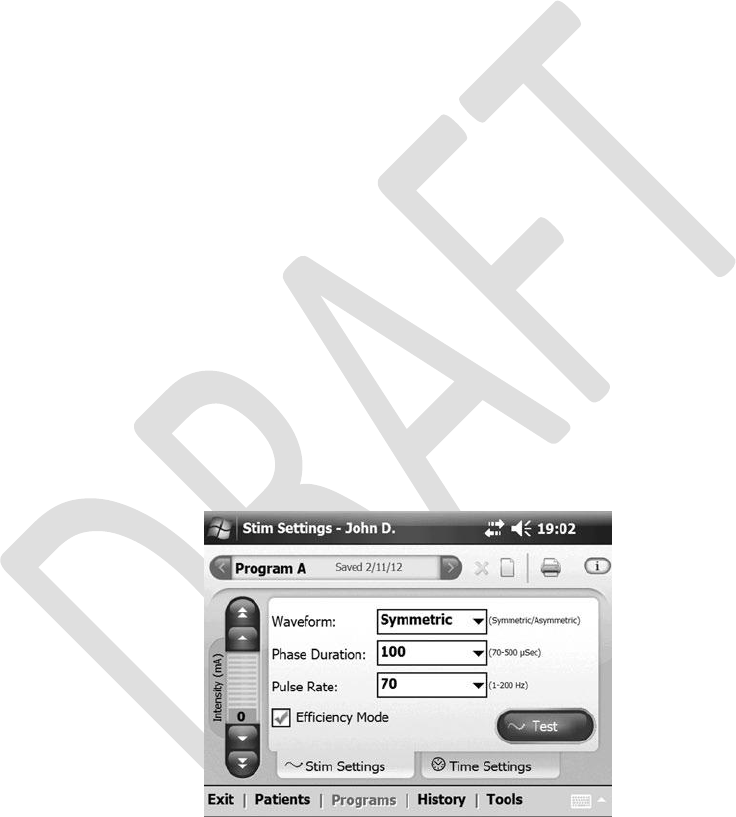
9
Programming Instructions
The
programming session
can
begin once
the
StimRouter electrode
with
EPT attached
is adhered,
the clinician programmer and patient programmer are set up, and the patient’s record is added
and opened. This section describes how to program stimulation and time settings, and how to
add a program, view a program, delete a program and print a program.
Stimulation and Time Settings
Programming Stimulation Settings
To program stimulation settings:
1.
Make sure that the StimRouter application is in online mode (the information icon
should be GREEN). See “Confirming Set-Up” section of this guide.
From the PATIENTS MENU, press “Open” to view the STIM SETTINGS TAB. See
Figure 9-1.
2.
Figure 9-1. Programming stimulation settings.
3.
Adjust the stimulation settings using the drop-down lists next to “Waveform,” “Phase
Duration” and “Pulse Rate.”
Chapter 9 - Programming Instructions
65
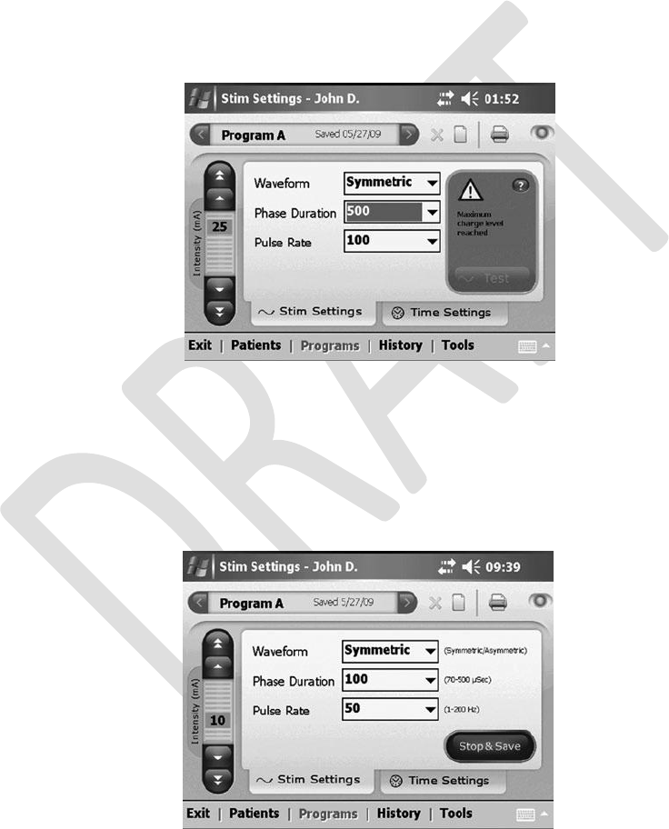
Note: The stimulation settings have a constant ramp-up of 1 second, during which the patient
may not feel any stimulation. Account for ramp-up time during the adjustment process.
4. Press “Test” to test the stimulation settings; stimulation will turn on.
Note:
If the combination of parameters exceeds the maximum charge level allowed (10 microcoulombs
per phase), then a warning will appear with directions to reduce the total charge. “Test” will be
disabled. See Figure 9-2.
Figure 9-2. Maximum charge level exceeded.
5.
Slowly increase the intensity to a level that is tolerable for the patient and achieves the
desired therapy.
Press
“Stop &
Save”
to stop
stimulation
and save the
stimulation settings
to the
clinician programmer, patient programmer and EPT. See Figure 9-3.
6.
Figure 9-3. Press “Stop & Save” to stop testing and save the current stimulation settings.
66
Clinician’s Guide
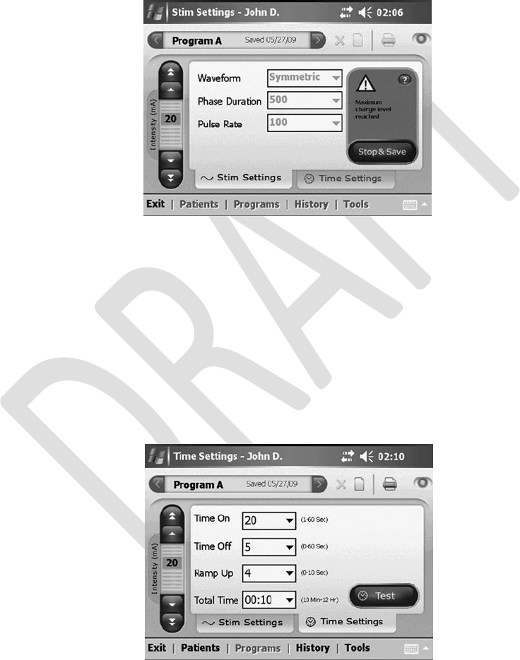
7. The program save date will appear on the Program Bar.
Note: If an intensity adjustment during testing causes the maximum charge level to be reached,
then a notification will appear. No further increase will be allowed. See Figure 9-4.
Figure 9-4. Maximum charge level reached.
Programming Time Settings
To program time settings:
1.
2.
From the STIM SETTINGS TAB, press the TIME SETTINGS TAB.
The default time setting is constant stimulation. When “Constant Stim” is checked,
“Time On” and “Time Off” are disabled; “Ramp Up” and “Total Time” can be
adjusted.
To
change the duty cycle, uncheck “Constant Stim” and adjust “Time On” and “Time Off.”
See Figure 9-5.
Figure 9-5. Programming time settings.
Chapter 9 - Programming Instructions
67

3. Press “Test” to test the time settings; stimulation will turn on.
4. Fine-tune the intensity level (using the up/down arrows).
Note: If an intensity adjustment during testing causes the maximum charge level to be reached,
then a notification will appear. No further increase will be allowed. See Figure 9-6.
Figure 9-6. Maximum charge level reached.
5. Press “Stop & Save” to stop stimulation and save the time settings to the clinician
programmer, patient programmer and EPT.
6. The program save date will appear on the Program Bar.
Programs
Delete Program Icon
Add Program Icon
Print Icon
Back Program Arrow
Next Program Arrow
Figure 9-7. Add a program icon, back program arrow,
next program arrow, delete program icon, and print icon.
68
Clinician’s Guide

Adding a Program
Note: The StimRouter application must be in online mode to add a new stimulation program.
To add a program:
1.
From the STIM SETTINGS TAB or TIME SETTINGS TAB press the add program icon
on the Program Bar. See Figure 9-7.
The new program will open with default settings. The new program label (A-H) will
appear in the Program Bar.
After the program has been tested and “Stop & Save” pressed, the program will be
saved to the clinician programmer database, the patient programmer and the EPT. The
date the program was saved will appear in the center of the program bar.
2.
3.
Note: The StimRouter can support up to eight programs, labeled A-H.
Viewing a Program
To view a program:
1. From the STIM SETTINGS TAB or the TIME SETTINGS TAB, press the left or right
arrow on the Program Bar and scroll to the desired program. If only one program is
saved, then the arrows on the Program Bar will be disabled. See Figure 9-7.
Deleting a Program
Note: The StimRouter application must be in online mode to delete a stimulation program.
To delete a program:
1. From the STIM SETTINGS TAB or the TIME SETTINGS TAB, select a program to
delete.
2. Press the delete program icon on the Program Bar. See Figure 9-7.
Chapter 9 - Programming Instructions
69
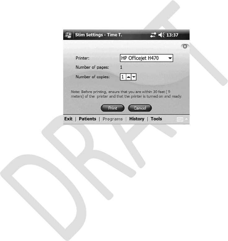
Printing a Program
To print a program:
1. Open the selected program and press the print icon. See Figure 9-7.
2. Select a printer or “Adobe PDF file” from the drop-down list, and then press “Print.” See
Figure 9-8.
Figure 9-8. Select a printer (or “Adobe PDF file”) from the drop-down list, and then press “Print.”
3.
If the page does not print, then verify that the printer is within 30 feet of the clinician
programmer, is turned on, has paper in the paper tray and is not displaying an error
message.
70
Clinician’s Guide

10
Maintenance and Cleaning
Battery Replacement
Replacing the Clinician Programmer Battery
During extended periods of nonuse, remove the battery from the clinician programmer. Refer to
the iPAQ product instructions for information on battery removal and replacement.
CAUTION: Risk of explosion if battery is replaced by an incorrect type. Dispose of used
batteries according to local regulation.
Cleaning
All StimRouter Clinician Kit components may be cleaned by carefully wiping them with a
damp cloth. Use water. Do not use detergents or other cleaning agents. Do not clean the gel
electrodes on the StimRouter electrode.
StimRouter electronic components are not waterproof; do not immerse them in water.
Disinfecting
Electronic Components
All StimRouter Clinician Kit electronic components may be cleaned and low-level disinfected
using CaviWipes™ (Metrex, Orange,
CA), or
wipes
or
cloths saturated
with 70%
isopropyl
alcohol
(IPA) per the instructions below:
1. Use one saturated disinfectant wipe or cloth to thoroughly wet the component surface.
2. Use a second saturated disinfectant wipe or cloth to remove any surface contaminants.
Soil, etc., will impede the disinfectant’s effectiveness, if not removed.
Chapter 10 - Maintenance and Cleaning
71

3. As
needed,
use
additional saturated disinfectant wipes
or
cloths
to keep the component
surface wet for 10 minutes.
Note: Be sure to follow the Bioness instructions for the specified contact time to ensure
an effective bacteria kill.
Clinician Kit Carrying Case
The StimRouter Clinician Kit carrying case may be cleaned and low-level disinfected using
CaviCide® (Metrex, Orange, CA) or 70% isopropyl alcohol (IPA) per the instructions below:
CaviCide:
1.
2.
Spray the entire surface of the Clinician Kit carrying case with CaviCide.
Use a clean towel to remove any surface contaminants. Soil, etc., will impede the
disinfectant’s effectiveness, if not removed.
Spray the entire surface of the Clinician Kit carrying case again with CaviCide.
Keep spraying the entire carrying case surface as needed to keep it wet for 10 minutes.
3.
4.
70% IPA:
1.
Wipe the entire surface of the Clinician Kit carrying case with a wipe or cloth saturated
with 70% IPA.
Use a new wipe or cloth saturated with 70% IPA to remove any surface contaminants.
Soil, etc., will impede the disinfectant’s effectiveness, if not removed.
Wipe the entire surface of the Clinician Kit carrying case again with a new wipe or cloth
saturated with 70% IPA.
Use additional new wipes or cloths as needed to keep the entire surface of the carrying
case wet with 70% IPA for 10 minutes.
2.
3.
4.
Note: Be sure to follow the Bioness instructions for the specified contact time to ensure an
effective bacteria kill.
Note: Do not use other cleaning/disinfecting agents such as a diluted bleach mixture, Lysol or
Clorox wipes. Bioness has not tested these products’ effectiveness
on
the StimRouter
components.
Metrex products are sold through authorized dealers worldwide; 70% IPA is widely available. If
you need assistance, please contact your local distributor.
72
Clinician’s Guide

11
Troubleshooting
The tables at the end of this section describe the visual indicators that may appear on the
clinician
programmer and patient programmer, and possible solutions for troubleshooting. In addition,
this section describes solutions for the following scenarios that may arise during a programming
session:
•
•
•
•
The patient forgets to bring the patient programmer.
The patient forgets to bring or has lost the EPT.
The patient brings a new patient programmer and EPT.
The patient forgets the StimRouter electrode.
Patient Forgets Patient Programmer
If a patient forgets to bring his or her patient programmer to a follow-up session, an alternate
“clinic” patient programmer can be used. The clinic patient programmer must be reset and then
registered to the patient’s EPT to proceed. Once the clinic patient programmer and patient’s EPT
are registered, patient data stored on the EPT can be retrieved by the clinician programmer and
new data can be stored on the EPT.
The patient will need to re-register his or her EPT and patient programmer later. The new data
stored on the EPT will overwrite the data stored on the patient programmer.
Note: The information stored on an EPT will always overwrite the information stored on a patient
programmer.
Chapter 11 - Troubleshooting
73
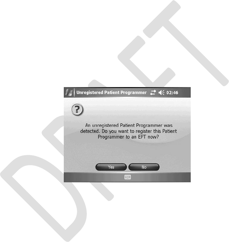
Using a Clinic Patient Programmer
To use a clinic patient programmer:
1.
2.
3.
Connect the clinic patient programmer to the clinician programmer cradle.
Make sure the EPT and the patient programmer are charged (if not, connect them to
a charger).
Make sure the patient programmer and the EPT are no more than a few inches apart
and not touching.
From the TOOLS MENU, press “Reset Patient Programmer/EPT.”
Select “Reset the Patient Programmer” and press “Reset.”
The StimRouter application will detect the unregistered patient programmer and ask
whether you want to register this patient programmer to an EPT now. See Figure 11-1.
4.
5.
6.
Figure 11-1. Unregistered patient programmer detected.
7.
8.
9.
Press “Yes.”
Once the patient programmer and EPT are registered, press “OK.”
10. From the Patient List, press “Open” to open the patient’s record.
74
Clinician’s Guide
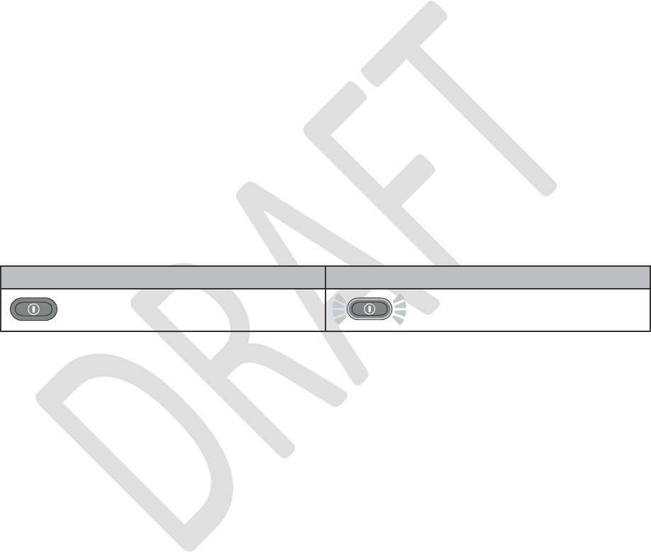
Note: The patient Usage Log is stored on the EPT and is
automatically
retrieved when the patient
programmer and EPT are connected.
11. Proceed with the programming session. Programming changes will be automatically
saved to the EPT.
12. Before the session ends, remind the patient to re-register his or her EPT and patient
programmer at home. Review with the patient the following instructions for RF registration.
Registering the Patient Programmer/EPT
The patient programmer and EPT must be electronically registered to each other to operate.
To register the patient programmer/EPT:
1.
2.
If necessary, charge the patient programmer.
Ensure that the patient programmer is turned off (the on/off button should not be
FLASHING GREEN). See Table 11-1.
Table 11-1. Patient programmer on/off indicators.
3.
4.
Make sure the EPT is charged (if not, connect the EPT to a charger).
Place the patient programmer and the EPT close together on a table. Make sure the
patient
programmer
and the EPT are no more than a few inches apart and not
touching.
Make certain that any other EPT is at least 10 feet away from the components to be
registered.
Simultaneously press and hold for three seconds the mode and minus buttons on the
patient programmer to start the registration process. See Figure 11-2. The patient
programmer will sound an audio alert, indicating the registration process has begun.
The patient programmer digital display should show two ALTERNATING GREEN
ARCHES, indicating registration is in progress.
5.
6.
7.
Chapter 11 - Troubleshooting
75
Patient Programmer OFF
Patient Programmer ON
Flashing Green
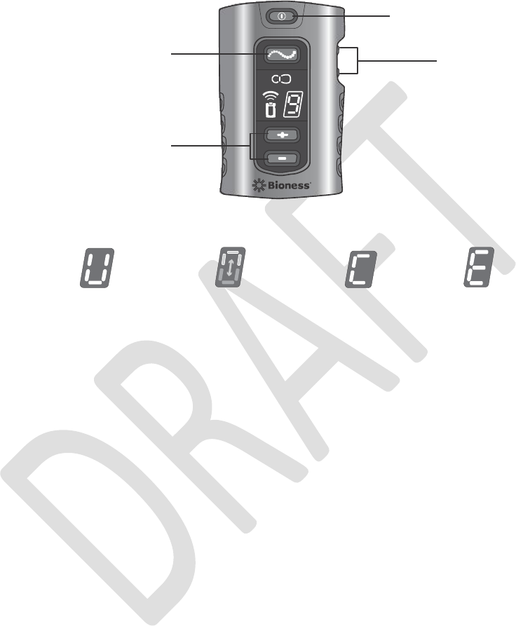
On/Off Button
Mode Button
Volume Buttons
Plus/Minus Buttons
Unregistered
In Process
Complete
Error
Figure 11-2. StimRouter Patient Programmer operating buttons and RF registration status indicators.
8. When the digital display shows the letter “C” and the RF icon turns GREEN for a few
seconds, the registration procedure is complete.
Note: If the digital display shows the letter “E” and the RF icon turns RED for a few seconds,
then an error has occurred and the procedure must be repeated. If the problem persists,
reconnect the charger to the EPT. If the error indication continues to appear, see Table 11-7.
Patient Forgets EPT
If a patient forgets to bring his or her EPT to a follow-up session, reschedule the programming
session. Do not substitute a clinic EPT for the patient’s EPT; only the patient programmer can
be substituted. The information stored on an EPT will always overwrite the information stored
on a patient programmer. If a clinic EPT is used, then the patient’s EPT will overwrite any new
information stored on the patient programmer.
76
Clinician’s Guide

Patient Loses EPT
When a patient loses an EPT, he or she will need to
electronically
register the patient programmer
and new EPT. See “Registering the Patient Programmer/EPT” section of this guide. All data
stored on the patient programmer will copy to the new EPT. However, since the usage history is
stored on the EPT, any usage history that was not copied to the clinician programmer database
is lost with the lost EPT.
Patient Brings New EPT and New Patient Programmer
If a patient receives a replacement EPT and patient programmer, then the patient will need to
return to the clinic. The patient data stored on the clinician
programmer
database must be copied
to the new EPT and patient programmer.
Copying Patient Data to New Components
To copy patient data to new components:
1.
Connect the patient programmer to the clinician programmer and the configuration
cradle.
Make sure the patient’s EPT and the patient programmer are charged (if not, connect
them to a charger).
Make sure the patient programmer and the EPT are no more than a few inches apart
and not touching.
The StimRouter application will detect the unregistered patient programmer and ask
whether you want to register this patient programmer to an EPT now.
Press “Yes.”
Once the patient programmer and EPT are registered, press “OK.”
From the Patient List, select the patient’s record and press “Open.” Once the patient
record is opened, all patient data except for history will copy to the patient’s new patient
programmer and EPT.
2.
3.
4.
5.
6.
7.
8.
Chapter 11 - Troubleshooting
77
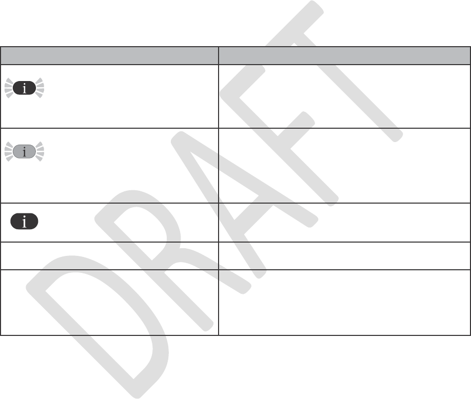
Patient Forgets StimRouter Electrode
If a patient forgets to bring his or her StimRouter electrode to a follow-up session, use a clinic
StimRouter electrode or reschedule the programming session
Troubleshooting Wireless Technology
Table 11-2. Troubleshooting, clinician programmer.
78
Clinician’s Guide
Clinician Programmer
Problems/Solutions
FLASHING RED Information
Icon
A User-Correctable Error such as Faulty
Electrode Contact, Radio Communication
Failure
• Press the information icon to view the error
message and list of solutions.
FLASHING YELLOW
Information Icon
Low Battery Detected: EPT or Patient
Programmer
• Press the information icon to view the error
message and list of solutions.
• Charge the patient programmer.
• Charge the EPT.
RED Information Icon
Software or Hardware Error
• Press the information icon to view the error
message and list of solutions.
Unexpected Error in the StimRouter
Application
Contact your local distributor.
Clinician Programmer Will Not Turn On
• Press the clinician programmer reset button.
• Charge the clinician programmer and verify
that the amber LED is ON. If the light does not
turn on, refer to the HP instructions for use.
• Contact your local distributor.
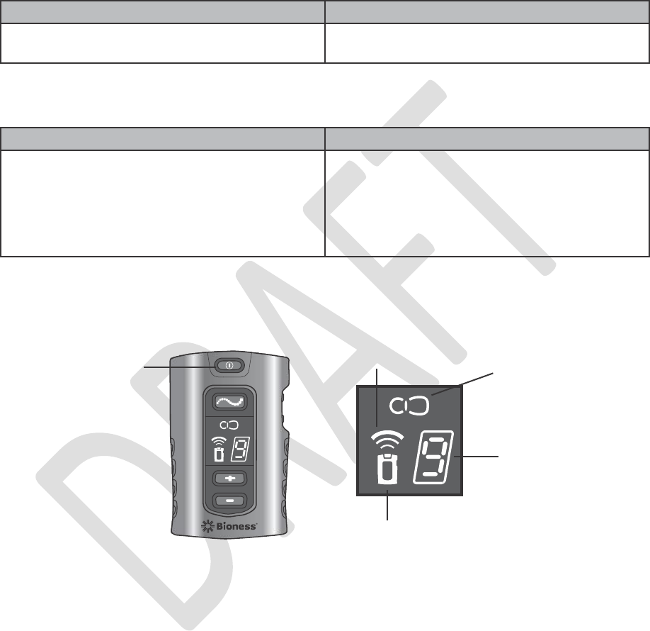
Table 11-3. Troubleshooting, tester.
Table 11-4. Troubleshooting, patient programmer.
Radio Frequency
(RF) Icon
On/Off Button
EPT Icon
Digital Display
Patient Programmer Icon
Figure 11-3. Patient programmer icons and digital display.
Chapter 11 - Troubleshooting
79
Patient Programmer Indicator
Problems/Solutions
Patient Programmer Will Not Turn On
Battery Failure; Charger Failure; Patient
Programmer Failure
• Charge the patient programmer.
• Change the battery in the patient
programmer.
• Contact your local distributor.
Tester
Tester Will Not Buzz
• Check to see if EPT is charged.
• Replace the tester.
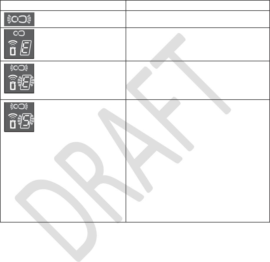
.
cease activity until its working temperature
• Remove the StimRouter electrode from the
• Check to see that the protective covers were
Table 11-5. Troubleshooting, patient programmer, EPT icon.
80
Clinician’s Guide
EPT Icon
Problems/Solutions
EPT Battery Charge Level is Low
• Charge the EPT.
EPT Icon FLASHES
YELLOW
EPT Icon GLOWS RED and
“E” appears in the Digital
Display
EPT Malfunction
• • Contact your local distributor.
EPT Icon FLASHES RED
and “E” FLASHES in the
Digital Display
EPT Temperature Error
• The EPT is either too hot or too cold and will
range is restored. Restore the EPT to its
working temperature range.
EPT Icon FLASHES
RED and Intensity Level
FLASHES in the Digital
Display
Faulty Electrode Contact
• Turn off the patient programmer.
skin.
removed from the StimRouter electrode.
• Check to see that the EPT is correctly
attached to the StimRouter electrode. If
necessary, reattach the EPT into the
StimRouter electrode.
• Make sure that nothing is on the gel electrodes
or on the skin that would interfere with
electrode contact with the skin.
• Re-adhere the StimRouter electrode to the
skin.
• Replace the StimRouter electrode.
• Clean the skin.
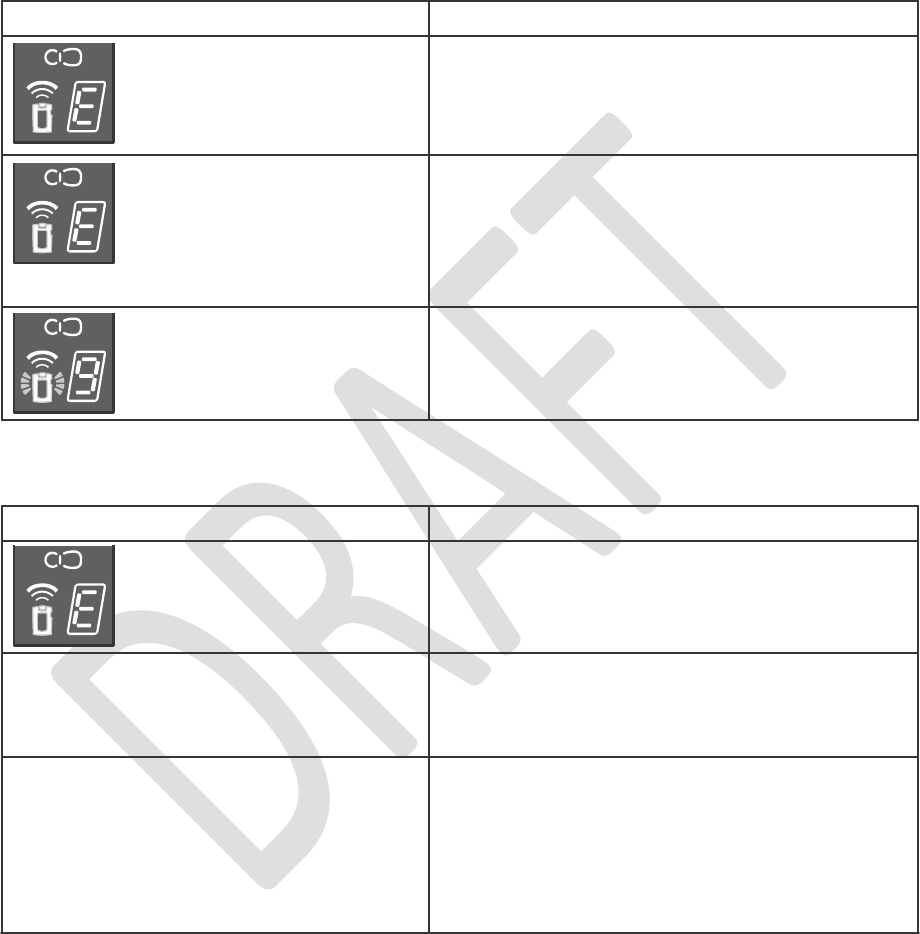
programmer.
on.
Low
Table 11-6. Troubleshooting, patient programmer, patient programmer icon.
the patient programmer.
patient programmer but not touching.
Chapter 11 - Troubleshooting
81
RF Icon
Problems/Solutions
RF Icon GLOWS RED and
“E” Appears in the Digital
Display Immediately After the
Registration Attempt
Registration Failure; Unknown Reason
• Retry the process.
RF Icon GLOWS RED, and “E” and then
“2” Appear in the Digital Display
Immediately After the Registration Attempt
Registration Failure; More than One EPT Found
• Make sure only one EPT is within 10 feet of
• Retry the process.
RF Icon GLOWS RED, and “E” and then
“0” Appear in the Digital Display
Immediately After the Registration Attempt
Registration Failure; No EPT Found
• Make sure the EPT is within inches of the
• Connect the EPT to the charger.
•
• Retry the process.
Patient Programmer Icon
Problems/Solutions
While Charging, Patient
Programmer Icon GLOWS
RED and “E” Appears in the
Digital Display
Charging Error
• Reconnect the charger cable to the patient
• Replace the battery in the patient programmer.
Patient Programmer Icon
GLOWS RED and “E”
Appears in the Digital Display
Patient Programmer Malfunction
• Turn the patient programmer off and then back
• Check to see if one of the buttons is stuck
and, if so, try to release it.
• Contact your local distributor.
Patient Programmer Icon
FLASHES YELLOW
Patient Programmer Battery Charge Level is
• Charge the patient programmer.

Failure
Table 11-7. Troubleshooting, patient programmer, RF icon.
Table 11-8. Troubleshooting, EPT and stimulation.
82
Clinician’s Guide
EPT and Stimulation
Solutions
Stimulation Not As Effective As Usual
• Check the orientation of the StimRouter
electrode, it should be over the receiver end of
the lead.
• Make sure the StimRouter electrode is
securely adhered to the skin.
• Visually inspect the StimRouter electrode to
make sure the gel is aligned with the contour
of the electrode.
• Review the skin care instructions.
• Clean the skin with a damp cloth.
• Change the StimRouter electrode, if the skin
is dry.
• Trim hair from the StimRouter electrode site.
• Test the EPT using the tester.
Undesirable Motor Response
• Decrease the stimulation intensity level.
• Check the placement of the StimRouter
electrode.
EPT Charging Light Does Not Turn On
• Check the connection.
• Check the Y cable (disconnect it and connect
charger directly).
• Check that the charger light turns on.
• Contact your local distributor.
RF Icon
Problems/Solutions
RF Icon FLASHES RED
Radio Communication Failure or EPT Battery
• Make sure the patient programmer and EPT
are within 10 feet of each other.
• If the components are within range, then turn
the patient programmer off and back on.
• Connect the EPT to the charger.• Re-register
the components.
• Contact your local distributor

12
Technical
Specifications
Wireless (RF) Communications Specifications
Chapter 12 - Technical Specifications
83
Capabilities
• Communication between the patient programmer and EPT
• Communication between the Clinician Programmer and Bluetooth-
enabled printer
Functions
RF Communication is used between the EPT and patient programmer,
enabling the Clinician Programmer to perform the following functions:
• Define stimulation parameters and programs (e.g., pulse width, amplitude)
• Control stimulation (e.g., start/stop stimulation, change programs,
adjust stimulation amplitude)
• Display system status (e.g., battery charge level, error codes)
• Retrieve patient stimulation session data
Bluetooth communication is used between the clinician programmer and
the HP printer to print stimulation parameters and use history.
Modes
• Online Clinician Programmer mode (Clinician Programmer connected to
patient programmer and EPT)
Characteristics
EPT and patient programmer
• Frequency band: 2.400 up to 2.4835 GHz
• RF Frequency channels: 29 channels
• Channel spacing: 580.810 kHz
• Antenna type: Integrated chip antenna
• Transceiver duplexing scheme: TDD
• Frequency synthesizer settling time: < 1 msec
• Modulation frequency: 0.5 Mbps
• Modulation type: Minimum Shift Keying (MSK)
• Transmit power (EIRP): EPT, -16 dBm; patient programmer, 4.1 dBm
• Modulation baud rate: 500 kHz
• Modulation bandwidth: 590 kHz
Clinician Programmer
• Bluetooth 2.0

of sight is available, up to 7 m distance between them. The communication
•
Packet error rate of <1%
84
Clinician’s Guide
Locations and
Ranges
The patient programmer and EPT communicate when an object-free line
range will be shortened if conductive objects, such as metal or the human
body, are in the communication path between the patient programmer and
EPT. The patient programmer alerts visually when loss of communication
with the registered EPT occurs. Intermittent RF communication may also
cause some delay in user-controlled operations.
Minimum
Quality of
Service
• Delay in delivery of RF command of <1 second
Bluetooth Specifications
Bluetooth Type
Class 2, Bluetooth v2.0
Frequency
2400 MHz to 2483.5 MHz (2.4 GHz Industrial Scientific Medical Band)
Modulation
Scheme
(automatically
selected)
GFSK, pi/4-DQPSK, 8-DPSK
Maximum Data
Rate
3 Mb/s
Maximum
Power
4 dBm (2.5 mW)
Maximum
Range
10 m
HP PDA iPAQ 210,
Maximum
Power
-3 dBm (0.5 mW)
Encryption
8 to128 bit encryption key
HP bt500 Bluetooth USB 2.0 Wireless Adapter
Maximum
Power
4 dBm (2.5 mW)
Encryption
8 to 128 bit encryption key

Troubleshooting Wireless Technology
The patient programmer will emit audio and visual alerts if RF communication fails. See below.
Report problems your local distributor.
Privacy of StimRouter Wireless Communication
While the frequency band used by the StimRouter wireless system can be used by other users
of the band, the privacy of the StimRouter wireless system is ensured by:
•
•
•
•
•
•
The unique ID of paired components.
Proprietary communication protocol.
Use of randomized frequency channels (frequency hopping).
Use of whitening function (data randomizing).
Bluetooth communication is used exclusively in the clinician’s office.
Bluetooth serves for the communication between the Clinician’s Programmer System
(CPS) and a HP printer using a paired HP bt500 wireless adapter.
There is a risk of an interruption in the wireless
communication
resulting in the StimRouter system
not responding to the user input.
Failure
Chapter 12 - Technical Specifications
85
RF Icon FLASHES RED
Radio Communication Failure or EPT Battery
• Make sure the patient programmer and EPT
are within 10 feet of each other.
• If the components are within range, then turn
the patient programmer off and back on.
• Connect the EPT to the charger.• Re-register
the components. Contact your local distributor.

86
Clinician’s Guide

13
Appendix
-
EMI Tables
Electromagnetic Emissions
The StimRouter system is medical electrical equipment and was tested for electromagnetic
compatibility (EMC) in accordance with International Electrotechnical Committee (IEC) 60601-
1-2. The following tables provide information regarding the EMC testing and guidance for safe
use of the system. The StimRouter system should be configured and used in accordance with
the instructions provided in this manual.
There is potential for interference between electronic devices, including cell phones and other
medical devices
such as a
body-
worn
insulin pump. Stimulation control
may be
delayed. Maintain
a minimum safe separation distance of 15 cm (6 in.) between the StimRouter system and all
other electronic devices. If interference is suspected or anticipated, distance yourself from the
source of interference.
Chapter 13 - Appendix - EMI Tables
87

Guidance and Manufacturer’s Declaration Electromagnetic Emissions
The StimRouter system is intended for use in the electromagnetic environment specified below.
The customer or the user of the StimRouter system should assure that it is used in such an
environment.
very low, about 100 times lower than a commercially
88
Clinician’s Guide
Emissions Test
Compliance
Electromagnetic Environment - Guidance
RF emissions
CISPR 11
Group 1
The StimRouter system uses RF energy for short-
range communications. Therefore, its RF emissions are
available cell phone. Though unlikely, portable and
mobile RF communications equipment, such as the
StimRouter patient programmer, EPT and clinician
programmer, could affect medical electrical equipment.
The RF-enabled components of the StimRouter system
are suitable for use in all establishments, including
domestic establishments and those directly connected
to the public low- voltage power supply network that
supplies buildings used for domestic purposes.
RF emissions
CISPR 11
Class B
Harmonic emissions
IEC 61000-3-2
Class A
Voltage fluctuations/
flicker emissions
IEC 61000-3-3
Complies

Guidance and Manufacturer’s Declaration Electromagnetic Immunity
The StimRouter system is intended for use in the electromagnetic environment specified below.
The user of the StimRouter system should assure that it is used in such an environment.
- Guidance
covered with synthetic material,
least 30%.
hospital environment.
that of a typical commercial or
continues operation during
it is normally powered by each
environment.
NOTE: UT is the a.c.mains voltage prior to application of the test level.
Chapter 13 - Appendix - EMI Tables
89
Immunity Test
IEC 60601 Test
Level
Compliance Level
Electromagnetic Environment
Electrostatic
discharge
(ESD)
IEC 61000-4-2
±6 kV contact
±8 kV air
±6 kV contact
±8 kV air
Floors should be wood, concrete
or ceramic tile. If floors are
the relative humidity should be at
Electrical fast
transient/ burst
IEC 61000-4-4
±2 kV for Power
supply lines
±1 kV for input/
output lines
±2 kV for Power
supply lines
Not applicable. No
input/ output lines.
Mains power quality should be
that of a typical commercial or
hospital environment.
Surge
IEC 61000-4-5
±1 kV line (s) to
line(s)
±2 kV to earth
±1 kV line to line
Not applicable.
No grounded
interconnections.
Mains power quality should be
that of a typical commercial or
Voltage dips,
short
interruptions
and voltage
variations on
power supply
input lines
IEC 61000-4-11
<5% UT
(>95% dip in UT)
for 0.5 cycle
40% UT
(60% dip in UT)
for 5 cycles
70% UT
(30% dip UT) for
25 cycles
<5% UT
(>95% dip in UT)
for 5 sec
<5% UT
(>95% dip in UT) for
0.5 cycle
40% UT
(60% dip in UT) for
5 cycles
70% UT
(30% dip UT) for 25
cycles
<5% UT
(>95% dip in UT) for
5 sec
Mains power quality should be
hospital environment.
The StimRouter system
power mains interruptions, as
component battery.
Power frequency
(50/ 60 Hz)
magnetic field
IEC 61000-4-8
3 A/m
3 A/m
Power frequency magnetic fields
should be at levels characteristic
of a typical location in a
typical commercial or hospital

Guidance and Manufacturer’s Declaration Electromagnetic Immunity
The StimRouter system is intended for use in the electromagnetic environment specified below.
The customer or the user of the StimRouter system should assure that it is used in such an
environment.
Environment - Guidance
d = 1.2√P
800 Mhz
2.5 GHz
NOTE 1: At 80 MHz and 800 MHz, the higher frequency range applies.
NOTE 2:
These guidelines
may not
apply
in all
situations. Electromagnetic propagation
is affected
by absorption and reflection from structures, objects and people.
90
Clinician’s Guide
Immunity Test
IEC 60601 Test
Level
Compliance
Level
Electromagnetic
Conducted RF
IEC 61000-4-6
Radiated RF
IEC 61000-4-3
3 Vrms
150 kHz to 80
MHz
3 V/m
80 Mhz to 2.5
GHz
3 Vrms
150 kHz to 80
MHz
10 V/m
26 MHz to 1 GHz
3 V/m
1 GHz to 2.5 GHz
Portable and mobile RF
communications equipment
should be used no closer to
any part of the StimRouter
system, including cables, than
the recommended separation
distance calculated from the
equation applicable to the
frequency of the transmitter.
Recommended separation
distance (d)
d = 0.4√P 80 MHz to
d = 2.3√P 800 MHz to
Where P is the maximum
output power rating of the
transmitter in watts (W)
according to the transmitter
manufacturer and d is the
recommended separation
distance in meters (m).
Field strengths from fixed RF
transmitters, as determined
by an electromagnetic site
survey,a should be less than
the compliance level in each
frequency range.b Interference
may occur in the vicinity of
equipment marked with
the following symbol:
Guidance and Manufacturer’s Declaration Electromagnetic Immunity
a
Field strengths from fixed transmitters, such as base stations for radio (cellular/cordless)
telephones
and land mobile radios, amateur radio, AM and FM radio broadcast and TV broadcast cannot
be predicted theoretically with accuracy. To assess the electromagnetic environment due to
fixed RF transmitters, an electromagnetic site survey should be considered. If the measured
field strength in the location in which the StimRouter system is used exceeds the applicable RF
compliance level above, the StimRouter system should be observed to verify normal operation. If
abnormal performance is observed, additional measures may be necessary, such as reorienting
or relocating the StimRouter system.
b Over the frequency range 150 kHz to 80 MHz, field strengths should be less than 3 V/m.
Recommended Separation Distances Between Portable and Mobile RF
Communications Equipment and the StimRouter System
The StimRouter system is intended for use in an electromagnetic environment in which radiated
RF disturbances are controlled. The customer or the user of the StimRouter system can help
prevent electromagnetic interference by maintaining a minimum distance between portable and
mobile
RF
communications equipment (transmitters)
and the
StimRouter system
as recommended
below, according to the maximum output power of the communications equipment.
d = 1.2√P
d = 0.4√P
d = 2.3√P
For transmitters rated at a maximum output power not listed above, the
recommended
separation
distance d in meters (m) can be estimated using the equation applicable to the frequency of the
transmitter, where P is the maximum output power rating of the transmitter in watts (W) according
to the transmitter manufacturer.
NOTE
1:
At 80 MHz and 800 MHz, the
separation distance
for the
higher frequency range
applies.
NOTE 2:
These guidelines
may not
apply
in all
situations. Electromagnetic propagation
is affected
by absorption and reflection from structures, objects and people.
Chapter 13 - Appendix - EMI Tables
91
Rated Maximum
Output Power of
Transmitter
W
Separation Distance According to Frequency of Transmitter
150 kHz to 80 MHz 80 MHz to 800 MHz 800 MHz to 2.5 GHz
0.01
4.7 in. (0.12 m)
1.6 in (0.04 m)
9.1 in. (0.23 m)
0.1
15 in. (0.38 m)
4.7 in. (0.12 m)
2 ft 5 in. (0.73 m)
1
3 ft 11 in. (1.2 m)
15.7 in. (0.4 m)
7 ft 7 in. (2.3 m)
10
12 ft 6 in. (3.8 m)
4 ft 2 in. (1.26 m)
24 ft 11 in. (7.3 m)
100
39 ft 4 in. (12 m)
13 ft 1 in. (4 m)
75 ft 6 in. (23 m)

92
Clinician’s Guide
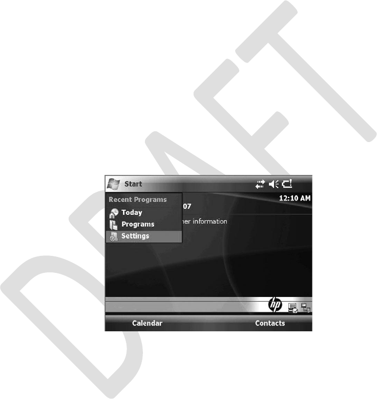
14
Bluetooth Printer Set-Up
The StimRouter clinician programmer and a Bluetooth printer are Bluetooth-enabled devices.
To communicate, the clinician programmer and the printer must be within 30 feet of each other
and turned on.
Enabling Bluetooth
To set up a Bluetooth printer:
1.
Turn the clinician programmer on, press “Start” and then “Settings.” See Figure 14-1.
Figure 14-1. Press “Start” and then “Settings.”
Chapter 14 - Bluetooth Printer Set-up
93
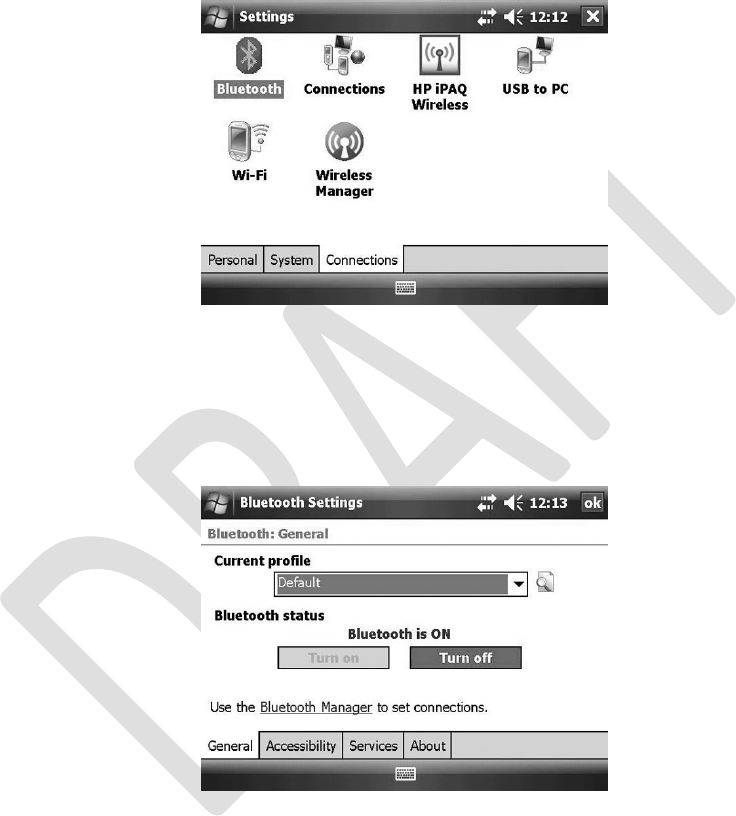
2.
The Settings screen will open. Press the CONNECTIONS TAB and then the Bluetooth
icon. See Figure 14-2.
Figure 14-2. Press the Bluetooth icon.
3.
From the GENERAL TAB, press “Turn on” (under “Bluetooth status”) and then the
“Bluetooth Manager” hyperlink. See Figure 14-3.
Figure 14-3. Press “Turn on.”
4.
The Bluetooth Manager screen will open. Press “New.” See Figure 14-4.
94
Clinician’s Guide
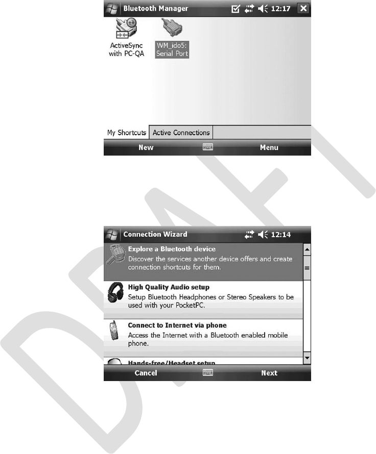
Figure 14-4. Press “New.” (Your screen icons may vary.)
5.
The Connection Wizard will open. Press “Explore a Bluetooth device.” See Figure 14-5.
Figure 14-5. Press “Explore a Bluetooth device.”
Chapter 14 - Bluetooth Printer Set-up
95
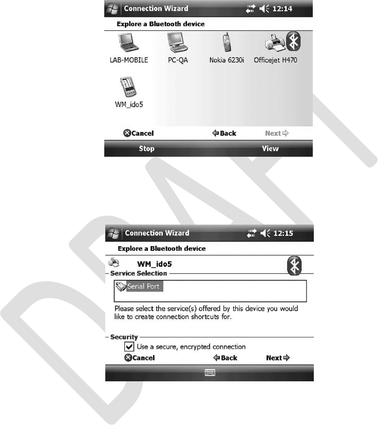
6.
Wait for the application to process, press “Officejet H470” and then “Next.” See
Figure 14-6.
Figure 14-6. Press “Next.”
7.
Press “Serial Port” under “Service Selection” and then “Next.” See Figure 14-7.
Figure 14-7. Press “Serial Port” and then “Next.”
96
Clinician’s Guide
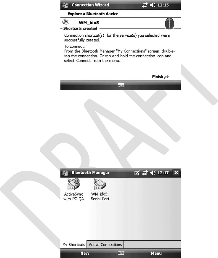
8.
Press “Finish.” See Figure 14-8.
Figure 14-8. Press “Finish.”
Device Pairing
To pair the clinician programmer with a Bluetooth printer:
1.
Return to the Bluetooth manager screen, and then press “Menu.” See Figure 14-9.
Figure 14-9. Press “Menu.” (Your screen icons may vary.)
Chapter 14 - Bluetooth Printer Set-up
97
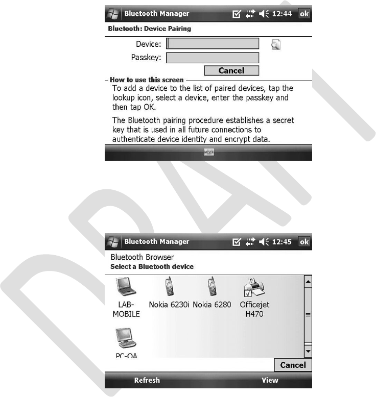
2.
3.
From the pop-up menu, press “Paired Devices” and then “Add.”
Under “Bluetooth: Device Pairing” press the lookup icon (right of the “Device” field). See
Figure 14-10.
Figure 14-10. Press the lookup icon.
4.
From the Bluetooth Browser, select “Officejet H470” and press “View.” See Figure 14-11.
Figure 14-11. Select the Officejet H470 icon and then “View.”
98
Clinician’s Guide
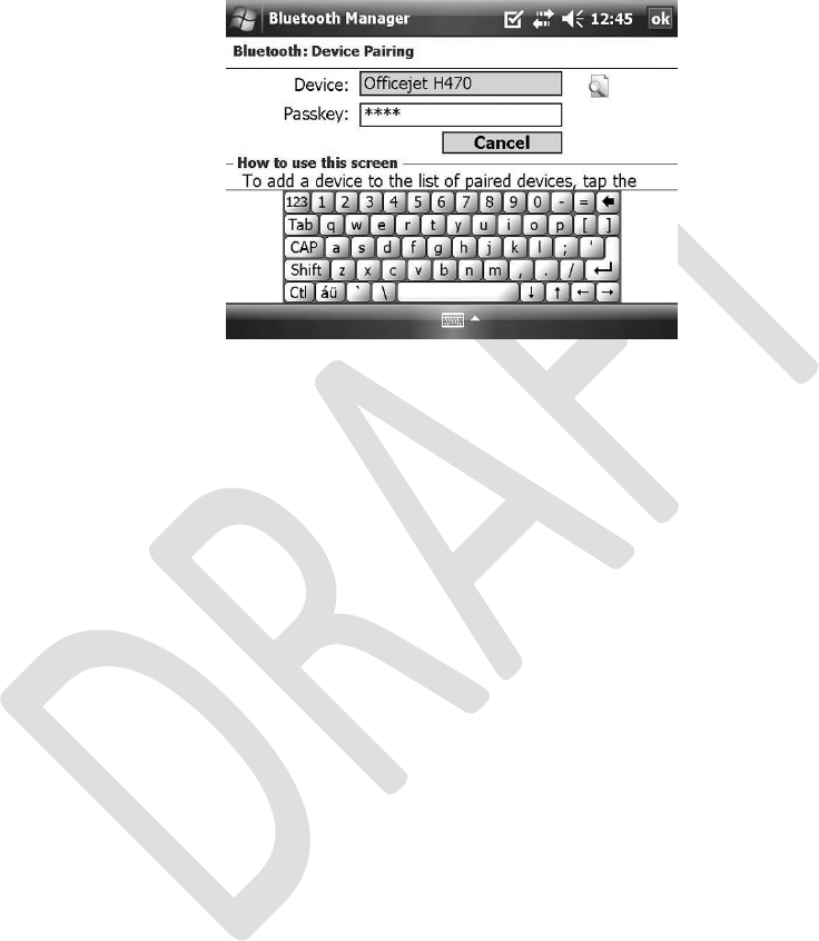
5.
Enter “0000” in the “Passkey” field and press “ok.” See Figure 14-12.
Figure 14-12. Enter “0000” in the “Passkey” field. Press “ok.”
Chapter 14 - Bluetooth Printer Set-up
99