Bioscrypt 4GFLEXH Fingerprint Access Control Accessory: V-Flex 4G User Manual
Bioscrypt, Inc. Fingerprint Access Control Accessory: V-Flex 4G
User Manual
Installation Guide
Bioscrypt® V-Station™ 4G
Bioscrypt® V-Flex™ 4G
Document Version 1.0

Copyright Information
Part No. 430-4G-200-00-000
© 2009, L-1 Identity Solutions Inc. ii
© 2009, L-1 Identity Solutions, Inc.
All rights reserved. This product and related documentation are protected by copyright and distributed
under licenses restricting their use, copying, distribution, and de-compilation. No part of this product or
related documentation may be reproduced in any form by any means without written permission from
L-1 Identity Solutions and its licensors, if any.
Redistributions of source code must retain the above copyright notice, this list of conditions and the fol-
lowing disclaimer. Redistributions in binary form must reproduce the above copyright notice, this list of
conditions and the following disclaimer in the documentation and/or other materials provided with the
distribution.
Neither the name of the BioAPI® Consortium nor the names of its contributors may be used to endorse
or promote products derived from this software without specific prior written permission.
TRADEMARKS
The trademarks identified herein are the trademarks or registered trademarks of L-1 Identity Solutions,
Inc. All other brands and products referenced herein are acknowledged to be trademarks or registered
trademarks of their respective holders or manufacturers.
THE PRODUCT AND PUBLICATION ARE PROVIDED “AS IS” WITHOUT WARRANTY OF ANY KIND,
EITHER EXPRESS OR IMPLIED, INCLUDING, BUT NOT LIMITED TO, THE IMPLIED WARRANTIES
OF MERCHANTABILITY, FITNESS FOR A PARTICULAR PURPOSE, OR NON-INFRINGEMENT.
THIS PUBLICATION COULD INCLUDE TECHNICAL INACCURACIES OR TYPOGRAPHICAL ER-
RORS. CHANGES ARE PERIODICALLY ADDED TO THE INFORMATION HEREIN; THESE
CHANGES WILL BE INCORPORATED IN NEW EDITIONS OF THE PUBLICATION. L-1 IDENTITY SO-
LUTIONS, INC MAY MAKE IMPROVEMENTS AND/OR CHANGES IN THE PRODUCT(S) AND/OR
THE PROGRAM(S) DESCRIBED IN THIS PUBLICATION AT ANY TIME.
IMPORTANT—Please refer to the L-1 Identity Solutions End User License Agreement document and
read it carefully before using any L-1 Identity Solutions software on your computer. This document con-
tains important information about your legal rights.
COPYRIGHT INFORMATION

Notices
Part No. 430-4G-200-00-000
© 2009, L-1 Identity Solutions Inc. A-1
Notices
The Veri-Series 4G line of products have been tested for compliance with all applicable
international standards. The resulting approvals are listed below, and are additionally printed on
the labelling located on the rear panel of the product.
V- Flex 4G FCC, CE
V- Station 4G FCC, CE
FCC Information to Users
This device complies with part 15 of the FCC Rules. Operation is subject to the following two
conditions: (1) This device may not cause harmful interference, and (2) this device must accept
any interference received, including interference that may cause undesired operation.
NOTE: This equipment has been tested and found to comply with the limits for a Class B digital
device, pursuant to part 15 of the FCC Rules. These limits are designed to provide
reasonable protection against harmful interference in a residential installation. This
equipment generates, uses and can radiate radio frequency energy and, if not installed
and used in accordance with the instructions, may cause harmful interference to radio
communications. However, there is no guarantee that interference will not occur in a
particular installation. If this equipment does cause harmful interference to radio or
television reception, which can be determined by turning the equipment off and on, the
user is encouraged to try to correct the interference by one or more of the following
measures:
—Reorient or relocate the receiving antenna.
—Increase the separation between the equipment and receiver.
—Connect the equipment into an outlet on a circuit different from that to which the receiver is
connected.
—Consult the dealer or an experienced radio/TV technician for help.
This Class B digital apparatus complies with Canadian ICES-003.
Applicable only to V-Station 4G series product: This product complies with FCC radiation
exposure limits set forth for an uncontrolled environment. To comply with FCC RF exposure
requirements, it must be installed and operated in accordance with provided instructions. The unit
requires minimum 20cm (8inch) spacing between the unit and all person’s body (excluding hands
and feet) during wireless modes of operation.
CE Information to Users
All Veri-Series 4G devices have the CE mark, for compliance with CISPR22/EN55022
requirements. For European Union (EU) countries, V-Flex 4G and V- Station 4G are compliant
with CE under the R&TTE Directive, related to the radio transceivers that are part of their design.
Warning to Users
Caution: Changes or modifications not expressly approved by Bioscrypt Inc. could void the user’s
authority to operate the equipment.

Table of Contents
Part No. 430-4G-200-00-000
© 2009, L-1 Identity Solutions Inc.
Table of Contents
1. Introduction ........................................................................................................................................ 1-2
1.1. Symbols Used in this Guide ............................................................................................... 1-2
1.2. Product Overview ............................................................................................................... 1-3
1.2.1. V-Station 4G ...................................................................................................... 1-3
1.2.2. V-Flex 4G ........................................................................................................... 1-4
1.3. Sensors .............................................................................................................................. 1-5
1.3.1. UPEK TCS1 ....................................................................................................... 1-5
1.3.2. UPEK TCS2 ....................................................................................................... 1-5
1.3.3. Secugen Optical ................................................................................................. 1-5
1.4. Device Dimensions ............................................................................................................ 1-6
1.4.1. V-Station 4G ...................................................................................................... 1-6
1.4.2. V-Flex 4G ........................................................................................................... 1-7
1.5. Safety Precautions ............................................................................................................. 1-8
1.5.1. Grounding .......................................................................................................... 1-8
1.5.2. Electro-Static Discharge .................................................................................... 1-8
1.5.3. Device Handling Guidelines ............................................................................... 1-8
2. Planning the Installation ..................................................................................................................... 2-2
2.1. Recommended Steps for a Successful Installation ........................................................... 2-3
2.2. Requirements ..................................................................................................................... 2-4
2.2.1. Hardware Requirements .................................................................................... 2-4
2.2.2. Computer Requirements .................................................................................... 2-4
2.2.2.1. SecureAdmin Server Requirements .................................................... 2-4
2.2.2.2. SecureAdmin Client Requirements ..................................................... 2-4
2.2.2.3. Microsoft .Net 3.5 Requirements ......................................................... 2-4
2.2.2.4. Supported Operating Systems ............................................................ 2-5
2.2.2.5. SQL Server 2005 Express Edition........................................................ 2-5
2.2.2.6. Oracle 10G Express ............................................................................ 2-5
2.2.3. Network Requirements ...................................................................................... 2-5
2.2.4. Software Requirements ..................................................................................... 2-5
2.3. Unpack Equipment ............................................................................................................. 2-6
2.3.1. Parts List ............................................................................................................ 2-6
2.4. Choosing the Install Location ............................................................................................. 2-7
2.5. Plan Device Network .......................................................................................................... 2-8
2.6. Choose Network Type ....................................................................................................... 2-9
2.6.1. RS-232 ............................................................................................................... 2-9
2.6.2. RS-485 ............................................................................................................... 2-9
iii

Table of Contents
Part No. 430-4G-200-00-000
© 2009, L-1 Identity Solutions Inc.
2.6.2.1. RS-485 Cable Specification ............................................................. 2-10
2.6.2.2. RS-485 Cable Lengths ..................................................................... 2-10
2.6.2.3. RS-485 Network Topology ............................................................... 2-10
2.6.3. Ethernet ........................................................................................................... 2-11
2.6.4. Wireless Network Design Considerations ....................................................... 2-11
2.7. Choose Power Source .................................................................................................... 2-12
3. Install Software ................................................................................................................................... 3-2
3.1. SecureAdmin Server .......................................................................................................... 3-2
3.1.1. Repairing an Installation of SecureAdmin Server .............................................. 3-7
3.1.2. Uninstalling SecureAdmin Server ...................................................................... 3-7
3.1.3. Upgrading an Installation of SecureAdmin Server ............................................. 3-7
3.2. SecureAdmin Client ........................................................................................................... 3-8
3.2.1. Modifying an Installation of SecureAdmin Client ............................................ 3-12
3.2.2. Repairing an Installation of SecureAdmin Client ............................................ 3-12
3.2.3. Uninstalling SecureAdmin Client .................................................................... 3-12
3.2.4. Upgrading an Installation of SecureAdmin Client ........................................... 3-13
4. Install Hardware ................................................................................................................................. 4-2
4.1. Wall Mounting Schemes .................................................................................................... 4-2
4.2. Installing a Mounting Plate ................................................................................................. 4-2
4.3. Installation Hardware ......................................................................................................... 4-5
4.4. Attach Device to Mounting Plate ........................................................................................ 4-5
4.5. Connect Device to Earth Ground ....................................................................................... 4-6
4.6. Connect Device to Power Source ...................................................................................... 4-7
4.7. Connect Device to Network ............................................................................................... 4-9
4.7.1. Ethernet Network Connections .......................................................................... 4-9
4.7.2. RS-232/RS-485 Network Connections .............................................................. 4-9
4.7.3. Wireless Network Connections ....................................................................... 4-11
4.8. Connect Device to Door .................................................................................................. 4-12
4.9. Aux Port .......................................................................................................................... 4-14
4.10. Install Ferrite Core ........................................................................................................ 4-15
5. System Start-up Procedures .............................................................................................................. 5-2
5.1. System Start-up Overview ................................................................................................. 5-2
5.2. Device Configuration Check .............................................................................................. 5-2
5.3. RS-232 to RS-485 Converter Ground Fault Check ........................................................... 5-3
5.4. Device Ground Fault Check................................................................................................ 5-3
6. Configure Device................................................................................................................................. 6-2
6.1. Register Device................................................................................................................... 6-2
iv

Table of Contents
Part No. 430-4G-200-00-000
© 2009, L-1 Identity Solutions Inc.
7. Maintenance and Cleaning ................................................................................................................. 7-2
7.1. Field Maintenance............................................................................................................... 7-2
7.1.1. Disarming the Tamper Protection ...................................................................... 7-2
7.1.2. Replacing the Sensor ......................................................................................... 7-3
7.1.2.1. V-Flex 4G ............................................................................................ 7-3
7.1.2.2. V-Station 4G ........................................................................................ 7-5
7.1.3. Calibrating the Sensor ....................................................................................... 7-7
7.2. Cleaning ............................................................................................................................. 7-9
8. Troubleshooting .................................................................................................................................. 8-2
8.1. Installation Error Messages ................................................................................................ 8-2
8.1.1. Error 1303 - Insufficient Privileges ..................................................................... 8-2
8.1.2. Error 27552 - Error Creating Database .............................................................. 8-3
8.1.3. Invalid Password ................................................................................................ 8-4
8.1.4. Error 27502 - User Not Associated with Trusted SQL Server ........................... 8-5
8.1.5. Error 27502 - SQL Server Does Not Exist ......................................................... 8-6
8.1.6. Insufficient System Memory ............................................................................... 8-7
8.1.7. Out of Disk Space .............................................................................................. 8-8
9. Company Contacts.............................................................................................................................. 9-1
9.1. Registering your Product .................................................................................................... 9-1
v

Table of Contents
Part No. 430-4G-200-00-000
© 2009, L-1 Identity Solutions Inc. vi
This page left blank intentionally

List of Tables
Part No. 430-4G-200-00-000
© 2009, L-1 Identity Solutions Inc. ix
List of Tables
Table 2-1: Communications Network Comparison ................................................................................ 2-9
Table 2-2: Category 5 Cable Characteristics ...................................................................................... 2-10
Table 2-3: V-Station 4G and V-Flex 4G Power Requirements ........................................................... 2-12
Table 4-1: PoE Pin Assignments ........................................................................................................... 4-9

List of Tables
Part No. 430-4G-200-00-000
© 2009, L-1 Identity Solutions Inc. x
This page left blank intentionally

List of Acronyms
Part No. 430-4G-200-00-000
© 2009, L-1 Identity Solutions Inc. xi
List of Acronyms
These acronyms and abbreviations are used in this document:
A Ampere
ABS Acrylonitrile Butadiene Styrene
AC Alternating Current
AUX Auxiliary
AWG American Wire Gauge
CAT-5 Category 5
CD Compact Disc
CISPR Comité Internationale Spécial des Perturbations Radioelectrotechnique
COM Common
DC Direct Current
DPI Dots per Inch
ESD Electro-Static Discharge
FCC Federal Communications Commission
FPF Finger Placement Feedback
GB Gigabyte
GND Ground
Hz Hertz
I/O Input/Output
ID Inner Diameter
kV Kilovolt
LCD Liquid Crystal Display
LED Light Emitting Diode
MAC Media Access Control
mA Milliamp
MB Megabyte
N.C. Normally Closed
N.O. Normally Open
NEG Negative
OD Outer Diameter
PC Personal Computer
PDF Portable Document Format
pF Picofarad
POS Positive
PoE Power Over Ethernet
QVGA Quarter Video Graphics Array
RAM Random Access Memory
RoHS Restriction of Hazardous Substances
TFT Thin Film Transistor
UPS Uninterruptible Power Supply
USB Universal Serial Bus
VAC Volts Alternating Current
VDC Volts Direct Current
W Watt

List of Acronyms
Part No. 430-4G-200-00-000
© 2009, L-1 Identity Solutions Inc. xii
This page left blank intentionally

Glossary
Part No. 430-4G-200-00-000
© 2009, L-1 Identity Solutions Inc. xiii
Glossary
Administrator - A user who is authorized to manage the settings and user information of a fingerprint
reader. Administrators can enroll or delete users and change device settings.
Single Door Access Control - The capability of controlling/monitoring all functions related to a single
entry/exit point.

Glossary
Part No. 430-4G-200-00-000
© 2009, L-1 Identity Solutions Inc. xiv
This page left blank intentionally

Introduction
Part No. 430-4G-200-00-000
© 2009, L-1 Identity Solutions Inc. 1-1
This chapter provides an introduction to the V-Station 4G and V-Flex 4G devices, their specifications
and features, and safety guidelines that should be observed when using or handling the devices.
Chapter Index
1. Introduction ........................................................................................................................................ 1-2
1.1. Symbols Used in this Guide ............................................................................................... 1-2
1.2. Product Overview ............................................................................................................... 1-3
1.2.1. V-Station 4G ...................................................................................................... 1-3
1.2.2. V-Flex 4G ........................................................................................................... 1-4
1.3. Sensors .............................................................................................................................. 1-5
1.3.1. UPEK TCS1 ....................................................................................................... 1-5
1.3.1. UPEK TCS2 ....................................................................................................... 1-5
1.3.1. Secugen Optical ................................................................................................. 1-5
1.4. Device Dimensions ............................................................................................................ 1-6
1.4.1. V-Station 4G ...................................................................................................... 1-6
1.4.2. V-Flex 4G ........................................................................................................... 1-7
1.5. Safety Precautions ............................................................................................................. 1-8
1.5.1. Grounding .......................................................................................................... 1-8
1.5.2. Electro-Static Discharge .................................................................................... 1-8
1.5.3. Device Handling Guidelines ............................................................................... 1-8
CHAPTER 1 - INTRODUCTION
Chapter Overview
Introduction
Part No. 430-4G-200-00-000
© 2009, L-1 Identity Solutions Inc. 1-2
1. INTRODUCTION
This manual provides step-by-step procedures for installing a Bioscrypt V-Station 4G or V-Flex 4G de-
vice. It covers the entire process of physically installing the device, making the necessary power,
ground, and network connections, and registering the device in SecureAdmin. Instructions for field re-
pairs and cleaning are also provided.
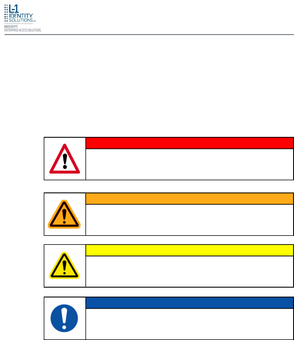
The symbols shown below are used throughout this manual. They denote special issues the
user might encounter. Their definitions are given below.
This symbol denotes a situation needing additional advice to avoid incorrect
usage.
NOTICE
This symbol denotes a warning condition that may cause severe injury or
major damage to property.
WARNING
This symbol denotes a cautionary condition that may cause injury or minor
damage to property.
CAUTION
This symbol denotes a danger condition that may cause death or excessive
damage to property.
DANGER
1.1. SYMBOLS USED IN THIS GUIDE
Introduction
Part No. 430-4G-200-00-000
© 2009, L-1 Identity Solutions Inc. 1-3
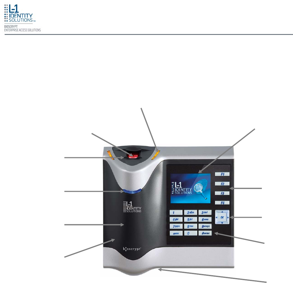
Figure 1-1: V-Station 4G Device
1.2. PRODUCT OVERVIEW
1.2.1. V-STATION 4G
Finger Scan
Sensor
Tricolor Pass/Fail Indicator LEDs
(Amber/Off/Green/Red)
Ridge-Lock™
2.5” backlit TFT LCD
(QVGA, 16 million color)
Illuminated
Keypad
Housing
USB Port
Optional Internal
Smart Card or
Proximity Reader
Power Indicator
LED
Navigation
Keypad
Function
Keys
Introduction
Part No. 430-4G-200-00-000
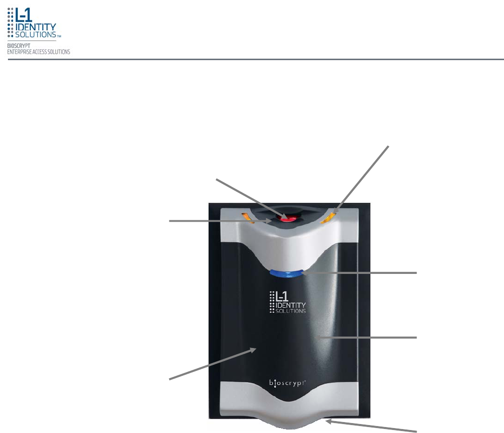
© 2009, L-1 Identity Solutions Inc. 1-4
Figure 1-2: V-Flex 4G Device
1.2.2. V-FLEX 4G
Finger Scan
Sensor
Tricolor Pass/Fail Indicator LEDs
(Amber/Off/Green/Red)
Ridge-Lock™
Housing
Optional Internal
Smart Card or
Proximity Reader
Power Indicator
LED
USB Port
Introduction
Part No. 430-4G-200-00-000
© 2009, L-1 Identity Solutions Inc. 1-5
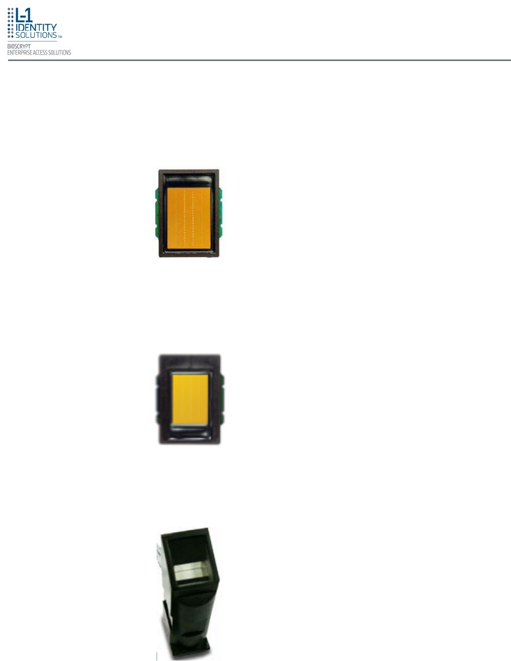
The V-Station 4G and V-Flex 4G devices offer three types of sensor interfaces.
Key Features:
• Active Capacitive Fingerprint sensing
• 256 x 360 Sensor Array 508 DPI
• +/- 15kV Air ESD Resistance
Key Features:
• Active Capacitive Fingerprint sensing
• 208 x 288 Sensor Array 508 DPI
• +/- 15kV Air ESD Resistance
Key Features:
• Optical Fingerprint sensing
• 258 x 336 Sensor Array 500 DPI
• +/- 15kV Air ESD Resistance
1.3. SENSORS
1.3.1. UPEK TCS1
1.3.1. UPEK TCS2
1.3.1. SECUGEN OPTICAL
Figure 1-3: UPEK TCS1 Sensor
Figure 1-4: UPEK TCS2 Sensor
Figure 1-5: Secugen Optical Sensor
Introduction
Part No. 430-4G-200-00-000
© 2009, L-1 Identity Solutions Inc. 1-6
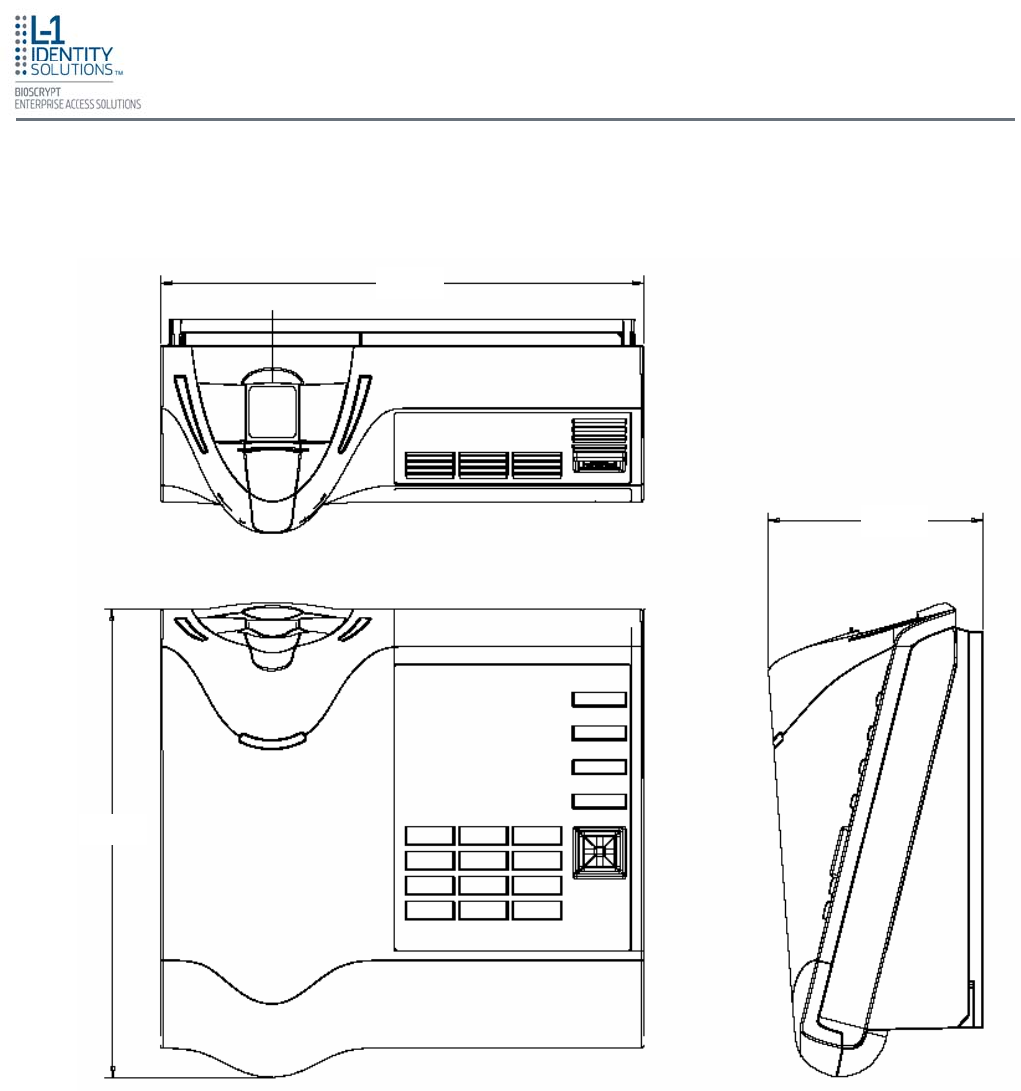
All dimensions in millimeters (mm).
1.4.1. V-STATION 4G
1.4. DEVICE DIMENSIONS
Figure 1-6: V-Station 4G Dimensions
164.58
73.04
159.38
Introduction
Part No. 430-4G-200-00-000
© 2009, L-1 Identity Solutions Inc. 1-7
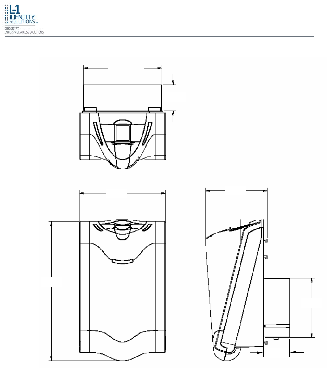
All dimensions in millimeters (mm).
1.4.2. V-FLEX 4G
Figure 1-7: V-Flex 4G Dimensions
89.14
98.00
158.67
67.50
70.53
30.00
30.00

Introduction
Part No. 430-4G-200-00-000
© 2009, L-1 Identity Solutions Inc. 1-8
Below are safety precautions that should be observed when operating or installing a device.
The device's ground connection must be properly connected to avoid damage by
Electro-Static Discharge (ESD). The effects of ESD can degrade or destroy
semiconductor junctions of an electronic device. Earth Ground (EGND) is a low-
impedance path to earth for the purpose of discharging lightning, static, and radiated
energy, and for maintaining the main service entrance at earth potential. Consult your
local electrical codes for guidelines.
Bioscrypt recommends that Administrators inform Users of these points during the
enrollment process:
• Always use the Ridge-Lock to position a finger before touching the sensor.
• Always stand on the ESD-dissipative floor covering (if installed).
• Do not touch other people or objects when touching the sensor.
• Always maintain at least 12 inches of space around yourself when touching the
sensor.
• Do not allow articles of clothing to touch the sensor.
Bioscrypt recommends that Installers always follow these points (in addition to the
points listed above):
• When installing or working on a unit, always use a grounding wrist-strap that is
connected to a quality Earth ground.
• Check the device's cabling for ground faults.
• Ensure that the device's ground connection (located on the rear of the device) is
connected to a quality Earth Ground.
Do not install the device in locations where the device would be exposed to direct
sunlight, high levels of relative humidity, particulate matter, or flammable vapors.
Do not install the device near radiators or other heat sources.
Do not allow magnetic objects to come within close proximity to the device. Strong
magnetic fields might damage the device.
Do not let liquids contact the device.
Do not attempt to alter the device for any reason. Modifications will void the product
guarantee.
Do not attempt to disassemble the device in any way beyond what is necessary for
sensor field replacement.
Do not use the device for any purpose other than for what it was designed.
1.5.2. ELECTRO-STATIC DISCHARGE
1.5.1. GROUNDING
1.5.3. DEVICE HANDLING GUIDELINES
1.5. SAFETY PRECAUTIONS

Introduction
Part No. 430-4G-200-00-000
© 2009, L-1 Identity Solutions Inc. 1-9
Do not plug any equipment into the USB port other than flash memory devices.
Do not allow users to place or hang objects on the device, such as coffee cups or
purses.
Do clean the device regularly to remove dust, grime, and fingerprint residue.
Do instruct users how to present a fingerprint correctly.

Introduction
Part No. 430-4G-200-00-000
© 2009, L-1 Identity Solutions Inc. 1-10
This page left blank intentionally

Planning the Installation
Part No. 430-4G-200-00-000
© 2009, L-1 Identity Solutions Inc. 2-1
Chapter 2 - Planning the Installation
This chapter details how to plan a successful installation, recommended steps, and explains the
hardware and software components of typical setup scenarios.
Chapter Index
2. Planning the Installation ..................................................................................................................... 2-2
2.1. Recommended Steps for a Successful Installation ........................................................... 2-3
2.2. Requirements ..................................................................................................................... 2-4
2.2.1. Hardware Requirements .................................................................................... 2-4
2.2.2. Computer Requirements .................................................................................... 2-4
2.2.2.1. SecureAdmin Server Requirements .................................................... 2-4
2.2.2.2. SecureAdmin Client Requirements ..................................................... 2-4
2.2.2.3. Microsoft .Net 3.5 Requirements ......................................................... 2-4
2.2.2.4. Supported Operating Systems ............................................................ 2-5
2.2.2.5. SQL Server 2005 Express Edition........................................................ 2-5
2.2.2.6. Oracle 10G Express ............................................................................ 2-5
2.2.3. Network Requirements ...................................................................................... 2-5
2.2.4. Software Requirements ..................................................................................... 2-5
2.3. Unpack Equipment ............................................................................................................. 2-6
2.3.1. Parts List ............................................................................................................ 2-6
2.4. Choosing the Install Location ............................................................................................. 2-7
2.5. Plan Device Network .......................................................................................................... 2-8
2.6. Choose Network Type ....................................................................................................... 2-9
2.6.1. RS-232 ............................................................................................................... 2-9
2.6.2. RS-485 ............................................................................................................... 2-9
2.6.2.1. RS-485 Cable Specification ............................................................. 2-10
2.6.2.2. RS-485 Cable Lengths ..................................................................... 2-10
2.6.2.3. RS-485 Network Topology ............................................................... 2-10
2.6.3. Ethernet ........................................................................................................... 2-11
2.6.4. Wireless Network Design Considerations ....................................................... 2-11
2.7. Choose Power Source .................................................................................................... 2-12
Chapter Overview
Planning the Installation
Part No. 430-4G-200-00-000
© 2009, L-1 Identity Solutions Inc. 2-2
2. PLANNING THE INSTALLATION
Planning the installation is the single most important aspect of a successful installation. In general, you
need to consider the access controller, the door locks, the devices, and the need for a network. By the
time you are ready to install the system, all of the details presented in the list below should be known.
Take a moment to go through them now before starting your installation.
During the planning phase, you should determine:
• What type of authentication is required for your application?
• How many doors need to be secured?
• What type of device will be on each door? Doors already inside a secure area might not need the
same type or level of security.
• If multiple V-Series 4G devices require networking for template distribution/management, then a
dedicated PC is recommended to administer the system, as well as an RS-485 to RS-232
converter, and cabling for serial communications or cabling for Ethernet.
• Verify that the chosen access controller supports the Wiegand formats supported by V-Station 4G
devices.
• Identify all wiring by the signal levels it is to carry. Use separate cables and conduits for
different signal groups to avoid cross talk. Plan to separate them by these groups:
Power distribution: Wires carry power to devices, door strikes, etc.
Data communication: RS-485, RS-232, USB, Wiegand, Ethernet, etc.
Signal: Door contact, request-to-exit push button, alarm input, etc.
• When planning device placement, determine the distance limitation of each signal type and use
repeaters if necessary.
• Determine the availability of a quality earth ground
• V-Series 4G devices are intended for indoor use only.
If you have any unresolved issues with the items on this list, contact L-1 EAS Technical Support
for additional information before beginning any installation.
V-Station 4G and V-Flex 4G devices should be installed by only a qualified
technician. If you are not qualified to perform an installation task, call L-1
EAS Technical Support or contact a qualified installer.
WARNING

Planning the Installation
Part No. 430-4G-200-00-000
© 2009, L-1 Identity Solutions Inc. 2-3
Every installation is unique. Sometimes the issues are well defined and can be handled in a
standard fashion; sometimes the issues are very specific and may not be immediately recogniz-
able.
L-1 EAS recommends following these steps for a successful installation:
Plan the installation - Choose the type of hardware required, decide if a network is required, and
decide on the location and number of required devices.
Unpack all items - Unpack all items and check against the packing list.
Install network hardware components - Install the cabling and components needed to run the
system.
Install software - Install the software needed to set up the devices.
Preconfigure device - Connect the device to the USB cable, supply power to the device, and
preconfigure the device.
Mount devices - Mount the devices in their final locations
Power distribution and device hook up - Connect the device wiring via the back panel.
Power-up procedure - Check the power connections and start the system safely.
Enroll users - Enroll users into the system (for user enrollment procedures).
Chapters 3 through 7 in this document present more information on these steps.
2.1. RECOMENDED STEPS FOR A SUCCESSFUL INSTALLATION

Planning the Installation
Part No. 430-4G-200-00-000
© 2009, L-1 Identity Solutions Inc. 2-4
2.2. REQUIREMENTS
• PC workstation with:
• 1 GHz Intel® Pentium® 4 processor or equivalent
• 1 GB RAM (2 GB recommended)
• CD-ROM drive
• One available COM port or USB port
• Ethernet card
• Display: 1024 x 768 high color (minimum)
• Regulated DC Power supply
• Door controller
• TCP/IP network environment
• RS-232 to RS-485 converter with power supply (for advanced administrative features).
2.2.1. HARDWARE REQUIREMENTS
• Deadbolt/door strike
• Snubber diode required to protect regulated DC power supply from inductive
kickback(1N4007 diode or equivalent recommended)
• Separate power supply for the deadbolt/door strike based on supplier’s
recommendations.
• External relay (if required)
• Earth ground
• Networking cable
2.2.2. COMPUTER REQUIREMENTS
2.2.2.1. SECURE ADMIN SERVER REQUIREMENTS
• Hard disk space: 10 MB
2.2.2.2. SECUREADMIN CLIENT REQUIREMENTS
• Hard disk space: 25 MB
2.2.2.3. MICROSOFT .NET FRAMEWORK 3.5 REQUIREMENTS
• Hard disk space: Up to 500 MB might be required

Planning the Installation
Part No. 430-4G-200-00-000
© 2009, L-1 Identity Solutions Inc. 2-5
2.2.4. SOFTWARE REQUIREMENTS
Both SecureAdmin Server and SecureAdmin Client require these software applications
as prerequisites:
.net Framework 3.5
Windows Installer 3.1
If these applications are not already installed, they will get installed during the setup
process.
SecureAdmin Server and SecureAdmin Client also require System Administrator access
to install the application.
SecureAdmin uses a self-signed certificate (x.509 certificate) with a file extension
of .pfx.
You have the option of installing your own certificate, which must be purchased from a
recognized authority in advance. The SecureAdmin self-signed certificate is installed
only with the SecureAdmin server component. No certificate is installed with the
SecureAdmin client component, and during the client installation, you are asked to
specify which type of certificate SecureAdmin server will be using (the self-signed
certificate provided with the SecureAdmin server component installation or a signed
certificate from another authority such as VeriSign.
The V-Station 4G and V-Flex 4G devices function on 100 baseT networks.
2.2.3. NETWORK REQUIREMENTS
Hard disk space: 350 MB of available hard-disk space for the recommended
installation. Approximately 425 MB of additional available hard-disk space for
SQL Server Books Online, SQL Server Mobile Books Online, and sample
databases.
2.2.2.5. SQL SERVER 2005 EXPRESS EDITION
Hard disk space:
Server component: 1.6 GB
Client component: 75 MB
2.2.2.6. ORACLE 10G EXPRESS
SecureAdmin Server and SecureAdmin Client support these operating systems:
• Windows Server 2003 R2
• Windows Server 2008
• Windows Vista
• Windows XP Service Pack 2 or higher
2.2.2.4. SUPPORTED OPERATING SYSTEMS

Planning the Installation
Part No. 430-4G-200-00-000
© 2009, L-1 Identity Solutions Inc. 2-6
2.3. UNPACK EQUIPMENT
Unpack all items and check against the packing list.
Documentation for your new device is installed onto your computer when you install the
SecureAdmin software. The product documentation is also available online at:
http://www.l1id.com/pages/450-product-manuals
The documentation is provided in Adobe Acrobat format (PDF). The Adobe Acrobat
Reader application is available on the Installation CD or at:
http://www.adobe.com
Quantity Component
Hardware
1 V-Station 4G or V-Flex 4G device
1 Wall mounting plate/mullion mounting plate
6 #6-32 3/4" Philips pan-head screw
6 #6 1" Philips pan-head self-tapping screws
6 #4-8 1" nylon wall anchors
29 Crimp connector, B Wire (RoHS)
2 6-32 security screw, pin-in hex, 3/8"
2 0.013" ID, 3/8" OD, 1/32" thick, fiber washers
1 External power cable
Tools
1 1/8" pin-in-hex security key 2.5"
Documentation
1 Installation Guide (on Installation CD)
1 Operator's Manual (on Installation CD)
1 Quick Start Guide (on Installation CD and printed copy in package)
1 Ethernet ferrite core
1 DC & I/O lines ferrite core
1 External signal cable
1 Micro-USB device cable
1 Micro-USB PC cable
2.3.1. PARTS LIST
Planning the Installation
Part No. 430-4G-200-00-000
© 2009, L-1 Identity Solutions Inc. 2-7
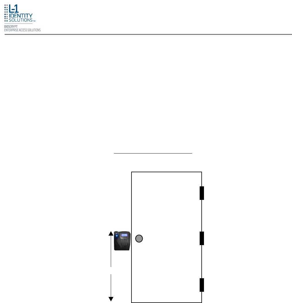
2.4. CHOOSING THE INSTALL LOCATION
V-Station 4G and V-Flex 4G devices are designed to mount on either a double-gang electrical
box or on any flat surface. Consult with local professionals regarding any building and safety
codes that might affect your installation. The correct mounting height is shown below in Figure
2-1.
Factors to consider when determining the position of a device on the wall:
• Proximity to other switch plates or fixtures (the device should ideally be mounted in-line
with other plates or fixtures)
• Distance from the floor to the top of the device (L-1 EAS recommends using a height be-
tween 48 and 54 inches).
• The device should be mounted on the knob-side of the door
• Compliance with the Americans with Disabilities Act if in the United States. Information
about this Act is available at http://www.usdoj.gov.
48 – 54”
Figure 2-1: Correct Mounting Height
Planning the Installation
Part No. 430-4G-200-00-000
© 2009, L-1 Identity Solutions Inc. 2-8
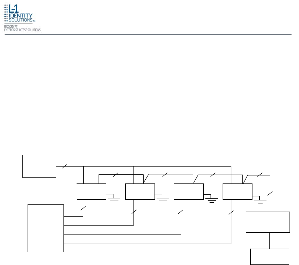
2.5. PLAN DEVICE NETWORK
The V-Station 4G and V-Flex 4G devices feature a built-in single-door relay that allows them to
control a single door lock. They can therefore function on their own or as part of a larger access
control system.
System component selection is specific to each installation, but a minimum system would
consist of a finger-scan device mounted on or near an access point, an electric lock, and ca-
bling.
A more complex system might consist of devices at multiple access points (each with an electric
door lock), a multi-point controller, networking, and a PC to run the access controller and Secu-
reAdmin Server software.
See Figure 2-2 below for an example (non-Ethernet) system diagram.
Figure 2-2: Example RS-485 System Diagram
Installation of locks and access controllers should be completed according to their respective
manufacturers' specifications and in accordance with all local codes. Final connections to the
device are explained in more detail in Chapter 4.
To avoid externally generated transients, do not run any wires near utility AC power wiring, light-
ning rod grounding wire, etc. Grounding equipment is required for ESD protection and safety.
EGND
3 3 3 3
Regulated
DC Power
Supply
Device Device Device Device
3 Data0
Data1
Wiegand GND.
2
RS-232 / RS-485
Converter
(optional)
Cat5
Twisted
Pair
Computer
Door
Controller
3 3 3
EGND EGND EGND
RS-485
RS-485
Signal GND
+(Pos)
-(Neg)
Planning the Installation
Part No. 430-4G-200-00-000
© 2009, L-1 Identity Solutions Inc.
2.6.2. RS-485
RS-485 has two distinct advantages over the more common RS-232. First, it allows
you to connect up to 31 V-Station 4G devices to a PC with an external RS-232 to RS-
485 converter (available from L-1 EAS). Second, the RS-485 specification allows for
cable run lengths up to 4000 feet (1200 meters) at modest baud rates.
An RS-485 network is required instead of RS-232 if:
• Multiple devices must be connected together so that templates can be
distributed among the devices
• The installation has only a single device, but it is over 150 feet (45 meters) from
the host PC.
2-9
2.6. CHOOSE NETWORK TYPE
If your installation requires the use of network communications, then the choice of cable, the
cable run length, the network topology, and the termination of the network are important
aspects that must be considered. The V-Station 4G and V-Flex 4G devices can be networked
using RS-232, RS-485, or Ethernet protocols.
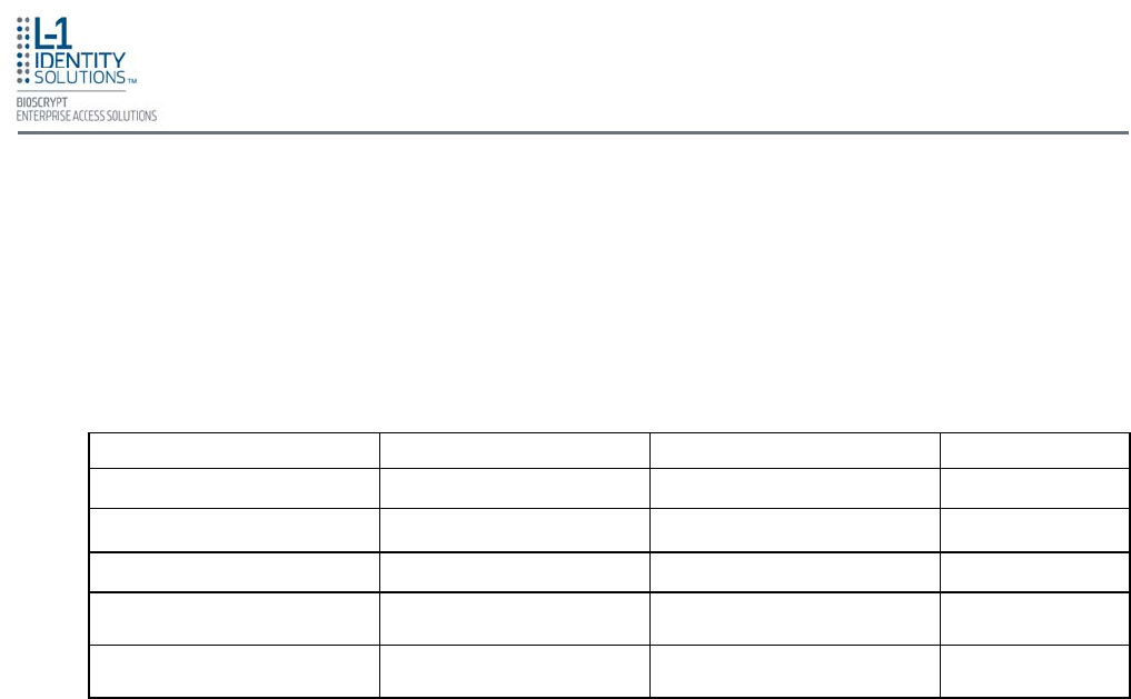
Table 2-1, below, outlines relevant parameters of the RS-485, RS-232, and 100 baseT Ethernet
communication protocols.
Table 2-1: Communications Network Comparison
Spec RS-485 RS-232 100BaseT
Mode of Operation Differential DC Coupled Single-ended DC Coupled Multi
DC Isolation No No No
Maximum Distance 4000 feet* 150 feet* 4000 feet
Number of Devices on one
line 31 1 Unlimited
Maximum Data Rate 56 Kbps
(recommended) 56 Kbps* (recommended) Auto-negotiated
2.6.1. RS-232
If your system has only one device, or a few devices (each only a short distance away
from the SecureAdmin PC) then RS-232 can be used, provided that each device can
have a dedicated RS-232 port.
With RS-232 at 9600 baud, a distance of 150 feet is possible with shielded cable, but at
56 Kbps, a maximum of only 20 feet is recommended.
Planning the Installation
Part No. 430-4G-200-00-000
© 2009, L-1 Identity Solutions Inc. 2-10
2.6.2.1. RS-485 CABLE SPECIFICATION
V-Station 4G devices provide a 2-wire, half-duplex RS-485 interface. The main
cable run should be low capacitance, twisted-pair cable, with approximately
120-ohm characteristic impedance. Category-5 rated communications cable is
used in RS-485 networks and its characteristics are defined in Table 2-2 below.
This is the recommended cabling for RS-485 communications. The cable
connection includes a differential line (+ and -) and a GND connection.
Specification Recommendation
Capacitance (conductor to conductor) <20 pF/ft.
Characteristic Impedance 100 – 120 ohms
Nominal DC resistance <100 ohms/1000 ft.
Wire gauge 24 AWG stranded
Conductors/Shielding >2 pair (shielding is recommended)
Table 2-2: Category 5 Cable Characteristics
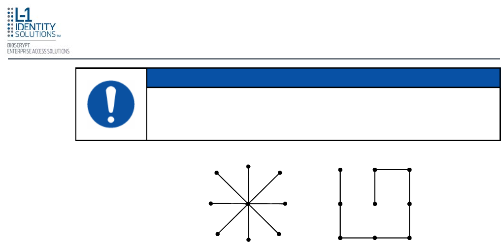
2.6.2.3. RS-485 NETWORK TOPOLOGY
Communication cables for RS-485 should be laid out in a daisy chain
configuration (See Figure 2-3 below). Long stubs or drop downs and the star
configuration should be avoided because they create discontinuities and
degrade signal quality. The star configuration usually does not provide a clean
signaling environment even if the cable runs are all of equal length. The star
configuration also presents a termination problem, because terminating every
endpoint overloads the driver. Terminating only two endpoints solves the
loading problem, but creates transmission line problems at the unterminated
ends. A true daisy chain configuration avoids these problems.
2.6.2.2. RS-485 CABLE LENGTHS
As outlined in the RS-485 specification, the total length of the communication
cable (adding up all of the segments of the run) should not exceed 1200 meters
(4000 feet). Although the RS-485 specification calls for a maximum cable length
of 1200 meters and provides a maximum baud rate well above that of the V-
Station device, a more conservative system should be configured to no more
than 1000 meters and run at a baud rate of 9600 bits per second. After the
network is configured and is running in a stable manner, the baud rate can be
increased if faster network communications are desired.
Drops (down-leads, stubs, T-connections, etc.) to equipment are not
recommended, but if required, should not exceed one foot) and should use the
same cable recommended above. On a long stub, a signal that travels down the
wire reflects to the main line after hitting the input impedance of the device at
the end. This impedance is high compared with that of the cable and the net
effect is degradation of signal quality on the bus.
Planning the Installation
Part No. 430-4G-200-00-000
© 2009, L-1 Identity Solutions Inc. 2-11
Figure 2-3: Network Topologies - Star and Daisy Chain Configurations
Star Daisy Chain
2.6.3. ETHERNET
If your system is to be configured for use over Ethernet, the wiring will be slightly
different. Communication cables for Ethernet logically form a straight line bus but the
more devices on that bus, the less efficient the network becomes due to increased
collisions, and the weaker the signal will get over distance. Repeaters can be used to
boost the signal strength; however, a better solution is to place switches at intermediate
positions along the bus. The most common Ethernet topology in use today is the star
configuration with a hub or switch in the center.
The device on the end of the network should be terminated with a 120 ohm
resistor.
NOTICE
2.6.4. WIRELESSNETWORK DESIGN CONSIDERATIONS
A wireless network of V-Station 4G and V-Flex 4G devices offers several advantages
over wired networks, such as convenience, speed of installation, and less wiring. If you
are planning to design a wireless network, consider these points:
Wireless signal interference - Metal masses such as HVAC ducts, fire doors, vents,
stairs, etc. disrupt wireless signals. Building and stairwell structures, as well as internal
building walls, also impede wireless signals. Some electrical equipment, such as
microwaves, large-screen TVs, cordless telephones are also known to affect wireless
signals. Consider the proximity of devices to these objects.
Distance from access points - How far a device is from the closest access point plays a
major factor in determining the stability and strength of the wireless signal.
Multiple Access Points - "Repeaters" or multiple access points can solve signal strength
problems that may be caused by either distance or loss due to interference.
Planning the Installation
Part No. 430-4G-200-00-000
© 2009, L-1 Identity Solutions Inc. 2-12
2.7. CHOOSE POWER SOURCE
V-Station 4G and V-Flex 4G devices can be powered by several methods:
• 12V DC regulated adapter/bullet jack
• Power Over Internet (POE) through an inline PoE 802.3af power injector
• 3-pin mini connector with dedicated power source.
Power sources should be:
• Isolated from other equipment
• Filtered
• Protected by an Uninterruptible Power Supply (UPS) or battery backup
• Protected by a voltage suppression device if transient electrical surges are an issue in the
location.
When planning a system, know the power requirement of each device. If multiple devices are to
share a common power supply, exercise care to avoid excessive voltage loss on the wires. Volt-
age loss can lead to communication problems when devices are talking and/or listening on dif-
ferent ground references.
Voltage loss is directly proportional to wire resistance and the current the wire carries. Always
place the device as close as possible to the power supply and always select a wire size
appropriate for the load. V-Station 4G devices run on DC power between 12.5 and 24 VDC.
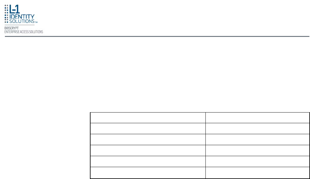
Power requirements for all V-Station 4G and V-Flex 4G models are listed below in Table 2-3.
Power Requirement: 12 watts
Input Voltage Range: 12-24.0 VDC
Peak Current (12 VDC) 1 A
Peak Current (24 VDC) 500 mA
Table 2-3: V-Station 4G and V-Flex 4G Power Requirements
Most power supplies on the market today provide good input and output isolation. However,
power supplies which do not provide isolation (or have high leakage capacitance), coupled with
accidental AC power line interchanges, present serious ground fault problems for installers. With
a ground fault, the signal reference between subsystems may be 115 VAC apart. If these sub-
systems are interconnected, the large potential difference can cause equipment damage or per-
sonal injury. L-1 EAS recommends using a dedicated regulated DC power supply.
All factory-supplied power supply assemblies are either switching or regulated linear supplies
and are isolated for safety and to minimize ground loop problems.

Install Software
Part No. 430-4G-200-00-000
© 2009, L-1 Identity Solutions Inc. 3-1
This chapter shows how to install, repair, modify, upgrade, and uninstall the SecureAdmin Server and
Client software packages.
Chapter Index
3. Install Software ................................................................................................................................... 3-2
3.1. SecureAdmin Server .......................................................................................................... 3-2
3.1.1. Repairing an Installation of SecureAdmin Server .............................................. 3-7
3.1.2. Uninstalling SecureAdmin Server ...................................................................... 3-7
3.1.3. Upgrading an Installation of SecureAdmin Server ............................................. 3-7
3.2. SecureAdmin Client ........................................................................................................... 3-8
3.2.1. Modifying an Installation of SecureAdmin Client ............................................ 3-12
3.2.2. Repairing an Installation of SecureAdmin Client ............................................ 3-12
3.2.3. Uninstalling SecureAdmin Client .................................................................... 3-12
3.2.4. Upgrading an Installation of SecureAdmin Client ........................................... 3-13
Chapter 3 - Install Software
Chapter Overview
Install Software
Part No. 430-4G-200-00-000
© 2009, L-1 Identity Solutions Inc. 3-2
3. INSTALL SOFTWARE
To install the SecureAdmin software, the user must have Administrative rights. Any software required to
install SecureAdmin is detected and installed automatically during the setup process.
To install the SecureAdmin Server software, follow these steps:
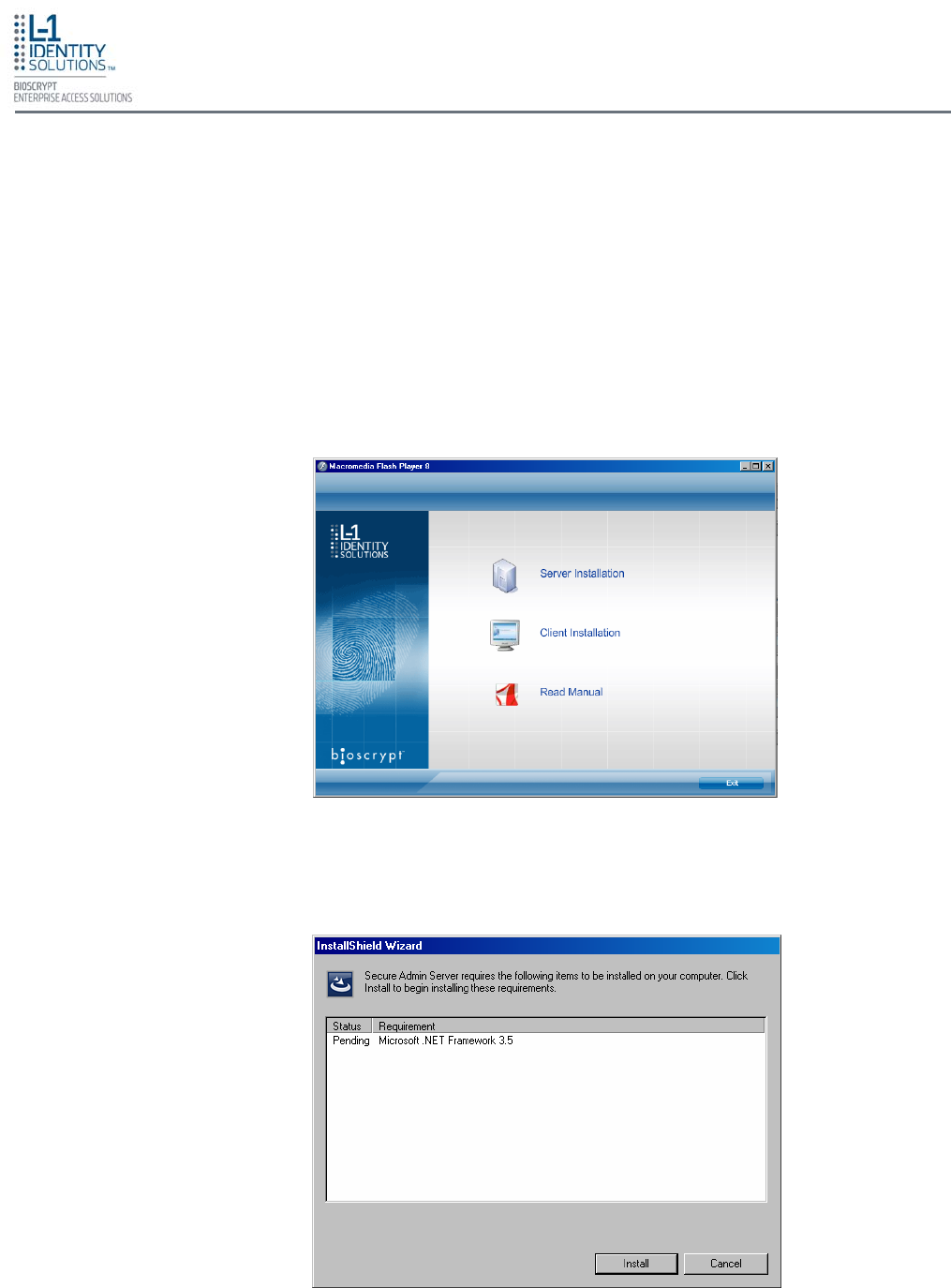
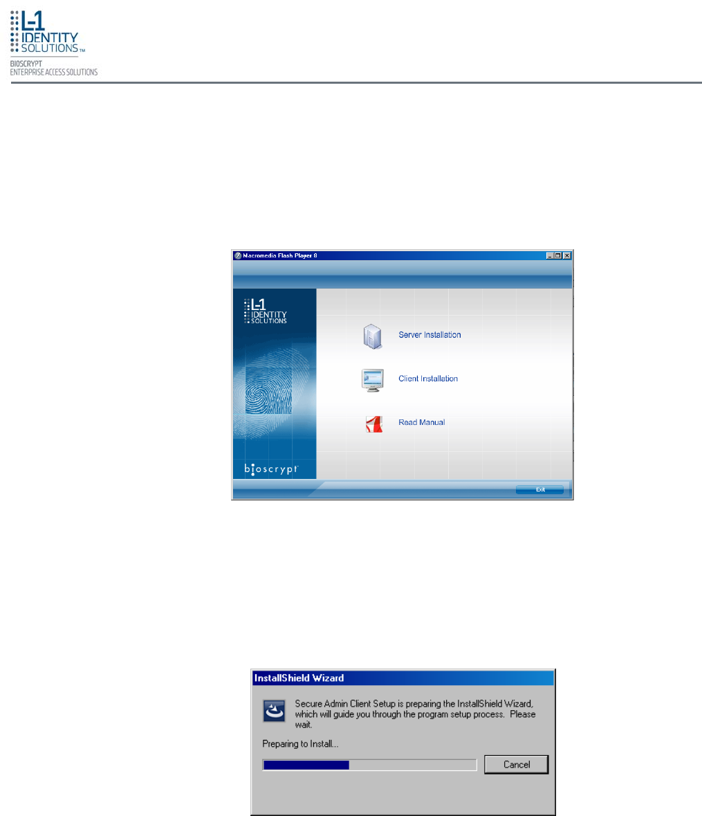
1. Insert the CD into the optical drive. If Autoplay is enabled, the installation process will start
automatically. A menu is displayed (see Figure 3-1). If Autoplay is not enabled, start the
installation process manually by doubleclicking the Setup.exe file located in the
"Bioscryptsetup" folder on the root of the CD.
3.1. SECUREADMIN SERVER
Figure 3-1: Install Menu
2. Click Server Installation. The InstallShield Wizard starts and the target system is examined
for prerequisite software. Any necessary software is listed (see Figure 3-2).
Figure 3-2: Prerequisites
Install Software
Part No. 430-4G-200-00-000
© 2009, L-1 Identity Solutions Inc. 3-3
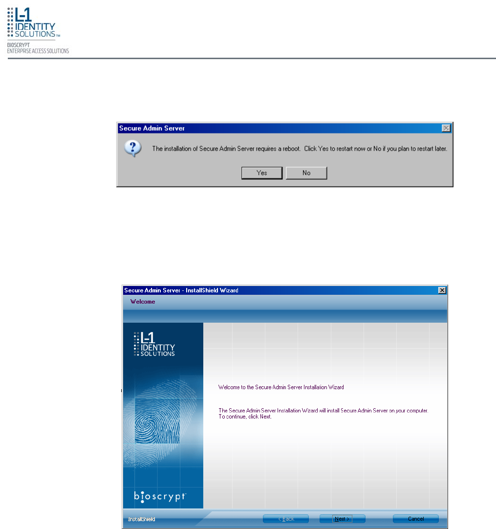
3. Click Install. Microsoft .NET Framework 3.5 is installed. Restart the computer when asked
(see Figure 3-3). The installation process continues automatically after the computer is
restarted.
Figure 3-3: Restart Message
4. Click Install. Microsoft .NET Framework 3.5 is installed. Restart the computer when asked
(see Figure 3-3). The installation process continues automatically after the computer is
restarted.
5. The Secure Admin Server Installation Wizard is displayed (see Figure 3-4). Click Next to
continue the setup process.
Figure 3-4: SecureAdmin Server Installation Wizard
Install Software
Part No. 430-4G-200-00-000
© 2009, L-1 Identity Solutions Inc. 3-4
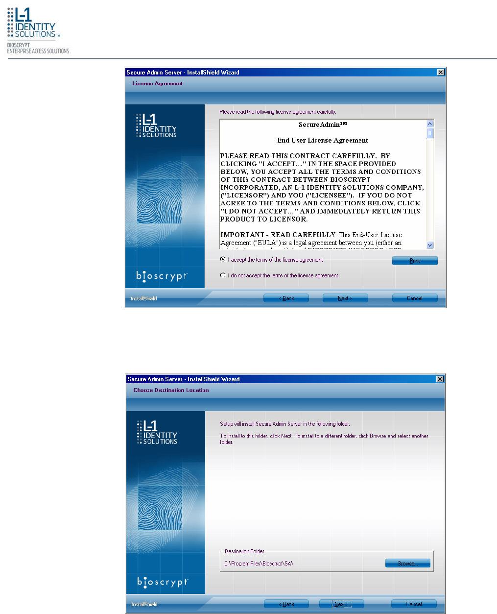
6. The L-1 EAS License Agreement is displayed. Select the appropriate radio button to agree
with the terms and then click the Next button.
Figure 3-5: SecureAdmin Server License Agreement
Figure 3-6: SecureAdmin Server Choose Destination Location
7. The Choose Destination Location screen is displayed (see Figure 3-6). Accept the default
installation folder and click the Next button or click Browse to choose your own installation
path. After you specify a destination folder, the Database Selection screen is displayed (see
Figure 3-7 on the next page).
Install Software
Part No. 430-4G-200-00-000
© 2009, L-1 Identity Solutions Inc. 3-5
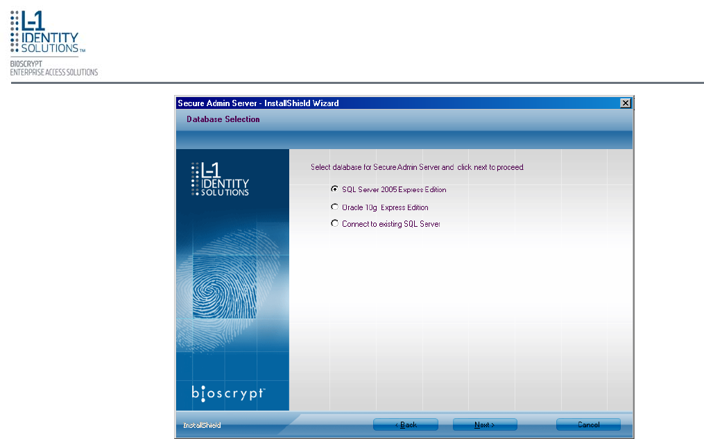
Figure 3-7: Database Selection
8. Using the radio buttons, select the type of database application you intend to work with, or
select an existing database. Click the Next button.
If you selected the SQL Server 2005 Express Edition option:
a. Select SQL Server 2005 Express Edition option to select locally available database. If a
local SQL Server 2005 Express Edition is not available on install machine, then
SecureAdmin will install SQL Server on the local machine.
b. Select Windows authentication or Database server authentication option and enter valid
login ID and password values.
c. Enter the name of the database catalog or click Browse to select an existing database
catalog.
d. Click Next to continue.
If you selected the Oracle 10G Express Edition option, it will be installed locally if it is not
already installed.
Install Software
Part No. 430-4G-200-00-000
© 2009, L-1 Identity Solutions Inc. 3-6
If you selected the option to connect to an existing SQL database:
a. Browse to the existing SQL Server available on the local network.
b. Select the Database server authentication option and enter valid Login ID and password
values.
c. Accept the default database catalog or click Browse to select a different database
catalog.
d. Click Next to continue.
9. The SecureAdmin Server Login screen is displayed. Enter a User Name and Password for
SecureAdmin server as default credentials. The password should be 8 to 30 characters long
and should contain at least one letter, one number, and one non-alphanumeric character.
10. Click Next to continue.
11. Click Finish. This completes the SecureAdmin server installation and exits the installer.
A SecureAdmin server cannot be hosted on a Virtual Machine.
The SA server listens for incoming connections from SecureAdmin clients on
TCP port 9005. This port is automatically opened as an exception in the Win-
dows Firewall during server component installation.
If you have any other firewalls (software or hardware) between the Secu-
reAdmin server and SecureAdmin clients that wish to reach it, TCP port 9005
must be opened and forwarded to the server.
V-Series 4G devices listen for connections from the server on TCP port
10001. This port must be opened on any firewalls (if any) between the server
and the devices it manages. This is unlikely in a typical LAN scenario, but
possible if server is offsite and managing devices at a remote site.
NOTICE
L-1 EAS recommends using a single installation of SecureAdmin Server and
a single database per site. Multiple databases cannot be combined.
WARNING

Install Software
Part No. 430-4G-200-00-000
© 2009, L-1 Identity Solutions Inc. 3-7
3.1.1. REPAIRING AN INSTALLATION OF SECUREADMIN SERVER
3.1.2. UNINSTALLING SECUREADMIN SERVER
3.1.3. UPGRADING AN INSTALLATION OF SECUREADMIN SERVER
To repair an installation:
1. Login as Administrator and go to the SecureAdmin installer.
2. Double-click the Setup.exe installer file to start the installer.
3. On the L1 Identity Solutions screen, select the Server Installation option.
4. On the SecureAdmin Welcome screen, select the Repair option. Click Next to
continue.
5. On the Maintenance Complete screen, click the Finish button to complete the
repair installation process.
Uninstall SecureAdmin Server by using either the Add/Remove Program function in
Windows or by using the Remove option from the installation file as outlined below.
You can also uninstall SecureAdmin Server by using the Remove option within the
installation file. Follow the instructions above for repairing an Installation. Select the
Remove option instead of the Repair option, then follow the prompts.
To upgrade a previous version of SecureAdmin Server, first uninstall the older version
using Windows Add/Remove Programs or the SecureAdmin installer, then re-install
SecureAdmin Server.
Install Software
Part No. 430-4G-200-00-000
© 2009, L-1 Identity Solutions Inc. 3-8
3.2. SECUREADMIN CLIENT
To install the SecureAdmin client software, follow these steps:
1. Insert the CD into the optical drive. If Autoplay is enabled, the installation process will start
automatically. A menu is displayed (see Figure 3-8). If Autoplay is not enabled, start the
installation process manually by doubleclicking the Setup.exe file located in the
Bioscryptsetup folder on the root of the CD.
Figure 3-8: Menu
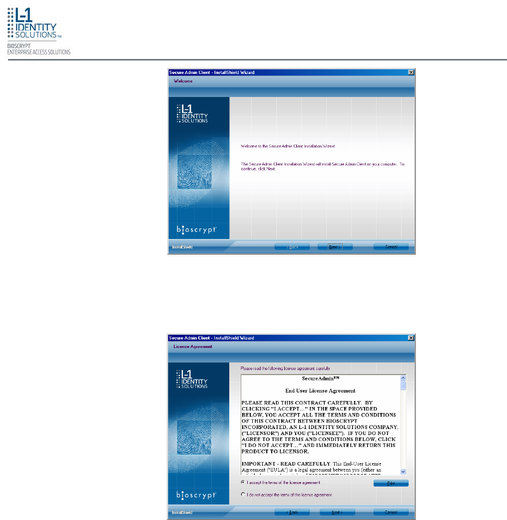
2. Click Client Installation. The InstallShield Wizard is started and the target system is
examined (see Figure 3-9 below). The Welcome screen is displayed (see Figure 3-10 on the
next page).
Figure 3-9: InstallShield Wizard
Install Software
Part No. 430-4G-200-00-000
© 2009, L-1 Identity Solutions Inc. 3-9
3. Click the Next button to continue. The License Agreement screen is displayed (see Figure
3-11).
Figure 3-10: Welcome
Figure 3-11: SecureAdmin Client License Agreement
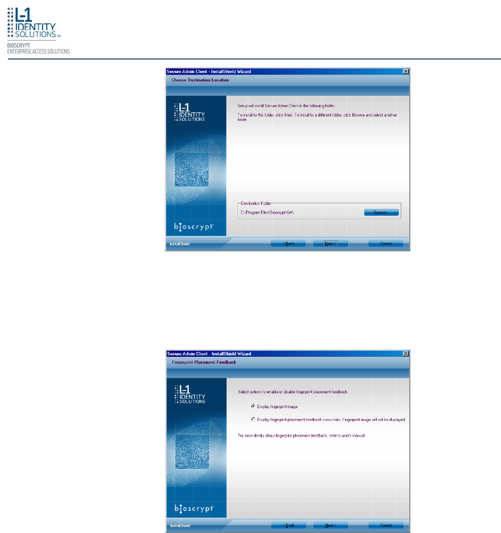
4. The L-1 EAS License Agreement is displayed. Select the appropriate radio button to agree
with the terms and then click the Next button. The Choose Destination Location screen is
displayed (see Figure 3-12) on the next page.
Install Software
Part No. 430-4G-200-00-000
© 2009, L-1 Identity Solutions Inc.
Figure 3-12: SecureAdmin Client Choose Destination Location
5. Accept the default installation folder and click the Next button or click Browse to choose
your own installation path. After you specify a destination folder, the Fingerprint Selection
Feedback selection screen is displayed (see Figure 3-13).
3-10
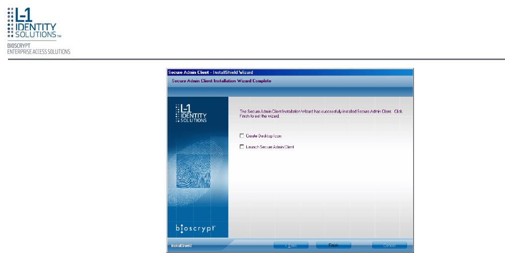
Figure 3-13: Fingerprint Placement Feedback Option Selection
6. Select the appropriate radio button to either display or to not display fingerprint data. If
Display Fingerprint Image is selected, a fingerprint will be displayed while enrolling
templates. If the Display Fingerprint Placement Feedback option is selected, then
SecureAdmin displays crosshair placement feedback instead of fingerprint images while
enrolling templates.
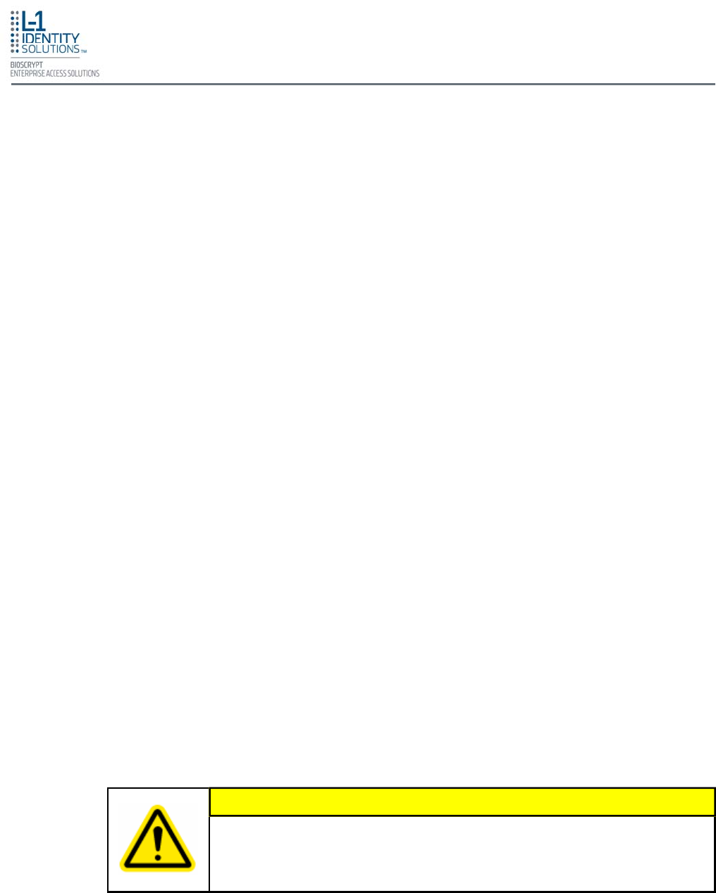
7. Click the Next button. The InstallShield Wizard completes the installation and displays a
Finished screen (see Figure 3-14 on the next page).
Install Software
Part No. 430-4G-200-00-000
© 2009, L-1 Identity Solutions Inc. 3-11
Figure 3-14: InstallShield Wizard Finished
8. Select either or both of the optional Check Create Desktop Icon and Launch Secure
Admin Client check boxes.
9. Click the Finish button.

Install Software
Part No. 430-4G-200-00-000
© 2009, L-1 Identity Solutions Inc. 3-12
3.2.1. MODIFYING AN INSTALLATION OF SECUREADMIN CLIENT
To repair an installation:
1. Login as Administrator and go to the Secure Admin installer.
2. Double-click the Setup.exe installer file to start the installer.
3. On the L1 Identity Solutions screen, select the Client Installation option.
4. On the SecureAdmin Welcome screen, select the Repair option. Click Next to
continue.
5. On the Maintenance Complete screen, click the Finish button to complete the
repair installation process.
3.2.2. REPAIRING AN INSTALLATION OF SECUREADMIN CLIENT
To modify an installation:
1. Login as Administrator and go to the Secure Admin installer.
2. Double-click the Setup.exe installer file to start the installer.
3. On the L1 Identity Solutions screen, select the Client Installation option.
4. On the Secure Admin Welcome screen, select the Modify option. Click Next to
continue.
5. Select the appropriate Fingerprint Placement Feedback option. If Display
Fingerprint Image is selected, fingerprints will be displayed while enrolling
templates. If Display Fingerprint Placement Feedback is selected, SecureAdmin
displays crosshair feedback instead of fingerprint images while enrolling templates.
6. Click Next to continue.
7. On the Maintenance Complete screen, click the Finish button to complete the
modified installation.
3.2.3. UNINSTALLING SECUREADMIN CLIENT
Uninstall SecureAdmin Client by using either the Add/Remove Program function in
Windows or by using the Remove option from the installation file.
To uninstall SecureAdmin client by using the Remove option within the installation file,
follow the instructions for repairing an installation. Select the Remove option instead of
the Repair option, then follow the prompts.

Install Software
Part No. 430-4G-200-00-000
© 2009, L-1 Identity Solutions Inc. 3-13
3.2.4. UPGRADING AN INSTALLATION OF SECUREADMIN CLIENT
To upgrade a previous version of SecureAdmin Client, first uninstall the older version
using Windows Add/Remove Programs or the SecureAdmin installer, then re-install the
new version of SecureAdmin Client.

Install Software
Part No. 430-4G-200-00-000
© 2009, L-1 Identity Solutions Inc. 3-14
This page left blank intentionally

Install Hardware
Part No. 430-4G-200-00-000
© 2009, L-1 Identity Solutions Inc. 4-1
This chapter explains how to install a V-Station 4G or V-Flex 4G device, how to mount a wall plate, how
to attach a device to a wall plate, and how to make the required electrical connections to the device.
Chapter Index
4. Install Hardware ................................................................................................................................. 4-2
4.1. Wall Mounting Schemes .................................................................................................... 4-2
4.2. Installing a Mounting Plate ................................................................................................. 4-2
4.3. Installation Hardware ......................................................................................................... 4-5
4.4. Attach Device to Mounting Plate ........................................................................................ 4-5
4.5. Connect Device to Earth Ground ....................................................................................... 4-6
4.6. Connect Device to Power Source ...................................................................................... 4-7
4.7. Connect Device to Network ............................................................................................... 4-9
4.7.1. Ethernet Network Connections .......................................................................... 4-9
4.7.2. RS-232/RS-485 Network Connections .............................................................. 4-9
4.7.3. Wireless Network Connections ....................................................................... 4-11
4.8. Connect Device to Door .................................................................................................. 4-12
4.9. Aux Port .......................................................................................................................... 4-14
4.10. Install Ferrite Core ........................................................................................................ 4-15
CHAPTER 4 - INSTALL HARDWARE
Chapter Overview
Install Hardware
Part No. 430-4G-200-00-000
© 2009, L-1 Identity Solutions Inc. 4-2
4. INSTALL HARDWARE
The V-Station 4G and V-Flex 4G devices are mounted, by use of a mounting plate, either di-
rectly to a wall or to an electrical box recessed in the wall. The V-Station 4G device can be flush
mounted only. The V-Flex 4G device can be either flush or recess-mounted on a wall. Refer to
Figures 4-1 and 4-2 on the next page.
4.1. WALL-MOUNTING SCHEMES
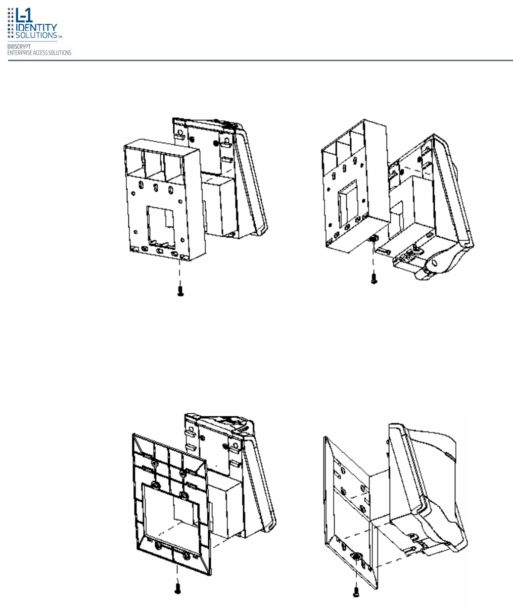
4.2. INSTALLING A MOUNTING PLATE
The procedure for mounting a wall plate directly to a wall is as follows:
1. Hold the mounting plate onto the wall in the desired location, trace the square hole that will
be cut out, and mark the mounting screw locations. Note that for the V-Flex 4G, the large
square hole is at the bottom and for the V-Station 4G the hole is to the right.
2. Cut out the square hole with a jigsaw or drywall saw. If the V-Flex 4G device is to be recess-
mounted, cut out a hole in the drywall to accommodate the rear extension on the device
housing.
3. Drill holes for the nylon wall anchors and install them.
4. Fish wires through the wall to the square hole.
5. Align the hole in the wall plate with the hole in the wall.
6. Fasten the mounting plate to the nylon wall anchors in the wall with the provided screws.
If the V-Flex 4G device is to be recess-mounted on an electrical box, a double gang box is
required to accept the rear extension of the housing.
If mounting the V-Station 4G device to an electrical box, attach the mounting plate to a single
gang box and use wall anchors on the remaining four holes for additional security.
To install the mounting plate on to an electrical box, screw the mounting plate to the box with the
provided 6-32 screws.
When installing a recess-mounted V-Flex 4G device, be careful not to dam-
age the tamper switch, as careless handling can shear it off.
CAUTION
Install Hardware
Part No. 430-4G-200-00-000
© 2009, L-1 Identity Solutions Inc. 4-3
Figure 4-1: V-Flex 4G Flush-mount Mounting Plate
Figure 4-2: V-Flex 4G Recessed-mount Mounting Plate
Install Hardware
Part No. 430-4G-200-00-000
© 2009, L-1 Identity Solutions Inc. 4-4
The V-Station 4G device can only be flush mounted.
NOTICE
Figure 4-3: V-Station 4G Mounting Plate
Install Hardware
Part No. 430-4G-200-00-000
© 2009, L-1 Identity Solutions Inc. 4-5
4.3. INSTALLATION HARDWARE
Quantity Component
Hardware
1 Wall mounting plate/mullion mounting plate
6 #6-32 3/4" Philips pan-head screw
6 #6 1" Philips pan-head self-tapping screws
6 #4-8 1" nylon wall anchors
The hardware shown above is provided to mount the mounting plate to the wall and the V-
Station 4G or V-Flex 4G device to the mounting plate.
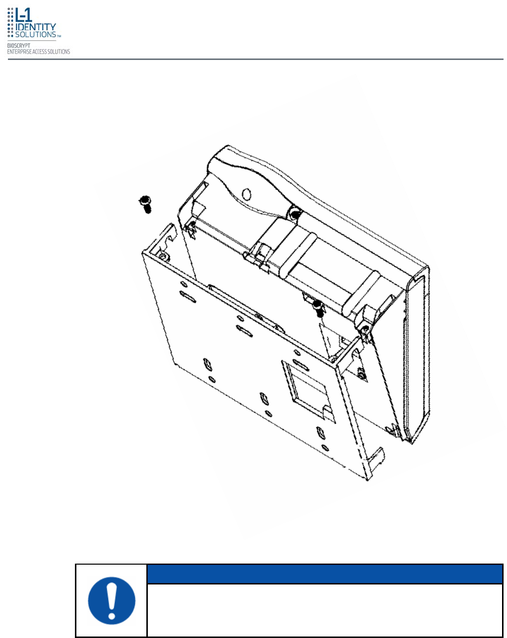
4.4. ATTACH DEVICE TO MOUNTING PLATE
Once all the electrical connections have been made to the device, it can be attached to the
mounting plate as follows:
For the V-Flex 4G, insert the four hooked protrusions on the rear of the device into the corre-
sponding slots on the mounting plate. Hold the device against the plate and gently press it in a
downward direction to engage the hooks. Insert the star-shaped screw at the bottom center of
the mounting plate and tighten with the wrench provided. Do not over-tighten.
For the V-Station 4G, hold the device with the top slightly tilted toward you, at about a 30-degree
angle to the wall. Hold the bottom of the device against the mounting plate and lower it so that
the two hooks on the bottom of the mounting plate engage the corresponding slots on the de-
vice. When the hooks are properly engaged, the top of the device can be pivoted up against the
mounting plate. It will drop down slightly, locking itself in the closed position, and should be se-
cured in this position with the star-shaped screws in the holes at the right and left ends on the
bottom of the device. Do not over-tighten.
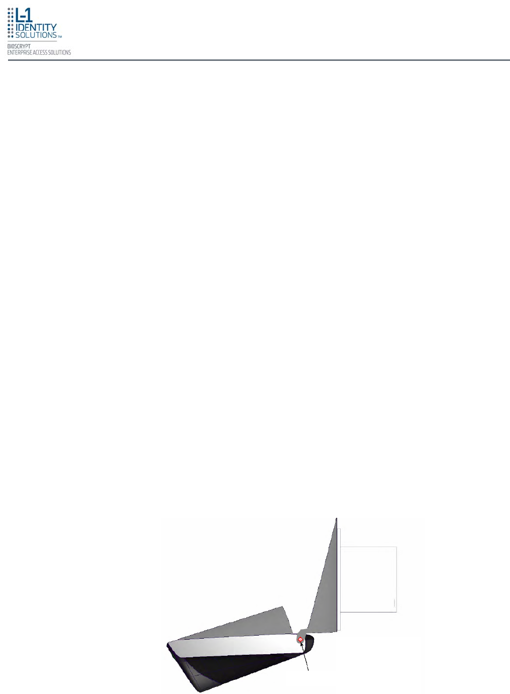
With the securing screws removed, the V-Station 4G device can be pivoted down 90 degrees
from the wall, as shown in Figure 4-4, to allow access for making connections, etc. The device
can be removed from the mounting plate by tilting it at an angle approximately 30 degrees to the
wall and gently lifting it up off the hooks on the mounting plate.
Pivot Point
Figure 4-4: Device Open for Installation or Service
Install Hardware
Part No. 430-4G-200-00-000
© 2009, L-1 Identity Solutions Inc. 4-6
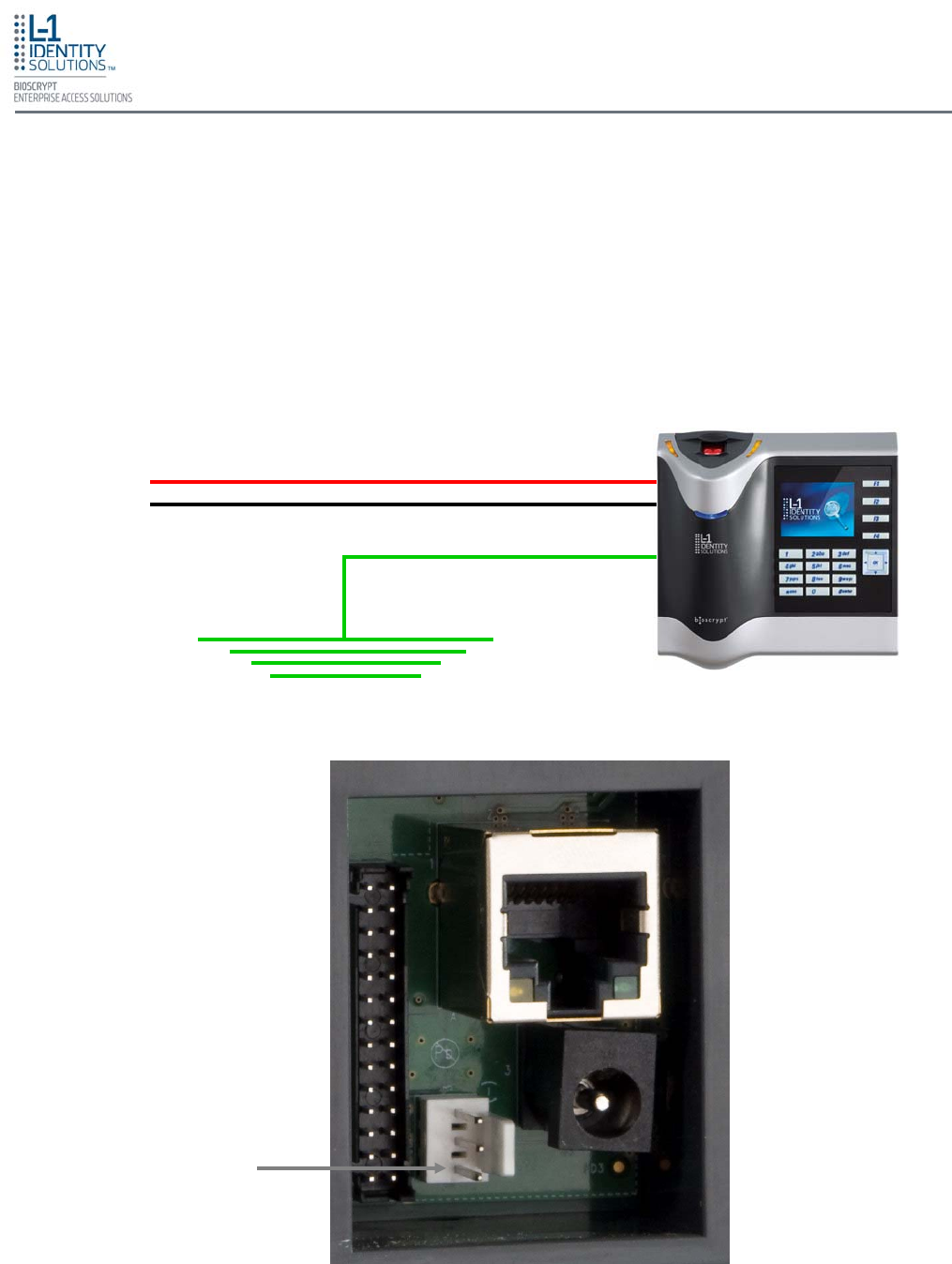
3-pin Mini Connector
(Pin 3 is Earth Ground)
The device's ground connection must be properly connected to avoid damage by Electro-Static
Discharge (ESD).
To connect the device to earth ground, connect Pin 3 of the mini connector (located on the rear
of the device) to earth ground. This terminal should not be connected to the neutral, to the cable
shield, or to any other wire except earth ground. See Figure 4-5, below. The connection to earth
ground should use the largest wire possible (12 AWG) and be as close to the termination point
(water pipe, etc.) as possible.
Power
Power
Earth Ground
4.5. CONNECT DEVICE TO EARTH GROUND
Figure 4-5: Earth Ground Connection
Install Hardware
Part No. 430-4G-200-00-000
© 2009, L-1 Identity Solutions Inc. 4-7
The V-Station 4G and V-Flex 4G devices can be powered either by 12V DC power sources or
through a Power Over Ethernet (PoE) injector.
The two options for providing 12V power to V-Station 4G and V-Flex 4G devices are by using an
external wall plug-in adapter, as shown in Figure 4-6, or through external wiring and a mini plug
as shown in Figure 4-7.
4.6. CONNECT DEVICE TO POWER SOURCE
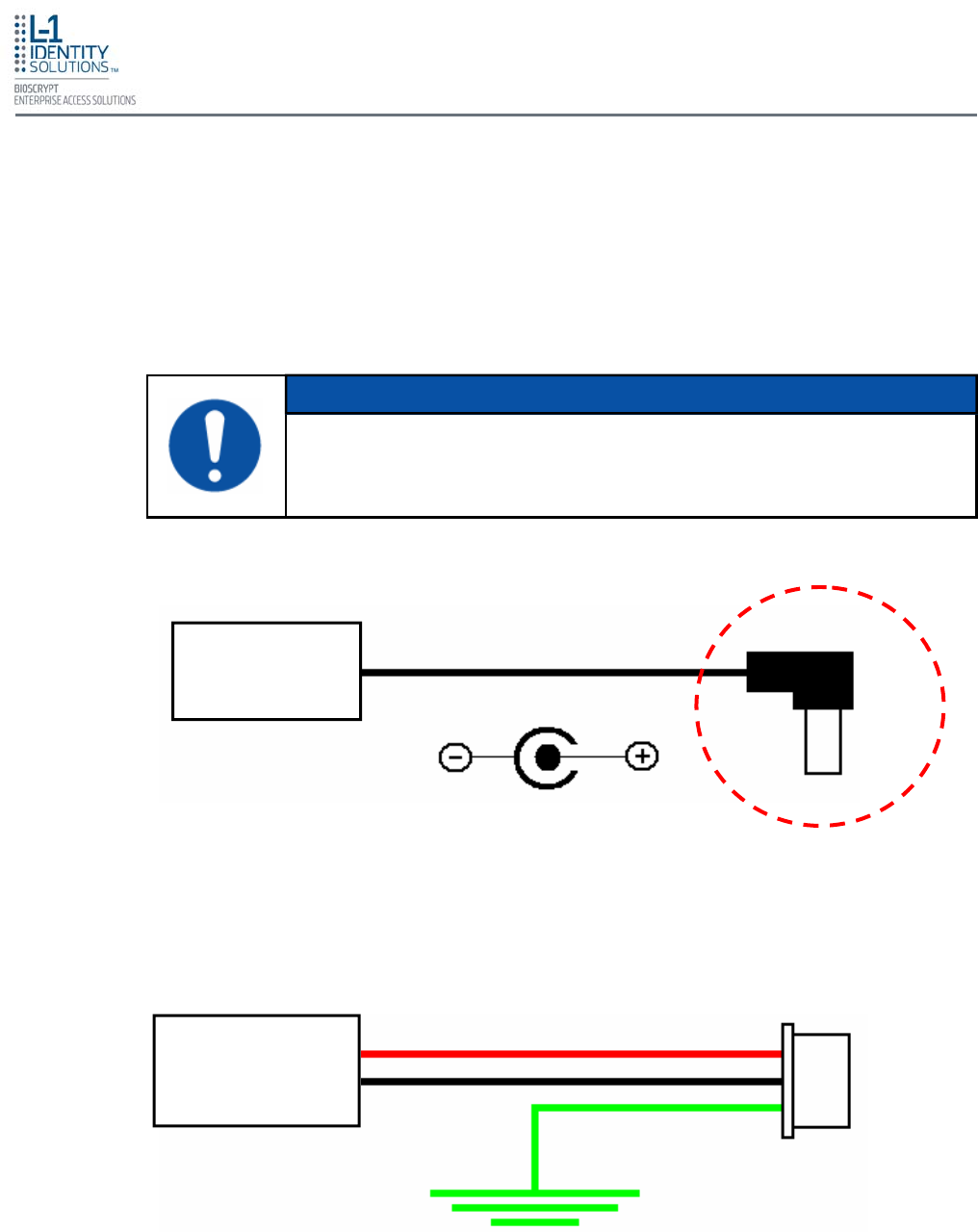
2.1 mm Tip
Center = Positive
Plug-In 12 VDC
Adapter
1 – PWR
2 – GND
3 – EARTH
Earth Ground Mini
Connector
External 12 VDC
Power Source
Figure 4-6: Connections for an External Wall Adapter
Figure 4-7: Connections for an External Power Source
Both devices must be earth grounded using the 3-pin mini-connector, regard-
less of what power source is being used.
NOTICE
Install Hardware
Part No. 430-4G-200-00-000
© 2009, L-1 Identity Solutions Inc. 4-8
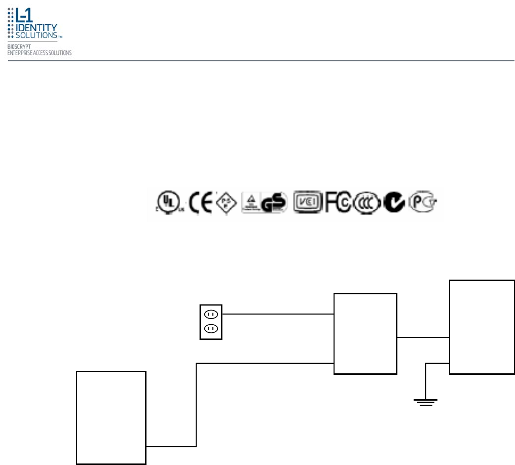
The V-Station 4G and V-Flex 4G devices both support Power over Ethernet (PoE), using their
RJ-45 Ethernet interface. When these devices are to be powered over Ethernet, an IEEE
802.3af compliant Active Midspan Injector must be used (see Figure 4-9). Such an injector is not
supplied with L-1 EAS products. An example of a suitable PoE injector is Model No. AT-6101G
from Allied Telesis Inc. (http://www.alliedtelesis.com).
Any such device should carry at least one of the certifications shown below in Figure 4-8 and
should be FCC listed.
Figure 4-8: Certification Marks
Figure 4-9: Power Over Ethernet Connection
Specifications for suitable PoE Injectors are as follows:
Input voltage: 90-264 VAC, 60 Hz
Input current: 0.4A @ 100 VAC
Output voltage: -48 VDC
Output current: 0.32A
Power: 15.36 W
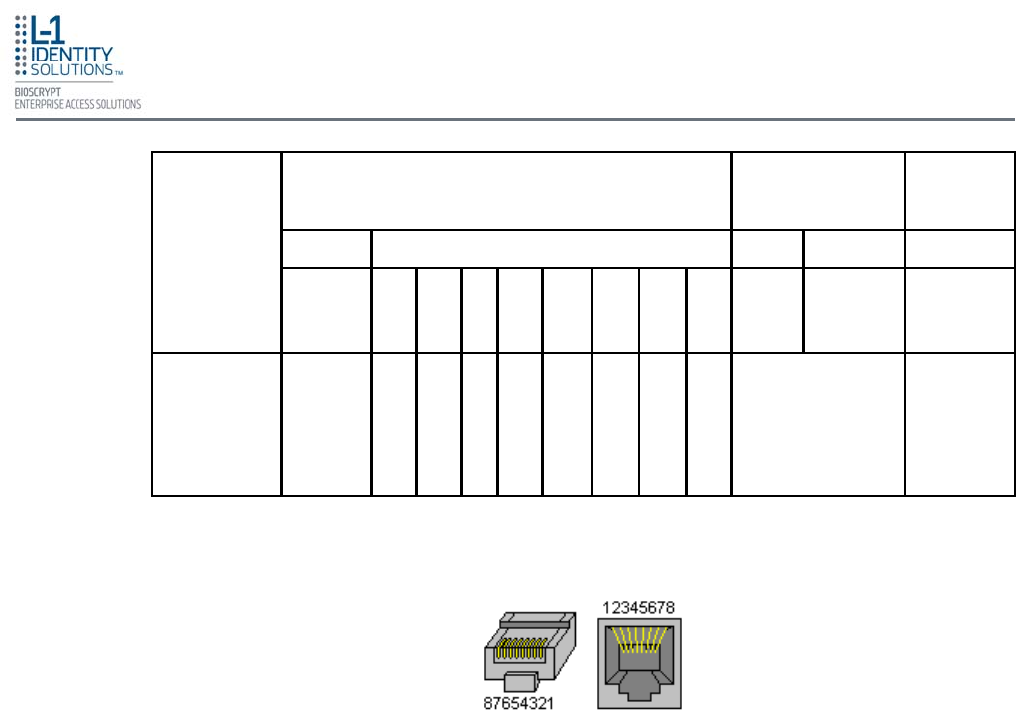
For Power over Ethernet, RJ-45 pin numbers 4, 5 are considered VB1(+) positive DC supply,
and pin numbers 7, 8 are VB2(-) DC return.
Detailed RJ-45 pin assignments for PoE are given in Table 4-1 (on the next page), and the
physical location of the pins in the RJ-45 connector is shown in Figure 4-11 (on the next page).
PoE
Injector
V-Station
4G
Host
Computer
110 VAC
CAT5
RJ45
RJ45
RJ45
RJ45
Earth Ground
Install Hardware
Part No. 430-4G-200-00-000
© 2009, L-1 Identity Solutions Inc. 4-9
STANDARD
SOURCE LOAD REMARKS
Ethernet RJ-45 connector pin number
Source
Voltage 1 2 3 4 5 6 7 8 Load
Voltage DC Load
Connector
IEEE 802.3af
using spare
pairs
48 V DC,
protected RX RX TX DC+ DC+ TX DC- DC- (embedded)
Industry
Standard for
embedded
PoE
Figure 4-10: RJ45 Pin Location
Table 4-1: PoE Pin Assignments
The V-Station 4G and V-Flex 4G devices support both RS-232/RS-485 and Ethernet 10baseT
and 100baseTX network protocols.
4.7. CONNECT DEVICE TO NETWORK
Ethernet connections to the device are made through a standard RJ-45 connector on
the back of the device. Refer to Figure 4-10 and Table 4-1 for RJ-45 pin assignments
and locations.
4.7.1. ETHERNET NETWORK CONNECTIONS
To connect a device to an RS-232 or RS-485 network, connect the appropriate wires to
the provided pigtail in accordance with the pin-out diagram in Figure 4-11 (next page).
4.7.2. RS-232/RS-485 NETWORK CONNECTIONS
Install Hardware
Part No. 430-4G-200-00-000
© 2009, L-1 Identity Solutions Inc. 4-10
Figure 4-11: Pin-out Diagram
When connecting the device to the network, the following procedures must be followed:
• Use Category 5 cabling with a characteristic impedance of 120 ohms for RS-485
networks. Category 5 cables with a characteristic impedance of 100 ohms can also
be used, but with lower performance.
• Cable manufacturers provide cables with multiple twisted pairs designed for this
type of communication (characteristic impedance is 120 ohm).
• Unused pairs within the cable must be terminated with characteristic impedance
(100 or 120 ohm) on both ends.
• AWG 24 should be considered as the minimum gauge.
• Choose one twisted pair of conductors to use for RS-485 differential connections,
other conductors should be used for Signal Ground (RS-485 GND on Weidmuller
connection).
• The RS-232 to RS-485 converter must support Sense Data to be able to switch
from Send to Receive mode.
• Check each device's cabling for ground faults before connecting to an RS-485 net-
work.
• Each device should have pin 3 of the mini-connector connected to earth ground.
After all devices are configured and connected to the RS-485 network, the baud rate
can be increased to the highest supported rate (some experimentation might be re-
quired).
Connector Pin No. Wire Color Connector Pin No. Wire Color
Pin1 (RS485A) Blue Pin2 (RS232_RX) Violet/White
Pin3 (RS485B) Blue/Black Pin4 (RS232_TX) Violet
Pin5 (SGND) Black/Red Pin6 (SGND) Black/Red
Pin7 (WIEGAND_LED_IN0) Grey/Black Pin8 (WIEGAND_DIN0) Green/White
Pin9 (Not Connected) Pin10 (WIEGAND_DIN1) White/Black
Pin11 (WIEGAND_LED_OUT0) Brown/Green Pin12 (WIEGAND_DOUT0) Green
Pin13 (WIEGAND_LED_OUT1) Brown/Black Pin14 (WIEGAND_DOUT1) White
Pin15 (TTLOUT_0H) White/Brown Pin16 (WGND) Black/White
Pin17 (TTLOUT_0L) White/Red Pin18 (TTLIN0) Yellow/Blue
Pin19 (TTLOUT_1H) Brown/White Pin20 (TTLIN1) Blue/Brown
Pin21 (TTLOUT_1L) Yellow/Black Pin22 (TTLIN2) Brown/Violet
Pin23 (TTLOUT_2H) Grey/Orange Pin24 (TTLGND) Green/Brown
Pin25 (TTLOUT_2L) White/Green Pin26 (RELAY_NC) Orange
Pin27 (RELAY_NO) Yellow Pin28 (RELAY_COM) Grey
Install Hardware
Part No. 430-4G-200-00-000
© 2009, L-1 Identity Solutions Inc. 4-11
For installations on a wireless network, the same connection procedures should be
followed to connect the device to the wireless network devices. After the wireless
network has been installed, it needs to be set up either through SecureAdmin (see
Chapter 7 in the Operator's Manual) or through the front panel of the V-Station 4G
device.
To set up wireless operation through the front panel of a V-Station 4G device, perform
the following steps:
1. Power up the device.
2. Ensure that the wireless network is functioning.
3. Use one of these supported modes:
• WEP Open
• WPA Personal
• WPA2 Personal.
4.7.3. WIRELESS NETWORK CONNECTIONS
4. Enter the Admin menu on the device by pressing the Left arrow and Enter keys
simultaneously.
5. Key in the Admin password (default is "0000") and press OK.
6. Select the Communications icon and press OK
7. Select "Network Interface" and press OK.
8. Select "WLAN" and press OK.
9. Select "Scan for wireless network" and press OK.
10. Select "Enable" and press OK.
11. Select "Encryption mode" and press OK.
12. Choose the type of encryption your network is using and press OK.
13. Enter the key.
14. Select "DHCP" or "Static" and press OK. If you selected "DHCP", the device
reboots. Afterwards, it will have a dynamic IP address. If you selected "Static IP",
specify an IP, a Net Mask, a Gateway, and then press OK. The device reboots.
L-1 EAS does not recommend using the "No encryption" mode.
NOTICE
Install Hardware
Part No. 430-4G-200-00-000
© 2009, L-1 Identity Solutions Inc. 4-12
After rebooting, check for a "Wireless" icon on the device's LCD. Press the Left arrow
key to display Wireless info. If wireless operation is set up correctly, pertinent wireless
network information is displayed. If no information is displayed, then the wireless setup
is not set correctly.
SecureAdmin can scan for and auto-detect wireless devices. If you want to use
SecureAdmin to scan for wireless devices, ensure that the "multicasting" option is
enabled in your router.
The maximum recommended distance from an access point is 25 feet.
NOTICE
The V-Station 4G and V-Flex 4G devices incorporate an internal relay that enables them to op-
erate a deadbolt/door strike directly.
4.8. CONNECT DEVICE TO DOOR
The snubber diode and DC power supply for the deadbolt/door strike are not
supplied with the V-Station 4G and V-Flex 4G devices. The power supply
should be specified in accordance with the voltage and current requirements
of the deadbolt/door strike, but it must be ensured that the current to operate
the deadbolt/door strike does not exceed 170 mA.
CAUTION
Assuming the current drawn by the deadbolt/door strike is less than 170 mA, the connections
between the V-Station 4G or V-Flex 4G device, deadbolt/door strike, and power supply for the
deadbolt/door strike should be made as shown in Figure 4-12 (on the next page). Note that a
snubber diode (1N4007 or equivalent) must be connected across the deadbolt/door strike to
protect the DC power supply from inductive kickback.
If the current required to operate the deadbolt/door strike exceeds 170 mA, an external relay
must be used in conjunction with the V-Station 4G or V-Flex 4G device. The external relay must
be specified so that its contacts are rated to carry the current required by the deadbolt/door
strike, and that the current required to operate its energizing coil is within the 170 mA capacity
of the V-Station 4G or V-Flex 4G device's internal relay.
The internal relay is limited to a maximum current of 170 mA. If the deadbolt/
doorstrike to be controlled draws more than 170 mA, damage to the device
may occur. If the deadbolt/door strike load exceeds 170 mA, an external re-
lay must be used, as described below.
Do not use the same power supply to power a V-Series 4G device and a
door strike.
WARNING
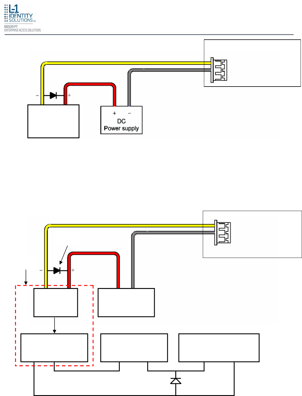
Install Hardware
Part No. 430-4G-200-00-000
© 2009, L-1 Identity Solutions Inc. 4-13
Figure 4-12: Connections for Internal Relay Operation
The power supply for the external relay must be chosen to match the operating voltage and cur-
rent of the external relay coil, but its voltage must not exceed the V-Station 4G or V-Flex 4G de-
vice's internal relay maximum voltage rating of 250 volts.
The external relay should be connected in accordance with Figure 4-13 below. Note that snub-
ber diodes (1N2007 or equivalent) should be connected across the external relay coil and the
deadbolt/door strike.
V-Station 4G or V-Flex 4G
Deadbolt/Door
strike
Max load 170 mA
27 - N.O. (Normally Open)
28 - Common
COM N.O. N.C.
Deadbolt/Door Strike
Con 1 Con 2
DC Power Supply
-DC +DC
Snubber Diode
1N4007
27 - N.O. (Normally Open)
28 - Common
V-Station 4G or V-Flex 4G
External
Relay Coil
+ –
DC Power Supply
for External Relay
External Relay Contacts
External
Relay
Snubber
Diode
Figure 4-13: Connections for External Relay Operation
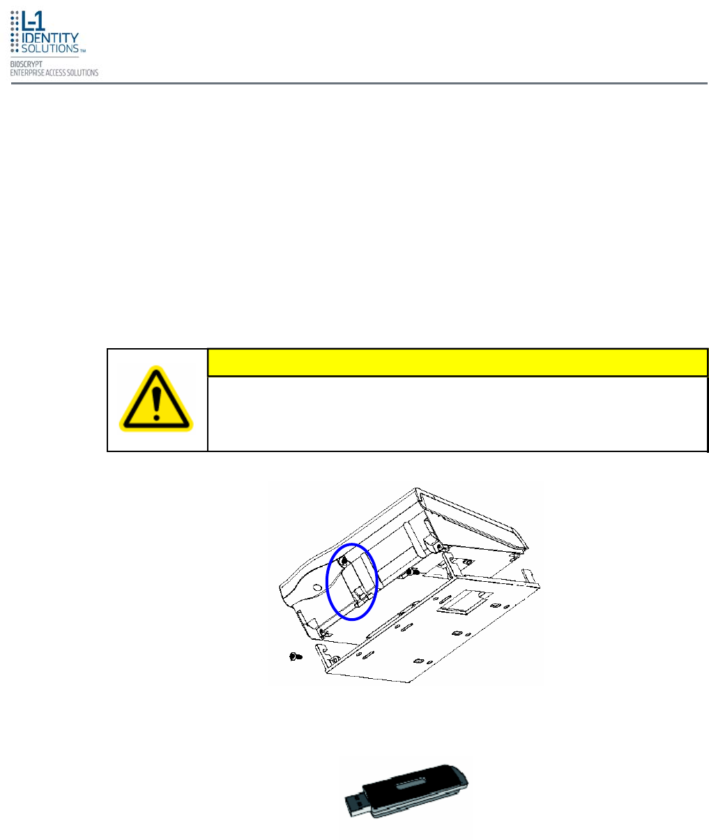
Install Hardware
Part No. 430-4G-200-00-000
© 2009, L-1 Identity Solutions Inc. 4-14
The Aux port is a USB 2.0 auto-negotiate connector located on the bottom of the device (see
Figure 4-14). To access the Aux port, the Aux port door must first be removed. Use the provided
pin-in-hex security key to remove the #6-32 security screw retaining the plastic Aux port door.
Gently remove the plastic Aux port door to reveal the USB connector.
To attach a USB memory key (see Figure 4-15) or other "gadget" serial device by way of the
Aux port, use the USB Type A female to USB Micro A/B male adapter cable provided in the in-
stallation kit.
The Aux port is used to transfer files to and from the device. Audio, images, firmware, logs, and
configuration files can be transferred quickly and easily to a device without the need for a com-
puter.
4.9. AUX PORT
Current rating of the Aux port is not to exceed 100 mA Maximum.
CAUTION
Figure 4-14: Location of Aux Port (V-Station 4G)
Figure 4-15: USB Memory Key
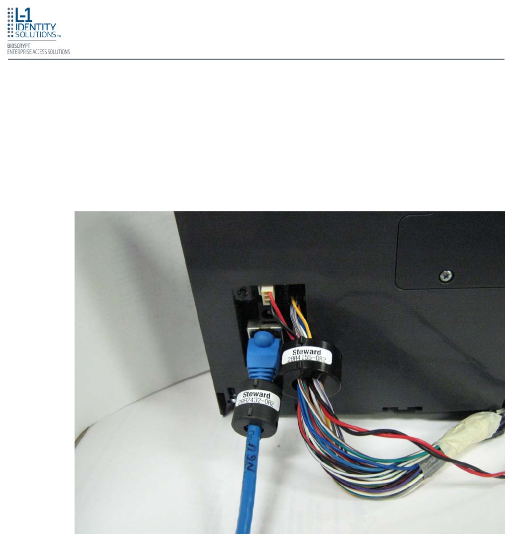
Install Hardware
Part No. 430-4G-200-00-000
© 2009, L-1 Identity Solutions Inc. 4-15
In order for the V-Station 4G and V-Flex 4G devices to comply with FCC Class B & CISPR 22
Class B regulations, the installer and/or end user is required to use the supplied Ferrite Material
on the Ethernet, DC, and all I/O cables exiting the rear of the device. This ferrite material is lo-
cated within the installation kit that is supplied with each product.
Ethernet Ferrite P/N: STEWARD 28A2432-0A2
DC & I/O Lines P/N: STEWARD 28A4155-0A2
Install the ferrite cores as close to the device as possible, as shown in Figure 4-16 below.
4.10. INSTALL FERRITE CORE
Figure 4-16: Installation of Ferrite Cores

Install Hardware
Part No. 430-4G-200-00-000
© 2009, L-1 Identity Solutions Inc. 4-16
This page left blank intentionally

System Start-up Procedures
Part No. 430-4G-200-00-000
© 2009, L-1 Identity Solutions Inc. 5-1
5. System Start-up Procedures .............................................................................................................. 5-2
5.1. System Start-up Overview ................................................................................................. 5-2
5.2. Device Configuration Check .............................................................................................. 5-2
5.3. RS-232 to RS-485 Converter Ground Fault Check ........................................................... 5-3
5.4. Device Ground Fault Check................................................................................................ 5-3
This chapter explains the various start-up procedures and checks that should be performed before
applying power to a device.
Chapter Index
CHAPTER 5 - SYSTEM START-UP PROCEDURES
Chapter Overview

System Start-up Procedures
Part No. 430-4G-200-00-000
© 2009, L-1 Identity Solutions Inc. 5-2
5. SYSTEM START-UP PROCEDURES
To avoid the need for difficult troubleshooting, system start-up must follow this step-by-step
procedure. Never wire up a system and apply power to it all at once.
L-1 EAS recommends always following these system start-up steps:
1. Do not apply power to any device.
2. Check all wiring and device configurations.
3. Disconnect all devices from the communication line.
4. Check the supply voltage for correct voltage.
5. Power up the PC running SecureAdmin.
6. Power up the RS-232 to RS-485 converter (if installed).
7. Configure SecureAdmin.
8. Perform a ground fault check for the converter (if installed).
9. Connect the PC and converter (if installed) to the communication line.
10. Verify that the device powers up correctly, but do not connect it to the communication line.
The power LED should be illuminated. Check the power lines with a voltmeter.
11. Perform a ground fault check for the device (if using RS-485, see Section 5.4 on next page).
12. Connect the device to the communication line.
13. Verify that the device communicates with SecureAdmin.
14. If there are more device, repeat Steps 10 through 13 for each device.
5.1. SYSTEM START-UP OVERVIEW
Devices must be configured correctly before they can communicate. Common problems
include incorrect Host Port Protocol settings, mismatched Baud rates, and incorrect device Net-
work IDs. Each device sharing a communication line must have a unique device Network ID.
5.2. DEVICE CONFIGURATION CHECK

System Start-up Procedures
Part No. 430-4G-200-00-000
© 2009, L-1 Identity Solutions Inc. 5-3
Before a device can be connected to an RS-485 subsystem, it must be checked for ground
faults. An uncorrected ground fault can damage all devices connected to the RS-485
communication line.
To check for a ground fault on the RS-232 to RS-485 converter:
1. Apply power to the RS-232 to RS-485 converter.
2. Connect the signal ground of the RS-485 line through a 10k ohm current-limiting resistor to
the signal ground of the RS-232 to RS-485 converter. There should be no more than 1 volt
across the resistor.
5.3. RS-232 TO RS-485 CONVERTER GROUND FAULT CHECK
To check for a ground fault on a new V-Station 4G or V-Flex 4G device:
1. Apply power to all devices already successfully connected to the RS-485 line.
2. Power up the new device but do not connect it to the RS-485 line.
3. Connect the signal ground of the RS-485 line through a 10k ohm current-limiting resistor to
the signal ground of the V-Station 4G device.
4. There should be no more than 1 volt across the resistor. If there is, find and clear the fault.
5. Repeat Steps 1 through 3 with each of the RS-485 signal lines (+ and -).
6. Connect the new device to the RS-485 line only if no ground fault is found.
5.4. DEVICE GROUND FAULT CHECK

System Start-up Procedures
Part No. 430-4G-200-00-000
© 2009, L-1 Identity Solutions Inc. 5-4
This page left blank intentionally

Configure Device
Part No. 430-4G-200-00-000
© 2009, L-1 Identity Solutions Inc. 6-1
6. Configure Device................................................................................................................................. 6-2
6.1. Register Device................................................................................................................... 6-2
This chapter explains how to configure a device and calibrate a device sensor using the SecureAdmin
Client application.
Chapter Index
CHAPTER 6 - CONFIGURE DEVICE
Chapter Overview
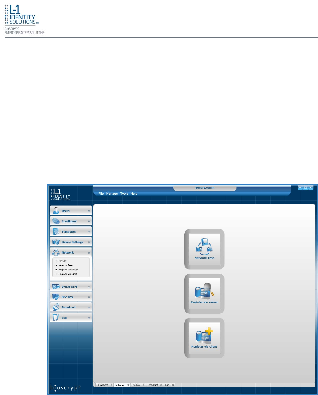
Configure Device
Part No. 430-4G-200-00-000
© 2009, L-1 Identity Solutions Inc. 6-2
5. CONFIGURE DEVICE
V-Station 4G and V-Flex 4G devices must be configured before use. This includes setting various com-
munication parameters and calibrating the device's sensor
After a device is physically installed, it must registered. This can be done several ways -- when
a device is connected by means of a network (this is the recommended method), or when the
device is connected directly to the host computer upon which SecureAdmin is running.
To register a networked device:
1. Launch SecureAdmin.
2. Double-click the Network tab. Three buttons are displayed (see Figure 6-1).
5.1. REGISTER DEVICE
3. Click the Register via Server button. A Register via Server dialog box is displayed (see
Figure 6-2 on the next page).
Figure 6-1: Network Sidebar Tab
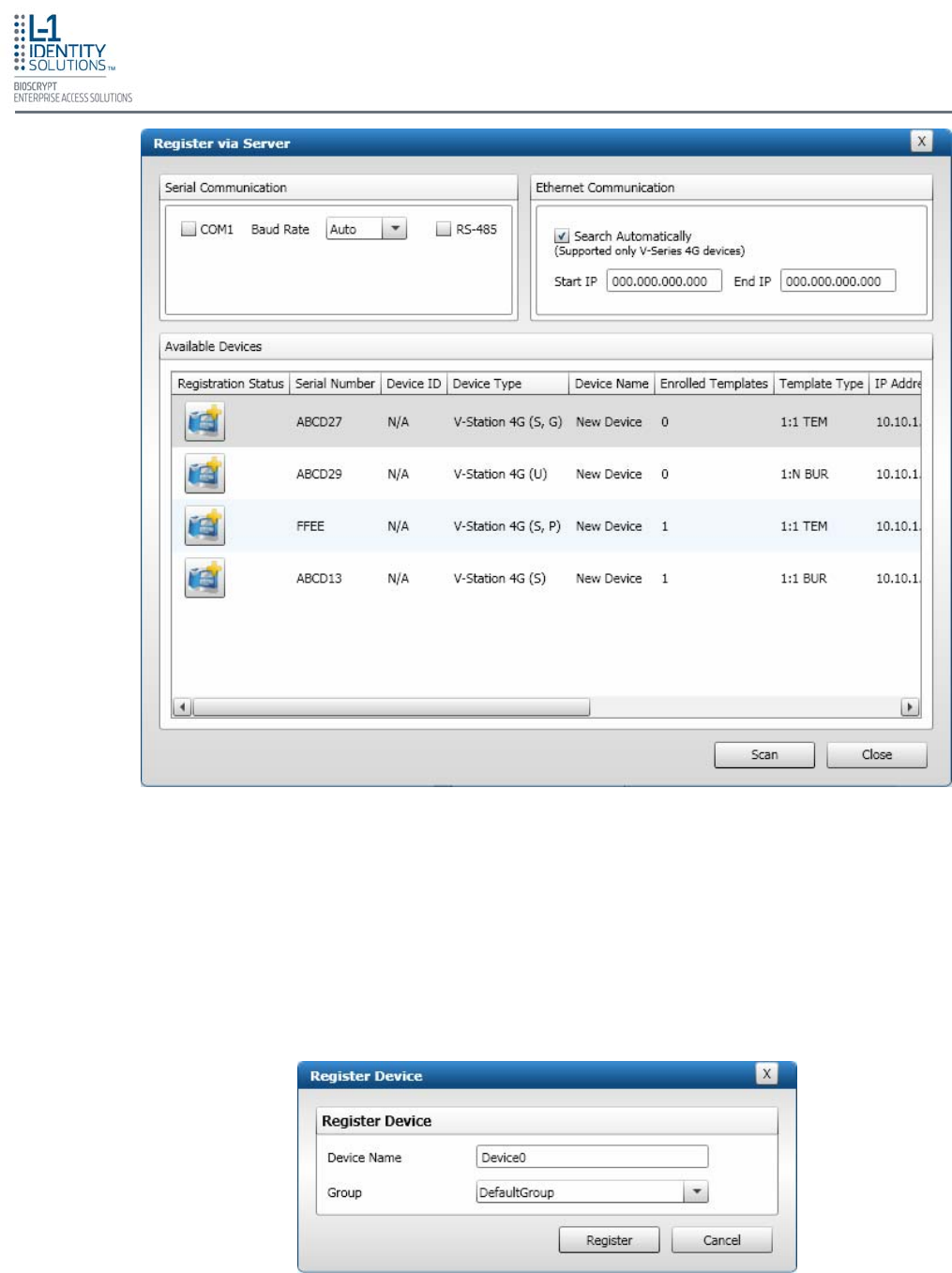
Configure Device
Part No. 430-4G-200-00-000
© 2009, L-1 Identity Solutions Inc. 6-3
4. Select the Search Automatically check box.
5. Click the Scan button. SecureAdmin scans the network for connected devices and lists the
results. Devices with "plus" signs in their icon are available to add.
6. In the list, click the icon of the device you want to register. A Register Device dialog box is
displayed (see Figure 6-3).
Figure 6-2: Register via Server Dialog Box
Figure 6-3: Register Device Dialog Box
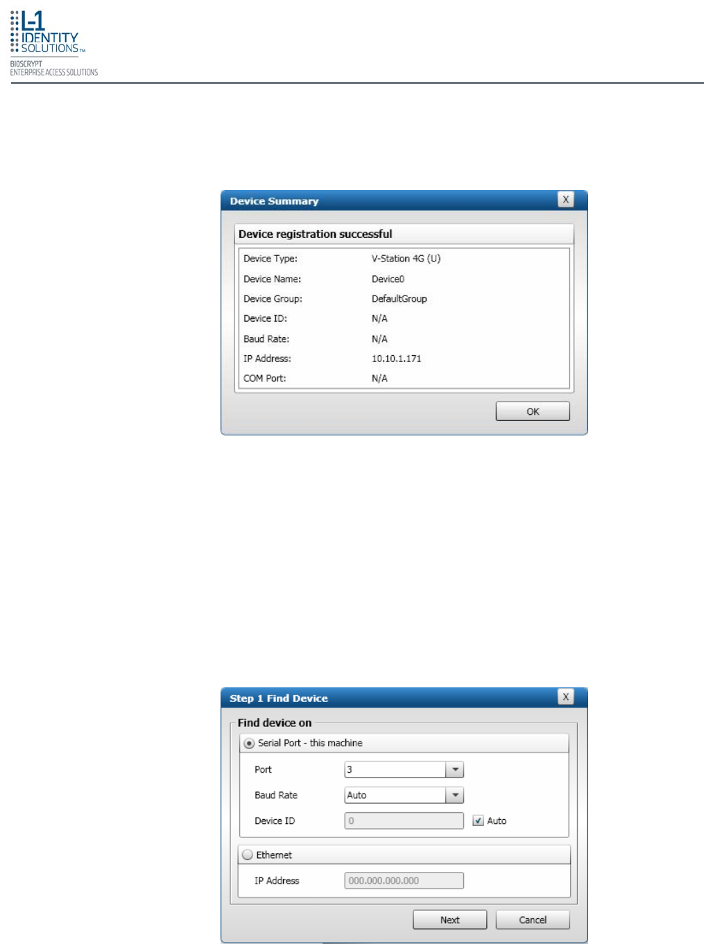
Configure Device
Part No. 430-4G-200-00-000
© 2009, L-1 Identity Solutions Inc. 6-4
7. Enter a Device Name.
8. Select a Group.
9. Click Register. A Device Summary is displayed (see Figure 6-4).
10. Click OK.
11. Click Close. The device is registered.
To register a device via a client:
1. Launch SecureAdmin.
2. Double-click the Network tab. Three buttons are displayed.
3. Click the Register via client button. The Step 1 Find Device dialog box is displayed (see
Figure 6-5).
Figure 6-4: Device Summary Dialog Box
Figure 6-5: Step 1 Find Device Dialog Box
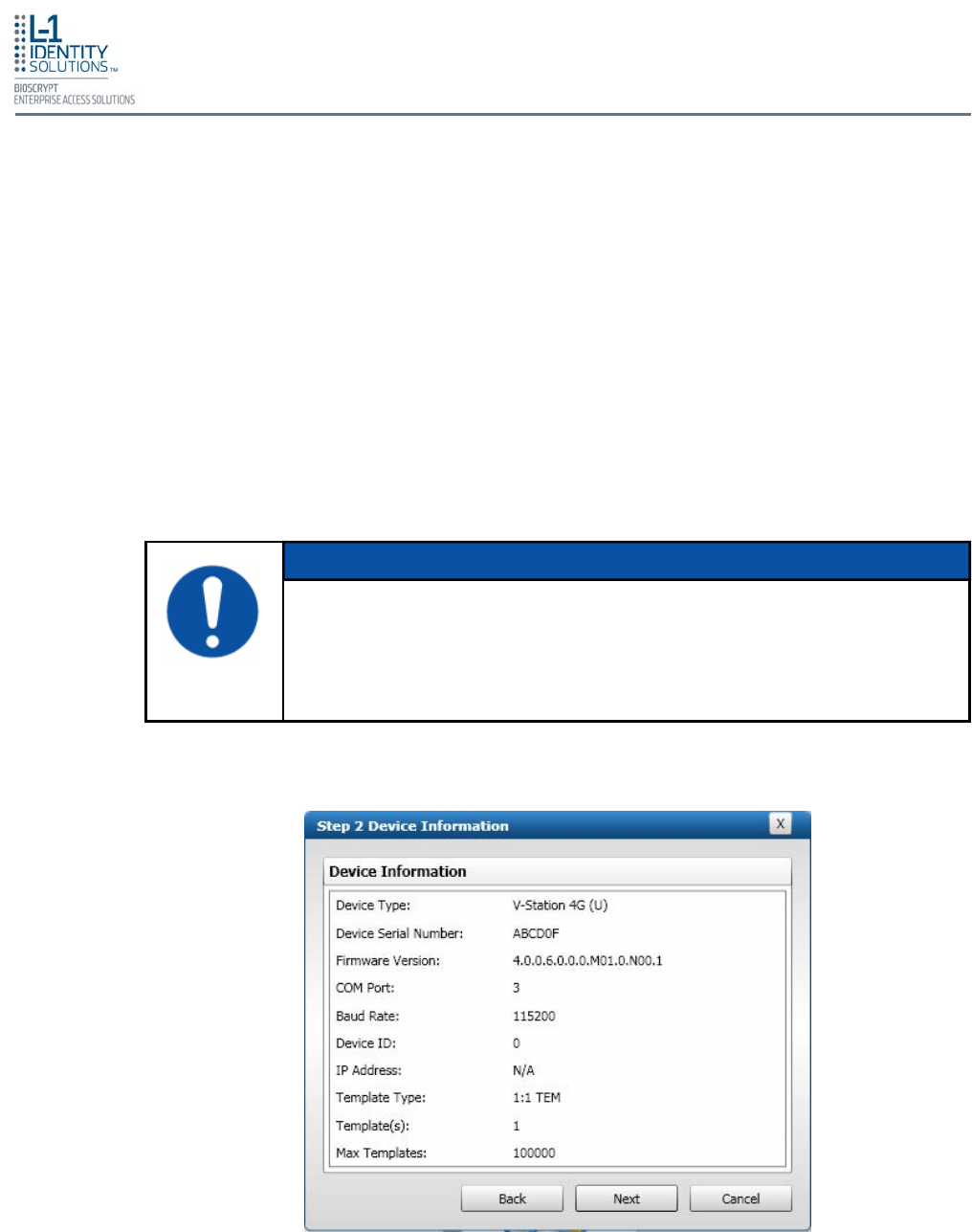
Configure Device
Part No. 430-4G-200-00-000
© 2009, L-1 Identity Solutions Inc. 6-5
4. Select either Serial Port - this machine or Ethernet radio button.
5. Enter the appropriate connection details.
If you are connecting via USB/RS-232:
Enter the appropriate Port Number (to determine the correct port number, look in the Win-
dows Device Manager for a "Gadget Serial" entry under the "Ports (COM & LPT)" heading),
Baud Rate, and Device ID.
If you are connecting via RS-485:
Enter the appropriate Port Number (to determine the correct port number, look in the Win-
dows Device Manager for your RS-485 entry under the "Ports (COM & LPT)" heading),
Baud Rate, and Device ID.
If you are connecting via Ethernet:
Enter the network IP Address of the device you want to connect to.
6. Click Next. The Step 2 Device Information dialog box is displayed (see Figure 6-6).
6. Click Next. The Step 3 Server Communication Parameter dialog box is displayed (see
Figure 6-7 on the next page).
The first time a V-Station 4G or V-Flex 4G device is connected to the com-
puter via the USB/RS-232 interface, the Windows Found New Hardware
Wizard might start. As all required device drivers are installed when Secu-
reAdmin is installed, simply follow the prompts, accepting the default choices
when possible, to install the device.
NOTICE
Figure 6-6: Step 2 Device Information Dialog Box
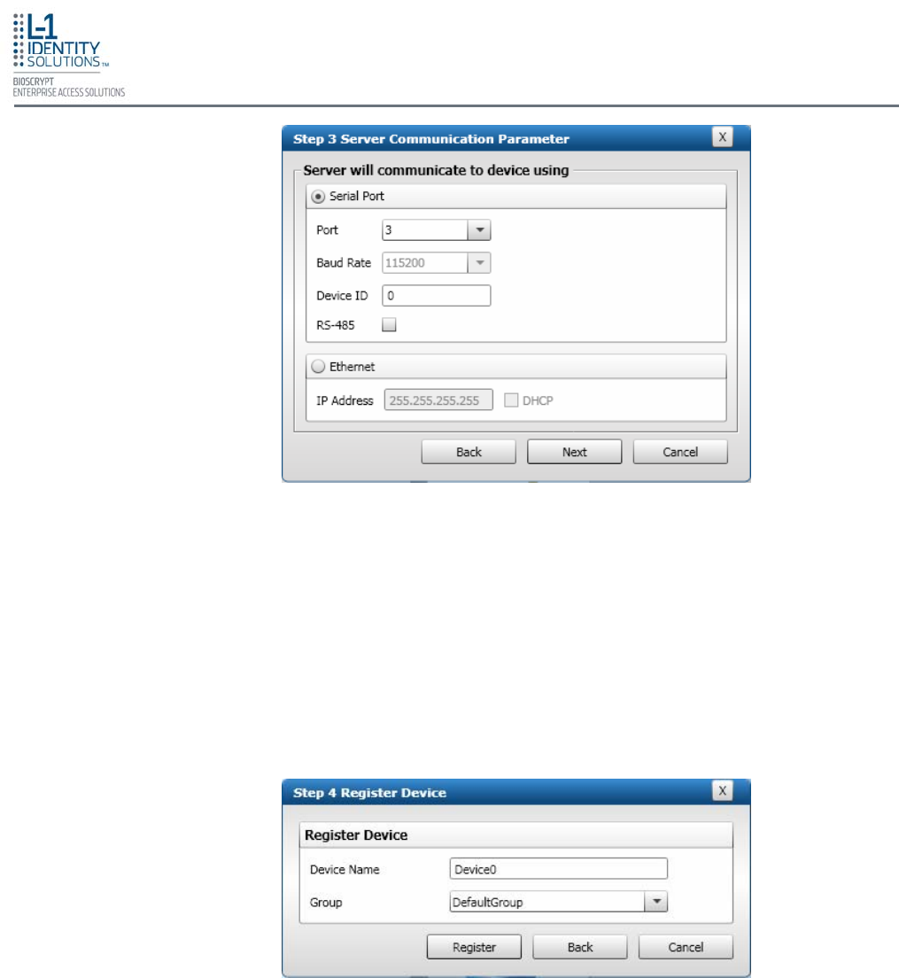
Configure Device
Part No. 430-4G-200-00-000
© 2009, L-1 Identity Solutions Inc. 6-6
7. Select the radio button that corresponds how the server will connect to the device, either by
Serial Port or by Ethernet.
8. If connecting via RS-232 or RS-485, enter the appropriate Port, Baud Rate, and Device ID
(if using RS-485, also select the RS-485 check box). If connecting via Ethernet, enter the
network IP Address of the device (select the DHCP check box if dynamic IP addressing is
used).
9. Click Next. The Step 4 Register Device dialog box is displayed (see Figure 6-8).
10. Enter a Device Name.
11. Select the Group the device will belong to from the drop-down menu.
12. Click Register. The Device Summary dialog box is displayed (see Figure 6-9 on the next
page).
Figure 6-7: Step 3 Server Communication Parameter Dialog Box
Figure 6-8: Step 4 Register Device Dialog Box
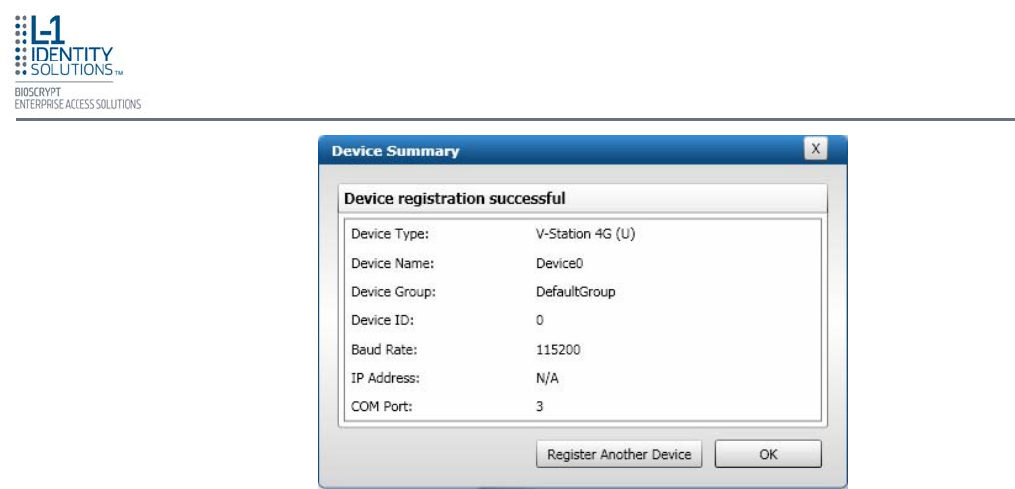
Configure Device
Part No. 430-4G-200-00-000
© 2009, L-1 Identity Solutions Inc. 6-7
13. Click OK.
Figure 6-9: Device Summary Dialog Box

Configure Device
Part No. 430-4G-200-00-000
© 2009, L-1 Identity Solutions Inc. 6-8
This page left blank intentionally

Maintenance and Cleaning
Part No. 430-4G-200-00-000
© 2009, L-1 Identity Solutions Inc. 7-1
7. Maintenance and Cleaning ................................................................................................................. 7-2
7.1. Field Maintenance............................................................................................................... 7-2
7.1.1. Disarming the Tamper Protection ...................................................................... 7-2
7.1.2. Replacing the Sensor ......................................................................................... 7-3
7.1.2.1. V-Flex 4G ............................................................................................ 7-3
7.1.2.2. V-Station 4G ........................................................................................ 7-5
7.1.3. Calibrating the Sensor ....................................................................................... 7-7
7.2. Cleaning ............................................................................................................................. 7-9
This chapter explains how to replace and calibrate the fingerprint sensor module, and how to clean the
device sensor.
Chapter Index
Chapter 7 - Maintenance and Cleaning
Chapter Overview
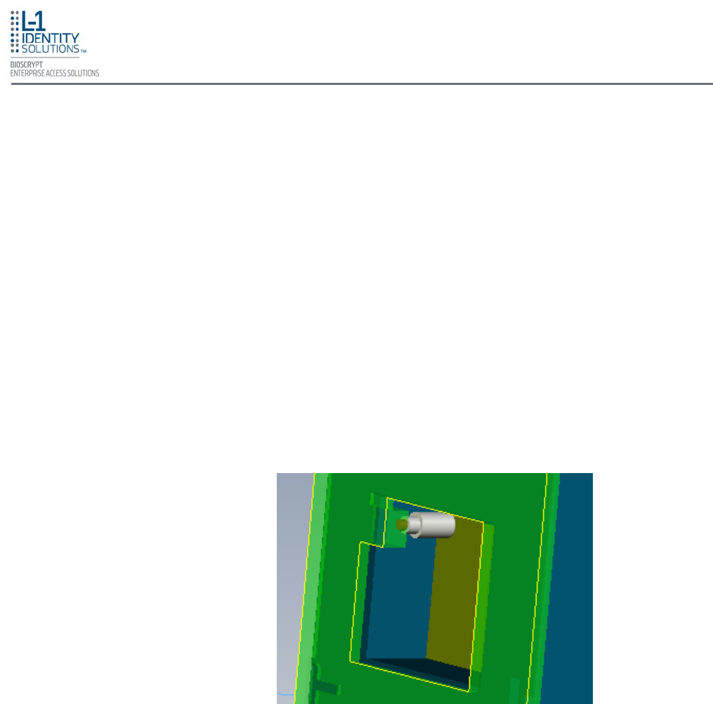
Maintenance and Cleaning
Part No. 430-4G-200-00-000
© 2009, L-1 Identity Solutions Inc. 7-2
7. MAINTENANCE AND CLEANING
The V-Station 4G and V-Flex 4G devices require very little in the way of daily maintenance except for
occasional cleaning and disinfecting. The V-Station 4G and V-Flex 4G devices feature field-replaceable
sensors.
V-Station 4G and V-Flex 4G fingerprint sensors can be replaced quickly and easily in the field.
The following sections explain in detail the steps required to replace a sensor.
7.1. FIELD MAINTENANCE
7.1.1. DISARMING THE TAMPER PROTECTION
The Tamper Switch is a momentary push-button switch on the back of the device within
the I/O cable interface pocket (see Figure 7-1).
The tamper protection feature allows the device to sound an audio alert, flash LEDs,
send a pre-defined Wiegand string to the control panel, or disable biometrics if the tam-
per switch is triggered.
With the wall mounting plate mounted and the device secured to the mounting plate, the
tamper switch is depressed, closing the electrical circuit. When the device is removed
from the wall by removing the security screws or in the event that the device is removed
from the wall by force, the tamper switch opens.
To access the tamper-protection setting on the V-Station 4G device using the keypad:
1. Enter the Admin menu on the device by pressing the Left arrow and Enter keys
simultaneously.
2. Key in the Admin password (default is "0000") and press OK.
Figure 7-1: Tamper Switch Location
Maintenance and Cleaning
Part No. 430-4G-200-00-000
© 2009, L-1 Identity Solutions Inc. 7-3
7.1.2.1. V-FLEX 4G
7.1.2. REPLACING THE SENSOR
The sensors can only be replaced with the same type as previously used. L-1
EAS does not support changing the type of sensor. Different types of sensors
are not interchangeable, and the device will fail to operate.
WARNING
3. Select the System icon and press OK.
4. Select Device Settings and press OK.
5. Select SDC/Tamper Settings and press OK.
6. Select Tamper Settings and press OK.
If the alarm has sounded, select Clear and Re-enable.
The Tamper protection setting is set to disabled by default.
To replace the sensor module in a V-Flex 4G device, follow these steps:
1. Remove the security screw and slide the V-Flex 4G device up until the
hooks are free from the wall-mounting plate.
2. Remove two Philips screws, as shown in Figure 7-2 (on the next page).
3. Gently slide the sensor back plate, sensor mask, and sensor out of the V-
Flex 4G device. Be careful not to damage any internal wiring.
4. Disconnect the sensor module wiring harness from the internal device
connector. It might be necessary to rock the connector back and forth to
work it out. Do not pull with excessive force as you might damage the
mating connector.
• Power to the device MUST BE DISCONNECTED prior to servicing.
• If the device is secured to the wall please be sure to follow the Disable
Tamper settings prior to the removal of the device from the wall.
• ESD protective handling procedures must be followed before any service
is applied to the device.
NOTICE
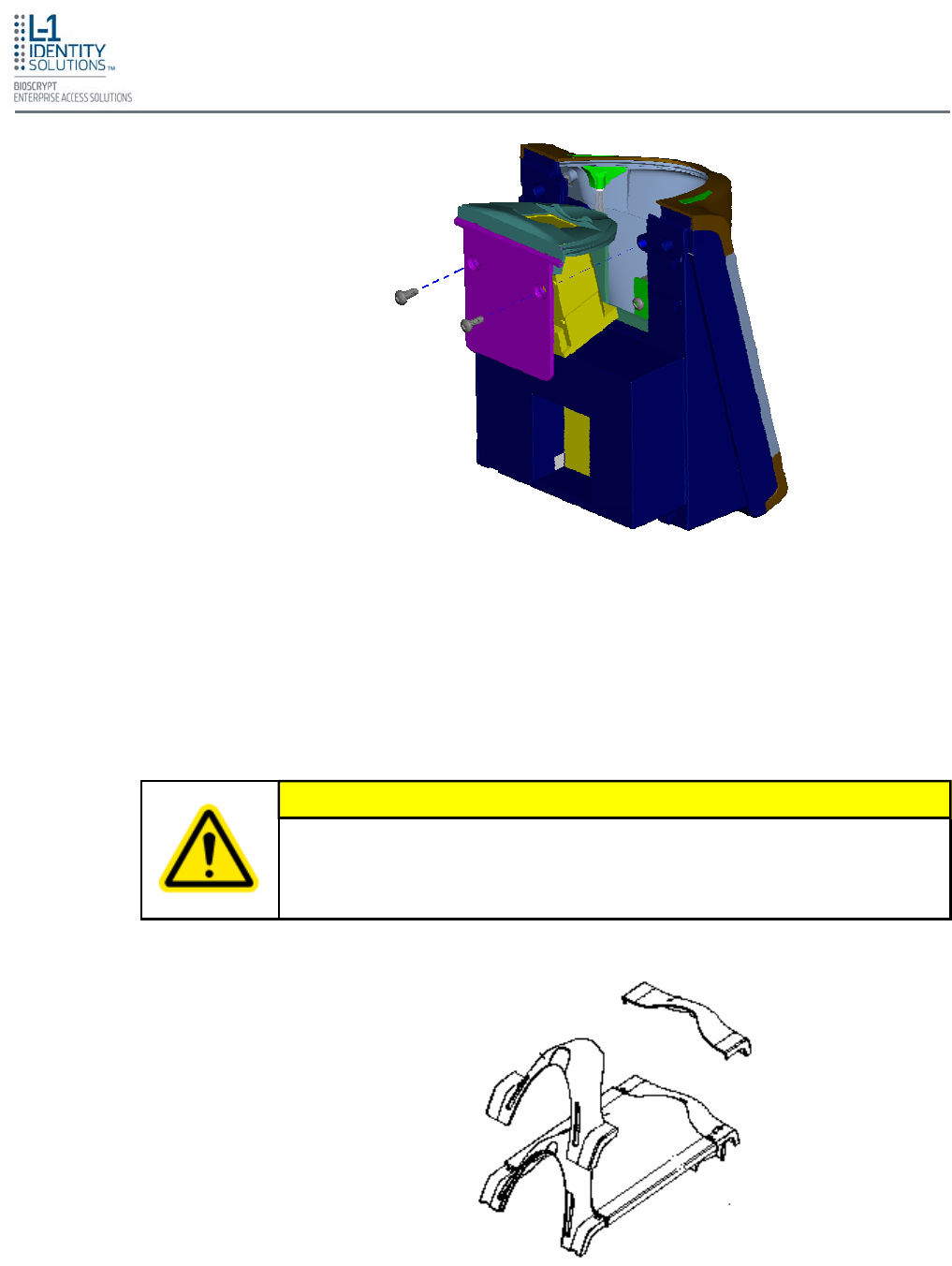
Maintenance and Cleaning
Part No. 430-4G-200-00-000
© 2009, L-1 Identity Solutions Inc. 7-4
The parts shown in Figure 7-3 are assembled at the factory and are not
meant to be removed by the end user. Removing any of these parts will void
the warranty.
CAUTION
5. Disconnect the sensor module wiring harness from the sensor module. Do
not damage the wiring harness as it will be re-used with the new sensor
module.
6. Reassembly is the reverse of disassembly.
Figure 7-3: Non-Removable Parts (V-Flex 4G)
Figure 7-2: Removal of Sensor Module from V-Flex 4G Device
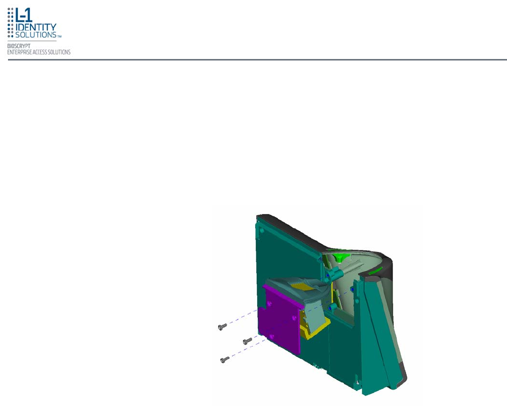
Maintenance and Cleaning
Part No. 430-4G-200-00-000
© 2009, L-1 Identity Solutions Inc. 7-5
7.1.2.2. V-STATION 4G
To replace the sensor module in a V-Station 4G device, follow these steps:
1. Remove the security screw.
2. Tilt the device at an angle approximately 90 degrees to the wall.
3. Remove the three Philips screws, as shown in Figure 7-4.
Figure 7-4: Removal of Sensor Module from V-Station 4G Device
4. Gently slide the sensor back plate, sensor mask, and sensor out of the V-
Station 4G device. Be careful not to damage any internal wiring.
5. Disconnect the sensor module wiring harness from the internal device
connector. It might be necessary to rock the connector back and forth to
work it out. Do not pull with excessive force as you might damage the
mating connector.
6. Disconnect the sensor module wiring harness from the sensor module. Do
not damage the wiring harness as it will be re-used with the new sensor
module.
7. Reassembly is the reverse of disassembly.
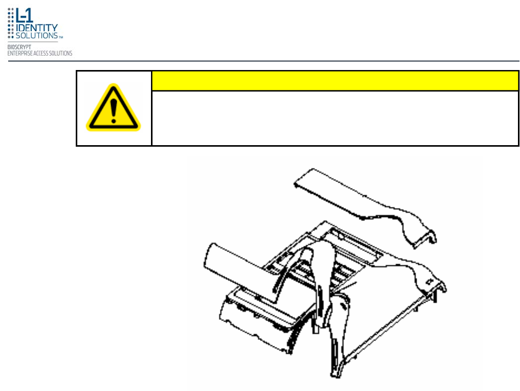
Maintenance and Cleaning
Part No. 430-4G-200-00-000
© 2009, L-1 Identity Solutions Inc. 7-6
The parts shown in Figure 7-5 are assembled at the factory and are not
meant to be removed by the end user. Removing any of these parts will void
the warranty.
CAUTION
Figure 7-5: Non-Removable Parts (V-Station 4G)
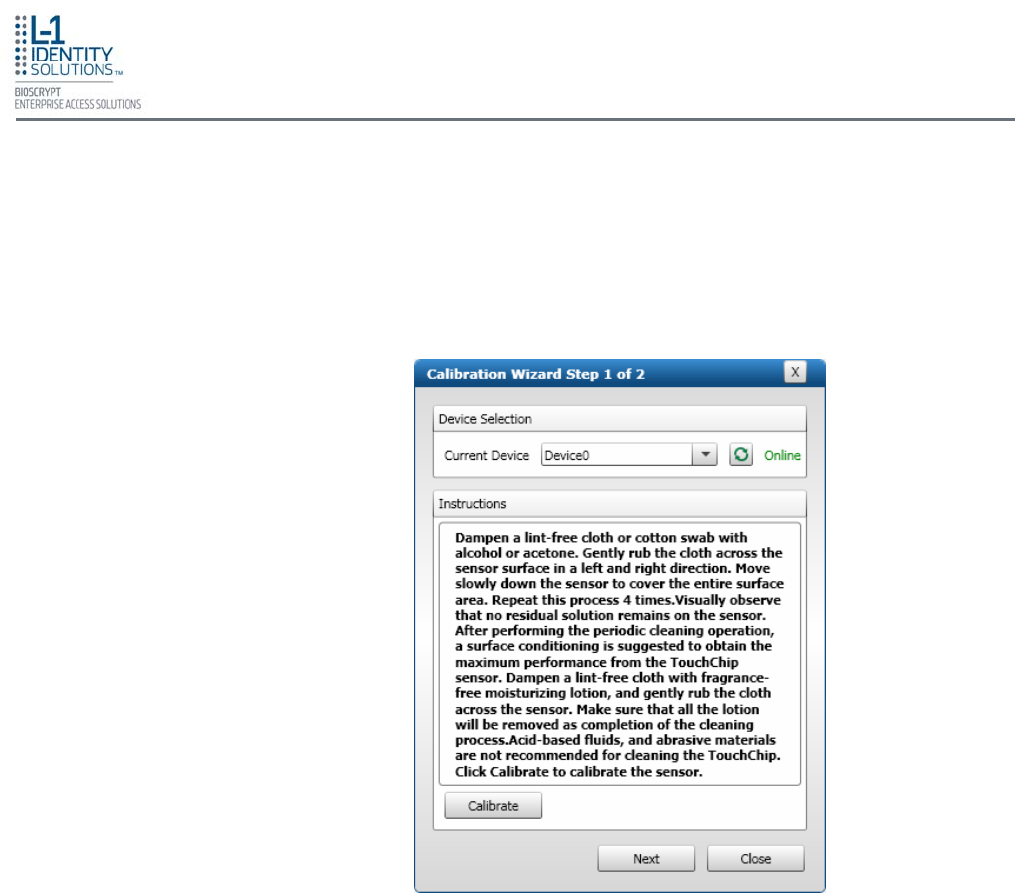
Maintenance and Cleaning
Part No. 430-4G-200-00-000
© 2009, L-1 Identity Solutions Inc. 7-7
7.1.3. CALIBRATING THE SENSOR
After a device sensor is replaced, it must be calibrated before it can be used.
To calibrate a device:
1. Select Sensor Calibration in the Tools drop-down menu. The Calibration Wizard
dialog box is displayed (see Figure 6-10).
Figure 7-6: Calibration Wizard Step 1 of 2 Dialog Box
2. Select the device you want to calibrate in the Current Device menu.
3. Click Calibrate. Wait as the device sensor is calibrated.
4. Click Next. The Calibration Wizard Step 2 dialog box is displayed (see Figure 6-11
on the next page).
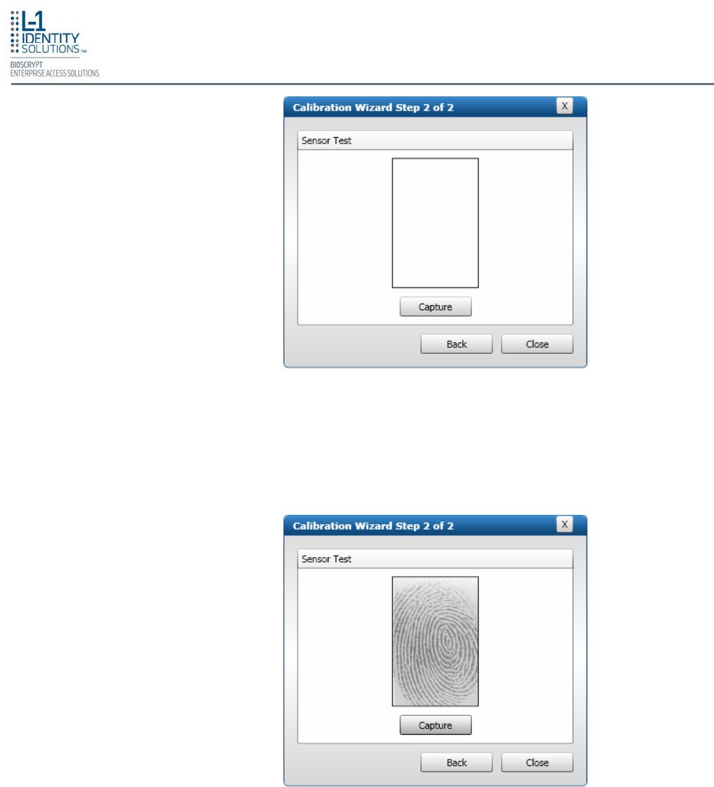
Maintenance and Cleaning
Part No. 430-4G-200-00-000
© 2009, L-1 Identity Solutions Inc.
5. Click Capture.
6. Place a finger on the sensor, hold it, and remove it as directed by the on-screen
prompts. The capture results are displayed (see Figure 6-12).
7. Click Close. The device sensor is now fully calibrated and ready to use.
Figure 7-7: Calibration Wizard Step 2 of 2 Dialog Box
Figure 7-8: Calibration Wizard Capture Results Dialog Box
7-8
Maintenance and Cleaning
Part No. 430-4G-200-00-000
© 2009, L-1 Identity Solutions Inc. 7-9
Sensors become soiled with residue, oils, or other contaminants due to contact with fingers and
exposure to the elements. The sensor surface should be cleaned periodically for performance,
aesthetic, and hygienic reasons. Care must be taken when cleaning the sensor to prevent dam-
aging the sensor surface or surrounding components.
To clean the fingerprint sensor in a V-Station 4G or V-Flex 4G device:
1. Remove electrical power from the device.
2. Moisten (do not saturate) a clean cotton swab or a lint-free cloth with rubbing (Isopropyl)
alcohol.
3. Rub the sensor surface with the moistened cotton swab or lint-free cloth. Do not allow the
cleaning product to drip onto any electronic components near the sensor.
4. Rub the sensor with a clean dry cotton swab or lint-free cloth to remove any traces of clean-
ing product.
5. Reconnect power to the device.
7.2. CLEANING
Do not use chlorine-based cleaners, such as bleach, or chlorine-based bath-
room or mildew cleaners. Chlorine-based cleaners will not adversely affect
the fingerprint sensor, but they could damage the electronic circuitry sur-
rounding the fingerprint sensor.
Do not use solvents such as acetone, methyl ethyl ketone, lacquer thinner,
etc. Solvents will not adversely affect the sensor, but they are likely to dam-
age the reader housing or other peripheral components.
CAUTION
Disposable ESD-safe wipes, such as ACL Staticide wipes, can be used to
disinfect the sensor and buttons on a daily (or even more frequent) basis. Be
aware that some wipes might not offer the same cleaning power as the prod-
ucts mentioned above and thus should not be relied upon to thoroughly re-
move all residue. Use of wipes does, however, helps keep sensor and button
surfaces hygienic and makes an excellent complement to periodic cleaning.
NOTICE
Never use products such as abrasive cleaning powders, steel wool, scouring
pads, or fine sandpaper to clean the sensor surface. These types of cleaning
products will damage the sensor surface.
WARNING

Maintenance and Cleaning
Part No. 430-4G-200-00-000
© 2009, L-1 Identity Solutions Inc. 7-8
This page left blank intentionally

Troubleshooting
Part No. 430-4G-200-00-000
© 2009, L-1 Identity Solutions Inc. 8-1
8. Troubleshooting .................................................................................................................................. 8-2
8.1. Installation Error Messages ................................................................................................ 8-2
8.1.1. Error 1303 - Insufficient Privileges ..................................................................... 8-2
8.1.2. Error 27552 - Error Creating Database .............................................................. 8-3
8.1.3. Invalid Password ................................................................................................ 8-4
8.1.4. Error 27502 - User Not Associated with Trusted SQL Server ........................... 8-5
8.1.5. Error 27502 - SQL Server Does Not Exist ......................................................... 8-6
8.1.6. Insufficient System Memory ............................................................................... 8-7
8.1.7. Out of Disk Space .............................................................................................. 8-8
This chapter information about any error messages that might be experienced during the installation
process.
Chapter Index
Chapter 8 - Troubleshooting
Chapter Overview
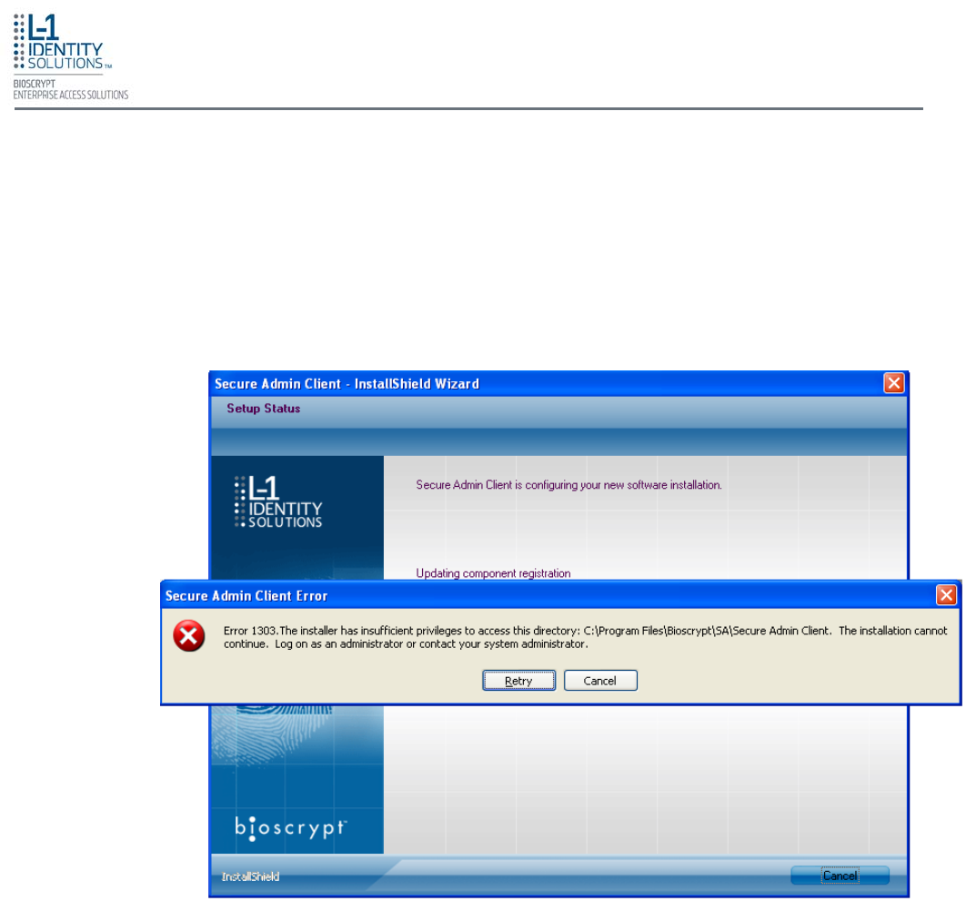
Troubleshooting
Part No. 430-4G-200-00-000
© 2009, L-1 Identity Solutions Inc. 8-2
8. TROUBLESHOOTING
These error messages might occur during the SecureAdmin installation process.
8.1. INSTALLATION ERROR MESSAGES
8.1.1. ERROR 1303 - INSUFFICIENT PRIVILEGES
This error can occur during SecureAdmin Client installation at the last step (right before
“Finish”). If it occurs, it means that the user does not have sufficient rights to install
software on the computer.
Log off and log on either as a Administrator or another user that has sufficient privileges
to install software and perform the setup process again.
Figure 8-1: Error 1303
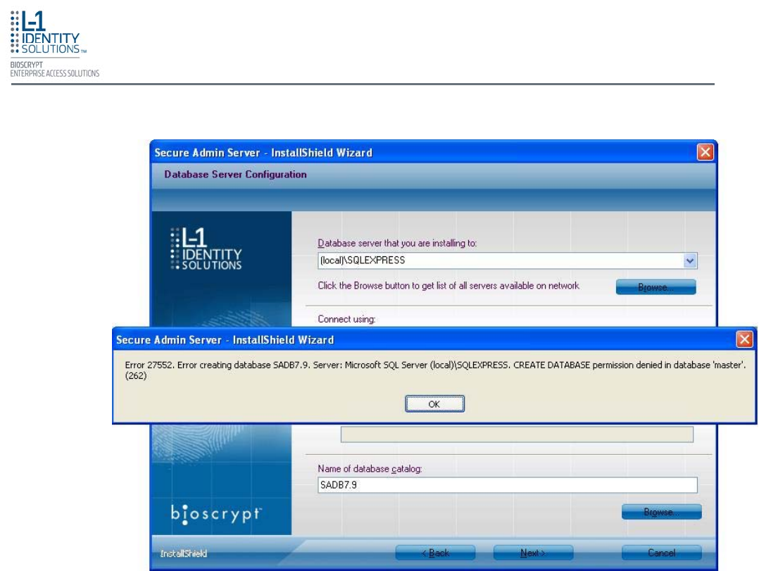
Troubleshooting
Part No. 430-4G-200-00-000
© 2009, L-1 Identity Solutions Inc. 8-3
8.1.2. ERROR 27552 - ERROR CREATING DATABASE
This error can occur during SecureAdmin Server installation process. If it occurs, it
means that the user does not have sufficient privileges to access a specific SQL
database.
Contact your IT department to ensure that your privileges are correct for the specified
database.
Figure 8-2: Error 27552
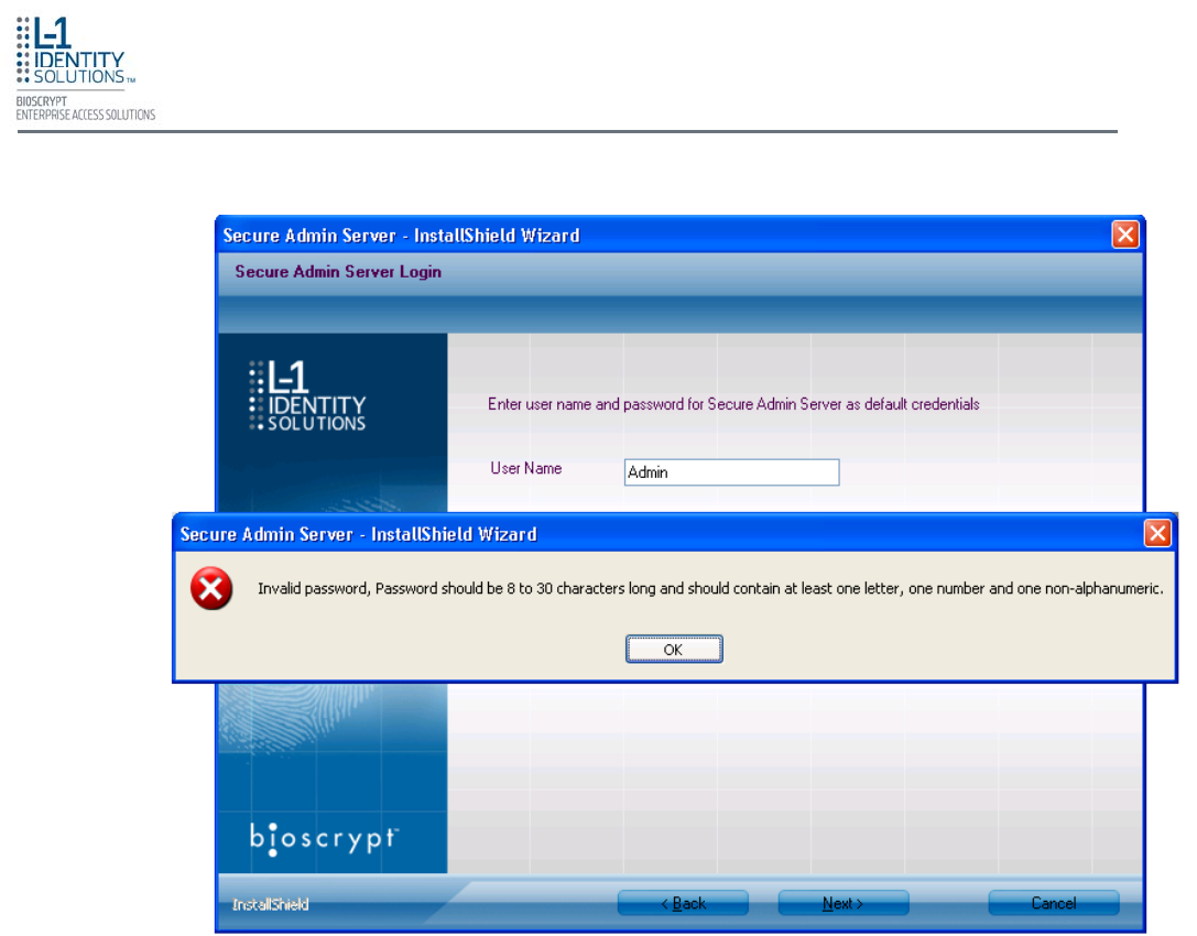
Troubleshooting
Part No. 430-4G-200-00-000
© 2009, L-1 Identity Solutions Inc. 8-4
8.1.3. INVALID PASSWORD
This error can occur during SecureAdmin Server installation process on the User
configuration screen (after the database configuration screen).
If it occurs, it means that the password provided is not strong enough. Click OK, and re-
enter a password that is considered more secure. The password should be between 8
and 30 characters long and contain at least one capital letter, one number, and one
non-alphanumeric character.
Figure 8-3: Invalid Password
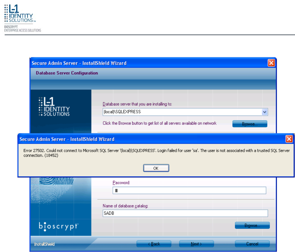
Troubleshooting
Part No. 430-4G-200-00-000
© 2009, L-1 Identity Solutions Inc. 8-5
8.1.4. ERROR 27502 - USER NOT ASSOCIATED WITH TRUSTED SQL SERVER
This error can occur during the SecureAdmin Server installation process. If it occurs, it
means that the InstallShield Wizard could not access the specified SQL database.
Check your user name and password or contact your IT department to ensure that your
user name is associated with the specified SQL database.
Figure 8-4: Error 27502 - User Not Associated
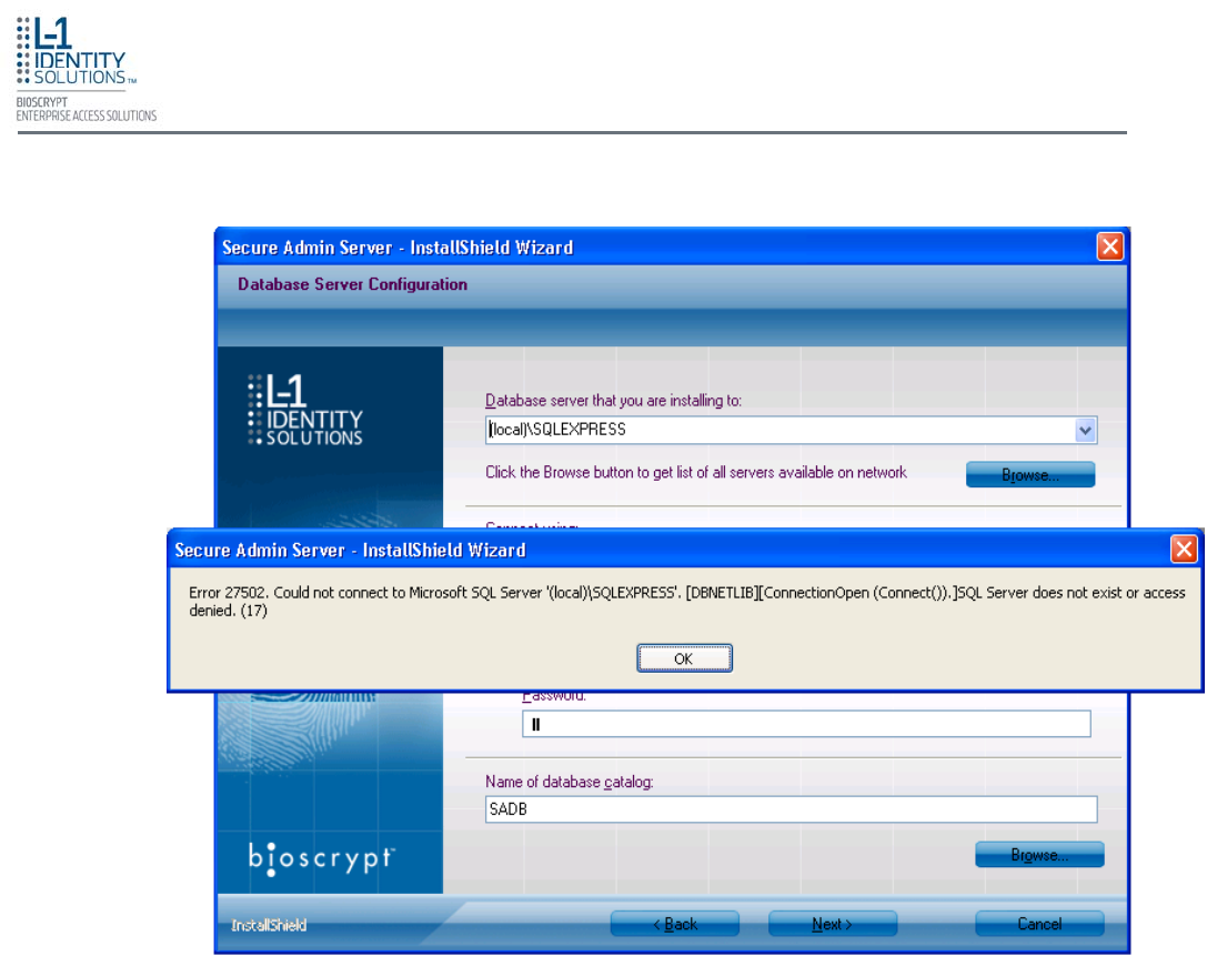
Troubleshooting
Part No. 430-4G-200-00-000
© 2009, L-1 Identity Solutions Inc. 8-6
8.1.5. ERROR 27502 - SQL SERVER DOES NOT EXIST
This error can occur during the SecureAdmin Server installation process (at the time of
database configuration, after the database selection screen). If it occurs, it means that
the InstallShield Wizard could not connect to the specified SQL database because it
does not exist or because the user is not authorized to access that database
Check your user name and password or contact your IT department to ensure that your
user name is authorized to access the specified SQL database.
Figure 8-5: Error 27502 - Server Does Not Exist
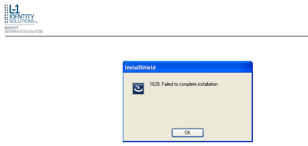
Troubleshooting
Part No. 430-4G-200-00-000
© 2009, L-1 Identity Solutions Inc. 8-7
8.1.6. INSUFFICIENT SYSTEM MEMORY
This error can occur during the SecureAdmin Server installation process at the first
screen after selecting server installation from the options screen.
If it occurs, it means that the computer you are trying to install SecureAdmin Server on
does not have sufficient system memory. Install more memory or install on a different
machine.
Figure 8-6: Insufficient System Memory
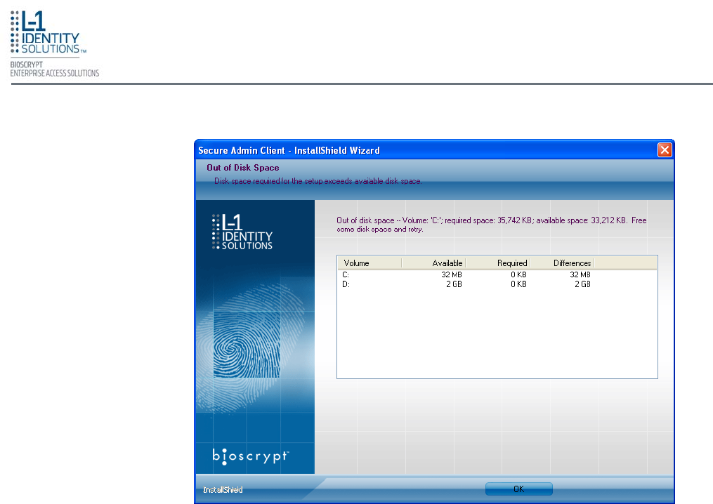
Troubleshooting
Part No. 430-4G-200-00-000
© 2009, L-1 Identity Solutions Inc. 8-8
This error can occur during the SecureAdmin Client installation process when Secu-
reAdmin starts to configure components, after the fingerprint feedback options selection.
If it occurs, it means that the computer hard drive you are trying to install SecureAdmin
Client on does not have sufficient hard drive space. Install a larger hard drive or install
to a another hard drive that has sufficient disk space.
8.1.7. OUT OF DISK SPACE
Figure 8-7: Out of Disk Space

Contact Information
Part No. 430-4G-200-00-000
© 2009, L-1 Identity Solutions Inc. 9-1
CHAPTER 9 - CONTACT INFORMATION
The L-1 Enterprise Access team endeavors to resolve all inquiries from clients with supported products
in a timely fashion. Please visit our webpage for the most up to date information, hours, contacts, and
resources available for resolving your technical needs. Please note that some services are provided un-
der a support contract or warranty only.
Website: http://www.l1id.com/enterpriseaccess/support
North America: Support-EnterpriseAccess@L1ID.com
International: Support-Intl-EnterpriseAccess@L1ID.com
Registering your L-1 products is quick and easy and entitles you to a wide range of benefits
such as notifications of product updates, newsletters, special offers, and invitations to L-1 Enter-
prise Access Division events and training seminars.
Please use the following address to register: http://www.L1ID.com/register4G
9.1. REGISTERING YOUR PRODUCT