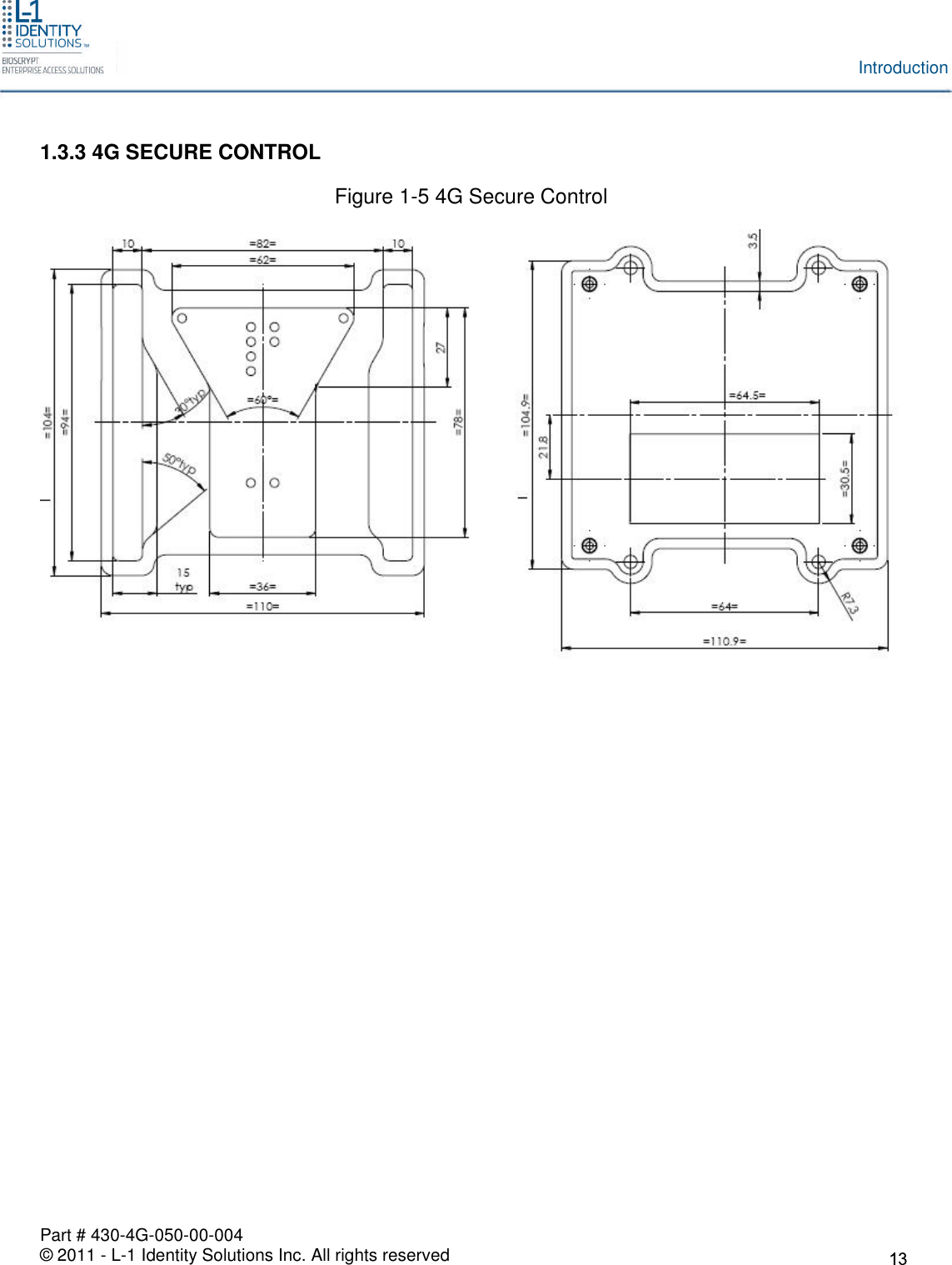
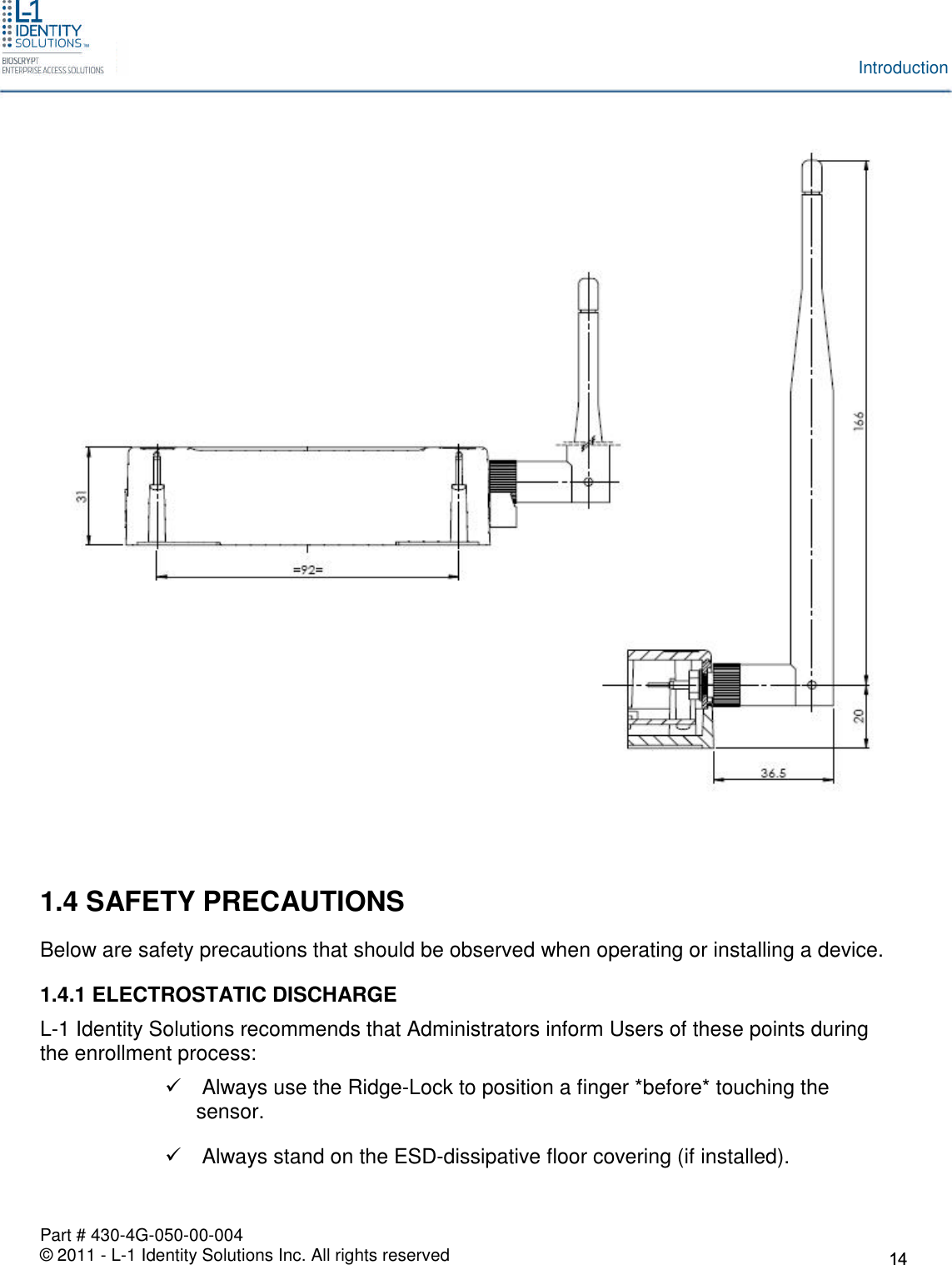
Bioscrypt 4GFXLSP 4G Finger Print and Prox. card Reader User Manual
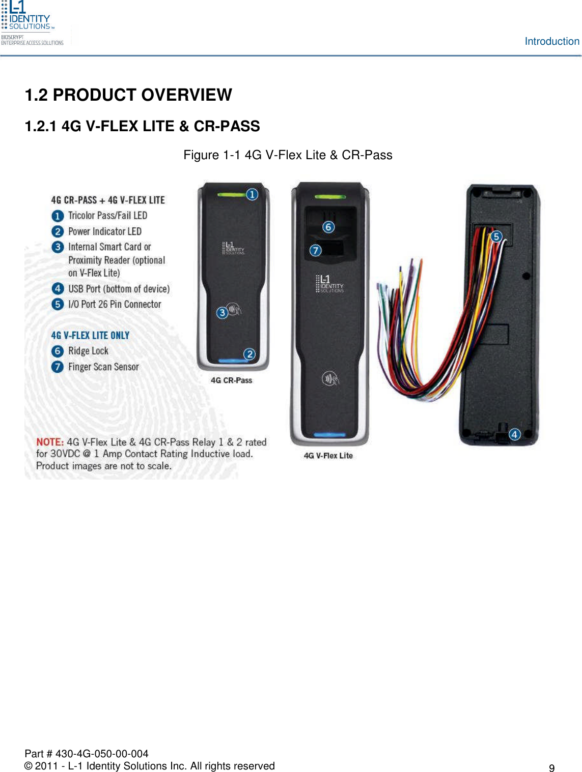
Bioscrypt, Inc. 4G Finger Print and Prox. card Reader Users Manual
UserManual.wiki
>
Bioscrypt
>
4GFXLSP User Manual
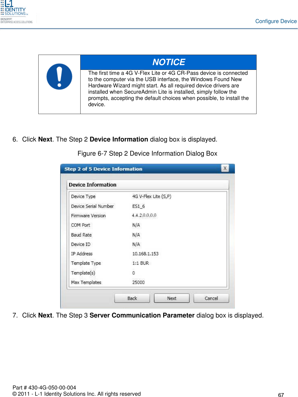
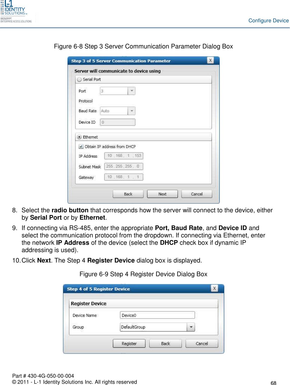
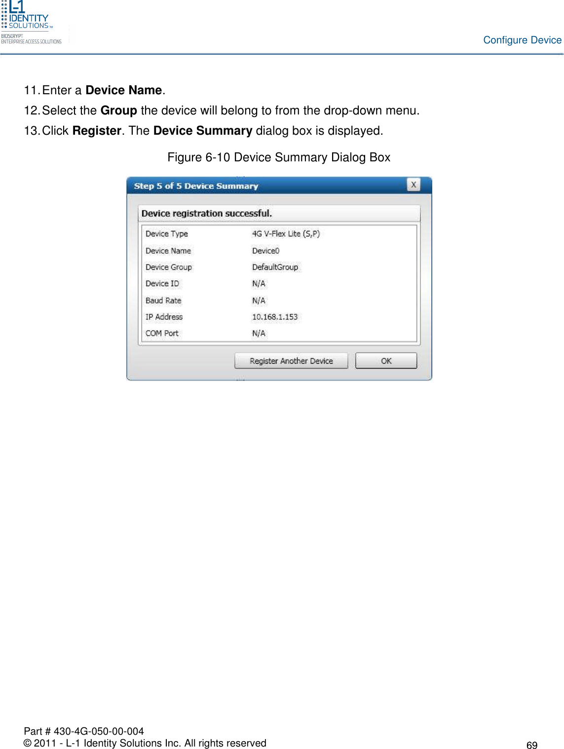
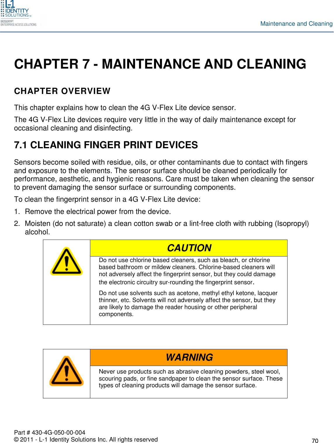
Users Manual
Navigation menu
Upload a User Manual
Namespaces
Wiki Guide
HTML
PDF
Info
Views
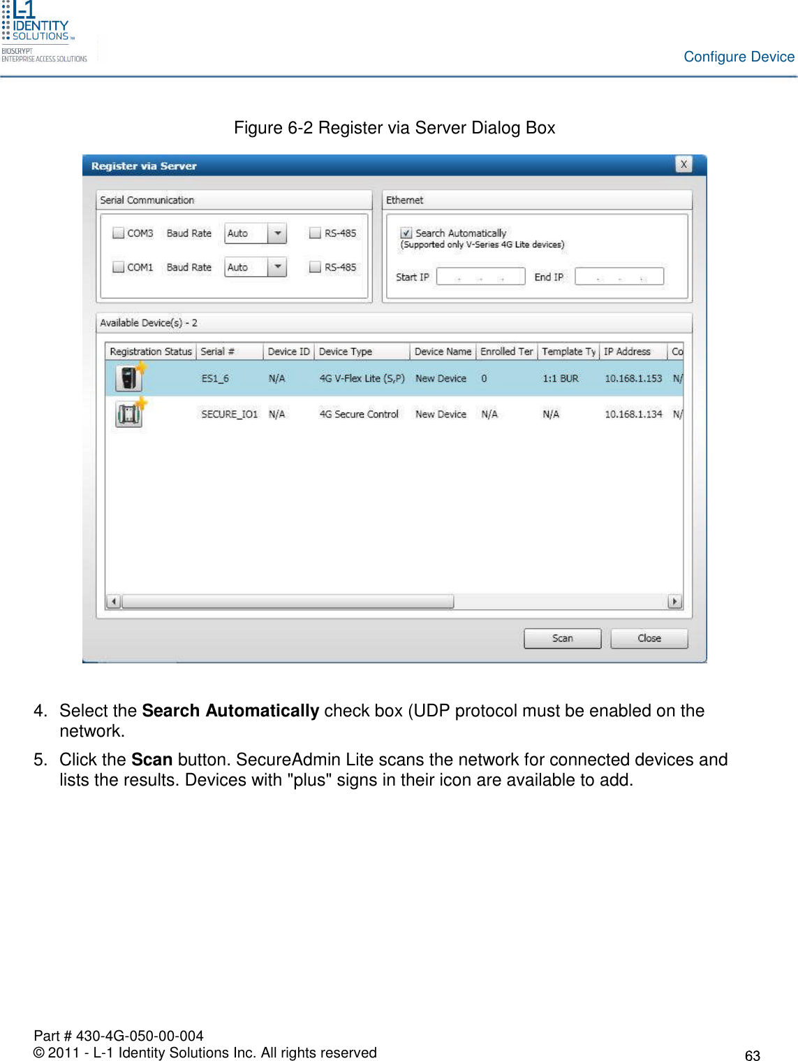
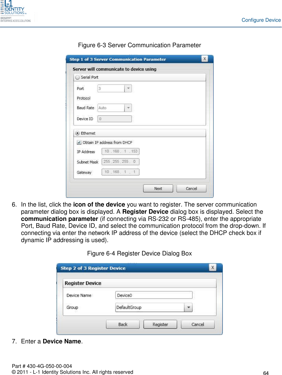
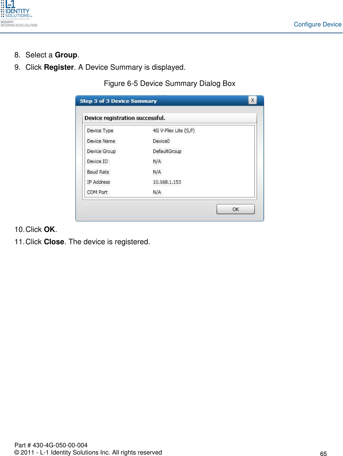
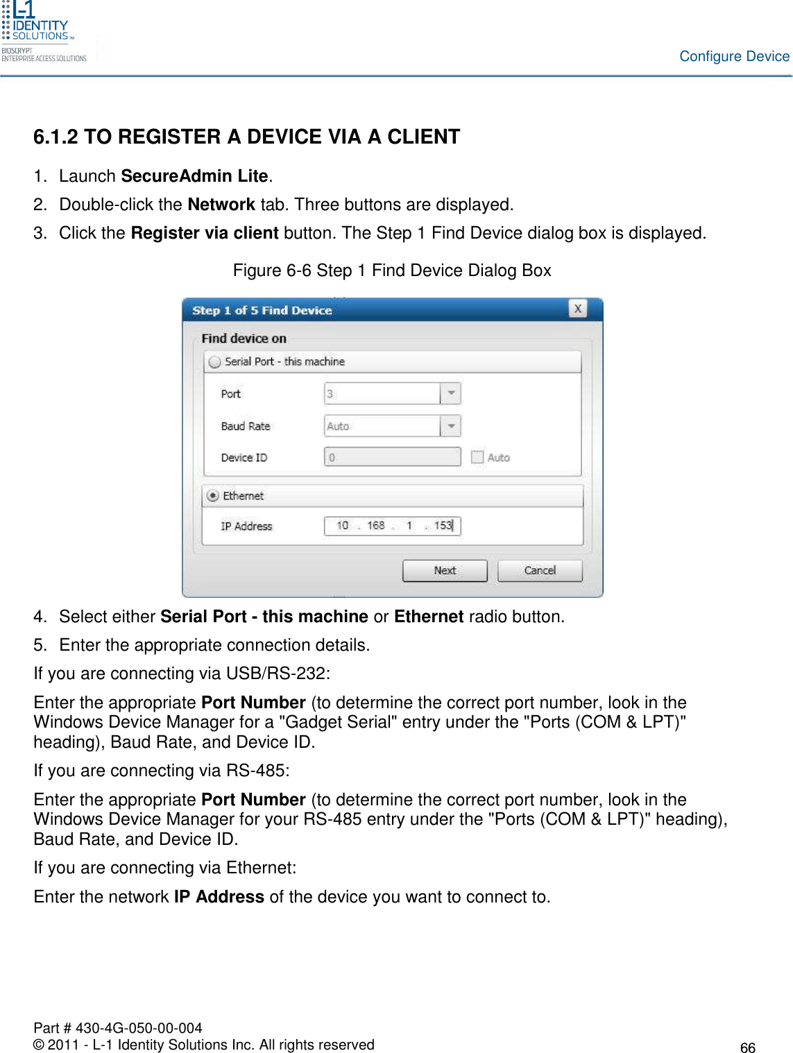
User Manual
Discussion / Help
Navigation