Bioscrypt VSTNAGR V-STATION, A, G, R User Manual Veri Series Installation Guide
Bioscrypt, Inc. V-STATION, A, G, R Veri Series Installation Guide
USERS MANUAL

Document #430-90003-08 © Copyright 2003, Bioscrypt Inc. All rights reserved.
Bioscrypt Inc.
Veri-Series Installation Guide

Page ii
Document #430-90003-08 © Copyright 2003, Bioscrypt Inc. All rights reserved.
Introduction
Bioscrypt is proud to present the Veri-Series line of fingerprint authentication
readers including the V-Prox™, V-Flex™, V-Pass™, V-Smart™, and V-Station™. The
V-Prox™, includes integrated proximity reader and fingerprint verification. The V-
Flex™ allows for upgrading existing installations and using other card technologies.
The V-Pass™ doesn’t require any cards or PINs, and searches through up to 200
fingerprints. The V-Smart™ incorporates contact-less smart card technology so
that a hardwired network is no longer needed. Finally, the V-Station™, the most
flexible of the group, offers convenient administration right from its console and
now supports Ethernet. Select versions provide functionality found in each of the
Veri-Series products, including a proximity or smart card reader, and searching
ability.
Bioscrypt's product offerings leverage over 20 years of experience designing
systems for the US Department of Defense. The company's mission is to bring their
patented fingerprint verification technology, once found only in government or
military applications, to a wide range of commercial applications around the
globe at a reasonable cost.
The V-Prox, V-Flex, V-Smart, and V-Station readers prevent unauthorized access
via loaned, lost or stolen proximity or smart cards by requiring that the fingerprint
of the person seeking entry match the identity of the cardholder. Its ability to verify
fingerprints in the face of adverse conditions like soil and other contaminants
makes the Veri-Series readers useful for factories, plants, construction sites and
similar environments that have previously been unable to implement biometric-
based access solutions.
The V-Pass reader and V-Station searching version capitalize on this same
fundamental algorithm for matching fingerprints but implement it in such a way as
to be able to search through a database of templates to find the matching
template. Therefore, these systems negate the need for cards at all, providing a
convenient yet secure access control solution.
Fingerprint verification has been around for over 100 years, but during that time it
has progressed from an intensive manual operation to an automated computer
operation. The Veri-Series readers represent the state-of-the-art in fingerprint
verification technology. It uses a 100% solid-state design. There are no moving
parts, no optics or lenses, and it provides a variety of communications options.
Page iii
Document #430-90003-08 © Copyright 2003, Bioscrypt Inc. All rights reserved.
Disclaimer
The instructions in this document have been carefully checked for accuracy and
are presumed to be reliable. Bioscrypt, Inc. and its writers assume no responsibility
for inaccuracies and reserve the right to modify and revise this document without
notice.
It is always our goal at Bioscrypt, Inc. to supply accurate and reliable
documentation. If you discover a discrepancy in this document, please e-mail
your comments to support@Bioscrypt.com, or contact Bioscrypt Technical Support
at the telephone number listed below.
No part of this publication may be placed in a retrieval system, transmitted, or
reproduced in any way, including, but not limited to, photograph, photocopy,
computer disk or other record, without prior agreement and written permission
from:
Bioscrypt Inc.
5805 Sepulveda Blvd., Suite 750
Van Nuys, CA 91411
Phone 818.304.7150
Toll Free 888.982.4643
http://www.bioscrypt.com
NOTENOTE: This symbol, found both on the device and throughout this
manual, denotes a caution or warning. When this symbol is
encountered during setup or installation, please be sure to first
carefully read the corresponding section in this manual.

Page iv
Document #430-90003-08 © Copyright 2003, Bioscrypt Inc. All rights reserved.
Bioscrypt One Year Limited Warranty Policy
Bioscrypt warrants to the original consumer purchaser (“Customer”) that new
Bioscrypt products will be free from defects in material and workmanship for one
year from the date the product was shipped from Bioscrypt. For replacement
products the warranty on the replacement unit is the remainder of the warranty
on the original product or ninety (90) days, whichever is longer. The Customer is
responsible for making any claims for shipment damage (evident or concealed)
with the freight carrier. Bioscrypt must be notified within thirty days of shipment of
incorrect materials.
If a defect is discovered, Bioscrypt's sole obligation shall be to repair or replace
the Bioscrypt product(s) at its sole discretion at no charge, provided it is returned
to Bioscrypt during the warranty period and is shipped freight and insurance
prepaid. Merchandise must be properly packaged to prevent damage during
shipping. Before returning a Bioscrypt product, contact Bioscrypt Technical
Service to obtain a Return Material Authorization (RMA) number. No product may
be returned whether in warranty or out of warranty without first obtaining
approval from Bioscrypt. The model number, invoice number, and serial number
may be required for warranty service.
This warranty shall not apply to any product or any part of a product, which in the
judgment of Bioscrypt, has been subjected to misuse, negligence, alteration,
accident, improper maintenance, or damage by excessive physical or electrical
stresses. Tampering, such as opening the housing of a biometric reader or
replacing parts will void this warranty. The warranty is void if the serial number of
the Bioscrypt product has been defaced, altered, or removed or if the product
has been modified. Repair and replacement parts will be furnished on an
exchange basis and may be either reconditioned or new. All replaced parts or
products become the property of Bioscrypt. This warranty may also be voided for
failure to comply with Bioscrypt’s return policy.
The warranty is not applicable to:
• Abnormal wear and tear
• Damage caused during installation
• Damage caused by the equipment or system with which the biometric reader
is used
• Damage caused by modification or repairs not made or authorized by
Bioscrypt
• Damage caused by improper packaging

Page v
Document #430-90003-08 © Copyright 2003, Bioscrypt Inc. All rights reserved.
• Damage caused by lack of ESD protection
• Merchandise that is determined to be stolen
The newest Bioscrypt Veri-Series products are designed to be weather resistant but
no sensor technology exists today that can work in all weather environments. If a
Bioscrypt Veri-Series product is not used in a completely indoor environment, then
a protective cover is required to shield the sensor from moisture, dust, and other
contaminants that will degrade sensor operation and void the product warranty.
This warranty is exclusive and in lieu of all others, whether oral or written, expressed
or implied. Bioscrypt specifically disclaims any and all implied warranties,
including without limitation, warranties of merchantability and fitness for any
particular purpose. No Bioscrypt dealer, agent, or employee is authorized to make
any modification, extension or addition to this warranty.

Page vi
Document #430-90003-08 © Copyright 2003, Bioscrypt Inc. All rights reserved.
Notices
The Veri-Series line of products have been tested for compliance with all
applicable international standards. The resulting approvals are listed below, and
are additionally printed on the labeling located on the rear panel of the product.
The power supply offered by Bioscrypt is CE and CSA approved and UL listed.
V-Flex FCC, UL, ULC, CE
V-Prox FCC, UL, ULC, CE
V-Pass FCC, UL, ULC, CE
V-Smart FCC, UL, ULC, CE
V-Station FCC, UL, ULC, CE
FCC Information to Users
This equipment has been tested and found to comply with the limits for a Class A
digital device, pursuant to Part 15 of the FCC Rules. These limits are designed to
provide reasonable protection against harmful interference when the equipment
is operated in a commercial environment. This equipment generates, uses, and
can radiate radio frequency energy and, if not installed and used in accordance
with the instruction manual, may cause harmful interference to radio
communications. Operation of this equipment in a residential area is likely to
cause harmful interference in which case the user will be required to correct the
interference at his own expense.
FCC Class B Digital Device or Peripheral - User’s Notice (for all V-Station models only)
This equipment has been tested and found to comply with the limits for a Class B
digital device, pursuant to Part 15 of the FCC Rules. These limits are designed to
provide reasonable protection against harmful interference in a residential
installation. This equipment generates, uses, and can radiate radio frequency
energy and, if not installed and used in accordance with the instruction manual,
may cause harmful interference to radio communications. However, there is no
guarantee that interference will not occur in a particular installation. If this
equipment does cause harmful interference to radio or television reception, which
can be determined by turning the equipment off and on, the user is encouraged
to try to correct the interference by one of more of the following measures:
• Reorient or relocate the receiving antenna

Page vii
Document #430-90003-08 © Copyright 2003, Bioscrypt Inc. All rights reserved.
• Increase the separation between the equipment and receiver
• Connect the equipment into an outlet on a circuit different from that to which
the receiver is connected
• Consult the dealer or an experienced radio/TV technician for help
CE Information to Users
All Veri-Series devices have the CE mark, for compliance with CISPR22 /EN 55022
requirements. For European Union (EU) countries, V-Prox, V-Smart, and V-Station
(models V-Station A, P, V-Station A, G, and V-Station A, H) are compliant with CE
under the R&TTE Directive, related to the radio transceivers that are part of their
design. The V-Prox and V-Smart are compliant with this directive if, and only if, the
user installs the Bioscrypt specified R&TTE Installation Kit (Bioscrypt part number
832-00103-00). This filter kit should be included with any V-Prox or V-Smart product
if it was shipped to a country within the EU.
The R&TTE Installation Kit consists of two filters: a line filter used to minimize
conducted emissions from power supply lead lengths greater than 3 meters and a
DB-15 “Pass-Thru” filter used to minimize radiated emissions.
Line Filter: Manufacturer: JMK Filters
Amhearst, New Hampshire
USA, 03031
www.JMKFilters.com
Part Number: FF-1586-1
Pass-Thru Filter: Manufacturer:Spectrum Control
Fairview, Pennsylvania
USA, 16415
www.SpectrumControl.com
Part Number: 56-605-019
If the filters were not included with the product or if they are desired separately,
they may be ordered from Bioscrypt (part number 832-00103-00) or the distributor
from which the product was purchased. Please see Appendix A for details on
proper installation of these filters.
NOTE: The installation of these filters is mandatory for the registered CE mark, and
associated R&TTE directive compliance to be valid within the European Union.

Page viii
Document #430-90003-08 © Copyright 2003, Bioscrypt Inc. All rights reserved.
Failure to do so will render the CE mark and consequent right to operate the
equipment null and void.
For each device compliant with the R&TTE Directive, Declarations of Conformity
for directives 73/23/EEC, 89/36/EEC and 1999/5/EC can be found on the Bioscrypt
web site at: http://www.bioscrypt.com
Warning to Users
Warning: Changes or modifications not expressly approved by Bioscrypt Inc.
could void the user’s authority to operate the equipment.
V-Smart, A Information for Users
The V-Smart, A includes a contact-less smart card reader (GemEasyLink680SL). This
is a radio-transceiver with the following characteristics:
Operating Frequency Range: 13.553-13.567 MHz
RF Power Rating: 0.0 Watts
RF Output Impedance: 50 Ohms
V-Smart, A, H Information for Users
The V-Smart, A, H includes a contact-less smart card reader (HID iCLASS™ OEM
100/RS232). This is a radio-transceiver with the following characteristics:
Operating Frequency Range: 13.553-13.567 MHz
RF Power Rating: 0.0 Watts
RF Output Impedance: 50 Ohms
V-Prox, A, H Information for Users
The V-Prox, A, H includes a HID contact-less proximity reader. This device has the
following characteristics:
Transmit Frequency: 125 KHz
Excite Frequency: 125 KHz
V-Station, A, G Information for Users
The V-Station, A, G includes a contact-less smart card reader (GemEasyLink680SL).
This is a radio-transceiver with the following characteristics:
Operating Frequency Range: 13.553-13.567 MHz
RF Power Rating: 0.0 Watts
RF Output Impedance: 50 Ohms

Page ix
Document #430-90003-08 © Copyright 2003, Bioscrypt Inc. All rights reserved.
V-Station, A, H Information for Users
The V-Station, A, H includes a contact-less smart card reader (HID iCLASS™ OEM
100/RS232). This is a radio-transceiver with the following characteristics:
Operating Frequency Range: 13.553-13.567 MHz
RF Power Rating: 0.0 Watts
RF Output Impedance: 50 Ohms
V-Station, A, P Information for Users
The V-Station, A, P includes a HID contact-less proximity reader. This device has
the following characteristics:
Transmit Frequency: 125 KHz
Excite Frequency: 125 KHz
Page x
Document #430-90003-08 © Copyright 2003, Bioscrypt Inc. All rights reserved.
Version Notes
Version 7.20: This is the version described in this manual. Versions equal to or
greater than 7.0 support the V-Station. With this release, the V-Station Prox, V-
Station MIFARE, V-Station iCLASS, and V-Station Searching models are supported.
Version 7.10: This version began support for Ethernet communication on all V-
Station models.
Version 7.00: This is the first version released with the V-Station. Versions 7.x are
intended only for use on V-Stations
Versions 5.20 – 6.xx: Please refer to the MV1200 Release Notes document for
further information on changes from one version to the next. Version 5.20 and
above are intended only for MV1200 based Veri-Series products.
Versions 1.0 - 3.30: These versions apply only to older MV1100 based products,
and are not compatible with newer MV1200 based products. Version history for
these versions may also be found in the MV1200 Release Notes document.
NOTE: Future versions of the Veri-Series hardware and software may be
significantly different than described in this manual. Please make sure that you
are using a manual that correctly coincides with the hardware version you are
installing. Please contact Bioscrypt if you have any questions or visit
www.bioscrypt.com to download updated documentation and firmware.

Page xi
Document #430-90003-08 © Copyright 2003, Bioscrypt Inc. All rights reserved.
Table of Contents
Introduction............................................................................................................................................ii
Disclaimer...............................................................................................................................................iii
Bioscrypt One Year Limited Warranty Policy..............................................................................iv
Notices...................................................................................................................................................vi
FCC Information to Users..............................................................................................................vi
FCC Class B Digital Device or Peripheral - User’s Notice (for all V-Station models
only)....................................................................................................................................................vi
CE Information to Users................................................................................................................vii
Warning to Users.............................................................................................................................viii
V-Smart, A Information for Users................................................................................................viii
V-Smart, A, H Information for Users...........................................................................................viii
V-Prox, A, H Information for Users..............................................................................................viii
V-Station, A, G Information for Users........................................................................................viii
V-Station, A, H Information for Users...........................................................................................ix
V-Station, A, P Information for Users...........................................................................................ix
Version Notes........................................................................................................................................x
Table of Contents................................................................................................................................xi
Notes......................................................................................................................................................xii
About the Veri-Series Products........................................................................................................1
About this Manual...............................................................................................................................4
Steps in a comprehensive installation...........................................................................................5
Planning the Installation ....................................................................................................................6
Component Selection........................................................................................................................7
Mounting................................................................................................................................................8
Mounting Templates.......................................................................................................................9
Power Distribution & Device Hookup...........................................................................................12
Selecting the Right Power Supply.............................................................................................13
Device Hook-up (V-Prox/V-Flex/V-Pass/V-Smart).................................................................14
Device Hook-up (V-Station)........................................................................................................16
Wiegand Connections.................................................................................................................19
ESD Shield Earth Ground Requirement ...................................................................................19
RS-485................................................................................................................................................19
Ethernet (V-Station only)..............................................................................................................19
TTL (V-Station only).........................................................................................................................19
Cabling and Interconnection........................................................................................................20
When is an RS-485 network required?.....................................................................................20
When is an RS-485 network required?.....................................................................................21
When is an Ethernet network required?..................................................................................21
RS-485 Cable Specification ........................................................................................................21
Ethernet Cable Specification.....................................................................................................22
RS-485 Network Topology............................................................................................................23
Page xii
Document #430-90003-08 © Copyright 2003, Bioscrypt Inc. All rights reserved.
Ethernet Network Topology........................................................................................................24
RS-485 Cable Termination...........................................................................................................24
Extending the RS-485 Specification..........................................................................................26
Connecting to the Computer .......................................................................................................28
System Turn-up Procedures.............................................................................................................30
Device Configuration Check.....................................................................................................30
Ground Potential Difference Check........................................................................................31
General Installation Guidelines......................................................................................................32
Installation Issues:...........................................................................................................................32
Network Operation Issues:..........................................................................................................32
Operational Issues:........................................................................................................................33
Appendix A – Installing the R&TTE Installation Kit Filters..........................................................34
R&TTE Wiring Instructions for the V-Prox, A, H.........................................................................34
R&TTE Wiring Instructions for the V-Smart, A and V-Smart, A, H .......................................35
References...........................................................................................................................................37
Bioscrypt Contact Information......................................................................................................39
Notes
Page 1
Document #430-90003-08 © Copyright 2003, Bioscrypt Inc. All rights reserved.
About the Veri-Series Products
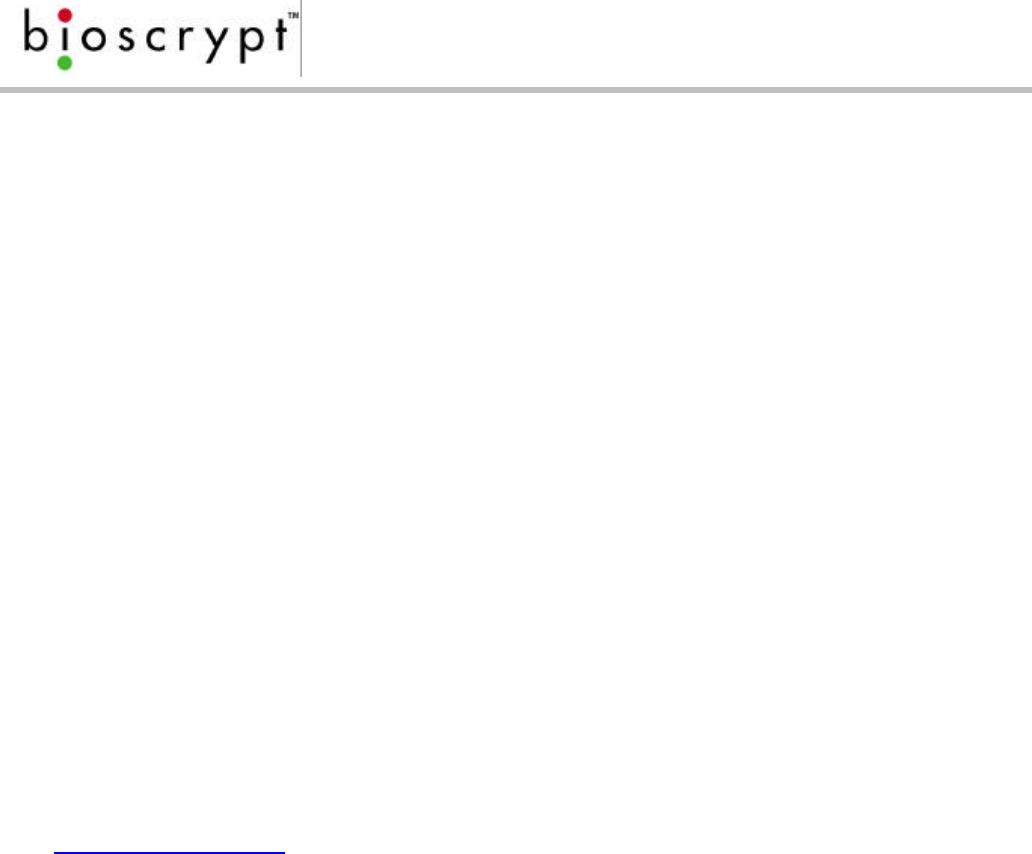
Bioscrypt’s V-Prox (figure 1) two-in-one solution combines a self-
contained fingerprint verification package about the size of a
business card (the MV1200), with an embedded proximity card
reader. The two technologies are housed together in a modern
case that conforms to mullion mount standards.
The V-Flex (figure 1) provides all of the same capabilities of the
V-Prox. Instead of having an embedded proximity card reader,
the V-Flex requires an external Wiegand input from a card
reader or keypad. Both the V-Prox and V-Flex store
thousands of templates.
The V-Pass (figure 1) reader does not use cards or PINs.
By simply placing your finger on the sensor, the device will
search through its database of hundreds of stored
templates and respond via Wiegand to a door controller
with the ID number of the user that matched the
candidate image.
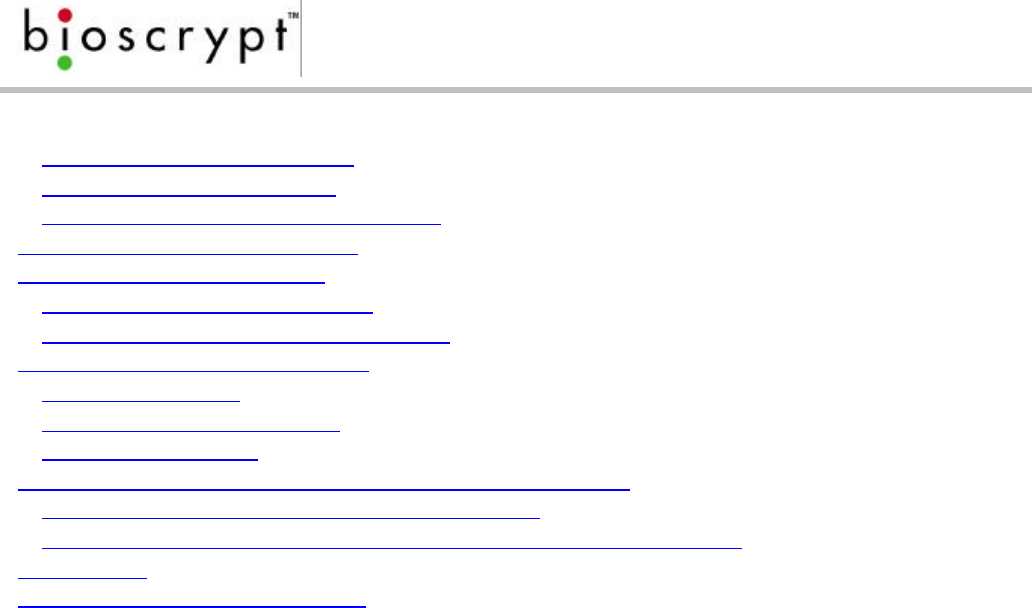
The V-Smart (figure 2) provides all the capability of the V-
Flex and includes an internal smart card reader (either
MIFARE or iCLASS). Fingerprint templates are securely
stored on a smart card and carried by the employee.
The smart card is presented to the V-Smart and the
template is read from the card and verified against the
employee’s live image. Storing the template on the smart card allows the V-Smart
to have an unlimited user base, removing the need for a physically-wired network.
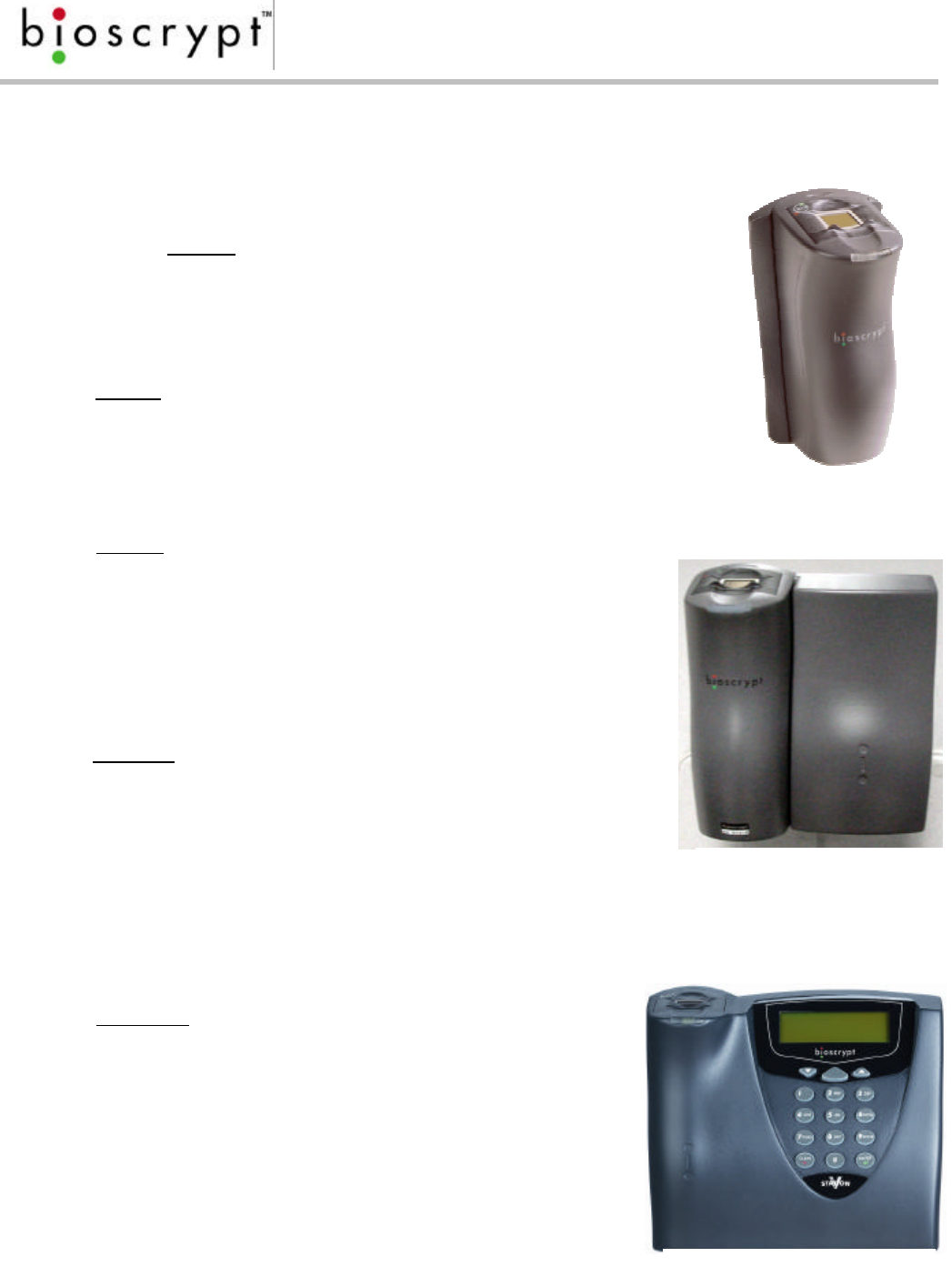
The V-Station (figure 3) is the first stand-alone version
of the Veri-Series product line with an integrated
keypad and LCD display. Many actions can be
performed right from the console, thereby freeing
users from having to administer the device from a PC.
The standard version stores more than 3000 templates
based on an ID entered on the keypad, but versions
are available which include an enclosed proximity
reader (V-Station A, P) or smart card reader (V-Station
Figure 2: The V-Smart
Figure 3: The V-Station
Figure 1: The V-Prox
/ V-Flex / V-Pass

Page 2
Document #430-90003-08 © Copyright 2003, Bioscrypt Inc. All rights reserved.
A, G and V-Station A, H). A searching version (V-Station A, S) is also available. In
addition, this is the first product to offer built-in Ethernet support, and is by far the
most flexible of the available devices.
All of the Veri-Series readers are stand-alone or network readers that perform
enrollment and verification and provide standard communication options that
enable it to be easily incorporated into access control systems.
The response time is less than 5 seconds for fingerprint enrollment and less than
one second for fingerprint verification. The system is compact, versatile, and can
be configured in a variety of ways. The readers support the industry-standard
Wiegand interface that can be used to connect to most any door controller or
alarm panel. The unit supports RS-232 for administration through a PC connection,
and it also supports RS-485 for multiple-unit operation and administration. The V-
Station also supports administration over an Ethernet network.
The Bioscrypt products use the latest generation of solid-state (chip) fingerprint
scanners or sensors. This type of sensor is being provided by a variety of
electronics manufacturers and the Veri-Series products are the only devices to be
compatible with a variety of sensors – this is Bioscrypt’s sensor interoperability.
The following paragraphs refer to operation and administration of the V-Prox
device, however the same functions can be performed through the VeriAdmin
software provided, or through the keypad on a V-Station.
The operation of the V-Prox is very simple: a user places or waves their card near
the V-Prox unit, the unit prompts the user to place their finger on the sensor
(communication is by means of a multi-colored LED), the V-Prox then reads the
fingerprint and compares it to a stored record of the user. If the comparison yields
a high degree of match, the user fingerprint is accepted and the user’s ID number
is transmitted to the access control unit over the Wiegand connection. If the
match fails, then either nothing is sent to the controller or a failure code is sent so
that the controller can log failed access attempts. The controller unlocks the door
for the user if the user has access. Therefore, the procedure is simple: present a
card, place finger, and open the door. The whole process takes less than 5
seconds.
Administration of the V-Prox is also simple. Any number of cards can be set up as
Enroll or Delete cards. These cards are maintained by the system administrator(s)
responsible for the access control system (one or more cards can be kept off-site
for added safety). To enroll a new user within a V-Prox unit, present an Enroll card,
verify the fingerprint of an authorized Enroller, present an unused card, and finally
place the finger of the user on the system. The user is now enrolled in this V-Prox
unit. If the installation has multiple V-Prox units you will have to either repeat this

Page 3
Document #430-90003-08 © Copyright 2003, Bioscrypt Inc. All rights reserved.
enroll process on other units or use software (if the units are connected via a RS-
485 or Ethernet network) to transfer the templates. The User ID will also have to be
added to the access control system. Deleting a user from the V-Prox is just as easy
– just use the Delete card instead of the Enroll card and follow the same
procedure.
All Veri-Series products also include an auxiliary port in the bottom of the unit. This
auxiliary port supports RS-232 communications with a host computer. You can use
this port to transfer templates, manage enroll and delete cards, etc.
An additional Ethernet port is now available on V-Station products, enabling
administration and template management over an Ethernet compatible network,
using the VeriAdmin software.

Page 4
Document #430-90003-08 © Copyright 2003, Bioscrypt Inc. All rights reserved.
About this Manual
This manual provides a simple step by step procedure for defining the RS-485 or
Ethernet network which will be used to communicate to a number of Veri-Series
readers as well as making connections to those readers. The Veri-Series Operation
Manual (under different cover) will provide the user or installer with information
required to configure the readers for communications on an RS-485 or Ethernet
network and for making other configuration changes such as for Wiegand format.
The V-Prox, V-Flex, and V-Pass readers are designed to be compatible with mullion
mount applications. Mullion mounting is not required, however, and the readers
can be mounted on any flat surface. The installer will want to take into account
codes and ordinances which affect the installation. The readers can also be
mounted on a single gang electrical box. Bioscrypt provides both a narrow and a
trimmed out wall plate for these applications.
Bioscrypt offers a Veri-Series Operations Manual under a separate cover. This
guide describes in complete detail the administration and day-to-day operation
of the Veri-Series unit. Bioscrypt also offers a Veri-Series Setup Guide, a quick step-
by-step guide for initial Veri-Series setup and use. Both of these are included on
the installation CD.
Page 5
Document #430-90003-08 © Copyright 2003, Bioscrypt Inc. All rights reserved.
Steps in a comprehensive installation
Every installation is unique. In some cases, the issues are well understood and can
be handled in a standard fashion. In other cases, there are issues that are specific
to the installation, and may not be immediately recognizable. This document
attempts to address many of the issues that you will be faced with during
installation. The steps for a successful installation are:
Ø Planning the installation – outlining the different components in the
installation, determining the interconnections between different
components, identifying issues specific to the installation
Ø Component selection – deciding on the right Veri-Series product(s) to use,
choosing a door controller, which type of proximity or smart cards to use,
which type of PC to use (optional, except for V-Pass), etc.
Ø Mounting – proper mounting hardware and location must be chosen in
accordance with applicable regulations as well as desired esthetics and
convenience
Ø Power Distribution / Device hook-up – proper power must be supplied to
each unit and consideration must be given to using UPS, avoiding
interference, proper grounding, etc.
Ø Cabling and Interconnection issues – the topology, type of network, and
type of cable used will be determined by requirements such as number of
units, distance between units, data throughput, etc. Each device on the
network must be assigned a unique ID (and IP address for Ethernet) to avoid
communication collisions
Ø Power-up procedure – units should be brought up one at a time in a
thoughtful sequence to help trouble-shoot any problem areas
The following sections will provide more information on each of these steps.
WARNING WARNING
Veri-Series devices must be installed by a qualified technician.

Page 6
Document #430-90003-08 © Copyright 2003, Bioscrypt Inc. All rights reserved.
Planning the Installation
Planning the installation is probably the single most important aspect to a
successful installation. Good planning will be comprehensive, accurate, and
adaptable. Planning for an Access Control installation must consider: the access
controller, the door locks, and the readers. Readers provide a means for the users
to request access to a controlled area. The Veri-Series products are different from
typical readers in that they provide not only verification of the presence of an
authorized card, but also the assurance that the authorized holder is presenting
the card.
During the planning phase, you should determine:
Ø How many doors need to be protected
Ø What type of reader on each door (maybe some doors are internal and
don’t require the added security of the Veri-Series)
Ø If multiple Veri-Series units are to be networked, a dedicated PC is
recommended to administer the system. This can be done through RS-232
(primary or auxiliary ports), RS-485, or via Ethernet (V-Station only).
Ø The controller must support any of the Wiegand formats supported by the
Veri-Series units.
Ø If the installation requires RS-485 or Ethernet network cabling for template
distribution/management
When planning the system, identify all wiring by the signal levels they are to carry.
Wires can be generally separated into the following groups:
1. Power distribution: Wires carry power to devices, door strikes, etc.
2. Data communication: RS485, RS-232, Ethernet, Wiegand, etc.
3. Sensor: Door contact, request to exit push button, alarm input, etc.
Use separate cable/conduit for different signal groups to avoid cross talk. Observe
the distance limitation of each type of signal when planning device placement.
Line extenders or repeaters can be used for extended distances when required.
Do not run any wires near utility AC power wiring, lightning rod grounding wire,
etc. to avoid externally generated transients. Grounding equipment is required for
ESD protection and safety.
Do research on the environment where the equipment will operate. If used
outdoors, it may be necessary to seal the readers or protect the installation with a
weather shield.

Page 7
Document #430-90003-08 © Copyright 2003, Bioscrypt Inc. All rights reserved.
Component Selection
Component selection will be based on customer demands and requirements. We
are glad that you are considering or have selected Bioscrypt products as part of
your system integration. We hope that you find the readers to be easy to use
while offering an unparalleled level of security.
The readers do not have built-in relays that would allow them to control a door
lock, and therefore, they must be part of a larger system such as a door control
system. Each of the Veri-Series readers offer RS-232 and RS-485 communications
channels for communicating with a PC or host controller. In addition, the V-
Station supports communication via a 10base-T Ethernet port. Each reader also
uses the Wiegand protocol to interface with Access Control equipment such as
door controllers (outputs) or additional readers (inputs).
Therefore, a minimum system would consist of a fingerprint reader unit mounted
on or near a door mullion, an electric lock, and the door controller. More
complex systems may consist of readers on multiple doors, each door with an
electric door lock, a multi-door controller, and a PC to run the door controller and
Veri-Admin management software. Some installations will require anti-passback
capabilities, and these will typically use standard proximity card readers
(compatible with the V-Prox system) on “request to exit”.
In addition to the hardware components, the installation will contain proximity or
smart cards, cabling, and will likely include a PC, an RS-232/RS-485 converter, and
software. Equipment for setting up an Ethernet network may also be needed,
including, hubs, switches, network cards, etc. Some installations may wish to utilize
a database or custom software for template management and access
scheduling.
Page 8
Document #430-90003-08 © Copyright 2003, Bioscrypt Inc. All rights reserved.
Mounting
The readers can be mounted to any flat surface. The
following describes the V-Prox/V-Flex/V-Pass mounting,
but the same concept applies to mounting the V-Smart
and V-Station (except for mullion mounting).
The mounting plate is 2 inches wide, which is suitable
for mounting in a door mullion. The mounting plate
hole pattern is also compatible with single gang box
mounting. The pig-tail protruding from the rear of the
unit is for connecting the reader to the rest of the
system.
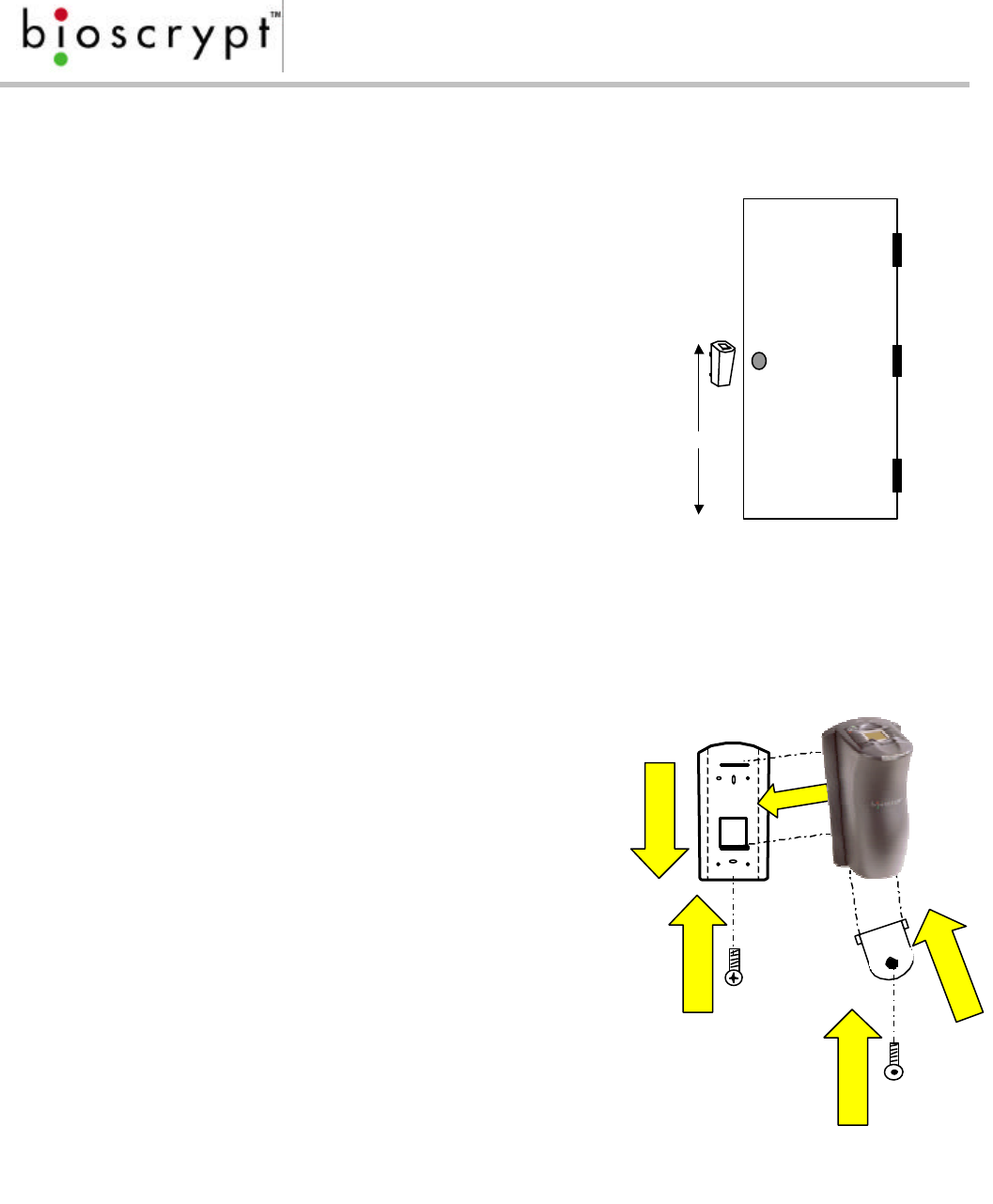
Factors in determining the position of the reader on the
wall should include mounting in-line with other switch
plates or fixtures, approximately 54 inches from floor to
top of unit (see figure 4), mounted on knob-side of door, and in accordance with
Americans with Disabilities Act.
Reader mounting is very simple. The mounting
plate is attached to the wall or mullion using screws
and anchors to secure it in place (see figure 4).
The reader body has two tabs which slide into the
wall plate. Use the following procedure:
1. Align reader body with wall plate
2. Slide reader body down, locking tabs into
wall plate
3. Set reader body in place with Phillips-head
#4-40 screw
4. Attach Aux. port door to bottom of reader
with a twisting motion
5. Secure door to reader with pin-in-hex #6-32
screw
All of the readers in the Veri-Series line are
constructed out of durable ABS plastic. The mounting plate is also constructed
out of ABS plastic. This system provides for a very lightweight, yet sturdy system.
48 – 54”
Figure 3: Positioning the
Reader
1
2
5
4
3
Figure 5: Mounting the reader to the
wall
Page 9
Document #430-90003-08 © Copyright 2003, Bioscrypt Inc. All rights reserved.
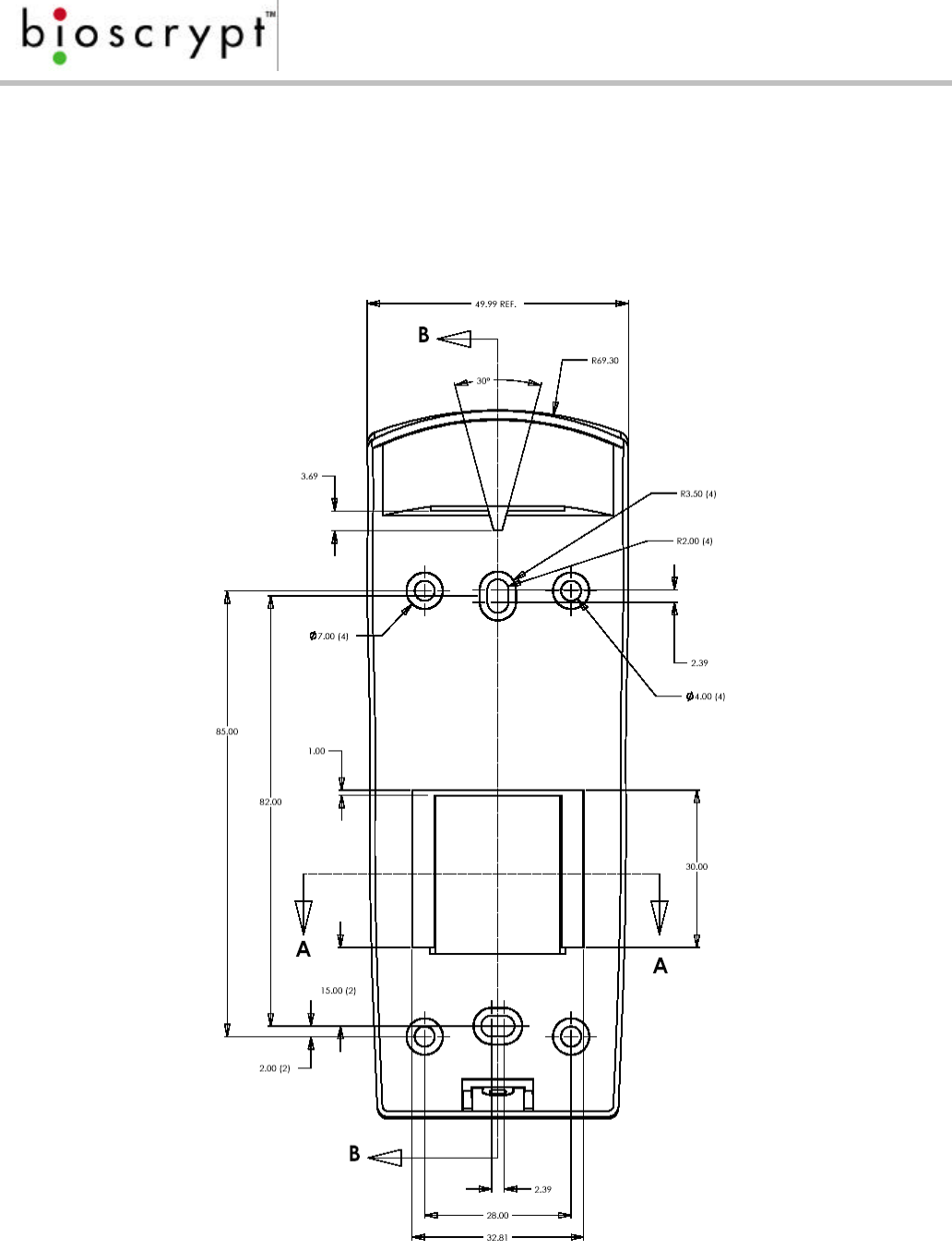
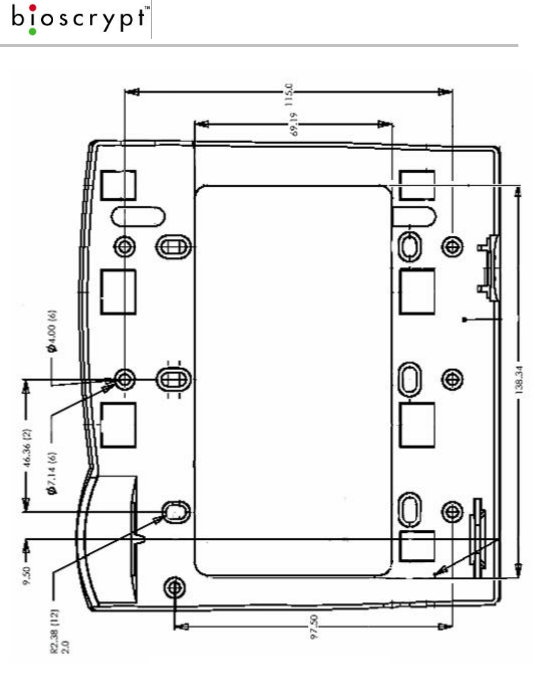
Mounting Templates
o For mounting into wall anchors, wood or sheet metal use #4 flat head
screws (<0.125 inch thread width, <0.250 inch head width).
o For mounting onto gang box, use #6-32 machine screws with flat head.
Figure 6: V-Prox/V-Flex/V-Pass Mullion Mounting Template
Page 10
Document #430-90003-08 © Copyright 2003, Bioscrypt Inc. All rights reserved.
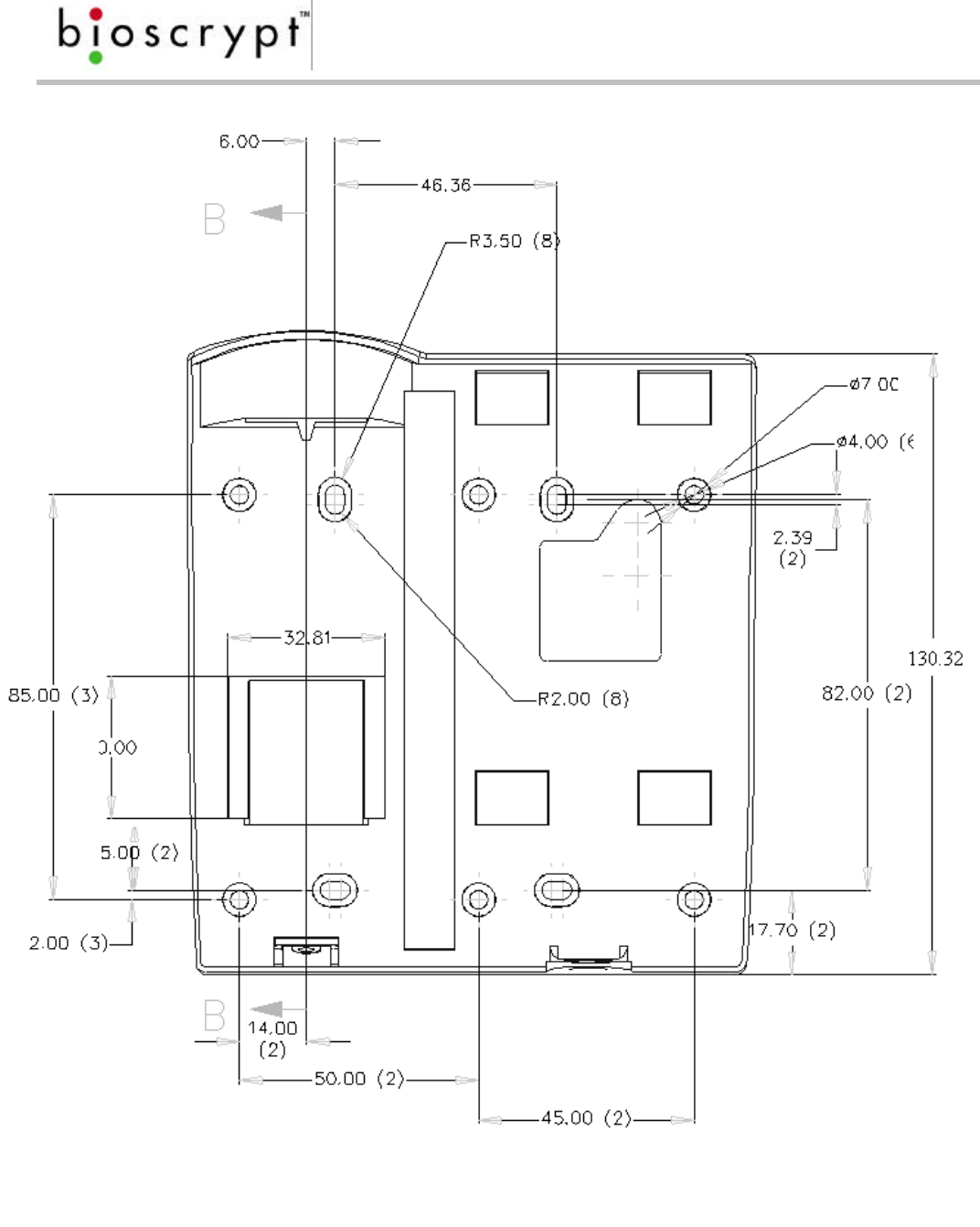
Figure 7: V-Smart Mounting Plate Template
Page 11
Document #430-90003-08 © Copyright 2003, Bioscrypt Inc. All rights reserved.
Figure 8: V-Station Mounting Plate Template
Page 12
Document #430-90003-08 © Copyright 2003, Bioscrypt Inc. All rights reserved.
Power Distribution & Device Hookup
The Veri-Series product as well as other components in the system will rely on
power provided to the system for operation. In a small installation, power may be
provided by means of an AC adapter placed near the V-Prox reader itself. In
larger installations, power will be distributed from either a central source or various
sources.
Power to the Veri-Series units should be:
o Isolated from other equipment
o Filtered
o Protected by means of a uninterruptible power supply (UPS) or battery
backup
o If transients are an issue in the installation, a transient voltage suppression
device is also recommended
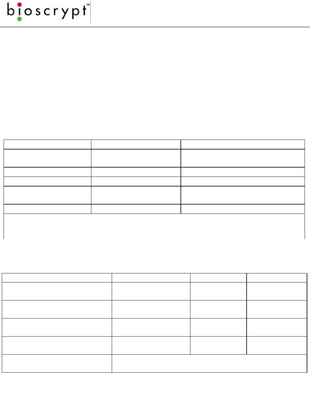
When planning a system, know the power requirement of each device. If multiple
devices are to share a common power supply, care must be exercised to avoid
excessive voltage loss on the wires. Voltage loss can lead to communication
problems when devices are talking/listening on different ground references.
Voltage loss is directly proportional to wire resistance and the current the wire
carries. Place the power supply as close to the equipment as possible. Select
appropriate wire size for the load. The Veri-Series readers run on DC power
between 6 and 24 VDC (V-Smart operates between 8-12V DC and V-Station
between 12-24V DC). Power requirements are as listed in Table 1.
V-Smart (all
models)
V-Prox/V-Flex/
V-Pass V-Station (all
models)
Power Requirement: 5 Watts 5 Watts 5 Watts
Input Voltage Range: 8-12VDC 6-24 VDC 12-24 VDC
Peak Current:
6 VDC N/A 800 mA N/A
12 VDC 400mA 400 mA 500mA
24 VDC N/A 200 mA 200mA
Current at 12 VDC:
Verification 300-400 mA 300-400 mA 300-400 mA
Idle (non V-PASS) 160 mA 60 mA 300 mA
Idle (V-Pass) N/A 150-200 mA N/A
Table 1: Veri-Series Power Requirements
Page 13
Document #430-90003-08 © Copyright 2003, Bioscrypt Inc. All rights reserved.
Selecting the Right Power Supply
Most power supplies in the market today provide good input/output isolation,
however those which do not provide isolation (or have hit leakage capacitance),
coupled with accidental AC power lines interchange, present serious ground fault
problems for installers. With ground fault, the signal reference between subsystems
may be 115 VAC apart. If these subsystems are interconnected, the large
potential difference will cause equipment damage or personal injury. We
recommend use of isolated power supplies only.
All factory supplied power supply assemblies are either switching or regulated
linear supplies and are isolated for safety and to minimize ground loop problems.
WARNINGWARNING
Use only a UL-Listed Class II power supply at 12V DC, 500mA.
Page 14
Document #430-90003-08 © Copyright 2003, Bioscrypt Inc. All rights reserved.
Device Hook-up (V-Prox/V-Flex/V-Pass/V-Smart)
The readers are connected to other components of an integrated system through
the pig-tail wire bundle that protrudes from the rear of the unit. This wire bundle is
made up of the connections described in Table 2.
PIN SIGNAL COLOR
Pigtail Jacket Blue
1Wiegand Data0 Out Green
2Wiegand Data0 In Green/White
3Wiegand Data1 Out White
4Wiegand Data1 In White/Black
5Line Trigger Gray
6Wiegand Ground Black/White
7RS-485 (-) Blue/Black
8RS-485 (+) Blue
9RS-232 (Tx)
*N/A on V-Smart Violet
10 RS-232 (Rx)
*N/A on V-Smart Violet/White
11 Power Ground Black
12 RS-232 Signal Ground Black/Red
13 Power In
8-12VDC - V-Smart
6-24VDC - all others except
V-Station
Red
14 5 VDC output
*N/A on V-Smart
*No-connect for MV1200
based units
Red/White
15 Earth Ground
Green/Yellow
Page 15
Document #430-90003-08 © Copyright 2003, Bioscrypt Inc. All rights reserved.
WARNING
The RJ-11 connector is intended for RS-232 communication only! Any attempt to
connect it to a phone line will damage the unit.
Table 2: Veri-Series Pigtail Connections
Page 16
Document #430-90003-08 © Copyright 2003, Bioscrypt Inc. All rights reserved.
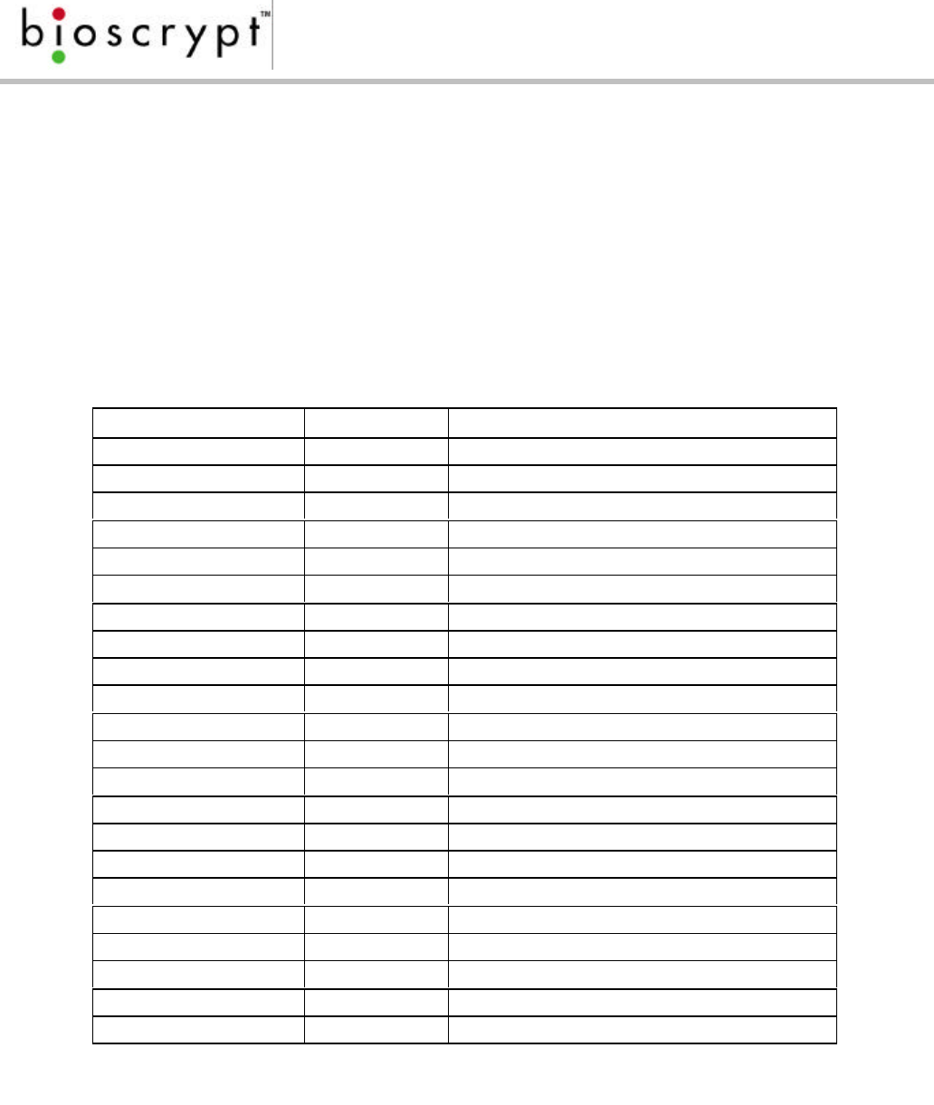
Device Hook-up (V-Station)
The V-Station readers do not have a pig-tail wire bundle as do the other Veri-Series
products. Connections are made using RJ-45/RJ-11 or Weidmuller connections.
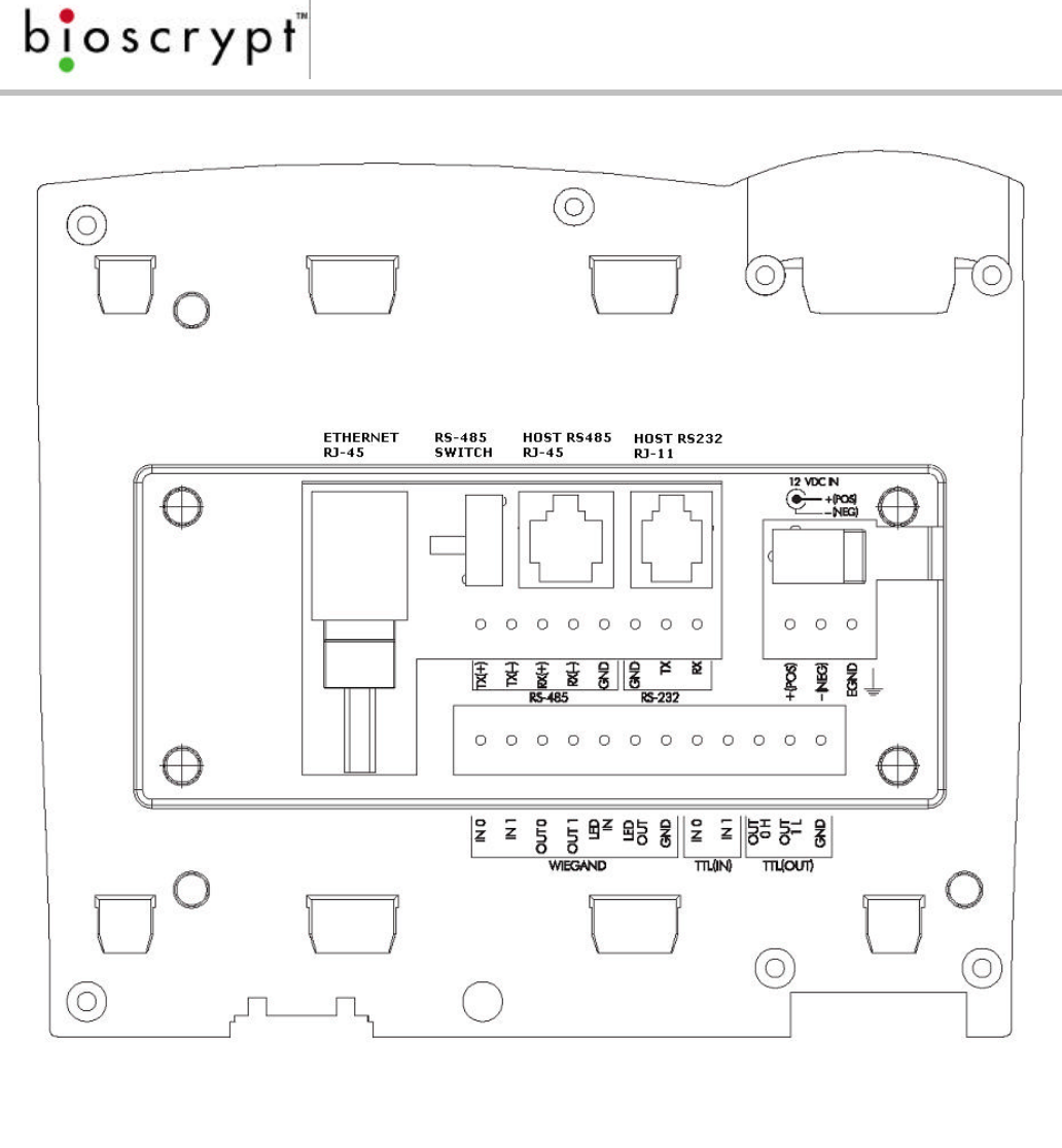
Tables 3 and 4, shown below, describe V-Station’s connections while Figure 9
shows the layout on the back of the V-Station.
GROUP PIN SIGNAL
Ethernet RJ-45 1Receive +
2Receive -
3Transmit +
4NC
5NC
6Transmit -
7NC
8NC
RS-485 RJ-45 1Transmit +
2Transmit -
3Ground
4Receive +
5Receive -
6NC
7NC
8NC
RS-232 RJ-11 1TX
2RX
3RTS*
4CTS*
5Ground
6NC
*Not connected but may be used in the future
Table 3: V-Station Ethernet, RJ-45, and RJ-11 Connections
Page 17
Document #430-90003-08 © Copyright 2003, Bioscrypt Inc. All rights reserved.
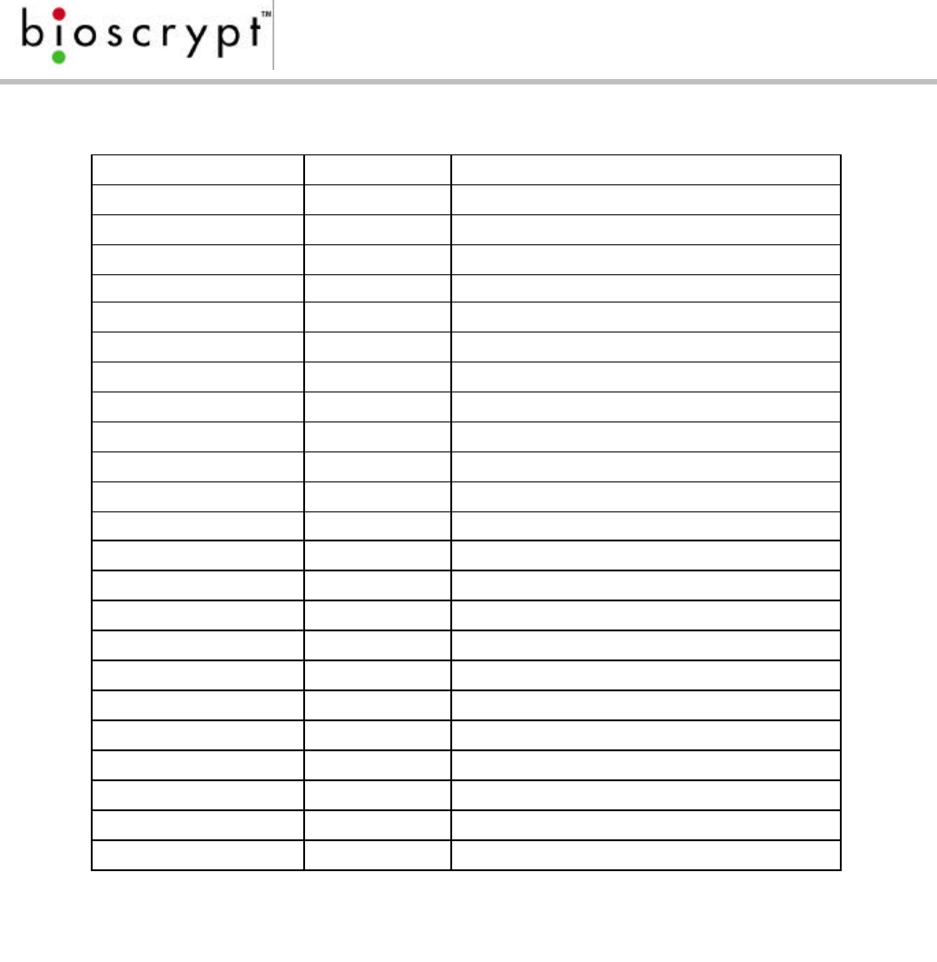
GROUP LABEL SIGNAL
RS-485 TX(+) Transmit +
TX(-) Transmit -
RX(+) Receive +
RX(-) Receive -
GND RS-485 Ground
RS-232 GND RS-232 Ground
TX Transmit
RX Receive
Power/E-Ground +(POS) 12 - 24 VDC +
-(NEG) 12 - 24 VDC -
EGND Earth Ground
Wiegand IN 0 Data 0 In
IN 1 Data 1 In
OUT 0 Data 0 Out
OUT 1 Data 1 In
LED IN LED In
LED OUT LED Out
GND Wiegand Ground
TTL (IN) IN 0 TTL Data 0 In
IN 1 TTL Data 1 In
TTL (OUT) OUT 0 H TTL Data 0 Out
OUT 1 L TTL Data 1 Out
GND TTL Ground
Table 4: V-Station Weidmuller Connections
Page 18
Document #430-90003-08 © Copyright 2003, Bioscrypt Inc. All rights reserved.
Figure 9: Rear Diagram of V-Station

Page 19
Document #430-90003-08 © Copyright 2003, Bioscrypt Inc. All rights reserved.
Wiegand Connections
Wiegand output lines should be connected to the Wiegand compatible
controller. When connecting Wiegand output to a controller, you must make that
connection using Data0, Data1, and a common Ground reference. Wiegand
input lines can be used for an alternate Wiegand input device (this connection is
required for the V-Flex device).
ESD Shield Earth Ground Requirement
The Finger mask (conductive plastic surrounding the fingerprint sensor) is
sometimes referred to as an ESD Shield. Pin 15 on the Pigtail (EGRND on the
input/earth-ground connector for V-Station) is connected to the ESD shield of the
fingerprint sensor. This should be connected in such a way as to make a low-
impedance connection to Earth ground. DO NOT CONNECT THE SHIELD TO
POWER GROUND. Improper connections will potentially create ground loops that
may cause damage to the Veri-Series and other equipment. Furthermore,
neglecting to provide a path for ESD to Earth ground puts the electronics at risk if
ESD is discharged into the unit from a user.
RS-485
RS-232 and RS-485 are used for communication with a PC running Veri-Series
compatible software (such as our VeriAdmin software). RS-485 connections
among various readers should be made by connecting the (+) and (-) lines of the
differential RS-485 in a daisy chain manner. For instance, from V-Prox to V-Prox,
the (+) line from one V-Prox is connected to the (+) line of the next V-Prox and so
on; likewise for the (-) lines. Additionally, connect the grounds from each V-Prox
unit back to the signal ground connection for the PC.
Ethernet (V-Station only)
The RJ-45 Ethernet connector can also be used for communication with a PC
running Veri-Series compatible software (Version 5.10 and above). Standard
Ethernet patch cables may be used, but care must be taken to identify straight-
through cables versus crossover cables. To wire a V-Station directly to a PC NIC
card, a crossover cable must be used. For connecting multiple V-Stations
together on an Ethernet bus or directly to a switch or hub, straight-through cables
should be used.
TTL (V-Station only)
The TTL Input/Output connections are standard 5V TTL Logic lines and are reserved
for future use.
Page 20
Document #430-90003-08 © Copyright 2003, Bioscrypt Inc. All rights reserved.
Cabling and Interconnection
Cabling may seem to be a trivial aspect to the installation, requiring nothing more
than planning the cabling route and pulling the cable through the building. This is
true for Wiegand and power wiring considerations, however, if your installation
requires the use of RS-485 or Ethernet communications, then the choice of cable,
the cable run length, the network topology, and termination of the network may
be very important aspects that must not be overlooked.
Parameter 10 Mbps 100 Mbps 1000 Mbps
Maximum collision diameter,
DTE to DTE 328 ft. UTP 328 ft. UTP
1352 ft. fiber 328 ft. UTP
1037 ft. fiber
Maximum collision diameter
with repeaters 8202 ft. 673 ft. 656 ft.
Maximum number of
repeaters in network path 5 2 1
Maximum number of devices
on one line 255 255 255
Maximum Data Rate* *V-Station supports only 10BaseT (10 Mbps); internally,
the product is still limited to 56K or 115K bps
Spec RS-485 RS-232
Mode of Operation: Differential DC
Coupled Single-ended DC Coupled
DC Isolation: No No
Max. Distance: 4000 ft. 200 ft.*
Number of Devices on
one line: 32 2
Max. Data Rate 56 kbps 56 kbps*
*RS-232 communications distances are dependent on baud rate (bps). For
example, at 9600 baud, a distance of 100 ft. is possible with shielded cable, but at
56 k-baud (kbps) a maximum of 20 ft. is recommended.
Table 5: RS-232 / RS-485 Communications Comparison
Table 6: Ethernet Comparison

Page 21
Document #430-90003-08 © Copyright 2003, Bioscrypt Inc. All rights reserved.
When is an RS-485 network required?
RS-485 is a networking specification similar to Ethernet, which is used for computer
networks. RS-485 is different from Ethernet and is not compatible with modern
computer networks. This means that you cannot connect most Veri-Series units
directly up to Ethernet networks. The V-Station does however support Ethernet.
RS-485 has two distinct advantages over the more common RS-232. First, it allows
you to connect up to 31 Veri-Series units to a PC (the PC will either need internal
support for RS-485 or will require an external RS-232/RS-485 converter available
from Bioscrypt). Second, the RS-485 specification allows for cable run lengths up
to 4000 feet (1200 meters) at modest baud rates.
An RS-485 network will need to be implemented in the following circumstances:
o There are multiple readers that must be connected together so that
templates can be distributed among the units
o There is only a single reader, but it is over 100 feet (30 meters) from the host
PC.
When is an Ethernet network required?
Ethernet is a networking specification now used all over the world for computers,
IP phones, and other devices. The only Bioscrypt product which currently supports
this standard is the V-Station. Ethernet has many advantages over an RS-485
network, namely, faster data transfer rates over greater distances. However, the
prime advantage to your network of Bioscrypt readers will be the ability to
connect many more units, enjoy easier configuration from the PC, and avoid
conflicts when multiple units transmit at the same time (i.e., if two or more units
have the same unit ID). Care must be taken to ensure the security of V-Stations
placed on a network which is also shared by PCs other than the administration
machine or other peripherals.
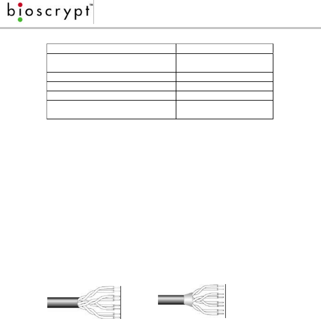
RS-485 Cable Specification
The Veri-Series readers provide a 2-wire, half-duplex RS-485 interface. The main
run cable should be low capacitance, twisted pair cable, with approximately 120-
ohm characteristic impedance. Category 5 rated communications cable is used
in Ethernet networks. This cable is typically 24 AWG (solid), unshielded, twisted-pair
with a shunt capacitance of approximately 17 pF/ft and characteristic
impedance of 100 – 120 ohms. This is the recommended cabling for RS-485
communications. In certain electrically noisy environments, a shielded cable may
be required.
Page 22
Document #430-90003-08 © Copyright 2003, Bioscrypt Inc. All rights reserved.
Spec Recommendation
Capacitance (conductor to
conductor) <20 pF/ft.
Characteristic Impedance 100 – 120 ohms
Nominal DC resistance <100 ohms/1000 ft.
Wire gauge 24 AWG stranded
Conductors/Shielding >2 pair (shielded
optional)
It is often hard to quantify if shielded cable is required in an application or not.
Since the added cost of shielded cable is usually minimal it is worth installing the
first time.
The total length of the communication cable (adding up all of the segments of
the run) must not exceed 4000 ft (1200 m) as outlined in the specification for RS-
485 (see reference 3).
Although the RS-485 specification calls out a maximum cable length of 1200
meters and a maximum baud rate well above that of the Veri-Series reader, a
more conservative system should be configured for no more than 1000 meters
and running at a baud rate of 9600 bits per second. After the network is
configured and is running in a stable manner, the baud rate can be increased if
faster network communications are desired.
Figure 10: Category 5 cable for RS-485/Ethernet Communications
Drops (down leads) to equipment are not recommended, but if required, should
not exceed 10 feet and should use the same cable recommended above.
Ethernet Cable Specification
Ethernet cables should generally be shielded Category 5 or better. The V-Station
supports only 10Base-T Ethernet. Therefore, it only makes sense to use cable for
Table 7: Recommended Cable Characteristics
Page 23
Document #430-90003-08 © Copyright 2003, Bioscrypt Inc. All rights reserved.
faster Ethernet varieties (such as gigabit) if PCs or other peripherals are to be
placed on the same network.
With most Ethernet networks, straight-thru cables should be used. However, in the
event of a single reader-to-PC network, a cross-over cable must be used. There
are other special considerations for such a network. Please see the next section
on connecting to the computer.
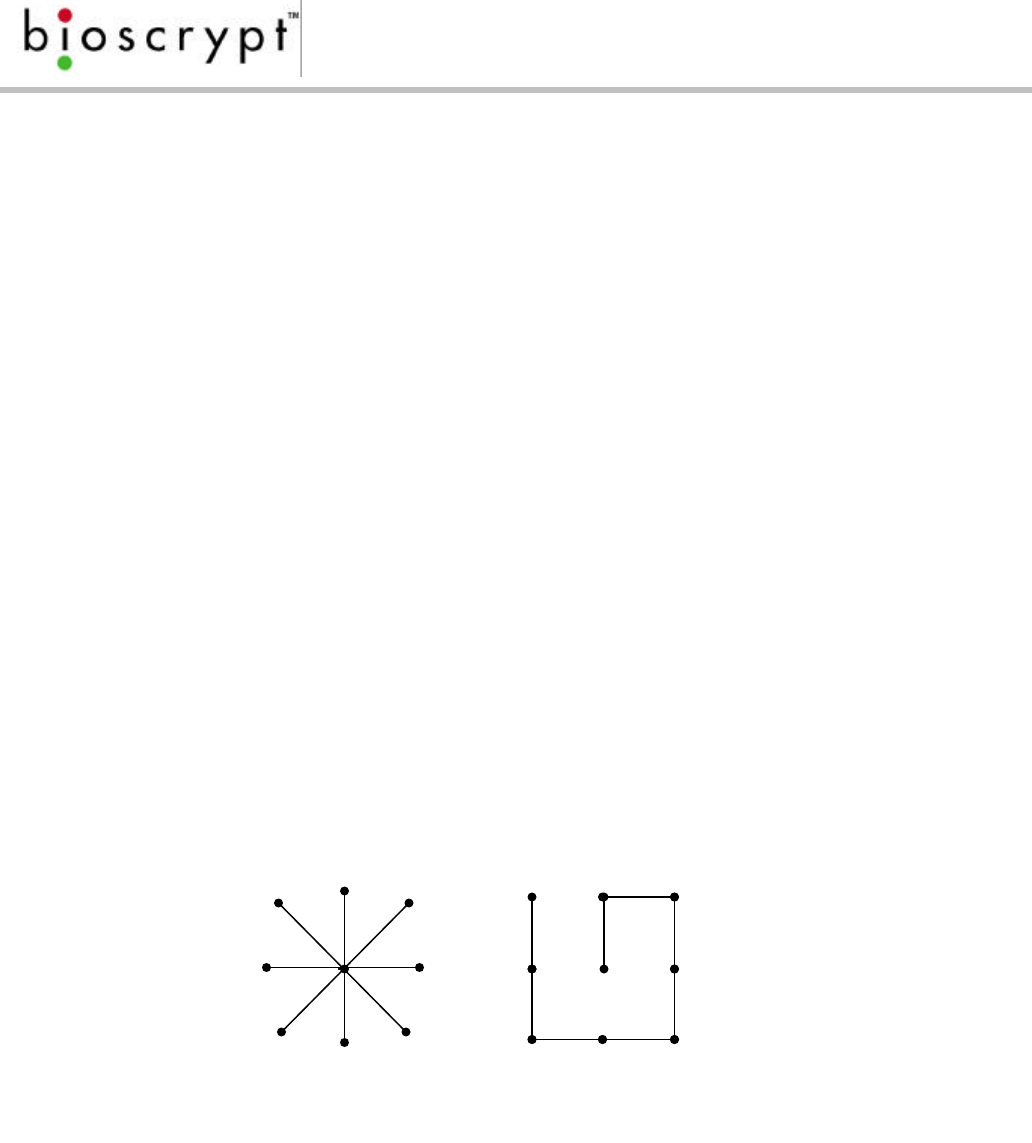
RS-485 Network Topology
Communication cables for RS-485 should be laid out in a daisy chain. See figure
11. Long stubs (T connections) should be avoided because they create
discontinuities and degrade signal quality. If the stub is long, a signal that travels
down the stub reflects to the main line after hitting the input impedance of the
device at the end of the stub. This impedance is high compared with that of the
cable. The net effect is degradation of signal quality on the bus. Keeping the stubs
as short as possible avoids this problem. Instead of adding a long branch stub,
loop the main cable to the device you wish to connect.
DO NOT connect devices in a STAR configuration – this creates long stubs and is a
cause for concern. This configuration usually does not provide a clean signaling
environment even if the cable runs are all of equal length. The star configuration
also presents a termination problem, because terminating every endpoint would
overload the driver. Terminating only two endpoints solves the loading problem
but creates transmission-line problems at the un-terminated ends. A true cascade
or daisy chain connection avoids these problems.
Figure 11: Network Topologies - STAR and CASCADE (Daisy Chain)

Page 24
Document #430-90003-08 © Copyright 2003, Bioscrypt Inc. All rights reserved.
Ethernet Network Topology
Communication cables for Ethernet logically form a straight line bus, however, the
more devices placed on that bus, the less efficient the network due to increased
collisions and the weaker the signal will get due to increased distance. Repeaters
can be used to boost signal strength, however a better solution would be placing
switches at intermediate positions along the bus. The most common Ethernet
topology in use today is the star configuration (see figure 11), with a hub or switch
in the center.
RS-485 Cable Termination
Most RS-485 buses require termination because of fast transitions, high data rates,
or long cables. The purpose of the termination is to prevent adverse transmission-
line phenomena, such as reflections.
For example, suppose an installation uses 2000 feet of cable. A round trip, then,
covers 4000 feet. Using a propagation velocity of 0.66c (two thirds the speed of
light – contact the cable supplier for this value for your cable), one round trip is
completed in approximately 6.2 micro-seconds. If we assume the reflections will
damp out in three round trips up and down the cable length, the signal will
stabilize 18.6 micro-seconds after the leading edge of a bit. At 56 k-baud (57,600
bits per second) one bit is 17.4 micro-seconds wide. In this case, the reflections do
not damp out before more information is being sent, and corruption of
information is a potential problem. Termination will solve this problem as will
lowering the baud rate. At 9600 baud, the bit width is 104 micro-seconds wide,
the reflections are damped out much before the center of the bit, and
termination is not required. Longer cable length and higher baud rates each push
the case for use of termination.
A common mistake is to connect a terminating resistor at each node - a practice
that causes trouble on buses that have four or more nodes. The active driver sees
the four termination resistors in parallel, a condition that excessively loads the
driver. If each of the four nodes connects a 100Ω termination resistor across the
bus, the active driver sees a load of 25Ω instead of the intended 50Ω. The problem
becomes substantially worse with 32 nodes. If each node includes a 100Ω
termination resistor, the load becomes 3.12Ω.
Page 25
Document #430-90003-08 © Copyright 2003, Bioscrypt Inc. All rights reserved.
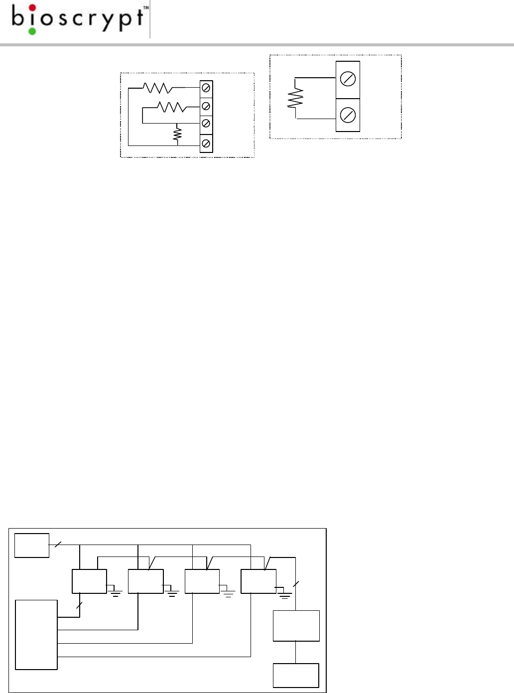
Figure 12: Termination Options - Failsafe (a) and Passive (b)
Bioscrypt recommends that the RS-485 transmission line be terminated at both
ends. The recommended termination at the PC end of the line is called Failsafe
termination. This terminator (shown in figure 12a) ensures that there is a proper
bias voltage across the receiver inputs. This, in turn, ensures that the receiver is in a
known state and puts less of a strain on the driver to provide that bias. This
termination is typically built into the RS-232/RS-485 converters and internal PC add-
on boards – you should confirm that such a termination exists, but you likely don’t
have to supply it yourself.
The termination at the opposite end of the transmission line should be parallel (or
passive) termination (see figure 12b). The value of R in figure 9b is chosen to
correspond to a proper parallel termination, RT, and it is chosen to be slightly
larger than the characteristic impedance of the cable, ZO. Over-termination tends
to be more desirable than under-termination since over-termination has been
observed to improve signal quality. RT is typically chosen to be equal to ZO. When
over-termination is used RT is typically chosen to be up to 10% larger than ZO. The
elimination of reflections permits higher data rates over longer cable lengths.
Power
Suppl
y
Unit Unit Unit Unit
3
Data0
Data1
Wiegand
Ground
2
RS-232
/RS-485
Converter
Cat5
Twisted
Pair
Compute
r
Door
Controll
er
R
R
R
+12 VDC
Gnd
-
+
R
- (B)
+ (A)
Page 26
Document #430-90003-08 © Copyright 2003, Bioscrypt Inc. All rights reserved.
Extending the RS-485 Specification
Some systems require longer distances or higher numbers of nodes than supported
by RS-485. Repeaters are commonly used to overcome these barriers. An RS-485
repeater can be placed in a system to divide the load into multiple segments.
Each “refreshed” signal is capable of driving another 4000 feet (1200 meters) of
cable and an additional 31 RS-485 unit loads. Using an Ethernet network with
switches can also solve this problem. The Veri-Series units represent a single unit
load to the transmission line.
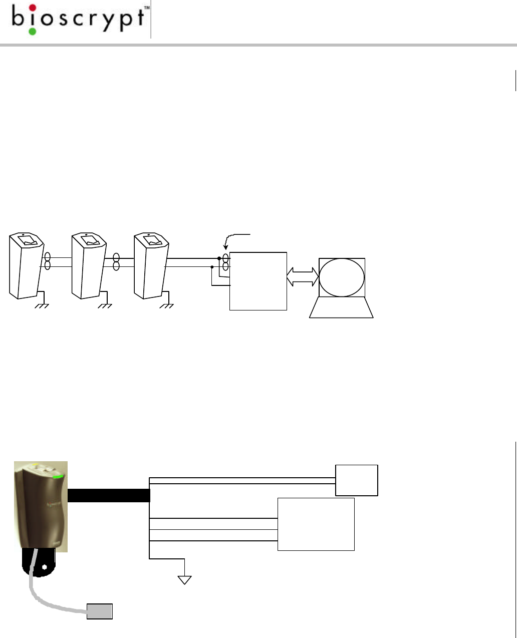
Figure 14: Wiring Diagram for RS-232/RS-485 Converter
Wiegand Ground
Wiegand Out Data1
Wiegand Out Data0
Power
Supply
+12 VDC
Ground
Pigtail
Door
Controller
Data 0
Data 1
Common
Earth
Ground
To
Computer
RS-232
TD(A)
TD(B)
RD(A)
RD(B)
+12VDC
GND
RS-485 (-)
RS-485 (+)
Connect to
Earth
Ground
Twisted Pair.
Use Cat5 rated cable
Figure 13: Network Configuration

Page 27
Document #430-90003-08 © Copyright 2003, Bioscrypt Inc. All rights reserved.
Figure 15: Reader Wiring Schematic

Page 28
Document #430-90003-08 © Copyright 2003, Bioscrypt Inc. All rights reserved.
Connecting to the Computer
The Veri-Series units can be connected to the computer either through an RS-232
communications link, an RS-485 link, or via Ethernet.
RS-485 and RS-232 are hardware specifications and software protocol is not
specified. It is up to the system designer to define a protocol suitable for the
system. Bioscrypt has done this with the Veri-Series reader system. Detailed
information on the software protocol can be obtained by contacting Bioscrypt.
RS-232 communications with the Veri-Series unit use RX, TX, and GND connections.
The primary communications port is wired through the pig-tail in the rear of the
unit. There is also an auxiliary RS-232 port accessible from the bottom of the unit.
The RS-485 implementation in the Veri-Series uses a two-wire, half-duplex
communication configuration. In RS-485 there can be only one master and all
other units are configured as slaves. A master-slave type system has one node
that issues commands to each of the “slave” nodes and processes responses.
Slave nodes will not typically transmit data without a request from the master
node, and do not communicate with each other. Each slave must have a unique
address so that it can be addressed independent of other nodes. In the Veri-
Series reader system the computer is the master and the readers are each slaves
on the network. To connect the computer to the RS-485 transmission line, you
must either have a computer with a built-in RS-485 transceiver or use a converter
attached to the computer’s standard serial port (an RS-232 device). The cable
connection includes a differential line (+ and -) and a GND connection.
With the addition of the V-Station products, installations may now connect to
these readers via an Ethernet network*. Because Ethernet enabled devices like
the V-Station contain unique pre-allocated addresses, there is no need to have a
slave/host configuration. Communication collisions are automatically handled by
the low-level Ethernet protocol. However, the Veri-Series reader protocol is still
used on top of TCP/IP communications protocols. Therefore, a unique IP
addresses must be assigned to each V-Station reader, either through the
VeriAdmin software/LCD Menu or automatically from a DHCP server on the
network**.
In the event that you are connecting a single V-Station directly to the computer’s
Ethernet adaptor, a cross-over cable must be used and the following steps must
be taken.
Both the PC and the V-Station must have assigned IP addresses where the
beginning numbers match in accordance with the subnet mask used on the PC.
For example, if the subnet mask is 255.255.255.0, both the PC and the V-Station
must be assigned an IP address of A.B.C.x where A, B, and C are the same for

Page 29
Document #430-90003-08 © Copyright 2003, Bioscrypt Inc. All rights reserved.
each and x is different. Additionally, the PC’s ARP table may need to be set at
the command prompt to resolve the Ethernet MAC address to IP address
translation. This last step is not needed on a normal Ethernet network which
consists of more than just a single PC-to-V-Station connection. Please see the Veri-
Series Operations Manual for more information on this topic.
* Ethernet is fully supported in V-Station firmware versions 7.10 and above
** DHCP support may not be available in some versions

Page 30
Document #430-90003-08 © Copyright 2003, Bioscrypt Inc. All rights reserved.
System Turn-up Procedures
System turn-up must follow a step-by-step procedure. Never wire up a system and
apply power to it all at once. This can turn a potential success into an immediate
disaster.
The following steps should be observed:
1. Do not apply power to any units.
2. Check all wiring and device configuration.
3. Disconnect all units from RS-485 communication line.
4. Check for the correct supply voltage before connecting it to any device.
5. Power up the PC running the VeriAdmin or other software that is designed
to work with the Veri- series readers. The RS-232 to RS-485 converter should
also be powered up at this time. If communicating to units via Ethernet, be
sure the correct cable is connected to the PC NIC card.
6. Configure the PC software.
7. Check for ground fault between the converter and the RS-485
communication line (see figure 13). Find any faults and clear them if they
exist.
8. Connect the PC and converter to the RS-485 line.
9. Power up a SLAVE (V-Prox or other reader), but DO NOT connect it to the
RS-485 line. Verify that it powers up correctly.
10. Check for ground fault between this unit and the RS-485 communication
line. Find any faults and clear them if they exist.
11. Connect this unit to the RS-485 line.
12. Verify that it communicates with the PC software.
13. If there are more SLAVES (V-Prox or other readers), add the subsequent
readers by repeating steps 9-12.
Device Configuration Check
Devices must be configured correctly before they can communicate. Common
problems include not correctly selecting RS-485 as the Com Port, mismatched
baud rates, and incorrect device addresses. Each device sharing the RS-485 line
must have a unique address.

Page 31
Document #430-90003-08 © Copyright 2003, Bioscrypt Inc. All rights reserved.
Ground Potential Difference Check
Before a device is connected to an RS-485 subsystem, it must be checked for
ground fault. An uncorrected ground fault can damage all devices connected
to the RS-485 communication line.
To check if there is ground fault for a new unit, follow the steps below:
1. Apply power to all devices already successfully connected to RS-485 line.
2. Power up a new unit, but DO NOT connect it to RS-485 line.
3. Connect the signal ground of the RS-485 line through a 10-kΩ current limiting
resistor to the signal ground (see Table 2) of the Veri-Series unit. There should
NOT be more than 1 volt across the resistor. Otherwise find and clear the
fault.
4. Repeat the steps in #3 with each of the RS-485 signal lines (+ and –)
5. Connect the new unit to the RS-485 line only if no ground fault is found.

Page 32
Document #430-90003-08 © Copyright 2003, Bioscrypt Inc. All rights reserved.
General Installation Guidelines
Installation Issues:
o Use Category 5 cabling for a RS-485 network
o Use Category 5 shielded cabling for a 10Base-T or 100Base-T Ethernet network
and Category 5E cable for Gigabit (1000Base-T) Ethernet and beyond
o Choose one twisted pair of conductors to use for RS-485 differential
connection, other conductors should be used for Signal Ground (Black with
Red stripe from Veri-Series)
o For Ethernet, use a straight-through cable when connecting DTE (V-Station, PC,
etc) to DCE (Switch, Hub, Repeater, etc). Use a crossover cable when
connecting DTE to DTE or DCE to DCE
o RS-232/RS-485 Converter must support “sense data” to switch from send to
receive mode
o If placing a V-Station on a RS-485 network, be sure to set the switch in back to
“RS-485 enable”
o Before connecting each unit to the network, do the following:
v Configure the reader using the auxiliary port (RS-232) and a PC (or
directly from the console if a V-Station)
§ Set Network ID to a unique number
§ If a V-Station on Ethernet, set its IP address explicitly, or use DHCP
§ Set host port to RS-485
§ Set host port baud rate to 9600 bps
v Check each unit/cabling for ground fault before connecting to RS-485
network
v Each unit should have its ESD Shield Ground (Green with Yellow stripe)
connected to Earth Ground (EGND connection on V-Station)
v Once all units are configured and connected to the RS-485 network, the
baud rate can be increased to highest supported rate (some
experimentation required)
Network Operation Issues:
o Do not use auxiliary port when RS-485 network is active
o Unit will return a “busy” signal (error –104) if communication cannot be
processed due to current processing – usually enroll or verify

Page 33
Document #430-90003-08 © Copyright 2003, Bioscrypt Inc. All rights reserved.
o V-Stations communicating over the Ethernet port can only accept one
connection at a time
o V-Stations must not be assigned an IP address which is already in use or a
conflict will arise, causing communication errors on both devices
o If using Ethernet, an appropriate subnet mask should be set in VeriAdmin to
ensure proper broadcasting capability to all units on the network. For
example, a class C network (supporting up to 254 readers) should have a
subnet mask of 255.255.255.0. If multiple class C networks are being used within
the same network, the subnet mask should resemble the form 255.255.x.0
where x appropriately masks out the bits common to both network addresses.
o Broadcasting to all V-Stations on a network is accomplished in VeriAdmin using
UDP, a connectionless datagram protocol. This is not a reliable protocol, and
V-Stations will not respond to broadcast communications to verify proper
delivery of the message. This should be used as a convenience but not relied
upon as a guaranteed communication method. This is especially true if
packets are routed, like over the Internet.
Operational Issues:
o V-Prox Cards registered as Command Cards (enroll or delete cards) cannot be
used as user cards
o The V-Pass system requires a PC running VeriAdmin or compatible software in
order to enroll fingerprints

Page 34
Document #430-90003-08 © Copyright 2003, Bioscrypt Inc. All rights reserved.
Appendix A – Installing the R&TTE Installation Kit Filters
The following two sections describe the proper procedures for installing the R&TTE
Installation Kit filters, which are required in certain European countries for full CE
compliance. These kits are required only for the V-Prox and V-Smart products and
are not required for any other Bioscrypt product. More information can be found
regarding the CE R&TTE directive online at the European Union web site:
http://www.europa.eu.int/comm/enterprise/rtte/index.htm
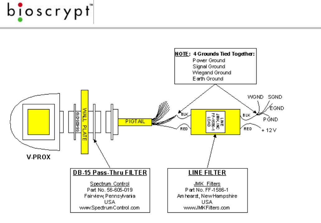
R&TTE Wiring Instructions for the V-Prox, A, H
In order to comply with the conducted emissions requirements of the European
Union (EU) directive EN 55022 for DC power input/output ports, an additional line
filter is needed for installations where power supply cables are greater than 3
meters in length. The required filter is manufactured by JMK Filters (Amhearst, New
Hampshire, USA), Part No. FF-1586-1, and is shipped as part of the installation kit.
Please note the orientation of the filter: the end labeled “LOAD” is to be
connected to the V-Prox device, the end labeled “LINE” is to be connected to
the system power supply.
In order to comply with the radiated emissions requirements of the European
Union R&TTE directive CISPR22, a high-density DB-15 “pass-thru” filter is required.
The required filter is manufactured by Spectrum Control (Fairview, Pennsylvania,
USA), Part No. 56-605-019, and is shipped as part of the installation kit. Please note
that it is necessary to rotate the filter to pass through the aperture of the wall plate
or mullion. It is easiest if the filter is first connected to the pigtail wiring harness
supplied. The cable assembly (and connected filter) is now rotated 90 degrees to
allow passage through the aperture of the wall plate. The V-Prox device should
next be connected to the cable assembly, and then pushed back through the
aperture until the wall plate is between the two mounting flanges of the filter. The
device may now be rotated back 90 degrees to the upright position and lowered
onto the mounting hooks of the wall plate.
Please see figure 16 for wiring details.
Page 35
Document #430-90003-08 © Copyright 2003, Bioscrypt Inc. All rights reserved.
R&TTE
Wiring
Instru
ction
s for
the
V-
Smart
, A
and
V-
Smart
, A, H
In
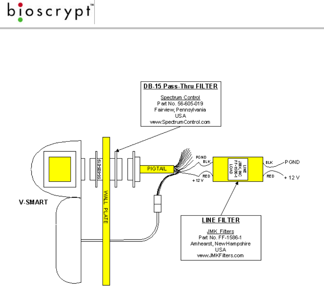
order to comply with the conducted emissions requirements of the European In
order to comply with the conducted emissions requirements of the European
Community directive EN 55022 for DC power input/output ports, an additional line
filter is needed for installations where power supply cables are greater than 3
meters in length. The required filter is manufactured by JMK Filters (Amhearst, New
Hampshire, USA), Part No. FF-1586-1, and is shipped as part of the installation kit.
Please note the orientation of the filter: the end labeled “LOAD” is to be
connected to the V-Smart device, the end labeled “LINE” is to be connected to
the system power supply.
In order to comply with the radiated emissions requirements of the European
Community R&TTE directive CISPR22, a high-density DB-15 “pass-thru” filter is
required. The required filter is manufactured by Spectrum Control (Fairview,
Pennsylvania, USA), Part No. 56-605-019, and is shipped as part of the installation
kit. Please note that it is necessary to rotate the filter to pass through the aperture
of the wall plate or mullion. It is easiest if the filter is first connected to the pigtail
wiring harness supplied. The cable assembly (and connected filter) is now rotated
90 degrees to allow passage through the aperture of the wall plate. The V-Smart
device should next be connected to the cable assembly, and then pushed back
through the aperture until the wall plate is between the two mounting flanges of
the filter. The device may now be rotated back 90 degrees to the upright position
and lowered onto the mounting hooks of the wall plate.
Please see figure 17 for wiring details.
Page 36
Document #430-90003-08 © Copyright 2003, Bioscrypt Inc. All rights reserved.
Figure 17: V-Smart R&TTE Installation Kit Wiring Diagram

Page 37
Document #430-90003-08 © Copyright 2003, Bioscrypt Inc. All rights reserved.
References
(1) B & B Electronics offers an Application Note on RS-485 devices, system
configuration, and termination.
B & B Electronics
707 Dayton Road
P.O. Box 1040
Ottawa, IL 61350
(815)433-5100
http://www.bb-elec.com/bb-elec/literature/485appnote.pdf
(2) Robust Data Comm provides services and a vast amount of information at
their WWW site.
Robust Data Comm, Inc.
St. Paul, MN 55112
(612)628-0533
http://www.robustdc.com/rdc_apno.htm
(3) The Specification is formally named TIA/EIA-485-A and can be purchased
from Global Engineering Documents:
http://global.ihs.com/cgi-bin/detdoc.cgi?FRITTER=111167&DOCID=6798420
(4) National Semiconductor provides a number of Application Notes:
http://www.national.com/an/AN/
(5) Belden Wire and Cable Company offers a variety of cables suitable for RS-
485 use and has a number of technical papers:
http://www.belden.com/products/techpprs.htm
Page 38
Document #430-90003-08 © Copyright 2003, Bioscrypt Inc. All rights reserved.
(6) Alpha Wire Company offers a variety of cables suitable for RS-485 use and
has a number of technical papers:
http://www.alphawire.com/index_4.html
(7) Cisco Systems, Inc., provides a comprehensive guide to Ethernet 802.x
standards and implementation issues:
http://www.cisco.com/univercd/cc/td/doc/cisintwk/ito_doc/ethernet.htm
(8) Charles Spurgeon provides an excellent online Ethernet resource:
http://www.ethermanage.com/ethernet/ethernet.html
(9) The CE R&TTE directive is outlined on the EU website at:
http://www.europa.eu.int/comm/enterprise/rtte/index.htm

Page 39
Document #430-90003-08 © Copyright 2003, Bioscrypt Inc. All rights reserved.
Bioscrypt Contact Information
Technical Support Contact Information:
Telephone: 866.304.7180 (toll free)
818.304.7180
Email: support@bioscrypt.com
Address Bioscrypt Inc
Technical Support Dept
5805 Sepulveda Blvd.
Suite 750
Van Nuys, CA 91411
Corporate & Canadian Office
5450 Explorer Drive, Suite 500
Mississauga, ON, Canada L4W
5M1
T 905.624.7700
F 905.624.7742
www.bioscrypt.com
U.S. Office
5805 Sepulveda Blvd.,
Suite 750
Van Nuys, CA 91411 U.S.A.
T 818.304.7150
F 818.461.0843
support@bioscrypt.com