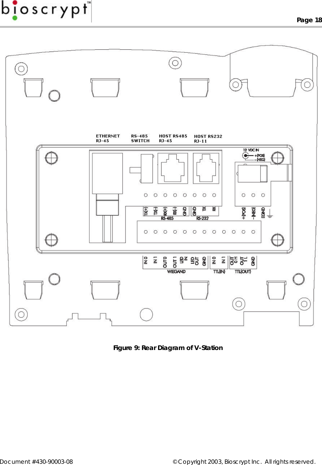
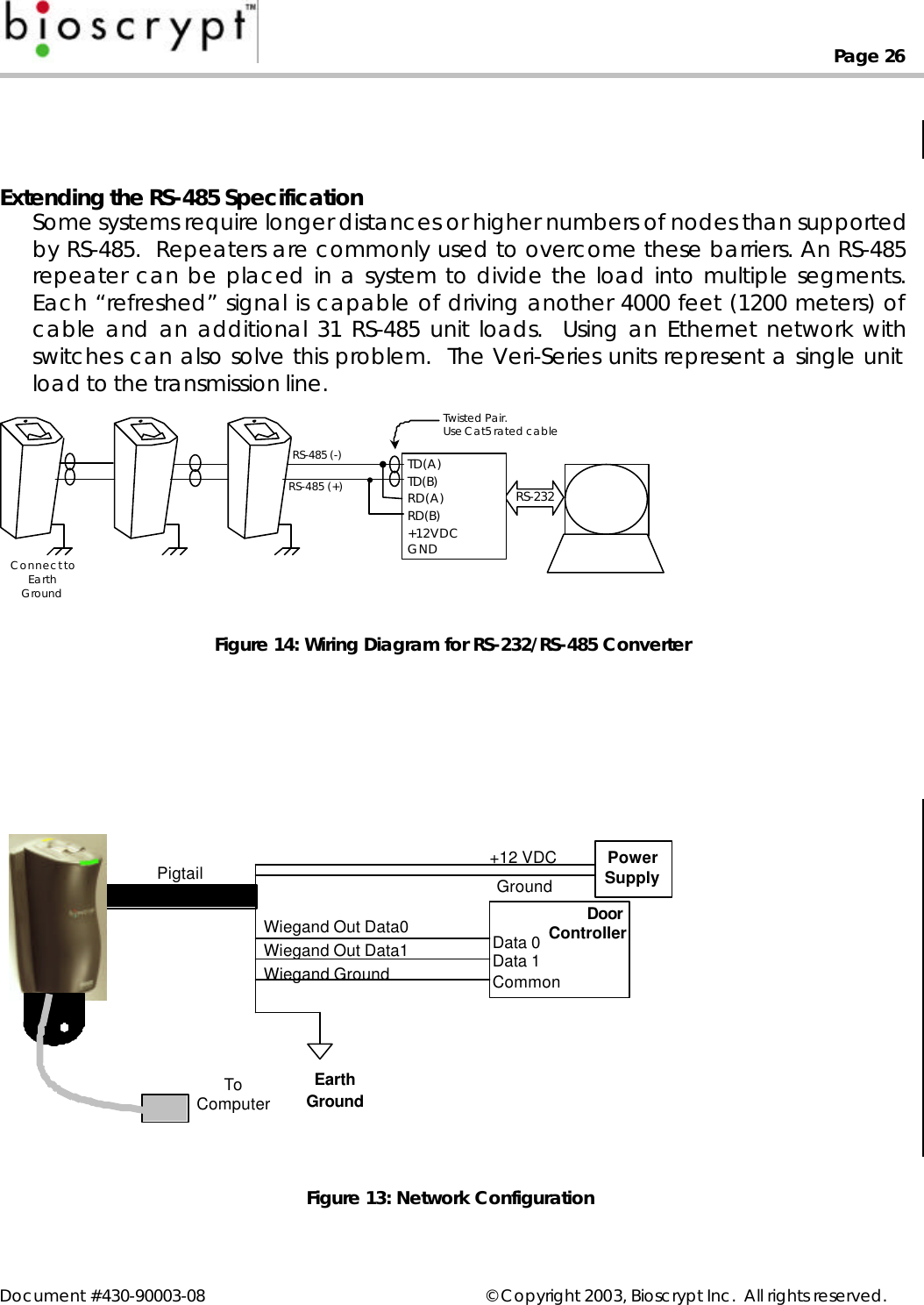
Bioscrypt VSTNAPR V-STATION, A, P, R, (RFID READER) User Manual Veri Series Installation Guide

Bioscrypt, Inc. V-STATION, A, P, R, (RFID READER) Veri Series Installation Guide

USERS MANUAL

Document #430-90003-08 © Copyright 2003, Bioscrypt Inc.  All rights reserved.Bioscrypt Inc.Veri-Series Installation Guide
Page iiDocument #430-90003-08 © Copyright 2003, Bioscrypt Inc.  All rights reserved.IntroductionBioscrypt is proud to present the Veri-Series line of fingerprint authenticationreaders including the V-Prox™, V-Flex™, V-Pass™, V-Smart™, and V-Station™.  TheV-Prox™, includes integrated proximity reader and fingerprint verification.  The V-Flex™ allows for upgrading existing installations and using other card technologies.The V-Pass™ doesn’t require any cards or PINs, and searches through up to 200fingerprints.  The V-Smart™ incorporates contact-less smart card technology sothat a hardwired network is no longer needed.   Finally, the V-Station™, the mostflexible of the group, offers convenient administration right from its console andnow supports Ethernet.  Select versions provide functionality found in each of theVeri-Series products, including a proximity or smart card reader, and searchingability.Bioscrypt's product offerings leverage over 20 years of experience designingsystems for the US Department of Defense. The company's mission is to bring theirpatented fingerprint verification technology, once found only in government ormilitary applications, to a wide range of commercial applications around theglobe at a reasonable cost.The V-Prox, V-Flex, V-Smart, and V-Station readers prevent unauthorized accessvia loaned, lost or stolen proximity or smart cards by requiring that the fingerprintof the person seeking entry match the identity of the cardholder. Its ability to verifyfingerprints in the face of adverse conditions like soil and other contaminantsmakes the Veri-Series readers useful for factories, plants, construction sites andsimilar environments that have previously been unable to implement biometric-based access solutions.The V-Pass reader and V-Station searching version capitalize on this samefundamental algorithm for matching fingerprints but implement it in such a way asto be able to search through a database of templates to find the matchingtemplate.  Therefore, these systems negate the need for cards at all, providing aconvenient yet secure access control solution.Fingerprint verification has been around for over 100 years, but during that time ithas progressed from an intensive manual operation to an automated computeroperation.  The Veri-Series readers represent the state-of-the-art in fingerprintverification technology.  It uses a 100% solid-state design.  There are no movingparts, no optics or lenses, and it provides a variety of communications options.
Page iiiDocument #430-90003-08 © Copyright 2003, Bioscrypt Inc.  All rights reserved.DisclaimerThe instructions in this document have been carefully checked for accuracy andare presumed to be reliable. Bioscrypt, Inc. and its writers assume no responsibilityfor inaccuracies and reserve the right to modify and revise this document withoutnotice.It is always our goal at Bioscrypt, Inc. to supply accurate and reliabledocumentation. If you discover a discrepancy in this document, please e-mailyour comments to support@Bioscrypt.com, or contact Bioscrypt Technical Supportat the telephone number listed below.No part of this publication may be placed in a retrieval system, transmitted, orreproduced in any way, including, but not limited to, photograph, photocopy,computer disk or other record, without prior agreement and written permissionfrom:Bioscrypt Inc.5805 Sepulveda Blvd., Suite 750Van Nuys, CA 91411Phone 818.304.7150Toll Free 888.982.4643http://www.bioscrypt.comNOTENOTE:  This symbol, found both on the device and throughout thismanual, denotes a caution or warning.  When this symbol isencountered during setup or installation, please be sure to firstcarefully read the corresponding section in this manual.
Page ivDocument #430-90003-08 © Copyright 2003, Bioscrypt Inc.  All rights reserved.Bioscrypt One Year Limited Warranty PolicyBioscrypt warrants to the original consumer purchaser (“Customer”) that newBioscrypt products will be free from defects in material and workmanship for oneyear from the date the product was shipped from Bioscrypt.  For replacementproducts the warranty on the replacement unit is the remainder of the warrantyon the original product or ninety (90) days, whichever is longer.  The Customer isresponsible for making any claims for shipment damage (evident or concealed)with the freight carrier.  Bioscrypt must be notified within thirty days of shipment ofincorrect materials.If a defect is discovered, Bioscrypt's sole obligation shall be to repair or replacethe Bioscrypt product(s) at its sole discretion at no charge, provided it is returnedto Bioscrypt during the warranty period and is shipped freight and insuranceprepaid.  Merchandise must be properly packaged to prevent damage duringshipping.  Before returning a Bioscrypt product, contact Bioscrypt TechnicalService to obtain a Return Material Authorization (RMA) number.  No product maybe returned whether in warranty or out of warranty without first obtainingapproval from Bioscrypt.  The model number, invoice number, and serial numbermay be required for warranty service.This warranty shall not apply to any product or any part of a product, which in thejudgment of Bioscrypt, has been subjected to misuse, negligence, alteration,accident, improper maintenance, or damage by excessive physical or electricalstresses.  Tampering, such as opening the housing of a biometric reader orreplacing parts will void this warranty.  The warranty is void if the serial number ofthe Bioscrypt product has been defaced, altered, or removed or if the producthas been modified.  Repair and replacement parts will be furnished on anexchange basis and may be either reconditioned or new.  All replaced parts orproducts become the property of Bioscrypt.  This warranty may also be voided forfailure to comply with Bioscrypt’s return policy.The warranty is not applicable to:• Abnormal wear and tear• Damage caused during installation• Damage caused by the equipment or system with which the biometric readeris used• Damage caused by modification or repairs not made or authorized byBioscrypt• Damage caused by improper packaging
Page vDocument #430-90003-08 © Copyright 2003, Bioscrypt Inc.  All rights reserved.• Damage caused by lack of ESD protection• Merchandise that is determined to be stolenThe newest Bioscrypt Veri-Series products are designed to be weather resistant butno sensor technology exists today that can work in all weather environments. If aBioscrypt Veri-Series product is not used in a completely indoor environment, thena protective cover is required to shield the sensor from moisture, dust, and othercontaminants that will degrade sensor operation and void the product warranty.This warranty is exclusive and in lieu of all others, whether oral or written, expressedor implied.  Bioscrypt specifically disclaims any and all implied warranties,including without limitation, warranties of merchantability and fitness for anyparticular purpose. No Bioscrypt dealer, agent, or employee is authorized to makeany modification, extension or addition to this warranty.
Page viDocument #430-90003-08 © Copyright 2003, Bioscrypt Inc.  All rights reserved.NoticesThe Veri-Series line of products have been tested for compliance with allapplicable international standards.  The resulting approvals are listed below, andare additionally printed on the labeling located on the rear panel of the product.The power supply offered by Bioscrypt is CE and CSA approved and UL listed.V-Flex FCC, UL, ULC, CEV-Prox FCC, UL, ULC, CEV-Pass FCC, UL, ULC, CEV-Smart FCC, UL, ULC, CEV-Station FCC, UL, ULC, CEFCC Information to UsersThis equipment has been tested and found to comply with the limits for a Class Adigital device, pursuant to Part 15 of the FCC Rules. These limits are designed toprovide reasonable protection against harmful interference when the equipmentis operated in a commercial environment. This equipment generates, uses, andcan radiate radio frequency energy and, if not installed and used in accordancewith the instruction manual, may cause harmful interference to radiocommunications. Operation of this equipment in a residential area is likely tocause harmful interference in which case the user will be required to correct theinterference at his own expense.FCC Class B Digital Device or Peripheral - User’s Notice (for all V-Station models only)This equipment has been tested and found to comply with the limits for a Class Bdigital device, pursuant to Part 15 of the FCC Rules. These limits are designed toprovide reasonable protection against harmful interference in a residentialinstallation. This equipment generates, uses, and can radiate radio frequencyenergy and, if not installed and used in accordance with the instruction manual,may cause harmful interference to radio communications. However, there is noguarantee that interference will not occur in a particular installation. If thisequipment does cause harmful interference to radio or television reception, whichcan be determined by turning the equipment off and on, the user is encouragedto try to correct the interference by one of more of the following measures:• Reorient or relocate the receiving antenna
Page viiDocument #430-90003-08 © Copyright 2003, Bioscrypt Inc.  All rights reserved.• Increase the separation between the equipment and receiver• Connect the equipment into an outlet on a circuit different from that to whichthe receiver is connected• Consult the dealer or an experienced radio/TV technician for helpCE Information to UsersAll Veri-Series devices have the CE mark, for compliance with CISPR22 /EN 55022requirements.  For European Union (EU) countries, V-Prox, V-Smart, and V-Station(models V-Station A, P, V-Station A, G, and V-Station A, H) are compliant with CEunder the R&TTE Directive, related to the radio transceivers that are part of theirdesign.  The V-Prox and V-Smart are compliant with this directive if, and only if, theuser installs the Bioscrypt specified R&TTE Installation Kit (Bioscrypt part number832-00103-00).   This filter kit should be included with any V-Prox or V-Smart productif it was shipped to a country within the EU.The R&TTE Installation Kit consists of two filters: a line filter used to minimizeconducted emissions from power supply lead lengths greater than 3 meters and aDB-15 “Pass-Thru” filter used to minimize radiated emissions.Line Filter: Manufacturer: JMK FiltersAmhearst, New HampshireUSA, 03031www.JMKFilters.comPart Number: FF-1586-1Pass-Thru Filter: Manufacturer:Spectrum ControlFairview, PennsylvaniaUSA, 16415www.SpectrumControl.comPart Number: 56-605-019If the filters were not included with the product or if they are desired separately,they may be ordered from Bioscrypt (part number 832-00103-00) or the distributorfrom which the product was purchased.  Please see Appendix A for details onproper installation of these filters.NOTE: The installation of these filters is mandatory for the registered CE mark, andassociated R&TTE directive compliance to be valid within the European Union.
Page viiiDocument #430-90003-08 © Copyright 2003, Bioscrypt Inc.  All rights reserved.Failure to do so will render the CE mark and consequent right to operate theequipment null and void.For each device compliant with the R&TTE Directive, Declarations of Conformityfor directives 73/23/EEC, 89/36/EEC and 1999/5/EC can be found on the Bioscryptweb site at: http://www.bioscrypt.comWarning to UsersWarning:   Changes or modifications not expressly approved by Bioscrypt Inc.could void the user’s authority to operate the equipment.V-Smart, A Information for UsersThe V-Smart, A includes a contact-less smart card reader (GemEasyLink680SL). Thisis a radio-transceiver with the following characteristics:Operating Frequency Range: 13.553-13.567 MHzRF Power Rating: 0.0 WattsRF Output Impedance: 50 OhmsV-Smart, A, H Information for UsersThe V-Smart, A, H includes a contact-less smart card reader (HID iCLASS™ OEM100/RS232). This is a radio-transceiver with the following characteristics:Operating Frequency Range: 13.553-13.567 MHzRF Power Rating: 0.0 WattsRF Output Impedance: 50 OhmsV-Prox, A, H Information for UsersThe V-Prox, A, H includes a HID contact-less proximity reader.  This device has thefollowing characteristics:Transmit Frequency: 125 KHzExcite Frequency: 125 KHzV-Station, A, G Information for UsersThe V-Station, A, G includes a contact-less smart card reader (GemEasyLink680SL).This is a radio-transceiver with the following characteristics:Operating Frequency Range: 13.553-13.567 MHzRF Power Rating: 0.0 WattsRF Output Impedance: 50 Ohms
Page ixDocument #430-90003-08 © Copyright 2003, Bioscrypt Inc.  All rights reserved.V-Station, A, H Information for UsersThe V-Station, A, H includes a contact-less smart card reader (HID iCLASS™ OEM100/RS232). This is a radio-transceiver with the following characteristics:Operating Frequency Range: 13.553-13.567 MHzRF Power Rating: 0.0 WattsRF Output Impedance: 50 OhmsV-Station, A, P Information for UsersThe V-Station, A, P includes a HID contact-less proximity reader.  This device hasthe following characteristics:Transmit Frequency: 125 KHzExcite Frequency: 125 KHz
Page xDocument #430-90003-08 © Copyright 2003, Bioscrypt Inc.  All rights reserved.Version NotesVersion 7.20:  This is the version described in this manual.  Versions equal to orgreater than 7.0 support the V-Station.  With this release, the V-Station Prox, V-Station MIFARE, V-Station iCLASS, and V-Station Searching models are supported.Version 7.10:  This version began support for Ethernet communication on all V-Station models.Version 7.00:  This is the first version released with the V-Station.  Versions 7.x areintended only for use on V-StationsVersions 5.20 – 6.xx:  Please refer to the  MV1200 Release Notes document forfurther information on changes from one version to the next.  Version 5.20 andabove are intended only for MV1200 based Veri-Series products.Versions 1.0 - 3.30: These versions apply only to older MV1100 based products,and are not compatible with newer MV1200 based products.  Version history forthese versions may also be found in the MV1200 Release Notes document.NOTE:  Future versions of the Veri-Series hardware and software may besignificantly different than described in this manual.  Please make sure that youare using a manual that correctly coincides with the hardware version you areinstalling.  Please contact Bioscrypt if you have any questions or visitwww.bioscrypt.com to download updated documentation and firmware.
Page xiDocument #430-90003-08 © Copyright 2003, Bioscrypt Inc.  All rights reserved.Table of ContentsIntroduction............................................................................................................................................iiDisclaimer...............................................................................................................................................iiiBioscrypt One Year Limited Warranty Policy..............................................................................ivNotices...................................................................................................................................................viFCC Information to Users..............................................................................................................viFCC Class B Digital Device or Peripheral - User’s Notice (for all V-Station modelsonly)....................................................................................................................................................viCE Information to Users................................................................................................................viiWarning to Users.............................................................................................................................viiiV-Smart, A Information for Users................................................................................................viiiV-Smart, A, H Information for Users...........................................................................................viiiV-Prox, A, H Information for Users..............................................................................................viiiV-Station, A, G Information for Users........................................................................................viiiV-Station, A, H Information for Users...........................................................................................ixV-Station, A, P Information for Users...........................................................................................ixVersion Notes........................................................................................................................................xTable of Contents................................................................................................................................xiNotes......................................................................................................................................................xiiAbout the Veri-Series Products........................................................................................................1About this Manual...............................................................................................................................4Steps in a comprehensive installation...........................................................................................5Planning the Installation ....................................................................................................................6Component Selection........................................................................................................................7Mounting................................................................................................................................................8Mounting Templates.......................................................................................................................9Power Distribution & Device Hookup...........................................................................................12Selecting the Right Power Supply.............................................................................................13Device Hook-up (V-Prox/V-Flex/V-Pass/V-Smart).................................................................14Device Hook-up (V-Station)........................................................................................................16Wiegand Connections.................................................................................................................19ESD Shield Earth Ground Requirement ...................................................................................19RS-485................................................................................................................................................19Ethernet (V-Station only)..............................................................................................................19TTL (V-Station only).........................................................................................................................19Cabling and Interconnection........................................................................................................20When is an RS-485 network required?.....................................................................................20When is an RS-485 network required?.....................................................................................21When is an Ethernet network required?..................................................................................21RS-485 Cable Specification ........................................................................................................21Ethernet Cable Specification.....................................................................................................22RS-485 Network Topology............................................................................................................23
Page xiiDocument #430-90003-08 © Copyright 2003, Bioscrypt Inc.  All rights reserved.Ethernet Network Topology........................................................................................................24RS-485 Cable Termination...........................................................................................................24Extending the RS-485 Specification..........................................................................................26Connecting to the Computer .......................................................................................................28System Turn-up Procedures.............................................................................................................30Device Configuration Check.....................................................................................................30Ground Potential Difference Check........................................................................................31General Installation Guidelines......................................................................................................32Installation Issues:...........................................................................................................................32Network Operation Issues:..........................................................................................................32Operational Issues:........................................................................................................................33Appendix A – Installing the R&TTE Installation Kit Filters..........................................................34R&TTE Wiring Instructions for the V-Prox, A, H.........................................................................34R&TTE Wiring Instructions for the V-Smart, A and V-Smart, A, H .......................................35References...........................................................................................................................................37Bioscrypt Contact Information......................................................................................................39Notes
Page 1Document #430-90003-08 © Copyright 2003, Bioscrypt Inc.  All rights reserved.About the Veri-Series ProductsBioscrypt’s V-Prox (figure 1) two-in-one solution combines a self-contained fingerprint verification package about the size of abusiness card (the MV1200), with an embedded proximity cardreader.  The two technologies are housed together in a moderncase that conforms to mullion mount standards.The V-Flex (figure 1) provides all of the same capabilities of theV-Prox.  Instead of having an embedded proximity card reader,the V-Flex requires an external Wiegand input from a cardreader or keypad.  Both the V-Prox and V-Flex storethousands of templates.The V-Pass (figure 1) reader does not use cards or PINs.By simply placing your finger on the sensor, the device willsearch through its database of hundreds of storedtemplates and respond via Wiegand to a door controllerwith the ID number of the user that matched thecandidate image.The V-Smart (figure 2) provides all the capability of the V-Flex and includes an internal smart card reader (eitherMIFARE or iCLASS).  Fingerprint templates are securelystored on a smart card and carried by the employee.The smart card is presented to the V-Smart and thetemplate is read from the card and verified against theemployee’s live image.  Storing the template on the smart card allows the V-Smartto have an unlimited user base, removing the need for a physically-wired network.The V-Station (figure 3) is the first stand-alone versionof the Veri-Series product line with an integratedkeypad and LCD display.  Many actions can beperformed right from the console, thereby freeingusers from having to administer the device from a PC.The standard version stores more than 3000 templatesbased on an ID entered on the keypad, but versionsare available which include an enclosed proximityreader (V-Station A, P) or smart card reader (V-StationFigure 2:  The V-SmartFigure 3:  The V-StationFigure 1: The V-Prox/ V-Flex / V-Pass
Page 2Document #430-90003-08 © Copyright 2003, Bioscrypt Inc.  All rights reserved.A, G and V-Station A, H).  A searching version (V-Station A, S) is also available.  Inaddition, this is the first product to offer built-in Ethernet support, and is by far themost flexible of the available devices.All of the Veri-Series readers are stand-alone or network readers that performenrollment and verification and provide standard communication options thatenable it to be easily incorporated into access control systems.The response time is less than 5 seconds for fingerprint enrollment and less thanone second for fingerprint verification. The system is compact, versatile, and canbe configured in a variety of ways. The readers support the industry-standardWiegand interface that can be used to connect to most any door controller oralarm panel. The unit supports RS-232 for administration through a PC connection,and it also supports RS-485 for multiple-unit operation and administration.  The V-Station also supports administration over an Ethernet network.The Bioscrypt products use the latest generation of solid-state (chip) fingerprintscanners or sensors.  This type of sensor is being provided by a variety ofelectronics manufacturers and the Veri-Series products are the only devices to becompatible with a variety of sensors – this is Bioscrypt’s sensor interoperability.The following paragraphs refer to operation and administration of the V-Proxdevice, however the same functions can be performed through the VeriAdminsoftware provided, or through the keypad on a V-Station.The operation of the V-Prox is very simple: a user places or waves their card nearthe V-Prox unit, the unit prompts the user to place their finger on the sensor(communication is by means of a multi-colored LED), the V-Prox then reads thefingerprint and compares it to a stored record of the user.  If the comparison yieldsa high degree of match, the user fingerprint is accepted and the user’s ID numberis transmitted to the access control unit over the Wiegand connection.  If thematch fails, then either nothing is sent to the controller or a failure code is sent sothat the controller can log failed access attempts.  The controller unlocks the doorfor the user if the user has access.  Therefore, the procedure is simple: present acard, place finger, and open the door.  The whole process takes less than 5seconds.Administration of the V-Prox is also simple.  Any number of cards can be set up asEnroll or Delete cards.  These cards are maintained by the system administrator(s)responsible for the access control system (one or more cards can be kept off-sitefor added safety).  To enroll a new user within a V-Prox unit, present an Enroll card,verify the fingerprint of an authorized Enroller, present an unused card, and finallyplace the finger of the user on the system.  The user is now enrolled in this V-Proxunit.  If the installation has multiple V-Prox units you will have to either repeat this
Page 3Document #430-90003-08 © Copyright 2003, Bioscrypt Inc.  All rights reserved.enroll process on other units or use software (if the units are connected via a RS-485 or Ethernet network) to transfer the templates.  The User ID will also have to beadded to the access control system.  Deleting a user from the V-Prox is just as easy– just use the Delete card instead of the Enroll card and follow the sameprocedure.All Veri-Series products also include an auxiliary port in the bottom of the unit.  Thisauxiliary port supports RS-232 communications with a host computer.  You can usethis port to transfer templates, manage enroll and delete cards, etc.An additional Ethernet port is now available on V-Station products, enablingadministration and template management over an Ethernet compatible network,using the VeriAdmin software.
Page 4Document #430-90003-08 © Copyright 2003, Bioscrypt Inc.  All rights reserved.About this ManualThis manual provides a simple step by step procedure for defining the RS-485 orEthernet network which will be used to communicate to a number of Veri-Seriesreaders as well as making connections to those readers.  The Veri-Series OperationManual (under different cover) will provide the user or installer with informationrequired to configure the readers for communications on an RS-485 or Ethernetnetwork and for making other configuration changes such as for Wiegand format.The V-Prox, V-Flex, and V-Pass readers are designed to be compatible with mullionmount applications.  Mullion mounting is not required, however, and the readerscan be mounted on any flat surface.  The installer will want to take into accountcodes and ordinances which affect the installation.  The readers can also bemounted on a single gang electrical box.  Bioscrypt provides both a narrow and atrimmed out wall plate for these applications.Bioscrypt offers a Veri-Series Operations Manual under a separate cover.  Thisguide describes in complete detail the administration and day-to-day operationof the Veri-Series unit.  Bioscrypt also offers a Veri-Series Setup Guide, a quick step-by-step guide for initial Veri-Series setup and use.  Both of these are included onthe installation CD.
Page 5Document #430-90003-08 © Copyright 2003, Bioscrypt Inc.  All rights reserved.Steps in a comprehensive installationEvery installation is unique.  In some cases, the issues are well understood and canbe handled in a standard fashion.  In other cases, there are issues that are specificto the installation, and may not be immediately recognizable.  This documentattempts to address many of the issues that you will be faced with duringinstallation.  The steps for a successful installation are:Ø Planning the installation – outlining the different components in theinstallation, determining the interconnections between differentcomponents, identifying issues specific to the installationØ Component selection – deciding on the right Veri-Series product(s) to use,choosing a door controller, which type of proximity or smart cards to use,which type of PC to use (optional, except for V-Pass), etc.Ø Mounting – proper mounting hardware and location must be chosen inaccordance with applicable regulations as well as desired esthetics andconvenienceØ Power Distribution / Device hook-up – proper power must be supplied toeach unit and consideration must be given to using UPS, avoidinginterference, proper grounding, etc.Ø Cabling and Interconnection issues – the topology, type of network, andtype of cable used will be determined by requirements such as number ofunits, distance between units, data throughput, etc.  Each device on thenetwork must be assigned a unique ID (and IP address for Ethernet) to avoidcommunication collisionsØ Power-up procedure – units should be brought up one at a time in athoughtful sequence to help trouble-shoot any problem areasThe following sections will provide more information on each of these steps. WARNING WARNINGVeri-Series devices must be installed by a qualified technician.
Page 6Document #430-90003-08 © Copyright 2003, Bioscrypt Inc.  All rights reserved.Planning the InstallationPlanning the installation is probably the single most important aspect to asuccessful installation.  Good planning will be comprehensive, accurate, andadaptable.  Planning for an Access Control installation must consider: the accesscontroller, the door locks, and the readers.  Readers provide a means for the usersto request access to a controlled area.  The Veri-Series products are different fromtypical  readers in that they provide not only verification of the presence of anauthorized card, but also the assurance that the authorized holder is presentingthe card.During the planning phase, you should determine:Ø How many doors need to be protectedØ What type of reader on each door (maybe some doors are internal anddon’t require the added security of the Veri-Series)Ø If multiple Veri-Series units are to be networked, a dedicated PC isrecommended to administer the system.  This can be done through RS-232(primary or auxiliary ports), RS-485, or via Ethernet (V-Station only).Ø The controller must support any of the Wiegand formats supported by theVeri-Series units.Ø If the installation requires RS-485 or Ethernet network cabling for templatedistribution/managementWhen planning the system, identify all wiring by the signal levels they are to carry.Wires can be generally separated into the following groups:1. Power distribution: Wires carry power to devices, door strikes, etc.2. Data communication: RS485, RS-232, Ethernet, Wiegand, etc.3. Sensor:  Door contact, request to exit push button, alarm input, etc.Use separate cable/conduit for different signal groups to avoid cross talk. Observethe distance limitation of each type of signal when planning device placement.Line extenders or repeaters can be used for extended distances when required.Do not run any wires near utility AC power wiring, lightning rod grounding wire,etc. to avoid externally generated transients. Grounding equipment is required forESD protection and safety.Do research on the environment where the equipment will operate. If usedoutdoors, it may be necessary to seal the readers or protect the installation with aweather shield.
Page 7Document #430-90003-08 © Copyright 2003, Bioscrypt Inc.  All rights reserved.Component SelectionComponent selection will be based on customer demands and requirements.  Weare glad that you are considering or have selected Bioscrypt products as part ofyour system integration.  We hope that you find the readers to be easy to usewhile offering an unparalleled level of security.The readers do not have built-in relays that would allow them to control a doorlock, and therefore, they must be part of a larger system such as a door controlsystem.  Each of the Veri-Series readers offer RS-232 and RS-485 communicationschannels for communicating with a PC or host controller.  In addition, the V-Station supports communication via a 10base-T Ethernet port.  Each reader alsouses the Wiegand protocol to interface with Access Control equipment such asdoor controllers (outputs) or additional readers (inputs).Therefore, a minimum system would consist of a fingerprint reader  unit mountedon or near a door mullion, an electric lock, and the door controller.  Morecomplex systems may consist of readers on multiple doors, each door with anelectric door lock, a multi-door controller, and a PC to run the door controller andVeri-Admin management software.  Some installations will require anti-passbackcapabilities, and these will typically use standard proximity card readers(compatible with the V-Prox system) on “request to exit”.In addition to the hardware components, the installation will contain proximity orsmart cards, cabling, and will likely include a PC, an RS-232/RS-485 converter, andsoftware.  Equipment for setting up an Ethernet network may also be needed,including, hubs, switches, network cards, etc.  Some installations may wish to utilizea database or custom software for template management and accessscheduling.
Page 8Document #430-90003-08 © Copyright 2003, Bioscrypt Inc.  All rights reserved.MountingThe readers can be mounted to any flat surface.  Thefollowing describes the V-Prox/V-Flex/V-Pass mounting,but the same concept applies to mounting the V-Smartand V-Station (except for mullion mounting).The mounting plate is 2 inches wide, which is suitablefor mounting in a door mullion.  The mounting platehole pattern is also compatible with single gang boxmounting. The pig-tail protruding from the rear of theunit is for connecting the reader to the rest of thesystem.Factors in determining the position of the reader on thewall should include mounting in-line with other switchplates or fixtures, approximately 54 inches from floor totop of unit (see figure 4), mounted on knob-side of door, and in accordance withAmericans with Disabilities Act.Reader mounting is very simple.  The mountingplate is attached to the wall or mullion using screwsand anchors to secure it in place (see figure  4).The reader body has two tabs which slide into thewall plate.  Use the following procedure:1. Align reader body with wall plate2. Slide reader body down, locking tabs intowall plate3. Set reader body in place with Phillips-head#4-40 screw4. Attach Aux. port door to bottom of readerwith a twisting motion5. Secure door to reader with pin-in-hex #6-32screwAll of the readers in the Veri-Series line areconstructed out of durable ABS plastic.  The mounting plate is also constructedout of ABS plastic.  This system provides for a very lightweight, yet sturdy system. 48 – 54” Figure 3: Positioning theReader12543Figure 5: Mounting the reader to thewall
Page 9Document #430-90003-08 © Copyright 2003, Bioscrypt Inc.  All rights reserved.Mounting Templateso For mounting into wall anchors, wood or sheet metal use #4 flat headscrews (<0.125 inch thread width, <0.250 inch head width).o For mounting onto gang box, use #6-32 machine screws with flat head.Figure 6: V-Prox/V-Flex/V-Pass Mullion Mounting Template
Page 10Document #430-90003-08 © Copyright 2003, Bioscrypt Inc.  All rights reserved.Figure 7: V-Smart Mounting Plate Template
Page 11Document #430-90003-08 © Copyright 2003, Bioscrypt Inc.  All rights reserved.Figure 8: V-Station Mounting Plate Template
Page 12Document #430-90003-08 © Copyright 2003, Bioscrypt Inc.  All rights reserved.Power Distribution & Device HookupThe Veri-Series product as well as other components in the system will rely onpower provided to the system for operation.  In a small installation, power may beprovided by means of an AC adapter placed near the V-Prox reader itself.  Inlarger installations, power will be distributed from either a central source or varioussources.Power to the Veri-Series units should be:o Isolated from other equipmento Filteredo Protected by means of a uninterruptible power supply (UPS) or batterybackupo If transients are an issue in the installation, a transient voltage suppressiondevice is also recommendedWhen planning a system, know the power requirement of each device. If multipledevices are to share a common power supply, care must be exercised to avoidexcessive voltage loss on the wires.  Voltage loss can lead to communicationproblems when devices are talking/listening on different ground references.Voltage loss is directly proportional to wire resistance and the current the wirecarries. Place the power supply as close to the equipment as possible. Selectappropriate wire size for the load. The Veri-Series readers run on DC powerbetween 6 and 24 VDC (V-Smart operates between 8-12V DC and V-Stationbetween 12-24V DC).  Power requirements are as listed in Table 1.V-Smart (allmodels)V-Prox/V-Flex/V-Pass V-Station (allmodels)Power Requirement: 5 Watts 5 Watts 5 WattsInput Voltage Range: 8-12VDC 6-24 VDC 12-24 VDCPeak Current:6 VDC N/A 800 mA N/A12 VDC 400mA 400 mA 500mA24 VDC N/A 200 mA 200mACurrent at 12 VDC:Verification 300-400 mA 300-400 mA 300-400 mAIdle (non V-PASS) 160 mA 60 mA 300 mAIdle (V-Pass) N/A 150-200 mA N/ATable 1: Veri-Series Power Requirements
Page 13Document #430-90003-08 © Copyright 2003, Bioscrypt Inc.  All rights reserved.Selecting the Right Power SupplyMost power supplies in the market today provide good input/output isolation,however those which do not provide isolation (or have hit leakage capacitance),coupled with accidental AC power lines interchange, present serious ground faultproblems for installers. With ground fault, the signal reference between subsystemsmay be 115 VAC apart. If these subsystems are interconnected, the largepotential difference will cause equipment damage or personal injury. Werecommend use of isolated power supplies only.All factory supplied power supply assemblies are either switching or regulatedlinear supplies and are isolated for safety and to minimize ground loop problems. WARNINGWARNINGUse only a UL-Listed Class II power supply at 12V DC, 500mA.
Page 14Document #430-90003-08 © Copyright 2003, Bioscrypt Inc.  All rights reserved.Device Hook-up (V-Prox/V-Flex/V-Pass/V-Smart)The readers are connected to other components of an integrated system throughthe pig-tail wire bundle that protrudes from the rear of the unit.  This wire bundle ismade up of the connections described in Table 2.PIN SIGNAL COLORPigtail Jacket Blue1Wiegand Data0 Out Green2Wiegand Data0 In Green/White3Wiegand Data1 Out White4Wiegand Data1 In White/Black5Line Trigger Gray6Wiegand Ground Black/White7RS-485 (-) Blue/Black8RS-485 (+) Blue9RS-232 (Tx)*N/A on V-Smart Violet10 RS-232 (Rx)*N/A on V-Smart Violet/White11 Power Ground Black12 RS-232 Signal Ground Black/Red13 Power In8-12VDC - V-Smart6-24VDC -  all others exceptV-StationRed14 5 VDC output*N/A on V-Smart*No-connect for MV1200based unitsRed/White15 Earth GroundGreen/Yellow
Page 15Document #430-90003-08 © Copyright 2003, Bioscrypt Inc.  All rights reserved. WARNINGThe RJ-11 connector is intended for RS-232 communication only!  Any attempt toconnect it to a phone line will damage the unit.Table 2: Veri-Series Pigtail Connections
Page 16Document #430-90003-08 © Copyright 2003, Bioscrypt Inc.  All rights reserved.Device Hook-up (V-Station)The V-Station readers do not have a pig-tail wire bundle as do the other Veri-Seriesproducts.  Connections are made using RJ-45/RJ-11 or Weidmuller connections.Tables 3 and 4, shown below, describe V-Station’s connections while Figure 9shows the layout on the back of the V-Station.GROUP PIN SIGNALEthernet RJ-45 1Receive +2Receive -3Transmit +4NC5NC6Transmit -7NC8NCRS-485 RJ-45 1Transmit +2Transmit -3Ground4Receive +5Receive -6NC7NC8NCRS-232 RJ-11 1TX2RX3RTS*4CTS*5Ground6NC*Not connected but may be used in the futureTable 3: V-Station Ethernet, RJ-45, and RJ-11 Connections
Page 17Document #430-90003-08 © Copyright 2003, Bioscrypt Inc.  All rights reserved.GROUP LABEL SIGNALRS-485 TX(+) Transmit +TX(-) Transmit -RX(+) Receive +RX(-) Receive -GND RS-485 GroundRS-232 GND RS-232 GroundTX TransmitRX ReceivePower/E-Ground +(POS) 12 - 24 VDC +-(NEG) 12 - 24 VDC -EGND Earth GroundWiegand IN 0 Data 0 InIN 1 Data 1 InOUT 0 Data 0 OutOUT 1 Data 1 InLED IN LED InLED OUT LED OutGND Wiegand GroundTTL (IN) IN 0 TTL Data 0 InIN 1 TTL Data 1 InTTL (OUT) OUT 0 H TTL Data 0 OutOUT 1 L TTL Data 1 OutGND TTL GroundTable 4: V-Station Weidmuller Connections
Page 18Document #430-90003-08 © Copyright 2003, Bioscrypt Inc.  All rights reserved.Figure 9: Rear Diagram of V-Station
Page 19Document #430-90003-08 © Copyright 2003, Bioscrypt Inc.  All rights reserved.Wiegand ConnectionsWiegand output lines should be connected to the Wiegand compatiblecontroller.  When connecting Wiegand output to a controller, you must make thatconnection using Data0, Data1, and a common Ground reference.  Wiegandinput lines can be used for an alternate Wiegand input device (this connection isrequired for the V-Flex device).ESD Shield Earth Ground RequirementThe Finger mask (conductive plastic surrounding the fingerprint sensor) issometimes referred to as an ESD Shield.  Pin 15 on the Pigtail (EGRND on theinput/earth-ground connector for V-Station) is connected to the ESD shield of thefingerprint sensor.  This should be connected in such a way as to make a low-impedance connection to Earth ground.  DO NOT CONNECT THE SHIELD TOPOWER GROUND.  Improper connections will potentially create ground loops thatmay cause damage to the Veri-Series and other equipment.  Furthermore,neglecting to provide a path for ESD to Earth ground puts the electronics at risk ifESD is discharged into the unit from a user.RS-485RS-232 and RS-485 are used for communication with a PC running Veri-Seriescompatible software (such as our VeriAdmin software). RS-485 connectionsamong various readers should be made by connecting the (+) and (-) lines of thedifferential RS-485 in a daisy chain manner.  For instance, from V-Prox to V-Prox,the (+) line from one V-Prox is connected to the (+) line of the next V-Prox and soon; likewise for the (-) lines.  Additionally, connect the grounds from each V-Proxunit back to the signal ground connection for the PC.Ethernet (V-Station only)The RJ-45 Ethernet connector can also be used for communication with a PCrunning Veri-Series compatible software (Version 5.10 and above).  StandardEthernet patch cables may be used, but care must be taken to identify straight-through cables versus crossover cables.  To wire a V-Station directly to a PC NICcard, a crossover cable must be used.  For connecting multiple V-Stationstogether on an Ethernet bus or directly to a switch or hub, straight-through cablesshould be used.TTL (V-Station only)The TTL Input/Output connections are standard 5V TTL Logic lines and are reservedfor future use.
Page 20Document #430-90003-08 © Copyright 2003, Bioscrypt Inc.  All rights reserved.Cabling and InterconnectionCabling may seem to be a trivial aspect to the installation, requiring nothing morethan planning the cabling route and pulling the cable through the building.  This istrue for Wiegand and power wiring considerations, however, if your installationrequires the use of RS-485 or Ethernet communications, then the choice of cable,the cable run length, the network topology, and termination of the network maybe very important aspects that must not be overlooked.Parameter 10 Mbps 100 Mbps 1000 MbpsMaximum collision diameter,DTE to DTE 328 ft. UTP 328 ft. UTP1352 ft. fiber 328 ft. UTP1037 ft. fiberMaximum collision diameterwith repeaters 8202 ft. 673 ft. 656 ft.Maximum number ofrepeaters in network path 5 2 1Maximum number of deviceson one line 255 255 255Maximum Data Rate* *V-Station supports only 10BaseT (10 Mbps); internally,the product is still limited to 56K or 115K bpsSpec RS-485 RS-232Mode of Operation: Differential DCCoupled Single-ended DC CoupledDC Isolation: No NoMax. Distance: 4000 ft. 200 ft.*Number of Devices onone line: 32 2Max. Data Rate 56 kbps 56 kbps**RS-232 communications distances are dependent on baud rate (bps).  Forexample, at 9600 baud, a distance of 100 ft. is possible with shielded cable, but at56 k-baud (kbps) a maximum of 20 ft. is recommended.Table 5: RS-232 / RS-485 Communications ComparisonTable 6: Ethernet Comparison
Page 21Document #430-90003-08 © Copyright 2003, Bioscrypt Inc.  All rights reserved.When is an RS-485 network required?RS-485 is a networking specification similar to Ethernet, which is used for computernetworks.  RS-485 is different from Ethernet and is not compatible with moderncomputer networks.  This means that you cannot connect most Veri-Series unitsdirectly up to Ethernet networks.  The V-Station does however support Ethernet.RS-485 has two distinct advantages over the more common RS-232.  First, it allowsyou to connect up to 31 Veri-Series units to a PC (the PC will either need internalsupport for RS-485 or will require an external RS-232/RS-485 converter availablefrom Bioscrypt).  Second, the RS-485 specification allows for cable run lengths upto 4000 feet (1200 meters) at modest baud rates.An RS-485 network will need to be implemented in the following circumstances:o There are multiple readers that must be connected together so thattemplates can be distributed among the unitso There is only a single reader, but it is over 100 feet (30 meters) from the hostPC.When is an Ethernet network required?Ethernet is a networking specification now used all over the world for computers,IP phones, and other devices.  The only Bioscrypt product which currently supportsthis standard is the V-Station.  Ethernet has many advantages over an RS-485network, namely, faster data transfer rates over greater distances.  However, theprime advantage to your network of Bioscrypt readers will be the ability toconnect many more units, enjoy easier configuration from the PC, and avoidconflicts when multiple units transmit at the same time (i.e., if two or more unitshave the same unit ID).  Care must be taken to ensure the security of V-Stationsplaced on a network which is also shared by PCs other than the administrationmachine or other peripherals.RS-485 Cable SpecificationThe Veri-Series readers provide a 2-wire, half-duplex RS-485 interface.  The mainrun cable should be low capacitance, twisted pair cable, with approximately 120-ohm characteristic impedance.  Category 5 rated communications cable is usedin Ethernet networks.  This cable is typically 24 AWG (solid), unshielded, twisted-pairwith a shunt capacitance of approximately 17 pF/ft and characteristicimpedance of 100 – 120 ohms.  This is the recommended cabling for RS-485communications.  In certain electrically noisy environments, a shielded cable maybe required.
Page 22Document #430-90003-08 © Copyright 2003, Bioscrypt Inc.  All rights reserved.Spec RecommendationCapacitance (conductor toconductor) <20 pF/ft.Characteristic Impedance 100 – 120 ohmsNominal DC resistance <100 ohms/1000 ft.Wire gauge 24 AWG strandedConductors/Shielding >2 pair (shieldedoptional)It is often hard to quantify if shielded cable is required in an application or not.Since the added cost of shielded cable is usually minimal it is worth installing thefirst time.The total length of the communication cable (adding up all of the segments ofthe run) must not exceed 4000 ft (1200 m) as outlined in the specification for RS-485 (see reference 3).Although the RS-485 specification calls out a maximum cable length of 1200meters and a maximum baud rate well above that of the Veri-Series reader, amore conservative system should be configured for no more than 1000 metersand running at a baud rate of 9600 bits per second.  After the network isconfigured and is running in a stable manner, the baud rate can be increased iffaster network communications are desired.Figure 10:  Category 5 cable for RS-485/Ethernet CommunicationsDrops (down leads) to equipment are not recommended, but if required, shouldnot exceed 10 feet and should use the same cable recommended above.Ethernet Cable SpecificationEthernet cables should generally be shielded Category 5 or better.  The V-Stationsupports only 10Base-T Ethernet.  Therefore, it only makes sense to use cable forTable 7:  Recommended Cable Characteristics
Page 23Document #430-90003-08 © Copyright 2003, Bioscrypt Inc.  All rights reserved.faster Ethernet varieties (such as gigabit) if PCs or other peripherals are to beplaced on the same network.With most Ethernet networks, straight-thru cables should be used.  However, in theevent of a single reader-to-PC network, a cross-over cable must be used.  Thereare other special considerations for such a network.  Please see the next sectionon connecting to the computer.RS-485 Network TopologyCommunication cables for RS-485 should be laid out in a daisy chain.  See figure11. Long stubs (T connections) should be avoided because they creatediscontinuities and degrade signal quality. If the stub is long, a signal that travelsdown the stub reflects to the main line after hitting the input impedance of thedevice at the end of the stub. This impedance is high compared with that of thecable. The net effect is degradation of signal quality on the bus. Keeping the stubsas short as possible avoids this problem. Instead of adding a long branch stub,loop the main cable to the device you wish to connect.DO NOT connect devices in a STAR configuration – this creates long stubs and is acause for concern.  This configuration usually does not provide a clean signalingenvironment even if the cable runs are all of equal length.  The star configurationalso presents a termination problem, because terminating every endpoint wouldoverload the driver.  Terminating only two endpoints solves the loading problembut creates transmission-line problems at the un-terminated ends.  A true cascadeor daisy chain connection avoids these problems.Figure 11:  Network Topologies - STAR and CASCADE (Daisy Chain)
Page 24Document #430-90003-08 © Copyright 2003, Bioscrypt Inc.  All rights reserved.Ethernet Network TopologyCommunication cables for Ethernet logically form a straight line bus, however, themore devices placed on that bus, the less efficient the network due to increasedcollisions and the weaker the signal will get due to increased distance.  Repeaterscan be used to boost signal strength, however a better solution would be placingswitches at intermediate positions along the bus.  The most common Ethernettopology in use today is the star configuration (see figure 11), with a hub or switchin the center.RS-485 Cable TerminationMost RS-485 buses require termination because of fast transitions, high data rates,or long cables. The purpose of the termination is to prevent adverse transmission-line phenomena, such as reflections.For example, suppose an installation uses 2000 feet of cable.  A round trip, then,covers 4000 feet.  Using a propagation velocity of 0.66c (two thirds the speed oflight – contact the cable supplier for this value for your cable), one round trip iscompleted in approximately 6.2 micro-seconds.  If we assume the reflections willdamp out in three round trips up and down the cable length, the signal willstabilize 18.6 micro-seconds after the leading edge of a bit.  At 56 k-baud (57,600bits per second) one bit is 17.4 micro-seconds wide.  In this case, the reflections donot damp out before more information is being sent, and corruption ofinformation is a potential problem.  Termination will solve this problem as willlowering the baud rate.  At 9600 baud, the bit width is 104 micro-seconds wide,the reflections are damped out much before the center of the bit, andtermination is not required.  Longer cable length and higher baud rates each pushthe case for use of termination.A common mistake is to connect a terminating resistor at each node - a practicethat causes trouble on buses that have four or more nodes. The active driver seesthe four termination resistors in parallel, a condition that excessively loads thedriver. If each of the four nodes connects a 100Ω termination resistor across thebus, the active driver sees a load of 25Ω instead of the intended 50Ω. The problembecomes substantially worse with 32 nodes. If each node includes a 100Ωtermination resistor, the load becomes 3.12Ω.
Page 25Document #430-90003-08 © Copyright 2003, Bioscrypt Inc.  All rights reserved.Figure 12:  Termination Options - Failsafe (a) and Passive (b)Bioscrypt recommends that the RS-485 transmission line be terminated at bothends.  The recommended termination at the PC end of the line is called Failsafetermination.  This terminator (shown in figure 12a) ensures that there is a properbias voltage across the receiver inputs.  This, in turn, ensures that the receiver is in aknown state and puts less of a strain on the driver to provide that bias. Thistermination is typically built into the RS-232/RS-485 converters and internal PC add-on boards – you should confirm that such a termination exists, but you likely don’thave to supply it yourself.The termination at the opposite end of the transmission line should be parallel (orpassive) termination (see figure 12b). The value of R in figure 9b is chosen tocorrespond to a proper parallel termination, RT, and it is chosen to be slightlylarger than the characteristic impedance of the cable, ZO. Over-termination tendsto be more desirable than under-termination since over-termination has beenobserved to improve signal quality. RT is typically chosen to be equal to ZO. Whenover-termination is used RT is typically chosen to be up to 10% larger than ZO. Theelimination of reflections permits higher data rates over longer cable lengths.PowerSupplyUnit Unit Unit Unit3Data0Data1WiegandGround2RS-232/RS-485ConverterCat5TwistedPairComputerDoorControllerR RR +12 VDC Gnd    -    +  R - (B) + (A)
Page 26Document #430-90003-08 © Copyright 2003, Bioscrypt Inc.  All rights reserved.Extending the RS-485 SpecificationSome systems require longer distances or higher numbers of nodes than supportedby RS-485.  Repeaters are commonly used to overcome these barriers. An RS-485repeater can be placed in a system to divide the load into multiple segments.Each “refreshed” signal is capable of driving another 4000 feet (1200 meters) ofcable and an additional 31 RS-485 unit loads.  Using an Ethernet network withswitches can also solve this problem.  The Veri-Series units represent a single unitload to the transmission line.Figure 14: Wiring Diagram for RS-232/RS-485 ConverterWiegand GroundWiegand Out Data1Wiegand Out Data0PowerSupply+12 VDCGroundPigtailDoorControllerData 0Data 1CommonEarthGroundToComputerRS-232TD(A)TD(B)RD(A)RD(B)+12VDCGNDRS-485 (-)RS-485 (+)Connect toEarthGroundTwisted Pair.Use Cat5 rated cableFigure 13: Network Configuration
Page 27Document #430-90003-08 © Copyright 2003, Bioscrypt Inc.  All rights reserved.Figure 15: Reader Wiring Schematic
Page 28Document #430-90003-08 © Copyright 2003, Bioscrypt Inc.  All rights reserved.Connecting to the ComputerThe Veri-Series units can be connected to the computer either through an RS-232communications link, an RS-485 link, or via Ethernet.RS-485 and RS-232 are hardware specifications and software protocol is notspecified. It is up to the system designer to define a protocol suitable for thesystem.  Bioscrypt has done this with the Veri-Series reader system.  Detailedinformation on the software protocol can be obtained by contacting Bioscrypt.RS-232 communications with the Veri-Series unit use RX, TX, and GND connections.The primary communications port is wired through the pig-tail in the rear of theunit.  There is also an auxiliary RS-232 port accessible from the bottom of the unit.The RS-485 implementation in the Veri-Series uses a two-wire, half-duplexcommunication configuration. In RS-485 there can be only one master and allother units are configured as slaves. A master-slave type system has one nodethat issues commands to each of the “slave” nodes and processes responses.Slave nodes will not typically transmit data without a request from the masternode, and do not communicate with each other. Each slave must have a uniqueaddress so that it can be addressed independent of other nodes.  In the Veri-Series reader system the computer is the master and the readers are each slaveson the network.  To connect the computer to the RS-485 transmission line, youmust either have a computer with a built-in RS-485 transceiver or use a converterattached to the computer’s standard serial port (an RS-232 device).  The cableconnection includes a differential line (+ and -) and a GND connection.With the addition of the V-Station products, installations may now connect tothese readers via an Ethernet network*.  Because Ethernet enabled devices likethe V-Station contain unique pre-allocated addresses, there is no need to have aslave/host configuration.  Communication collisions are automatically handled bythe low-level Ethernet protocol.  However, the Veri-Series reader protocol is stillused on top of TCP/IP communications protocols.  Therefore, a unique IPaddresses must be assigned to each V-Station reader, either through theVeriAdmin software/LCD Menu or automatically from a DHCP server on thenetwork**.In the event that you are connecting a single V-Station directly to the computer’sEthernet adaptor, a cross-over cable must be used and the following steps mustbe taken.Both the PC and the V-Station must have assigned IP addresses where thebeginning numbers match in accordance with the subnet mask used on the PC.For example, if the subnet mask is 255.255.255.0, both the PC and the V-Stationmust be assigned an IP address of A.B.C.x where A, B, and C are the same for
Page 29Document #430-90003-08 © Copyright 2003, Bioscrypt Inc.  All rights reserved.each and x is different.  Additionally, the PC’s ARP table may need to be set atthe command prompt to resolve the Ethernet MAC address to IP addresstranslation.  This last step is not needed on a normal Ethernet network whichconsists of more than just a single PC-to-V-Station connection.  Please see the Veri-Series Operations Manual for more information on this topic.* Ethernet is fully supported in V-Station firmware versions 7.10 and above** DHCP support may not be available in some versions
Page 30Document #430-90003-08 © Copyright 2003, Bioscrypt Inc.  All rights reserved.System Turn-up ProceduresSystem turn-up must follow a step-by-step procedure.  Never wire up a system andapply power to it all at once.  This can turn a potential success into an immediatedisaster.The following steps should be observed:1. Do not apply power to any units.2. Check all wiring and device configuration.3. Disconnect all units from RS-485 communication line.4. Check for the correct supply voltage before connecting it to any device.5. Power up the PC running the VeriAdmin or other software that is designedto work with the Veri- series readers.  The RS-232 to RS-485 converter shouldalso be powered up at this time.  If communicating to units via Ethernet, besure the correct cable is connected to the PC NIC card.6. Configure the PC software.7. Check for ground fault between the converter and the RS-485communication line (see figure 13).  Find any faults and clear them if theyexist.8. Connect the PC and converter to the RS-485 line.9. Power up a SLAVE (V-Prox or other reader), but DO NOT connect it to theRS-485 line.  Verify that it powers up correctly.10. Check for ground fault between this unit and the RS-485 communicationline.  Find any faults and clear them if they exist.11. Connect this unit to the RS-485 line.12. Verify that it communicates with the PC software.13. If there are more SLAVES (V-Prox or other readers), add the subsequentreaders by repeating steps 9-12.Device Configuration CheckDevices must be configured correctly before they can communicate.  Commonproblems include not correctly selecting RS-485 as the Com Port, mismatchedbaud rates, and incorrect device addresses.  Each device sharing the RS-485 linemust have a unique address.
Page 31Document #430-90003-08 © Copyright 2003, Bioscrypt Inc.  All rights reserved.Ground Potential Difference CheckBefore a device is connected to an RS-485 subsystem, it must be checked forground fault.  An uncorrected ground fault can damage all devices connectedto the RS-485 communication line.To check if there is ground fault for a new unit, follow the steps below:1. Apply power to all devices already successfully connected to RS-485 line.2. Power up a new unit, but DO NOT connect it to RS-485 line.3. Connect the signal ground of the RS-485 line through a 10-kΩ current limitingresistor to the signal ground (see Table 2) of the Veri-Series unit.  There shouldNOT be more than 1 volt across the resistor.  Otherwise find and clear thefault.4. Repeat the steps in #3 with each of the RS-485 signal lines (+ and –)5. Connect the new unit to the RS-485 line only if no ground fault is found.
Page 32Document #430-90003-08 © Copyright 2003, Bioscrypt Inc.  All rights reserved.General Installation GuidelinesInstallation Issues:o Use Category 5 cabling for a RS-485 networko Use Category 5 shielded cabling for a 10Base-T or 100Base-T Ethernet networkand Category 5E cable for Gigabit (1000Base-T) Ethernet and beyondo Choose one twisted pair of conductors to use for RS-485 differentialconnection, other conductors should be used for Signal Ground (Black withRed stripe from Veri-Series)o For Ethernet, use a straight-through cable when connecting DTE (V-Station, PC,etc) to DCE (Switch, Hub, Repeater, etc). Use a crossover cable whenconnecting DTE to DTE or DCE to DCEo RS-232/RS-485 Converter must support “sense data” to switch from send toreceive modeo If placing a V-Station on a RS-485 network, be sure to set the switch in back to“RS-485 enable”o Before connecting each unit to the network, do the following:v Configure the reader using the auxiliary port (RS-232) and a PC (ordirectly from the console if a V-Station)§ Set Network ID to a unique number§ If a V-Station on Ethernet, set its IP address explicitly, or use DHCP§ Set host port to RS-485§ Set host port baud rate to 9600 bpsv Check each unit/cabling for ground fault before connecting to RS-485networkv Each unit should have its ESD Shield Ground (Green with Yellow stripe)connected to Earth Ground (EGND connection on V-Station)v Once all units are configured and connected to the RS-485 network, thebaud rate can be increased to highest supported rate (someexperimentation required)Network Operation Issues:o Do not use auxiliary port when RS-485 network is activeo Unit will return a “busy” signal (error –104) if communication cannot beprocessed due to current processing – usually enroll or verify
Page 33Document #430-90003-08 © Copyright 2003, Bioscrypt Inc.  All rights reserved.o V-Stations communicating over the Ethernet port can only accept oneconnection at a timeo V-Stations must not be assigned an IP address which is already in use or aconflict will arise, causing communication errors on both deviceso If using Ethernet, an appropriate subnet mask should be set in VeriAdmin toensure proper broadcasting capability to all units on the network.  Forexample, a class C network (supporting up to 254 readers) should have asubnet mask of 255.255.255.0.  If multiple class C networks are being used withinthe same network, the subnet mask should resemble the form 255.255.x.0where x appropriately masks out the bits common to both network addresses.o Broadcasting to all V-Stations on a network is accomplished in VeriAdmin usingUDP, a connectionless datagram protocol.  This is not a reliable protocol, andV-Stations will not respond to broadcast communications to verify properdelivery of the message.  This should be used as a convenience but not reliedupon as a guaranteed communication method.  This is especially true ifpackets are routed, like over the Internet.Operational Issues:o V-Prox Cards registered as Command Cards (enroll or delete cards) cannot beused as user cardso The V-Pass system requires a PC running VeriAdmin or compatible software inorder to enroll fingerprints
Page 34Document #430-90003-08 © Copyright 2003, Bioscrypt Inc.  All rights reserved.Appendix A – Installing the R&TTE Installation Kit FiltersThe following two sections describe the proper procedures for installing the R&TTEInstallation Kit filters, which are required in certain European countries for full CEcompliance.  These kits are required only for the V-Prox and V-Smart products andare not required for any other Bioscrypt product.  More information can be foundregarding the CE R&TTE directive online at the European Union web site:http://www.europa.eu.int/comm/enterprise/rtte/index.htmR&TTE Wiring Instructions for the V-Prox, A, HIn order to comply with the conducted emissions requirements of the EuropeanUnion (EU) directive EN 55022 for DC power input/output ports, an additional linefilter is needed for installations where power supply cables are greater than 3meters in length. The required filter is manufactured by JMK Filters (Amhearst, NewHampshire, USA), Part No. FF-1586-1, and is shipped as part of the installation kit.Please note the orientation of the filter: the end labeled “LOAD” is to beconnected to the V-Prox device, the end labeled “LINE” is to be connected tothe system power supply.In order to comply with the radiated emissions requirements of the EuropeanUnion R&TTE directive CISPR22, a high-density DB-15 “pass-thru” filter is required.The required filter is manufactured by Spectrum Control (Fairview, Pennsylvania,USA), Part No. 56-605-019, and is shipped as part of the installation kit. Please notethat it is necessary to rotate the filter to pass through the aperture of the wall plateor mullion. It is easiest if the filter is first connected to the pigtail wiring harnesssupplied. The cable assembly (and connected filter) is now rotated 90 degrees toallow passage through the aperture of the wall plate. The V-Prox device shouldnext be connected to the cable assembly, and then pushed back through theaperture until the wall plate is between the two mounting flanges of the filter. Thedevice may now be rotated back 90 degrees to the upright position and loweredonto the mounting hooks of the wall plate.Please see figure 16 for wiring details.
Page 35Document #430-90003-08 © Copyright 2003, Bioscrypt Inc.  All rights reserved.R&TTEWiringInstructions fortheV-Smart, AandV-Smart, A, HInorder to comply with the conducted emissions requirements of the European Inorder to comply with the conducted emissions requirements of the EuropeanCommunity directive EN 55022 for DC power input/output ports, an additional linefilter is needed for installations where power supply cables are greater than 3meters in length. The required filter is manufactured by JMK Filters (Amhearst, NewHampshire, USA), Part No. FF-1586-1, and is shipped as part of the installation kit.Please note the orientation of the filter: the end labeled “LOAD” is to beconnected to the V-Smart device, the end labeled “LINE” is to be connected tothe system power supply.In order to comply with the radiated emissions requirements of the EuropeanCommunity R&TTE directive CISPR22, a high-density DB-15 “pass-thru” filter isrequired. The required filter is manufactured by Spectrum Control (Fairview,Pennsylvania, USA), Part No. 56-605-019, and is shipped as part of the installationkit. Please note that it is necessary to rotate the filter to pass through the apertureof the wall plate or mullion. It is easiest if the filter is first connected to the pigtailwiring harness supplied. The cable assembly (and connected filter) is now rotated90 degrees to allow passage through the aperture of the wall plate. The V-Smartdevice should next be connected to the cable assembly, and then pushed backthrough the aperture until the wall plate is between the two mounting flanges ofthe filter. The device may now be rotated back 90 degrees to the upright positionand lowered onto the mounting hooks of the wall plate.Please see figure 17 for wiring details.
Page 36Document #430-90003-08 © Copyright 2003, Bioscrypt Inc.  All rights reserved.Figure 17: V-Smart R&TTE Installation Kit Wiring Diagram
Page 37Document #430-90003-08 © Copyright 2003, Bioscrypt Inc.  All rights reserved.References(1) B & B Electronics offers an Application Note on RS-485 devices, systemconfiguration, and termination.B & B Electronics707 Dayton RoadP.O. Box 1040Ottawa, IL  61350(815)433-5100http://www.bb-elec.com/bb-elec/literature/485appnote.pdf(2) Robust Data Comm provides services and a vast amount of information attheir WWW site.Robust Data Comm, Inc.St. Paul, MN  55112(612)628-0533http://www.robustdc.com/rdc_apno.htm(3) The Specification is formally named TIA/EIA-485-A and can be purchasedfrom Global Engineering Documents:http://global.ihs.com/cgi-bin/detdoc.cgi?FRITTER=111167&DOCID=6798420(4) National Semiconductor provides a number of Application Notes:http://www.national.com/an/AN/(5) Belden Wire and Cable Company offers a variety of cables suitable for RS-485 use and has a number of technical papers:http://www.belden.com/products/techpprs.htm
Page 38Document #430-90003-08 © Copyright 2003, Bioscrypt Inc.  All rights reserved.(6) Alpha Wire Company offers a variety of cables suitable for RS-485 use andhas a number of technical papers:http://www.alphawire.com/index_4.html(7) Cisco Systems, Inc., provides a comprehensive guide to Ethernet 802.xstandards and implementation issues:http://www.cisco.com/univercd/cc/td/doc/cisintwk/ito_doc/ethernet.htm(8) Charles Spurgeon provides an excellent online Ethernet resource:http://www.ethermanage.com/ethernet/ethernet.html(9) The CE R&TTE directive is outlined on the EU website at:http://www.europa.eu.int/comm/enterprise/rtte/index.htm
Page 39Document #430-90003-08 © Copyright 2003, Bioscrypt Inc.  All rights reserved.Bioscrypt Contact InformationTechnical Support Contact Information:Telephone:  866.304.7180 (toll free)818.304.7180Email: support@bioscrypt.comAddress Bioscrypt IncTechnical Support Dept5805 Sepulveda Blvd.Suite 750Van Nuys, CA  91411Corporate & Canadian Office5450 Explorer Drive, Suite 500Mississauga, ON, Canada L4W5M1T 905.624.7700F 905.624.7742www.bioscrypt.comU.S. Office5805 Sepulveda Blvd.,Suite 750Van Nuys, CA   91411  U.S.A.T 818.304.7150F 818.461.0843support@bioscrypt.com

Navigation menu