Bioscrypt VSTNUGR V-STATION, U, G, R & V-STATION, U, G, GC, R User Manual USERS MANUAL
Bioscrypt, Inc. V-STATION, U, G, R & V-STATION, U, G, GC, R USERS MANUAL
UserManual.wiki
>
Bioscrypt
>
VSTNUGR User Manual
USERS MANUAL
Navigation menu
Upload a User Manual
Namespaces
Wiki Guide
HTML
PDF
Info
Views
User Manual
Discussion / Help
Navigation
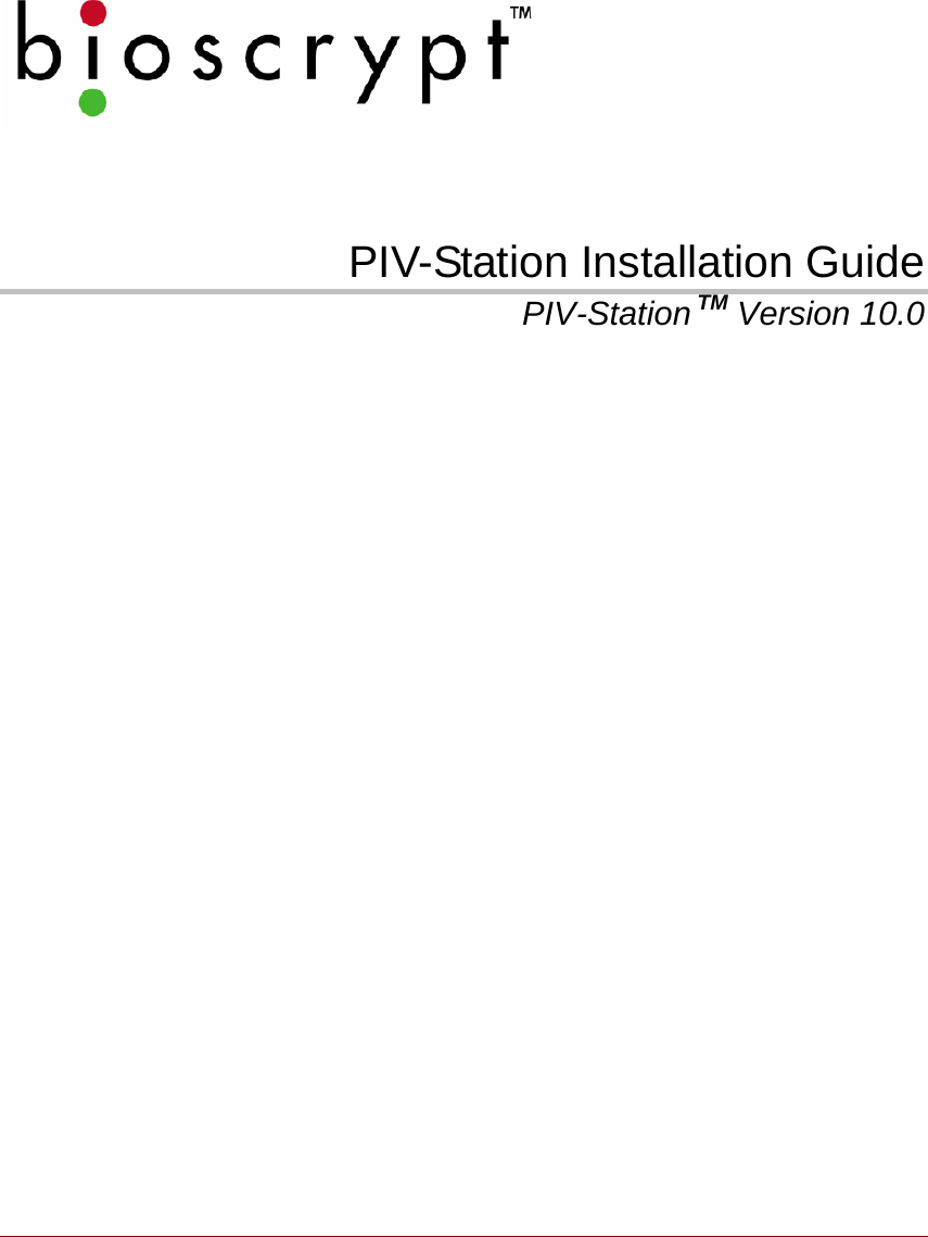
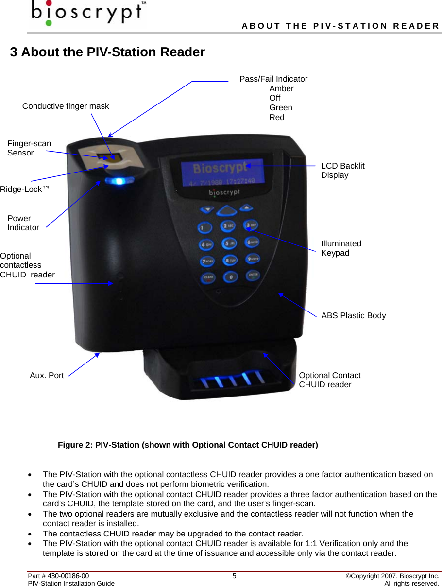
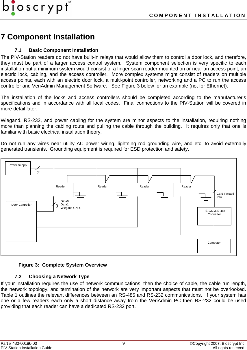
![EARTH GROUND Part # 430-00186-00 ©Copyright 2007, Bioscrypt Inc. PIV-Station Installation Guide All rights reserved. 42 Earth Ground It is extremely critical for proper operation of the Reader that the earth ground be properly connected to avoid damage by ESD. Connect the terminal labeled EGND to earth ground. This wire should not be connected to the neutral, the cable shield, or any other wire except earth ground. See Figure 1 (PIV-Station Contactless CHUID Reader shown) below. • EARTH GROUND: A low impedance path to earth for the purpose of discharging lightning, static, and radiated energy, and to maintain the main service entrance at earth potential. Consult local codes for guidelines. • ESD: Electrostatic Discharge (static electricity). The effects of a static discharge can degrade or destroy semiconductor junctions for an electronic device. Figure 1: Earth Ground Connections Earth Ground To protect reader from ESD EGND connector on unit back Power (+) Power Ground (-) Comment [D1]: Need new picture?](https://usermanual.wiki/Bioscrypt/VSTNUGR/User-Guide-765025-Page-5.png)
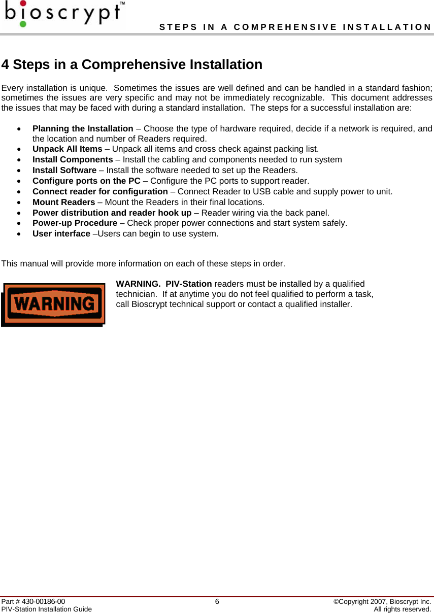
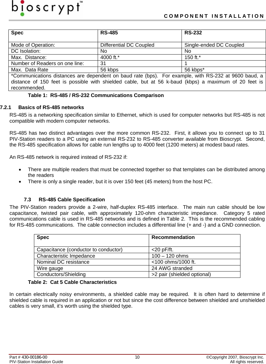
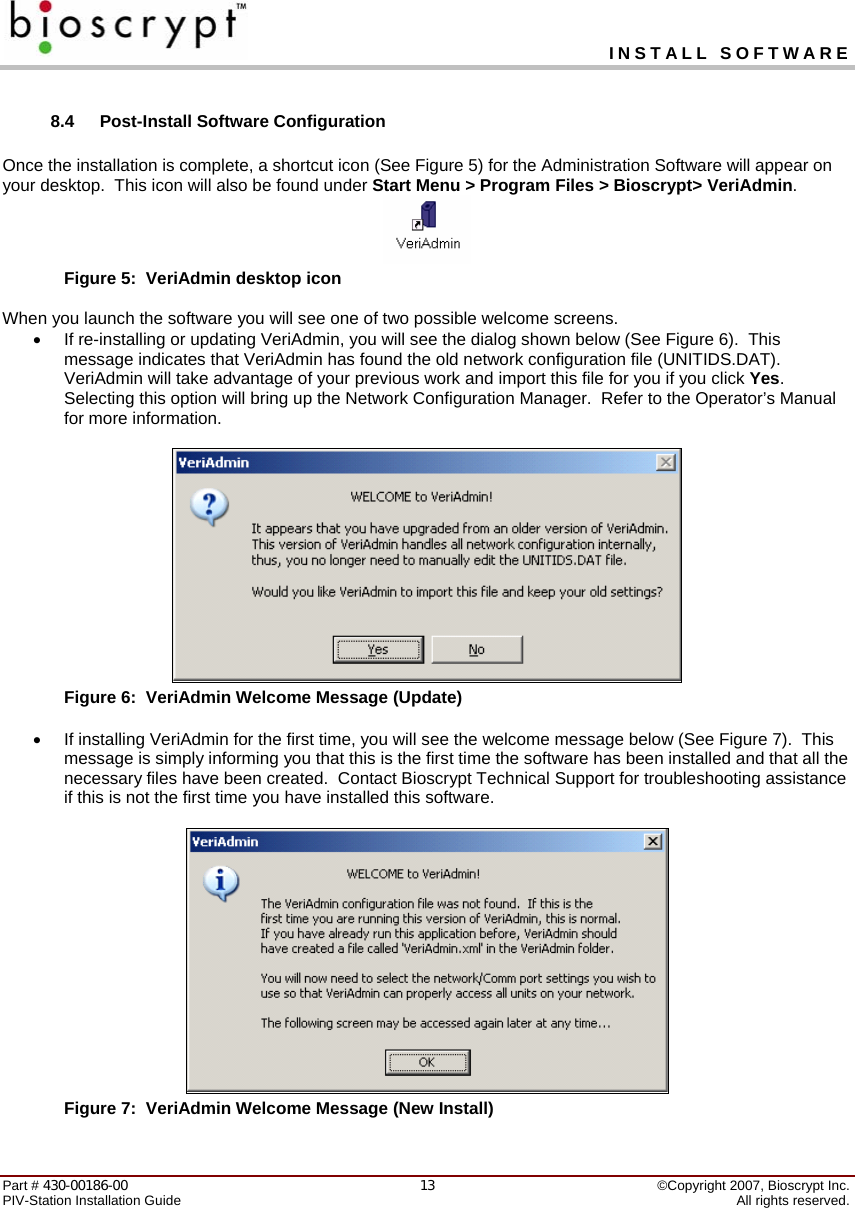
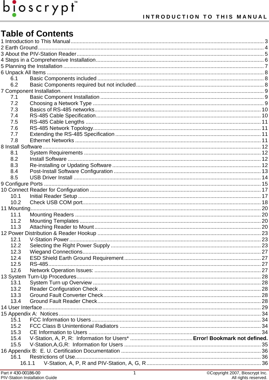
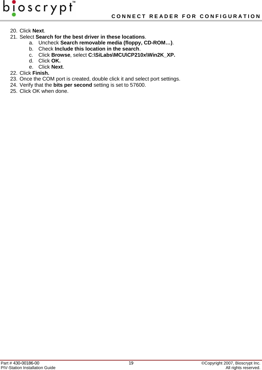
![INSTALL SOFTWARE Part # 430-00186-00 ©Copyright 2007, Bioscrypt Inc. PIV-Station Installation Guide All rights reserved. 148.5 USB Driver Install V-Station products feature a USB interface for the Aux port, utilizing a Serial-to-USB converter (CP210x USB to UART Bridge). In order to use this interface, the proper drivers must be installed. You should install the drivers BEFORE attaching any of the Readers to your computer's USB port for the first time. 1. Log into the PC as any user with Administrative privileges. 2. Locate the folder USB_Driver_CP210x_Bridge on the installation CD. 3. Double-click the file CP210x_VCP_Win2K_XP.exe and follow the prompts in the Wizard. 4. After the driver is installed, later connecting the first Reader to the computer will auto-locate the driver. 5. If the driver is not located you may be prompted to browse to the drivers in folder C:\SiLabs\MCU\CP210x\Win2K_XP. Comment [D2]: Are we fixing this installer in this version?](https://usermanual.wiki/Bioscrypt/VSTNUGR/User-Guide-765025-Page-15.png)
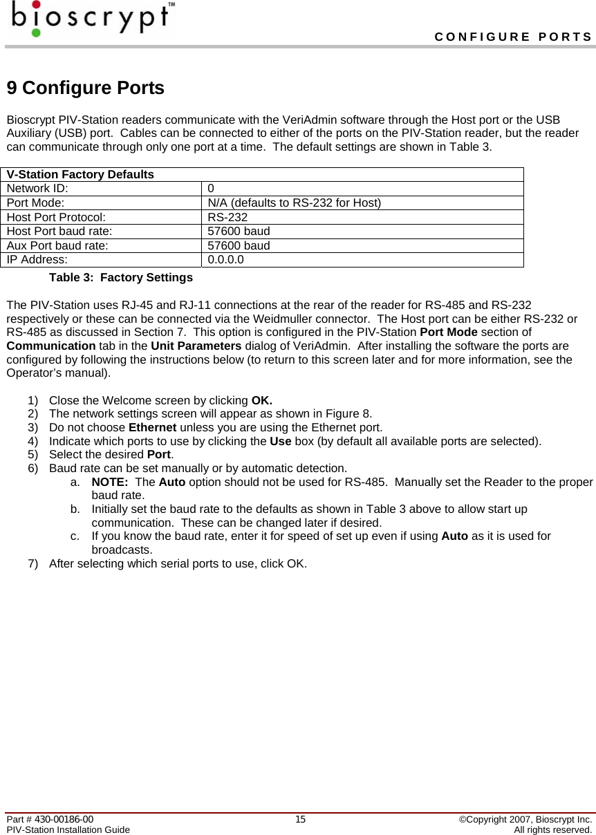
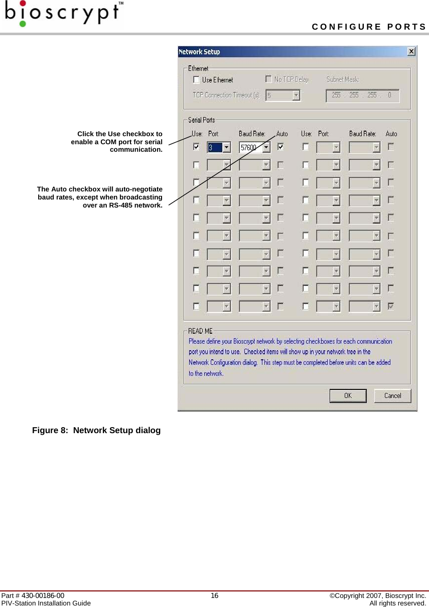
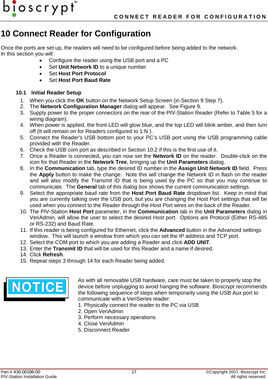
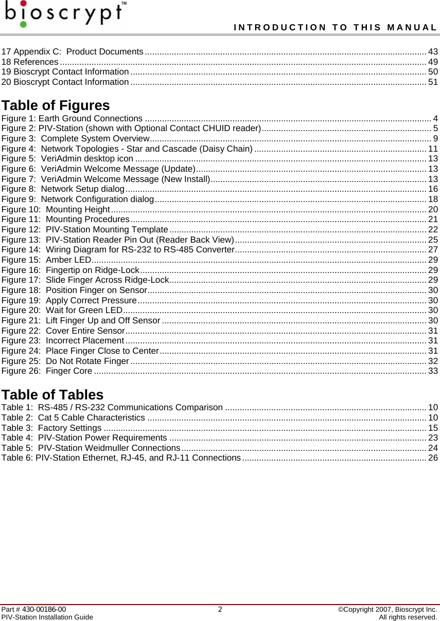
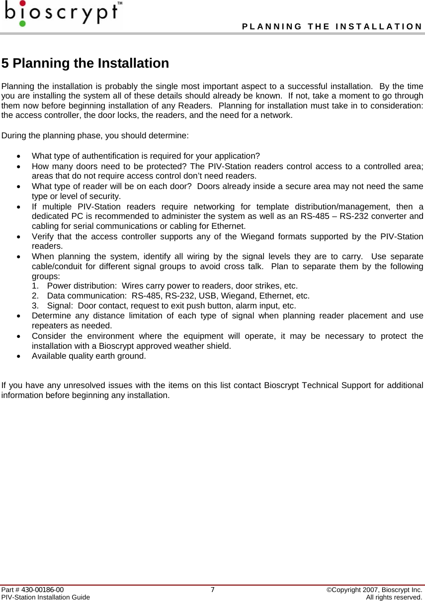
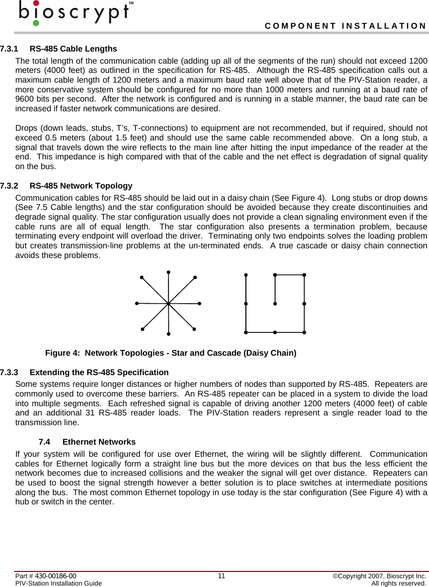
![CONNECT READER FOR CONFIGURATION Part # 430-00186-00 ©Copyright 2007, Bioscrypt Inc. PIV-Station Installation Guide All rights reserved. 18 Figure 9: Network Configuration dialog 10.2 Check USB COM port. 1. Confirm Reader is connected to power. 2. Connect USB cable to reader then connect it to the PC. 3. The new hardware will be found and Add Hardware Wizard will launch. 4. Select No, not at this time then click Next. 5. Select Search for the best driver in these locations. 6. Uncheck Search removable media. 7. Check Include this location in the search - C:\SiLabs\MCU\CP210x\Win2K_XP. 8. Click Next. 9. This will find the driver and install it. 10. The system will find the new hardware again and Add Hardware Wizard will launch. 11. Follow steps 4 to 8 again. 12. Go to Device Manager and confirm COM port number assigned to Reader. 13. If you can locate either of the drivers below skip to Step 23. If not, skip to step 14. a. CP210x USB to UART Bridge Controller [in Ports (COM & LPT)]. b. CP210x USB Composite Device [in Universal Serial Bus Controllers]. 14. Look at the Other Devices category as an Unknown Device. 15. Double-click on the unknown device. 16. Click on the Driver tab. 17. Click Update driver. 18. The Hardware Update Wizard will appear. 19. Select Install from a list or specific location (Advanced).](https://usermanual.wiki/Bioscrypt/VSTNUGR/User-Guide-765025-Page-19.png)
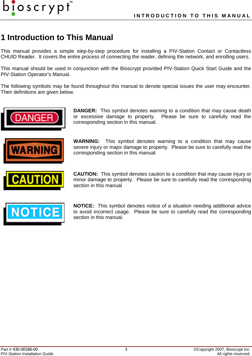
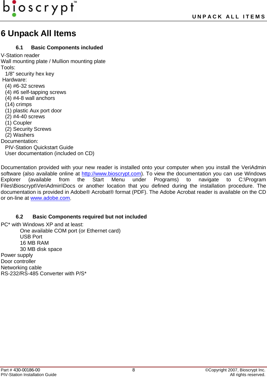
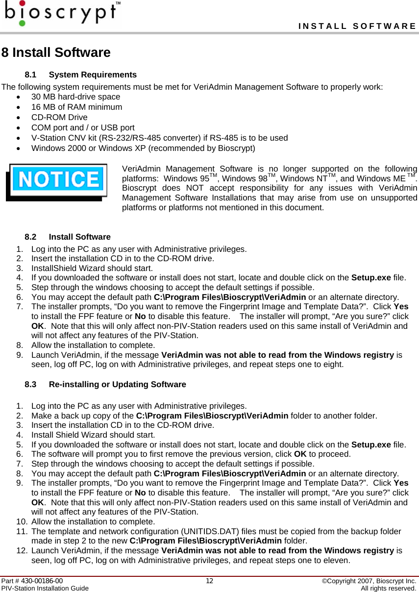
![MOUNTING Part # 430-00186-00 ©Copyright 2007, Bioscrypt Inc. PIV-Station Installation Guide All rights reserved. 22 Figure 12: PIV-Station Mounting Template Comment [D3]: Replace this one with the two for PIV](https://usermanual.wiki/Bioscrypt/VSTNUGR/User-Guide-765025-Page-23.png)
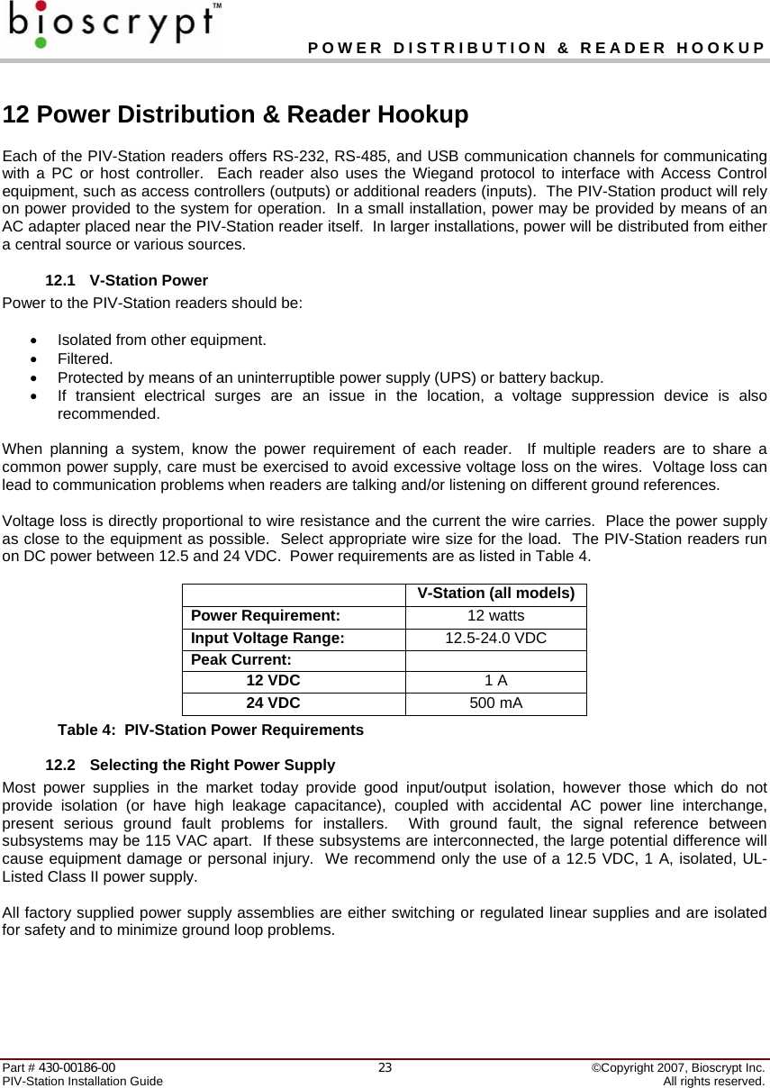
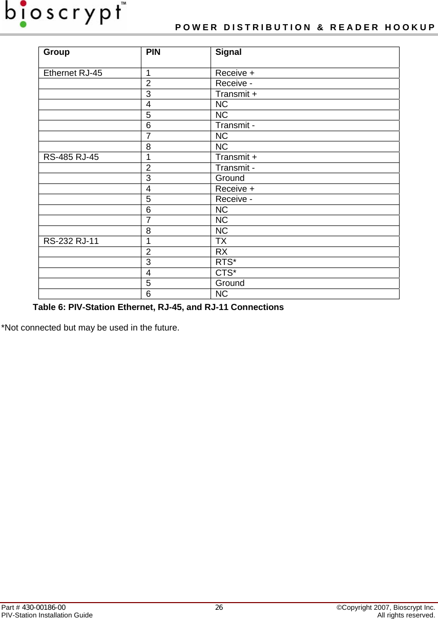
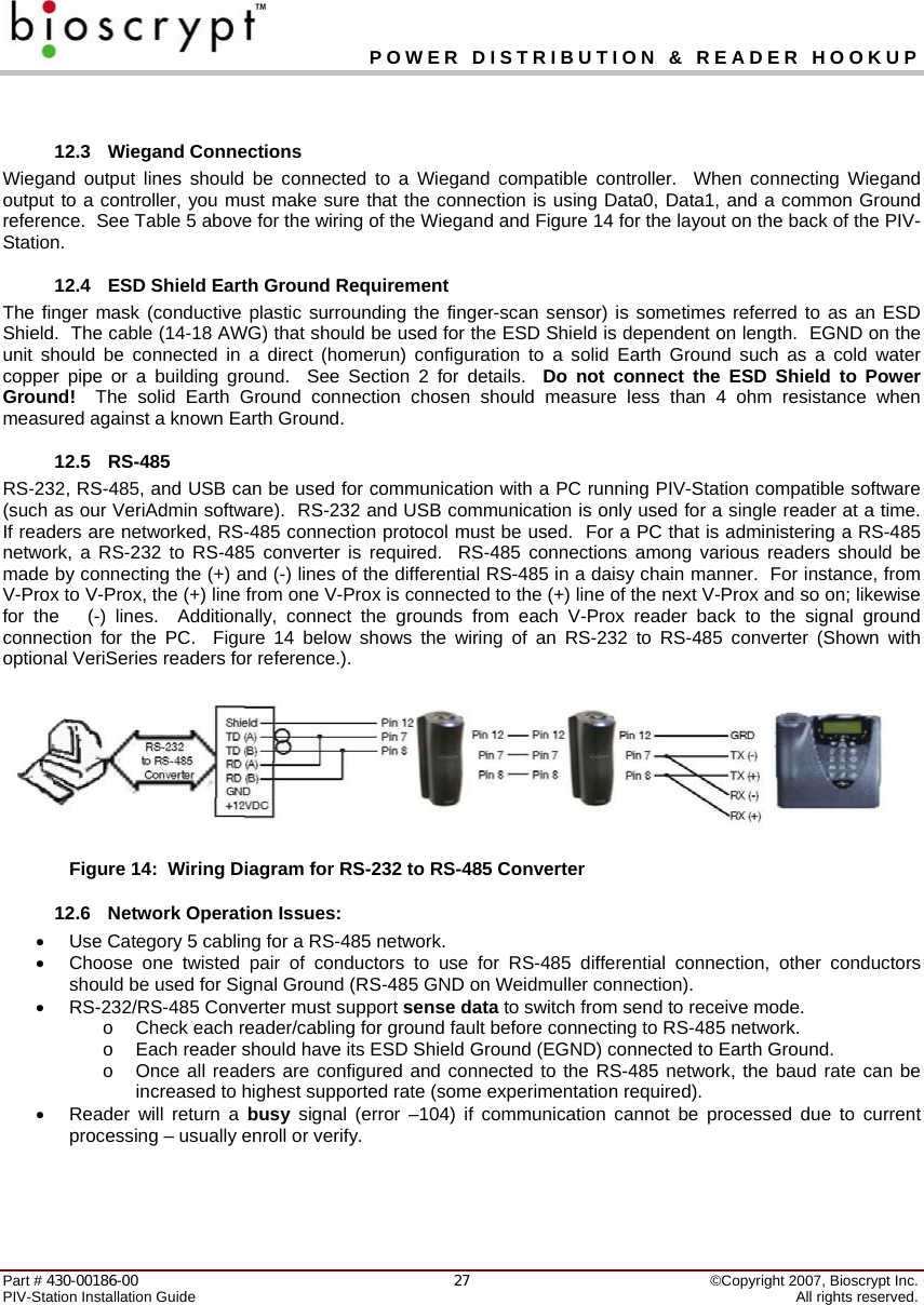
![POWER DISTRIBUTION & READER HOOKUP Part # 430-00186-00 ©Copyright 2007, Bioscrypt Inc. PIV-Station Installation Guide All rights reserved. 24The readers are connected to other components of an integrated system through the rear of the reader. This is made up of the connections described in Table 5. Pin Group Label Signal Description 8-Pin Connector: 1 TX(+) Transmit + 2 TX(-) Transmit - 3 RX(+) Receive + 4 RX(-) Receive - 5 RS-485 GND RS-485 Signal Ground 6 GND RS-232 Signal Ground 7 TX Transmit 8 RS-232 RX Receive 3-Pin Connector: 1 +(POS) 12.5 – 24 VDC + 2 -(NEG) 12.5 – 24 VDC - 3 Power/Ground EGND Earth Ground 12-Pin Connector: 1 IN 0 Data 0 In 2 IN 1 Data 1 In 3 OUT 0 Data 0 Out 4 OUT 1 Data 1 Out 5 LED IN LED In 6 LED OUT LED Out 7 Wiegand GND Wiegand Ground 8 IN 0 TTL Data 0 In 9 TTL (IN) IN 1 TTL Data 1 In 10 Out 0H TTL Data 0 Out 11 OUT 1L TTL Data 1 Out 12 TTL (OUT) GND TTL Ground Table 5: PIV-Station Weidmuller Connections Comment [D4]: Check these.](https://usermanual.wiki/Bioscrypt/VSTNUGR/User-Guide-765025-Page-25.png)
![POWER DISTRIBUTION & READER HOOKUP Part # 430-00186-00 ©Copyright 2007, Bioscrypt Inc. PIV-Station Installation Guide All rights reserved. 25 Figure 13: PIV-Station Reader Pin Out (Reader Back View) Comment [D5]: Needs update?](https://usermanual.wiki/Bioscrypt/VSTNUGR/User-Guide-765025-Page-26.png)
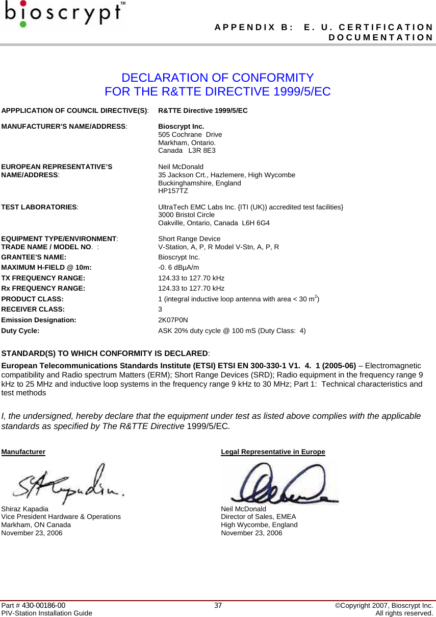
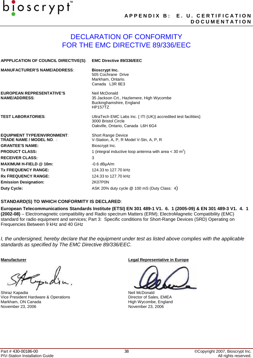
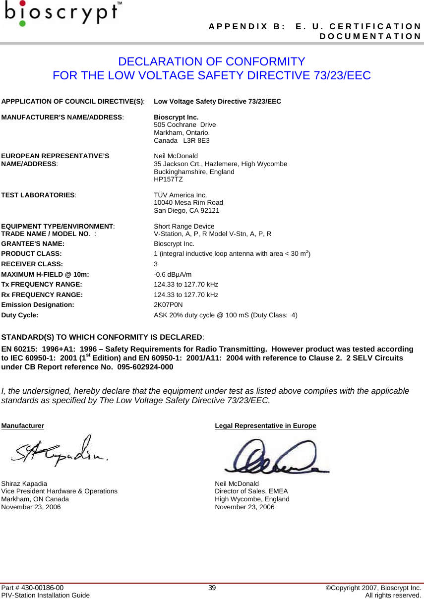
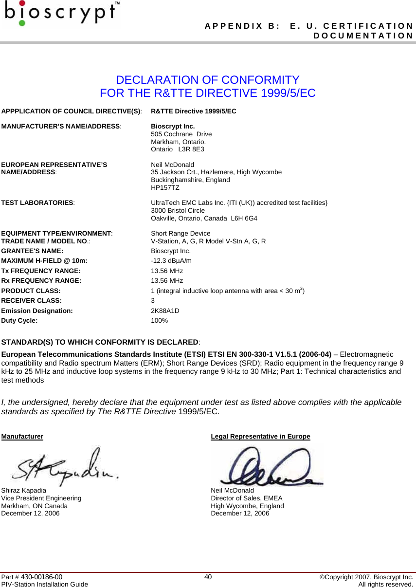
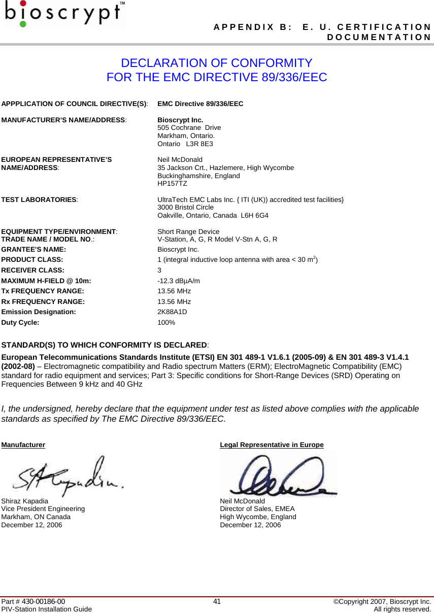
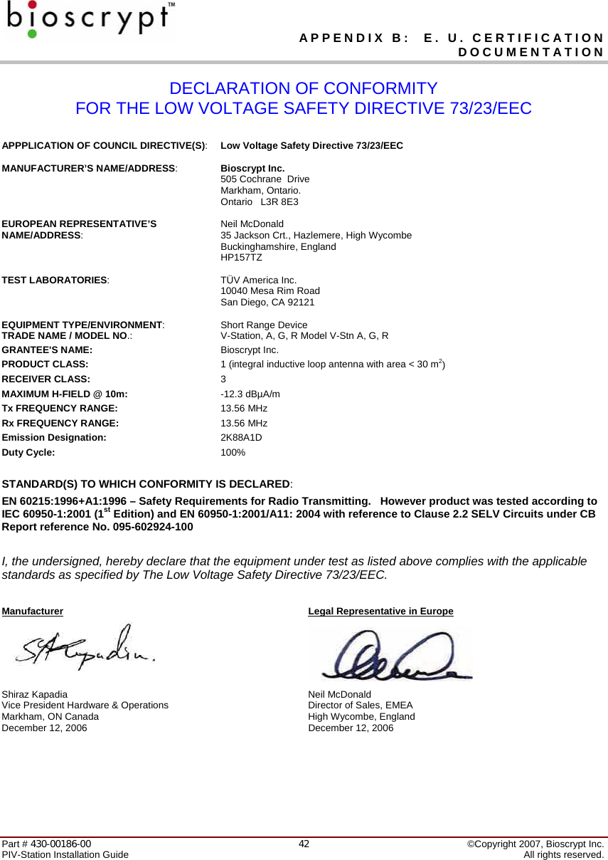
![APPENDIX B: E. U. CERTIFICATION DOCUMENTATION Part # 430-00186-00 ©Copyright 2007, Bioscrypt Inc. PIV-Station Installation Guide All rights reserved. 3616 Appendix B: E. U. Certification Documentation This appendix contains data related to the PIV-Station product line regarding the test procedures and Declarations of Conformity as required under the R&TTE directive by the European Union for all devices containing radio transmitters. The following Bioscrypt products contain radio transmitters: Name Model Number V-STATION, U, G, R V-Stn, U, G, R V-STATION, U, G, GC, R V-Stn, U, G, GC, R Hereby, Bioscrypt declares that the PIV-Station, A, P, R and PIV-Station, A, G, R are in compliance with the essential requirements and other relevant provisions of Directive 1999/5/EC. 16.1 Restrictions of Use 16.1.1 V-Station, U, G, R and PIV-Station, U, GC, R and PIV-Station, U, G, GC, R Bioscrypt has notified and gained approval to sell the PIV-Station, A, P, R and PIV-Station, A, G, R in all EU countries except the ones listed below. There shall be no restrictions of use in all EU countries except the following for the PIV-Station, U, G, R and PIV-Station, U, GC, R and PIV-Station, U, G, GC, R readers: • Bulgaria • Croatia • Romania For latest product approval status and updates, please refer to the Bioscrypt web page at: http://www.bioscrypt.com. Comment [D6]: Update this section Comment [D7]: Update model numbers](https://usermanual.wiki/Bioscrypt/VSTNUGR/User-Guide-765025-Page-37.png)
![APPENDIX C: PRODUCT DOCUMENTS Part # 430-00186-00 ©Copyright 2007, Bioscrypt Inc. PIV-Station Installation Guide All rights reserved. 48C.5 Important Note Regarding UL 294 PIV-Station Information for Users These Readers are intended to be used with Listed (UL 294) control equipment as specified in the control unit manufacturer's installation/operation documents. The PIV-Station, U, G, R and PIV-Station, U, GC, R and PIV-Station, U, G, GC, R shall comply with the standard for Access Control System Units for UL294 and with CSA C22.2 No. 205 for the cUL mark. If using Ethernet as the primary communications port, the product shall comply with UL294 if, and only if, the user installs the specified Ethernet Coupler part (Bioscrypt part number 668-00135-00R). This part shall be packaged with any PIV-Station, U, G, R or PIV-Station, U, GC, R or PIV-Station, U, G, GC, R product. V-Station battery Information DANGER! RISK OF EXPLOSION IF BATTERY IS REPLACED BY AN INCORRECT TYPE. DISPOSE OF USED BATTERIES ACCORDING TO LOCAL ORDINANCES. This equipment is provided with a replaceable battery and replacement by an incorrect type may result in an explosion. Note: These batteries are not field replaceable. If replacement is required, this Reader should be returned to Bioscrypt Service for replacement of the battery. Comment [D8]: Update model numbrs.](https://usermanual.wiki/Bioscrypt/VSTNUGR/User-Guide-765025-Page-49.png)