Biostar 865Gv Micro 775 Owners Manual I865GM7A_V8x_+I86GVM7_1027C
2014-07-31
: Biostar Biostar-865Gv-Micro-775-Owners-Manual biostar-865gv-micro-775-owners-manual biostar pdf
Open the PDF directly: View PDF ![]() .
.
Page Count: 85

865G Mirco 775 / 865GV Micro 775
Setup Manual
FCC Information and Copyright
This equipment has been tested and found to comply with the limits of a Class
B digital device, pursuant to Part 15 of the FCC Rules. These limits are designed
to provide reasonable protec tion against harmful interference in a residential
installation. This equipment generates, uses and can radiate radio frequency
energy and, if not installed and used in accordance with the instructions, may
cause harmful interference to radio communications. There is no guarantee
that interference will not occur in a particular ins talla tion.
The ve ndor makes no representatio ns or warranties with respec t to the
contents here and specially disclaims any implied warranties of merchantability
o r fi tness fo r a ny purpos e . F u rthe r t he ve ndo r rese rves t he ri ght to rev ise t his
publication and to make changes to the contents here without obligation to
notify any party beforehand.
D uplica tion of this publication, in part or in whole, is not allowed without first
obtaining the vendor’s approval in writing.
The content of this user’s manual is subject to be changed without notice and
we will not be res ponsible for any mistakes found in this user’s manual. All the
brand and product names are trademarks of their respective companies.

Table of Contents
Chapter 1: Introduction .............................................1
1.1 Before You Start...................................................................1
1.2 Package Checklist................................................................1
1.3 Motherboard Features.......................................................... 2
1.4 Rear Panel Connectors..........................................................3
1.5 Motherboard Layout of 865G Micro 775..................................4
1.6 Motherboard Layout of 865GV Micro 775................................ 5
Chapter 2: Hardware Installation..............................6
2.1 Installing Central Processing Unit (CPU)................................6
2.2 FAN Headers........................................................................8
2.3 Installing System Memory......................................................9
2.4 Connectors and Slots............................................................11
Chapter 3: Headers & Jumpers Setup .....................14
3.1 How to Setup Jumpers..........................................................14
3.2 Detail Settings.....................................................................14
Chapter 4: Useful Help .............................................20
4.1 Driver Installation Note .......................................................20
4.2 Award BIOS Beep Code........................................................21
4.3 Extra Information................................................................21
4.4 Troubleshooting...................................................................23
Chapter 5: WarpSpeeder™ .......................................24
5.1 Introduction........................................................................24
5.2 System Requirement............................................................24
5.3 Installation.........................................................................25
5.4 WarpSpeeder™....................................................................26
Appendencies: SPEC In Other Language ................32
German................................................................................................32
France..................................................................................................34
Italian..................................................................................................36
Spanish................................................................................................38
Portuguese...........................................................................................40
Polish...................................................................................................42
RUSSIAN...............................................................................................44
ARABIC................................................................................................46
JAPANESE............................................................................................48

865G Micro 775 & 865GV Micro 775
1
CHAPTER 1: INTRODUCTION
1.1 BEFORE YOU START
Tha nk yo u for choosing our pro duct. Be fore you start installing the
mo the rboa rd, plea se make sure you fo llow the instructions be lo w:
Prepare a dry and stable working environment with
s ufficie nt ligh ting .
Always disconnect the computer from power outlet
be fo re ope ra tion.
Befo re you take the mo the rboa rd ou t f rom a n ti -s ta tic
bag, ground yourself properly by touching any safely
grounde d appliance, o r use gro unded wrist strap to
remove the static charge.
Avo id tou ch ing the compone nts o n mo the rboa rd o r the
rear side of the board unless necessary. Hold the board
on the edge, do not try to be nd or flex the board.
Do not leave any unfastene d sma ll parts inside the
case after installation. Loose parts will cause short
circuits which ma y damage the equipment.
Keep the computer from dangerous area, such as heat
source , humid air and wa te r.
1.2 PACKAGE CHECKLIST
FDD Cable X 1
HDD Cable X 1
Rear I/O Panel for ATX Case X 1
Use r’s Manual X 1
Fully Setup Driver CD X 1
Se ria l ATA Cab le X 1 (op tiona l)
Se ria l ATA Po we r Cab le X 1 (o ptio nal)
USB 2.0 Cable X1 (optional)
S/P DI F ou t Ca ble X 1 (op tiona l)

Motherboard Manual
2
1.3 MOTHERBOARD FEATURES
865G Micro 775 865GV Micro 775
CPU
LGA 775
Intel Pentium 4 / Pentium D / Celeron D
processor up to 3.4 GHz
Intel Core2Duo Processor (For Ver 8.x only)
Supports Hyper-Threading
Execute Disable Bit
Enhanced Intel SpeedStep
Extended Memory 64 Technology
LGA 775
Intel Pentium 4 / Pentium D / Celeron D
processor up to 3.4 GHz
Supports Hyper-Threading
Execute Disable Bit
Enhanced Intel SpeedStep
Extended Memory 64 Technology
FSB 533 / 800 MHz 533 / 800 MHz
Chipset Intel 865G
Intel ICH5
Intel 865GV
Intel ICH5
Graphics Intel Extreme Graphics 2
Max Shared Video Memory is 64MB
Intel Extreme Graphics 2
Max Shared Video Memory is 64MB
Super I/O
ITE IT8712F
H/W Monitor
Fan Speed Controller
ITE's "Smart Guardian" function
ITE IT8712F
H/W Monitor
Fan Speed Controller
ITE's "Smart Guardian" function
Main
Memory
DIMM Slots x 2
Eac h DIMM supports 128/256/512MB & 1GB
DDR
Max Memory Capicity 2GB
Dual Channel Mode DDR memory module
Supports DDR 266 / 333 / 400
DIMM Slots x 2
Eac h DIMM supports 128/256/512MB & 1GB
DDR
Max Memory Capicity 2GB
Dual Channel Mode DDR memory module
Supports DDR 266 / 333 / 400
IDE
Integrated IDE Controller
Ultra DMA 33~100 Bus Master Mode
supports PIO Mode 0~4,
Integrated IDE Controller
Ultra DMA 33~100 Bus Master Mode
supports PIO Mode 0~4,
SA TA
Integrated Serial ATA Controller
Data transfer rates up to 1.5 Gb/s.
SATA Version 1.0 specification compliant.
Integrated Serial ATA Controller
Data transfer rates up to 1.5 Gb/s.
SATA Version 1.0 specification compliant.
10/100 LAN
Realtek RTL 8100C
10 / 100 Mb/s auto negotiation
Half / Full duplex capability
Realtek RTL 8100C
10 / 100 Mb/s auto negotiation
Half / Full duplex capability
Sound
Codec
ALC655 / 658
5.1 channels audio out
AC’97 Vers ion 2.3
ALC655 / 658
5.1 channels audio out
AC’97 Vers ion 2.3
AGP 8X graphics slot x1 XGP graphics slot x1
Slots PCI s lot x3 PCI s lot x3
865G Micro 775 & 865GV Micro 775
3
865G Micro 775 865GV Micro 775
Floppy connector x1 Floppy connector x1
IDE Connector x2 IDE Connector x2
SA TA C onnect or x2 SATA C onnect or x2
Front Panel Connector x1 Front Panel Connector x1
Front Audio Connector x1 Front Audio Connector x1
CD-in Connec tor x1 CD-in Connec tor x1
S/PDIF in connector (optional) x1 S/PDIF in connector (optional) x1
S/PDIF out connector x1 S/PDIF out connector x1
CPU Fan header x1 CPU Fan header x1
Sys tem Fan header x1 Sys tem Fan header x1
Clear CMOS header x1 Clear CMOS header x1
USB connector x2 USB connector x2
Power Connector (20pin) x1 Power Connector (20pin) x1
On Board
Connector
Power Connector (4pin) x1 Power Connector (4pin) x1
Back Panel
I/O
PS/2 Keyboard x1
PS/2 Mouse x1
S e ri a l Po rt x 1
Printer Port x1
VGA port x1
LAN port x1
USB Port x4
Audio Jack x3
PS/2 Keyboard x1
PS/2 Mouse x1
S e ri a l Po rt x 1
Printer Port x1
VGA port x1
LAN port x1
USB Port x4
Audio Jack x3
Board Size 215 (W) x 235 (L) mm 215 (W) x 235 (L) mm
OS Support
Windows 2000 / XP
Biostar Reserves the right to add or remove
support for any OS with or without notice.
Windows 2000 / XP
Biostar Reserves the right to add or remove
support for any OS with or without notice.
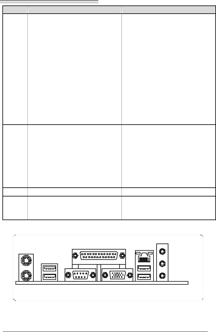
1.4 REAR PANEL CONNECTORS
VGA1
PS/2
Mouse
PS/ 2
Ke yboard
Printer Port
COM1 USBX2USBX2
LAN Line In/
Su rround
Line Out
Mic I n 1/
Bass/ Center
Motherboard Manual
4
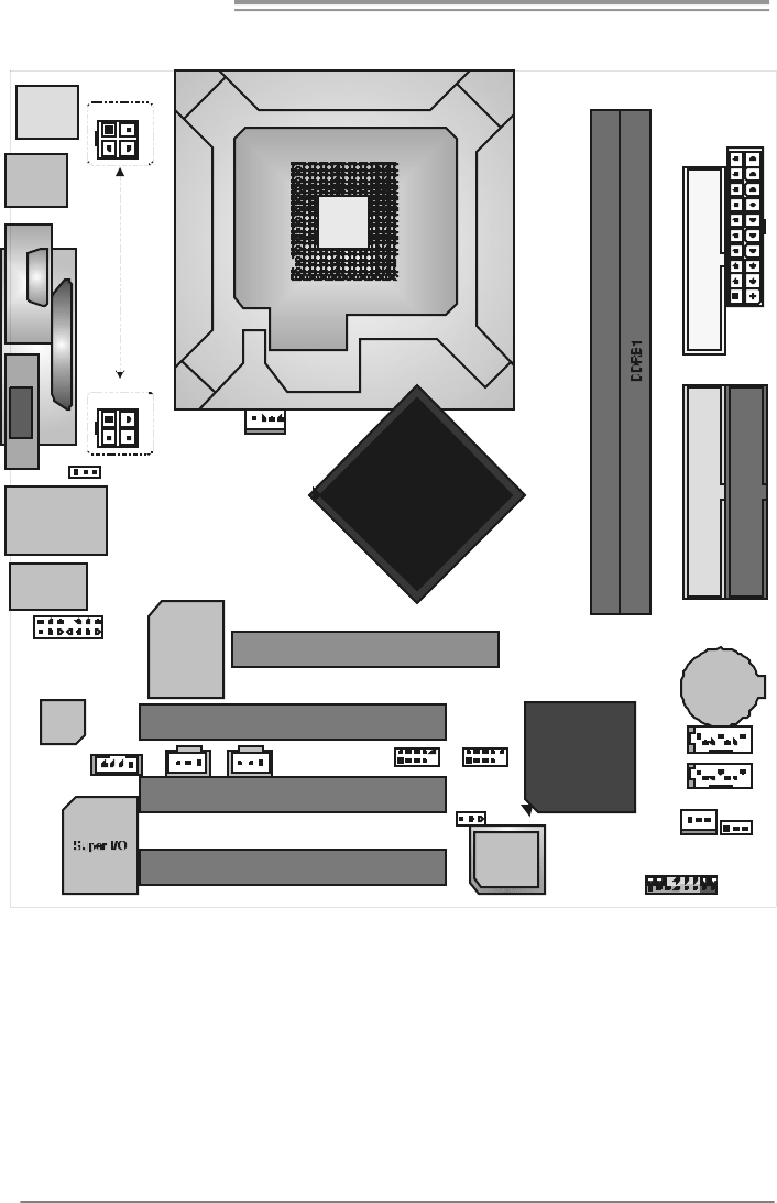
1.5 MOTHERBOARD LAYOUT OF 865G MICRO 775
LGA775
CP U1
COM1
JPRNT1
JC OM1
BIO S
ICH5
Code c
A
GP1
PCI1
PC I2
PC I3
SATA2
SATA1
JSFAN1
LAN
JATXPWR1
JC FAN 1
J US BV3
_
4
(
o
p
tional
)
JU S B3JU S B2
JCDIN1
JAUDIO2
JKBMS1
JUSB1
JATX PWR 2
JA U D IO 1
JVGA1
JUSBLAN1
J U SB V2
(optional)
JS PD IF _OU T 1
DD RA1
Intel
865G
J PAN EL1
JCMOS1
(Optional)
JSPDIF_IN1
BAT1
IDE2
IDE1
FD D1
JATX PWR 2
(Fo r all the other versions.)
(For Ver. 8.x.)
Note: represents the 1■st pin.
865G Micro 775 & 865GV Micro 775
5
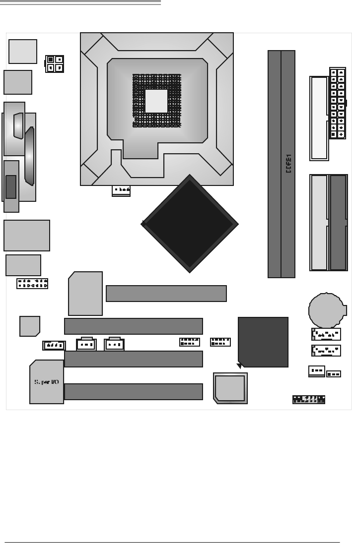
1.6 MOTHERBOARD LAYOUT OF 865GV MICRO 775
LGA775
CP U1
COM1
JPRNT1
JC OM1
BIO S
ICH5
Code c
XGP1
PCI1
PC I2
PC I3
SATA2
SATA1
JSFAN1
LAN
JATXPWR1
JC FAN 1
JU S B3JU S B2
JCDIN1
JAUDIO2
JKBMS1
JUSB1
JATX PWR 2
JA U D IO 1
JVGA1
JUSBLAN1
JS PD IF _OU T 1
DD RA1
Intel
865GV
J PAN EL1
JCMOS1
(Optional)
JSPDIF_IN1
BAT1
IDE2
IDE1
FD D1
Note: represents the 1■st pin.
Motherboard Manual
6
CHAPTER 2: HARDWARE INSTALLATION
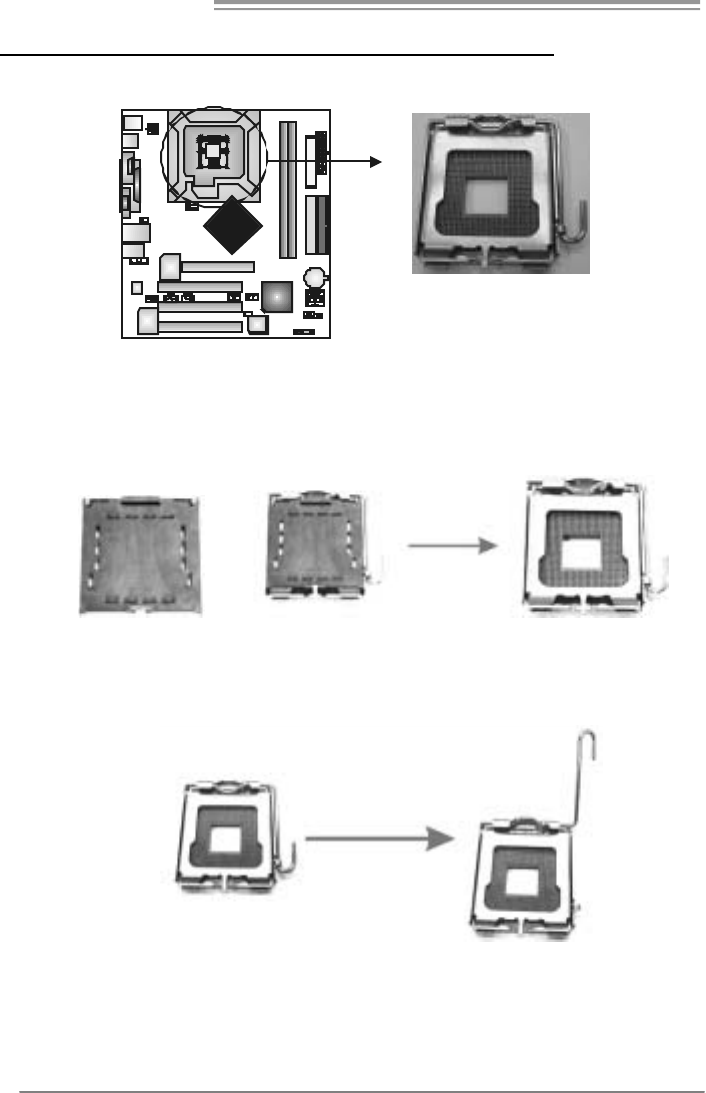
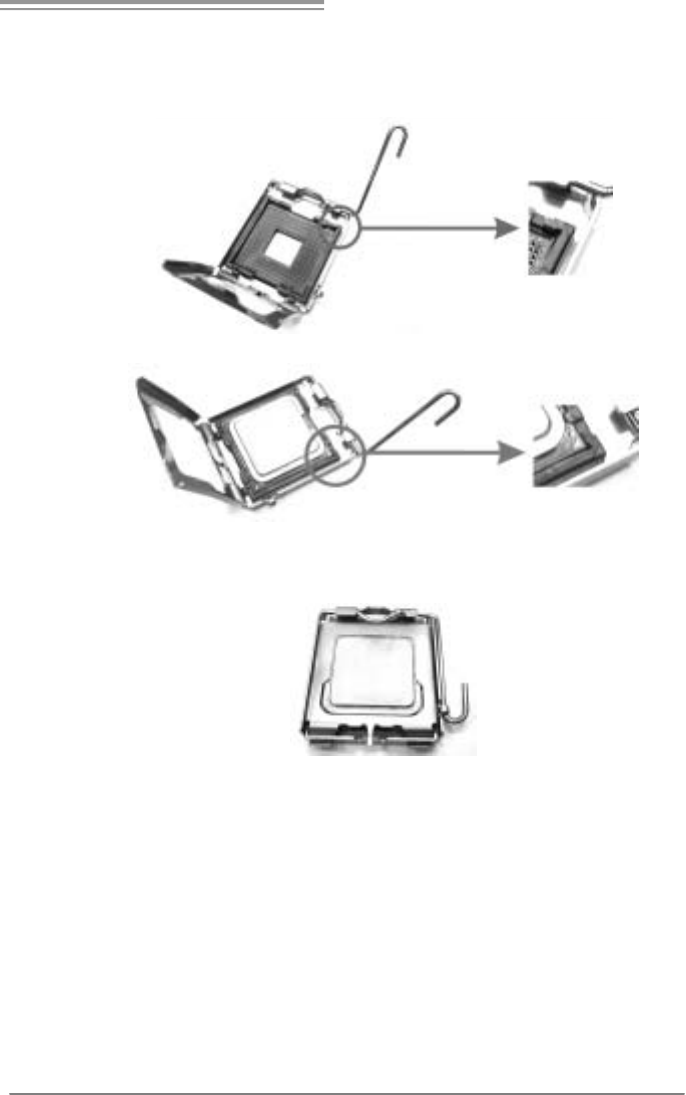
2.1 INSTALLING CENTRAL PROCESSING UNIT (CPU)
Special Notice:
Remove Pin Cap before installation, and make good preservation
for future use. When the CPU is removed, cover the Pin Cap on the
empty socket to ensure pin legs won’t be damaged.
Pin Cap
Step 1: Pull the socket locking lever out from the socket and then raise
the lever up to a 90-degree angle.
865G Micro 775 & 865GV Micro 775
7
Step 2: Look for the triangular cut edge on socket, and the golden dot on
CPU should point forwards this triangular cut edge. The CPU will
fit only in the correct orientation.
Step 2-1:
Step 2-2:
Step 3: Hold the CPU down firmly, and then lower the lever to locked
position to complete the installation.
Step 4: Put the CPU Fan and heatsink assembly on the CPU and buckle it
on the retention frame. Connect the CPU FAN power cable into
the JCFAN1. This completes the installation.
Motherboard Manual
8
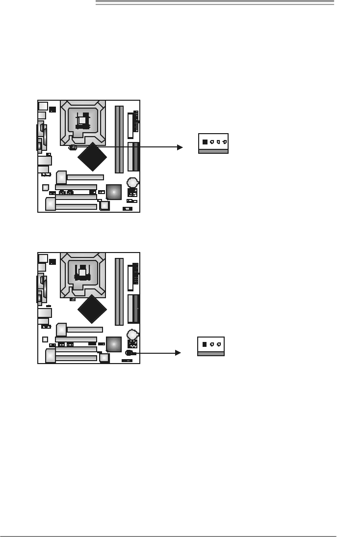
2.2 FAN HEADERS
These fan headers support cooling-fans built in the computer. The fan
cable and connector may be different according to the fan manufacturer.
Connect the fan cable to the connector while matching the black wire to
pin#1.
JCFAN1: CPU Fan Header
Pin
Assignment
1 Ground
2 +12V
3 FAN RPM rate
sense
JCFAN1
14
4 Smart Fan
Control
JSFAN1: System Fan Header
Pin
Assignment
1 Ground
2 +12V
JSFAN1
13
3 FAN RPM rate
sense
Note:
The JSFAN1 s upport 3-pi n head connec tor. When c onnecti ng with wires ont o connec tors,
pleas e note that t he red wire is t he positi ve and s hould be con nect ed to pin#2, and t he
blac k wire is Ground and s hould be c onnect ed to GND.
865G Micro 775 & 865GV Micro 775
9
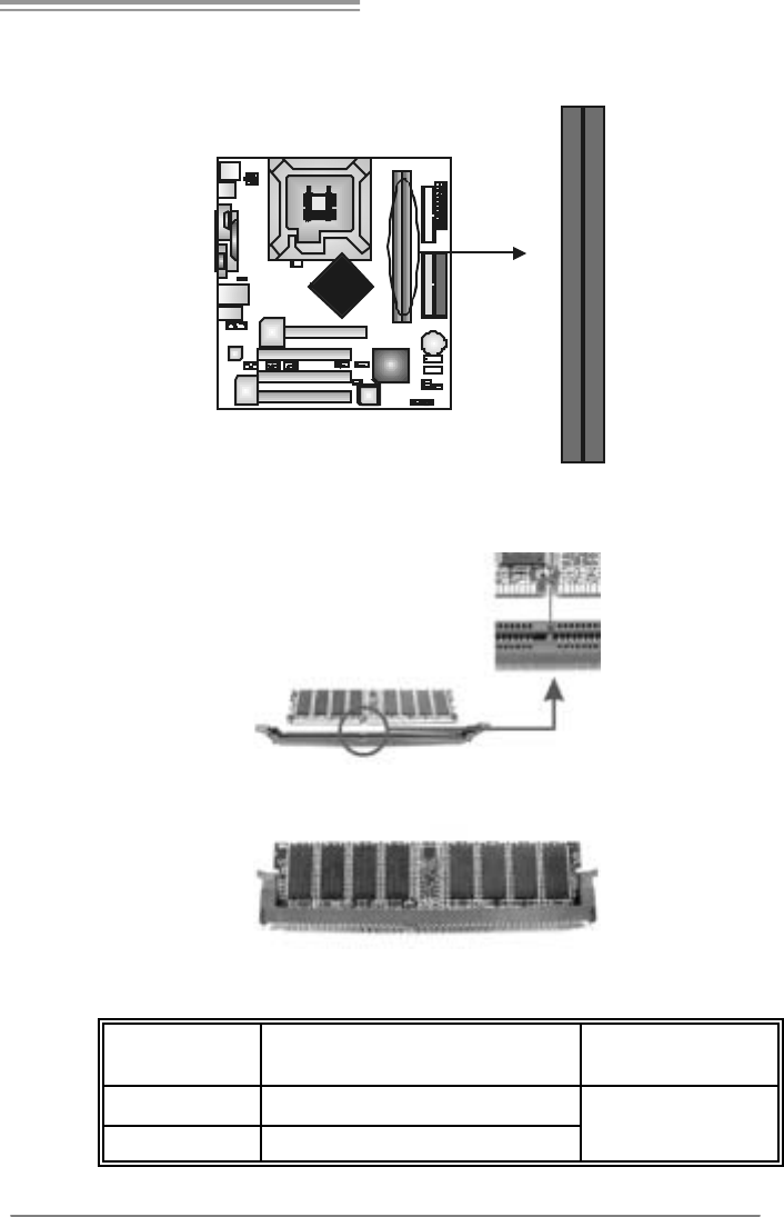
2.3 INSTALLING SYSTEM MEMORY
A. Memory Modules
DDRB1
DDRA1
1. Unlock a DIMM slot by pressing the retaining clips outward. Align a
DIMM on the slot such that the notch on the DIMM matches the
break on the Slot.
2. Insert the DIMM vertically and firmly into the slot until the retaining
chip snap back in place and the DIMM is properly seated.
B. Memory Capacity
DIMM Socket
Location DDR Module Total Memory Size
DDRA1 256MB/512MB/1GB *1
DDRB1 256MB/512MB/1GB *1 Max is 2GB.

Motherboard Manual
10
C. Dual Channel Memory installation
To trigger the Dual Channel f unction of the motherboard, the memory module
must meet the following requirements:
Install memory module of the same density in pair, shown in the following table.
Dual Channel Status DDRA1 DDRB1
Disabled O X
Disabled X O
Enabled O O
(O means memory installed, X means memory not installed.)
The DRAM bus width of the memory module must be the same (x8 or
x16)
865G Micro 775 & 865GV Micro 775
11
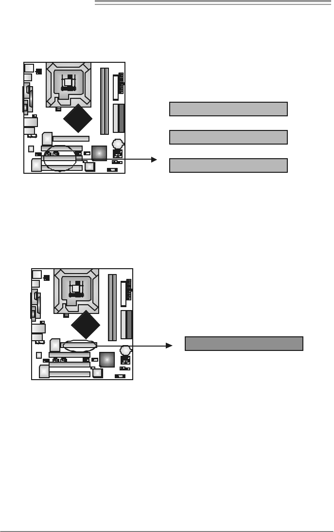
2.4 CONNECTORS AND SLOTS
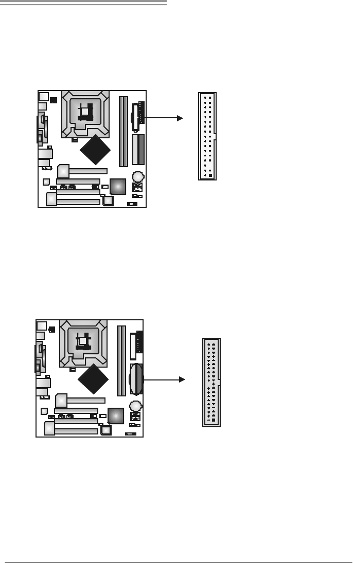
FDD1: Floppy Disk Connector
The motherboard prov ides a standard floppy disk connector that supports 360K,
720K, 1.2M, 1.44M and 2.88M floppy disk ty pes. This connector supports the
prov ided f loppy drive ribbon cables.
34 33
12
IDE1/IDE2: Hard Disk Connectors
The motherboard has a 32-bit Enhanced PCI IDE Controller that prov ides PIO
Mode 0~4, Bus Master, and Ultra DMA 33/66/100 functionality. It has two HDD
connectors IDE1 (primary) and IDE2 (secondary).
The IDE connectors can connect a master and a slav e driv e, so you can
connect up to four hard disk drives. The f irst hard drive should always be
connected to IDE1.
IDE2 IDE1
21
3940
Motherboard Manual
12
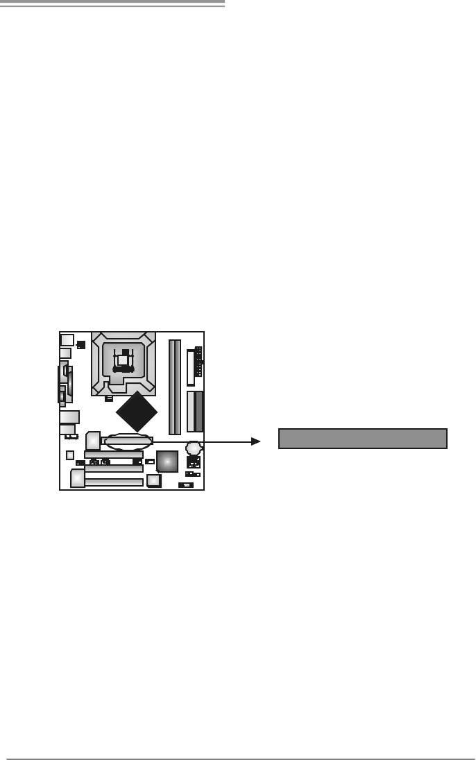
PCI1~PCI3: Peripheral Component Interconnect Slots
This motherboard is equipped with 3 standard PCI slots. PCI stands f or
Peripheral Component Interconnect, and it is a bus standard for expansion
cards. This PCI slot is designated as 32 bits.
PCI3
PCI2
PCI1
AGP1: Accelerated Graphics Port Slot ( 865G Micro 775 only )
Your monitor will attach directly to that video card. This motherboard supports
video cards for PCI slots, but it is also equipped with an Accelerated Graphics
Port (AGP). An AGP card will take adv antage of AGP technology for improv ed
video efficiency and perf ormance, especially with 3D graphics.
A
GP
865G Micro 775 & 865GV Micro 775
13
XGP1: Xtreme Graphics Port Slot ( 865GV Micro 775 only )
This XGP (Extreme Graphics Port) slot is a special design that only supports
compatible AGP VGA cards.
To install the system with an add-on AGP VGA card, please make sure to install
the driver of add-on AGP VGA card before onboard VGA driv er installation. If the
onboard VGA driver has already been installed bef ore you install the add-on
AGP VGA card, the system will automatically set the onboard VGA as the
primary graphics adapter.
For the onboard VGA driver can’t be remov ed completely, and to solv e this
problem, please follow the steps below,
1. Disable onboard VGA utility under the operating system, and reboot PC. After
PC restarts, the system will automatically set the AGP VGA card as the
graphics adapter.
2. Or, re-install your operating system to ensure the AGP VGA card function can
be used.
Note:
Please go to “http://www.biostar.com.tw” for more detailed information about
XGP compatible AGP cards.
XGP
Motherboard Manual
14
CHAPTER 3: HEADERS & JUMPERS SETUP
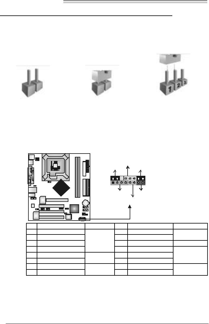
3.1 HOW TO SET UP JUMPERS
The illustration shows how to set up jumpers. When the jumper cap is
placed on pins, the jumper is “close”, if not, that means the jumper is
“open”.
Pin opened Pin closed Pin1-2 closed
3.2 DETAIL SETT INGS
JPANEL1: Front Panel Header
This 16-pin connector includes Power-on, Reset, HDD LED, Power LED, Sleep
button and speaker connection. It allows user to connect the PC case’s f ront
panel switch functions.
1
9
8
16
SLP PW R
_
LED
On/Off
RST
HLED
SPK
++
+
-
-
Pin Assignment Function Pin Assignment Function
1 +5V 9 Sleep control
2 N/A 10 Ground Sleep button
3 N/A 11 N/A N/A
4 Speaker
Speaker
Connector
12 Power LED (+)
5 HDD LED (+) 13 Power LED (+)
6 HDD LED (-)
Hard drive
LED 14 Power LED (-)
Power LED
7 Ground 15 Power button
8 Reset control Reset button 16 Ground Power-on button
865G Micro 775 & 865GV Micro 775
15
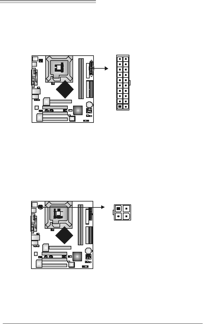
JATXPWR1: ATX Powe r S ou rce C onne ctor
This connector allows user to connect 20-pin power connector on the ATX
power supply.
Pin Assignment
1 +3.3V
2 +3.3V
3 Ground
4 +5V
5 Ground
6 +5V
7 Ground
8 PW_OK
9 Standby Voltage
+5V
10 +12V
11 +3 . 3 V
12 -12V
13 Ground
14 PS_ON
15 Ground
16 Ground
17 Ground
18 -5V
19 +5V
1
10
11
20
20 +5V
JATXPWR2: ATX Powe r S ou rce C onne ctor
By connecting this connector, it will provide +12V to CPU power circuit.
Pin
Assignment
1 +12V
2 +12V
3 Ground
13
24
4 Ground
Motherboard Manual
16
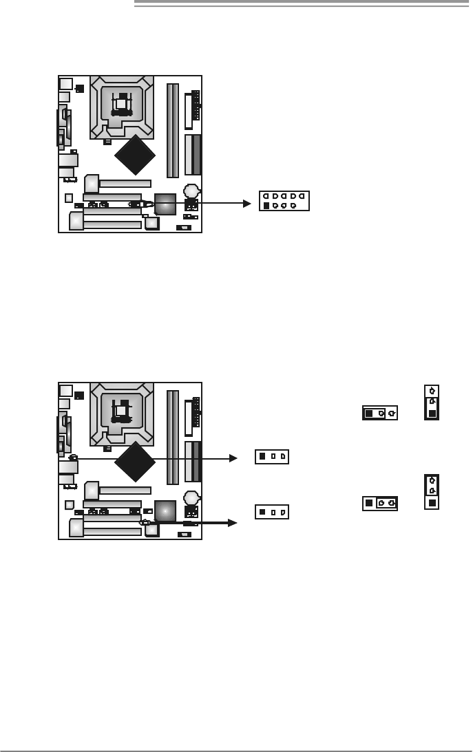
JUSB2/JUSB3: Headers for USB 2.0 Ports at Front Panel
This header allows user to connect additional USB cable on the PC f ront panel,
and also can be connected with internal USB devices, like USB card reader.
Pin
Assignment
1 +5V (fused)
2 +5V (fused)
3 USB-
4 USB-
5 USB+
6 USB+
7 Ground
8 Ground
9 Key
1
2
9
10
JUSB2 JUSB3
10 NC
JUSB V2/JUSBV3_4: Powe r Source Heade rs for USB Ports
(Optional for 865G Micro 775)
Pin 1-2 Close:
JUSBV2/JUSBV3_4: +5V f or USB ports at front panel (JUSB2/JUSB3).
Pin 2-3 Close:
JUSBV2/JUSBV3_4: USB ports at front panel (JUSB2/JUSB3) are powered
by +5V standby voltage.
31
1
3
Pin 1-2 close
JUSBV2
13
JUSBV3_4
13
3
1
1
3
Pin 2-3 close
Note:
In order to support this f unc tion “Power-On s ys tem via U SB device,
“JUSBV2/JUSBV3_4” jumper cap shoul d be pl aced on Pin 2-3 i ndi viduall y.
865G Micro 775 & 865GV Micro 775
17
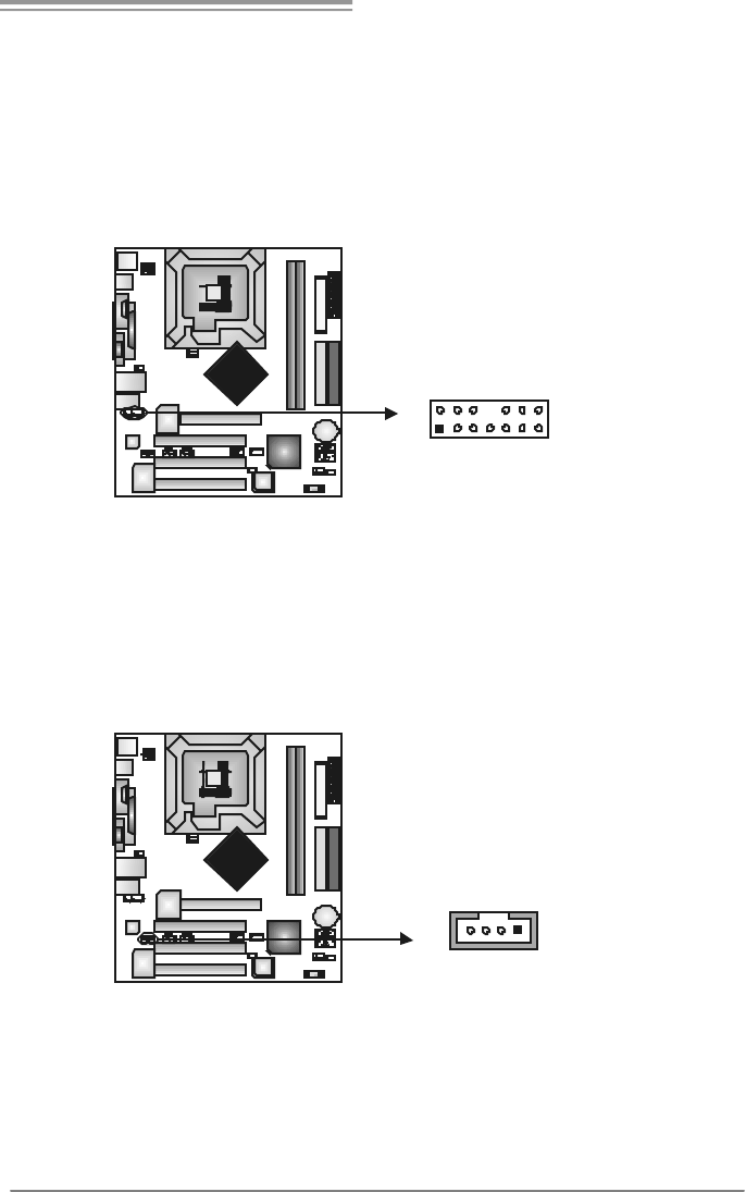
JAUDIO2: Front Panel Audio Header
This header allows user to connect the front audio output cable with the PC f ront
panel. It will disable the output on back panel audio connectors.
Pin Assignment
1 Mic in/center
2 Ground
3 Mic power/Bass
4 Audio power
5 Right line out/
Speaker out
Right
6 Right line out/
Speaker out
Right
7 Reserved
8 Key
9 Left line out/
Speaker out Left
10 Left line out/
Speaker out Left
11 Right line in/
Rear speaker
Right
12 Right line in/
Rear speaker
Right
13 Left line in/
Rear speaker Left
1
2
13
14
14 Left line in/
Rear speaker Left
JCDIN1: CD-ROM Audio-in Connector
This connector allows user to connect the audio source f rom the v ariaty dev ices,
like CD-ROM, DVD-ROM, PCI sound card, PCI TV turner card etc..
Pin
Assignment
1 Left Channel
Input
2 Ground
3 Ground
14
4 Right Channel
Input
Motherboard Manual
18
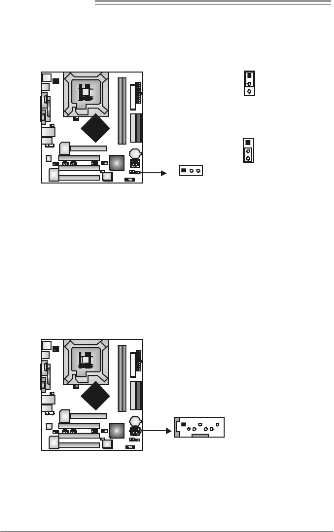
JCMOS1: Clear CMOS Header
By placing the jumper on pin2-3, it allows user to restore the BIOS saf e setting
and the CMOS data, please carefully f ollow the procedures to avoid damaging
the motherboard.
1
3
Pin 1-2 Close:
Normal Operation (default).
13
1
3
Pin 2-3 Close:
Clear CMOS data.
※ Clear CMOS Procedures:
1. Remov e AC power line.
2. Set the jumper to “Pin 2-3 close”.
3. Wait for five seconds.
4. Set the jumper to “Pin 1-2 close”.
5. Power on the AC.
6. Reset y our desired password or clear the CMOS data.
JSATA1~JSATA2: Serial ATA Connectors
The motherboard has a PCI to SATA Controller with 2 channels SATA interf ace,
it satisfies the SATA 1.0 spec and with transfer rate of 1.5Gb/s.
Pin
Assignment
1 Ground
2 TX+
3 TX-
4 Ground
5 RX-
6 RX+
SATA2
SATA1
147
7 Ground
865G Micro 775 & 865GV Micro 775
19
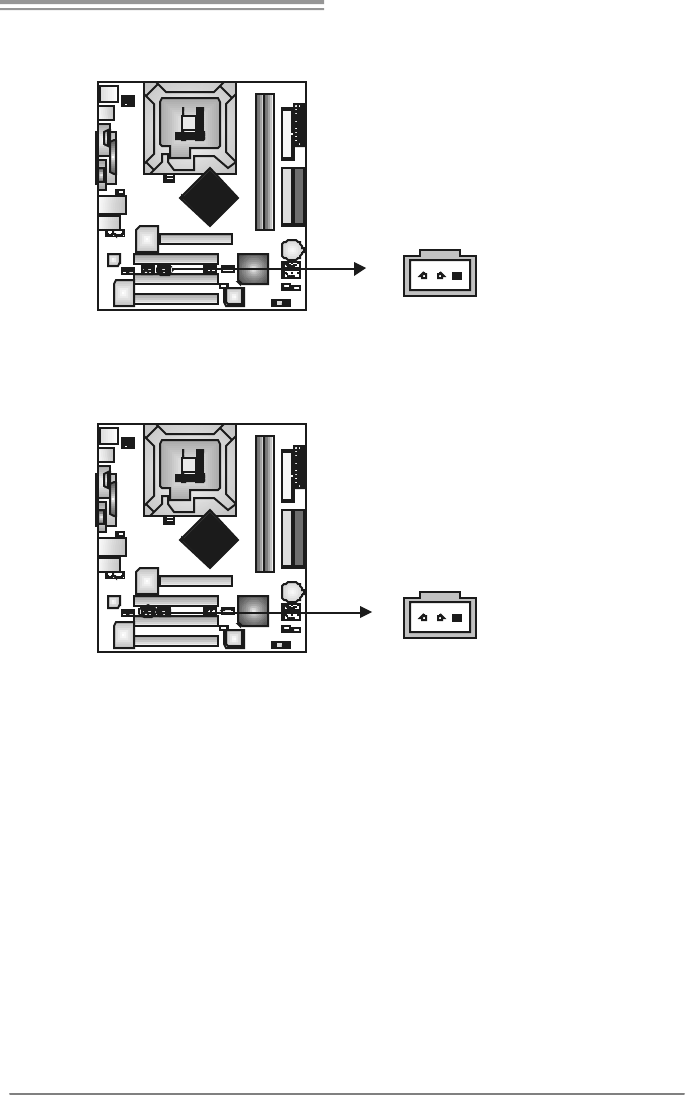
JSPDIF_OUT1: Digital Audio-out Connector
This connector allows user to connect the PCI bracket SPDIF output header.
Pin
Assignment
1 +5V
2 SPDIF_OUT
13
3 Ground
JSPDIF_IN1 (optional): Digital Audio-in Connector
This connector allows user to connect the PCI bracket SPDIF input header.
Pin
Assignment
1 +5V
2 SPDIF_IN
13
3 Ground
Motherboard Manual
20
CHAPTER 4: USEFUL HELP
4.1 DRIVER INSTALLATION NOTE
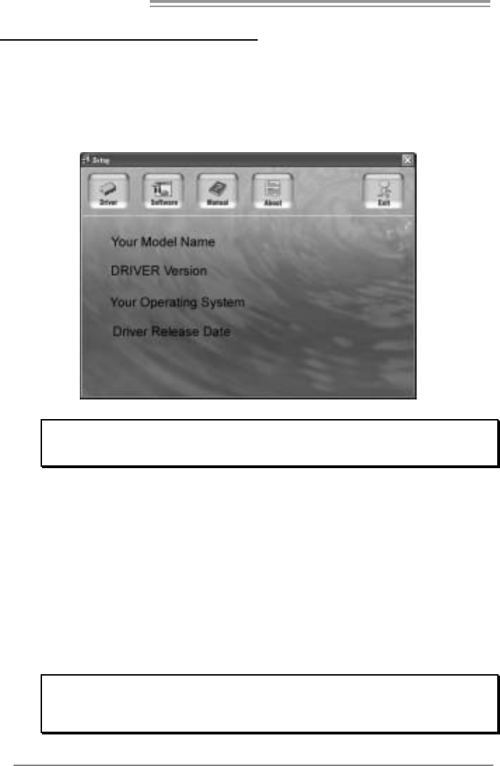
After you installed your operating system, please insert the Fully Setup
Driver CD into your optical drive and install the driver for better system
performance.
You will see the following window after you insert the CD
The setup guide will auto detect your motherboard and operating system.
Note:
If this window didn’t sho w up aft er you ins ert the Driver CD, please use file bro ws er to
locate and execute the file SETUP.EXE under your optical drive .
A. Driver Installation
To install the driver, please click on the Driver icon. The setup guide will
list the compatible driver for your motherboard and operating system.
Click on each device driver to launch the installation program.
B. Software Installation
To install the software, please click on the Software icon. The setup guide
will list the software available for your system, click on each software title
to launch the installation program.
C. Manual
Aside from the paperback manual, we also provide manual in the Driver
CD. Click on the Manual icon to browse for available manual.
Note:
You will need Acrobat R eader to open the manual file. Please download the latest version
of Acrobat Reader software from
http://www.adobe.com/products/acrobat/readstep2.html
865G Micro 775 & 865GV Micro 775
21
4.2 AWARD BIOS BEEP CODE
Beep Sound Meaning
One long beep followed by two short
beeps Video card not found or v ideo card
memory bad
High-low siren sound CPU overheated
System will shut down automatically
One Short beep when system boot-up No error found during POST
Long beeps every other second No DRAM detected or install
4.3 EXT RA INFORMATION
A. BIOS Update
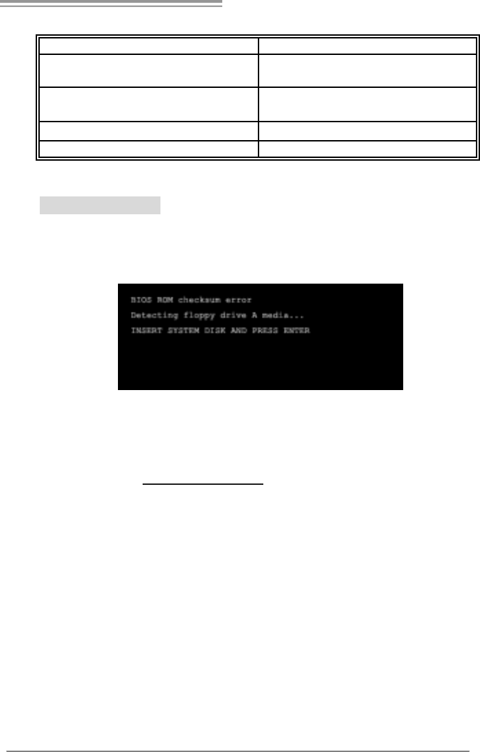
After you fail to update BIOS or BIOS is invaded by virus, the
Boot-Block function will help to restore BIOS. If the following message
is shown after boot-up the system, it means the BIOS contents are
corrupted.
In this Case, please follow the procedure below to restore the BIOS:
1. Make a bootable floppy disk.
2. Download the Flash Utility “AWDFLASH.exe” from the Biostar
website: www.biostar.com.tw
3. Confirm motherboard model and download the respectively BIOS
from Biostar website.
4. Copy “AWDFLASH.exe” and respectively BIOS into floppy disk.
5. Insert the bootable disk into floppy drive and press Enter.
6. System will boot-up to DOS prompt.
7. Type “Awdflash xxxx.bf/sn/py/r” in DOS prompt.
(xxxx means BIOS name.)
8. System will update BIOS automatically and restart.
9. The BIOS has been recovered and will work properly.

Motherboard Manual
22
B. CPU Overheated
If the system shutdown automatically after power on system for
seconds, that means the CPU protection function has been activated.
When the CPU is over heated, the motherboard will shutdown
automatically to avoid a damage of the CPU, and the system may not
power on again.
In this case, please double check:
1. The CPU cooler surface is placed evenly with the CPU surface.
2. CPU fan is rotated normally.
3. CPU fan speed is fulfilling with the CPU speed.
After confirmed, please follow steps below to relief the CPU
0protection function.
1. Remove the power cord from power supply for seconds.
2. Wai t fo r se co nd s.
3. Plug in the power cord and boot up the system.
Or you can:
1. Clear the CMOS data.
(See “Close CMOS Header: JCMOS1” section)
2. Wai t fo r se co nd s.
3. Power on the system again.

865G Micro 775 & 865GV Micro 775
23
4.4 TROUBLESHOOTING
Probable Solution
1. No power to the system at all
Power light don’t illuminate, f an
inside power supply does not turn
on.
2. Indicator light on key board does
not turn on.
1. Make sure power cable is
securely plugged in.
2. Replace cable.
3. Contact technical support.
System inoperativ e. Keyboard lights
are on, power indicator lights are lit,
and hard driv e is spinning.
Using even pressure on both ends of
the DIMM, press down firmly until the
module snaps into place.
System does not boot from hard disk
driv e, can be booted f rom optical driv e. 1. Check cable running from disk to
disk controller board. Make sure
both ends are securely plugged
in; c hec k t he driv e ty pe in t he
standard CMOS setup.
2. Backing up the hard drive is
extremely important. All hard
disks are capable of breaking
down at any time.
System only boots f rom optical driv e.
Hard disk can be read and applications
can be used but booting from hard disk
is impossible.
1. Back up data and applications
files.
2. Ref ormat the hard driv e.
Re-install applications and data
using backup disks.
Screen message says “Invalid
Conf iguration” or “CMOS Failure.” Rev iew system’s equipment. Make sur
e
correct inf ormation is in setup.
Cannot boot system after installing
second hard driv e. 1. Set master/slave jumpers
correctly.
2. Run SETUP program and select
correct driv e types. Call the drive
manuf acturers f or compatibility
with other drives.

Motherboard Manual
24
CHAPTER 5: WARPSPEEDER™
5.1 INTRODUCTION
[WarpSpeeder™], a new powerful control utility, features three
user-friendly functions including Overclock Manager, Overvoltage
Manager, and Hardware Monitor.
With the Overclock Manager, users can easily adjust the frequency they
prefer or they can get the best CPU performance with just one click. The
Overvoltage Manager, on the other hand, helps to power up CPU core
voltage and Memory voltage. The cool Hardware Monitor smartly indicates
the temperatures, voltage and CPU fan speed as well as the chipset
information. Also, in the About panel, you can get detail descriptions about
BIOS model and chipsets. In addition, the frequency status of CPU,
memory, AGP and PCI along with the CPU speed are synchronically
shown on our main panel.
Moreover, to protect users' computer systems if the setting is not
appropriate when testing and results in system fail or hang,
[WarpSpeeder™] technology assures the system stability by automatically
rebooting the computer and then restart to a speed that is either the
original system speed or a suitable one.
5.2 SYSTEM REQUIREMENT
OS Support: Windows 98 SE, Windows Me, Windows 2000, Windows XP
DirectX: DirectX 8.1 or above. (The Windows XP operating system
includes DirectX 8.1. If you use Windows XP, you do not need to install
DirectX 8.1.)
865G Micro 775 & 865GV Micro 775
25
5.3 INSTALLATION
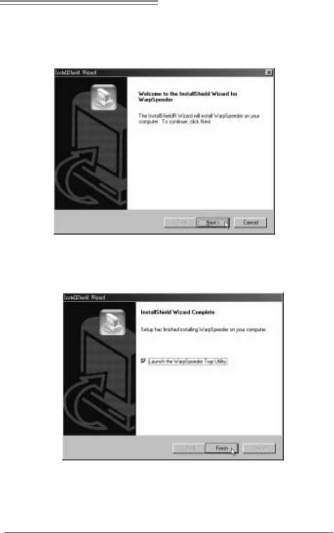
1. Execute the setup execution file, and then the following dialog will pop
up. Please click “Next” button and follow the default procedure to
install.
2. When you see the following dialog in setup procedure, it means setup
is completed. If the “Launch the WarpSpeeder Tray Utility” checkbox
is checked, the Tray Icon utility and [WarpSpeeder™] utility will be
automatically and immediately launched after you click “Finish”
button.
Usage:
The following figures are just only for reference, the screen printed in
this user manual will change according to your motherboard on hand.
Motherboard Manual
26
5.4 WARPSPEEDER™
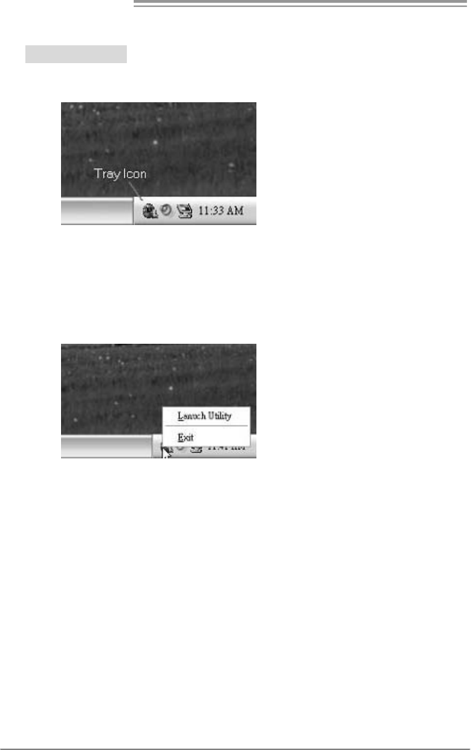
1. Tray Icon:
Whenever the Tray Icon utility is launched, it will display a little tray
icon on the right side of Windows Taskbar.
This utility is responsible for conveniently invoking [WarpSpeeder™]
Utility. You can use the mouse by clicking the left button in order to
invoke [WarpSpeeder™] directly from the little tray icon or you can
right-click the little tray icon to pop up a popup menu as following
figure. The “Launch Utility” item in the popup menu has the same
function as mouse left-click on tray icon and “Exit” item will close
Tray Icon utility if selected.
865G Micro 775 & 865GV Micro 775
27
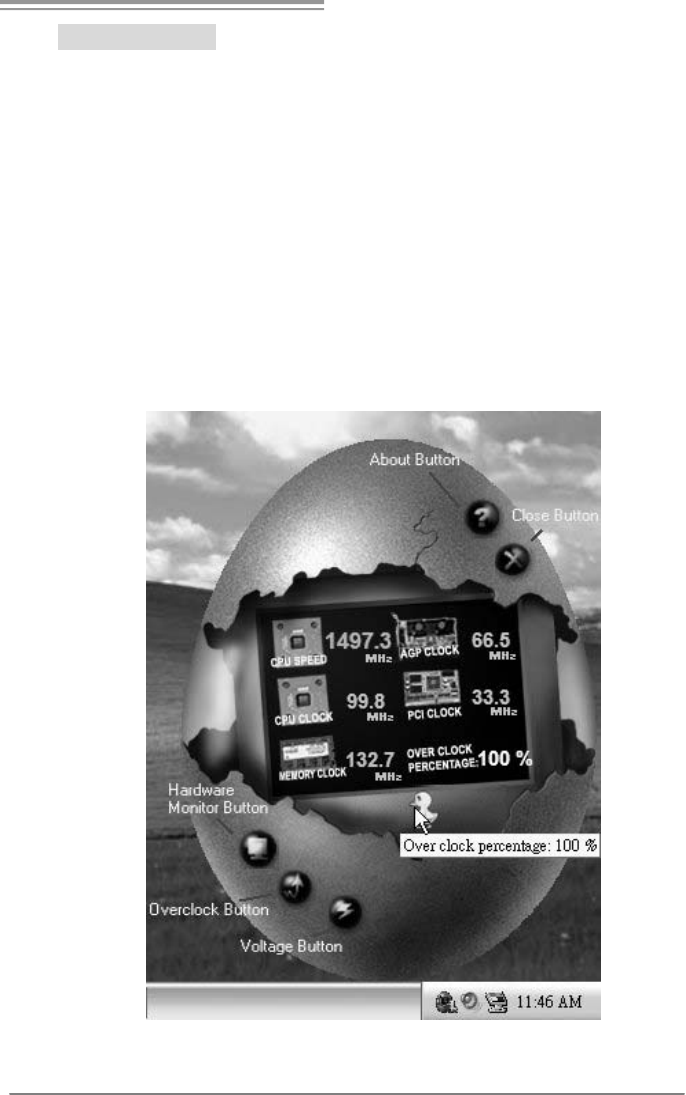
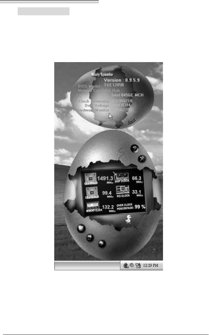
2. Main Panel
If you click the tray icon, [WarpSpeeder™] utility will be invoked.
Please refer to the following figure; the utility’s first window you will
see is Main Panel.
Main Panel contains features as follows:
a. Di spl a y the CPU Sp ee d , CPU external cl ock, M em o ry clock, AGP cl o ck,
and PCI clock information.
b. Contains About, Voltage, Overclock, and Hardware Monitor Buttons for
invoking respective panels.
c. With a user-friendly Status Animation, it can represent 3 overclock
percentage stages:
Man walking→overclock percentage from 100% ~ 110 %
Panther running→overclock percentage from 110% ~ 120%
Car racing→overclock percentage from 120% ~ above
Motherboard Manual
28
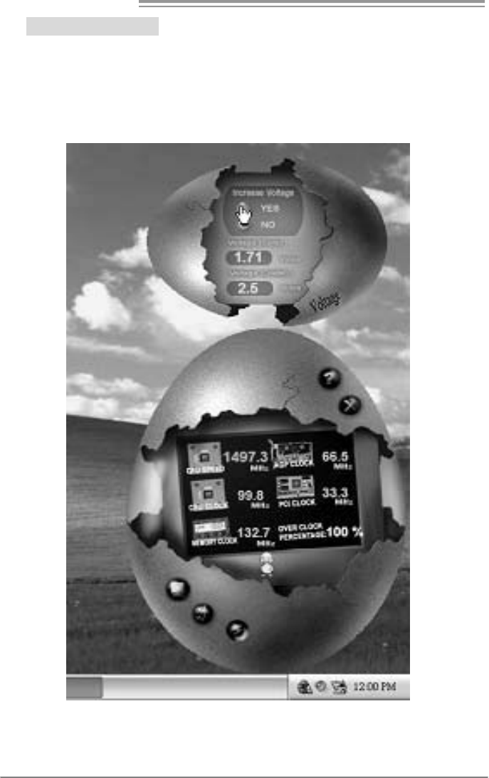
3. Voltage Panel
Click the Voltage button in Main Panel, the button will be highlighted
and the Voltage Panel will slide out to up as the following figure.
In this panel, you can decide to increase CPU core voltage and
Memory voltage or not. The default setting is “No”. If you want to get
the best performance of overclocking, we recommend you click the
option “Yes”.
865G Micro 775 & 865GV Micro 775
29
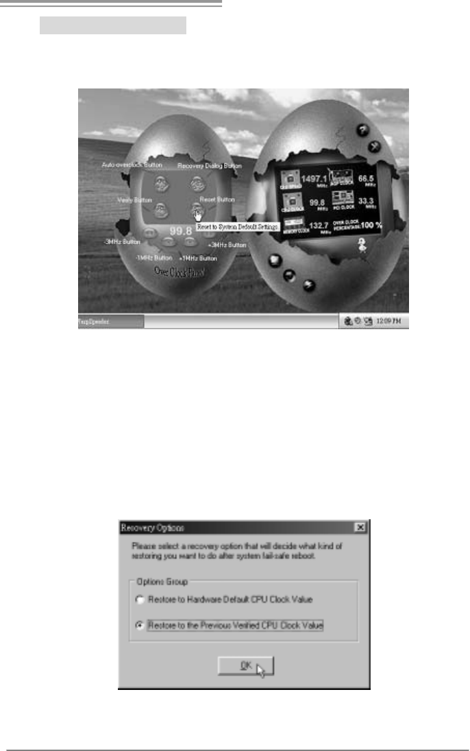
4. Overclock Panel
Click the Overclock button in Main Panel, the button will be
highlighted and the Overclock Panel will slide out to left as the
following figure.
Overclock Panel contains the these features:
a. “–3MHz button”, “-1MHz button”, “+1MHz button”, and “+3MHz button”:
provide user the ability to do real-time overclock adjustment.
Warning:
Manually overclock is potentially dangerous, especially when the
ov erclocking percentage is over 110 %. We strongly recommend you
v erify ev ery speed you overclock by click the Verify button. Or, you can
just click Auto ov erclock button and let [WarpSpeeder™] automatically
gets the best result f or y ou.
b. “Recovery Dialog button”: Pop up the following dialog. Let user select
a restoring way if system need to do a fail-safe reboot.
Motherboard Manual
30
c. “Auto-overclock button”: User can click this button and
[WarpSpeeder™] will set the best and stable performance and
frequency automatically. [WarpSpeeder™] utility will execute a
series of testing until system fail. Then system will do fail-safe
reboot by using Watchdog function. After reboot, the
[WarpSpeeder™] utility will restore to the hardware default
setting or load the verified best and stable frequency according
to the Recovery Dialog’s setting.
d. “Verify button”: User can click this button and [WarpSpeeder™]
will proceed a testing for current frequency. If the testing is ok,
then the current frequency will be saved into system registry. If
the testing fail, system will do a fail-safe rebooting. After reboot,
the [WarpSpeeder™] utility will restore to the hardware default
setting or load the verified best and stable frequency according
to the Recovery Dialog’s setting.
Note:
Because the testing programs, invoked in Auto-overclock and Verify,
include DirectDraw, Direct3D and DirectShow tests, the DirectX 8.1 or
newer runtime library is required. And please make sure y our display
card’s color depth is High color (16 bit) or True color( 24/32 bit ) that is
required f or Direct3D rendering.
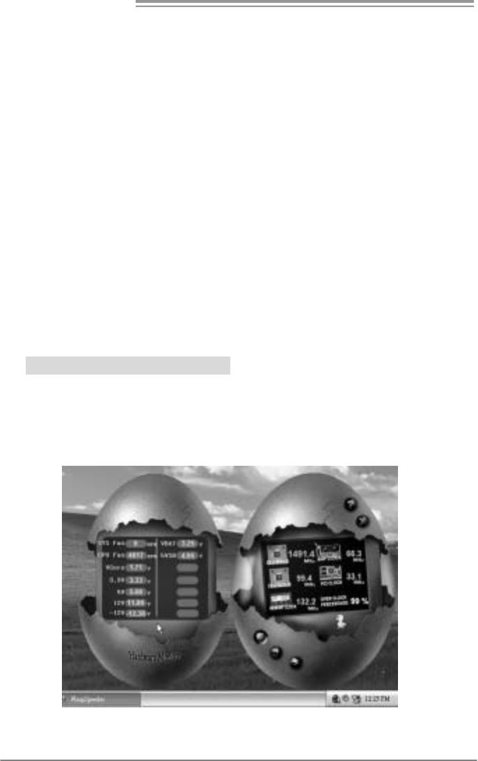
5. Hardware Monitor Panel
Click the Hardware Monitor button in Main Panel, the button will be
highlighted and the Hardware Monitor panel will slide out to left as
the following figure.
In this panel, you can get the real-time status information of your
system. The information will be refreshed every 1 second.
865G Micro 775 & 865GV Micro 775
31
6. About Panel
Click the “about” button in Main Panel, the button will be highlighted
and the About Panel will slide out to up as the following figure.
In this panel, you can get model name and detail information in hints
of all the chipset that are related to overclocking. You can also get
the mainboard’s BIOS model and the Version number of
[WarpSpeeder™] utility.
Note:
Because the overclock, overvoltage, and hardware monitor features
are controlled by several separate chipset, [WarpSpeeder™] divide
these features to separate panels. If one chipset is not on board, the
correlative button in Mai n panel will be di sabled, but will not interfere
other panels’ functions. This property can make [WarpSpeeder™]
utility more robust.

Motherboard Manual
32
APPENDENCIES: SPEC IN OTHER LANGUAGE
GERMAN
865G Micro 775 865GV Micro 775
CPU
LGA 775
Intel Pentium 4 / Pentium D / Celeron D
Prozessoren mit bis zu 3,4 GHz
Intel Core2Duo Prozessoren (nur für Ver 8.x)
Unterstützt Hyper-Threading
Execute Disable Bit
Enhanced Intel SpeedStep®
Extended Memory 64 Technology
LGA 775
Intel Pentium 4 / Pentium D / Celeron D
Prozessoren mit bis zu 3,4 GHz
Unterstützt Hyper-Threading
Execute Disable Bit
Enhanced Intel SpeedStep®
Extended Memory 64 Technology
FSB 400/ 533 / 800 MHz 400/ 533 / 800 MHz
Chipsatz Intel 865 G
Intel ICH5
Intel 865 GV
Intel ICH5
Grafik
Intel Extreme Graphics 2
Max. 64MB gemeinsam benutzter
Videospeicher
Intel Extreme Graphics 2
Max. 64MB gemeinsam benutzter
Videospeicher
Super E/A
ITE 8712F
Hardware-Überwachung
Lüfterdrehzahl-Controller
"Smart Guardian"-Funktion von ITE
ITE 8712F
Hardware-Überwachung
Lüfterdrehzahl-Controller
"Smart Guardian"-Funktion von ITE
Arbeitsspeich
er
DDR DIMM-Steckplätze x 2
Jeder DIMM unterstützt 128/256/512MB & 1GB
DDR
M ax. 2GB A rbeit ss peic her
Dual-Kanal DDR Speichermodul
Unterstützt DDR 266 / 333 / 400
DDR DIMM-Steckplätze x 2
Jeder DIMM unterstützt 128/256/512MB & 1GB
DDR
M ax. 2GB A rbeit ss peic her
Dual-Kanal DDR Speichermodul
Unterstützt DDR 266 / 333 / 400
IDE
Integrierter IDE-Controller
Ultra DMA 33 / 66 / 100 Bus Master-Modus
Unterstützt PIO-Modus 0~4
Integrierter IDE-Controller
Ultra DMA 33 / 66 / 100 Bus Master-Modus
Unterstützt PIO-Modus 0~4
SA TA
I nt e gr i ert e r S e ri al ATA - Contr o ll e r
Datentransferrate bis zu 1.5Gb/s
Konform mit der SATA-Spezifikation Version 1.0
I nt e gr i ert e r S e ri al ATA - Contr o ll e r
Datentransferrate bis zu 1.5Gb/s
Konform mit der SATA-Spezifikation Version 1.0
LAN
Realtek 8100C
10 / 100 Mb/s Auto-Negotiation
Halb-/ Vollduplex-Funktion
Realtek 8100C
10 / 100 Mb/s Auto-Negotiation
Halb-/ Vollduplex-Funktion

865G Micro 775 & 865GV Micro 775
33
865G Micro 775 865GV Micro 775
Audio-Codec
ALC 655 / ALC 658
5.1-Kanal-Audioausgabe
AC’97 Vers ion 2.3
ALC 655 / ALC 658
5.1-Kanal-Audioausgabe
AC’97 Vers ion 2.3
AGP 8X-Grafikkartensteckplatz x1 XGP Grafikkartensteckplatz x1
Steckplätze PCI-Steckplatz x3 PCI-Steckplatz x3
Diskettenlaufw erkanschluss x1 Diskettenlaufw erkanschluss x1
IDE-Ansc hluss x2 IDE-Ansc hluss x2
SATA-Anschluss x2 SATA-Anschluss x2
Fronttafelanschluss x1 Fronttafelanschluss x1
Front -Audioansc hluss x1 Front -Audioansc hluss x1
CD-IN-Ansc hluss x1 CD-IN-Ansc hluss x1
S/PDIF-Ausgangsanschluss(optional) x1 S/PDIF-Ausgangsanschluss(optional) x1
S/PDIF Eingangs ansc hluss x1 S/PDIF Eingangs ansc hluss x1
CPU-Lüfter-Sockel x1 CPU-Lüfter-Sockel x1
System-Lüfter-Sockel x1 System-Lüfter-Sockel x1
"CMOS löschen"-Soc kel x1 "CMOS löschen"-Sockel x1
US B-Ansc hluss x2 US B-Ansc hluss x2
Stromanschluss (20-polig) x1 Stromanschluss (20-polig) x1
Onboard-Ans
chluss
Stromanschluss (4-polig) x1 Stromanschluss (4-polig) x1
Rückseiten-E
/A
PS/2-Tastatur x1
PS/2-Maus x1
Serieller A nsc hluss x1
Druc keransc hluss x1
VGA-Anschluss x1
LA N-A nsc hluss x1
US B-Ansc hluss x4
Audioansc hluss x3
PS/2-Tastatur x1
PS/2-Maus x1
Serieller A nsc hluss x1
Druc keransc hluss x1
VGA-Anschluss x1
LA N-A nsc hluss x1
US B-Ansc hluss x4
Audioansc hluss x3
Platinengröße
. 215 mm (B) X 235 mm (L) 215 mm (B) X 235 mm (L)
OS-Unterstüt
zung
Windows 2000 / XP
Biostar behält sich das Recht vor, ohne
Ankündigung die Unterstützung für ein
Betriebssystem hinzuzufügen oder zu
entfernen.
Windows 2000 / XP
Biostar behält sich das Recht vor, ohne
Ankündigung die Unterstützung für ein
Betriebssystem hinzuzufügen oder zu
entfernen.

Motherboard Manual
34
FRANCE
865G Micro 775 865GV Micro 775
UC
LGA 775
Processeurs Intel Pentium 4 / Pentium D /
Celeron D jusqu'à 3,4 GHz
Processeurs Intel Core2Duo (Seulement pour
Ver 8.x)
Prend en charge les technologies
Hyper-Threading
d'exécution de bit de désactivation
Intel SpeedStep® optimisée
de mémoire étendue 64
LGA 775
Processeurs Intel Pentium 4 / Pentium D /
Celeron D jusqu'à 3,4 GHz
Prend en charge les technologies
Hyper-Threading
d'exécution de bit de désactivation
Intel SpeedStep® optimisée
de mémoire étendue 64
Bus frontal 400/ 533 / 800 MHz 400/ 533 / 800 MHz
Chipset Intel 865G
Intel ICH5
Intel 865GV
Intel ICH5
Graphiques Intel Extreme Graphics 2
Mémoire vidéo partagée maximale de 64 Mo
Intel Extreme Graphics 2
Mémoire vidéo partagée maximale de 64 Mo
Super E/S
ITE 8712F
Moniteur de matériel
Contrôleur de vitesse de ventilateur
Fonction "Gardien intelligent" de l'ITE
ITE 8712F
Moniteur de matériel
Contrôleur de vitesse de ventilateur
Fonction "Gardien intelligent" de l'ITE
Mémoire
principale
Fentes DDR DIMM x 2
Chaque DIMM prend en charge des DDR de
128/256/512 Mo et 1Go
Capacité mémoire maximale de 2 Go
Module de mémoire DDR à mode à double voie
Prend en charge la DDR 266 / 333 / 400
Fentes DDR DIMM x 2
Chaque DIMM prend en charge des DDR de
128/256/512 Mo et 1Go
Capacité mémoire maximale de 2 Go
Module de mémoire DDR à mode à double voie
Prend en charge la DDR 266 / 333 / 400
IDE
Contrôleur IDE intégré
Mode principale de Bus Ultra DMA 33 / 66 / 100
Prend en charge le mode PIO 0~4,
Contrôleur IDE intégré
Mode principale de Bus Ultra DMA 33 / 66 / 100
Prend en charge le mode PIO 0~4,
SA TA
Cont rôl eur Seri al ATA
intégré :
Taux de transfert jusqu'à 1.5 Go/s.
Conforme à la spécification SATA Version 1.0
Cont rôl eur Seri al ATA
intégré :
Taux de transfert jusqu'à 1.5 Go/s.
Conforme à la spécification SATA Version 1.0
LAN
Realtek 8100C
10 / 100 Mb/s négociation automatique
Half / Full duplex capability
Realtek 8100C
10 / 100 Mb/s négociation automatique
Half / Full duplex capability

865G Micro 775 & 865GV Micro 775
35
865G Micro 775 865GV Micro 775
Codec audio
ALC 655 / ALC658
Sortie audio à 5.1 voies
AC’97 Vers ion 2.3
ALC 655 / ALC658
Sortie audio à 5.1 voies
AC’97 Vers ion 2.3
Fente graphique AGP 8X x1 Fente graphique XGP x1
Fentes Fente PCI x3 Fente PCI x3
Connec teur de disquette x1 Connec teur de disquette x1
Connec teur IDE x2 Connecteur IDE x2
Connec t eur SATA x2 Connec t eur SATA x2
Connec teur du panneau avant x1 Connecteur du panneau avant x1
Connec teur Audio du panneau avant x1 Connecteur Audio du panneau avant x1
Connecteur d'entrée CD x1 Connecteur d'entrée CD x1
Connecteur d'entrée S/PDIF (en option) x1 Connecteur d'entrée S/PDIF (en option) x1
Connecteur de sortie S/PDIF x1 Connecteur de sortie S/PDIF x1
Embase de ventilateur UC x1 Embase de ventilateur UC x1
Embase de ventilateur système x1 Embase de ventilateur système x1
Embase d'effacement CMO S x1 Embase d'effacement CMO S x1
Connec teur USB x2 Connecteur USB x2
Connec teur d'alimentation (20 broches) x1 Connecteur d'alimentation (20 broches ) x1
Connec teur
embarqué
Connecteur d'alimentation (4 broches) x1 Connecteur d'alimentation (4 broches) x1
E/S du
panneau
arrière
Clavier PS/2 x1
Souris PS/2 x1
Port série x1
Port d'imprimante x1
Port VGA x1
Port LAN x1
Port USB x4
Fiche audio x3
Clavier PS/2 x1
Souris PS/2 x1
Port série x1
Port d'imprimante x1
Port VGA x1
Port LAN x1
Port USB x4
Fiche audio x3
Dimensions
de la carte 215mm (l) X 235 mm (H) 215mm (l) X 235 mm (H)
Support SE
Windows 2000 / XP
Biostar se réserve le droit d'ajouter ou de
supprimer le support de SE avec ou sans préavis.
Windows 2000 / XP
Biostar se réserve le droit d'ajouter ou de
supprimer le support de SE avec ou sans préavis.

Motherboard Manual
36
ITALIAN
865G Micro 775 865GV Micro 775
CPU
LGA 775
Processore Intel Pe ntium 4 / Pentium D /
Celeron D fino a 3.4 GHz
Processore Intel Core2Duo (solo per Ver
8.x)
Supporto di Hyper -T hreadi ng
Execute Disable Bit
Enha nced Intel Sp eedStep®
Tecnolo gia Extended M emory 64
LGA 775
Processore Intel Pe ntium 4 / Pentium D /
Celeron D fino a 3.4 GHz
Supporto di Hyper -T hreadi ng
Execute Disable Bit
Enha nced Intel Sp eedStep®
Tecnolo gia Extended M emory 64
FSB 400 / 533 / 800 MHz 400 / 533 / 800 MHz
Chipset Intel 865G
Intel ICH5
Intel 865GV
Intel ICH5
Grafica Intel Extreme Graphics 2
La memoria video condivisa massima è di 64MB
Intel Extreme Graphics 2
La memoria video condivisa massima è di 64MB
Super I/O
ITE 8712F
Monitoraggio hardware
Controller velocità ventolina
Funzione "Smart G uardi an" di I TE
ITE 8712F
Monitoraggio hardware
Controller velocità ventolina
Funzione "Smart G uardi an" di I TE
Memoria
principale
Alloggi DIMM DDR x 2
Ciascun DIMM supporta DDR
128 /256/ 512MB e 1GB
Capacità massima della memoria 2GB
Modulo di memoria D DR a canale do ppio
Supporto di DDR 26 6 / 3 33 / 40 0
Alloggi DIMM DDR x 2
Ciascun DIMM supporta DDR
128 /256/ 512MB e 1GB
Capacità massima della memoria 2GB
Modulo di memoria D DR a canale do ppio
Supporto di DDR 26 6 / 3 33 / 40 0
IDE
Controller IDE integrato
Modalità Bus Master Ultra DMA 33 / 66 /
100
Supporto modalità PIO Mode 0-4
Controller IDE integrato
Modalità Bus Master Ultra DMA 33 / 66 /
100
Supporto modalità PIO Mode 0-4
SATA
Controller Serial ATA integrato
Velocità di trasferimento dei dati fi no a 1. 5
Gb/s.
Compatibile specifiche SATA Versione 1.0.
Controller Serial ATA integrato
Velocità di trasferimento dei dati fi no a 1. 5
Gb/s.
Compatibile specifiche SATA Versione 1.0.

865G Micro 775 & 865GV Micro 775
37
865G Micro 775 865GV Micro 775
LAN
Realtek 8100C
Negoziazione automatica 10 / 10 0 Mb /s
Capacità Half / Full Duplex
Realtek 8100C
Negoziazione automatica 10 / 10 0 Mb /s
Capacità Half / Full Duplex
Codec
audio
ALC 655 / ALC 65 8
Uscita audio 5.1 canali
AC’97 Vers ione 2.3
ALC 655 / ALC 65 8
Uscita audio 5.1 canali
AC’97 Vers ione 2.3
Alloggio grafica A GP 8X x1 Alloggio grafica X GP x1
Alloggi
Alloggio PCI x3 Alloggio PCI x3
Connettore flo ppy x1 Connettore flo ppy x1
Connettore IDE x2 Connettore IDE x2
Connettore SATA x2 Connettore SATA x2
Connettore pa nnello fro ntale x1 Connettore pa nnello fro ntale x1
Connettore audio frontale x1 Connettore audio frontale x1
Connettore CD-in x1 Connettore CD-in x1
Connettore input S/PDIF (optional) x1 Connettore input S/PDIF (optional) x1
Connettore output SPDIF x1 Connettore output SPDIF x1
Collettore ventolina CPU x1 Collettore ventolina CPU x1
Collettore ventolina sistema x1 Collettore ventolina sistema x1
Collettore cancellazione CMOS x1 Collettore cancellazione CMOS x1
Connettore USB x2 Connettore USB x2
Connettore alimentazione (20 pin) x1 Connettore alimentazione (20 pin) x1
Connettori
su scheda
Connettore alimentazione (4 pi n) x1 Connettore alimentazione (4 pi n) x1
I/O
pannello
posteriore
Ta s t i er a P S / 2 x 1
Mouse PS/2 x1
Porta seriale x1
Porta stampante x1
Porta VGA x1
Porta LAN x1
Porta USB x4
Connettore au dio x3
Ta s t i er a P S / 2 x 1
Mouse PS/2 x1
Porta seriale x1
Porta stampante x1
Porta VGA x1
Porta LAN x1
Porta USB x4
Connettore au dio x3
Dimension
i scheda 21 5 mm (largh ezza) x 23 5 mm (altezza) 215 mm (largh ezza) x 23 5 mm (altezza)
Sistemi
operativi
supportati
Windows 2000 / XP
Biostar si riserva il diritto di aggiungere o
rimuovere il supporto di qualsiasi sistema
operativo se nza pre avviso.
Windows 2000 / XP
Biostar si riserva il diritto di aggiungere o
rimuovere il supporto di qualsiasi sistema
operativo se nza pre avviso.

Motherboard Manual
38
SPANISH
865G Micro 775 865GV Micro 775
CPU
LGA 775
Procesador Intel Pentium 4 / Pentium D / Celeron
D hasta 3,4 GHz
Procesador Intel Core2Duo(solamente para Ver
8.x)
Admite Hyper-Threading
Bit de deshabilitación de ejecución
Intel SpeedStep® Mejorado
Tecnología Extended Memory 64
LGA 775
Procesador Intel Pentium 4 / Pentium D / Celeron
D hasta 3,4 GHz
Admite Hyper-Threading
Bit de deshabilitación de ejecución
Intel SpeedStep® Mejorado
Tecnología Extended Memory 64
FSB 400 / 533 / 800 MHz 400 / 533 / 800 MHz
Conjunto de
chips
Intel 865G
Intel ICH5
Intel 865GV
Intel ICH5
Gráficos Intel Extreme Graphics 2
Memoria máxima de vídeo compartida de 64MB
Intel Extreme Graphics 2
Memoria máxima de vídeo compartida de 64MB
Súper E/S
ITE 8712F
Monitor hardware
Controlador de velocidad de ventilador
Función "Guardia inteligente" de ITE
ITE 8712F
Monitor hardware
Controlador de velocidad de ventilador
Función "Guardia inteligente" de ITE
Memoria
principal
Ranuras DIMM DDR x 2
Cada DIMM admite DDR de 128/256/512MB y
1GB
Capacidad máxima de memoria de 2GB
Módulo de memoria DDR de canal Doble
Admite DDR de 266 / 333 / 400
Ranuras DIMM DDR x 2
Cada DIMM admite DDR de 128/256/512MB y
1GB
Capacidad máxima de memoria de 2GB
Módulo de memoria DDR de canal Doble
Admite DDR de 266 / 333 / 400
IDE
Controlador IDE integrado
Modo bus maestro Ultra DMA 33 / 66 / 100
Soporte los Modos PIO 0~4.
Controlador IDE integrado
Modo bus maestro Ultra DMA 33 / 66 / 100
Soporte los Modos PIO 0~4.
SA TA
Controlador ATA Serie Integrado
Tasas de transferencia de hasta 1.5 Gb/s.
Compatible con la versión SATA 1.0.
Controlador ATA Serie Integrado
Tasas de transferencia de hasta 1.5 Gb/s.
Compatible con la versión SATA 1.0.
Red Local
Realtek 8100C
Negociac ión de 10 / 100 Mb/s
Funciones Half / Full dúplex
Realtek 8100C
Negociac ión de 10 / 100 Mb/s
Funciones Half / Full dúplex

865G Micro 775 & 865GV Micro 775
39
865G Micro 775 865GV Micro 775
Códecs de
sonido
ALC 655 /ALC 658
Salida de sonido de 5. 1 canales
AC’97 Vers ión 2.3
ALC 655 /ALC 658
Salida de sonido de 5. 1 canales
AC’97 Vers ión 2.3
Ranura de gráficos AGP x8 x1 Ranura de gráficos XGP x1
Ranuras Ranura PCI X3 Ranura PCI X3
Conector disco flexible X1 Conector disco flexible X1
Conector IDE X2 Conector IDE X2
Conec t or SATA X 2 Conec t or SATA X 2
Conector de panel frontal X1 Conector de panel frontal X1
Conector de sonido frontal X1 Conector de sonido frontal X1
Conector de entrada de CD X1 Conector de entrada de CD X1
Conector de entrada S/PDIF x1
(opcional)
Conector de entrada S/PDIF x1
(opcional)
Conector de salida S/PDIF X1 Conector de salida S/PDIF X1
Cabecera de ventilador de CPU X1 Cabecera de ventilador de CPU X1
Cabecera de ventilador de sistema X1 Cabecera de ventilador de sistema X1
Cabecera de borrado de CMOS X1 Cabecera de borrado de CMOS X1
Conector USB X2 Conector USB X2
Conector de alimentación X1
(20 patillas)
Conector de alimentación X1
(20 patillas)
Conectores
en placa
Conector de alimentación X1
(4 patillas)
Conector de alimentación X1
(4 patillas)
Panel
trasero de
E/S
Te c l ado P S/ 2 X 1
Ratón PS/2 X1
Puerto serie X1
Puerto de impresora X1
Puerto VGA X1
Puerto de red local X1
Puerto USB X4
Conector de sonido X3
Te c l ado P S/ 2 X 1
Ratón PS/2 X1
Puerto serie X1
Puerto de impresora X1
Puerto VGA X1
Puerto de red local X1
Puerto USB X4
Conector de sonido X3
Ta m a ño d e
la placa 215 mm. (A) X 235 mm. (H) 215 mm. (A) X 235 mm. (H)
Soporte de
sistema
operativo
Windows 2000 / XP
Biostar se reserva el derecho de añadir o retirar
el soporte de cualquier SO con o sin aviso previo.
Windows 2000 / XP
Biostar se reserva el derecho de añadir o retirar
el soporte de cualquier SO con o sin aviso previo.

Motherboard Manual
40
PORTUGUESE
865G Micro 775 865GV Micro 775
CPU
LGA 775
Processador Intel Pentium 4 / Pentium D /
Celeron D até 3,4 GHz
Processador Intel Core2Duo (apenas para os
modelos Ver 8.x)
Suporta as tecnologias Hyper-Threading
Execute Disable Bit
Enhanced Intel SpeedStep®
Extended Memory 64
LGA 775
Processador Intel Pentium 4 / Pentium D /
Celeron D até 3,4 GHz
Suporta as tecnologias Hyper-Threading
Execute Disable Bit
Enhanced Intel SpeedStep®
Extended Memory 64
FSB 400/ 533 / 800 MHz 400/ 533 / 800 MHz
Chipset Intel 865G
Intel ICH5
Intel 865GV
Intel ICH5
Placa
gráfica
Intel Extreme Graphics 2
Memória de vídeo máxima partilhada: 64 MB
Intel Extreme Graphics 2
Memória de vídeo máxima partilhada: 64 MB
Es pec ifi caçã
o Super I/O
ITE 8712F
Monitorização do hardware
Controlador da velocidade da ventoinha
Função "Smart Guardian" da ITE
ITE 8712F
Monitorização do hardware
Controlador da velocidade da ventoinha
Função "Smart Guardian" da ITE
Memória
principal
Ranhuras DIMM DDR x2
Cada módulo DIMM su
p
orta uma memória DDR
de 128/256/512 MB & 1 GB
Capacidade máxima de memória: 2 GB
Módulo de memória DDR de canal duplo
Suporta módulos DDR 266 / 333 / 400
Ranhuras DIMM DDR x2
Cada módulo DIMM suporta uma memória DDR
de 128/256/512 MB & 1 GB
Capacidade máxima de memória: 2 GB
Módulo de memória DDR de canal duplo
Suporta módulos DDR 266 / 333 / 400
IDE
Controlador IDE integrado
Modo Bus master Ultra DMA 33 / 66 / 100
Suporta o modo PIO 0~4.
Controlador IDE integrado
Modo Bus master Ultra DMA 33 / 66 / 100
Suporta o modo PIO 0~4.
SA TA
Controlador Serial ATA integrado
Velocidades de transmissão de dados até 1.5
Gb/s.
Compatibilidade com a especificação SATA
v e rs ã o 1. 0.
Controlador Serial ATA integrado
Velocidades de transmissão de dados até 1.5
Gb/s.
Compatibilidade com a especificação SATA
v e rs ã o 1. 0.

865G Micro 775 & 865GV Micro 775
41
865G Micro 775 865GV Micro 775
LAN
Realtek 8100C
Auto negociação de 10 / 100 Mb/s
Capacidade semi/full-duplex
Realtek 8100C
Auto negociação de 10 / 100 Mb/s
Capacidade semi/full-duplex
Codec de
som
ALC 655 / ALC 658
Saída de áudio de 5.1 canais
AC’97 Vers ão 2. 3
ALC 655 / ALC 658
Saída de áudio de 5.1 canais
AC’97 Vers ão 2. 3
Ranhura gráfica AGP 8X x1 Ranhura gráfica XGP x1
Ranhuras
Ranhura PCI x3 Ranhura PCI x3
Conector da unidade de disquetes x1 Conector da unidade de disquetes x1
Conector IDE x2 Conector IDE x2
Conec t or SATA x2 C onec t or SATA x2
Conector do painel frontal x1 Conector do painel frontal x1
Conector de áudio frontal x1 Conector de áudio frontal x1
Conector para entrada de CDs x1 Conector para entrada de CDs x1
Conector de entrada S/PDIF (opcional) x1 Conector de entrada S/PDIF (opcional) x1
Conector de saída S/PDIF x1 Conector de saída S/PDIF x1
Conector da ventoinha da CPU x1 Conec tor da ventoinha da CPU x1
Conector da ventoinha do sistema x1 Conec tor da ventoinha do sistema x1
Conector para limpeza do CMOS x1 Conector para limpeza do CMOS x1
Conector USB x2 Conector USB x2
Conector de alimentação (20 pinos) x1 Conector de alimentação (20 pinos) x1
Conectores
na placa
Conector de alimentação (4 pinos) x1 Conector de alimentação (4 pinos) x1
Entradas/S
aídas no
painel
traseiro
Te c l ado P S/ 2 x 1
Rato PS/2 x1
Port a séri e x1
Port a para im pr ess ora x1
Porta VGA x1
Porta LAN x1
Porta USB x4
Tomada de áudio x3
Te c l ado P S/ 2 x 1
Rato PS/2 x1
Port a séri e x1
Port a para im pr ess ora x1
Porta VGA x1
Porta LAN x1
Porta USB x4
Tomada de áudio x3
Tamanho
da placa 215 mm (L) X 235 mm (A) 215 mm (L) X 235 mm (A)
Sistemas
operativos
suportados
Windows 2000 / XP
A Biostar reserva-se o direito de adicionar ou
remover suporte para qualquer sistema
operativo com ou sem aviso prévio.
Windows 2000 / XP
A Biostar reserva-se o direito de adicionar ou
remover suporte para qualquer sistema
operativo com ou sem aviso prévio.

Motherboard Manual
42
POLISH
865G Micro 775 865GV Micro 775
Procesor
LGA 775
Procesor Intel Pentium 4 / Pentium D / Celeron D
do 3,4 GHz
Procesor Intel Core2Duo (wyłącz nie dla V er 8.x)
Obsługa Hyper-Threading
Execute Disable Bit
Enhanced Intel SpeedStep®
Extended Memory 64 Technology
LGA 775
Procesor Intel Pentium 4 / Pentium D / Celeron D
do 3,4 GHz
Obsługa Hyper-Threading
Execute Disable Bit
Enhanced Intel SpeedStep®
Extended Memory 64 Technology
FSB 400/ 533 / 800 MHz 400/ 533 / 800 MHz
Chipset Intel 865G
Intel ICH5
Intel 865GV
Intel ICH5
Grafika
Intel Extreme Graphics 2
Maks. wielkość ws półdzielonej pamięci video
wynosi 64MB
Intel Extreme Graphics 2
Maks. wielkość ws półdzielonej pamięci video
wynosi 64MB
Pamięć
główna
Gniazda DDR DIMM x 2
Każde gniazdo DIMM obsługuje m oduły
128/256/512MB oraz 1GB DDR
Maks. wielkość pa mi ęci 2GB
Moduł pamięci DDR z trybem podw ójnego
kanału
Obsługa DDR 266 / 333 / 400
Gniazda DDR DIMM x 2
Każde gniazdo DIMM obsługuje m oduły
128/256/512MB oraz 1GB DDR
Maks. wielkość pa mi ęci 2GB
Moduł pamięci DDR z trybem podw ójnego
kanału
Obsługa DDR 266 / 333 / 400
Super I/O
ITE 8712F
Monitor H/W
Kontroler prędkości wentylatora
Funkcja ITE "Smart Guardian"
ITE 8712F
Monitor H/W
Kontroler prędkości wentylatora
Funkcja ITE "Smart Guardian"
IDE
Z i nt e g ro w an y k o nt r ol e r I D E
Ultra DMA 33 / 66 / 100 Tryb Bus Master
obsługa PIO tryb 0~4
Z i nt e g ro w an y k o nt r ol e r I D E
Ultra DMA 33 / 66 / 100 Tryb Bus Master
obsługa PIO tryb 0~4
SA TA
Zintegrowany kontroler Serial ATA
Transfer danych do 1.5 Gb/s.
Zgodność ze specyfikacją SATA w wersji 1.0.
Zintegrowany kontroler Serial ATA
Transfer danych do 1.5 Gb/s.
Zgodność ze specyfikacją SATA w wersji 1.0.
LAN
Realtek 8100C
10 / 100 Mb/s z automatyczną negoc jac ją
szybkości
Realtek 8100C
10 / 100 Mb/s z automatyczną negoc jac ją
szybkości

865G Micro 775 & 865GV Micro 775
43
865G Micro 775 865GV Micro 775
Działanie w trybie połow icz n e g o / p ełnego
dupleksu
Działanie w trybie połow icz n e g o / p ełnego
dupleksu
Kodek
dźwiękowy
ALC 655 / ALC 658
5.1 kanałow e wy j ście audio
AC’97 w wersji 2.3
ALC 655 / ALC 658
5.1 kanałow e wy j ście audio
AC’97 w wersji 2.3
Gniazdo grafiki AGP 8X x1 Gniazdo grafiki XGP x1
Gniazda
Gniazdo PCI x3 Gniazdo PCI x3
Złącz e napędu dyskietek x1 Złącze napędu dyskietek x1
Złącz e IDE x2 Z łącz e IDE x2
Złącz e SA TA x2 Z łącz e SA TA x2
Złącze panela przedniego x1 Złącze panela przedniego x1
Przednie złącz e audio x1 Przednie z łą cze audio x1
Złącz e w ejścia CD x1 Z łącz e w ejścia CD x1
Złącz e w ejścia S/PDIF (opc ja) x1 Złącz e w ejścia S/PDIF (opc ja) x1
Złącz e w yjści a S /PDIF x1 Z łącz e w yjścia S /PDIF x1
Złącz e głów kowe w ent yl at or a pr oc es ora x 1 Z łącz e głów kowe w e nt yl at or a pr oc es o ra x 1
Złącz e głów kowe w ent yl at or a
systemowego x1
Złącz e głów kowe w ent yl at or a
systemowego x1
Złącz e główkowe kasowania CMOS x1 Złącz e główkowe kasowania CMOS x1
Złącz e USB x2 Z łącz e USB x2
Złącze zas ilania (20 pinowe) x1 Złącze zas ilania (20 pinow e) x1
Złącz a
wbudowane
Złącze zas ilania (4 pinowe) x1 Złącze zas ilania (4 pinowe) x1
Back Panel
I/O
Klawiatura PS/2 x1
Mysz PS/2 x1
Port szeregowy x1
Port drukarki x1
Port VGA x1
Port LAN x1
Port USB x4
Gniazdo audio x3
Klawiatura PS/2 x1
Mysz PS/2 x1
Port szeregowy x1
Port drukarki x1
Port VGA x1
Port LAN x1
Port USB x4
Gniazdo audio x3
Wymiary
płyty 215 mm (S) X 235 mm (W) 215 mm (S) X 235 mm (W)
Obsluga
systemu
operacyjne
go
Windows 2000 / XP
Biostar z astrzega s obie prawo dodawania lub
odwoływania obsługi dowolnego systemu
o p e r ac y jn e go b e z po wi a dom i e ni a.
Windows 2000 / XP
Biostar z astrzega s obie prawo dodawania lub
odwoływania obsługi dowolnego systemu
o p e r ac y jn e go b e z po wi a dom i e ni a.

Motherboard Manual
44
RUSSIAN
865G Micro 775 865GV Micro 775
CPU
(центральн
ый
проц ессор)
LGA 775
Процессор Intel Pentium 4 / Pentium D / Celeron
D до 3.4 ГГц
Процессор Intel Core2Duo (только для Ver
8.x)
Поддержка технологий Hyper-Threading
Execute Disable Bit
Enhanced Intel SpeedStep®
Extended Memory 64 Technology
LGA 775
Процессор Intel Pentium 4 / Pentium D / Celeron
D до 3.4 ГГц
Поддержка технологий Hyper-Threading
Execute Disable Bit
Enhanced Intel SpeedStep®
Extended Memory 64 Technology
FSB 400/ 533 / 800 МГц 400/ 533 / 800 МГц
Набор
микросхем
Intel 865G
Intel ICH5
Intel 865GV
Intel ICH5
Графика
Intel Extreme Graphics 2
Максимальная совместно используемая видео
память составляет 64 МБ
Intel Extreme Graphics 2
Максимальная совместно используемая видео
память составляет 64 МБ
Основная
память
Слоты DDR DIMM x 2
Каждый модуль DIMM поддерживает
128/256/512МБ & 1ГБ DDR
Максимальная ём к ос ть памяти 2 ГБ
Модуль памяти с двухканальным режимом
DDR
Поддержка DDR 266 / 333 / 400
Слоты DDR DIMM x 2
Каждый модуль DIMM поддерживает
128/256/512МБ & 1ГБ DDR
Максимальная ём к ос ть памяти 2 ГБ
Модуль памяти с двухканальным режимом
DDR
Поддержка DDR 266 / 333 / 400
Super I/O
ITE 8712F
А ппаратны й монитор
Регулятор скорости
Функция ITE "Smart Guardian"
(Интеллектуальная защита)
ITE 8712F
А ппаратны й монитор
Регулятор скорости
Функция ITE "Smart Guardian"
(Интеллектуальная защита)
IDE
Встроенное ус т ро й с тв о управления
встроенными интерфейсами устройств
Режим "хозяина" шины Ultra DMA 33 / 66 / 100
Поддержка реж има PIO 0~4,
Встроенное ус тр ой с тво управления
встроенными интерфейсами устройств
Режим "хозяина" шины Ultra DMA 33 / 66 / 100
Поддержка реж има PIO 0~4,
SA TA
Встроенное последовательное устройство
управления ATA
скорость передачи данных до 1.5 гигабит/с.
Соответствие с пец ификац ии SA TA версия 1. 0.
Встроенное последовательное устройство
управления ATA
скорость передачи данных до 1.5 гигабит/с.
Соответствие с пец ификац ии SA TA версия 1. 0.
Локальная
сеть
Realtek 8100C
Автоматичес кое согласование 10 / 100 Мб/с
Частичная / полная дуплексная способность
Realtek 8100C
Автоматичес кое согласование 10 / 100 Мб/с
Частичная / полная дуплексная способность

865G Micro 775 & 865GV Micro 775
45
865G Micro 775 865GV Micro 775
Звуковой
кодек
ALC 655 / ALC 658
Шестиканальный звуковой вы х о д
AC’97 Версия 2. 3
ALC 655 / ALC 658
Шестиканальный звуковой вы х о д
AC’97 Версия 2. 3
Графический слот AGP 8X x1 Графический слот XGP x1
Слоты Слот PCI x3 Слот PCI x3
Разъём НГМД x1 Разъём НГМД x1
Разъём IDE x2 Разъём IDE x2
Разъём SATA x2 Разъём SATA x2
Разъём на лицевой панели x1 Разъём на лицевой панели x1
Входной звуковой разъём x1 Входной звуковой разъём x1
Разъём ввода для CD x1 Разъём ввода для CD x1
Разъём ввода для S/PDIF
(дополнительно) x1
Разъём ввода для S/PDIF
(дополнительно) x1
Разъём вы в о д а для S/PDIF x1 Разъём вы в о д а для S/PDIF x1
Контактирующее приспос обление
вентилятора центрального проц ес сора x1
Контактирующее приспос обление
вентилятора центрального проц ес сора x1
Контактирующее приспос обление
вентилятора системы x1
Контактирующее приспос обление
вентилятора системы x1
Открытое ко нт а к т ир ую щ е е приспособление
CMOS x1
Открытое ко нт а к т ир ую щ е е приспособление
CMOS x1
USB-разъём x2 USB-разъём x2
Разъем питания (20 вы в о д ) x 1 Разъем питания (20 вы в о д ) x 1
Встроенны
й раз ъём
Разъем питания (4 вы в о д) x 1 Разъем питания (4 вы в о д) x 1
Задняя
панель
средств
ввода-вы в
ода
Клавиатура PS/2 x1
Мышь PS / 2 x 1
Последовательный порт x1
Порт подключения принтера x1
Порт VGA x1
Порт LAN x1
USB-порт x4
Гнездо для подключения
наушников x3
Клавиатура PS/2 x1
Мышь PS / 2 x 1
Последовательный порт x1
Порт подключения принтера x1
Порт VGA x1
Порт LAN x1
USB-порт x4
Гнездо для подключения
наушников x3
Размер
панели 215 мм (Ш) X 235 мм (В) 215 мм (Ш) X 235 мм (В)
Поддержка
OS
Windows 2000 / XP
Biostar сохраняет за собой право добавлять
или удалять средства обеспечения для OS с
или без предварительного уведомления.
Windows 2000 / XP
Biostar сохраняет за собой право добавлять
или удалять средства обеспечения для OS с
или без предварительного уведомления.

Motherboard Manual
46
ARABIC
865G Micro 775 865GV Micro 775
ﺔ ﺠﻟﺎ ﻌ ﻤ ﻟا ةﺪﺣو
ﺔﻳﺰآﺮﻤ ﻟا
LGA 775
تﺎ ﺠﻟﺎ ﻌﻡ Intel Pentium 4 / Pentium D / Celeron D
ﺑددﺮﺘ ﻳ ﻰﻟإ ﻞﺼ3. 4 ﺰﺕ ﺮه ﺎﺠ ﻴﺝ
Intel Core2Duo ( ﻲﻓ8.xﻂﻘ ﻓ )
تﺎ ﻴﻨﻘﺕ ﻢﻋ ﺪ ﺕ Hyper-Threadin
g
Execute Disable Bit
Enhanc ed Intel S
p
eedSte
p
®
Extended Memory 64 Technology
LGA 775
تﺎ ﺠﻟﺎ ﻌﻡ Intel Pentium 4 / Pentium D / Celeron D
ﺑددﺮﺘ ﻳ ﻰﻟإ ﻞﺼ3. 4 ﺰﺕ ﺮه ﺎﺠ ﻴﺝ
تﺎ ﻴﻨﻘﺕ ﻢﻋ ﺪ ﺕ Hyper-Threadin
g
Execute Disable Bit
Enhanc ed Intel S
p
eedSte
p
®
Extended Memory 64 Technology
ﻞﻗﺎﻨﻟا ﻲﻡﺎﻡﻷا ﻲﺒﻥ ﺎﺠﻟا ددﺮﺕ 400/ 533 / 800 ﺰﺕﺮه ﺎﺠﻴﻡ
ددﺮﺕ 400/ 533 / 800 ﺰﺕﺮه ﺎﺠﻴﻡ
ﺢﺋ اﺮﺸ ﻟا ﺔﻋﻮﻤﺠﻡ
Intel 865G
Intel ICH5
Intel 865GV
Intel ICH5
تﺎﻡﻮ ﺳﺮ ﻟا ﺔﻗﺎ ﻄﺑ
Intel Extreme Graphics 2
ا ةﺮآاﺬﻟ ﺔﻌﺳ ﻰﺼ ﻗ أ ﺔآ ﺮﺘ ﺸﻤ ﻟا ﻮﻳﺪﻴﻔﻟ 64ﺖﻳﺎ ﺑ ﺎﺠﻴﻡ
Intel Extreme Graphics 2
ﺔآ ﺮﺘ ﺸﻤ ﻟا ﻮﻳﺪﻴﻔﻟا ةﺮآاﺬﻟ ﺔﻌﺳ ﻰﺼ ﻗ أ64ﺖﻳﺎ ﺑ ﺎﺠﻴﻡ
ﺔﻴﺴ ﻴﺋﺮﻟا ةﺮآ اﺬﻟا
ﺔﺤﺘ ﻓDDR DIMMدﺪﻋ2
ﺔﺤﺘﻓ ﻞآ ﻢﻋ ﺪ ﺕ DIMM عﻮ ﻥ ﻦﻡ ةﺮآ اذ ﻢﻋ ﺪﺕ DDR ﺔﻌﺳ 128/256/512
و ﺖﻳ ﺎﺑ ﺎﺠﻴﻡ1 ﺎﺠﻴﺝﺖﻳ ﺎﺑ
ىﻮﺼﻗ ةﺮآاذ ﺔﻌﺳ2 ﺖﻳ ﺎﺑ ﺎﺠﻴﺝ
ةﺮآ اذ ةﺪﺣوDDR ﺔﻳ دﺎ ﺣأ/ةﺎ ﻨﻘﻟا ﺔﺝودﺰﻡ
عﻮ ﻥ ﻦﻡ ةﺮآ اﺬﻟا ﻢﻋ ﺪ ﺕ DDR تﺎﻌﺳ 266 / 333 / 400ﺖﻳ ﺎﺑ ﺎﺠﻴﻡ
ﺔﺤﺘ ﻓDDR DIMMدﺪﻋ2
ﺔﺤﺘﻓ ﻞآ ﻢﻋ ﺪ ﺕ DIMM عﻮ ﻥ ﻦﻡ ةﺮآ اذ ﻢﻋ ﺪﺕ DDR ﺔﻌﺳ 128/256/512
و ﺖﻳ ﺎﺑ ﺎﺠﻴﻡ1 ﺎﺠﻴﺝﺖﻳ ﺎﺑ
ىﻮﺼﻗ ةﺮآاذ ﺔﻌﺳ2 ﺖﻳ ﺎﺑ ﺎﺠﻴﺝ
ةﺮآ اذ ةﺪﺣوDDR ﺔﻳ دﺎ ﺣأ/ةﺎ ﻨﻘﻟا ﺔﺝودﺰﻡ
ﻥ ﻦﻡ ةﺮآ اﺬﻟا ﻢﻋ ﺪ ﺕ عﻮ DDR تﺎﻌﺳ 266 / 333 / 400ﺖﻳ ﺎﺑ ﺎﺠﻴﻡ
Super I/O
ITE 8712F
ةﺰﻬ ﺝﻷ ا ﺔﻟﺎﺣ ﺔﻓﺮﻌﻤﻟ ﺐﻗاﺮﻡ
ﺔﺣوﺮﻤﻟا ﺔﻋﺮﺳ ﻲﻓ ﺐﻗاﺮﻡ
ﺔﻔﻴﻇو"Smart Guardian" ﻦﻡ ITE
ITE 8712F
ةﺰﻬ ﺝﻷ ا ﺔﻟﺎﺣ ﺔﻓﺮﻌﻤﻟ ﺐﻗاﺮﻡ
ﺔﺣوﺮﻤﻟا ﺔﻋﺮﺳ ﻲﻓ ﺐﻗاﺮﻡ
ﺔﻔﻴﻇو"Smart Guardian" ﻦﻡ ITE
ﺬﻔ ﻨﻡIDE
ﻢﻜﺤﺘﻡIDEﻞﻡﺎﻜﺘﻡ
ﻗﺎﻥ ﺔ ﻴﻨﻘﺘ ﺑ ﻞUltra DMA 33
/
66
/
100
ﻲﺴ ﻴﺋر ﻊﺿ و
ﻊﺿو ﻢﻋدPIO Mode 0~4
ﻢﻜﺤﺘﻡIDEﻞﻡﺎﻜﺘﻡ
ﺔ ﻴﻨﻘﺘ ﺑ ﻞﻗﺎﻥUltra DMA 33
/
66
/
100
ﻲﺴ ﻴﺋر ﻊﺿ و
ﻊﺿو ﻢﻋدPIO Mode 0~4
SATA
ﻢﻜﺤﺘﻡSerial ATAﻞﻡﺎﻜﺘﻡ
ﻰﻟإ ﻞﺼﺕ تﺎﻋﺮﺴﺑ تﺎﻥ ﺎﻴﺒﻟا ﻞﻘﻥ1. 5 ﺖﺑ ﺎﺠ ﻴﺝ/ﺔﻴﻥﺎﺛ.
تﺎﻔﺹاﻮﻤﻟ ﺔﻘﺑﺎﻄﻡSA TA راﺪﺹﻹا 1.0.
ﻢﻜﺤﺘﻡSerial ATAﻞﻡﺎﻜﺘﻡ
ﻰﻟإ ﻞﺼﺕ تﺎﻋﺮﺴﺑ تﺎﻥ ﺎﻴﺒﻟا ﻞﻘﻥ1. 5 ﺖﺑ ﺎﺠ ﻴﺝ/ﺔﻴﻥﺎﺛ.
تﺎﻔﺹاﻮﻤﻟ ﺔﻘﺑﺎﻄﻡSA TA راﺪﺹﻹا 1.0.
ﺔ ﻴﻠﺧ اد ﺔﻜﺒﺵ
10/100
Realtek 8100C
ﻲﺋﺎﻘﻠﺕ ضوﺎ ﻔﺕ10/100 ﺖﻳ ﺎﺑ ﺎﺠﻴﻡ /ﺔﻴﻥﺎ ﺛ
ﻞﻡﺎﻜﻟا جودﺰﻤ ﻟا ﻞﻘﻨﻟا ﺔﻴﻥﺎﻜﻡإ/ﻲﻔﺼ ﻨﻟا
Realtek 8100C
ﻲﺋﺎﻘﻠﺕ ضوﺎ ﻔﺕ10/100 ﻴﻡ ﺖﻳ ﺎﺑ ﺎﺠ /ﺔﻴﻥﺎ ﺛ
ﻞﻡﺎﻜﻟا جودﺰﻤ ﻟا ﻞﻘﻨﻟا ﺔﻴﻥﺎﻜﻡإ/ﻲﻔﺼ ﻨﻟا
تﻮﺼ ﻟا ﻚﻳ دﻮ آ
ALC655 / ALC 658
5.1تﻮﺼ ﻟا جﺮﺨ ﻟ تاﻮ ﻨ ﻗ
را ﺪ ﺹ ﻹ ا 2.3 ﻦﻡ AC’97
ALC655 / ALC 658
5.1تﻮﺼ ﻟا جﺮﺨ ﻟ تاﻮ ﻨ ﻗ
را ﺪ ﺹ ﻹ ا 2.3 ﻦﻡ AC’97

865G Micro 775 & 865GV Micro 775
47
865G Micro 775 865GV Micro 775
ﺔﺤﺘ ﻓAGP ﺔﺌﻓ 8Xتﺎﻡﻮﺳﺮﻟا ﺔﻗ ﺎ ﻄﺒﻟ دﺪﻋ 1 ﺔﺤﺘ ﻓXGPﻡﻮﺳﺮﻟا ﺔﻗﺎﻄﺒﻟ ﺔﺌﻓ تﺎ دﺪﻋ 1 تﺎ ﺤﺘﻔ ﻟا
ﺔﺤﺘ ﻓPCI دﺪﻋ3 ﺔﺤﺘﻓPCI دﺪﻋ3
ﺔﻥﺮ ﻡ صاﺮﻗأ كﺮﺤﻡ ﺬﻔﻨﻡ دﺪﻋ1 ﺔﻥﺮ ﻡ صاﺮﻗأ كﺮﺤﻡ ﺬﻔﻨﻡ دﺪﻋ1
ﺬﻔﻨﻡIDE دﺪﻋ2 ﺬﻔﻨﻡIDE دﺪﻋ2
ﺬﻔﻨﻡSATA دﺪﻋ2 ﺬﻔﻨﻡSATA دﺪﻋ2
ﺔﻴ ﻡﺎ ﻡﻷا ﺔﺣﻮﻠﻟا ﺬﻔﻨﻡ دﺪﻋ1 ﺔﻴ ﻡﺎ ﻡﻷا ﺔﺣﻮﻠﻟا ﺬﻔﻨﻡ دﺪﻋ1
ﻷا تﻮﺼﻟا ﺬﻔﻨﻡﻲﻡﺎ ﻡ دﺪﻋ1 ﻲﻡﺎ ﻡﻷا تﻮﺼﻟا ﺬﻔﻨﻡ دﺪﻋ1
ﺬﻔﻨﻡCD- IN دﺪﻋ1 ﺬﻔﻨﻡCD- IN دﺪﻋ1
ﻞﺧد ﺬﻔﻨﻡS/P DIF) ير ﺎ ﻴﺘ ﺧا( دﺪﻋ1 ﻞﺧد ﺬﻔﻨﻡS/P DIF) ير ﺎ ﻴﺘ ﺧا( دﺪﻋ1
جﺮﺧ ﺬﻔﻨﻡS/PDIF دﺪﻋ1 جﺮﺧ ﺬﻔﻨﻡS/PDIF دﺪﻋ1
ﺔﻳﺰآﺮ ﻤﻟ ا ﺔﺠﻟﺎﻌﻤﻟا ةﺪﺣو ﺔﺣوﺮ ﻡ ﺔﻠﺹو دﺪﻋ1 ﻟا ﺔﺠﻟﺎﻌﻤﻟا ةﺪﺣو ﺔﺣوﺮ ﻡ ﺔﻠﺹوﺔﻳﺰآﺮ ﻤ دﺪﻋ1
مﺎﻈﻨﻟا ﺔﺣوﺮ ﻡ ﺔﻠﺹو دﺪﻋ1 مﺎﻈﻨﻟا ﺔﺣوﺮ ﻡ ﺔﻠﺹو دﺪﻋ1
ﺢﺴﻡ ﺔﻠﺹوCMOS دﺪﻋ1 ﺢﺴﻡ ﺔﻠﺹوCMOS دﺪﻋ1
ﺬﻔﻨﻡUSB دﺪﻋ2 ﺬﻔﻨﻡUSB دﺪﻋ2
ﺔﻗﺎﻄﻟا ﻞﻴﺹﻮﺕ ﺬﻔﻨﻡ)20سﻮﺑد( دﺪﻋ1 ﺔﻗﺎﻄﻟا ﻞﻴﺹﻮﺕ ﺬﻔﻨﻡ)20سﻮﺑد( دﺪﻋ1
ﺢﻄﺳ ﻰﻠﻋ ﺬﻓﺎﻨﻤﻟا
ﺔﺣﻮﻠﻟا
ﺔﻗﺎﻄﻟا ﻞﻴﺹﻮﺕ ﺬﻔﻨﻡ)4ﺲ ﻴﺑﺎ ﺑد( دﺪﻋ1 ا ﻞﻴﺹﻮﺕ ﺬﻔﻨﻡ ﺔﻗﺎﻄﻟ)4ﺲ ﻴﺑﺎ ﺑد( دﺪﻋ1
ﻞﺧد ﺬﻓﺎﻨﻡ/ جﺮﺧ
ﺔﻴﻔﻠﺨ ﻟا ﺔ ﺣﻮﻠﻟا
ﺢﻴﺕﺎﻔﻡ ﺔﺣﻮﻟPS/2 دﺪﻋ1
سوﺎﻡ PS/2 دﺪﻋ1
ﻲﻠﺴﻠﺴﺕ ﺬﻔﻨﻡ دﺪﻋ1
ﺔﻌﺑ ﺎﻃ ﺬﻔﻨﻡ دﺪﻋ1
ﺬﻔﻨﻡV GA دﺪﻋ1
ﺔﻴﻠ ﺤﻡ لﺎ ﺼ ﺕا ﺔﻜﺒ ﺵ ﺬﻔﻨﻡ دﺪﻋ1
ﺬﻓﺎﻨﻡUSB دﺪﻋ4
تﻮﺹ ﺲﺒﻘﻡ دﺪﻋ3
ﺢﻴﺕﺎﻔﻡ ﺔﺣﻮﻟPS/2 دﺪﻋ1
سوﺎﻡ PS/2 دﺪﻋ1
ﻲﻠﺴﻠﺴﺕ ﺬﻔﻨﻡ ﻋ دﺪ1
ﺔﻌﺑ ﺎﻃ ﺬﻔﻨﻡ دﺪﻋ1
ﺬﻔﻨﻡV GA دﺪﻋ1
ﺔﻴﻠ ﺤﻡ لﺎ ﺼ ﺕا ﺔﻜﺒ ﺵ ﺬﻔﻨﻡ دﺪﻋ1
ﺬﻓﺎﻨﻡUSB دﺪﻋ4
تﻮﺹ ﺲﺒﻘﻡ دﺪﻋ3
ﺔﺣﻮﻠﻟا ﻢﺠ ﺣ
215 ﻢﻡ)ضﺮﻋ (X 235 ﻢﻡ)عﺎ ﻔ ﺕر ا( 215 ﻢﻡ)ضﺮﻋ (X 235 ﻢﻡ)عﺎ ﻔ ﺕر ا(
ﻞﻴﻐﺸﺘﻟا ﺔﻤﻈﻥأ ﻢﻋد
Windows 2000 / XP
ﻆﻔ ﺘﺤﺕ Biostar يﻷ ﻢﻋ ﺪﻟ ا ﺔﻟازإ وأ ﺔﻓﺎﺿإ ﻲﻓ ﺎﻬﻘﺤﺑ وأ رﺎ ﻄﺧ ﺈ ﺑ ﻞﻴﻐﺸﺕ مﺎﻈﻥ
رﺎ ﻄﺧ إ نوﺪﺑ.
Windows 2000 / XP
ﻆﻔ ﺘﺤﺕ Biostar وأ رﺎ ﻄﺧ ﺈ ﺑ ﻞﻴﻐﺸﺕ مﺎﻈﻥ يﻷ ﻢﻋ ﺪﻟ ا ﺔﻟازإ وأ ﺔﻓﺎﺿإ ﻲﻓ ﺎﻬﻘﺤﺑ
رﺎ ﻄﺧ إ نوﺪﺑ.

Motherboard Manual
48
JAPANESE
865G Micro 775 865GV Micro 775
CPU
LGA 775
Intel Pentium 4 / Pentium D / Celeron D
processor up to 3.4 GHz
Intel Core2Duo Processor (Ver 8.x のみ)
Hyper-Threading
Execute Disable Bit
Enhanced Intel SpeedStep®
Extended Memory 64 Technology
LGA 775
Intel Pentium 4 / Pentium D / Celeron D
processor up to 3.4 GHz
Hyper-Threading
Execute Disable Bit
Enhanced Intel SpeedStep®
Extended Memory 64 Technology
FSB 400/ 533 / 800 MHz 400/ 533 / 800 MHz
チップセット
Intel 865G
Intel ICH5
Intel 865GV
Intel ICH5
グラフィック
ス
Intel Extreme Graphics 2
最大の共有ビデオメモリは64MBです
Intel Extreme Graphics 2
最大の共有ビデオメモリは64MBです
メインメモリ
DDR DIMMスロット x 2
各DIMMは128/256/512MB & 1GB DDRをサポート
最大メモリ容量2GB
デュアル チャンネルモードDDRメモリモジュール
DDR 266 / 333 / 400 をサポート
DDR DIMMスロット x 2
各DIMMは128/256/512MB & 1GB DDRをサポート
最大メモリ容量2GB
デュアル チャンネルモードDDRメモリモジュール
DDR 266 / 333 / 400 をサポート
Super I/O
ITE 8712F
H/Wモニター
ファン速度コントローラ/ モニター
ITEの「スマートガーディアン」機能
ITE 8712F
H/Wモニター
ファン速度コントローラ/ モニター
ITEの「スマートガーディアン」機能
IDE
統合IDEコントローラ
Ultra DMA 33 / 66 / 100バスマスタモード
PIO Mode 0~4のサポート
統合IDEコントローラ
Ultra DMA 33 / 66 / 100バスマスタモード
PIO Mode 0~4のサポート
SA TA
統合シリアルATAコントローラ
最高1.5 Gb/秒のデータ転送速度
SA TAバージョン1. 0 仕様に準拠。
統合シリアルATAコントローラ
最高1.5 Gb/秒のデータ転送速度
SA TAバージョン1. 0 仕様に準拠。
10/100 LAN
Realtek 8100C
10 / 100 Mb/sオートネゴシエーション
半/全二重機能
Realtek 8100C
10 / 100 Mb/sオートネゴシエーション
半/全二重機能
サウンド
Codec
ALC 655 / ALC 658
5.1チャンネルオーディオアウト
AC’97バージョン2. 3
ALC 655 / ALC 658
5.1チャンネルオーディオアウト
AC’97バージョン2. 3

865G Micro 775 & 865GV Micro 775
49
865G Micro 775 865GV Micro 775
AGP 8X グラフィックススロット x1 XGP グラフィックススロット x1
スロット
PCIスロット x3 PCIスロット x3
フロッピーコネクタ x1 フロッピーコネクタ x1
IDEコネクタ x2 IDEコネクタ x2
SA TAコネクタ x2 SATAコネクタ x2
フロントパネルコネクタ x1 フロントパネルコネクタ x1
フロントオーディオコネクタ x1 フロントオーディオコネクタ x1
CDインコネクタ x1 CDインコネクタ x1
S/PDIFインコネクタ (オプション) x1 S /PDIFインコネクタ (オプション) x 1
S/PDIFアウトコネクタ x1 S/PDIFアウトコネクタ x1
CPUファンヘッダ x1 CPUファンヘッダ x1
システムファンヘッダ x1 システムファンヘッダ x1
CMOSクリアヘッダ x1 CMOSクリアヘッダ x1
USBコネクタ x2 USBコネクタ x2
電源コネクタ(20ピン) x1 電源コネクタ(20ピン) x1
オンボードコ
ネクタ
電源コネクタ(4ピン) x1 電源コネクタ(4ピン) x1
背面パネル
I/O
PS/2キーボード x1
PS/2マウス x1
シリアルポート x1
プリンタポート x1
VGAポート x1
LANポート x1
USBポート x4
オーディオジャック x3
PS/2キーボード x1
PS/2マウス x1
シリアルポート x1
プリンタポート x1
VGAポート x1
LANポート x1
USBポート x4
オーディオジャック x3
ボードサイズ
215 mm (幅) X 235 mm (高さ) 215 mm (幅) X 235 mm (高さ)
OSサポート
Windows 2000 / XP
Biostarは事前のサポートなしにOSサポートを追加ま
たは削除する権利を留保します。
Windows 2000 / XP
Biostarは事前のサポートなしにOSサポートを追加ま
たは削除する権利を留保します。
2006/10/27

865GV Micro 775 BIOS Setup
i
BIOS Setup....................................................................................... 1
1 Main Menu....................................................................................................3
2 Standard CMOS Features..............................................................................6
3 Advanced BIOS Features..............................................................................9
4 Advanced Chipset Features.........................................................................15
5 Integrated Peripherals .................................................................................18
6 Power Management Setup...........................................................................24
7 PnP/PCI Configurations..............................................................................28
8 PC Health Status .........................................................................................30
9 Frequency /Voltage Control........................................................................32

865GV Micro 775
1
BIOS Setup
Introduction
This manual discussed Award™ Setup program built into the ROM BIOS. The Setup
program allows users to modify the basic system configuration. This special information is
then stored in battery-backed RAM so that it retains the Setup information when the power
is turned off.
The Award BIOS™ installed in your computer system’s ROM (Read Only Memory) is a
custom version of an industry standard BIOS. This means that it supports Intel Pentium ® 4
processor input/output system. The BIOS provides critical low-level support for standard
devices such as disk drives and serial and parallel ports.
Adding important has customized the Award BIOS™, but nonstandard, features such as
virus and password protection as well as special support for detailed fine-tuning of the
chipset controlling the entire system.
The rest of this manual is intended to guide you through the process of configuring your
system using Setup.
Plug and Play Support
These AWARD BIOS supports the Plug and Play Version 1.0A specification. ESCD
(Extended System Configuration Data) write is supported.
EPA Green PC Support
This AWARD BIOS supports Version 1.03 of the EPA Green PC specification.
APM Support
These AWARD BIOS supports Version 1.1&1.2 of the Advanced Power Management
(APM) specification. Power management features are implemented via the System
Management Interrupt (SMI). Sleep and Suspend power management modes are supported.
This AWARD BIOS can manage power to the hard disk drives and video monitors.
ACPI Support
Award ACPI BIOS support Version 1.0 of Advanced Configuration and Power interface
specification (ACPI). It provides ASL code for power management and device
configuration capabilities as defined in the ACPI specification, developed by Microsoft,
Intel and Toshiba.
865GV Micro 775
2
PCI Bus Support
This AWARD BIOS also supports Version 2.1 of the Intel PCI (Peripheral Component
Interconnect) local bus specification.
DRAM Support
DDR DRAM (Double Data Rate Synchronous DRAM) are supported.
Supported CPUs
This AWARD BIOS supports the Intel Pentium ® 4 CPU.
Using Setup
In general, you use the arrow keys to highlight items, press <Enter> to select, use the
<PgUp> and <PgDn> keys to change entries, press <F1> for help and press <Esc> to quit.
The following table provides more detail about how to navigate in the Setup program by
using the keyboard.
Keystroke Function
Up arrow Move to previous item
Down arrow Move to next item
Left arrow Move to the item on the left (menu bar)
Right arrow Move to the item on the right (menu bar)
Move Enter Move to the item you desired
PgUp key Increase the numeric value or make changes
PgDn key Decrease the numeric value or make changes
+ Key Increase the numeric value or make changes
- Key Decrease the numeric value or make changes
Esc key Main Menu – Quit and not save changes into CMOS
Status Page Setup Menu and Option Page Setup Menu – Exit
Current page and return to Main Menu
F1 key General help on Setup navigation keys
F5 key Load previous values from CMOS
F7 key Load the optimized defaults
F10 key Save all the CMOS changes and exit
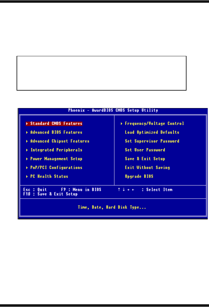
865GV Micro 775
3
1 Main Menu
Once you enter Award BIOS™ CMOS Setup Utility, the Main Menu will appear on the
screen. The Main Menu allows you to select from several setup functions. Use the arrow
keys to select among the items and press <Enter> to accept and enter the sub-menu.
Figure 1. Main Menu
Standard CMOS Features
This submenu contains industry standard configurable options.
Advanced BIOS Features
This submenu allows you to configure enhanced features of the BIOS.
Advanced Chipset Features
This submenu allows you to configure special chipset features.
WARNING
The information about BIOS defaults on this manual (Figure
1,2,3,4,5,6,7,8,9) is just only for reference, please refer to the BIOS
installed on board, for update information.
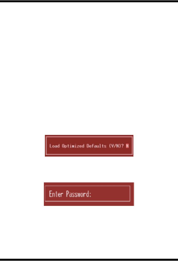
865GV Micro 775
4
Integrated Peripherals
This submenu allows you to configure certain IDE hard drive options and Programmed
Input/ Output features.
Power Management Setup
This submenu allows you to configure the power management features.
PnP/PCI Configurations
This submenu allows you to configure certain “Plug and Play” and PCI options.
PC Health Status
This submenu allows you to monitor the hardware of your system.
Frequency Control
This submenu allows you to change CPU Vcore Voltage and CPU/PCI clock. (However,
this function is strongly recommended not to use. Not properly change the voltage
and clock may cause CPU or M/B damage!)
Load Optimized Defaults
This selection allows you to reload the BIOS when the system is having problems
particularly with the boot sequence. These configurations are factory settings optimized
for this system. A confirmation message will be displayed before defaults are set.
Set Supervisor Password
Setting the supervisor password will prohibit everyone except the supervisor from making
changes using the CMOS Setup Utility. You will be prompted with to enter a password.
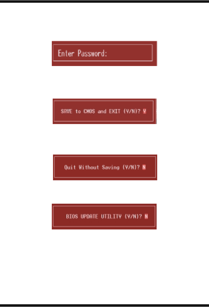
865GV Micro 775
5
Set User Password
If the Supervisor Password is not set, then the User Password will function in the same way
as the Supervisor Password. If the Supervisor Password is set and the User Password is
set, the “User” will only be able to view configurations but will not be able to change them.
Save & Exit Setup
Save all configuration changes to CMOS(memory) and exit setup. Confirmation message
will be displayed before proceeding.
Exit Without Saving
Abandon all changes made during the current session and exit setup. Confirmation message
will be displayed before proceeding.
Upgrade BIOS
This submenu allows you to upgrade bios.
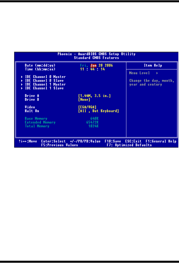
865GV Micro 775
6
2 Standard CMOS Features
The items in Standard CMOS Setup Menu are divided into 10 categories. Each category
includes no, one or more than one setup items. Use the arrow keys to highlight the item and
then use the<PgUp> or <PgDn> keys to select the value you want in each item.
Figure 2. Standard CMOS Setup

865GV Micro 775
7
Main Menu Selections
This table shows the selections that you can make on the Main Menu.
Item Options Description
Date mm : dd : yy Set the system date. Note
that the ‘Day’ automatically
changes when you set the
date.
Time hh : mm : ss Set the system internal
clock.
IDE Primary Master Options are in its sub
menu. Press <Enter> to enter the
sub menu of detailed
options
IDE Primary Slave Options are in its sub
menu. Press <Enter> to enter the
sub menu of detailed
options.
IDE Secondary Master Options are in its sub
menu. Press <Enter> to enter the
sub menu of detailed
options.
IDE Secondary Slave Options are in its sub
menu. Press <Enter> to enter the
sub menu of detailed
options.
Drive A
Drive B
360K, 5.25 in
1.2M, 5.25 in
720K, 3.5 in
1.44M, 3.5 in
2.88M, 3.5 in
None
Select the type of floppy
disk drive installed in your
system.
Video EGA/VGA
CGA 40
CGA 80
MONO
Select the default video
device.

865GV Micro 775
8
Item Options Description
Halt On All Errors
No Errors
All, but Keyboard
All, but Diskette
All, but Disk/ Key
Select the situation in which
you want the BIOS to stop
the POST process and
notify you.
Base Memory N/A Displays the amount of
conventional memory
detected during boot up.
Extended Memory N/A Displays the amount of
extended memory detected
during boot up.
Total Memory N/A Displays the total memory
available in the system.
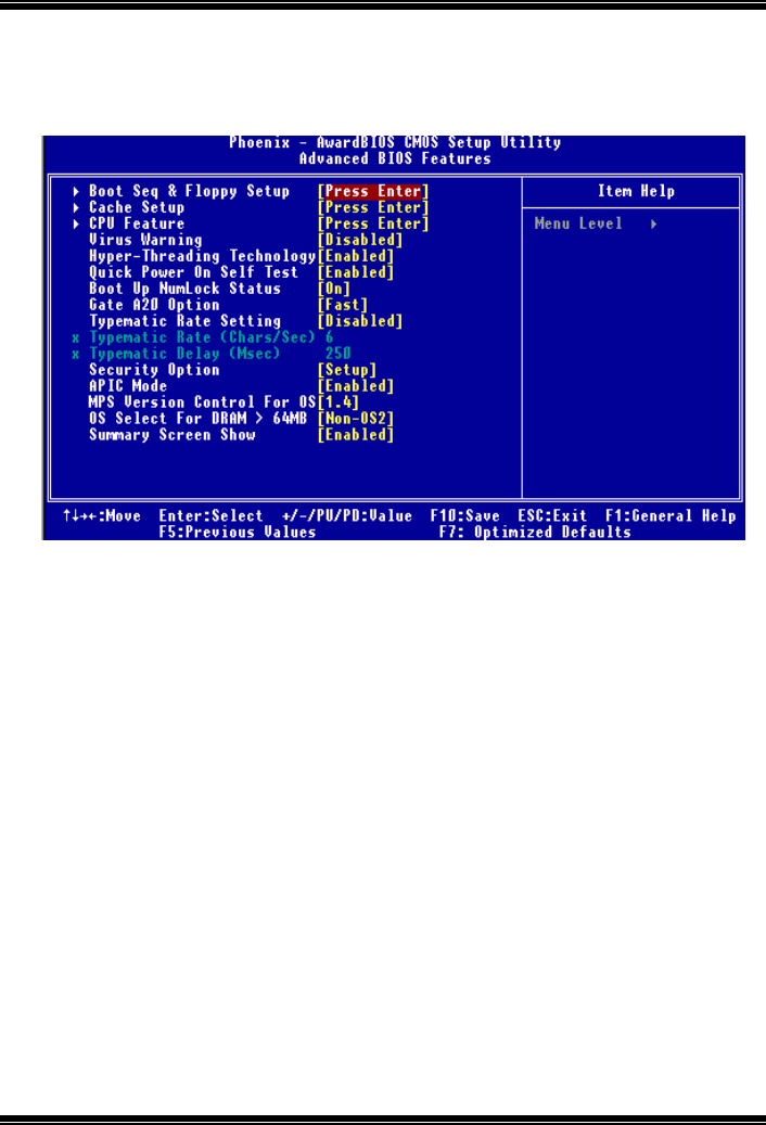
865GV Micro 775
9
3 Advanced BIOS Features
Figure 3. Advanced BIOS Setup
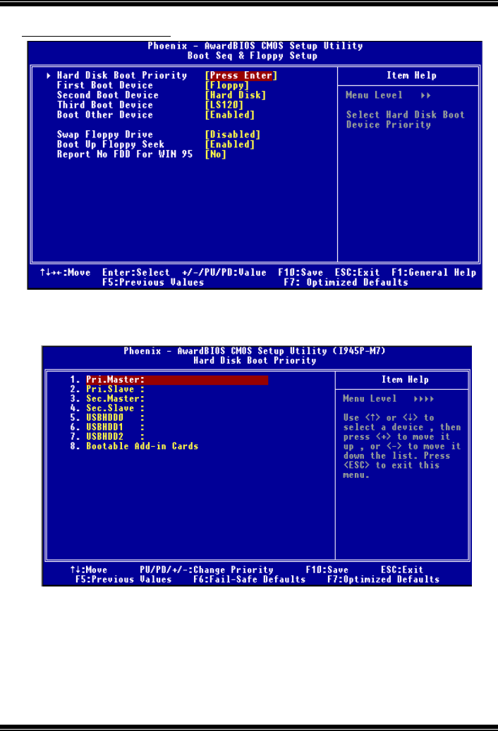
865GV Micro 775
10
Boot Seq & Floppy Setup
Hard Disk Boot Priority
These BIOS attempt to arrange the Hard Disk boot sequence automatically.
This will depend on which Hard Disk is installed.
The Choices: Pri. Master, Pri. Slave, Sec. Master, Sec, Slave, USB HDD0, USB
HDD1, USB HDD2, and Bootable Add-in Cards.
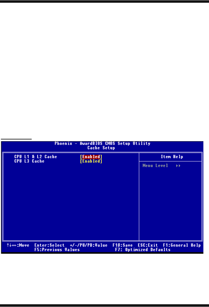
865GV Micro 775
11
First/ Second/ Third/ Boot Other Device
These BIOS attempt to load the operating system from the device in the sequence
selected in these items.
The Choices: Floppy, LS120, HDD-0, SCSI, CDROM, HDD-1, HDD-2, HDD-3,
ZIP100, LAN, HPT370, Disabled, Enabled.
Swap Floppy Drive
For systems with two floppy drives, this option allows you to swap logical drive
assignments.
The Choices: Disabled (default), Enabled.
Boot Up Floppy Seek
Enabling this option will test the floppy drives to determine if they have 40 or 80
tracks. Disabling this option reduces the time it takes to boot-up.
The Choices: Disabled, Enabled (default).
Report NO FDD for Win95
This item allows you to select YES/NO to Report NO FDD for Win95.
The Choices: NO (default),Yes.
Cache Setup
CPU L1&L2 Cache
Depending on the CPU/chipset in use, you may be able to increase memory
access time with this option.
Enabled (default) Enable cache.
Disabled Disable cache.
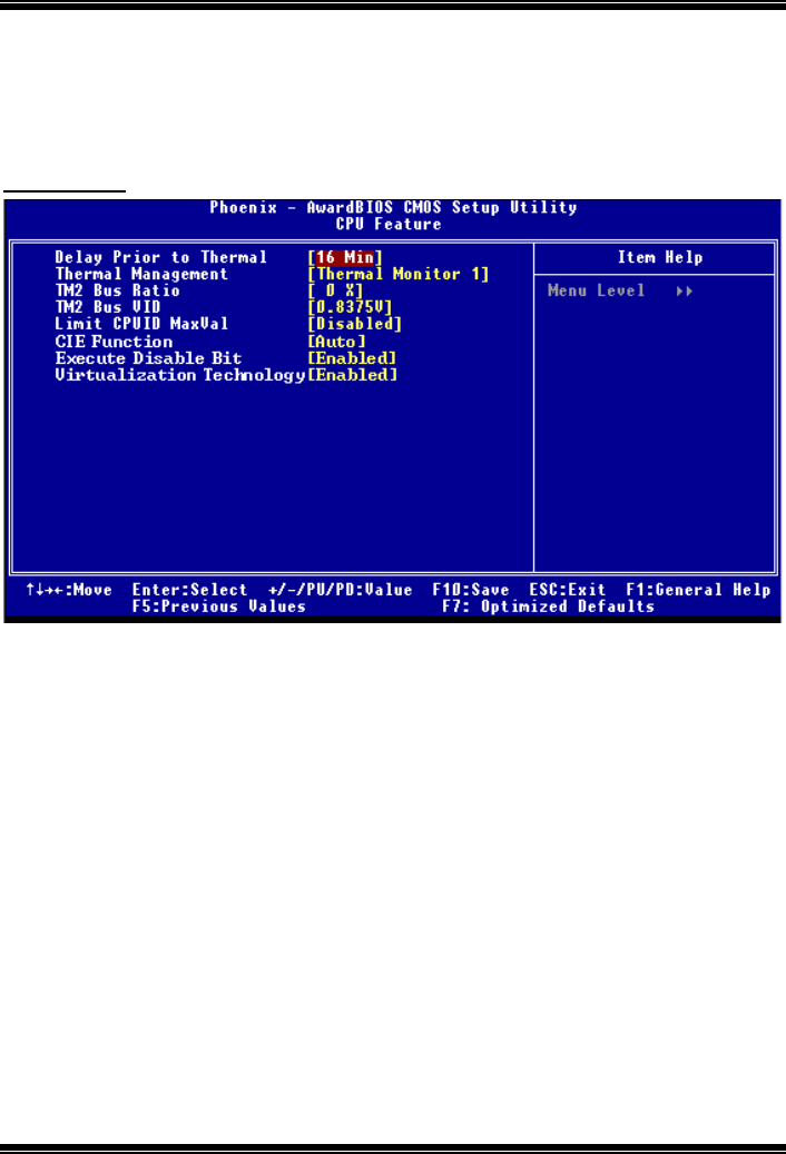
865GV Micro 775
12
CPU L3 Cache
Depending on the CPU/chipset in use, you may be able to increase memory
access time with this option.
Enabled (default) Enable cache.
Disabled Disable cache.
CPU Feature
Delay Prior to Thermal
Set this item to enable the CPU Thermal function to engage after the specified
time.
The Choices: 4 Min, 8 Min, 16Min (default), 32 Min.
Thermal Management
Allows you to choose the thermal management of your monitor.
The Choices: Thermal Monitor 1 (default), Thermal Monitor2.
TM2 Bus Ratio
Represents the frequency. Bus ratio of the throttled performance state that will
be initiated when the on-die sensor gose from not hot to hot.
The Choices: 0X (default).
Min= 0,Max= 255 ,Key in a DEC number.
TM2 Bus VID
Represents the voltage of the throttled performance state that will be initiated
when the on-die sensor gose from not hot to hot.(Min=0.8375,Max=1.6000.)
The Choices: 0.8375 (default).

865GV Micro 775
13
Limit CPU ID Max Val
Set limit CPU ID maximun vale to 3, it should be disabled for WinXP.
The Choices: Disabled (default), Enabled.
C1E Function
This item allows you to configure the Enhanced Halt State (C1E) function, which
may reduce the power consumption of your system when the system is idle.
The Choices: Auto (default),Disabled.
Execute Disable Bit
This item allows you to configure the Execute Disabled Bit function, which
protects your system from buffer overflow attacks.
The Choices: Enabled (default), Disabled.
Virtualization Technology
Virtualization Technology can virtually separate your system resource into
several parts, thus enhance the performance when running virtual machines or
multi interface systems.
The Choices: Enabled (default), Disabled.
Virus Warning
This option allows you to choose the Virus Warning feature that is used to protect the IDE
Hard Disk boot sector. If this function is enabled and an attempt is made to write to the
boot sector, BIOS will display a warning message on the screen and sound an alarm beep.
Enabled Virus protection is activated.
Disabled (default) Virus protection is disabled.
Hyper-Threading Technology
This option allows you to enable or disabled CPU Hyper-Threading. Enabled for
Windows XP and Linux 2.4.x (OS optimized for Hyper Threading Technology. Disabled
for other OS (OS not optimized for Hyper Threading Technology.
The Choices: Enabled (default), Disabled.
Quick Power On Self Test
Enabling this option will cause an abridged version of the Power On Self-Test (POST) to
execute after you power up the computer.
Disabled Normal POST.
Enabled (default) Enable quick POST.
Boot Up NumLock Status
Selects the NumLock. State after power on.
On (default) Numpad is number keys.
Off Numpad is arrow keys.
Gate A20 Option

865GV Micro 775
14
Select if chipset or keyboard controller should control Gate A20.
Normal A pin in the keyboard controller controls Gate A20.
Fast (default) Lets chipset control Gate A20.
Typematic Rate Setting
When a key is held down, the keystroke will repeat at a rate determined by the keyboard
controller. When enabled, the typematic rate and typematic delay can be configured.
The Choices: Disabled (default), Enabled.
Typematic Rate (Chars/Sec)
Sets the rate at which a keystroke is repeated when you hold the key down.
The Choices: 6 (default), 8,10,12,15,20,24,30.
Typematic Delay (Msec)
Sets the delay time after the key is held down before it begins to repeat the keystroke.
The Choices: 250 (default), 500, 750, 1000.
Security Option
This option will enable only individuals with passwords to bring the system online and/or
to use the CMOS Setup Utility.
System A password is required for the system to boot and is also required to
access the Setup Utility.
Setup (default) A password is required to access the Setup Utility only.
This will only apply if passwords are set from the Setup main menu.
APIC Mode
Selecting Enabled enables APIC device mode reporting from the BIOS to the operating
system.
The Choices: Enabled (default), Disabled.
MPS Version Control For OS
The BIOS supports version 1.1 and 1.4 of the Intel multiprocessor specification.
Select version supported by the operation system running on this computer.
The Choices: 1.4 (default), 1.1.
OS Select For DRAM > 64MB
A choice other than Non-OS2 is only used for OS2 systems with memory exceeding 64MB.
The Choices: Non-OS2 (default), OS2.
Summary Screen Show
This item allows you to enable/disable the summary screen. Summary screen means
system configuration and PCI device listing.
The choices: Enabled (default)., Disabled
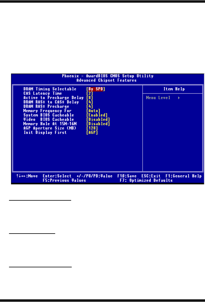
865GV Micro 775
15
4 Advanced Chipset Features
This submenu allows you to configure the specific features of the chipset installed on your
system. This chipset manage bus speeds and access to system memory resources, such as
DRAM. It also coordinates communications with the PCI bus. The default settings that came
with your system have been optimized and therefore should not be changed unless you are
suspicious that the settings have been changed incorrectly.
Figure 4. Advanced Chipset Setup
DRAM Timing Selectable
When synchronous DRAM is installed, the number of clock cycles of CAS latency depends
on the DRAM timing.
The Choices: By SPD (default), Manual.
CAS Latency Time
When synchronous DRAM is installed, the number of clock cycles of CAS latency depends
on the DRAM timing.
The Choices: 2 (default), 2.5, 3.
Active to Precharge Delay
This item controls the number of DRAM clocks to activate the precharge delay.
The Choices: 8 (default), 7, 6, 5.

865GV Micro 775
16
DRAM RAS# to CAS# Delay
This field let you insert a timing delay between the CAS and RAS strobe signals, used
when DRAM is written to, read from, or refreshed. Fast gives faster performance; and slow
gives more stable performance. This field applies only when synchronous DRAM is
installed in the system.
The Choices: 4 (default), 3, 2.
DRAM RAS# Precharge
If an insufficient number of cycle is allowed for RAS to accumulate its charge before
DRAM refresh, the refresh may be incomplete, and the DRAM may fail to retain data. Fast
gives faster performance; and Slow gives more stable performance. This field applies only
when synchronous DRAM is installed in the system.
The Choices: 4 (default), 3, 2.
Memory Frequency For
This item allows you to select the Memory Frequency.
The Choices: Auto (default), DDR266, DDR300, DDR320, DDR400.
System BIOS Cacheable
Selecting Enabled allows you caching of the system BIOS ROM at F0000h~FFFFFh,
resulting a better system performance. However, if any program writes to this memory area,
a system error may result.
The Choices: Enabled (default), Disabled.
Video BIOS Cacheable
Select Enabled allows caching of the video BIOS, resulting a better system performance.
However, if any program writes to this memory area, a system error may result.
The Choices: Disabled (default).d, Enabled
Memory Hole At 15M-16M
You can reserve this area of system memory for ISA adapter ROM. When this area is
reserved it cannot be cached. The user information of peripherals that need to use this area
of system memory usually2 discussed their memory requirements.
The Choices: Disabled (default), Enabled.
AGP Aperture Size (MB)
Select the size of the Accelerated Graphics Port (AGP) aperture. The aperture is a portion
of the PCI memory address range dedicated for graphics memory address space. Host
cycles that hit the aperture range are forwarded to the AGP without any translation.
The Choices: 64, 4, 8, 16, 32, 128 (default), 256.

865GV Micro 775
17
Init Display First
This item allows you to decide to active whether PCI Slot or on-chip VGA first.
The Choices: AGP (default), PCI Slot.
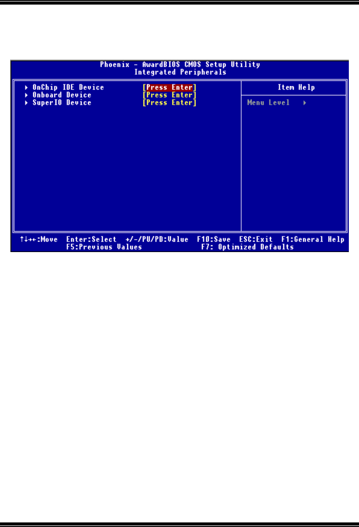
865GV Micro 775
18
5 Integrated Peripherals
Figure 5. Integrated Peripherals
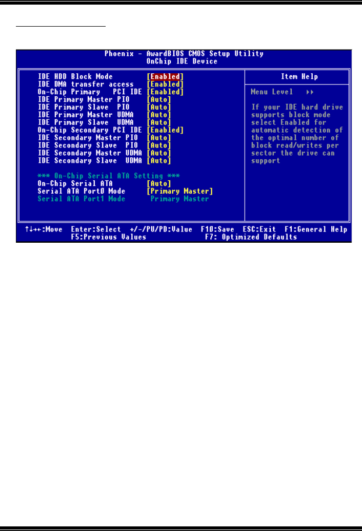
865GV Micro 775
19
Onboard IDE Device
Press Enter to configure the onboard IDE Controllers.
IDE HDD Block Mode
Block mode is also called block transfer, multiple commands, or multiple sector
read / write. If your IDE hard drive supports block mode (most new drives do),
select Enabled for automatic detection of the optimal number of block mode
(most new drives do), select Enabled for automatic detection of the optimal
number of block read / write per sector where the drive can support.
The Choices: Enabled (default), Disabled.
IDE DMA Transfer Access
This item allows you to enable or disable the IDE transfer access.
The Choices: Enabled (default), Disabled.
On-Chip Primary/ Secondary PCI IDE
This item allows you to enable or disable the primary/ secondary IDE Channel.
The Choices: Enabled (default), Disabled.
Primary / Secondary /Master / Slave PIO
The IDE PIO (Programmed Input / Output) fields let you set a PIO mode (0-4) for
each of the IDE devices that the onboard IDE interface supports. Modes 0 to 4
will increased performance progressively. In Auto mode, the system
automatically determines the best mode for each device.
The Choices: Auto (default), Mode0, Mode1, Mode2, Mode3, Mode4.

865GV Micro 775
20
Primary / Secondary /Master / Slave UDMA
Ultra DMA/100 functionality can be implemented if it is supported by the IDE
hard drives in your system. As well, your operating environment requires a DMA
driver (Windows 95 OSR2 or a third party IDE bus master driver). If your hard
drive and your system software both support Ultra DMA/100, select Auto to
enable BIOS support.
The Choices: Auto (default), Disabled.
On-Chip Serial SATA
This item allows you to choose:
Disabled: disabled SATA Controller.
Auto: auto arrange by BIOS.
Combined Mode: PATA and SATA are combined max of 2 IDE drivers in each
channel.
Enhanced Mode: enabled both SATA and PATA max of 6 IDE drivers are
supported.
SATA Only: SATA is operating in legacy mode.
The Choices: Auto (default), Combined Mode, Enhanced Mode, SATA only.
Serial ATA Port 0/Port1 Mode
The Choices: Primary Master (default).
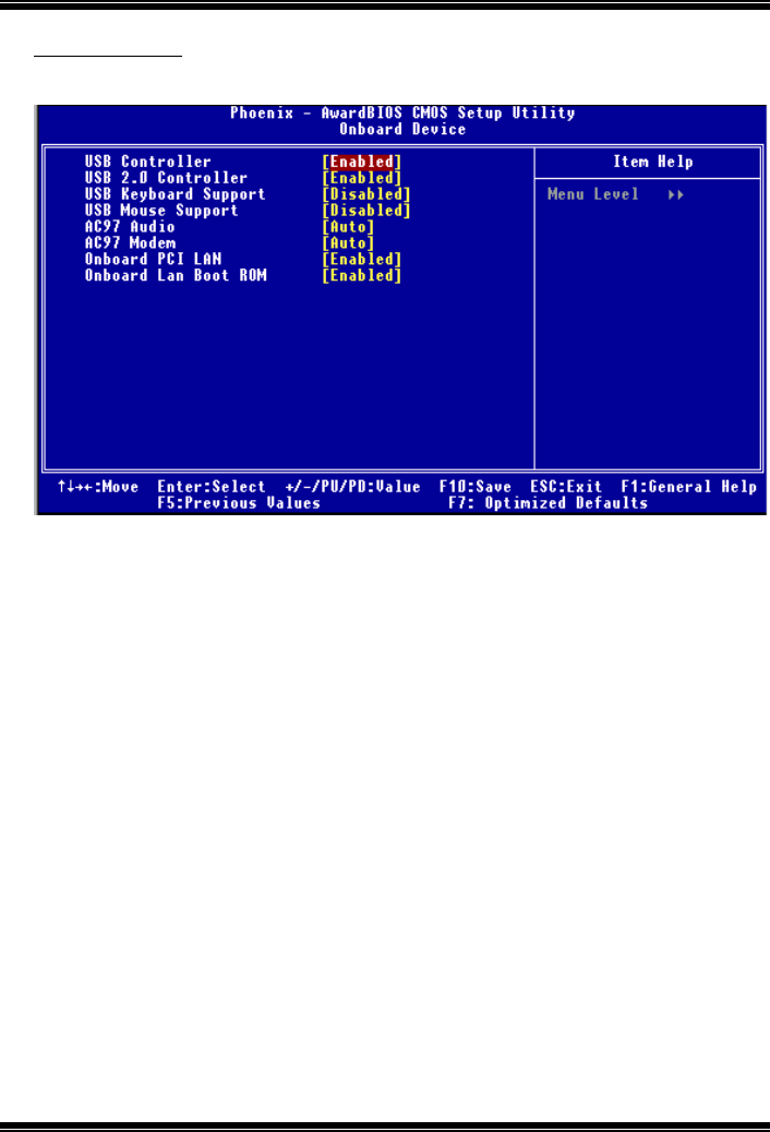
865GV Micro 775
21
Onboard Device
Press Enter to configure the onboard Device.
USB Controller
Select Enabled if your system contains a Universal Serial Bus (USB) controller
and you have USB peripherals.
The Choices: Enabled (default), Disabled
USB 2.0 Controller
This entry is to enabled/ disabled EHCI controller only. This BIOS itself may/
may not have high speed USB support. If the BIOS has high speed USB
support built in, the support will automatically turn on, when high speed device
were attached.
The Choices: Enabled (default).
USB Keyboard Support
This item allows you to enable or disable the USB Keyboard Legacy Support.
Enabled Enable USB Keyboard Support.
Disabled (default) Disable USB Keyboard Support.
USB Mouse Support
This item allows you to enable or disable the USB Mouse Legacy Support.
Enabled Enable USB Mouse Support.
Disabled (default) Disable USB Mouse Support.
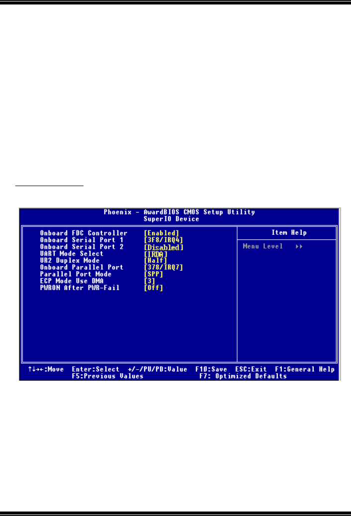
865GV Micro 775
22
AC97 Audio
This item allows you to decide to enable/ disable to AC97 Audio support.
The Choices: Auto (default), Disabled.
AC97 Modem
This item allows you to decide to enable/ disable to AC97 Modem support.
The Choices: Auto (default), Disabled.
Onboard PCI LAN
This item allows you to enable or disable the Onboard PCI LAN.
The Choices: Enabled (default), Disabled.
Onboard LAN Boot ROM
Decide whether to invoke the boot ROM of the onboard LAN chip.
The Choices: Enabled (default), Disabled.
Super IO Device
Press Enter to configure the Super I/O Device.
Onboard FDC Controller
Select Enabled if your system has a floppy disk controller (FDC) installed on the
system board and you wish to use it. If install and FDC or the system has no
floppy drive, select Disabled in this field.
The Choices: Enabled (default), Disabled.
Onboard Serial Port 1
Select an address and corresponding interrupt for the first and second serial ports.
The Choices: 3F8/IRQ4 (default), Disabled, Auto, 2F8/IRQ3,
3E8/IRQ4, 2E8/IRQ3.

865GV Micro 775
23
Onboard Serial Port 2
Select an address and corresponding interrupt for the first and second serial ports
The Choices: 2F8/IRQ3 (default), Disabled, Auto, 3F8/IRQ4, 3E8/IRQ4,
2E8/IRQ3.
UART Mode Select
This item allows you to determine which Infrared (IR) function of onboard I/O
chip.
The Choices: Normal (default), ASKIR, IrDA, SCR .
UR2 Duplex Mode
Select the value required by the IR device connected to the IR port. Full-duplex
mode permits simultaneous two-direction transmission. Half-duplex mode
permits transmission in one direction only at a time.
The Choices: Half (default), Full.
Onboard Parallel Port
This item allows you to determine access onboard parallel port controller with
which I/O Address.
The Choices: 378/IRQ7 (default), 278/IRQ5, 3BC/IRQ7, Disabled.
Parallel Port Mode
The default value is SPP.
SPP (default) Using Parallel port as Standard Printer Port.
EPP Using Parallel port as Enhanced Parallel Port.
ECP Using Parallel port as Extended Capabilities Port.
ECP+EPP Using Parallel port as ECP & EPP mode.
ECP Mode Use DMA
Select a DMA Channel for the port.
The Choices: 3 (default), 1.
Power After Power Fail
This setting specifies whether your system will reboot after a power fail or
interrupts occurs.
Off Leaves the computer in the power off state.
On Reboots the computer.
Former-Sts Restores the system to the status before power failure or
interrupt occurs.
The Choices: Off (default), On, Former-Sts.
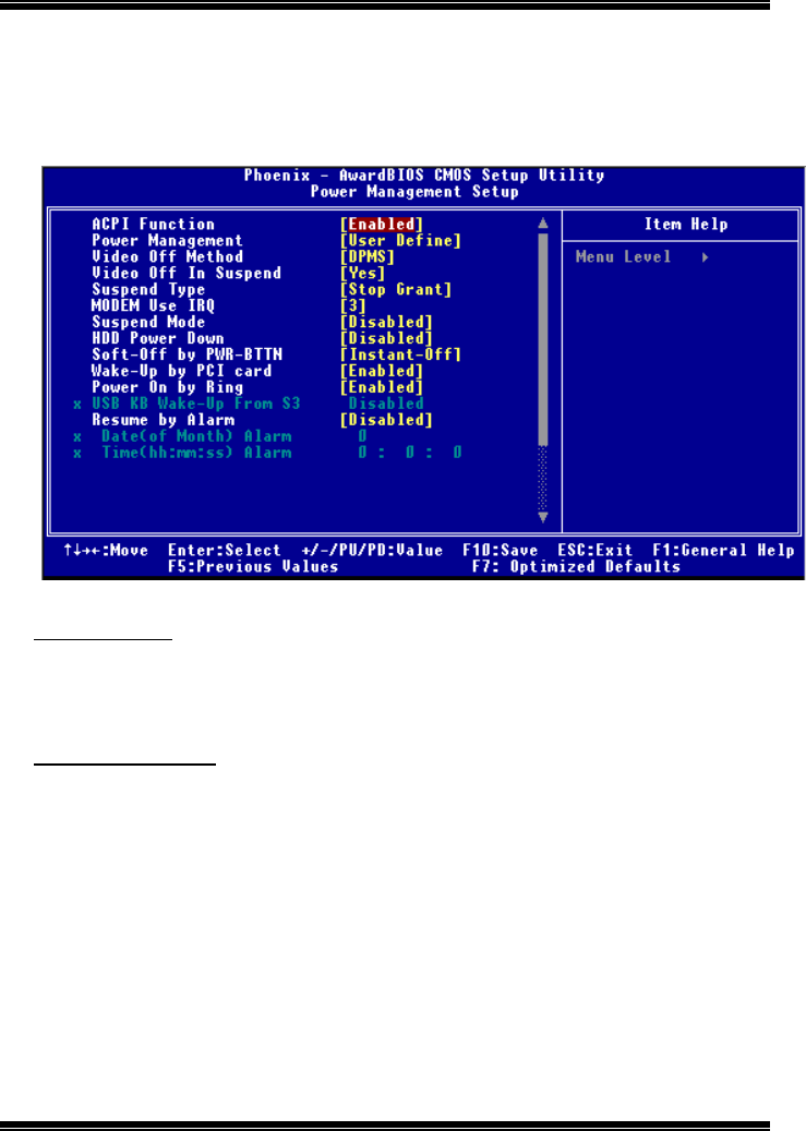
865GV Micro 775
24
6 Power Management Setup
The Power Management Setup Menu allows you to configure your system to utilize energy
conservation and power up/power down features.
Figure 6. Power Management Setup
ACPI Function
This item displays the status of the Advanced Configuration and Power Management
(ACPI).
The Choices: Enabled (default), Disabled.
Power Management
This category allows you to select the type (or degree) of power saving and is directly
related to the following modes:
1.HDD Power Down.
2.Doze Mode.
3.Suspend Mode.
There are four options of Power Management, three of which have fixed mode settings
Min. Saving
Minimum power management.
Doze Mode = 1 hr.
Standby Mode = 1 hr
Suspend Mode = 1 hr.

865GV Micro 775
25
HDD Power Down = 15 min
Max Saving
Maximum power management only available for sl CPU’s.
Doze Mode = 1 min
Standby Mode = 1 min.
Suspend Mode = 1 min.
HDD Power Down = 1 min.
User Defined (default)
Allows you to set each mode individually.
When not disabled, each of the ranges are from 1 min. to 1 hr. except for HDD
Power Down which ranges from 1 min. to 15 min. and disable.
Video Off Method
This option determines the manner in which the monitor is goes blank.
V/H SYNC+Blank
This selection will cause the system to turn off the vertical and horizontal
synchronization ports and write blanks to the video buffer.
Blank Screen
This option only writes blanks to the video buffer.
DPMS (default)
Initial display power management signaling.
Video Off In Suspend
This determines the manner in which the monitor is blanked.
The Choices: Yes (default), No.
Suspend Type
Select the Suspend Type.
The Choices: Stop Grant (default), PwrOn Suspend.
MODEM Use IRQ
This determines the IRQ, which can be applied in MODEM use.
The Choices:3 (default)/ 4 / 5 / 7 / 9 / 10 / 11 / NA.

865GV Micro 775
26
Suspend Mode
When enabled and after the set time of system inactivity, all devices except the CPU will be
shut off.
The Choices: Disabled (default), 1Min, 2Min, 4Min, 8Min, 12Min, 20Min, 30Min, 40Min,
1Hour.
HDD Power Down
When enabled and after the set time of system inactivity, the hard disk drive will be
powered down while all other devices remain active.
The Choices: Disabled (default), 1Min, 2Min, 3Min, 4Min, 5Min, 6Min, 7Min, 8Min,
9Min, 10Min, 11Min, 12Min, 13Min, 14Min, 15Min.
.
Soft-Off by PWR-BTTN
Pressing the power button for more than 4 seconds forces the system to enter the
Soft-Off state when the system has “hung.”
The Choices: Delay 4 Sec, Instant-Off (default).
Wake-Up by PCI card
When you select Enable, a PME signal from PCI card returns the system to Full On state.
The Choices: Enabled (default)., Disabled
Power On by Ring
An input signal on the serial Ring Indicator (RI) line (in other words, an incoming call on
the modem) awakens the system from a soft off state.
The Choices: Enabled (default), Disabled
Resume by Alarm
This function is for setting date and time for your computer to boot up. During Disabled,
you cannot use this function. During Enabled,Choose the Date and Time.
The Choices: Disabled (default), Enabled.
Date (of Month) Alarm
You can choose which month the system will boot up.
Time (hh:mm:ss) Alarm
You can choose shat hour, minute and second the system will boot up.
Note: If you have change the setting, you must let the system boot up until it goes to
the operating system, before this function will work.
Reload Timer Events
Primary/Secondary IDE 0/1
You can select to enable or disable Primary or Secondary RAID 0 or
RAID 1 function under this item.

865GV Micro 775
27
The Choices: Disabled (default), Enabled.
FDD, COM, LPT Port
You can select to enable or disable FDD, COM, and LPT port under
this item.
The Choices: Disabled (default), Enabled.
PCI PIRQ [A-D]#
You can select to enable or disable PCI PIRQ [A-D]# under this item.
The Choices: Disabled (default), Enabled.
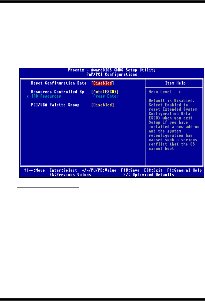
865GV Micro 775
28
7 PnP/PCI Configurations
This section describes configuring the PCI bus system. PCI, or Personal Computer
Interconnect, is a system which allows I/O devices to operate at speeds nearing the speed of
the CPU itself uses when communicating with its own special components. This section
covers some very technical items and it is strongly recommended that only experienced
users should make any changes to the default settings.
Figure 7. PnP/PCI Configurations
Reset Configuration Data
The system BIOS supports the PnP feature which requires the system to record which
resources are assigned and protects resources from conflict. Every peripheral device has a
node, which is called ESCD. This node records which resources are assigned to it. The
system needs to record and update ESCD to the memory locations. These locations (4K)
are reserved in the system BIOS. If the Disabled (default) option is chosen, the system‘s
ESCD will update only when the new configuration varies from the last one. If the Enabled
option is chosen, the system is forced to update ESCDs and then is automatically set to the
“Disabled” mode.
The above settings will be shown on the screen only if “Manual” is chosen for the resources
controlled by function.
Legacy is the term, which signifies that a resource is assigned to the ISA Bus and provides
non-PnP ISA add-on cards. PCI / ISA PnP signifies that a resource is assigned to the PCI
Bus or provides for ISA PnP add-on cards and peripherals.
The Choices: Disabled (default), Enabled.

865GV Micro 775
29
Resources Controlled By
By Choosing “Auto(ESCD)” (default), the system BIOS will detect the system resources
and automatically assign the relative IRQ and DMA channel for each peripheral.By
Choosing “Manual”, the user will need to assign IRQ & DMA for add-on cards. Be sure
that there are no IRQ/DMA and I/O port conflicts.
IRQ Resources
This submenu will allow you to assign each system interrupt a type, depending on the type
of device using the interrupt. When you press the “Press Enter” tag, you will be directed to
a submenu that will allow you to configure the system interrupts. This is only
configurable when “Resources Controlled By” is set to “Manual”.
IRQ-3 assigned to PCI Device
IRQ-4 assigned to PCI Device
IRQ-5 assigned to PCI Device
IRQ-7 assigned to PCI Device
IRQ-9 assigned to PCI Device
IRQ-10 assigned to PCI Device
IRQ-11 assigned to PCI Device
IRQ-12 assigned to PCI Device
IRQ-14 assigned to PCI Device
IRQ-15 assigned to PCI Device
PCI / VGA Palette Snoop
Choose Disabled or Enabled. Some graphic controllers which are not VGA compatible
take the output from a VGA controller and map it to their display as a way to provide boot
information and VGA compatibility.
However, the color information coming from the VGA controller is drawn from the palette
table inside the VGA controller to generate the proper colors, and the graphic controller
needs to know what is in the palette of the VGA controller. To do this, the non-VGA
graphic controller watch for the Write access to the VGA palette and registers the snoop
data. In PCI based systems, where the VGA controller is on the PCI bus and a non-VGA
graphic controller is on an ISA bus, the Write Access to the palette will not show up on the
ISA bus if the PCI VGA controller responds to the Write.
In this case, the PCI VGA controller should not respond to the Write, it should only snoop
the data and permit the access to be forwarded to the ISA bus. The non-VGA ISA graphic
controller can then snoop the data on the ISA bus. Unless you have the above situation,
you should disable this option.
Disabled (default) Disable the function.
Enabled Enable the function.
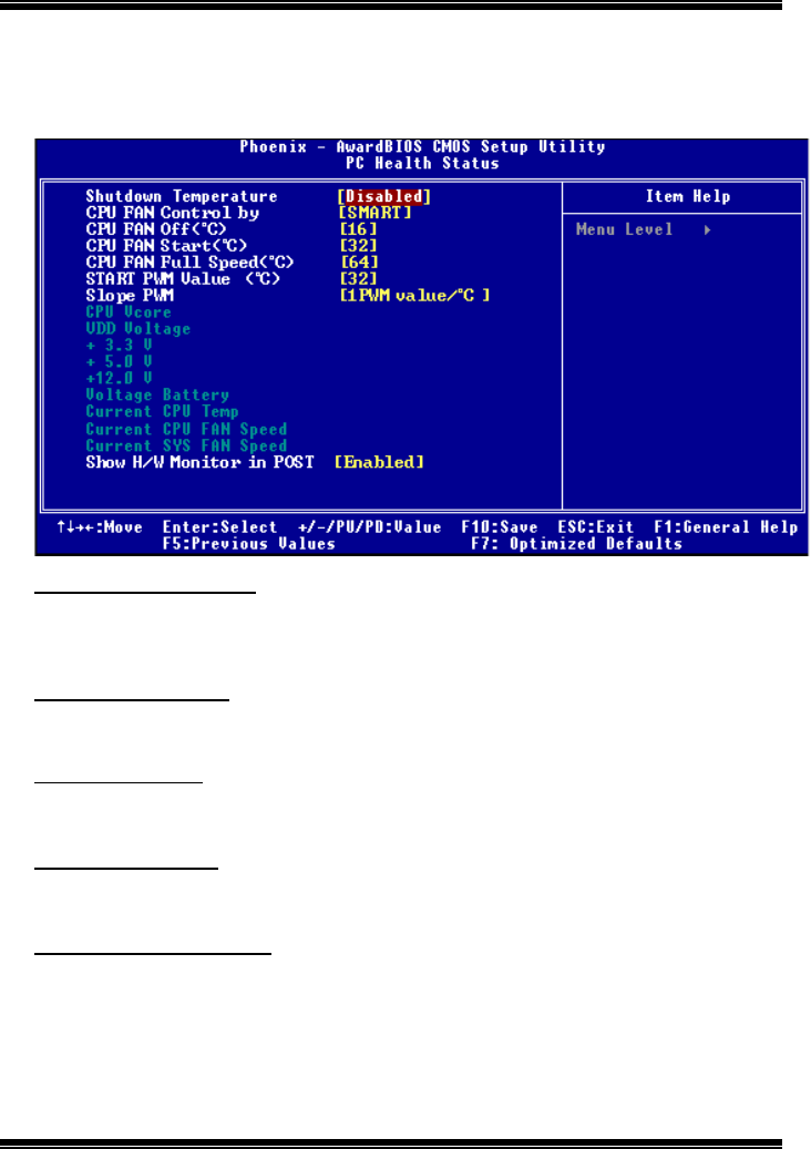
865GV Micro 775
30
8 PC Health Status
Figure 8. PC Health Status
Shutdown Temperature
This item allows you to set up the CPU shutdown Temperature. This item is only effective
under Windows 98 ACPI mode.
The Choices: 60°C/140°C, 65°C/149°F, 70°C/140°C, Disabled (default).
SYS FAN Control by
Choose “smart” to reduce the noise caused by the System FAN.
The Choices: SMART (default), Always On.
CPU Fan Off<℃
℃℃
℃>
If the CPU Temperature is lower than the set value, FAN will turn off.
The Choices: 16 (default).
CPU Fan Start<℃
℃℃
℃>
CPU fan starts to work under smart fan function when arrive this set value.
The Choices: 32(default).
CPU Fan Full speed <℃
℃℃
℃>
When CPU temperature is reach the set value, the CPU fan will work under Full Speed.
The Choices: 52(default).

865GV Micro 775
31
Start PWM Value
When CPU temperature arrives to the set value, the CPU fan will work under Smart Fan
Function mode. The range is from 0~127, with an interval of 1.
The Choices: 32 (default).
Slope PWM
Increasing the value of slope PWM will raise the speed of CPU fan.
The Choices: 1 PWM Value/℃
℃℃
℃(default), 2 PWM Value/℃, 4 PWM Value/℃, 8 PWM
Value/℃,16 PWM Value/℃,32 PWM Value/℃, 64PWM Value/℃.
CPU Vcore,VDDPVoltage,+3.3V,+5.0V,+12.0V,Voltage Battery
Detect the system’s voltage status automatically.
Current CPU Temp
Show you the current CPU temperature.
Current CPU FAN Speed
This field displays the current CPUFAN speed.
Current SYS FAN Speed
This field displays the current speed SYSTEM fan.
Show H/W Monitor in POST
If you computer contains a monitoring system, it will show PC health status during POST
stage. The item offers several different delay times.
The Choices: Enabled (default), Disabled.
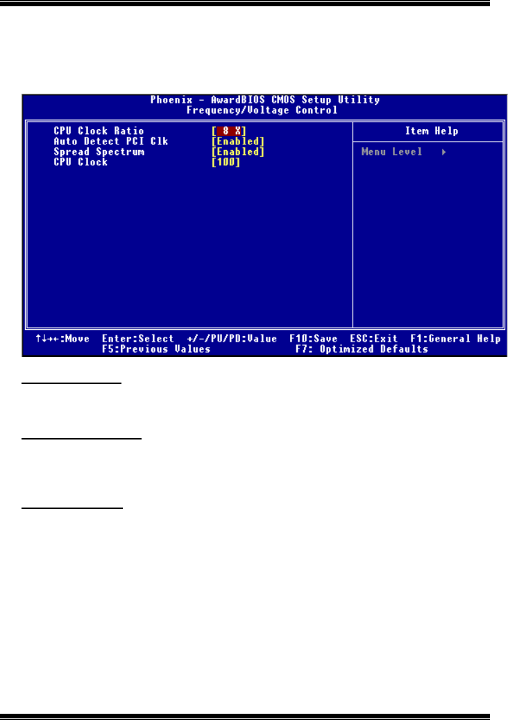
865GV Micro 775
32
9 Frequency /Voltage Control
Figure 9. Frequency Control
CPU Clock Ratio
The Choices: 8 X (default).
Min= 8,Max= 50,Key in a DEC number.
Auto Detect PCI Clk
This item allows you to enable / disable auto Detect PCI Clock.
The Choices: Enabled (default), Disabled.
Spread Spectrum
This item allows you to enable / disable spectrum for all clock.
The Choices: Enabled (default), Disabled.
865GV Micro 775
33
CPU Clock
This item allows you to select CPU Clock, and CPU over clocking.
The Choices: 100 (default).
Min= 100,Max= 255,Key in a DEC number.
If unfortunately, the system’s frequency that you are selected is
not functioning, there are two methods of booting-up the system.
Method 1: Clear the COMS data by setting the JCOMS1 ((2-3) closed))
as “ON” status. All the CMOS data will be loaded as
defaults setting.
Method 2: Press the <Insert> key and Power button simultaneously,
after that keep-on pressing the <Insert> key until the
power-on screen showed. This action will boot-up the
system according to FSB of the processor.
※ It’s strongly recommended to set CPU Vcore and clock in
default setting. If the CPU Vcore and clock are not in default
setting, it may cause CPU or M/B damage.
