Biostar B85Mg Owners Manual IB85D MHS_20130704
2014-07-31
: Biostar Biostar-B85Mg-Owners-Manual biostar-b85mg-owners-manual biostar pdf
Open the PDF directly: View PDF ![]() .
.
Page Count: 44

B85MG Setup Manual
FCC Information and Copyright
This equipment has been tested and found to comply with the limits of a Class B
digital device, pursuant to Part 15 of the FCC Rules. These limits are designed
to provide reasonable protection against harmful interference in a residential
installation. This equipment generates, uses, and can radiate radio frequency
energy and, if not installed and used in accordance with the instructions, may
cause harmful interference to radio communications. There is no guarantee that
interference will not occur in a particular installation.
The vendor makes no representations or warranties with respect to the contents
here and specially disclaims any implied warranties of merchantability or fitness
for any purpose. Further the vendor reserves the right to revise this publication
and to make changes to the contents here without obligation to notify any party
beforehand.
Duplication of this publication, in part or in whole, is not allowed without first
obtaining the vendor’s approval in writing.
The content of this user’s manual is subject to be changed without notice and we
will not be responsible for any mistakes found in this user’s manual. All the brand
and product names are trademarks of their respective companies.
Dichiarazione di conformità
sintetica
Ai sensi dell’art. 2 comma 3 del D.M.
275 del 30/10/2002
Si dichiara che questo prodotto è
conforme alle normative vigenti e
soddisfa i requisiti essenziali richiesti
dalle direttive
2004/108/CE, 2006/95/CE e
1999/05/CE
quando ad esso applicabili
Short Declaration of conformity
We declare this product is complying
with the laws in force and meeting all
the essential requirements as specified
by the directives
2004/108/CE, 2006/95/CE and
1999/05/CE
whenever these laws may be applied

Table of Contents
Chapter 1: Introduction ................................................. 1
1.1 Before You Start ................................................................................1
1.2 Package Checklist ............................................................................1
1.3 Motherboard Specifications .............................................................2
1.4 Rear Panel Connectors....................................................................3
1.5 Motherboard Layout..........................................................................4
Chapter 2: Hardware Installation .................................. 5
2.1 Install Central Processing Unit (CPU)............................................5
2.2 Install a Heatsink ...............................................................................7
2.3 Connect Cooling Fans......................................................................8
2.4 Install System Memory.....................................................................9
2.5 Expansion Slots...............................................................................10
2.6 Jumper Setting ................................................................................12
2.7 Headers & Connectors...................................................................13
Chapter 3: UEFI BIOS & Software ................................ 18
3.1 UEFI BIOS Setup ............................................................................18
3.2 BIOS Update....................................................................................18
3.3 Software............................................................................................22
Chapter 4: Useful Help ................................................. 31
4.1 Driver Installation.............................................................................31
4.2 AMI BIOS Beep Code.....................................................................32
4.3 Troubleshooting...............................................................................32
Appendix: Specifications in Other Languages .............. 34
Arabic.....................................................................................................................34
French ...................................................................................................................35
German .................................................................................................................36
Italian .....................................................................................................................37
Japanese...............................................................................................................38
Polish.....................................................................................................................39
Portuguese ...........................................................................................................40
Russian .................................................................................................................41
Spanish..................................................................................................................42

B85MG
1
CHAPTER 1: INTRODUCTION
1.1 Before You Start
Thank you for choosing our product. Before you start installing the
motherboard, please make sure you follow the instructions below:
Prepare a dry and stable working environment with sufficient
lighting.
Always disconnect the computer from power outlet before
operation.
Before you take the motherboard out from anti-static bag,
ground yourself properly by touching any safely grounded
appliance, or use grounded wrist strap to remove the static
charge.
Avoid touching the components on motherboard or the rear
side of the board unless necessary. Hold the board on the
edge, do not try to bend or flex the board.
Do not leave any unfastened small parts inside the case after
installation. Loose parts will cause short circuits which may
damage the equipment.
Keep the computer from dangerous area, such as heat
source, humid air and water.
The operating temperatures of the computer should be 0 to
45 degrees Celsius.
To avoid injury, be careful of:
Sharp pins on headers and connectors
Rough edges and sharp corners on the chassis
Damage to wires that could cause a short circuit
1.2 Package Checklist
; Serial ATA Cable x2
; Rear I/O Panel for ATX Case x1
; Installation Guide x1
; Fully Setup Driver DVD x1
Note: The package contents may be different due to the sales region or models in which it was
sold. For more information about the standard package in your region, please contact your dealer
or sales representative.

Motherboard Manual
2
1.3 Motherboard Specifications
Specifications
CPU Support
Socket 1150 for Intel® Core i7 / i5 / i3 / Pentium / Celeron processor
Maximum CPU TDP (Thermal Design Power): 95Watt
* Please refer to www.biostar.com.tw for CPU support list.
Chipset INTEL® B85
Memory
Supports Dual Channel DDR3 1066/ 1333/ 1600
2 x DDR3 DIMM Memory Slot, Max. Supports up to 16 GB Memory
Each DIMM supports non-ECC 512MB/ 1/ 2/ 4/ 8 GB DDR3 module
* Please refer to www.biostar.com.tw for Memory support list.
Storage INTEL® B85, Supports AHCI
4x SATA 6Gb/s Connector
LAN Realtek RTL 8111G
10/ 100/ 1000 Mb/s auto negotiation, Half / Full duplex capability
Audio Codec ALC892, 7.1 Channels, High Definition Audio
(2-channel output is from front audio header)
USB 4x USB 3.0 port (2 on rear I/Os and 2 via internal headers)
6x USB 2.0 port (2 on rear I/Os and 4 via internal headers)
Expansion Slots 2x PCIe 2.0 x1 Slot
1x PCIe 3.0 x16 Slot (x16)
Rear I/Os
1x PS/2 Mouse
1x PS/2 Keyboard
1x VGA Port
1x DVI Port
1x LAN port
2x USB 2.0 Port
2x USB 3.0 Port
3x Audio Jack
Internal I/Os
4x SATA 6.0Gb/s Connector
2x USB 2.0 Header (each header supports 2 USB 2.0 ports)
1x USB 3.0 Header (each header supports 2 USB 3.0 ports)
1x 4-Pin Power Connector
1x 24-Pin Power Connector
1x CPU Fan Connector
1x System Fan Connector
1x Front Panel Header
1x Front Audio Header
1x Clear CMOS Header
1x Serial Port Header
1x S/PDIF out Connector
1x Printer Port Header
Form Factor ATX Form Factor, 226 mm x 174 mm
OS Support Windows 7/ 8
Biostar reserves the right to add or remove support for any OS with or without notice.
B85MG
3
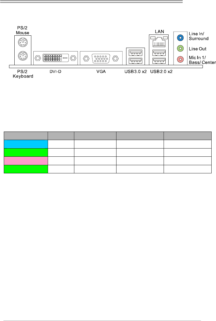
1.4 Rear Panel Connectors
Note1: DVI-D & VGA ports only work with an Intel® integrated Graphics Processor.
Note2: Maximum resolution:
DVI: 1920 x 1200 @60Hz
VGA: 1920 x 1200 @60Hz
Note3: To configure 7.1-channel audio, you have to use a chassis with HD front panel audio
module and enable the multi-channel audio feature through O.S. Audio Utility.
The 2/ 4/ 5.1/7.1-channel configuration
Port 2-channel 4-channel 5.1 channel 7.1 channel
Blue (Rear Panel) Line In Rear Speaker Out Rear Speaker Out Rear Speaker Out
Green (Rear Panel) Line Out Front Speaker Out Front Speaker Out Front Speaker Out
Pink (Rear Panel) Mic In Mic In Center/Subwoofer Out Center/Subwoofer Out
Green (Front Panel) -- -- -- Side Speaker Out
Motherboard Manual
4
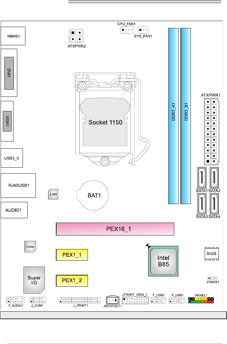
1.5 Motherboard Layout
Note: ■ represents the 1st pin.
B85MG
5
CHAPTER 2: HARDWARE INSTALLATION
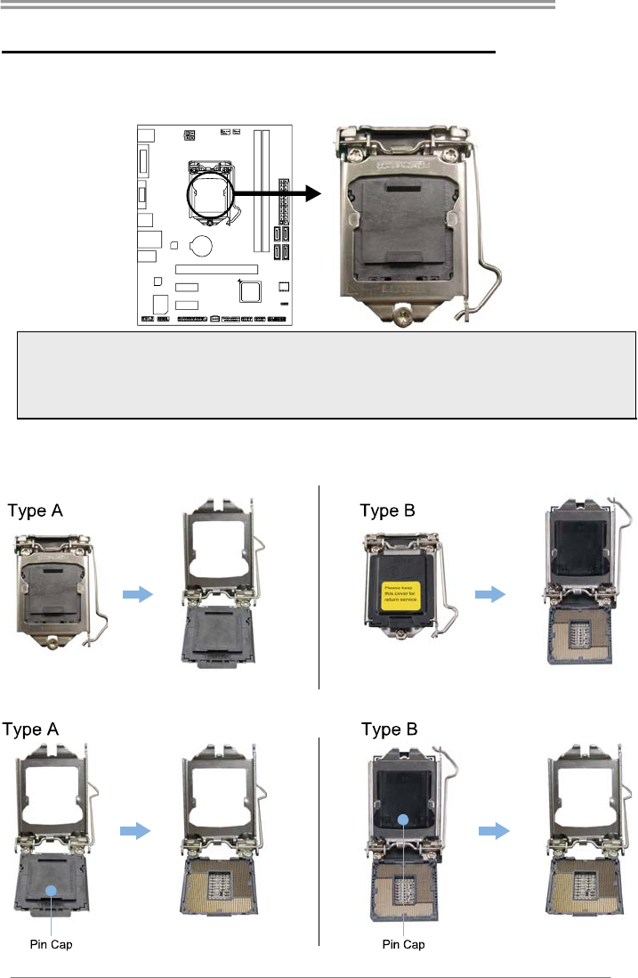
2.1 Install Central Processing Unit (CPU)
Step 1: Locate the CPU socket on the motherboard
Note1: Remove Pin Cap before installation, and make good preservation for future use. When
the CPU is removed, cover the Pin Cap on the empty socket to ensure pin legs won’t be
damaged.
Note2: The motherboard might equip with two different types of pin cap. Please refer below
instruction to remove the pin cap.
Step 2: Pull the socket locking lever out from the socket and then raise the lever
up.
Step 3: Remove the Pin Cap.
Motherboard Manual
6
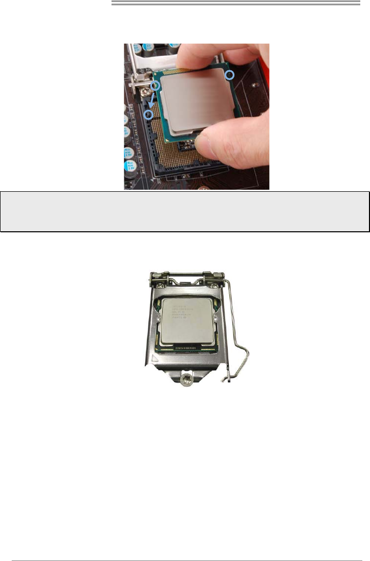
Step 4: Hold processor with your thumb and index fingers, oriented as shown.
Align the notches with the socket. Lower the processor straight down
without tilting or sliding the processor in the socket.
Note1: The LGA1155 CPU is not compatible with LGA 1150 socket. Do not install a LGA 1155 CPU
on the LGA 1150 socket.
Note2: The CPU fits only in one correct orientation. Do not force the CPU into the socket to prevent
damaging the CPU.
Step 5: Hold the CPU down firmly, and then lower the lever to locked position to
complete the installation.
B85MG
7
2.2 Install a Heatsink
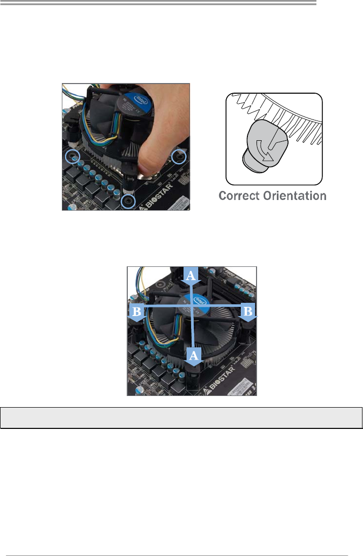
Step 1: Place the CPU fan assembly on top of the installed CPU and make sure
that the four fasteners match the motherboard holes. Orient the assembly
and make the fan cable is closest to the CPU fan connector.
Ensure the fastener slots are pointing perpendicular to the heatsink.
Step 2: Press down two fasteners at one time in a diagonal sequence to secure
the CPU fan assembly in place. As each fastener locks into position a click
should be heard.
Note1: Do not forget to connect the CPU fan connector.
Note2: For proper installation, please kindly refer to the installation manual of your CPU heatsink.
Motherboard Manual
8
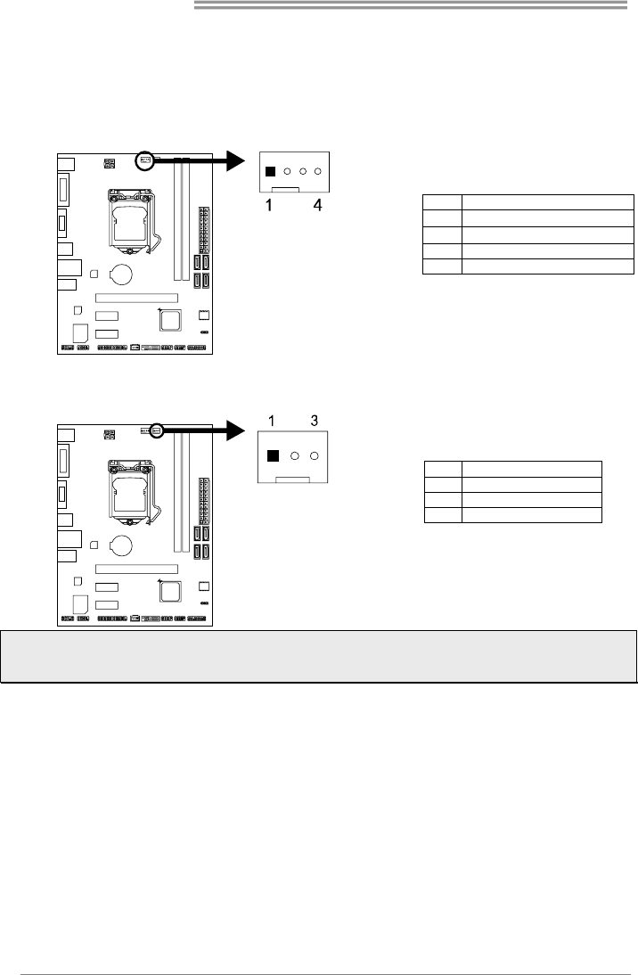
2.3 Connect Cooling Fans
These fan headers support cooling-fans built in the computer. The fan cable and
connector may be different according to the fan manufacturer.
CPU_FAN1: CPU Fan Header
Pin Assignment
1 Ground
2 +12V
3 FAN RPM rate sense
4 Smart Fan Control (By Fan)
SYS_FAN1: System Fan Header
Pin Assignment
1 Ground
2 +12V
3 FAN RPM rate sense
Note: CPU_FAN1, SYS_FAN1 support 4-pin and 3-pin head connectors. When connecting with
wires onto connectors, please note that the red wire is the positive and should be connected to
pin#2, and the black wire is Ground and should be connected to pin#1(GND).
B85MG
9
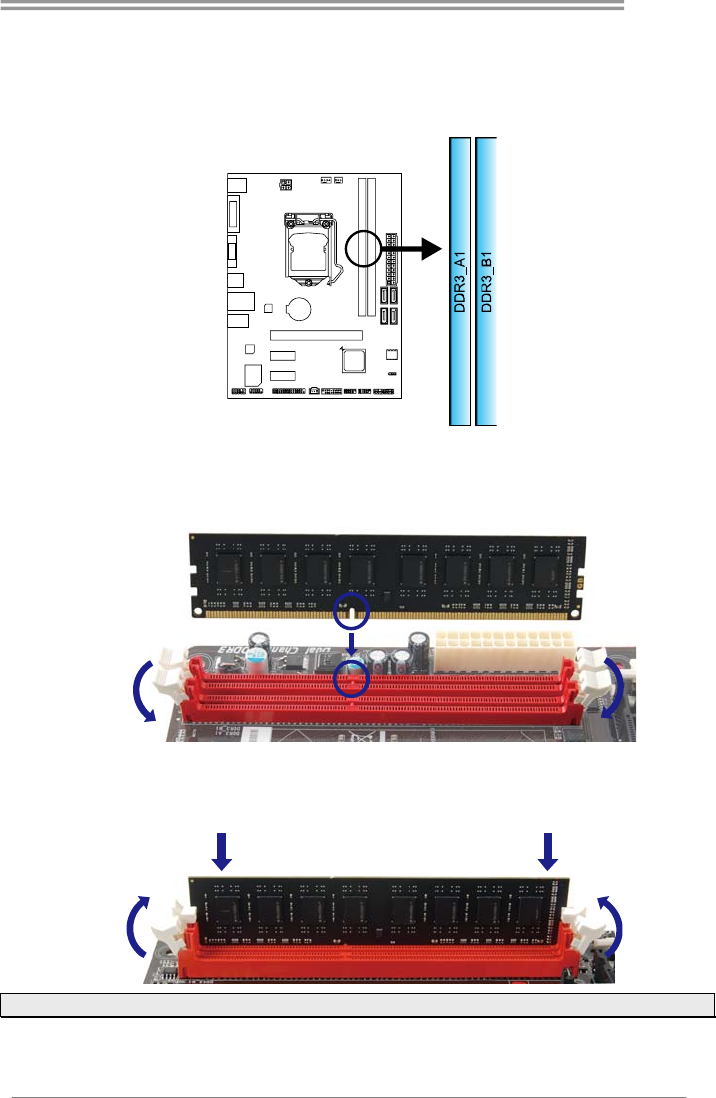
2.4 Install System Memory
DDR3 Modules
Step 1: Unlock a DIMM slot by pressing the retaining clips outward. Align a DIMM
on the slot such that the notch on the DIMM matches the break on the slot.
Step 2: Insert the DIMM vertically and firmly into the slot until the retaining clips
snap back in place and the DIMM is properly seated.
Note: If the DIMM does not go in smoothly, do not force it. Pull it all the way out and try again.
Motherboard Manual
10
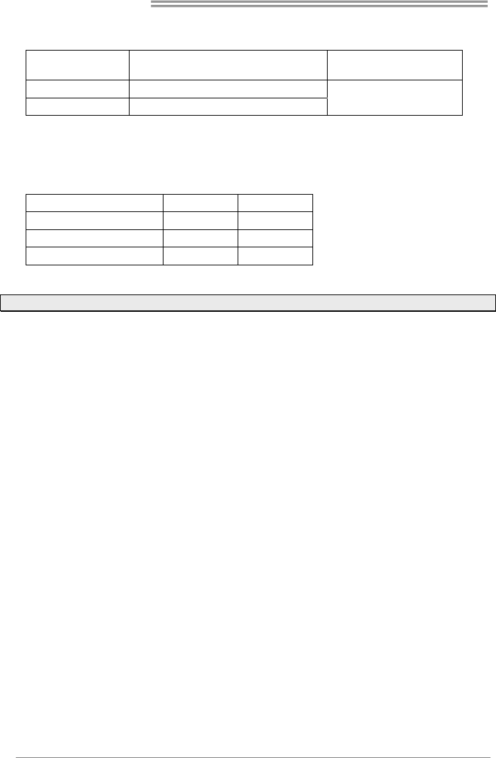
Memory Capacity
DIMM Socket
Location DDR3 Module Total Memory Size
DDR3_A1 512MB/1GB/2GB/4GB/8GB
DDR3_B1 512MB/1GB/2GB/4GB/8GB Max is 16GB.
Dual Channel Memory Installation
Please refer to the following requirements to activate Dual Channel function:
Install memory module of the same density in pairs, shown in the table.
Dual Channel Status DDR3_A1 DDR3_B1
Disabled O X
Disabled X O
Enabled O O
(O means memory installed, X means memory not installed.)
Note: The DRAM bus width of the memory module must be the same (x8 or x16)
2.5 Expansion Slots
Install an Expansion Card
You can install your expansion card by following steps:
1. Read the related expansion card's instruction document before install the
expansion card into the computer.
2. Remove your computer's chassis cover, screws and slot bracket from the
computer.
3. Place a card in the expansion slot and press down on the card until it is
completely seated in the slot.
4. Secure the card’s metal bracket to the chassis back panel with a screw.
5. Replace your computer's chassis cover.
6. Power on the computer, if necessary, change BIOS settings for the
expansion card.
7. Install related driver for the expansion card.
B85MG
11
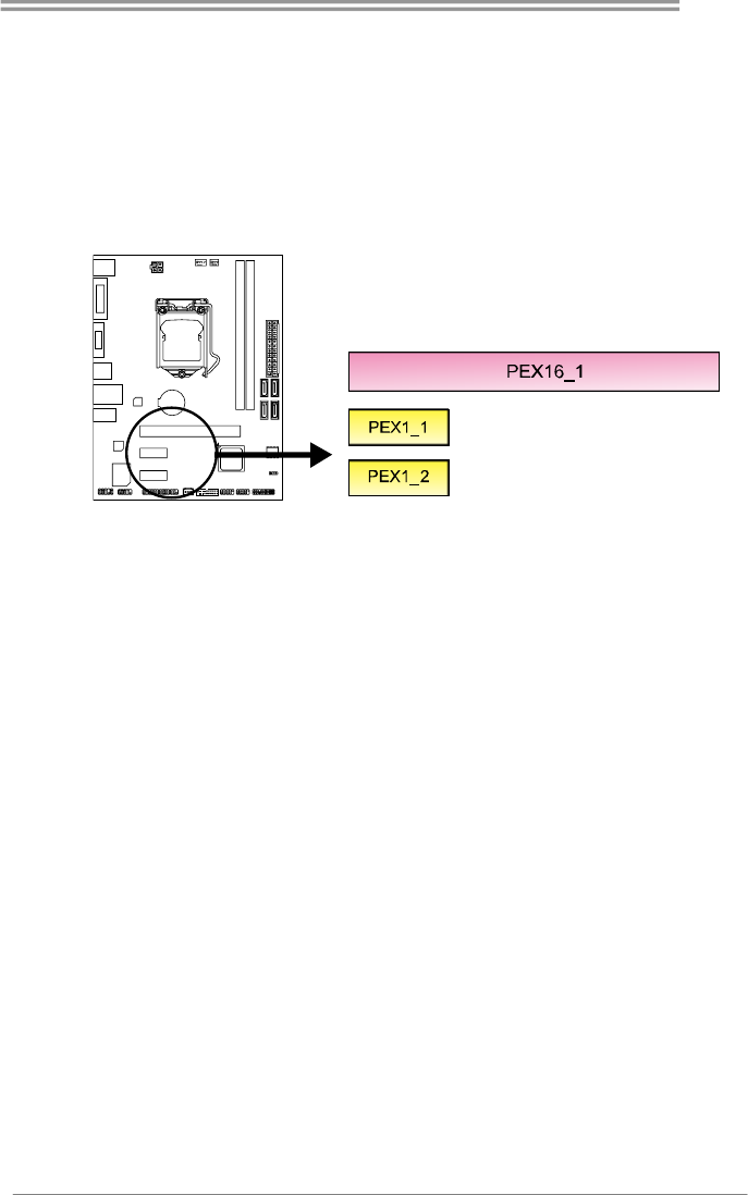
PEX16_1: PCI-Express Gen3 x16 Slot
- PCI-Express 3.0 compliant.
- Maximum theoretical realized bandwidth of 16GB/s simultaneously per
direction, for an aggregate of 32GB/s totally.
PEX1_1/1_2: PCI-Express Gen2 x1 Slots
- PCI-Express 2.0 compliant.
- Data transfer bandwidth up to 500MB/s per direction; 1GB/s in total
Motherboard Manual
12
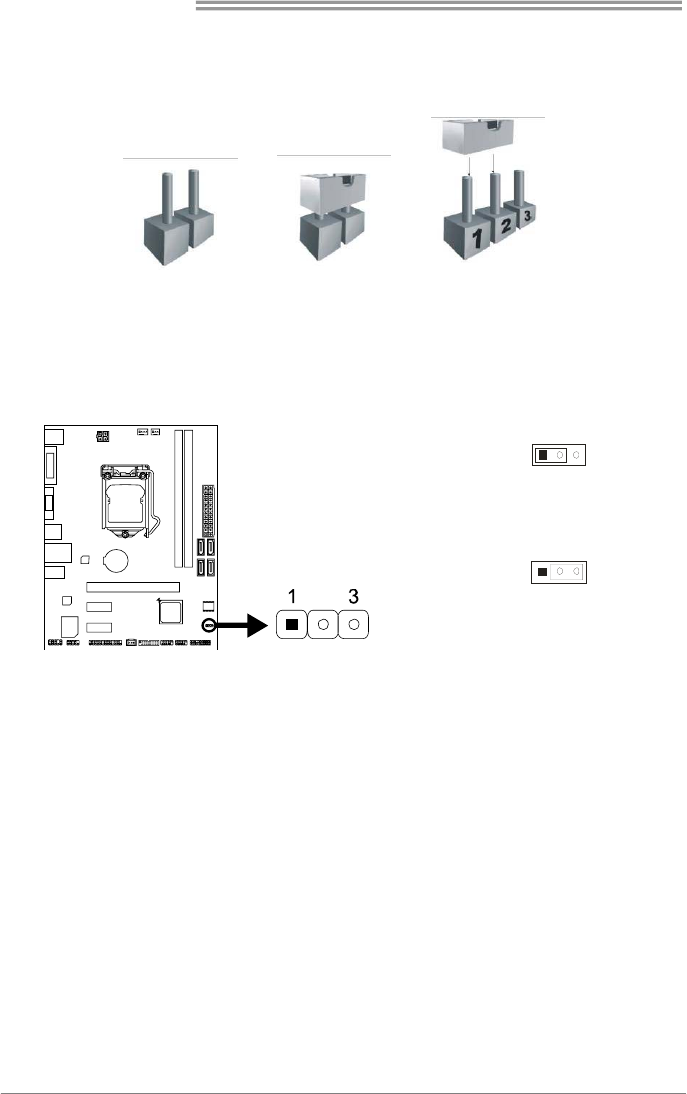
2.6 Jumper Setting
The illustration shows how to set up jumpers. When the jumper cap is placed on
pins, the jumper is “close”, if not, that means the jumper is “open”.
Pin opened Pin closed Pin1-2 closed
JCMOS1: Clear CMOS Jumper
Placing the jumper on pin2-3, it allows user to restore the BIOS safe setting and
the CMOS data. Please carefully follow the procedures to avoid damaging the
motherboard.
31
Pin 1-2 Close:
Normal Operation (default).
31
Pin 2-3 Close:
Clear CMOS data.
※ Clear CMOS Procedures:
1. Remove AC power line.
2. Set the jumper to “Pin 2-3 close”.
3. Wait for five seconds.
4. Set the jumper to “Pin 1-2 close”.
5. Power on the AC.
6. Load Optimal Defaults and save settings in CMOS.
B85MG
13
2.7 Headers & Connectors
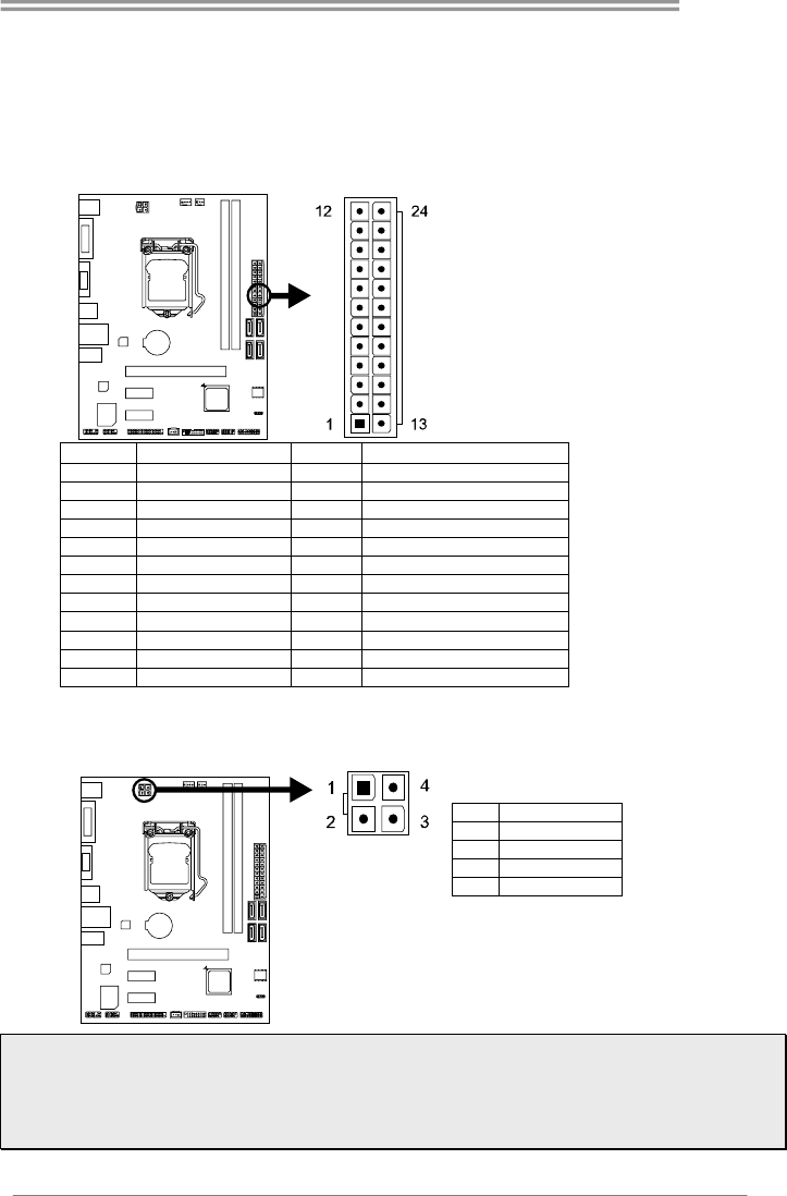
ATXPWR1: ATX Power Source Connector
For better compatibility, we recommend to use a standard ATX 24-pin power
supply for this connector. Make sure to find the correct orientation before plugging
the connector.
Pin Assignment Pin Assignment
13 +3.3V 1 +3.3V
14 -12V 2 +3.3V
15 Ground 3 Ground
16 PS_ON 4 +5V
17 Ground 5 Ground
18 Ground 6 +5V
19 Ground 7 Ground
20 NC 8 PW_OK
21 +5V 9 Standby Voltage+5V
22 +5V 10 +12V
23 +5V 11 +12V
24 Ground 12 +3.3V
ATXPWR2: ATX Power Source Connector
The connector provides +12V to the CPU power circuit.
Pin Assignment
1 +12V
2 +12V
3 Ground
4 Ground
Note1: Before you power on the system, please make sure that both ATXPWR1 and ATXPWR2
connectors have been plugged-in.
Note2: Insufficient power supplied to the system may result in instability or the peripherals not
functioning properly. Use of a PSU with a higher power output is recommended when configuring a
system with more power-consuming devices.
Motherboard Manual
14
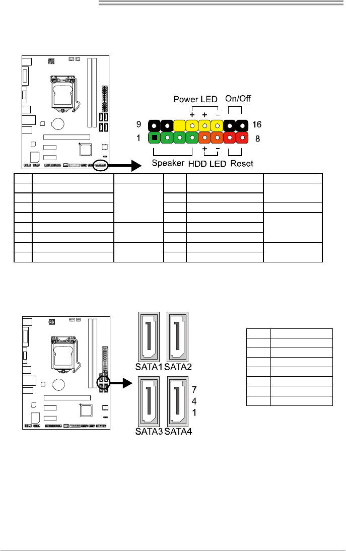
PANEL1: Front Panel Header
This 16-pin header includes Power-on, Reset, HDD LED, Power LED, and speaker
connection. It allows user to connect the PC case’s front panel switch functions.
Pin Assignment Function Pin Assignment Function
1 +5V 9 N/A
2 N/A 10 N/A N/A
3 N/A 11 N/A N/A
4 Speaker
Speaker
Connector
12 Power LED (+)
5 HDD LED (+) 13 Power LED (+)
6 HDD LED (-)
Hard drive
LED 14 Power LED (-)
Power LED
7 Ground 15 Power button
8 Reset control Reset button 16 Ground Power-on button
SATA1~SATA4: Serial ATA 3.0 Connectors
These connectors connect to SATA hard disk drives via SATA cables. It satisfies
the SATA 3.0 specification and with transfer rate of 6.0Gb/s.
Pin Assignment
1 Ground
2 TX+
3 TX-
4 Ground
5 RX-
6 RX+
7 Ground
B85MG
15
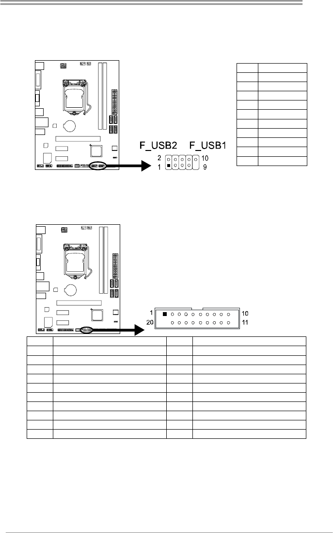
F_USB1/2: Header for USB 2.0 Ports at Front Panel
This header allows user to add additional USB ports on the PC front panel, and
also can be connected with a wide range of external peripherals.
Pin Assignment
1 +5V (fused)
2 +5V (fused)
3 USB-
4 USB-
5 USB+
6 USB+
7 Ground
8 Ground
9 NC
10 Key
JFRONT_USB3_1: Header for USB 3.0 Ports at Front Panel
This header allows user to add additional USB ports on the PC front panel, and
also can be connected with a wide range of external peripherals.
Pin Assignment Pin Assignment
1 VBUS0 11 D2+
2 SSRX1- 12 D2-
3 SSRX1+ 13 Ground
4 Ground 14 SSTX2+
5 SSTX1- 15 SSTX2-
6 SSTX1+ 16 Ground
7 Ground 17 SSRX2+
8 D1- 18 SSRX2-
9 D1+ 19 VBUS1
10 ID 20 Key
Motherboard Manual
16
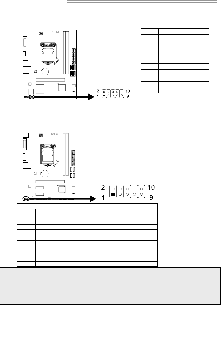
J_COM: Serial Port Header
The motherboard has a serial port header for connecting RS-232 Port.
Pin Assignment
1 Carrier detect
2 Received data
3 Transmitted data
4 Data terminal ready
5 Signal ground
6 Data set ready
7 Request to send
8 Clear to send
9 Ring indicator
10 NC
F_AUDIO1: Front Panel Audio Header
This header allows user to connect the chassis-mount front panel audio I/O which
supports HD and AC’97 audio standards.
HD Audio AC’97
Pin Assignment Pin Assignment
1 Mic Left in 1 Mic In
2 Ground 2 Ground
3 Mic Right in 3 Mic Power
4 GPIO 4 Audio Power
5 Right line in 5 RT Line Out
6 Jack Sense 6 RT Line Out
7 Front Sense 7 Reserved
8 Key 8 Key
9 Left line in 9 LFT Line Out
10 Jack Sense 10 LFT Line Out
Note1: It is recommended that you connect a high-definition front panel audio module to this
connector to avail of the motherboard's high definition audio capability.
Note2: Please try to disable the "Front Panel Jack Detection" if you want to use an AC'97 front
audio output cable. The function can be found via O.S. Audio Utility.
Note3: To configure 7.1-channel audio, you have to use a chassis with HD front panel audio
module and enable the multi-channel audio feature through O.S. Audio Utility.
B85MG
17
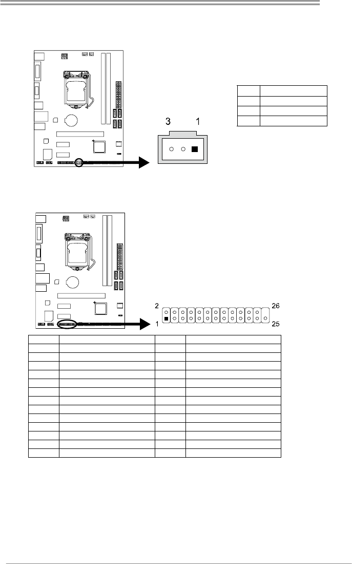
JSPDIFOUT1: Digital Audio-out Connector
The connector is for connecting the S/PDIF output bracket.
Pin Assignment
1 +5V
2 SPDIF_OUT
3 Ground
J_PRINT1: Printer Port Header
This header allows user to connect a printer to the PC.
Pin Assignment Pin Assignment
1 -Strobe 14 Ground
2 -ALF 15 Data 6
3 Data 0 16 Ground
4 -Error 17 Data 7
5 Data 1 18 Ground
6 -Init 19 -ACK
7 Data 2 20 Ground
8 -Scltin 21 Busy
9 Data 3 22 Ground
10 Ground 23 PE
11 Data 4 24 Ground
12 Ground 25 SCLT
13 Data 5 26 Key

Motherboard Manual
18
CHAPTER 3: UEFI BIOS & SOFTWARE
3.1 UEFI BIOS Setup
z The BIOS Setup program can be used to view and change the BIOS
settings for the computer. The BIOS Setup program is accessed by pressing
the <DEL> key after the Power-On Self-Test (POST) memory test begins
and before the operating system boot begins.
z For further information of setting up the UEFI BIOS, please refer to the UEFI
BIOS Manual in the Setup DVD.
3.2 BIOS Update
The BIOS can be updated using either of the following utilities:
z BIOSTAR BIOS Flasher: Using this utility, the BIOS can be updated from a
file on a hard disk, a USB drive (a flash drive or a USB hard drive), or a
CD-ROM.
z BIOSTAR BIOS Update Utility: It enables automated updating while in the
Windows environment. Using this utility, the BIOS can be updated from a file
on a hard disk, a USB drive (a flash drive or a USB hard drive), or a
CD-ROM, or from the file location on the Web.
BIOSTAR BIOS Flasher
BIOSTAR BIOS Flasher is a BIOS flashing utility providing you an easy and simple
way to update your BIOS via USB pen drive.
Note1: This utility only allows storage device with FAT32/16 format and single partition.
Note2: Shutting down or resetting the system while updating the BIOS will lead to system boot
failure.
Updating BIOS with BIOSTAR BIOS Flasher
1. Go to the website to download the latest BIOS file for the motherboard.
2. Then, copy and save the BIOS file into a USB flash (pen) drive.
3. Insert the USB pen drive that contains the BIOS file to the USB port.
4. Power on or reset the computer and then press <F12> during the POST process.
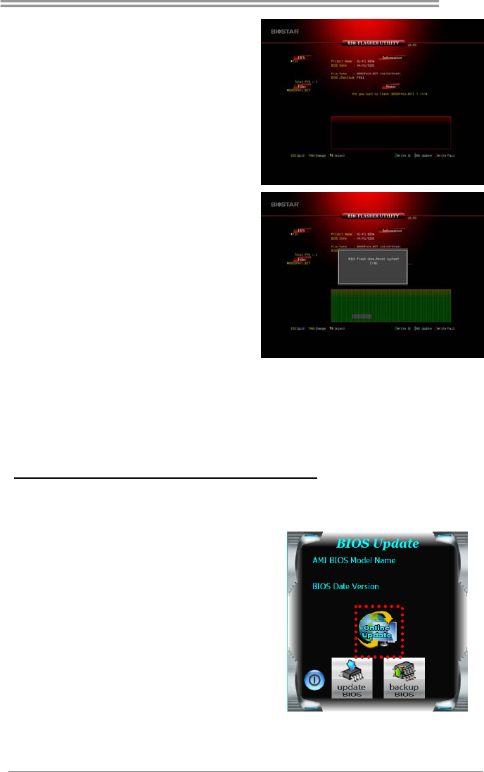
5. After entering the POST screen,
the BIOS-FLASHER utility pops
out. Choose [fs0] to search for the
BIOS file.
B85MG
19
6. Select the proper BIOS file, and a
message asking if you are sure to
flash the BIOS file. Click Yes to
start updating BIOS.
7. A dialog pops out after BIOS flash
is completed, asking you to restart
the system. Press the [Y] key to
restart system.
8. While the system boots up and the full screen logo shows up, press <DEL> key to
enter BIOS setup.
After entering the BIOS setup, please go to the Save & Exit, using the Restore
Defaults function to load Optimized Defaults, and select Save Changes and
Reset to restart the computer. Then, the BIOS Update is completed.
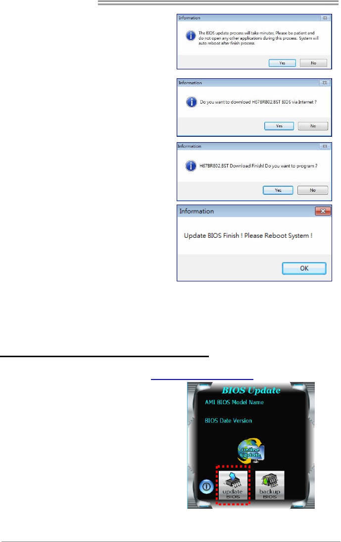
BIOS Update Utility (through the Internet)
1. Installing BIOS Update Utility from the DVD Driver.
2. Please make sure the system is connected to the internet before using this
function.
3. Launch BIOS Update Utility and
click the Online Update button on
the main screen.
Motherboard Manual
20
4. An open dialog will show up to
request your agreement to start the
BIOS update. Click Yes to start the
online update procedure.
5. If there is a new BIOS version, the
utility will ask you to download it.
Click Yes to proceed.
6. After the download is completed,
you will be asked to program
(update) the BIOS or not. Click Yes
to proceed.
7. After the updating process is
finished, you will be asked you to
reboot the system. Click OK to
reboot.
8. While the system boots up and the full screen logo shows up, press <DEL> key
to enter BIOS setup.
After entering the BIOS setup, please go to the Save & Exit, using the Restore
Defaults function to load Optimized Defaults, and select Save Changes and
Reset to restart the computer. Then, the BIOS Update is completed.
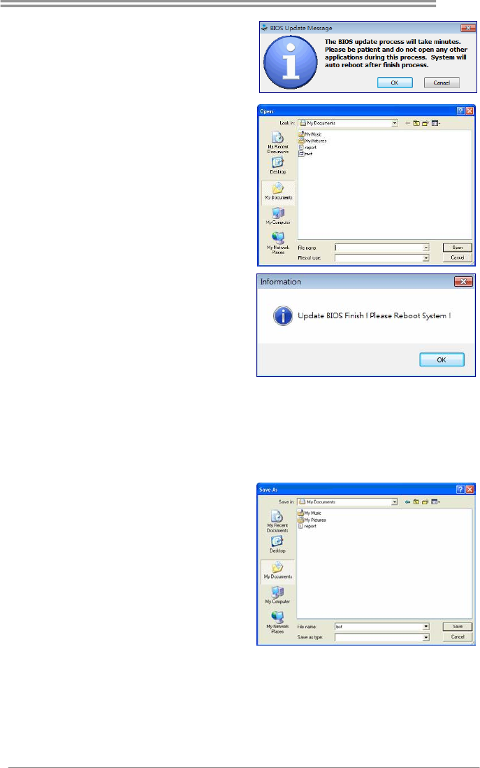
BIOS Update Utility (through a BIOS file)
1. Installing BIOS Update Utility from the DVD Driver.
2. Download the proper BIOS from http://www.biostar.com.tw/
3. Launch BIOS Update Utility and
click the Update BIOS button on
the main screen.
B85MG
21
4. A warning message will show up
to request your agreement to start
the BIOS update. Click OK to start
the update procedure.
5. Choose the location for your BIOS
file in the system. Please select
the proper BIOS file, and then
click on Open. It will take several
minutes, please be patient.
6. After the BIOS Update process is
finished, click on OK to reboot the
system.
7. While the system boots up and the full screen logo shows up, press <DEL> key
to enter BIOS setup.
After entering the BIOS setup, please go to the Save & Exit, using the Restore
Defaults function to load Optimized Defaults, and select Save Changes and
Reset to restart the computer. Then, the BIOS Update is completed.
Backup BIOS
Click the Backup BIOS button on
the main screen for the backup of
BIOS, and select a proper location
for your backup BIOS file in the
system, and click Save.
Motherboard Manual
22
3.3 Software
Installing Software
1. Insert the Setup DVD to the optical drive. The driver installation program would
appear if the Auto-run function has been enabled.
2. Select Software Installation, and then click on the respective software title.
3. Follow the on-screen instructions to complete the installation.
Launching Software
After the installation process is completed, you will see the software icon showing on
the desktop. Double-click the icon to launch it.
Note1: All the information and content about following software are subject to be changed without
notice. For better performance, the software is being continuously updated.
Note2: The information and pictures described below are for your reference only. The actual
information and settings on board may be slightly different from this manual.
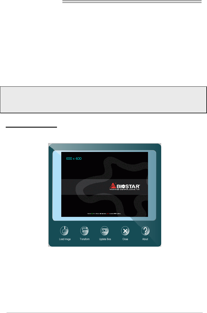
BIOScreen Utility
This utility allows you to personalize your boot logo easily. You can choose BMP as
your boot logo so as to customize your computer.
Please follow the step-by-step instructions below to update boot logo:
z Load Image:Choose the picture as the boot logo.
z Transform:Transform the picture for BIOS and preview the result.
z Update Bios:Write the picture to BIOS Memory to complete the update.
B85MG
23
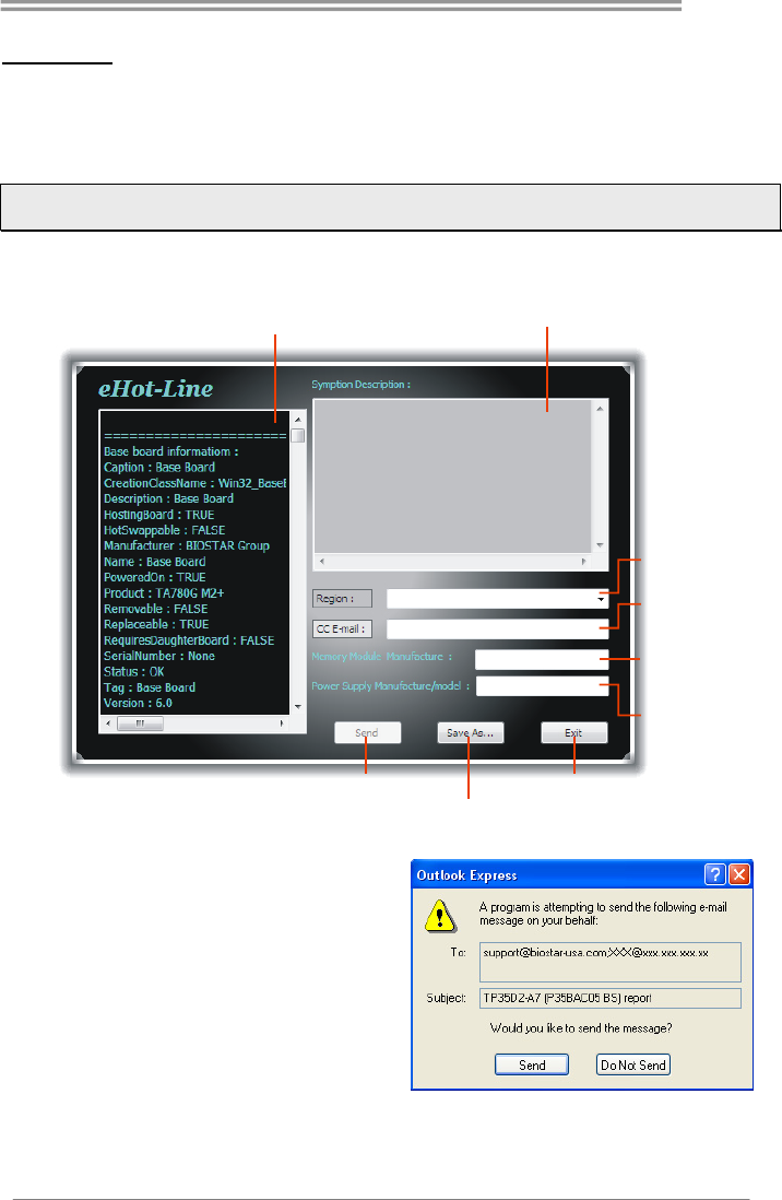
eHot-Line
eHot-Line is a convenient utility that helps you to contact with our Tech-Support system.
This utility will collect the system information which is useful for analyzing the problem you
may have encountered, and then send these information to our tech-support department
to help you fix the problem.
Note: Before you use this utility, please set Outlook Express as your default e-mail client
application program.
This block will show
the information which
would be collected in
the mail.
Provide the e-mail
address that you would
like to send the copy to.
Provide the name of
the power supply
manufacturer and the
model no.
Send the mail out.
Save these information to a .txt file
Exit this dialog.
Select your area or
the area close to you.
*
Provide the name of
the memory module
manufacturer.
*
Describe condition
of your system.
*
*
represents important
information that you
must provide. Without
this information, you may
not be able to send out
the mail.
After filling up this information, click
“Send” to send the mail out. A
warning dialog would appear asking
for your confirmation; click “Send” to
confirm or “Do Not Send” to cancel.
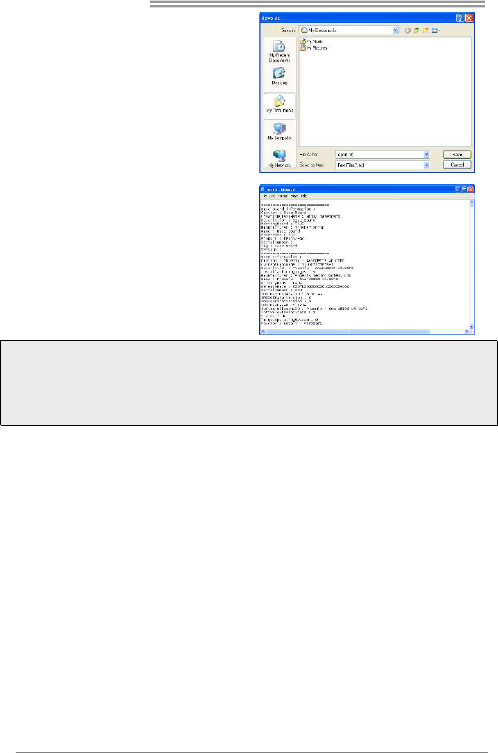
If you want to save this information to
a .txt file, click “Save As…” and then
you will see a saving dialog appears
asking you to enter file name.
Motherboard Manual
24
Enter the file name and then click
“Save”. Your system information will be
saved to a .txt file.
Open the saved .txt file, you will see
your system information including
motherboard/BIOS/CPU/video/
device/OS information. This
information is also concluded in the
sent mail.
Note1: We will not share customer’s data with any other third parties, so please feel free to provide
your system information while using eHot-Line service.
Note2: If you are not using Outlook Express as your default e-mail client application, you may need
to save the system information to a .txt file and send the file to our tech support with other e-mail
application. Go to the following website http://www.biostar.com.tw/app/en/about/contact.php for
getting our contact information.
B85MG
25
Smart Connect Technology
Intel® Smart Connect Technology is designed to update programs by periodically
waking your computer from sleep/standby mode for a short time. This function works
with applications that automatically get their data from the Internet.
System Requirement:
z Intel Smart Connect Technology enabled in BIOS Setup
z Set the “ACPI Sleep State” to S3 in BIOS Setup.
z Windows 7 and Windows 8
z Normal internet connection
Configuring Intel Smart Connect Technology
Step 1: After installing the operating system and motherboard drivers, install the Intel
Smart Connect Technology application. Restart your computer when completed.
Step 2: Click on start menu and input "regedit" in the search bar. Press enter to open
the registry editor. Look for the following directory in the registry editor:
Computer\HKEY_LOCAL_MACHINE\SOFTWARE\Intel\Intel Smart Connect Technology
Right-click on Intel Smart Connect Technology and select New > Key. Type “OEM”.
Note: Intel Smart Connect Technology is for S3 mode only. During the updating process, the
monitor will not light up and no sound will be output from the speaker.
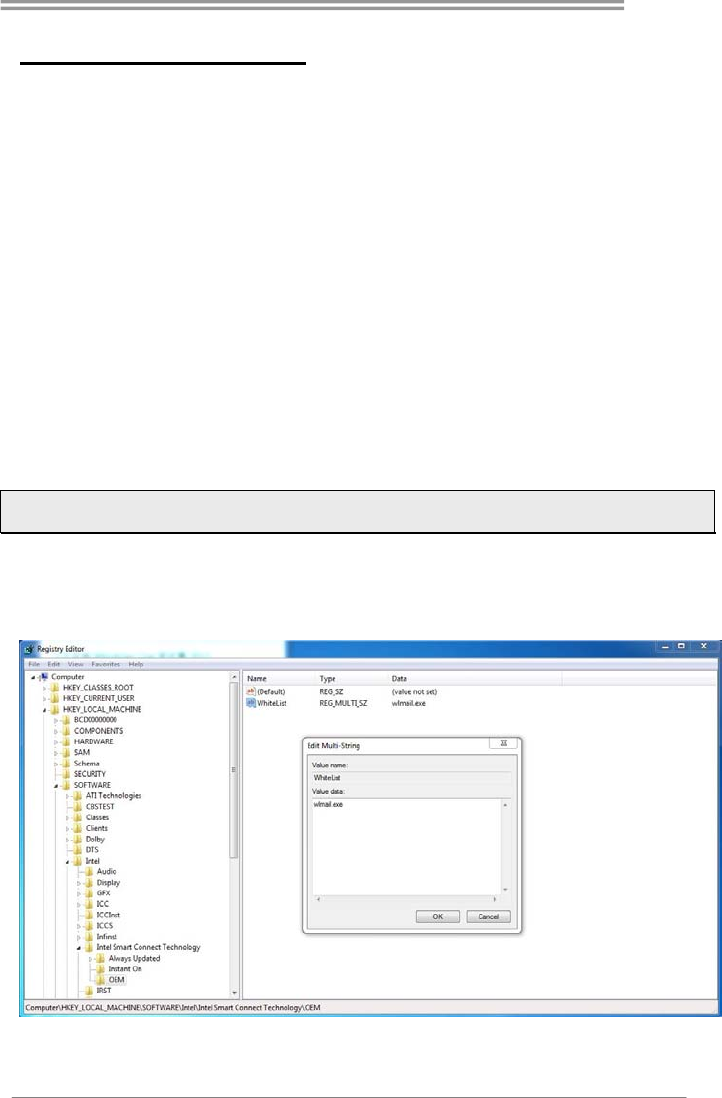
Step 3: As shown in the screenshot below, right-click on OEM, select New >
Multi-String Value, and type “WhiteList”. Double-click WhiteList and type the
application name to be added in Edit Multi-String. For example, to add Microsoft Live
Mail, type “wlmail.exe”. Restart your computer when completed.
Step 4: After completing the steps above, go to Start\All Programs\Intel and launch
Intel(R) Smart Connect Technology.
Motherboard Manual
26
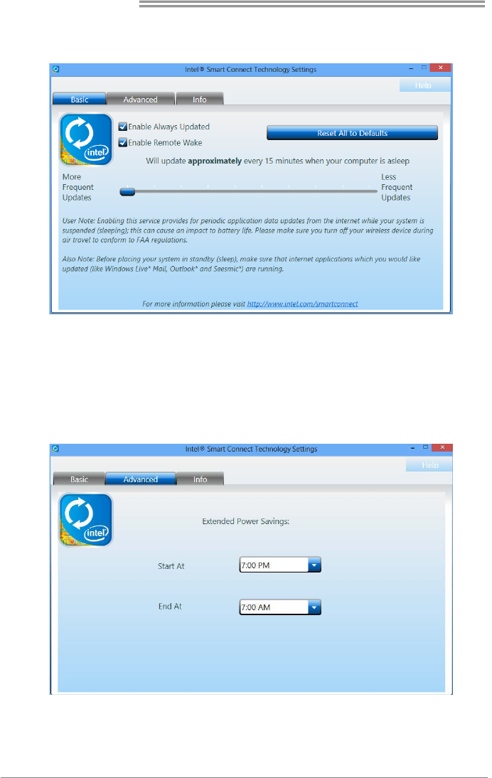
Basic and advanced settings
Basic Tab
Update Frequency slider: This slider bar sets the amount of time the feature waits to wake
your computer and update your applications. Move the slider in the user interface to change
the frequency. The slider bar can be set to wake and update your computer from every 15 to
60 minutes. The longer the time between updates the less power the feature consumes.
Reset All to Defaults button: This button is designed to reset Intel® Smart Connect
Technology back to the original factory setting for wake frequency.
Advanced Tab
Extended Power Savings: You can set a time for Intel Smart Connect Technology to work in
Extended Power Savings mode. This night time mode updates your computer every two
hours, saving power for the times you are not using your computer.
B85MG
27
Rapid Start Technology
Intel® Rapid Start technology enables your system to get up and running faster from
even the deepest sleep, saving time and power consumption. Feel secure knowing that
your system will still resume to working conditions in the event of unexpected power
loss while in sleep mode.
System Requirement:
z An Intel® SATA SSD (SATA Gen2 or Gen3. Preferably Gen3, and 80 GB or
larger)
z Windows 7 and Windows 8
Note1: Please visit below webpage for more details about operating systems supporting
http://www.intel.com/p/en_US/support
Installing Intel® RST:
Step 1: BIOS Setting
1-1 Go to [Advanced Menu] > [ACPI Settings], and set [ACPI Sleep State] to S3
(Suspend to RAM)
1-2 Go to [Advanced Menu] > [SATA Configuration], and set [SATA Mode
Selection] to AHCI
1-3 Go to [Advanced Menu] and set [Intel(R) Rapid Start Technology] to Enabled
1-4 Save your changes, and then exit the BIOS Setup.
Step 2: Operating System Installation
Step 3: Installing Intel® Rapid Start Application
3-1 Insert the setup Driver DVD into your optical drive. Click “Intel Rapid Start
Technology” to launch the program.
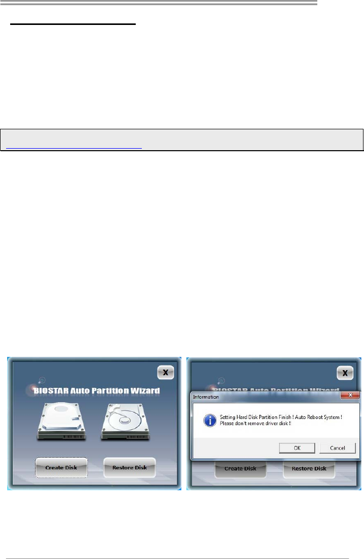
3-2 Below window will pop-out, then click “Create Disk” to star disk partition. After
disk partition finished, please click “OK” then system will reboot automatically.
Motherboard Manual
28
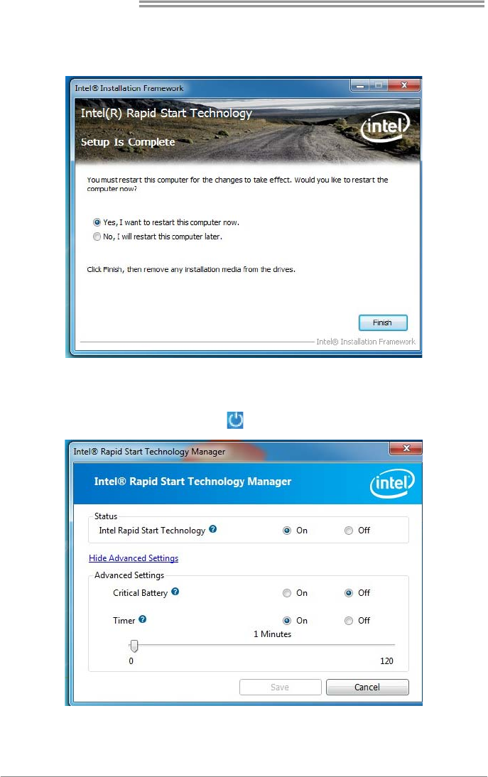
3-3 After rebooting, the system will setup Intel® Rapid Start Technology
automatically. We recommend you restart the system after this installation is
complete,
Step 4: Configuring Intel® Rapid Start Application
Launch the Intel® Rapid Start Technology Manager application from [Start] > [All
Programs] > [Intel] or click the icon in the notification area.

B85MG
29
Intel® Small Business Advantage
Intel Small Business Advantage (Intel SBA) provides an out-of-the-box hardware-based
security and productivity suite designed for the small business user.
Software Monitor
Software Monitor helps keep critical security software running by monitoring it at the
hardware level and alerting the business if there has been an attack. The Software
Monitor also maintains an event log that shows status information and any errors
generated, so businesses can know what happened.
Data Backup and Restore
Data Backup and Restore provides reliable after-hours backup of critical data using the
local maintenance timer to power on the computer. Data can be backed up to a
designated location.
USB Blocker
The optional USB Blocker lets businesses control access to their infrastructure,
preventing unauthorized USB devices or file imports or exports on company computers.
PC Health Center
PC Health Center can schedule and do PC maintenance tasks after hours, without
interrupting employee work time. Tasks such as updating the operating system,
deleting temporary internet files, and running disk defragmentation can be done at night.
PC Health Center works even if the computer is powered-down, as long as it is plugged
in.
Energy Saver
With the optional Energy Saver, businesses can save energy by scheduling PCs to
power-down at the end of the day and turn on before the work day begins - ready for
employees as they arrive in the morning.
Supported Operating Systems:
Windows 7 and Windows 8
Note1: Please visit below webpage for more details about operating systems supporting
http://www.intel.com/p/en_US/support
Motherboard Manual
30
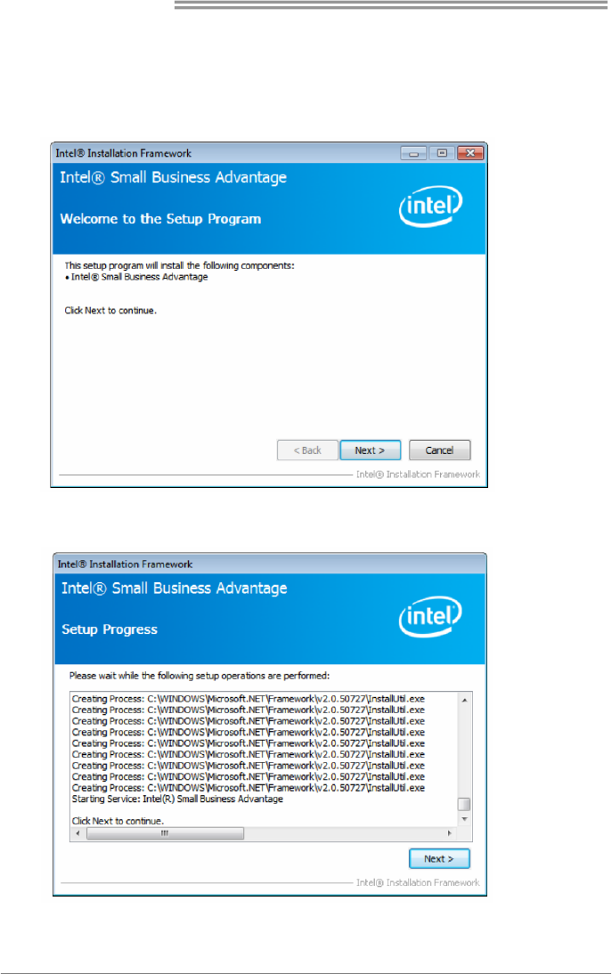
Installing Intel SBA
This procedure describes how to install Intel SBA.
1. Logon to the computer with a user that has administrator privileges.
2. Copy the Setup.exe file to the computer.
3. Double-click Setup.exe.
The Welcome to the Setup Program window opens.
4. Click Next. The installer starts the installation and the Setup Progress window
opens showing the progress of the installation. When installation is complete, the
installer starts the Intel SBA service and the Next button is enabled.
5. Click Next. The Setup Is Complete window opens.
6. Click Finish. The installer closes.
B85MG
31
CHAPTER 4: USEFUL HELP
4.1 Driver Installation
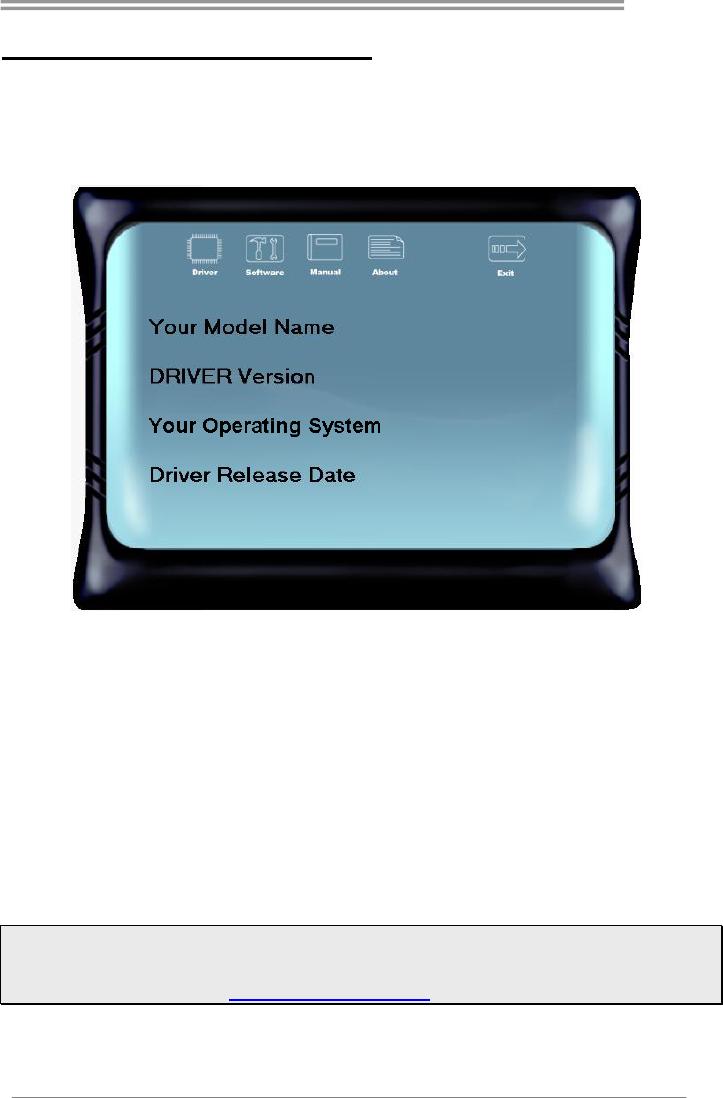
After you installed your operating system, please insert the Fully Setup Driver
DVD into your optical drive and install the driver for better system performance.
You will see the following window after you insert the DVD
The setup guide will auto detect your motherboard and operating system.
A. Driver Installation
To install the driver, please click on the Driver icon. The setup guide will list the
compatible driver for your motherboard and operating system. Click on each
device driver to launch the installation program.
B. Software Installation
To install the software, please click on the Software icon. The setup guide will list
the software available for your system, click on each software title to launch the
installation program.
C. Manual
Aside from the paperback manual, we also provide manual in the Driver DVD.
Click on the Manual icon to browse for available manuals.
Note1: If this window didn’t show up after you insert the Driver DVD, please use file browser to
locate and execute the file SETUP.EXE under your optical drive.
Note2: You will need Acrobat Reader to open the manual file. Please download the latest version of
Acrobat Reader software from http://get.adobe.com/reader/

Motherboard Manual
32
4.2 AMI BIOS Beep Code
Boot Block Beep Codes
Number of Beeps Description
Continuing Memory sizing error or Memory module not found
POST BIOS Beep Codes
Number of Beeps Description
1 Success booting.
8 Display memory error (system video adapter)
4.3 Troubleshooting
Probable Solution
1. There is no power in the system. Power
LED does not shine; the fan of the
power supply does not work
2. Indicator light on keyboard does not
shine.
1. Make sure power cable is securely
plugged in.
2. Replace cable.
3. Contact technical support.
System is inoperative. Keyboard lights are
on, power indicator lights are lit, and hard
drives are running.
Using even pressure on both ends of the
DIMM, press down firmly until the module
snaps into place.
System does not boot from a hard disk drive,
but can be booted from optical drive.
1. Check cable running from disk to disk
controller board. Make sure both ends
are securely plugged in; check the
drive type in the standard CMOS
setup.
2. Backing up the hard drive is
extremely important. All hard disks
are capable of breaking down at any
time.
System only boots from an optical drive.
Hard disks can be read, applications can be
used, but system fails to boot from a hard
disk.
1. Back up data and applications files.
2. Reformat the hard drive. Re-install
applications and data using backup
disks.
Screen message shows “Invalid
Configuration” or “CMOS Failure.”
Review system’s equipment. Make sure
correct information is in setup.
System cannot boot after user installs a
second hard drive.
1. Set master/slave jumpers correctly.
2. Run SETUP program and select
correct drive types. Call the drive
manufacturers for compatibility with
other drives.

B85MG
33
CPU Overheated
If the system shutdown automatically after power on system for seconds, that
means the CPU protection function has been activated.
When the CPU is over heated, the motherboard will shutdown automatically to
avoid a damage of the CPU, and the system may not power on again.
In this case, please double check:
1. The CPU cooler surface is placed evenly with the CPU surface.
2. CPU fan is rotated normally.
3. CPU fan speed is fulfilling with the CPU speed.
After confirmed, please follow steps below to relief the CPU protection function.
1. Remove the power cord from power supply for seconds.
2. Wait for seconds.
3. Plug in the power cord and boot up the system.
Or you can:
1. Clear the CMOS data.
2. Wait for seconds.
3. Power on the system again.

Motherboard Manual
34
APPENDIX: Specifications in Other Languages
Arabic
تﺎﻔﺻاﻮﻤﻟا
ﺔﺠﻟﺎﻌﻤﻟا ةﺪﺣو ةﺪﻋﺎﻗ
ﺔﻳﺰآﺮﻤﻟا
ﺬﺧﺄﻤﻟا1150 ىد مإ ﻪﻳا ﺞﻟﺎﻌﻤﻟ Intel® Core i7 / i5 / i3 / Pentium / Celeron
ﺞﻟﺎﻌﻤﻟا ﻢﻴﻤﺼﺗ ﻲﻓ ﺔﻳراﺮﺤﻟا ﺔﻗﺎﻄﻠﻟ ﻰﺼﻗﻷا ﺪﺤﻟا )TDP – thermal design power :( 95طاو .
*ﻊﻗﻮﻤﻟا ﻰﻟإ عﻮﺟﺮﻟا ﻰﺟﺮﻳwww.biostar.com.tw ﺔﻤﺋﺎﻘﻟ ﺞﻟﺎﻌﻤﻟا ﻢﻋد CPU.
ﺢﺋاﺮﺸﻟا ﺔﻋﻮﻤﺠﻣ IINTEL® B85
ةﺮآاﺬﻟا
يد ﺔﺟودﺰﻣ ةﺎﻨﻗ ﻢﻋﺪﺗ .يد .را . DDR3 1066/ 1333/ 1600
2xيد .يد .را .DDR3 ﺔﺟودﺰﻤﻟا ةﺮآاﺬﻟا تﺎﺤﺘﻓ DIMM ﻰﺼﻗأ ﺪﺤآ ﻞﻤﺤﺘﺗ ،16ةﺮآاذ ﺖﻳﺎﺑﺎﺠﻴﺟ
ﺔﺟودﺰﻣ ﺔﺤﺘﻓ ﻞآ DIMM نود ﻞﻤﺤﺘﺗ ECC 512 ﺖﻳﺎﺑ ﺎﺠﻴﻣ /1/2/4/8ﺠﻴﺟيد ﺖﻳﺎﺑﺎ .يد . راDDR3
*ﻊﻗﻮﻤﻟا ﻰﻟإ عﻮﺟﺮﻟا ﻰﺟﺮﻳwww.biostar.com.tw ةﺮآاﺬﻟا ﻢﻋد ﺔﻤﺋﺎﻘﻟ .
ﻦﻳﺰﺨﺘﻟا
INTEL® B85 ﺪﻳار ﻞﻤﺤﺘﺗ AHCI
ﺔﻠﺻو4x ﺎﺗﺎﺳ SATA 6 ﺖﻳﺎﺑ ﺎﺠﻴﺟ /ﺔﻴﻧﺎﺜﻟا
ﺔﻴﻠﺤﻣ ﺔﻜﺒﺷLAN
ل تر ﻚﻴﺘﻟﺎﻴﻳرRTL 8111G REALTEK
10 / 100 / 1000 ﺖﻳﺎﺑﺎﺠﻴﻣ / ، ﺔﻴﻧﺎﺜﻟا ﻒﺼﻨﻟا ، ﻲﺋﺎﻘﻠﺗ ﺪﻳﺪﺤﺗ /ﺔﺟودﺰﻤﻟا ىﻮﺼﻘﻟا ةرﺪﻘﻟا
ﻲﺗﻮﺼﻟا ﺰﻴﻣﺮﺘﻟا , ALC8927.1ﺔﻗﺪﻟا ﺔﻴﻟﺎﻋ تاﻮﻨﻗ
مﺎﻋ ﻞﺴﻠﺴﺘﻣ ﻞﻗﺎﻧUSB
ﺬﻓﺎﻨﻣ4 x مﺎﻋ ﻞﺴﻠﺴﺘﻣ ﻞﻗﺎﻧ USB 3.0 ) 2 و ﺔﻴﻔﻠﺨﻟا جرﺎﺨﻤﻟاو ﻞﺧاﺪﻤﻟا ﻲﻓ 2 ﻲﻠﺧاﺪﻟا عزﻮﻤﻟا لﻼﺧ ﻦﻣ (
ﺬﻓﺎﻨﻣ 6 x مﺎﻋ ﻞﺴﻠﺴﺘﻣ ﻞﻗﺎﻧ USB 2.0 ) 2 و ﺔﻴﻔﻠﺨﻟا جرﺎﺨﻤﻟاو ﻞﺧاﺪﻤﻟا ﻲﻓ 4 ﻲﻠﺧاﺪﻟا عزﻮﻤﻟا لﻼﺧ ﻦﻣ (
ﻊﺳﻮﺘﻟا تﺎﺤﺘﻓ
2 x ﺔﻴﻓﺎﺿﻹا تﺎﻘﺤﻠﻤﻟا ﺬﻔﻨﻣ ﺔﺤﺘﻓ PCIe 2.0 x 1
1 x ﺔﻴﻓﺎﺿﻹا تﺎﻘﺤﻠﻤﻟا ﺬﻔﻨﻣ ﺔﺤﺘﻓ PCIe 3.0x 16(x16)
ﺔﻴﻔﻠﺨﻟا جرﺎﺨﻤﻟاو ﻞﺧاﺪﻤﻟا
1 x PS/2سوﺎﻤﻟا
1 x PS/2 ﺢﻴﺗﺎﻔﻤﻟا ﺔﺣﻮﻟ
ﺔﺤﺘﻓ دﺪﻋ ﻞﻴﺻﻮﺗ1 x ﻲﺋﺮﻤﻟا ضﺮﻌﻟا ﺔﻣﻮﻈﻨﻣ VGA
دﺪﻋ ﻞﻴﺻﻮﺗ ﺔﺤﺘﻓ1 x ﺔﻴﻤﻗر ﺔﻴﺋﺮﻣ ﺔﻬﺟاو DVI
دﺪﻋ ﻞﻴﺻﻮﺘﻟ ﺔﺤﺘﻓ1 x ﺔﻴﻠﺤﻤﻟا ﺔﻜﺒﺸﻟا LAN
دﺪﻋ ﻞﻴﺻﻮﺗ ﺔﺤﺘﻓ2 xمﺎﻋ ﻞﺴﻠﺴﺘﻣ ﻞﻗﺎﻧ USB 2.0
دﺪﻋ ﻞﻴﺻﻮﺗ ﺔﺤﺘﻓ2 x مﺎﻋ ﻞﺴﻠﺴﺘﻣ ﻞﻗﺎﻧ USB 3.0
دﺪﻋ ﻞﻴﺻﻮﺗ ﺔﺤﺘﻓ3 xﻮﺼﻠﻟ كﺎﺟ ت
ﺔﻴﻠﺧاﺪﻟا جرﺎﺨﻤﻟاو ﻞﺧاﺪﻤﻟا
ﺔﻠﺻو4 x SATA 6 ﺖﻳﺎﺑﺎﺠﻴﺟ /ﺔﻴﻧﺎﺜﻟا
عزﻮﻣ2x مﺎﻋ ﻞﺴﻠﺴﺘﻣ ﻞﻗﺎﻧ USB 2.0 ) مﺎﻋ ﻞﺴﻠﺴﺘﻣ ﻞﻗﺎﻧ ﻦﻴﺘﺤﺘﻓ ﻞﻤﺤﺘﻳ عزﻮﻣ ﻞآUSB 2.0(
عزﻮﻣ1 x مﺎﻋ ﻞﺴﻠﺴﺘﻣ ﻞﻗﺎﻧ USB 3.0 ) مﺎﻋ ﻞﺴﻠﺴﺘﻣ ﻞﻗﺎﻧ ﻦﻴﺘﺤﺘﻓ ﻞﻤﺤﺘﻳ عزﻮﻣ ﻞآUSB 3.0(
ﺔﻗﺎﻄﻠﻟ ﺔﻠﺻو1 x 4ﺑد ﺲﻴﺑﺎ
ﺔﻗﺎﻄﻠﻟ ﺔﻠﺻو1x 24سﻮﺑد
ﺔﻠﺻو1 x ﺔﻳﺰآﺮﻤﻟا ﺔﺠﻟﺎﻌﻤﻟا ةﺪﺣو ﺪﻳﺮﺒﺗ ﺔﺣوﺮﻣ
ﺔﻠﺻوx 1ﺔﻣﻮﻈﻨﻤﻟا ﺪﻳﺮﺒﺗ حواﺮﻣ
عزﻮﻣ1 xﺔﻴﻣﺎﻣﻷا ﺔﺣﻮﻠﻟا
عزﻮﻣ1x ﻲﻣﺎﻣﻷا تﻮﺼﻟا
عزﻮﻣ1x ﺮﺷﺎﺒﻣ سﻮﻤﻴﺳ
عزﻮﻣ1x ﺔﻴﻠﺴﻠﺴﺗ ﺔﺤﺘﻓ
ﺔﻠﺻو1x ﺔﻴﺟرﺎﺧ S/PDIFﺔﻬﺟاﻮﻟا ﺲﺒﻴﻠﻴﻓ ﻲﻧﻮﺳ ﺔﻴﻤﻗﺮﻟا
عزﻮﻣ1x ﺔﻌﺑﺎﻄﻠﻟ ﺔﺤﺘﻓ
ﻞﻜﺸﻟا ﻞﻣﺎﻋ ﺔﻣﺪﻘﺘﻤﻟا ﺎﻴﺟﻮﻟﻮﻨﻜﺘﻟا دﺪﻣ ﻞﻜﺷ ﻞﻣﺎﻋATX ، 226 ﻢﻣx 174 ﻢﻣ
ﺔﻣﻮﻋﺪﻤﻟا ﻞﻴﻐﺸﺘﻟا ﺔﻤﻈﻧأ
زوﺪﻨﻳو7 / زوﺪﻨﻳو8
رﺎﺘﺳﻮﻴﺑBIOSTARرﺎﻈﻧأ نوﺪﺑ وأ ﻊﻣ ﻞﻴﻐﺸﺗ مﺎﻈﻧ يﻷ ﻢﻋﺪﻟا ﺔﻟزأ وأ ﺔﻓﺎﺿإ ﻖﺤﺑ ﻆﻔﺘﺤﺗ .

B85MG
35
French
Spécifications
Support Unité
Centrale
Socket 1150 Processeurs Intel® Core i7 / i5 / i3 / Pentium / Celeron
Enveloppe thermique Unité Centrale maximum : 95Watt
* Veuillez vous reporter à www.biostar.com.tw pour la liste des supports modèles d'Unité
Centrale.
Jeu de puces INTEL® B85
Mémoire
Supporte mémoire DDR3 double canal 1066/ 1333/ 1600
Banc de mémoire 2 x DDR3 DIMM, Supporte max. jusqu’à une mémoire de 16 GB
Chaque module DIMM supporte module DDR3 non-ECC 512MB/ 1/ 2/ 4/ 8 GB
* Veuillez vous reporter à www.biostar.com.tw pour la liste des soutien de la mémoire.
Stockage INTEL® B85, Supporte SRT
Connecteur 4 x SATA 6Gb/s
Réseau local Realtek RTL 8111G, 10/ 100/ 1000 Mb/s auto négociation, capacité bidirectionnelle à
l'alternat / bidirectionnelle simultanée
Codec audio ALC892, Canaux 7.1, écoute audio de haute définition
USB Port 4x USB 3.0 (2 sur les I/O arrières et 2 en interne)
Port 6x USB 2.0 (2 sur les I/O arrières et 4 en interne)
Connecteur
d’extension
2x PCIe 2.0 x1 Fente
1x PCIe 3.0 x16 Fente (x16)
I/O arrirèes
1x PS/2 Clavier
1x PS/2 Souris
1x Port VGA
1x Port DVI
1x port LAN
2x Port USB 2.0
2x Port USB 3.0
3x entrées audio
I/O en interne
4x Connecteur SATA 6.0Gb/s
2x embases USB 2.0 (chaque embase supporte 2 Ports USB 2.0)
1x embases USB 3.0 (chaque embase supporte 2 Ports USB 3.0)
1x 4-Broche de carte
1x 24-Broche de carte
1x Connecteur ventilateur unité centrale
1x Connecteur ventilateur système
1x Fiche panneau avant
1x Fiche audio avant
1x Fiche mémoire CMOS vide
1x Embase port série
1x Connecteur sortie S/PDIF
1x Embase port imprimante
Facteur
d'encombrement Facteur d'encombrement ATX, 226 mm x 174 mm
Support SE Windows 7/ 8, Biostar se réserve le droit d’ajouter ou d'enlever le support pour toute SE
avec ou sans préavis.

Motherboard Manual
36
German
Spezifikationen
CPU-Unterstützung
Anschluss-1150 für Intel® Core i7 / i5 / i3 / Pentium / Celeron Prozessor
Maximale CPU TDP (Thermal Design Power): 95 Watt
* Bitte konsultieren Sie www.biostar.com.tw für CPU-Unterstützungsliste
Chipset INTEL® B85
Festplattenspeicher
Unterstützt zweikanaliges DDR3 1066/ 1333/ 1600
2 x DDR3 DIMM-SpeicherSlot, Max. Uterstützung bis zu 16 GB-Speicher
Jedes DIMM unterstützt nicht-ECC 512MB/ 1/ 2/ 4/ 8 GB DDR3-Module
* Bitte konsultieren Sie www.biostar.com.tw für für Speicherunterstützung Liste.
Arbeitsspeicher INTEL® B85, Unterstützt AHCI
4x SATA 6Gb-Verbindung
LAN Realtek RTL 8111G, 10/ 100/ 1000 Mb Auto-Negotiation, Halb- / Voll-Duplex-fähig
Audio-Codec ALC892, 7.1 Kanäle, HD-Audio
USB 4x USB 3.0-Port (2 hintere I/Os und 2 via interne Header)
6x USB 2.0-Port (2 hintere I/Os und 4 via interne Header)
Erweiterungsanschl
üsse
2x PCIe 2.0 x1-Slot
1x PCIe 3.0 x16-Slot (x16)
Hintere I/Os
1x PS/2-Maus
1x PS/2-Tastatur
1x VGA-Port
1x DVI-Port
1x LAN-Port
2x USB 2.0-Port
2x USB 3.0-Port
3x Audio Jack
Interne I/Os
4x SATA 6.0Gb/s-Verbinung
2x USB 2.0-Header (jeder Header unterstützt 2 USB 2.0-Ports)
1x USB 3.0-Header (jeder Header unterstützt 2 USB 3.0-Ports)
1x 4-Pin-Stromverbindung
1x 24-Pin-Stromverbindung
1x CPU-Ventilatorverbindung
1x System-Ventilatorverbindung
1x Header für Frontpanel
1x Header für Frontaudio
1x Header für klares CMOS
1x Serieller Port-Header
1x S/PDI-Auswurfsverbindung
1x Header für Druckeranschluss
Formfaktor ATX Formfaktor, 226 mm x 174 mm
OS-Unterstützung Windows 7/ 8
Biostar reserves the right to add or remove support for any OS with or without notice.

B85MG
37
Italian
Specificazioni
Supporto
processore
Slot 1150 per processore Intel® Core i7 / i5 / i3 / Pentium / Celeron
Alimentazione di Proiezione Termico (TDP – Thermal Design Power): 95Watt
* Si prega di consultare www.biostar.com.tw per la lista di supporto del processore.
Tipo scheda INTEL® B85
Memoria
Supporta DDR3 1066/ 1333/ 1600 Doppio Canale
2 x DDR3 DIMM Slot di Memoria Supporta fino a 16 GB Memoria
Ogni DIMM supporta non-ECC 512MB/ 1/ 2/ 4/ 8 GB DDR3 moduli
* Si prega di consultare www.biostar.com.tw per la lista di supporto del memoria.
Memorizzazione INTEL® B85, Supporta AHCI
Connettore 4x SATA 6Gb/s
Catena Realtek RTL 8111G
10/ 100/ 1000 Mb auto negoziazione, capacita di duplex Meta / Completo
Codec Audio ALC892, Canali Audio di Alta Definizione 7.1
USB Slot 4x USB 3.0 (2 nei ingressi/ uscite posteriore e 2 da distributori interni)
Slot 6x USB 2.0 (2 nei ingressi/ uscite posteriore e 4 da distributori interni)
Slot di espansione Slot 2x PCIe 2.0 x1
Slot 1x PCIe 3.0 x16 (x16)
Ingressi/ Uscite
Posteriore
Mouse 1x PS/2
Tastiera 1x PS/2
Slot 1x VGA
Slot 1x DVI
Slot 1x LAN
Slot 2x USB 2.0
Slot 2x USB 3.0
Jack audio 3x
Ingressi/ Uscite
Interni
Connettore 4x SATA 6.0Gb/s
Distributore 2x USB 2.0 (ogni distributore supporta 2 slot USB 2.0)
Distributore 1x USB 3.0 (ogni distributore supporta 2 slot USB 3.0)
Connettore con 4 pin x1
Connettore con 24 pin x1
Connettore Ventilatore processore x1
Connettore Ventilatore Sistema x1
Distributore Pannello Frontale x1
Distributore Audio Frontale x1
Distributore CMOS Diretto x1
Distributore Slot Serie x1
Connettore esterno S/PDIF x1
Distributore Slot Stampante x1
Fattore di Forma Fattore di Forma ATX, 226 mm x 174 mm
Supporto SO
Windows 7/ 8
Biostar si riserva il diritto di aggiungere o ritirare il supporto per qualsiasi SO con o senza
preavviso.

Motherboard Manual
38
Japanese
仕様
CPU サポート
Intel® Core i7 / i5 / i3 / Pentium / Celeron プロセッサの Socket 1150
最大 CPU TDP (Thermal Design Power 最大放熱量):95 W
*CPU サポート リストについては、www.biostar.com.twを参照してください。
チップセット INTEL® B85
メモリ
デュアルチャンネル1066/ 1333/ 1600 をサポート
2 x DDR3 DIMM メモリ スロット、 最大 16 GB メモリまでサポート
各 DIMM は、非-ECC 512MB/ 1/ 2/ 4/ 8 GB DDR3 モジュールをサポートしています
*サポートされているメモリのリストについては、www.biostar.com.twを参照してくだ
さい。
保存スペース INTEL® B85, AHCI のサポート
4x SATA 6Gb/s コネクタ
LAN Realtek RTL 8111G
10/ 100/ 1000 Mb/s オートネゴーシエーション、半/全 二重通信
オーディオ コーデ
ック
ALC892
7.1 チャンネル, ハイ デフィニション オーディオ
USB 4x USB 3.0 ポート (後部 I/O に2つ 及び 内蔵 ヘッダー経由に2つ)
6x USB 2.0 ポート (後部 I/O に2つ 及び 内蔵ヘッダー経由に4つ)
拡張スロット 2x PCIe 2.0 x1 スロット
1x PCIe 3.0 x16 スロット(x16)
後部 I/O
1x PS/2 マウス
1x PS/2 キーボード
1x VGA ポート
1x DVI ポート
1x LAN ポート
2x USB 2.0 ポート
2x USB 3.0 ポート
3x オーディオ ジャック
内蔵 I/O
4x SATA 6.0Gb/s コネクタ
2x USB 2.0 ヘッダー (各ヘッダーは、2つの USB 2.0 ポートをサポートしています)
1x USB 3.0 ヘッダー (各ヘッダーは、2つの USB 3.0 ポートをサポートしています)
1x 4-Pin パワー コネクタ
1x 24-Pin パワー コネクタ
1x CPU ファン コネクタ
1x システム ファン コネクタ
1x フロント パネル ヘッダー
1x フロント オーディオ ヘッダー
1x クリア CMOS ヘッダー
1x シリアル ポート ヘッダー
1x S/PDIF アウト コネクタ
1x プリンター ポート ヘッダー
フォーム ファクタ ATX フォーム ファクタ、226 mm x 174 mm
サポート OS Windows 7/ 8
Biostar には、通知なしでサポート OS を変更する権限があります。

B85MG
39
Polish
Specyfikacje techniczne
Obsługa procesora
Gniazdo procesora (Socket) 1150 dla procesorów Intel® Core i7 / i5 / i3 / Pentium /
Celeron
Moc Wydzielanego Ciepła (TDP - Thermal Design Power): 95Watt
* Proszę sprawdzić listę obsługiwanych procesorów na stronie internetowej
www.biostar.com.tw
Rodzaj płyty INTEL® B85
Pamięć
Obsługa pamięci DDR3 1066/ 1333/ 1600 Dwukanałowa
2 x DDR3 DIMM Pamięć Gniazda procesora (Slot), Maksymalna wielkość pamięci 16 GB
Każdy DIMM obsługuje jeden moduł non-ECC 512MB/ 1/ 2/ 4/ 8 GB DDR3
* Proszę sprawdzić listę obsługiwanych pamięć na stronie internetowej
www.biostar.com.tw
Przechowywanie INTEL® B85, Obsługa AHCI
Złącze 4x SATA 6Gb/s
LAN Układ RTL 8111G, 10/ 100/ 1000 Mb auto negocjacja, pojemność dupleks Połowe / Pełny
Codec Audio ALC892, Kanały Audio wysokiej Definicji 7.1
USB 4 x złącza USB 3.0 (2 przez tylne porty wejścia/ wyjścia oraz 2 przez wewnętrzne porty)
6 x złącza USB 2.0 (2 przez tylne porty wejścia/ wyjścia oraz 4 przez wewnętrzne porty)
Złącza rozszerzeń złącze 2x PCIe 2.0 x1 (Slot)
złącza 1x PCIe 3.0 x16 (Slot) (x16)
Tylne porty wejścia/
wyjścia
Myszka 1x PS/2
Klawiatura 1x PS/2
Port 1x VGA
Port 1x DVI
Port 1x LAN
Porty 2x USB 2.0
Porty 2x USB 3.0
Porty audio 3x
Wewnętrzne porty
wejścia/ wyjścia
Złącza 4x SATA 6.0Gb/s
Złącza 2x USB 2.0 (każde złącze obsługuje dodatkowe 2 porty USB 2.0)
Złącza 1x USB 3.0 (każde złącze obsługuje dodatkowe 2 porty USB 3.0)
Złącza 4 pionowe x 1
Złącza 24 pionowe x 1
Złącze wentylatora CPU x 1
Złącze wentylatora obudowy x 1
Złącze przedniego panelu x1
Złącze audio przedniego panelu x1
Złącze bezpośrednie CMOS x1
Port szeregowy x1
Port zewnętrzny S/PDIF x1
Złącze port drukarki x1
Obudowa Obudowa ATX, 226 mm x 174 mm
Obsługa OS
Windows 7/ 8
Biostar zastrzega sobie prawo do dodania lub wycofania obsługi dla OS, z
wypowiedzeniem lub bez wypowiedzenia.

Motherboard Manual
40
Portuguese
Especificações
Suporte
Processador
Porta 1150 para processador Intel® Core i7 / i5 / i3 / Pentium / Celeron
Alimentação de Design Térmico (TDP – Thermal Design Power): 95Watt
* Por favor consulte www.biostar.com.tw para obter uma lista de suporte do
processador.
Tipo Placa Mãe INTEL® B85
Memória
Suporta DDR3 1066/ 1333/ 1600 Canal Duplo
2 x DDR3 DIMM Slot de memória Suporta até 16 GB Memória
Cada DIMM suporta non-ECC 512MB/ 1/ 2/ 4/ 8 GB DDR3 módulo
* Por favor consulte www.biostar.com.tw para obter uma lista de suporte do memória.
Armazenamento INTEL® & B85, Suporta AHCI
Conector 4x SATA 6Gb/s
LAN Realtek RTL 8111G
10/ 100/ 1000 Mb auto negociação, capacidade duplex Metade / Cheio
Codec de Audio ALC892, Canais de Áudio de Alta Definição 7.1
USB Porta 4x USB 3.0 (2 nas entradas/saídas traseiras e 2 pelos Dispositivos internos)
Porta 6x USB 2.0 (2 nas entradas/saídas traseiras e 4 pelos Dispositivos internos)
Slots de expansão Porta 2x PCIe 2.0 x1
Porta 1x PCIe 3.0 x16 (x16)
Entradas/Saídas
no painel traseiro
Mouse 1x PS/2
Teclado 1x PS/2
Porta 1x VGA
Porta 1x DVI
Porta 1x LAN
Porta 2x USB 2.0
Porta 2x USB 3.0
Soquete audio 3x
Conectores na
placa
Conector 4x SATA 6.0Gb/s
Dispositivo 2x USB 2.0 (cada Dispositivo suporta 2 portas USB 2.0)
Dispositivo 1x USB 3.0 (cada Dispositivo suporta 2 portas USB 3.0)
Conector de 4 pinos x1
Conector de 24 pinos x1
Conector de Ventoinha processador x1
Conector de Ventoinha Sistema x1
Dispositivo Painel Frontal x1
Dispositivo de Audio Frontal x1
Dispositivo CMOS Direct x1
Dispositivo Porta Série x1
Conector Externo S/PDIF x1
Dispositivo Porta Impressora x1
Fator de Fôrma Fator de Fôrma ATX, 226 mm x 174 mm
Suporte OS
Windows 7/ 8
Biostar reserva seu direito de adicionar ou retirar o suporte para qualquer OS com ou sem
notificação.

B85MG
41
Russian
Спецификации
Поддержка
центрального
процессора
Сокет 1150 для процессоров Intel® Core i7 / i5 / i3 / Pentium / Celeron
Максимальный термопакет центрального процессора (TDP): 95 ватт
* Перечень поддержки центрального процессора смотрите на www.biostar.com.tw.
Набор микросхем INTEL® B85
Память
Поддерживает двухканальный 1066/ 1333/ 1600
2 гнезда платы памяти DDR3 DIMM, максимальная память до 16 Гб
Каждый модуль DIMM поддерживает модуль не-ECC 512 Мб/ 1/ 2/ 4/ 8 Гб DDR3
* Перечень поддержки памяти смотрите на www.biostar.com.tw.
Накопитель INTEL® B85, Поддерживает AHCI
Соединитель 4x SATA 6 Гб/с
Локальная сеть Realtek RTL 8111G
Автосогласование 10/ 100/ 1000 Мб/с, работает в полно/полудуплексном режиме
Аудиокодек ALC892, Каналы 7.1, высококачественное аудио
USB 4 порта USB 3.0 (2 сзади ввода-вывода и 2 через внутренние контакты)
6 порта USB 2.0 (2 сзади ввода-вывода и 4 через внутренние контакты)
Гнезда расшир. 2x PCIe 2.0 x1 гнездо
1x PCIe 3.0 x16 гнездо (x16)
Задняя плата
ввода-вывода
1 мышь PS/2
1 клавиатура PS/2
1 порт VGA
1 порт DVI
1 порт локальной сети
2 порта USB 2.0
2 порта USB 3.0
3 гнезд для подключения наушников
Внутр. Плата
ввода-вывода
Соединитель 4x SATA 6 Гб/с
2 контакта USB 2.0 (каждый контакт поддерживает 2 порта USB 2.0)
1 контакта USB 3.0 (каждый контакт поддерживает 2 порта USB 3.0)
1 4-выводный разъем питания
1 24-выводный разъем питания
1 разъем вентилятора ЦП
1 разъема вентилятора системы
1 контакт передней панели
1 контакт передней аудиопанели
1 контакт микросхемы Clear CMOS
1 контакт последовательного порта
1 соединитель S/PDIF-Out
1 контакт порта принтера
Конструктив Форм-фактор ATX, 226 мм x 174 мм
Поддержка ОС
Windows 7/ 8
Biostar оставляет за собой право добавлять или удалять поддержку любой ОС, с
уведомлением или без.

Motherboard Manual
42
Spanish
Especificaciones
Compatibilidad con
el procesador
Ranura 1150 para procesador Intel® Core i7 / i5 / i3 / Pentium / Celeron
Alimentación de Proyección Térmica (TDP – Thermal Design Power): 95Watt
*Por favor consultar con www.biostar.com.tw para la lista de compatibilidad con el
procesador.
Tipo de Placa INTEL® B85
Memoria
Soporta DDR3 1066/ 1333/ 1600 Doble Canal
2x DDR3 DIMM Ranura de memoria Soporta hasta 16 GB Memoria
Cada DIMM soporta un modulo non-ECC 512MB/ 1/ 2/ 4/ 8 GB DDR3
*Por favor consultar con www.biostar.com.tw para la lista de compatibilidad con el
memoria.
Almacenamiento
de información
INTEL® B85, Soporta AHCI
Conector 4x SATA 6Gb/s
LAN Realtek RTL 8111G
10/ 100/ 1000 Mb/s auto negociación, capacidad dúplex Mitad/Completo
Códec Audio ALC892, Canales Audio de Alta Definición 7.1
USB
Ranura 4x USB 3.0 (2 en las entrada/salidas posteriores y 2 por los distribuidores
internos)
Ranura 6x USB 2.0 (2 en las entrada/salidas posteriores y 4 por los distribuidores
internos)
Ranuras de
Extinción
Ranura 2x PCIe 2.0 x1
Ranura 1x PCIe 3.0 x16 (x16)
Panel trasero de
E/S
Ratón 1x PS/2
Teclado 1x PS/2
Ranura 1x VGA
Ranura 1x DVI
Ranura 1x LAN
Ranura 2x USB 2.0
Ranura 2x USB 3.0
Socket audio 3x
Conectores en
placa
Conector 4x SATA 6Gb’s
Distribuidor 2x USB 2.0 (cada distribuidor soporta 2 ranuras USB 2.0)
Distribuidor 1x USB 3.0 (cada distribuidor soporta 2 ranuras USB 3.0)
Conector con 4 patillas x1
Conector con 24 patillas x1
Conector Ventilador procesador x1
Conector Ventilador Sistema x1
Distribuidor Panel Frontal x1
Distribuidor Audio Frontal x1
Distribuidor CMOS Directo x1
Distribuidor Ranura Serie x1
Conector Externo S/PDIF x1
Distribuidor Ranura Impresora x1
Factor de Forma Factor de Forma ATX, 226 mm x 174 mm
Soporte OS
Windows 7/ 8
Biostar reserva su derecho de añadir o retirar el soporte para cada OS con o sin
notificación.
2013/07/04
