Biostar Geforce 6100 Am2 Owners Manual CRU51 M2_V3x&V1x_1019C
2014-07-31
: Biostar Biostar-Geforce-6100-Am2-Owners-Manual biostar-geforce-6100-am2-owners-manual biostar pdf
Open the PDF directly: View PDF ![]() .
.
Page Count: 132 [warning: Documents this large are best viewed by clicking the View PDF Link!]

GeForce 6100 AM2 Setup Manual
FCC Information and Copyright
This equipment has been tested and found to comply with the limits of a Class
B digital device, pursuant to Part 15 of the FCC Rules. These limits are designed
to provide reasonable protec tion against harmful interference in a residential
installation. This equipment generates, uses and can radiate radio frequency
energy and, if not installed and used in accordance with the instructions, may
cause harmful interference to radio communications. There is no guarantee
that interference will not occur in a particular ins talla tion.
The ve ndor makes no represe nta tio ns or warranties with respec t to the
contents here and specially disclaims any implied warranties of merchantability
o r fi tnes s fo r a ny p u rp ose . F urt he r t he ve nd o r res e rves t he ri g ht to rev ise t his
publication and to make changes to the contents here without obligation to
notify any party beforehand.
D uplication of this publication, in part or in whole, is not allowed without first
obtaining the vendor’s approval in writing.
The content of this user’s manual is subject to be changed without notice and
we will not be res ponsible for any mis takes found in this user’s manual. All the
brand and product names are trademarks of their respective companies.

Table of Contents
Chapter 1: Introduction .............................................1
1.1 Before You Start...................................................................1
1.2 Package Checklist................................................................1
1.3 Motherboard Features.......................................................... 2
1.4 Rear Panel Connectors (Ver 3.x)............................................ 4
1.5 Rear Panel Connectors (Ver 1.x).............................................4
1.6 Motherboard Layout (Ver 3.x)............................................... 5
1.7 Motherboard Layout (Ver 1.x)...............................................6
Chapter 2: Hardware Installation ..............................7
2.1 Installing Central Processing Unit (CPU)................................ 7
2.2 FAN Headers........................................................................8
2.3 Installing System Memory.....................................................10
2.4 Connectors and Slots............................................................12
Chapter 3: Headers & Jumpers Setup......................14
3.1 How to Setup Jumpers..........................................................14
3.2 Detail Settings.....................................................................14
Chapter 4: NVIDIA RAID Functions.........................24
4.1 Operation System................................................................24
4.2 Raid Arrays.........................................................................24
4.3 How RAID Works.................................................................24
Chapter 5: Useful Help ..............................................26
5.1 Driver Installation Note .......................................................26
5.2 Award BIOS Beep Code........................................................27
5.3 Extra Information................................................................27
5.4 Troubleshooting...................................................................29
Chapter 6: WarpSpeeder™ .......................................30
6.1 Introduction........................................................................30
6.2 System Requirement............................................................30
6.3 Installation.........................................................................31
6.4 WarpSpeeder™....................................................................32
Appendencies: SPEC In Other Language ................38
German................................................................................................38
France..................................................................................................40
Italian..................................................................................................42
Spanish................................................................................................44
Portuguese...........................................................................................46
Polish...................................................................................................48
RUSSIAN...............................................................................................50
ARABIC................................................................................................52
JAPANESE............................................................................................54

GeForce 6100 AM2
1
CHAPTER 1: INTRODUCTION
1.1 BEFORE YOU START
Tha nk you for choosing our product. Be fore you sta rt installing the
mo the rboa rd , plea se make su re you fo llow the ins tructions be lo w:
Prepare a dry and stable working environment with
s uf ficie nt ligh ting .
Always disconnect the computer from power outlet
be fo re ope ra tion.
Befo re you take the mo the rboa rd ou t from a n ti-s ta tic
bag, ground yourself properly by touching any safely
grounde d appliance, or use grounded wrist strap to
remove the static charge.
Avo id tou ch ing the compone nts o n m o the rboa rd o r the
rear side of the board unless ne cessa ry. Hold the board
on the edge , do not try to bend or flex the board.
Do no t lea ve any unfastened sma ll pa rts inside the
case after installation. Loose parts will cause short
circuits which ma y damage the equipment.
Keep the computer from dangerous area, such as heat
source , humid a ir and wate r.
1.2 PACKAGE CHECKLIST
FDD Cable X 1
HDD Cable X 1
Rear I/O Panel for ATX Case X 1
Use r’s Manua l X 1
Fully Setup Driver CD X 1
Se ria l ATA Cab le X 1 (op tiona l)
Se ria l ATA Po we r Cab le X 1 (o ptio nal)
USB 2.0 Cable X1 (optional)
S/P DIF ou t Ca ble X 1 (op tiona l)

Motherboard Manual
2
1.3 MOTHERBOARD FEATURES
Ver 3.x Ver 1.x
CPU
Socket AM2
AMD Athlon 64 / Athlon 64 FX / Sempron
processors
AMD 64 Arc hitec ture enables 32 and 64 bit
computing
Supports Hyper Transport and Cool=n=Quiet
Socket AM2
AMD Athlon 64 / Athlon 64 FX / Sempron
processors
AMD 64 Arc hitec ture enables 32 and 64 bit
computing
Supports Hyper Transport and Cool=n=Quiet
FSB Supports up to 1000 MHz Bandwidth
Support HyperTransport
Supports up to 1000 MHz Bandwidth
Support HyperTransport
Chipset GeForce 6100
nForce 4 10
GeForce 6100
nForce 4 10
Graphics Integrated in GeForce 6100 Chipset
Max Shared Video Memory is 256 MB
Integrated in GeForce 6100 Chipset
Max Shared Video Memory is 256 MB
Super I/O
ITE 8712F / 8716F
Provides the most commonl
y
us e d l e
g
ac
y
Su
p
e
r
I/O functionality.
Low Pin Count Interface
Environment Control initiatives,
H/W Monitor
Fan Speed Controller
ITE's "Smart Guardian" function
ITE 8712F / 8716F
Provides the most commonly used legacy Super
I/O functionality.
Low Pin Count Interface
Environment Control initiatives,
H/W Monitor
Fan Speed Controller
ITE's "Smart Guardian" function
Main
Memory
DIMM Slots x 4
Eac h DIMM supports 256/512MB & 1GB DDR2
Max Memory Capicity 4GB
Dual Channel Mode DDR2 memory module
Supports DDR2 400 / 533 / 667 / 800
Registered DIMM and ECC DIMM is not
supported
DIMM Slots x 4
Eac h DIMM supports 256/512MB & 1GB DDR2
Max Memory Capicity 4GB
Dual Channel Mode DDR2 memory module
Supports DDR2 400 / 533 / 667 / 800
Registered DIMM and ECC DIMM is not
supported
IDE
Integrated IDE Controller
Ultra DMA 33 / 66 / 100 / 133 Bus Master Mode
supports PIO Mode 0~4,
Integrated IDE Controller
Ultra DMA 33 / 66 / 100 / 133 Bus Master Mode
supports PIO Mode 0~4,
SA TA II
Integrated Serial ATA Controller
Data transfer rates up to 3 Gb/s.
SATA Version 2.0 specification compliant.
Integrated Serial ATA Controller
Data transfer rates up to 3 Gb/s.
SATA Version 2.0 specification compliant.
LAN Realtek 8100C
10 / 100 Mb/s Auto-Negotiation
Realtek 8201CL PHY
10 / 100 Mb/s Auto-Negotiation

GeForce 6100 AM2
3
Ver 3.x Ver 1.x
Sound
ALC 850
8 channels audio out
AC 97 Version 2. 3
ALC 655 / 658 (optional)
6 channels audio out
AC 97 Version 2. 3
PCI slot x2 PCI slot x2
PCI Express x16 slot x1 PCI Express x16 slot x1 Slots
PCI Express x 1 slot x1 PCI Express x 1 slot x1
Floppy c onnector x1 Floppy c onnector x1
Printer Port connector x1 Printer Port connector x1
IDE Connector x2 IDE Connector x2
SA TA C onnect or x2 SA TA Connect or x2
Front Panel Connector x1 Front Panel Connector x1
Front Audio Connector x1 Front Audio Connector x1
CD-in Connec tor x1 CD-in Connec tor x1
S/PDIF out connector x1 S/PDIF out connector x1
CPU Fan header x1 CPU Fan header x1
Sys tem Fan header x3 S ys tem Fan header x1
Chassis open header (optional) x1 Chassis open header (optional) x1
CMOS clear header x1 CMOS clear header x1
USB connector x2 USB connector x2
Power Connector (24pin) x1 Power Connector (24pin) x1
On Board
Connector
Power Connector (4pin) x1 Power Connector (4pin) x1
Back Panel
I/O
PS/2 Keyboard x1
PS/2 Mouse x1
S e ri a l Po rt x 1
VGA port x1
LAN port x1
USB Port x4
Audio Jack x6
PS/2 Keyboard x1
PS/2 Mouse x1
S e ri a l Po rt x 1
VGA port x1
LAN port x1
USB Port x4
Audio Jack x3
Board Size 244 x 244 (mm) 210 x 244 (mm)
Special
Features
NVIDIA nTunes
RAID 0 / 1 support
NVIDIA nTunes
RAID 0 / 1 support
OS Support
Windows 2K / XP
Biostar Reserves the right to add or remove
support for any OS With or without notice.
Windows 2K / XP
Biostar Reserves the right to add or remove
support for any OS With or without notice.
Motherboard Manual
4
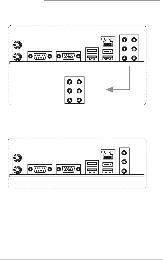
1.4 REAR PANEL CONNECTORS (VER 3.X)
Line In
Line Out
Mic In
Center
Re ar
Side
PS/2
Mouse
PS/2
Keyboard COM1 VGA1 USBX2USBX2
LAN
1.5 REAR PANEL CONNECTORS (VER 1.X)
Line In
Line Out
Mic In
PS/2
Mouse
PS/2
Keyboard COM1 VGA1 USBX2USBX2
LAN
GeForce 6100 AM2
5
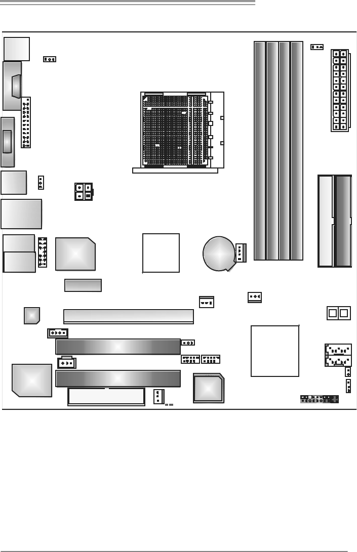
1.6 MOTHERBOARD LAYOUT (VER 3.X)
nForce
410
JKB MS1
J U SB1
JAUDIO1
J U SBLAN 1
BIOS
PCI-EX1_1
PCI-EX16
PCI1
FDD1
BAT1
JCOM1
JUSBV1
JCDIN1
Codec
LAN
JFAUDIO 1
JAT XPWR2
JSPDIF_OUT1
PCI2
JUSBV2
JUSB2 JUSB3
DIMMA1
JSFAN1
(Optio nal)JCI1
JCMOS1
IR ( optio nal)
IDE 1
IDE 2
JATXPWR1
JCFAN1
GeForce
6100
JV GA 1
JSATA2
JSATA1
DIMMB1
DIMMB2
DIMMA2
Socket A M2
JKBV1
JPANEL1
Super I/O
JSFAN 2
JNFAN1
JDDRII_22V
PWR SW1
RSTSW2
JPRNT1
LED_D1
LED_D2
Note: represents the 1■st pin.
Motherboard Manual
6
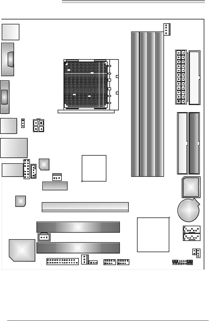
1.7 MOTHERBOARD LAYOUT (VER 1.X)
nForce
410
JKBMS1
JUSB1
JA U D IO 1
JU S BL AN1
BIO S
PCI-EX1_1
PCI-EX16
PC I1
FDD1
JCOM1
JUSBV1
JC DIN1
Cod ec
LAN
JFAUDIO1
JATX PWR2
JSP DIF_OUT1
PCI2
J USBV2 JUSB 2
J USB3
DIMMA1
JSFAN1
JC I1
(optional)
JCMOS1
IDE1
IDE2
JATXPW R1
JC FAN 1
GeForce
6100
JVGA1
J SATA2
J SATA1
DIMMB1
DIMMB2
DIMMA2
Socket A M2
JPANEL 1
Supe r I /O
JNFAN1
(opti onal )
JPRNT1
BAT1
Note: represents the 1■st pin.
GeForce 6100 AM2
7
CHAPTER 2: HARDWARE INSTALLATION
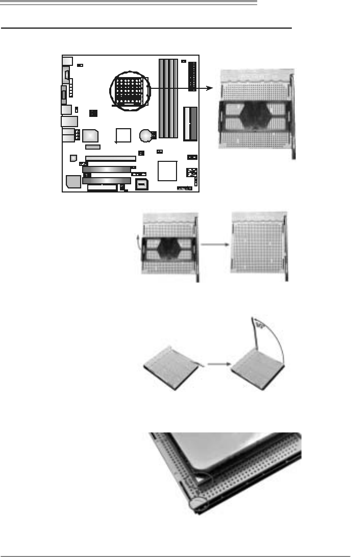
2.1 INSTALLING CENTRAL PROCESSING UNIT (CPU)
Step 1: Remove the socket protection cap.
Step 2: Pull the lever toward direction A from the socket and then raise the
lever up to a 90-degree angle.
Step 3: Look for the white triangle on socket, and the gold triangle on
CPU should point forwards this white triangle. The CPU will fit
only in the correct orientation.
Motherboard Manual
8
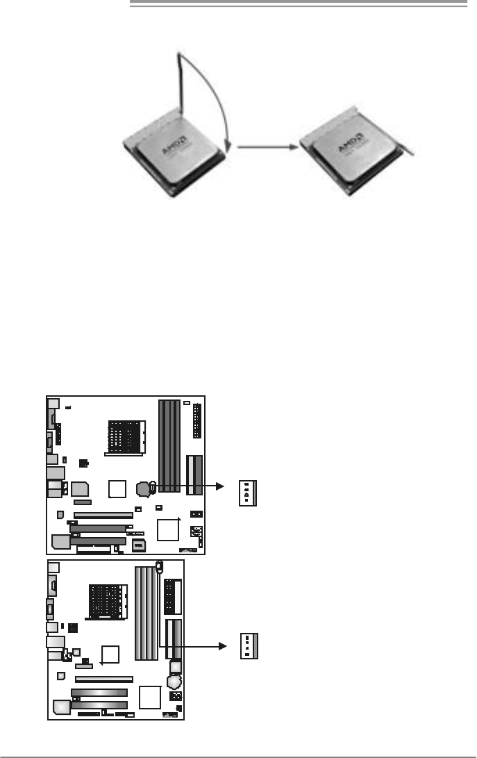
Step 4: Hold the CPU down firmly, and then close the lever toward direct
B to complete the installation.
Step 5: Put the CPU Fan on the CPU and buckle it. Connect the CPU
FAN power cable to the JCFAN1. This completes the installation.
2.2 FAN HEADERS
These fan headers support cooling-fans built in the computer. The fan
cable and connector may be different according to the fan manufacturer.
Connect the fan cable to the connector while matching the black wire to
pin#1.
JCFAN1: CPU Fan Header
Pin
Assignment
1 Ground
2 +12V
3 FAN RPM rate sense
JCFAN1
1
4
JCFAN1
1
4
4 Smart Fan Control
GeForce 6100 AM2
9
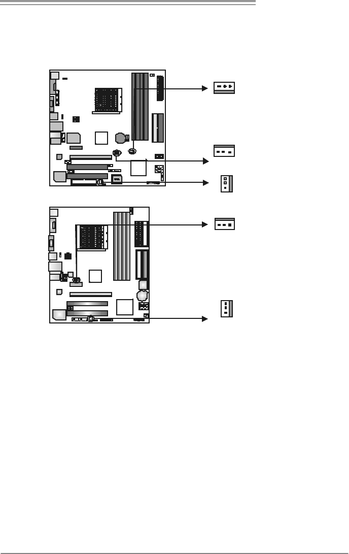
JNFAN1: North Bridge Fan Header (Optional for Ver 1.x)
JSFAN1: System Fan Header
JSFAN2: System Fan Header (Only for Ver 3.x)
JNFAN1/JSFAN1
Pin Assignment
1 Ground
2 +12V
3 FAN RPM rate
sense
JSFAN2
Pin Assignment
1 Ground
2 +12V
1
JNFAN1
(optional)
JSFAN1
1
1
JSFAN1
JSFAN2
1
1
JNFAN1
3 Ground
Note:
The JCFAN1 Supports 4-pin head c onnect or, and JSFAN1/J SFAN2/JNFAN1 support
3-pin head connector. When c onnecting with wires ont o co nnect ors, please note that the
red wire is the positi ve and shoul d be connected t o pi n#2, and th e bl ac k wire is Ground
and should be c onnec ted to GND.
JCFAN1 Supports s mart fan function
Motherboard Manual
10
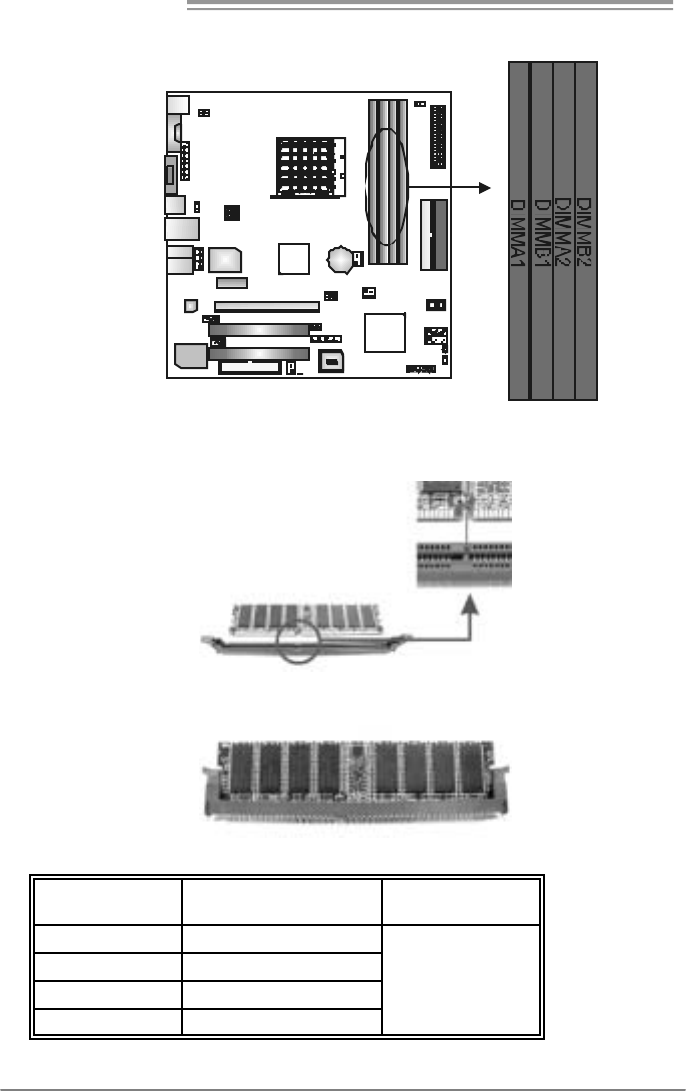
2.3 INSTALLING SYSTEM MEMORY
1. Unlock a DIMM slot by pressing the retaining clips outward. Align a
DIMM on the slot such that the notch on the DIMM matches the
break on the Slot.
2. Insert the DIMM vertically and firmly into the slot until the retaining
chip snap back in place and the DIMM is properly seated.
B. Memory Capacity
DIMM Socket
Location DDR Module To t a l Mem o r y
Size
DIMMA1 256MB/512MB/1024MB
DIMMB1 256MB/512MB/1024MB
DIMMA2 256MB/512MB/1024MB
DIMMB2 256MB/512MB/1024MB
Max is 4GB.

GeForce 6100 AM2
11
C. Dual Channel Memory installation
To trigger the Dual Channel f unction of the motherboard, the memory module
must meet the following requirements:
Install memory module of the same density in pairs, shown in the f ollowing
table.
Duual Channel Status DIMMA1 DIMMB1 DIMMA2 DIMMB2
Enabled O O X X
Enabled X X O O
Enabled O O O O
(O means memory installed, X means memory not installed.)
The DRAM bus width of the memory module must be the same (x8 or
x16)
Motherboard Manual
12
2.4 CONNECTORS AND SLOTS
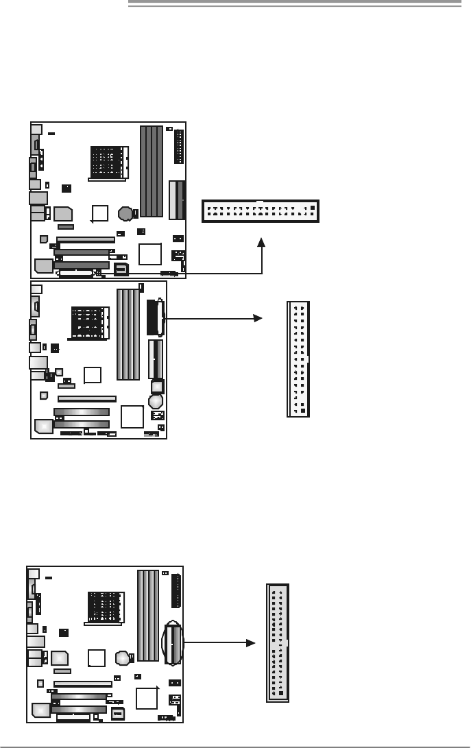
FDD1: Floppy Disk Connector
The motherboard prov ides a standard floppy disk connector that supports 360K,
720K, 1.2M, 1.44M and 2.88M floppy disk ty pes. This connector supports the
prov ided f loppy drive ribbon cables.
34
33
1
2
34
33
1
2
IDE1/IDE2: Hard Disk Connectors
The motherboard has a 32-bit Enhanced PCI IDE Controller that prov ides PIO
Mode 0~4, Bus Master, and Ultra DMA 33/66/100/133 f unctionality. It has two
HDD connectors IDE1 (primary) and IDE2 (secondary).
The IDE connectors can connect a master and a slav e driv e, so you can
connect up to four hard disk drives. The f irst hard drive should always be
connected to IDE1.
21
3940
IDE2 IDE1
GeForce 6100 AM2
13
PCI-Ex16: PCI-Express x16 Slot
- PCI-Express 1.0a compliant.
- Maximum theoretical realized bandwidth of 4GB/s simultaneously per
direction, f or an aggregate of 8GB/s totally.
PCI-Ex1_1: PCI-Express x1 Slot
- PCI-Express 1.0a compliant.
- Data transf er bandwidth up to 250MB/s per direction; 500MB/s in total.
- PCI-Express supports a raw bit-rate of 2.5Gb/s on the data pins.
- 2X bandwidth ov er the traditional PCI architecture.
PCI-EX1
_
1
PCIEX16
PCI1~PCI2: Peripheral Component Interconnect Slots
This motherboard is equipped with 2 standard PCI slots. PCI stands f or
Peripheral Component Interconnect, and it is a bus standard for expansion
cards. This PCI slot is designated as 32 bits.
PCI1
PCI2
Motherboard Manual
14
CHAPTER 3: HEADERS & JUMPERS SETUP
3.1 HOW TO SET UP JUMPERS
The illustration shows how to set up jumpers. When the jumper cap is
placed on pins, the jumper is “close”, if not, that means the jumper is
“open”.
Pin opened Pin closed Pin1-2 closed
3.2 DETAIL SETT INGS
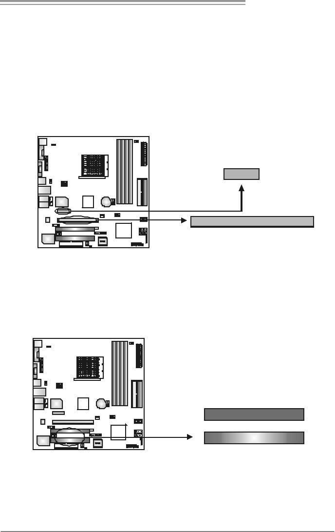
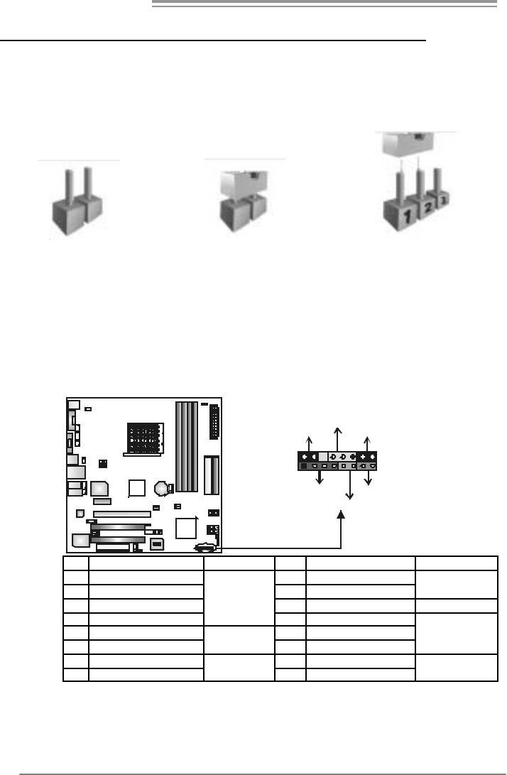
JPANEL1: Front Panel Header
This connector includes Power-on, Reset, HDD LED, Power LED, Sleep
button, and speaker. It allows user to connect the PC case’s front panel
switch functions.
1
SLP PWR
_
LED
On/Off
RST
HLED
SPK
++
+
2
-
-
15
16
Pin Assignment Function Pin Assignment Functio n
1 +5V 2 Sleep control
3 N/A 4 Ground Sleep button
5 N/A 6 N/A N/A
7 Speaker
Speaker
Connector
8 Power LED (+)
9 HDD LED (+) 10 Power LED (+)
11 HDD LED (-)
Hard drive
LED 12 Power LED (-)
Power LED
13 Ground 14 Power button
15 Reset control Reset button 16 Ground Power-on button
GeForce 6100 AM2
15
JIR1: IrDA Connector (Optional for Ver 3.x only)
The motherboard has a Infrared header that supports infrared signal
transmitting and receiv ing dev ice.
Pin
Assignment
1 +5V
2 IRTX
3 Ground
4 IRRX
13
24
IR(optional)
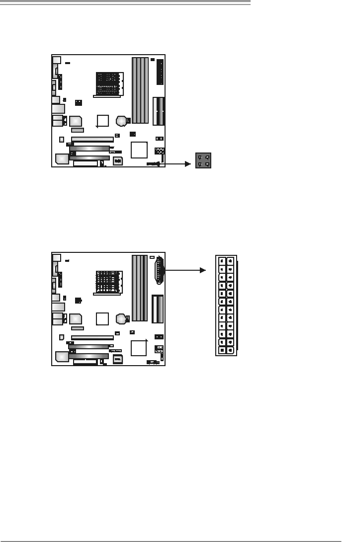
ATX Power Source Connector: JATXPWR1
JATXPWR1 allows user to connect 24-pin power connector on the ATX power
supply.
1
12 24
13
Pin Assignment Pin Assignment
1 +3.3V 13 +3.3V
2 +3.3V 14 -12V
3 Ground 15 Ground
4 +5V 16 PS_ON
5 Ground 17 Ground
6 +5V 18 Ground
7 Ground 19 Ground
8 PW_OK 20 NC
9 Standby Voltage+5V 21 +5V
10 +12V 22 +5V
11 +12V 23 +5V
12 +3.3V 24 Ground
Motherboard Manual
16
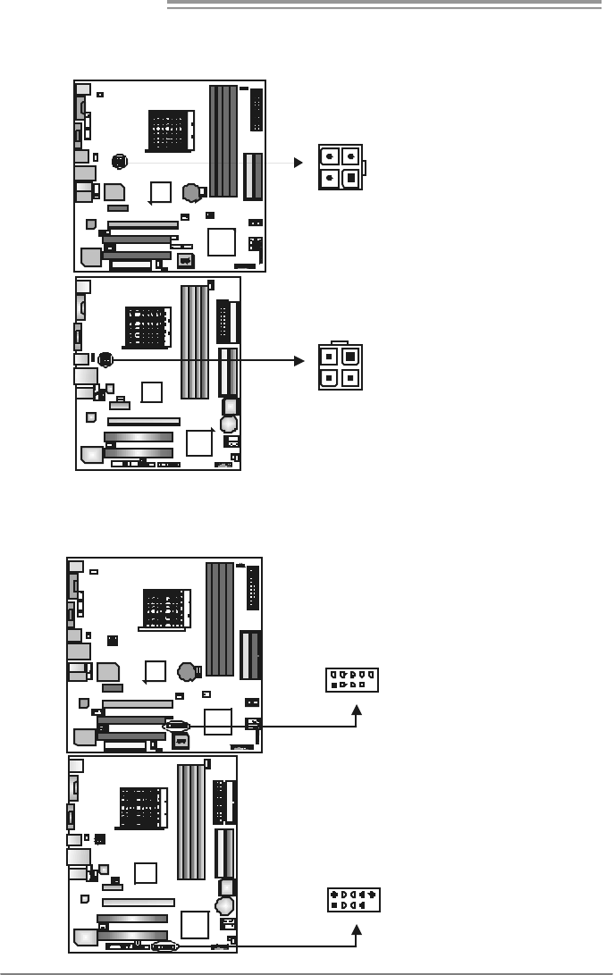
JATXPW R2: ATX Powe r Sou rce C onne ctor
By connecting this connector, it will provide +12V to CPU power circuit.
Pin
Assignment
1 +12V
2 +12V
3 Ground
2
4
1
3
2
41
3
4 Ground
JUSB2/JUSB3: Headers for USB 2.0 Ports at Front Panel
This header allows user to connect additional USB cable on the PC f ront panel,
and also can be connected with internal USB devices, like USB card reader.
Pin
Assignment
1 +5V (fused)
2 +5V (fused)
3 USB-
4 USB-
5 USB+
6 USB+
7 Ground
8 Ground
9 Key
1
2
9
10
JUSB3 JUSB2
1
2
9
10
JUSB2 JUSB3
10 NC
GeForce 6100 AM2
17
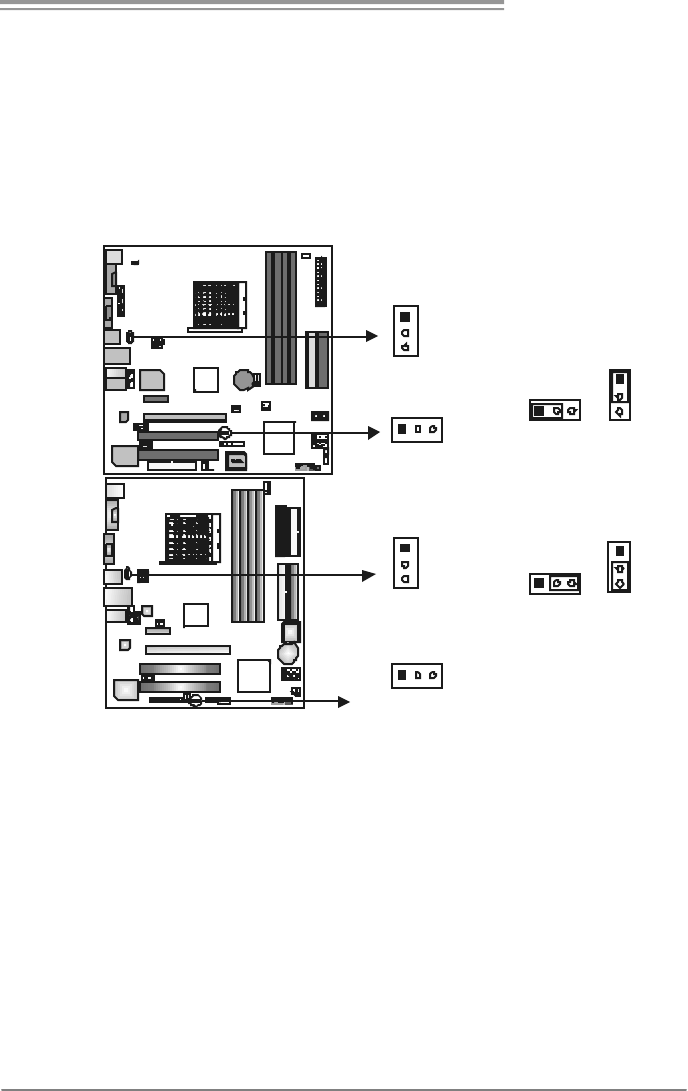
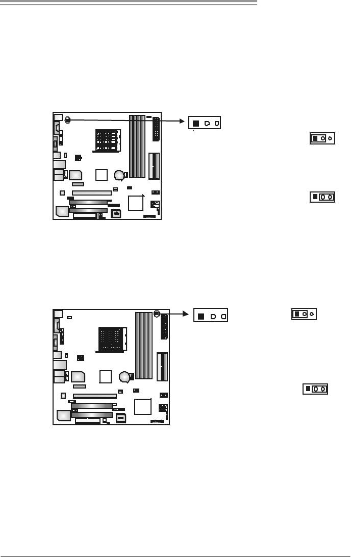
JUSBV1/JUSBV2: Powe r Source Heade rs for USB Ports
Pin 1-2 Close:
JUSBV1: +5V for USB ports at JUSBLAN1.
JUSBV2: +5V for USB ports at f ront panel (JUSB2/JUSB3).
Pin 2-3 Close:
JUSBV1: USB ports at JUSBLAN1 are powered by +5V standby voltage.
JUSBV2: USB ports at front panel (JUSB2/JUSB3) are powered by +5V
standby v oltage.
31
1
3
Pin 1-2 close
1
JUSBV1
JUSBV2
1
1
JUSBV1
JUSBV2
1
3
1
1
3
Pin 2-3 close
Note:
In order to support this function “Power-On s ystem vi a USB devic e,” “JUSBV1/ JUSBV2”
jumper cap should be plac ed on Pin 2-3 indi viduall y.
Motherboard Manual
18
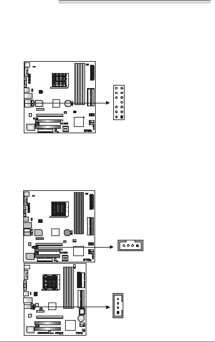
JFAUDIO1: Front Panel Audio Header
This header allows user to connect the front audio output cable with the PC f ront
panel. It will disable the output on back panel audio connectors.
Pin Assignment
1 Mic in/center
2 Ground
3 Mic power/Bass
4 Audio power
5 Right line out/
Speaker out Right
6 Right line out/
Speaker out Right
7 Reserved
8 Key
9 Left line out/
Speaker out Left
10 Left line out/
Speaker out Left
11 Right line in/
Rear speaker Right
12 Right line in/
Rear speaker Right
13 Left line in/
Rear speaker Left
14
2
13
1
14 Left line in/
Rear speaker Left
JCDIN1: CD-ROM Audio-in Connector
This connector allows user to connect the audio source f rom the v ariaty dev ices,
like CD-ROM, DVD-ROM, PCI sound card, PCI TV turner card etc..
Pin
Assignment
1 Left Channel
Input
2 Ground
3 Ground
1
4
14
4 Right Channel
Input
GeForce 6100 AM2
19
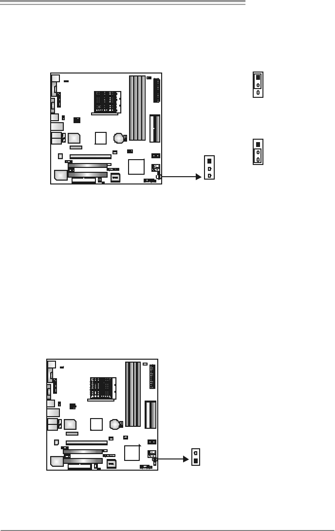
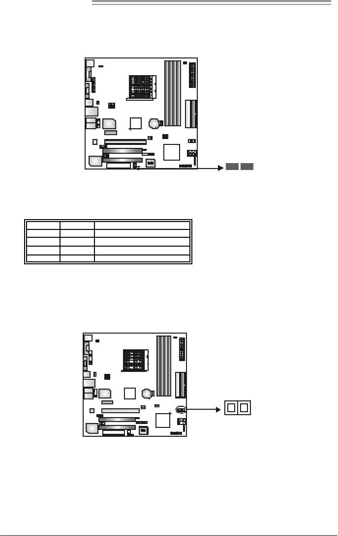
JCMOS1: Clear CMOS Header
By placing the jumper on pin2-3, it allows user to restore the BIOS saf e setting
and the CMOS data, please carefully f ollow the procedures to avoid damaging
the motherboard.
1
3
Pin 1-2 Close:
Normal Operation (default).
1
1
3
Pin 2-3 Close:
Clear CMOS data.
※ Clear CMOS Procedures:
1. Remov e AC power line.
2. Set the jumper to “Pin 2-3 close”.
3. Wait for five seconds.
4. Set the jumper to “Pin 1-2 close”.
5. Power on the AC.
6. Reset y our desired password or clear the CMOS data.
JCI1: Chassis O pen Heade r (optional)
This connector allows system to monitor PC case open status. If the signal has
been triggered, it will record to the CMOS and show the message on next
boot-up.
Pin
Assignment
1 Case open signal
1
2 Ground
Motherboard Manual
20
JSATA1~JSATA2: Serial ATA Connectors
The motherboard has a PCI to SATA Controller with 2 channels SATA interf ace,
it satisfies the SATA 2.0 spec and with transfer rate of 3.0Gb/s.
Pin
Assignment
1 Ground
2 TX+
3 TX-
4 Ground
5 RX-
6 RX+
714
JSATA2
JSATA1
7 Ground
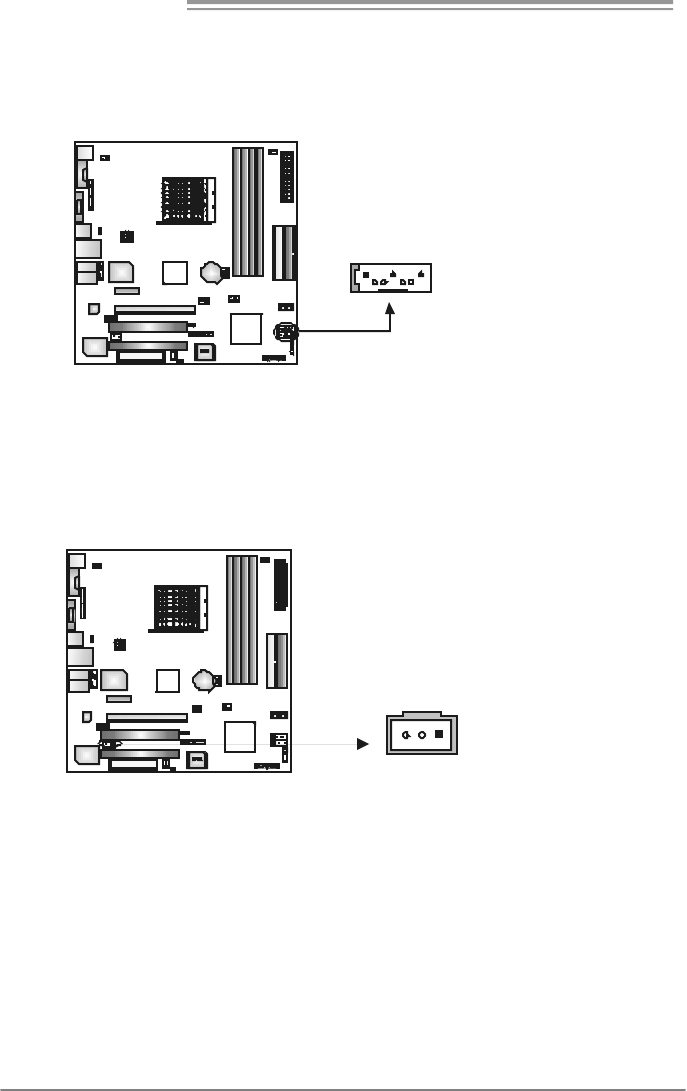
JSPDIF_O UT1: Digital Audio-out Connector
This connector allows user to connect the PCI bracket SPDIF output header.
Pin
Assignment
1 +5V
2 SPDIF_OUT
13
3 Ground
GeForce 6100 AM2
21
Power Source Selection Headers for Keyboard/Mouse: JKBMSV1
(Only for Ver 3.x)
Pin 1-2 Close:
JKBMSV1: +5V for PS/2 key board and mouse。
Pin 2-3 Close:
JKBMSV1: PS/2 keyboard and mouse are powered with +5V standby
v oltage.
13
Pin 1-2 close
13
Pin 2-3 close
Header to adjust Memory Voltage: JDDR_II>2.2V (Only for Ver 3.x)
When adjusting Memory Voltage, please place the jumper to pin2-3 Closed. The
Def ault setting is Pin 1-2 Closed.
13
Pin 1-2 Cl ose:
Memory Voltage
controll ed by BIOS
(default).
1
13
Pin 2-3 Cl ose:
Memory voltage
Overclocking
Note:
1. When “JDDR_II>2.2V” jumper cap is placed on Pin 1-2, memory v oltage
can be manually adjusted under CMOS setup.
2. When “JDDR_II>2.2V” jumper cap is placed on Pin 2-3, memory v oltage
will be f ixed at 2.2V automatically, and can’t be adjusted under COMS
setup.
Bef ore setting memory v oltage ov erclocking, please ensure that y our DDRII
memory modules are able to support 2.2V. (Consulting your DDR supplier)
Motherboard Manual
22
On-Board LED Indicators (Only for Ver 3.x)
There are 2 LED indicators on the motherboard to show system status.
LED
_
D1
LED
_
D2
LED_D1 and LED_D2:
These 2 LED indicate system power on diagnostics.
Please ref er to the table below for different messages:
LED_D1 LED_D2 Message
ON ON Normal
ON OFF VGA Error
OFF ON Memory Error
OFF OFF Abnorma l: CPU / Chipset error.
On-Board Buttons (Optional for Ver 3.x only)
There are 2 on-board buttons.
PWRSW1
RSTSW2
PWRSW1:
This is an on-board Power On/Off button.
RSTSW2:
This is an on-board Reset button.
GeForce 6100 AM2
23
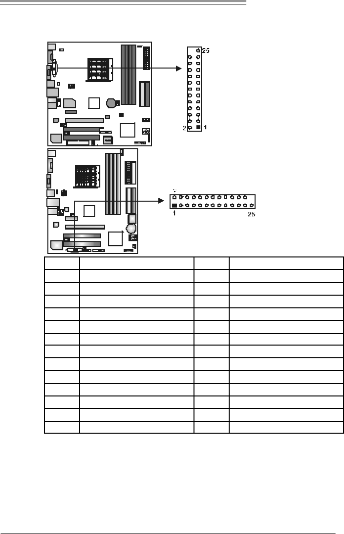
JPRNT1: Printer Port Connector
This header allows you to connector printer on the PC.
Pin Assignment Pin Assignment
1 -Strobe 14 Ground
2 -ALF 15 Data 6
3 Data 0 16 Ground
4 -Error 17 Data 7
5 Data 1 18 Ground
6 -Init 19 -ACK
7 Data 2 20 Ground
8 -Scltin 21 Busy
9 Data 3 22 Ground
10 Ground 23 PE
11 Data 4 24 Ground
12 Ground 25 SCLT
13 Data 5
Motherboard Manual
24
CHAPTER 4: NVIDIA RAID FUNCTIONS
4.1 OPERATION SYSTEM
z Supports Windows XP Home/Prof essional Edition, and Windows 2000 Prof essional.
4.2 RAID ARRAYS
NVRAID supports the f ollowing ty pes of RAID arrays:
RAID 0: RAID 0 defines a disk striping scheme that improves disk read and write times for
many applications.
RAID 1: RAID 1 defines techniques for mirroring data.
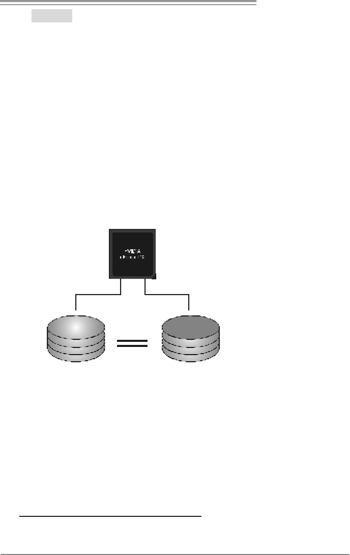
4.3 HOW RAID WORKS
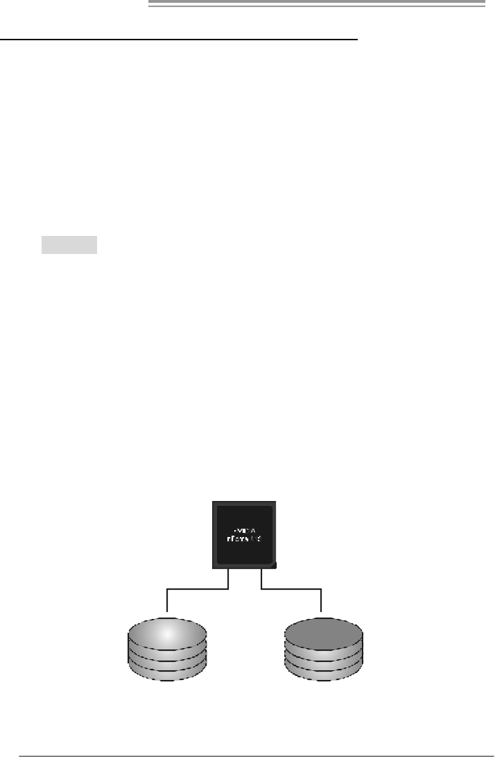
RAID 0:
The controller “stripes” data across multiple drives in a RAID 0 array system. It breaks
up a large file into smaller blocks and performs disk reads and writes across multiple
drives in parallel. The size of each block is determined by the stripe size parameter,
which you set during the creation of the RAID set based on the system environment. This
technique reduces overall disk access time and offers high bandwidth.
Features and Benefits
Drives: Minimum 1, and maximum is up to 6 or 8. Depending on the
platf orm.
Uses: Intended for non-critical data requiring high data throughput, or any
env ironment that does not require f ault tolerance.
Benefits: prov ides increased data throughput, especially f or large files. No
capacity loss penalty f or parity.
Drawbacks: Does not deliver any fault tolerance. If any drive in the array
f ails, all data is lost.
Fault Tolerance: No.
Bloc k 1
Block 3
Block 5
Block 2
Block 4
Block 6
GeForce 6100 AM2
25
RAID 1:
Every read and write is actually carried out in parallel across 2 disk drives in a RAID 1
array system. The mirrored (backup) copy of the data can reside on the same disk or on
a second redundant drive in the array. RAID 1 provides a hot-standby copy of data if
the active volume or drive is corrupted or becomes unavailable because of a hardware
failure.
RAID techniques can be applied for high-availability solutions, or as a form of
automatic backup that eliminates tedious manual backups to more expensive and less
reliable media.
Features and Benefits
Drives: Minimum 2, and maximum is 2.
Uses: RAID 1 is ideal for small databases or any other application that
requires f ault tolerance and minimal capacity.
Benefits: Prov ides 100% data redundancy. Should one driv e f ail, the
controller switches to the other drive.
Drawbacks: Requires 2 driv es for the storage space of one driv e.
Perf ormance is impaired during driv e rebuilds.
Fault Tolerance: Yes.
Bloc k 1
Block 2
Block 3
Block 1
Block 2
Block 3
※ For more detailed setup information, please refer to the Driver CD, or go to
http://www.nvidia.com/page/pg_20011106217193.html to download NVIDIA nForce Tutorial Flash.
Motherboard Manual
26
CHAPTER 5: USEFUL HELP
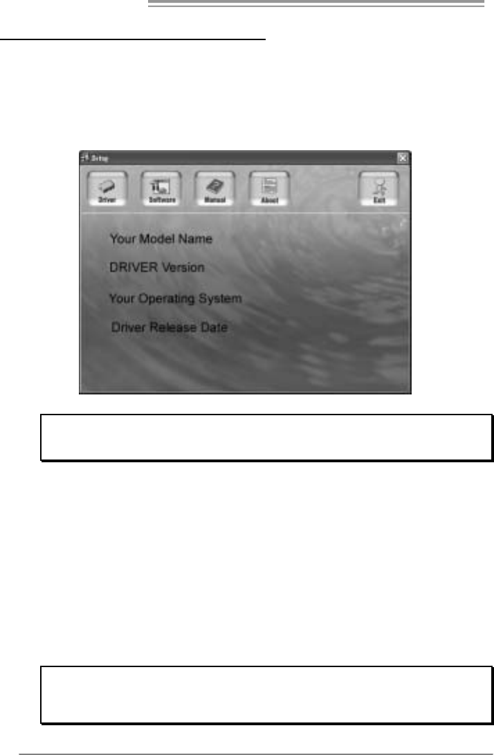
5.1 DRIVER INSTALLATION NOTE
After you installed your operating system, please insert the Fully Setup
Driver CD into your optical drive and install the driver for better system
performance.
You will see the following window after you insert the CD
The setup guide will auto detect your motherboard and operating system.
Note:
If this window didn’t show up aft er you ins ert the Driver CD, ple ase use file brows er to
locate and execute the file SETUP.EXE under your optical drive.
A. Driver Installation
To install the driver, please click on the Driver icon. The setup guide will
list the compatible driver for your motherboard and operating system.
Click on each device driver to launch the installation program.
B. Software Installation
To install the software, please click on the Software icon. The setup guide
will list the software available for your system, click on each software title
to launch the installation program.
C. Manual
Aside from the paperback manual, we also provide manual in the Driver
CD. Click on the Manual icon to browse for available manual.
Note:
You will need Acrobat Reader to open the manual file. Please download the latest version
of Acrobat Reader software from
http://www.adobe.com/products/acrobat/readstep2.html
GeForce 6100 AM2
27
5.2 AWARD BIOS BEEP CODE
Beep Sound Meaning
One long beep followed by two short
beeps Video card not found or v ideo card
memory bad
High-low siren sound CPU overheated
System will shut down automatically
One Short beep when system boot-up No error found during POST
Long beeps every other second No DRAM detected or install
5.3 EXT RA INFORMATION
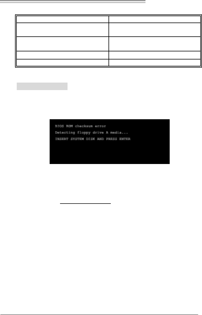
A. BIOS Update
After you fail to update BIOS or BIOS is invaded by virus, the
Boot-Block function will help to restore BIOS. If the following message
is shown after boot-up the system, it means the BIOS contents are
corrupted.
In this Case, please follow the procedure below to restore the BIOS:
1. Make a bootable floppy disk.
2. Download the Flash Utility “AWDFLASH.exe” from the Biostar
website: www.biostar.com.tw
3. Confirm motherboard model and download the respectively BIOS
from Biostar website.
4. Copy “AWDFLASH.exe” and respectively BIOS into floppy disk.
5. Insert the bootable disk into floppy drive and press Enter.
6. System will boot-up to DOS prompt.
7. Type “Awdflash xxxx.bf/sn/py/r” in DOS prompt.
(xxxx means BIOS name.)
8. System will update BIOS automatically and restart.
9. The BIOS has been recovered and will work properly.

Motherboard Manual
28
B. CPU Overheated
If the system shutdown automatically after power on system for
seconds, that means the CPU protection function has been activated.
When the CPU is over heated, the motherboard will shutdown
automatically to avoid a damage of the CPU, and the system may not
power on again.
In this case, please double check:
1. The CPU cooler surface is placed evenly with the CPU surface.
2. CPU fan is rotated normally.
3. CPU fan speed is fulfilling with the CPU speed.
After confirmed, please follow steps below to relief the CPU
0protection function.
1. Remove the power cord from power supply for seconds.
2. Wa i t fo r second s.
3. Plug in the power cord and boot up the system.
Or you can:
1. Clear the CMOS data.
(See “Close CMOS Header: JCMOS1” section)
2. Wa i t fo r second s.
3. Power on the system again.

GeForce 6100 AM2
29
5.4 TROUBLESHOOTING
Probable Solution
1. No power to the system at all
Power light don’t illuminate, f an
inside power supply does not turn
on.
2. Indicator light on key board does
not turn on.
1. Make sure power cable is
securely plugged in.
2. Replace cable.
3. Contact technical support.
System inoperativ e. Keyboard lights
are on, power indicator lights are lit,
and hard driv e is spinning.
Using even pressure on both ends of
the DIMM, press down firmly until the
module snaps into place.
System does not boot from hard disk
driv e, can be booted f rom optical driv e. 1. Check cable running from disk to
disk controller board. Make sure
both ends are securely plugged
in; c hec k t he driv e ty pe in t he
standard CMOS setup.
2. Backing up the hard drive is
extremely important. All hard
disks are capable of breaking
down at any time.
System only boots f rom optical driv e.
Hard disk can be read and applications
can be used but booting from hard disk
is impossible.
1. Back up data and applications
files.
2. Ref ormat the hard driv e.
Re-install applications and data
using backup disks.
Screen message says “Invalid
Conf iguration” or “CMOS Failure.” Rev iew system’s equipment. Make sur
e
correct inf ormation is in setup.
Cannot boot system after installing
second hard driv e. 1. Set master/slave jumpers
correctly.
2. Run SETUP program and select
correct driv e types. Call the drive
manuf acturers f or compatibility
with other drives.

Motherboard Manual
30
CHAPTER 6: WARPSPEEDER™
6.1 INTRODUCTION
[WarpSpeeder™], a new powerful control utility, features three
user-friendly functions including Overclock Manager, Overvoltage
Manager, and Hardware Monitor.
With the Overclock Manager, users can easily adjust the frequency they
prefer or they can get the best CPU performance with just one click. The
Overvoltage Manager, on the other hand, helps to power up CPU core
voltage and Memory voltage. The cool Hardware Monitor smartly indicates
the temperatures, voltage and CPU fan speed as well as the chipset
information. Also, in the About panel, you can get detail descriptions about
BIOS model and chipsets. In addition, the frequency status of CPU,
memory, AGP and PCI along with the CPU speed are synchronically
shown on our main panel.
Moreover, to protect users' computer systems if the setting is not
appropriate when testing and results in system fail or hang,
[WarpSpeeder™] technology assures the system stability by automatically
rebooting the computer and then restart to a speed that is either the
original system speed or a suitable one.
6.2 SYSTEM REQUIREMENT
OS Support: Windows 98 SE, Windows Me, Windows 2000, Windows XP
DirectX: DirectX 8.1 or above. (The Windows XP operating system
includes DirectX 8.1. If you use Windows XP, you do not need to install
DirectX 8.1.)
GeForce 6100 AM2
31
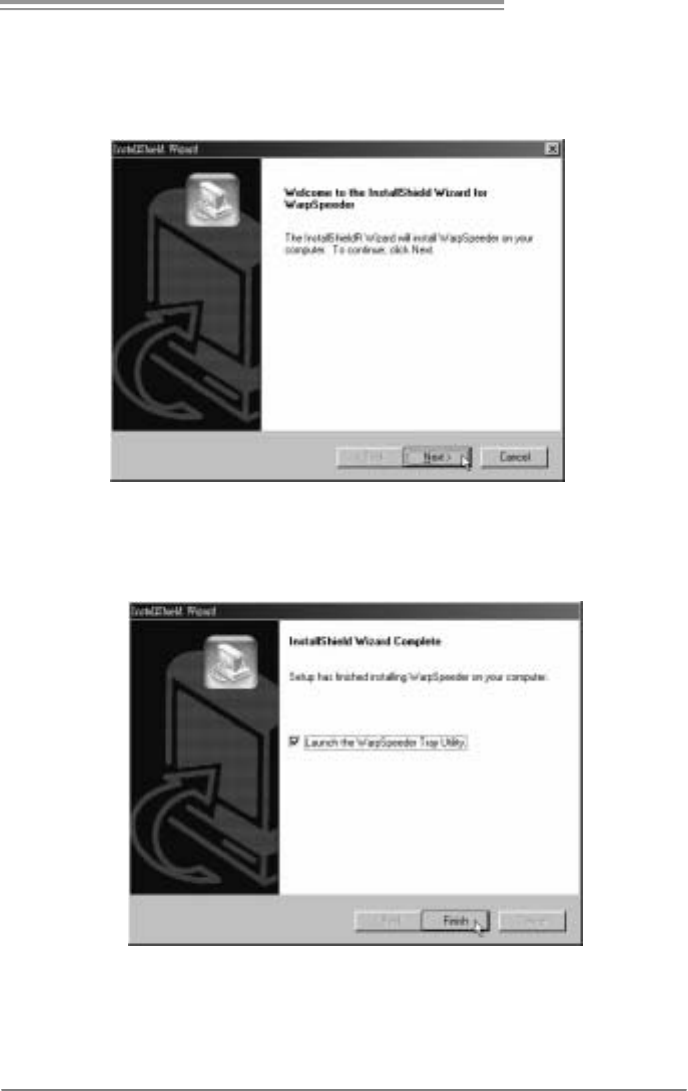
6.3 INSTALLATION
1. Execute the setup execution file, and then the following dialog will pop
up. Please click “Next” button and follow the default procedure to
install.
2. When you see the following dialog in setup procedure, it means setup
is completed. If the “Launch the WarpSpeeder Tray Utility” checkbox
is checked, the Tray Icon utility and [WarpSpeeder™] utility will be
automatically and immediately launched after you click “Finish”
button.
Usage:
The following figures are just only for reference, the screen printed in
this user manual will change according to your motherboard on hand.
Motherboard Manual
32
6.4 WARPSPEEDER™
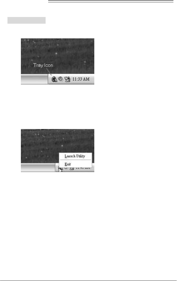
1. Tray Icon:
Whenever the Tray Icon utility is launched, it will display a little tray
icon on the right side of Windows Taskbar.
This utility is responsible for conveniently invoking [WarpSpeeder™]
Utility. You can use the mouse by clicking the left button in order to
invoke [WarpSpeeder™] directly from the little tray icon or you can
right-click the little tray icon to pop up a popup menu as following
figure. The “Launch Utility” item in the popup menu has the same
function as mouse left-click on tray icon and “Exit” item will close
Tray Icon utility if selected.
GeForce 6100 AM2
33
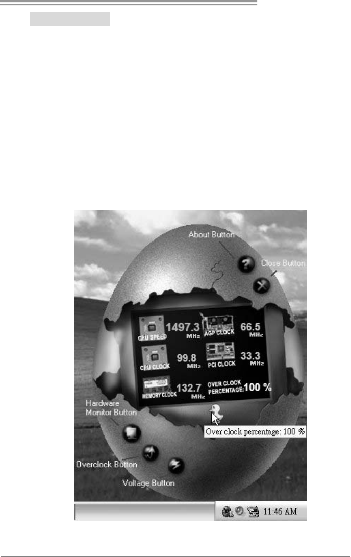
2. Main Panel
If you click the tray icon, [WarpSpeeder™] utility will be invoked.
Please refer to the following figure; the utility’s first window you will
see is Main Panel.
Main Panel contains features as follows:
a. Di spl ay the CPU Sp ee d, CPU external cl o ck, M em ory clo ck, AGP cl ock,
and PCI clock information.
b. Contains About, Voltage, Overclock, and Hardware Monitor Buttons for
invoking respective panels.
c. With a user-friendly Status Animation, it can represent 3 overclock
percentage stages:
Man walking→overclock percentage from 100% ~ 110 %
Panther running→overclock percentage from 110% ~ 120%
Car racing→overclock percentage from 120% ~ above
Motherboard Manual
34
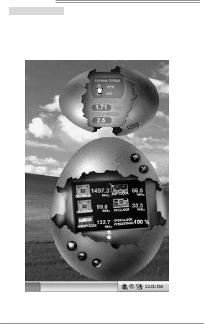
3. Voltage Panel
Click the Voltage button in Main Panel, the button will be highlighted
and the Voltage Panel will slide out to up as the following figure.
In this panel, you can decide to increase CPU core voltage and
Memory voltage or not. The default setting is “No”. If you want to get
the best performance of overclocking, we recommend you click the
option “Yes”.
GeForce 6100 AM2
35
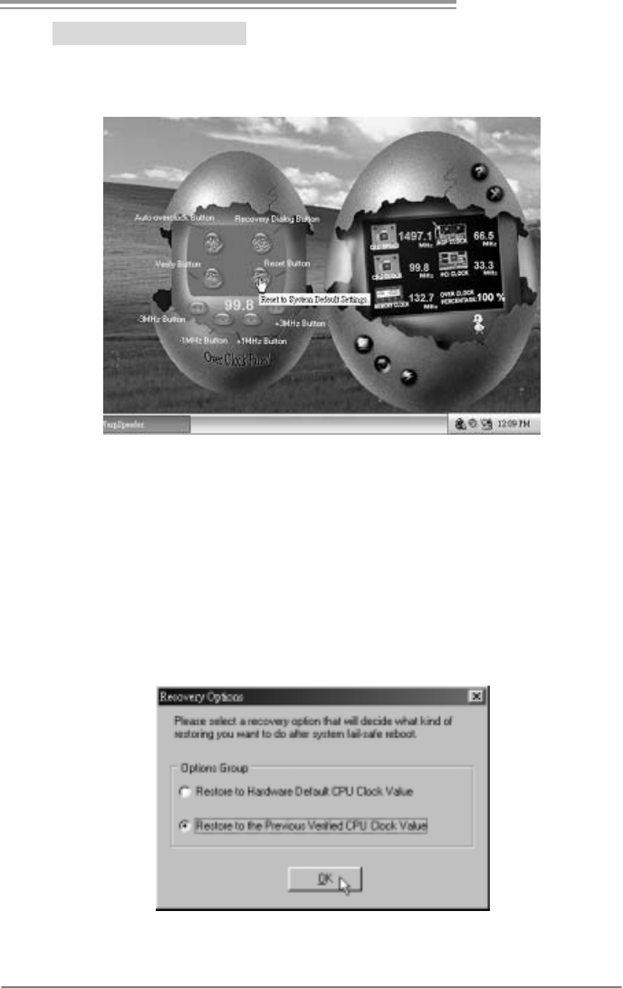
4. Overclock Panel
Click the Overclock button in Main Panel, the button will be
highlighted and the Overclock Panel will slide out to left as the
following figure.
Overclock Panel contains the these features:
a. “–3MHz button”, “-1MHz button”, “+1MHz button”, and “+3MHz button”:
provide user the ability to do real-time overclock adjustment.
Warning:
Manually overclock is potentially dangerous, especially when the
ov erclocking percentage is over 110 %. We strongly recommend you
v erify ev ery speed you overclock by click the Verify button. Or, you can
just click Auto ov erclock button and let [WarpSpeeder™] automatically
gets the best result f or y ou.
b. “Recovery Dialog button”: Pop up the following dialog. Let user select
a restoring way if system need to do a fail-safe reboot.
Motherboard Manual
36
c. “Auto-overclock button”: User can click this button and
[WarpSpeeder™] will set the best and stable performance and
frequency automatically. [WarpSpeeder™] utility will execute a
series of testing until system fail. Then system will do fail-safe
reboot by using Watchdog function. After reboot, the
[WarpSpeeder™] utility will restore to the hardware default
setting or load the verified best and stable frequency according
to the Recovery Dialog’s setting.
d. “Verify button”: User can click this button and [WarpSpeeder™]
will proceed a testing for current frequency. If the testing is ok,
then the current frequency will be saved into system registry. If
the testing fail, system will do a fail-safe rebooting. After reboot,
the [WarpSpeeder™] utility will restore to the hardware default
setting or load the verified best and stable frequency according
to the Recovery Dialog’s setting.
Note:
Because the testing programs, invoked in Auto-overclock and Verify,
include DirectDraw, Direct3D and DirectShow tests, the DirectX 8.1 or
newer runtime library is required. And please make sure y our display
card’s color depth is High color (16 bit) or True color( 24/32 bit ) that is
required f or Direct3D rendering.
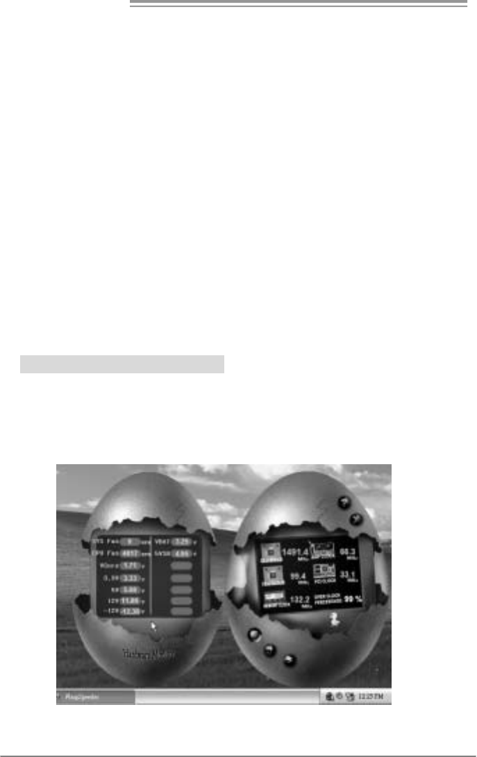
5. Hardware Monitor Panel
Click the Hardware Monitor button in Main Panel, the button will be
highlighted and the Hardware Monitor panel will slide out to left as
the following figure.
In this panel, you can get the real-time status information of your
system. The information will be refreshed every 1 second.
GeForce 6100 AM2
37
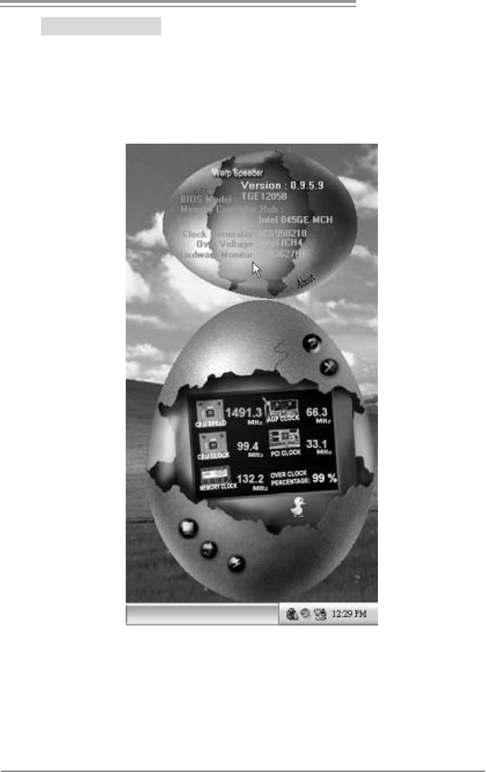
6. About Panel
Click the “about” button in Main Panel, the button will be highlighted
and the About Panel will slide out to up as the following figure.
In this panel, you can get model name and detail information in hints
of all the chipset that are related to overclocking. You can also get
the mainboard’s BIOS model and the Version number of
[WarpSpeeder™] utility.
Note :
Because the overclock, overvoltage, and hardware monitor features
are controlled by several separate chipset, [WarpSpeeder™] divide
these features to separate panels. If one chipset is not on board, the
correlative button in Main panel will be disabled, but will not interfere
other panels’ functions. This property can make [WarpSpeeder™]
utility more robust.

Motherboard Manual
38
APPENDENCIES: SPEC IN OTHER LANGUAGE
GERMAN
Ver 3.x Ver 1.x
CPU
Sockel AM2
AMD Athlon 64 / Athlon 64 FX / Sempron
Prozessoren
Die AMD 64-Architektur unterstützt eine 32-Bit-
und 64-Bit-Datenverarbeitung
Unterstützt Hyper Transport und Cool’n’Quiet
Sockel AM2
AMD Athlon 64 / Athlon 64 FX / Sempron
Prozessoren
Die AMD 64-Architektur unterstützt eine 32-Bit-
und 64-Bit-Datenverarbeitung
Unterstützt Hyper Transport und Cool’n’Quiet
FSB Unterstützt HyperTransport mit einer Bandbreite
von bis z u 1000 MHz
Unterstützt HyperTransport mit einer Bandbreite
von bis z u 1000 MHz
Chipsatz GeForce 6100
nForce 4 10
GeForce 6100
nForce 4 10
Super E/A
ITE 8712F / 8716F
Bietet die häufig verwendeten alten Super
E/A-Funktionen.
Low Pin Count-Schnittstelle
Umgebungskontrolle,
Hardware-Überwachung
Lüfterdrehzahl-Controller
"Smart Guardian"-Funktion von ITE
ITE 8712F / 8716F
Bietet die häufig verwendeten alten Super
E/A-Funktionen.
Low Pin Count-Schnittstelle
Umgebungskontrolle,
Hardware-Überwachung
Lüfterdrehzahl-Controller
"Smart Guardian"-Funktion von ITE
Arbeitsspeich
er
DDR2 DIMM-Steckplätze x 4
Jeder DIMM unterstützt 256/512MB & 1GB
DDR2.
M ax. 4GB A rbeit ss peic her
Dual-Kanal DDR2 Speichermodul
Unterstützt DDR2 400 / 533 / 667 / 800
registrierte DIMMs. ECC DIMMs werden nicht
unterstützt.
DDR2 DIMM-Steckplätze x 4
Jeder DIMM unterstützt 256/512MB & 1GB
DDR2.
M ax. 4GB A rbeit ss peic her
Dual-Kanal DDR2 Speichermodul
Unterstützt DDR2 400 / 533 / 667 / 800
registrierte DIMMs. ECC DIMMs werden nicht
unterstützt.
Grafik
Integrierter Geforce 6100-Chipsatz
Max. 256 MB gemeinsam benutzter
Videospeicher
Integrierter Geforce 6100-Chipsatz
Max. 256 MB gemeinsam benutzter
Videospeicher
IDE
Integrierter IDE-Controller
Ultra DMA 33 / 66 / 100 / 133 Bus
Master-Modus
Unterstützt PIO-Modus 0~4,
Integrierter IDE-Controller
Ultra DMA 33 / 66 / 100 / 133 Bus
Master-Modus
Unterstützt PIO-Modus 0~4,
SA TA II
I nt e gr i ert e r S e ri al ATA - Con tr oll e r
Datentransferrate bis zu 3Gb/s
Konform mit der SATA-Spezifikation Version 2.0.
I nt e gr i ert e r S e ri al ATA - Con tr oll e r
Datentransferrate bis zu 3Gb/s
Konform mit der SATA-Spezifikation Version 2.0.
LAN Realtek 8100C
10 / 100 Mb/s Auto-Negotiation
Realtek 8201CL PHY
10 / 100 Mb/s Auto-Negotiation

GeForce 6100 AM2
39
Ver 3.x Ver 1.x
Audio-Codec
ALC 850
8-Kanal-Audioausgabe
AC’97 Version 2.3
ALC 655 / 658 (optional)
6-Kanal-Audioausgabe
AC’97 Version 2.3
PCI-Steckplatz x2 PCI-Steckplatz x2
PCI Express x16 Steckplatz x1 PCI Express x16 Steckplatz x1
Steckplätze
PCI Express x 1-Steckplatz x1 PCI Express x 1-Steckplatz x1
Diskettenlaufw erkansc hluss x1 Diskett enlaufw erkansc hluss x1
Druc keransc hluss Ansc hluss x1 Druc keransc hluss A nsc hluss x1
IDE-Ansc hluss x2 IDE-Ansc hluss x2
SATA-Anschluss x2 SATA-Anschluss x2
Fronttafelanschluss x1 Fronttafelanschluss x1
Front-A udioansc hluss x1 Front -Audioansc hluss x1
CD-IN-Ansc hluss x1 CD-IN-Ansc hluss x1
S/PDIF-Ausgangsanschluss x1 S/PDIF-Ausgangsanschluss x1
CPU-Lüfter-Sockel x1 CPU-Lüfter-Sockel x1
System-Lüfter-Sockel x3 System-Lüfter-Sockel x1
"Gehäuse offen"-Sockel (optional) x1 "Gehäuse offen"-Sockel (optional) x1
"CMOS löschen"-Sockel x1 "CMOS löschen"-Sockel x1
USB-Ansc hluss x2 USB-Ansc hluss x2
Stromanschluss (24-polig) x1 Stromanschluss (24-polig) x1
Onboard-Ans
chluss
Stromanschluss (4-polig) x1 Stromanschluss (4-polig) x1
Rückseiten-E
/A
PS/2-Tastatur x1
PS/2-Maus x1
Serieller Ansc hluss x1
VGA-Anschluss x1
LA N-A nsc hluss x1
USB-Ansc hluss x4
Audioansc hluss x6
PS/2-Tastatur x1
PS/2-Maus x1
Serieller Ansc hluss x1
VGA-Anschluss x1
LA N-A nsc hluss x1
USB-Ansc hluss x4
Audioansc hluss x3
Platinengröße
. 244 mm (B) X 244 mm (L) 210 mm (B) X 244 mm (L)
Sonderfunkti
onen
NVIDIA nTunes
Unterstützt RAID 0 / 1
NVIDIA nTunes
Unterstützt RAID 0 / 1
OS-Unterstüt
zung
Windows 2K / XP
Biostar behält sich das Recht vor, ohne
Ankündigung die Unterstützung für ein
Betriebssystem hinzuzufügen oder zu
entfernen.
Windows 2K / XP
Biostar behält sich das Recht vor, ohne
Ankündigung die Unterstützung für ein
Betriebssystem hinzuzufügen oder zu
entfernen.

Motherboard Manual
40
FRANCE
Ver 3.x Ver 1.x
UC
Socket AM2
Process eurs AMD At hlon 64 / At hl on 64 FX /
Sempron
L'architecture AMD 64 permet le calcul 32 et 64
bits
Prend en charge Hy
p
er Tr a ns
p
ort et Cool’n’
Q
uiet
Socket AM2
Process eurs AMD At hlon 64 / At hl on 64 FX /
Sempron
L'architecture AMD 64 permet le calcul 32 et 64
bits
Prend en char
g
e H
yp
er Tr a ns
p
ort et Cool’n’
Q
uiet
Bus frontal Prend en charge Hyper Transport jusqu'à une
bande passante de 1000 MHz
Prend en charge Hyper Transport jusqu'à une
bande passante de 1000 MHz
Chipset GeForce 6100
nForce 4 10
GeForce 6100
nForce 4 10
Graphiques Integré dans la c hipset GeForce 6100
Mémoire vidéo partagée maximale de 256 Mo
Integré dans la chipset GeForce 6100
Mémoire vidéo partagée maximale de 256 Mo
Super E/S
ITE 8712F / 8716F
Fournit la fonctionnalité de Super E/S
patrimoniales la plus utilisée.
Interface à faible compte de broches
Initiatives de contrôle environnementales,
Moniteur de matériel
Contrôleur de vitesse de ventilateur
Fonction "Gardien intelligent" de l'ITE
ITE 8712F / 8716F
Fournit la fonctionnalité de Super E/S
patrimoniales la plus utilisée.
Interface à faible compte de broches
Initiatives de contrôle environnementales,
Moniteur de matériel
Contrôleur de vitesse de ventilateur
Fonction "Gardien intelligent" de l'ITE
Mémoire
principale
Fentes DDR2 DIMM x 4
Chaque DIMM prend en charge des DDR2 de
256/512 Mo et 1Go
Capacité mémoire maximale de 4 Go
Module de mémoire DDR2 à mode à double voie
Prend en charge la DDR2 400 / 533 / 667 / 800
Les DIMM à registres et DIMM avec code
correcteurs d'erreurs ne sont pas prises en
charge
Fentes DDR2 DIMM x 4
Chaque DIMM prend en charge des DDR2 de
256/512 Mo et 1Go
Capacité mémoire maximale de 4 Go
Module de mémoire DDR2 à mode à double voie
Prend en charge la DDR2 400 / 533 / 667 / 800
Les DIMM à registres et DIMM avec code
correcteurs d'erreurs ne sont pas prises en
charge
IDE
Contrôleur IDE intégré
Mode principale de Bus Ultra DMA 33 / 66 / 100 /
133
Prend en charge le mode PIO 0~4,
Contrôleur IDE intégré
Mode principale de Bus Ultra DMA 33 / 66 / 100 /
133
Prend en charge le mode PIO 0~4,
SA TA II
Cont rôl eur Serial ATA
intégré :
Taux de transfert jusqu'à 3 Go/s.
Conforme à la spécification SATA Version 2.0
Cont rôl eur Serial ATA
intégré :
Taux de transfert jusqu'à 3 Go/s.
Conforme à la spécification SATA Version 2.0
LAN Realtek 8100C
10 / 100 Mb/s négociation automatique
Realtek 8201CL PHY
10 / 100 Mb/s négociation automatique

GeForce 6100 AM2
41
Ver 3.x Ver 1.x
Codec audio
ALC 850
Sortie audio à 8 voies
AC’97 Version 2.3
ALC 655 / 658 (optional)
Sortie audio à 6 voies
AC’97 Version 2.3
Fente PCI x2 Fente PCI x2
Slot PCI Express x16 x1 Slot PCI Express x16 x1 Fentes
Slot PCI Express x 1 x1 Slot PCI Express x 1 x1
Connecteur de dis quette x1 Connec teur de disquette x1
Connecteur de Port d'imprimante x1 Connecteur de Port d'imprimante x1
Connecteur IDE x2 Connecteur IDE x2
Connec teur SATA x2 C onnect eur SATA x2
Connecteur du panneau avant x1 Connecteur du panneau avant x1
Connecteur Audio du panneau avant x1 Connecteur Audio du panneau avant x1
Connecteur d'entrée CD x1 Connecteur d'entrée CD x1
Connecteur de sortie S/PDIF x1 Connecteur de sortie S/PDIF x1
Embase de ventilateur UC x1 Embase de ventilateur UC x1
Embase de ventilateur système x3 Embase de ventilateur système x1
Embase d'ouverture de châssis x1
(optional)
Embase d'ouverture de châssis x1
(optional)
Embase d'effacement CMOS x1 Embase d'effacement CMOS x1
Connecteur USB x2 Connecteur USB x2
Connecteur d'alimentation x1
(24 broc hes)
Connecteur d'alimentation x1
(24 broc hes)
Connecteur
embarqué
Connecteur d'alimentation x1
(4 broches)
Connecteur d'alimentation x1
(4 broches)
E/S du
panneau
arrière
Clavier PS/2 x1
Souris PS/2 x1
Port série x1
Port VGA x1
Port LAN x1
Port USB x4
Fiche audio x6
Clavier PS/2 x1
Souris PS/2 x1
Port série x1
Port VGA x1
Port LAN x1
Port USB x4
Fiche audio x3
Dimensions
de la carte 244 mm (l) X 244 mm (H) 210 mm (l) X 244 mm (H)
Fonctionnali
tés
spéciales
NVIDIA nTunes
Prise en charge RAID 0 / 1
NVIDIA nTunes
Prise en charge RAID 0 / 1
Support SE
Windows 2K / XP
Biostar se réserve le droit d'ajouter ou de
supprimer le support de SE avec ou sans préavis.
Windows 2K / XP
Biostar se réserve le droit d'ajouter ou de
supprimer le support de SE avec ou sans préavis.

Motherboard Manual
42
ITALIAN
Ver 3.x Ver 1.x
CPU
Socket AM2
Processori AMD Athlon 64 / Athlon 64 FX /
Sempron
L’architettura AMD 64 abilita la
computazione 32 e 64 bit
Supporto di Hyper Tra nsport e Cool’ n’
Q
uiet
Socket AM2
Processori AMD Athlon 64 / Athlon 64 FX /
Sempron
L’architettura AMD 64 abilita la
computazione 32 e 64 bit
Su
pp
orto di H
yp
er Tra ns
p
ort e Cool’ n’
Q
uiet
FSB Supporto di Hyper Transp ort fi no a 1000
MHz di lar ghezza di ba nda
Supporto di Hyper Transp ort fi no a 1000
MHz di lar ghezza di ba nda
Chipset GeForce 6100
nForce 4 10
GeForce 6100
nForce 4 10
Grafica
Integrata nel Chi pset GeForce 6100
La memoria vi deo condivisa massima è di
256MB
Integrata nel Chi pset GeForce 6100
La memoria vi deo condivisa massima è di
256MB
Super I/O
ITE 871 2F / 87 16F
Fornisce le funzionalità legacy Super I/O
usate più comunemente.
Interfaccia LPC (Low Pin Count)
Funzioni di controllo dell’ambiente:
Monitoraggio hardware
Controller velocità ventolina
Funzione "Smart G uardi an" di I TE
ITE 871 2F / 87 16F
Fornisce le funzionalità legacy Super I/O
usate più comunemente.
Interfaccia LPC (Low Pin Count)
Funzioni di controllo dell’ambiente:
Monitoraggio hardware
Controller velocità ventolina
Funzione "Smart G uardi an" di I TE
Memoria
principale
Alloggi DIMM DDR 2 x 4
Ciascun DIMM su
pp
orta D DR2 2 56
/
51 2MB e
1GB
Capacità massima della memoria 4GB
Modulo di memoria D DR2 a can ale dop pio
Supporto di DDR2 400 / 533 / 667 / 800
DIMM registrati e DIMM ECC non sono
supportati
Alloggi DIMM DDR 2 x 4
Ciascun DIMM su
pp
orta D DR2 2 56
/
51 2MB e
1GB
Capacità massima della memoria 4GB
Modulo di memoria D DR2 a can ale dop pio
Supporto di DDR2 400 / 533 / 667 / 800
DIMM registrati e DIMM ECC non sono
supportati
IDE
Controller IDE integrato
Modalità Bus Master Ultra DMA 33 / 66 /
100 / 13 3
Supporto modalità PIO Mode 0- 4
Controller IDE integrato
Modalità Bus Master Ultra DMA 33 / 66 /
100 / 13 3
Supporto modalità PIO Mode 0- 4
SATA II
Controller Serial ATA inte grato
Velocità di trasferimento dei dati fi no a 3
Gb/s.
Compatibile specifiche SATA Versione 2.0.
Controller Serial ATA inte grato
Velocità di trasferimento dei dati fi no a 3
Gb/s.
Compatibile specifiche SATA Versione 2.0.
LAN Realtek 81 00C
Negoziazione automatic a 10 / 100 Mb /s
Realtek 82 01CL PHY
Negoziazione automatic a 10 / 100 Mb /s

GeForce 6100 AM2
43
Ver 3.x Ver 1.x
Codec
audio
ALC 850
Uscita audio 8 canali
AC’97 Versione 2.3
ALC 655 / 65 8(o ptional)
Uscita audio 6 canali
AC’97 Versione 2.3
Alloggio PCI x2 Alloggio PCI x2
Alloggio PCI Ex press x1 6 x1 Alloggio PCI Ex press x1 6 x1 Alloggi
Alloggio PCI Ex press x1 x1 Alloggio PCI Ex press x1 x1
Connettore flo ppy x1 Connettore flo ppy x1
Connettore Porta stampa nte x1 Connettore Porta s tampa nte x1
Connettore IDE x2 Connettore IDE x2
Connettore SATA x2 Connettore SATA x2
Connettore pa nnello fro ntale x1 Connettore pa nnello fro ntale x1
Connettore audio frontale x1 Connettore audio frontale x1
Connettore CD-in x1 Connettore CD-in x1
Connettore output SPDIF x1 Connettore output SPDIF x1
Collettore ventolina CPU x1 Collettore ventolina CPU x1
Collettore ventolina sistema x3 Collettore ventolina sistema x1
Collettore apertur a telaio x1
(optional)
Collettore apertur a telaio x1
(optional)
Collettore cancellazione CMOS x1 Collettore cancellazione CMOS x1
Connettore USB x2 Connettore USB x2
Connettore alimentazione x1
(24 pin)
Connettore alimentazione x1
(24 pin)
Connettori
su scheda
Connettore alimentazione x1
(4 pi n)
Connettore alimentazione x1
(4 pi n)
I/O
pannello
posteriore
Ta s t i e r a P S / 2 x 1
Mouse PS/2 x1
Porta seriale x1
Porta VGA x1
Porta LAN x1
Porta USB x4
Connettore au dio x6
Ta s t i e r a P S / 2 x 1
Mouse PS/2 x1
Porta seriale x1
Porta VGA x1
Porta LAN x1
Porta USB x4
Connettore au dio x3
Dimension
i scheda 24 4 mm (largh ez za) x 24 4 mm (altezza) 210 mm (largh ez za) x 24 4 mm (altezza)
Caratterist
iche
speciali
nTu nes NVI DIA
Supporto RAID 0 / 1
nTu nes NVI DIA
Supporto RAID 0 / 1
Sistemi
operativi
supportati
Windows 2K / XP
Biostar si riserva il diritto di aggiungere o
rimuovere il supporto di qualsiasi sistema
operativo se nza pre avviso.
Windows 2K / XP
Biostar si riserva il diritto di aggiungere o
rimuovere il supporto di qualsiasi sistema
operativo se nza pre avviso.

Motherboard Manual
44
SPANISH
Ver 3.x Ver 1.x
CPU
Conector AM2
Procesadores AMD Athlon 64 / Athlon 64 FX /
Sempron
La arquitectura AMD 64 permite el procesado de
32 y 64 bits
Soporta las tecnologías Hyper Transport y
Cool’n’Quiet
Conector AM2
Procesadores AMD Athlon 64 / Athlon 64 FX /
Sempron
La arquitectura AMD 64 permite el procesado de
32 y 64 bits
Soporta las tecnologías Hyper Transport y
Cool’n’Quiet
FSB Admite HyperTransport con un ancho de banda
de hasta 1000 MHz
Admite HyperTransport con un ancho de banda
de hasta 1000 MHz
Conjunto de
chips
GeForce 6100
nForce 4 10
GeForce 6100
nForce 4 10
Gráficos
Integrados en el conjunto de chips GeForce 6100
Memoria máxima de vídeo compartida de 256
MB
Integrados en el conjunto de chips GeForce 6100
Memoria máxima de vídeo compartida de 256
MB
Súper E/S
ITE 8712F / 8716F
Le ofrece las funcionalidades heredadas de uso
más común Súper E/S.
Interfaz de cuenta Low Pin
Iniciativas de control de entorno,
Monitor hardware
Controlador de velocidad de ventilador
Función "Guardia inteligente" de ITE
ITE 8712F / 8716F
Le ofrece las funcionalidades heredadas de uso
más común Súper E/S.
Interfaz de cuenta Low Pin
Iniciativas de control de entorno,
Monitor hardware
Controlador de velocidad de ventilador
Función "Guardia inteligente" de ITE
Memoria
principal
Ranuras DIMM DDR2 x 4
Cada DIMM admite DDR de 256/512MB y 1GB
Capacidad máxima de memoria de 4GB
Módulo de memoria DDR2 de canal Doble
Admite DDR2 de 400 / 533 / 667 / 800
No admite DIMM registrados o DIMM
compatibles con ECC
Ranuras DIMM DDR2 x 4
Cada DIMM admite DDR de 256/512MB y 1GB
Capacidad máxima de memoria de 4GB
Módulo de memoria DDR2 de canal Doble
Admite DDR2 de 400 / 533 / 667 / 800
No admite DIMM registrados o DIMM
compatibles con ECC
IDE
Controlador IDE integrado
Modo bus maestro Ultra DMA 33 / 66 / 100 / 133
Soporte los Modos PIO 0~4,
Controlador IDE integrado
Modo bus maestro Ultra DMA 33 / 66 / 100 / 133
Soporte los Modos PIO 0~4,
SA TA II
Controlador ATA Serie Integrado
Tasas de transferencia de hasta 3 Gb/s.
Compatible con la versión SATA 2.0.
Controlador ATA Serie Integrado
Tasas de transferencia de hasta 3 Gb/s.
Compatible con la versión SATA 2.0.
Red Local Realtek 8100C
Negociación de 10 / 100 Mb/s
Realtek 8201CL PHY
Negociación de 10 / 100 Mb/s

GeForce 6100 AM2
45
Ver 3.x Ver 1.x
Códecs de
sonido
ALC 850
Salida de sonido de 8 canales
AC’97 Versión 2.3
ALC 655 / 658 (opcional)
Salida de sonido de 6 canales
AC’97 Versión 2.3
Ranura PCI X2 Ranura PCI X2
Ranura PCI Express x16 X1 Ranura PCI Express x16 X1 Ranuras
Ranura PCI express x 1 X1 Ranura PCI express x 1 X1
Conector disco flexible X1 Conector disco flexible X1
C o nec t or P uer t o de im pr es or a X 1 C o nec t or P uer t o de im pr es or a X 1
Conector IDE X2 Conector IDE X2
Conect or SATA X2 Conec tor SATA X2
Conector de panel frontal X1 Conector de panel frontal X1
Conector de sonido frontal X1 Conector de sonido frontal X1
Conector de entrada de CD X1 Conector de entrada de CD X1
Conector de salida S/PDIF X1 Conector de salida S/PDIF X1
Cabecera de ventilador de CPU X1 Cabecera de ventilador de CPU X1
Cabecera de ventilador de sistema X3 Cabecera de ventilador de sistema X1
Cabecera de chasis abierto(opcional)X1 Cabecera de chasis abierto(opcional)X1
Cabecera de borrado de CMOS X1 Cabecera de borrado de CMOS X1
Conector USB X2 Conector USB X2
Conector de alimentación X1
(24 patillas)
Conector de alimentación X1
(24 patillas)
Conectores
en placa
Conector de alimentación X1
(4 patillas)
Conector de alimentación X1
(4 patillas)
Panel
trasero de
E/S
Te c l ad o P S/ 2 X 1
Ratón PS/2 X1
Puerto serie X1
Puerto VGA X1
Puerto de red local X1
Puerto USB X4
Conector de sonido X6
Te c l ad o P S/ 2 X 1
Ratón PS/2 X1
Puerto serie X1
Puerto VGA X1
Puerto de red local X1
Puerto USB X4
Conector de sonido X3
Ta m a ñ o d e
la placa 244 mm. (A) X 244 Mm. (H) 210mm. (A) X 244 Mm. (H)
Funciones
especiales
NVIDIA nTunes
Admite RAID 0 / 1
NVIDIA nTunes
Admite RAID 0 / 1
Soporte de
sistema
operativo
Windows 2K / XP
Biostar se reserva el derecho de añadir o retirar
el soporte de cualquier SO con o sin aviso previo.
Windows 2K / XP
Biostar se reserva el derecho de añadir o retirar
el soporte de cualquier SO con o sin aviso previo.

Motherboard Manual
46
PORTUGUESE
Ver 3.x Ver 1.x
CPU
Socket AM2
Processadores AMD Athlon 64 / Athlon 64 FX /
Sempron A arquitectura AMD 64 permite uma
computação de 32 e 64 bits
Suporta as tecnologias Hyper Transport e
Cool’n’Quiet
Socket AM2
Processadores AMD Athlon 64 / Athlon 64 FX /
Sempron A arquitectura AMD 64 permite uma
computação de 32 e 64 bits
Suporta as tecnologias Hyper Transport e
Cool’n’Quiet
FSB Suporta a tecnologia HyperTransport com uma
largura de banda até 1000 MHz
Suporta a tecnologia HyperTransport com uma
largura de banda até 1000 MHz
Chipset GeForce 6100
nForce 4 10
GeForce 6100
nForce 4 10
Placa
gráfica
Integrada no chipset GeForce 6100
Memória de vídeo máxima partilhada: 256 MB
Integrada no chipset GeForce 6100
Memória de vídeo máxima partilhada: 256 MB
Es pec i ficaçã
o Super I/O
ITE 8712F / 8716F
Proporciona as funcionalidades mais utilizadas
em termos da especificação Super I/O.
Interface LPC (Low Pin Count).
Iniciativas para controlo do ambiente
Monitorização do hardware
Controlador da velocidade da ventoinha
Função "Smart Guardian" da ITE
ITE 8712F / 8716F
Proporciona as funcionalidades mais utilizadas
em termos da especificação Super I/O.
Interface LPC (Low Pin Count).
Iniciativas para controlo do ambiente
Monitorização do hardware
Controlador da velocidade da ventoinha
Função "Smart Guardian" da ITE
Memória
principal
Ranhuras DIMM DDR2 x 4
Cada módulo DIMM suporta uma memória
DDR2 de 256/512 MB & 1 GB
Capacidade máxima de memória: 4 GB
Módulo de memória DDR2 de canal duplo
Suporta módulos DDR2 400 / 533 / 667 / 800
Os módulos DIMM registados e os DIMM ECC
não são suportados
Ranhuras DIMM DDR2 x 4
Cada módulo DIMM suporta uma memória
DDR2 de 256/512 MB & 1 GB
Capacidade máxima de memória: 4 GB
Módulo de memória DDR2 de canal duplo
Suporta módulos DDR2 400 / 533 / 667 / 800
Os módulos DIMM registados e os DIMM ECC
não são suportados
IDE
Controlador IDE integrado
Modo Bus master Ultra DMA 33 / 66 / 100 / 133
Suporta o modo PIO 0~4,
Controlador IDE integrado
Modo Bus master Ultra DMA 33 / 66 / 100 / 133
Suporta o modo PIO 0~4,
SA TA II
Controlador Serial ATA integrado
Velocidades de transmissão de dados até 3 Gb/s.
Compatibilidade com a especificação SATA
v e rs ã o 2. 0.
Controlador Serial ATA integrado
Velocidades de transmissão de dados até 3 Gb/s.
Compatibilidade com a especificação SATA
v e rs ã o 2. 0.
LAN Realtek 8100C
Auto negociação de 10 / 100 Mb/s
Realtek 8201CL PHY
Auto negociação de 10 / 100 Mb/s

GeForce 6100 AM2
47
Ver 3.x Ver 1.x
Codec de
som
ALC 850
Saída de áudio de 8 canais
AC’97 Vers ão 2. 3
ALC 655 / 658 (opcional)
Saída de áudio de 6 canais
AC’97 Vers ão 2. 3
Ranhura PCI x2 Ranhura PCI x2
Ranhura PCI Express x16 x1 Ranhura PCI Express x16 x1 Ranhuras
Ranhura PCI Express x 1 x1 Ranhura PCI Express x 1 x1
Conector da unidade de disquetes x1 Conector da unidade de disquetes x1
Conector da para impressora x1 Conector da para impressora x1
Conector IDE x2 Conector IDE x2
Conect or SATA x2 Conect or SATA x2
Conector do painel frontal x1 Conector do painel frontal x1
Conec tor de áudio frontal x1 Conector de áudio frontal x1
Conector para entrada de CDs x1 Conector para entrada de CDs x1
Conector de saída S/PDIF x1 Conector de saída S/PDIF x1
Conec tor da ventoinha da CPU x1 Conec tor da ventoinha da CPU x1
Conector da ventoinha do sistema x3 Conector da ventoinha do sistema x1
Conector para detecção da
abertura do chassis (opcional) x1
Conector para detecção da
abertura do chassis (opcional) x1
Conector para limpeza do CMOS x1 Conector para limpeza do CMOS x1
Conector USB x2 Conector USB x2
Conector de alimentação x1
(24 pinos)
Conector de alimentação x1
(24 pinos)
Conectores
na plac a
Conector de alimentação x1
(4 pinos)
Conector de alimentação x1
(4 pinos)
Entradas/S
aídas no
painel
traseiro
Te c l ad o P S/ 2 x 1
Rato PS/2 x1
Po rt a sé ri e x1
Porta VGA x1
Porta LAN x1
Porta USB x4
Tomada de áudio x6
Te c l ad o P S/ 2 x 1
Rato PS/2 x1
Po rt a sé ri e x1
Porta VGA x1
Porta LAN x1
Porta USB x4
Tomada de áudio x3
Tamanho
da placa 244 mm (L) X 244 mm (A) 210 mm (L) X 244 mm (A)
Característi
cas
especiais
nTunes da NVIDIA
Suporta as funções RAID 0 / 1
nTunes da NVIDIA
Suporta as funções RAID 0 / 1
Sistemas
operativos
suportados
Windows 2K / XP
A Biostar reserva-se o direito de adicionar ou
remover suporte para qualquer sistema
operativo com ou sem aviso prévio.
Windows 2K / XP
A Biostar reserva-se o direito de adicionar ou
remover suporte para qualquer sistema
operativo com ou sem aviso prévio.

Motherboard Manual
48
POLISH
Ver 3.x Ver 1.x
Procesor
Socket AM2
AMD Athlon 64 / Athlon 64 FX / Sempron
Procesory
Architektura AMD 64 umożliwia przetw arzanie
32 i 64 bitowe
Obsługa Hyper Transport oraz Cool’n’Quiet
Socket AM2
AMD Athlon 64 / Athlon 64 FX / Sempron
Procesory
Architektura AMD 64 umożliwia przetw arzanie
32 i 64 bitowe
Obsługa Hyper Transport oraz Cool’n’Quiet
FSB Obsługa HyperTransport o szerokości pasma do
1000 MHz
Obsługa HyperTransport o szerokości pasma do
1000 MHz
Chipset GeForce 6100
nForce 4 10
GeForce 6100
nForce 4 10
Grafika
Zintegrowana w chipsecie GeForce 6100
Maks. wielkość ws półdzielonej pamięci video
wynosi 256MB
Zintegrowana w chipsecie GeForce 6100
Maks. wielkość ws półdzielonej pamięci video
wynosi 256MB
Pamięć
główna
Gniazda DDR2 DIMM x 4
Każde gniazdo DIMM obsługuje moduły
256/512MB oraz 1GB DDR2
Maks. wielkość pa mi ęci 4GB
Moduł pamięci DDR2 z trybem podwójnego
kanału
Obsługa DDR2 400 / 533 / 667 / 800
Brak obsługi Registered DIMM oraz ECC DIMM
Gniazda DDR2 DIMM x 4
Każde gniazdo DIMM obsługuje moduły
256/512MB oraz 1GB DDR2
Maks. wielkość pa mi ęci 4GB
Moduł pamięci DDR2 z trybem podwójnego
kanału
Obsługa DDR2 400 / 533 / 667 / 800
Brak obsługi Registered DIMM oraz ECC DIMM
Super I/O
ITE 8712F / 8716F
Zapewnia najbardziej powszechne funkc je Super
I/O.
Interfejs Low Pin Count
Funkcje kontroli warunków pracy,
Monitor H/W
Kontroler prędkości wentylatora
Funkcja ITE "Smart Guardian"
ITE 8712F / 8716F
Zapewnia najbardziej powszechne funkc je Super
I/O.
Interfejs Low Pin Count
Funkcje kontroli warunków pracy,
Monitor H/W
Kontroler prędkości wentylatora
Funkcja ITE "Smart Guardian"
IDE
Z i nt e g ro w an y k o nt r ol e r I D E
Ultra DMA 33 / 66 / 100 / 133 Tryb Bus Master
obsłu ga P IO t r y b 0~ 4,
Z i nt e g ro w an y k o nt r ol e r I D E
Ultra DMA 33 / 66 / 100 / 133 Tryb Bus Master
obsłu ga P IO t r y b 0~ 4,
SA TA II
Zintegrowany kontroler Serial ATA
Transfer danych do 3 Gb/s.
Zgodność ze specyfikacją SATA w wersji 2.0.
Zintegrowany kontroler Serial ATA
Transfer danych do 3 Gb/s.
Zgodność ze specyfikacją SATA w wersji 2.0.
LAN
Realtek 8100C
10 / 100 Mb/s z automatyczną negocjacją
szybkości
Realtek 8201CL PHY
10 / 100 Mb/s z automatyczną negocjacją
szybkości

GeForce 6100 AM2
49
Ver 3.x Ver 1.x
Kodek
dźwiękowy
ALC 850
8 kanałow e w y jście audio
AC’97 w wersji 2.3
ALC 655 / 658 (opcja)
6 kanałow e w y jście audio
AC’97 w wersji 2.3
Gniazdo PCI x2 Gniazdo PCI x2
Gniazdo PCI Express x16 x1 Gniazdo PCI Express x16 x1 Gniazda
Gniazdo PCI Express x 1 x1 Gniazdo PCI Express x 1 x1
Złącz e napędu dyskietek x1 Złącz e napędu dyskietek x1
Złącze Port drukarki x1 Złącze Port drukarki x1
Złącz e IDE x2 Złącz e IDE x2
Złącz e SATA x2 Z łącz e SA TA x2
Złącze panela przedniego x1 Złącze panela przedniego x1
Przednie złą cz e audio x1 Przednie z łą cz e audio x1
Złącz e w ejścia CD x1 Z łącz e w ejścia C D x1
Złącz e w yjści a S /PDIF x1 Z łącz e w yjści a S /PDIF x1
Złącz e głów kowe w e nt yl at o r a pr oc es o ra x 1 Z łącze głów ko we w e nt yl at or a pr oc es o ra x 1
Złącz e główkowe wentylatora systemowego x3 Złącz e główkowe wentylatora systemowego x1
Złącz e głów kowe otw ar ci a
obudowy (opcja) x1
Złącz e głów kowe otw ar ci a
obudowy (opcja) x1
Złącz e głów kowe k as ow a ni a
CMOS x1
Złącz e głów kowe k as ow a ni a
CMOS x1
Złącz e USB x2 Z łącze US B x2
Złącze z as ilania (24 pinow e) x1 Z łącz e z as ilania (24 pinow e) x1
Złącz a
wbudowane
Złącze z as ilania (4 pinow e) x1 Złącz e z asilania (4 pinow e) x1
Back Panel
I/O
Klawiatura PS/2 x1
Mysz PS/2 x1
Port szeregowy x1
Port VGA x1
Port LAN x1
Port USB x4
Gniazdo audio x6
Klawiatura PS/2 x1
Mysz PS/2 x1
Port szeregowy x1
Port VGA x1
Port LAN x1
Port USB x4
Gniazdo audio x3
Wymiary
płyty 244 mm (S) X 244 mm (W) 210 mm (S) X 244 mm (W)
Funkcje
specjalne
NVIDIA nTunes.
Obsługa RAID 0 / 1
NVIDIA nTunes.
Obsługa RAID 0 / 1
Obsluga
systemu
operacyjne
go
Windows 2K / XP
Biostar z astrz ega s obie praw o dodawania lub
odwoływania obsługi dowolnego systemu
o pe r ac y j ne go b e z powi a d om i e ni a.
Windows 2K / XP
Biostar z astrz ega s obie praw o dodawania lub
odwoływania obsługi dowolnego systemu
o pe r ac y j ne go b e z powi a d om i e ni a.

Motherboard Manual
50
RUSSIAN
Ver 3.x Ver 1.x
CPU
(центральн
ый
проц есс ор)
Гнездо AM2
Процессоры AM D At hlon 64 / At hlon 64 FX /
Sempron
Архитектура AMD 64 разрешать обработка
данны х на 32 и 64 бит
Поддержка Hyper Transport и Cool’n’Q uiet
Гнездо AM2
Процессоры AM D At hlon 64 / At hlon 64 FX /
Sempron
Архитектура AMD 64 разрешать обработка
данны х на 32 и 64 бит
Поддержка Hyper Transport и Cool’n’Q uiet
FSB Поддержка HyperTransport с пропускной
способностью до 1000 МГц
Поддержка HyperTransport с пропускной
способностью до 1000 МГц
Набор
микросхем
GeForce 6100
nForce 4 10
GeForce 6100
nForce 4 10
Графика
Встроенная в набор микросхем GeForc e 6100
Максимальная совместно ис пользуемая видео
память составляет 256 МБ
Встроенная в набор микросхем GeForc e 6100
Максимальная совместно использ уемая видео
память составляет 256 МБ
Основная
память
Слоты DDR2 DIMM x 4
Каждый модуль DIMM поддерживает
256/512МБ & 1ГБ DDR2
Максимальная ём к ос т ь памяти 4 ГБ
Модуль памяти с двухканальным реж имом
DDR2
Поддержка DDR2 400 / 533 / 667 / 800
Не поддерживает зарегистрированны е
модули DIMM and ECC DIMM
Слоты DDR2 DIMM x 4
Каждый модуль DIMM поддерживает
256/512МБ & 1ГБ DDR2
Максимальная ём к ос т ь памяти 4 ГБ
Модуль памяти с двухканальным реж имом
DDR2
Поддержка DDR2 400 / 533 / 667 / 800
Не поддерживает зарегистрированны е
модули DIMM and ECC DIMM
Super I/O
ITE 8712F / 8716F
Обеспечивает наиболее ис п о ль з у е мы е
действующие функциональные возможности
Super I/O.
Интерфейс с низ ким количеством вы в о д о в
Иниц иативы по охране окружающей среды,
А ппаратны й монитор
Регулятор скорости
Функция ITE "Smart Guardian"
(Интеллектуальная защита)
ITE 8712F / 8716F
Обеспечивает наиболее ис п о ль з у е мы е
действующие функциональные возможности
Super I/O.
Интерфейс с низ ким количеством вы в о д о в
Иниц иативы по охране окружающей среды,
А ппаратны й монитор
Регулятор скорости
Функция ITE "Smart Guardian"
(Интеллектуальная защита)
IDE
Встроенное ус т р о йс тв о управления
встроенными интерфейс ами устройств
Режим "хозяина" шины Ultra DMA 33 / 66 / 100
/ 133
Поддержка режима PIO 0~4,
Встроенное ус тр о йс тв о управления
встроенными интерфейс ами устройств
Режим "хозяина" шины Ultra DMA 33 / 66 / 100
/ 133
Поддержка режима PIO 0~4,
SA TA II
Встроенное последовательное устройство
управления ATA
скорость передачи данны х до 3 гигабит/с.
Соответствие с пец ификац ии SA TA версия 2. 0.
Встроенное последовательное устройство
управления ATA
скорость передачи данны х до 3 гигабит/с.
Соответствие с пец ификац ии SA TA версия 2. 0.
Локальная
сеть
Realtek 8100C
Автоматическое согласование 10 / 100 Мб/с
Realtek 8201CL PHY
Автоматическое согласование 10 / 100 Мб/с

GeForce 6100 AM2
51
Ver 3.x Ver 1.x
Звуковой
кодек
ALC850
Восьмиканальный звуковой вы х о д
AC’97 Версия 2. 3
ALC 655 / 658 (дополнительно)
Шестиканальный звуковой вы х о д
AC’97 Версия 2. 3
Слот PCI x2 Слот PCI x2
Слот PCI Express x16 x1 Слот PCI Express x16 x1
Слоты
Слот PCI Express x 1 x1 Слот PCI Express x 1 x1
Разъём НГМД x1 Разъём НГМД x1
Разъём Порт подключения принтера x1 Разъём Порт подключения принтера x1
Разъём IDE x2 Разъём IDE x2
Разъём SATA x2 Разъём SATA x2
Разъём на лиц евой панели x1 Разъём на лиц евой панели x1
Входной звуковой разъём x1 Входной звуковой разъём x1
Разъём ввода для CD x1 Разъём ввода для CD x1
Разъём вы в о д а для S/PDIF x1 Разъём вы в о д а для S/PDIF x1
Контактирующее приспособление
вентилятора центрального проц ес с ора x1
Контактирующее приспособление
вентилятора центрального проц ес с ора x1
Контактирующее приспособление
вентилятора системы x3
Контактирующее приспособление
вентилятора системы x1
Шасси открытого контактирующего
приспос обления (дополнительно) x 1
Шасси открытого контактирующего
приспос обления (дополнительно) x 1
Открытое ко н та к ти рую щ е е приспособление
CMOS x1
Открытое ко н та к ти рую щ е е приспособление
CMOS x1
USB-разъём x2 USB-разъём x2
Разъем питания (24 вы в о д ) x1 Разъем питания (24 вы в о д ) x 1
Встроенны
й раз ъём
Разъем питания (4 вы в о д) x1 Разъем питания (4 вы в о д) x1
Задняя
панель
средств
ввода-вы в
ода
Клавиатура PS/2 x1
Мышь PS / 2 x 1
Последовательный порт x1
Порт VGA x1
Порт LAN x1
USB-порт x4
Гнездо для подключения наушников x6
Клавиатура PS/2 x1
Мышь PS / 2 x 1
Последовательный порт x1
Порт VGA x1
Порт LAN x1
USB-порт x4
Гнездо для подключения наушников x3
Размер
панели 244 мм (Ш) X 244 мм (В) 210 мм (Ш) X 244 мм (В)
Специальн
ые
технически
е
характерис
тики
NVIDIA nTunes
Поддержка RAID 0 / 1
NVIDIA nTunes
Поддержка RAID 0 / 1
Поддержка
OS
Windows 2K / XP
Biostar сохраняет за собой право добавлять
или удалять средства обеспечения для OS с
или без предварительного уведомления.
Windows 2K / XP
Biostar сохраняет за собой право добавлять
или удалять средства обеспечения для OS с
или без предварительного уведомления.

Motherboard Manual
52
ARABIC
Ver 3.x Ver 1.x
ﺔ ﺠﻟﺎ ﻌﻤ ﻟا ةﺪﺣو
ﺔﻳﺰآﺮﻤﻟا
ﺲﺒﻘﻡAM2
تﺎ ﺠﻟﺎ ﻌﻡ AMD Athlon 64 / Athlon 64 FX / Sempron
ﺔ ﻴﻨﻘ ﺗ ﻦ ﻜﻤﺗ AM D 64 ﺔﻋﺮﺴﺏ ﺔﻴﺏﻮﺳﺎ ﺤﻟا تﺎﻴﻠﻤﻌﻟا ءاﺮﺝ إ 32 و64 ﺖﺏ
ﺔ ﻴﻨﻘﺗ ﻢﻋ ﺪ ﺗ Hyper Transport و Cool’n’Quiet
ﺲﺒﻘﻡAM2
تﺎ ﺠﻟﺎ ﻌﻡ AMD Athlon 64 / Athlon 64 FX / Sempron
ﺔ ﻴﻨﻘ ﺗ ﻦ ﻜﻤﺗ AM D 64 ﺔﻋﺮﺴﺏ ﺔﻴﺏﻮﺳﺎ ﺤﻟا تﺎﻴﻠﻤﻌﻟا ءاﺮﺝ إ 32 و64 ﺖﺏ
ﺔ ﻴﻨﻘﺗ ﻢﻋ ﺪ ﺗ Hyper Transport و Cool’n’Quiet
ﻲﺒ ﻥﺎﺠ ﻟا ﻲﻡ ﺎﻡ ﻷا ﻞﻗﺎﻨﻟا ﺔ ﻴﻨﻘﺗ ﻢﻋ ﺪ ﺗ HyperTransport ﻰﻟإ ﻞﺼﻳ ددﺮﺘﺏ 1000دد ﺮ ﺗ
ﺔ ﻴﻨﻘﺗ ﻢﻋ ﺪ ﺗ HyperTransport ﻰﻟإ ﻞﺼﻳ ددﺮﺘﺏ 1000دد ﺮ ﺗ
ﺢﺋ اﺮﺸ ﻟا ﺔﻋﻮﻤﺠﻡ
GeForce 6100
nForce 4 10
GeForce 6100
nForce 4 10
تﺎﻡﻮ ﺳﺮﻟ ا ﺔﻗﺎ ﻄﺏ
ﻖﺋ ﺎﻗر ﻲﻓ ﺔﺠﻡﺪﻡ GeForce 6100
ﺔآ ﺮﺘ ﺸﻤ ﻟا ﻮﻳﺪﻴﻔﻟا ةﺮآاﺬﻟ ﺔﻌﺳ ﻰﺼ ﻗ أ256ﺖﻳﺎ ﺏ ﺎﺠﻴﻡ
ﻖﺋ ﺎﻗر ﻲﻓ ﺔﺠﻡﺪﻡ GeForce 6100
ﺔآ ﺮﺘ ﺸﻤ ﻟا ﻮﻳﺪﻴﻔﻟا ةﺮآاﺬﻟ ﺔﻌﺳ ﻰﺼ ﻗ أ256ﺖﻳﺎ ﺏ ﺎﺠﻴﻡ
ﺔﻴﺴ ﻴﺋﺮﻟا ةﺮآ اﺬﻟا
ﺔﺤﺘ ﻓDDR2 DIMM دﺪﻋ4
ﺔﺤﺘﻓ ﻞآ ﻢﻋ ﺪ ﺗ DIMM عﻮ ﻥ ﻦﻡ ةﺮآ اذ ﻢﻋ ﺪﺗ DDR2 ﺔﻌﺳ 256/512 ﺎﺠﻴﻡ
و ﺖﻳﺎﺏ1 ﺎﺠ ﻴﺝﺖﻳﺎﺏ
ىﻮﺼﻗ ةﺮآاذ ﺔﻌﺳ4 ﺖﻳ ﺎﺏ ﺎﺠﻴ ﺝ
ةﺮآ اذ ةﺪﺣوDDR2 ﻘﻟا ﺔﺝودﺰﻡةﺎﻨ
عﻮ ﻥ ﻦﻡ ةﺮآ اﺬﻟا ﻢﻋ ﺪ ﺗ DDR2 تﺎﻌﺳ 4 400 / 533 / 667 / 800
ﺖﻳ ﺎﺏ ﺎﺠﻴﻡ
ةﺮآ اﺬﻟا ﻖﺋﺎﻗر ﻢﻋﺪﺗ ﻻDIMM ﻊﻡ ﻖﻓ اﻮ ﺘ ﺗ ﻻ ﻲﺘﻟا ﻚﻠ ﺗ و ECC
ﺔﺤﺘ ﻓDDR2 DIMM دﺪﻋ4
ﺔﺤﺘﻓ ﻞآ ﻢﻋ ﺪ ﺗ DIMM عﻮ ﻥ ﻦﻡ ةﺮآ اذ ﻢﻋ ﺪﺗ DDR2 ﺔﻌﺳ 256/512 ﺎﺠﻴﻡ
و ﺖﻳﺎﺏ1 ﺎﺠ ﻴﺝﺖﻳﺎﺏ
ىﻮﺼﻗ ةﺮآاذ ﺔﻌﺳ4 ﺖﻳ ﺎﺏ ﺎﺠﻴ ﺝ
ةﺮآ اذ ةﺪﺣوDDR2 ﻘﻟا ﺔﺝودﺰﻡةﺎﻨ
عﻮ ﻥ ﻦﻡ ةﺮآ اﺬﻟا ﻢﻋ ﺪ ﺗ DDR2 تﺎﻌﺳ 4 400 / 533 / 667 / 800
ﺖﻳ ﺎﺏ ﺎﺠﻴﻡ
ةﺮآ اﺬﻟا ﻖﺋﺎﻗر ﻢﻋﺪﺗ ﻻDIMM ﻊﻡ ﻖﻓ اﻮ ﺘ ﺗ ﻻ ﻲﺘﻟا ﻚﻠ ﺗ و ECC
Super I/O
ITE 8712F / 8716F
ﺔﻔﻴﻇو ﺮﻓﻮﺗSuper I/O ًﺎ ﻡا ﺪ ﺨ ﺘﺳا ﺮﺜ آ ﻷ ا .
ﺗﻢﻋ ﺪ ﺔ ﻴﻨﻘﺗ Low Pin Count Interface
ﺔ ﺌﻴﺒ ﻟا ﻲﻓ ﻢﻜ ﺤﺘ ﻟا ﻞﺋ ﺎﺳو:
ةﺰﻬ ﺝﻷ ا ﺔﻟﺎﺣ ﺔﻓﺮﻌﻤﻟ ﺐﻗاﺮﻡ
ﺔﺣوﺮﻤ ﻟا ﺔﻋﺮﺳ ﻲﻓ ﺐﻗاﺮﻡ
ﺔﻔﻴﻇو"Smart Guardian" ﻦﻡ ITE
ITE 8712F / 8716F
ﺔﻔﻴﻇو ﺮﻓﻮﺗSuper I/O ًﺎ ﻡا ﺪ ﺨ ﺘﺳا ﺮﺜ آ ﻷ ا .
ﺗﻢﻋ ﺪ ﺔ ﻴﻨﻘﺗ Low Pin Count Interface
ﺔ ﺌﻴﺒ ﻟا ﻲﻓ ﻢﻜ ﺤﺘ ﻟا ﻞﺋ ﺎﺳو:
ﺣ ﺔﻓﺮﻌﻤﻟ ﺐﻗاﺮﻡةﺰﻬ ﺝﻷ ا ﺔﻟﺎ
ﺔﺣوﺮﻤ ﻟا ﺔﻋﺮﺳ ﻲﻓ ﺐﻗاﺮﻡ
ﺔﻔﻴﻇو"Smart Guardian" ﻦﻡ ITE
ﺬﻔ ﻨﻡIDE
ﻢﻜﺤﺘﻡIDEﻞﻡﺎﻜﺘﻡ
ﺔ ﻴﻨﻘﺘ ﺏ ﻞﻗﺎﻥUltra DMA 33 / 66 / 100 / 133
ﻲﺴ ﻴﺋر ﻊﺿ و
ﻊﺿو ﻢﻋدPIO Mode 0~4
ﻢﻜﺤﺘﻡIDEﻞﻡﺎﻜﺘﻡ
ﺔ ﻴﻨﻘﺘ ﺏ ﻞﻗﺎﻥUltra DMA 33 / 66 / 100 / 133
ﻲﺴ ﻴﺋر ﻊﺿ و
ﻊﺿو ﻢﻋدPIO Mode 0~4
SATA II
ﻢﻜﺤﺘﻡSerial ATAﻞﻡﺎﻜﺘﻡ
ﻰﻟإ ﻞﺼﺗ تﺎﻋﺮﺴﺏ ت ﺎﻥ ﺎﻴﺒﻟا ﻞﻘﻥ3 ﺖﺏﺎﺠﻴﺝ/ﺔ ﻴﻥﺎﺙ.
تﺎﻔﺹاﻮﻤﻟ ﺔﻘﺏﺎﻄﻡSA TA راﺪﺹﻹا 2.0.
ﻢﻜﺤﺘﻡSerial ATAﻞﻡﺎﻜﺘﻡ
ﻰﻟإ ﻞﺼﺗ تﺎﻋﺮﺴﺏ ت ﺎﻥ ﺎﻴﺒﻟا ﻞﻘﻥ3 ﺖﺏﺎﺠﻴﺝ/ﺔ ﻴﻥﺎﺙ.
تﺎﻔﺹاﻮﻤﻟ ﺔﻘﺏﺎﻄﻡSA TA راﺪﺹﻹا 2.0.
ﺔﻴﻠﺥ اد ﺔﻜﺒﺵ
Realtek 8100C
ﻲﺋﺎﻘﻠﺗ ضوﺎ ﻔﺗ10/100 ﺖﻳ ﺎﺏ ﺎﺠﻴ ﻡ /و ﺔ ﻴﻥﺎ ﺙ1ﺖﺏ ﺎﺠﻴﺝ/ﺔﻴﻥﺎﺙ
Realtek 8201CL PHY
ﻲﺋﺎﻘﻠﺗ ضوﺎ ﻔﺗ10/100 ﺖﻳ ﺎﺏ ﺎﺠﻴ ﻡ /و ﺔ ﻴﻥﺎ ﺙ1ﺖﺏ ﺎﺠﻴﺝ/ﺔﻴﻥﺎﺙ

GeForce 6100 AM2
53
Ver 3.x Ver 1.x
تﻮﺼ ﻟا ﻚﻳ دﻮ آ
ALC850
8تﻮ ﺼﻟا جﺮﺨ ﻟ تاﻮﻨﻗ
را ﺪ ﺹ ﻹ ا 2. 3 ﻦﻡ AC’97
)يرﺎ ﻴﺘﺥا( ALC655 / 658
6تﻮ ﺼﻟا جﺮﺨ ﻟ تاﻮﻨﻗ
را ﺪ ﺹ ﻹ ا 2. 3 ﻦﻡ AC’97
ﺔﺤﺘ ﻓPCI دﺪﻋ2 ﺔﺤﺘ ﻓPCI دﺪﻋ2
ﺔﺤﺘ ﻓx16 PCI Express دﺪﻋ1 ﺔﺤﺘ ﻓx16 PCI Express دﺪﻋ1 تﺎ ﺤﺘﻔ ﻟا
ﺔﺤﺘ ﻓPCI Express x 1 دﺪﻋ1 ﺔﺤﺘ ﻓPCI Express x 1 دﺪﻋ1
ﺔﻥﺮ ﻡ صاﺮﻗأ كﺮﺤﻡ ﺬﻔﻨﻡ دﺪﻋ1 ﺔﻥﺮ ﻡ صاﺮﻗأ كﺮﺤﻡ ﺬﻔﻨﻡ دﺪﻋ1
ﺔﻌﺏﺎﻃ ﺬﻔﻨﻡ دﺪﻋ1 ﺔﻌﺏﺎﻃ ﺬﻔﻨﻡ دﺪﻋ1
ﺬﻔﻨﻡIDE ﺪﻋ د2 ﺬﻔﻨﻡIDE دﺪﻋ2
ﺬﻔﻨﻡSATA دﺪﻋ2 ﺬﻔﻨﻡSATA دﺪﻋ2
ﺔﻴ ﻡﺎ ﻡﻷا ﺔﺣﻮﻠﻟا ﺬﻔﻨﻡ دﺪﻋ1 ﺔﻴ ﻡﺎ ﻡﻷ ا ﺔﺣﻮﻠﻟا ﺬﻔﻨﻡ دﺪﻋ1
ﻲﻡﺎ ﻡﻷا تﻮﺼﻟا ﺬﻔﻨﻡ دﺪﻋ1 ﻲﻡﺎ ﻡﻷا تﻮﺼﻟا ﺬﻔﻨﻡ دﺪﻋ1
ﺬﻔﻨﻡCD- IN دﺪﻋ1 ﺬﻔﻨﻡCD-IN دﺪﻋ1
جﺮﺥ ﺬﻔﻨﻡS/PDIF دﺪﻋ1 جﺮﺥ ﺬﻔﻨﻡS/PDI F دﺪﻋ1
ﺔﺣوﺮﻡ ﺔﻠﺹوﺔﻳﺰآﺮ ﻤﻟ ا ﺔﺠﻟﺎﻌﻤﻟا ةﺪﺣو دﺪﻋ1 ﺔﻳﺰآﺮ ﻤﻟ ا ﺔﺠﻟﺎﻌﻤﻟا ةﺪﺣو ﺔﺣوﺮ ﻡ ﺔﻠﺹو دﺪﻋ1
مﺎﻈﻨﻟا ﺔﺣوﺮ ﻡ ﺔﻠﺹو دﺪﻋ3 مﺎﻈﻨﻟا ﺔﺣوﺮ ﻡ ﺔﻠﺹو دﺪﻋ1
ﻞﻜ ﻴ ﻬﻟ ا ﺢﺘﻓ ﺔﻠﺹو)ير ﺎﻴ ﺘﺥ ا( دﺪﻋ1 ﻞﻜ ﻴ ﻬﻟ ا ﺢﺘﻓ ﺔﻠﺹو)ير ﺎﻴ ﺘﺥ ا( دﺪﻋ1
ﺢﺴﻡ ﺔﻠﺹوCMOS دﺪﻋ1 ﺢﺴﻡ ﺔﻠﺹوCMOS دﺪﻋ1
ﺬﻔﻨﻡUSB دﺪﻋ2 ﺬﻔﻨﻡUSB دﺪﻋ2
ﺔﻗﺎﻄﻟا ﻞﻴﺹﻮﺗ ﺬﻔﻨﻡ)24سﻮﺏد( دﺪﻋ1 ﺔﻗﺎﻄﻟا ﻞﻴﺹﻮﺗ ﺬﻔﻨﻡ)24سﻮﺏد( دﺪﻋ1
ﺢﻄﺳ ﻰﻠﻋ ﺬﻓﺎﻨﻤﻟا
ﺔﺣﻮﻠﻟا
ﺔﻗﺎﻄﻟا ﻞﻴﺹﻮﺗ ﺬﻔﻨﻡ)4ﺲ ﻴﺏﺎ ﺏد( دﺪﻋ1 ﺔﻗﺎﻄﻟا ﻞﻴﺹﻮﺗ ﺬﻔﻨﻡ)4ﺲ ﻴﺏﺎ ﺏد( دﺪﻋ1
ﻞﺥد ﺬﻓﺎﻨﻡ/ جﺮﺥ
ﺔﻴﻔﻠﺨ ﻟا ﺔﺣﻮﻠﻟا
ﺢﻴﺗﺎﻔﻡ ﺔﺣﻮﻟPS/2 دﺪﻋ1
سوﺎﻡ PS/2 دﺪﻋ1
ﻲﻠﺴﻠﺴﺗ ﺬﻔﻨﻡ دﺪﻋ1
ﺬﻔﻨﻡV GA دﺪﻋ1
ﺔﻜﺒﺵ ﺬﻔﻨﻡﺔﻴﻠ ﺤﻡ لﺎ ﺼ ﺗا دﺪﻋ1
ﺬﻓﺎﻨﻡUSB دﺪﻋ4
تﻮﺹ ﺲﺒﻘﻡ دﺪﻋ6
ﺢﻴﺗﺎﻔﻡ ﺔﺣﻮﻟPS/2 دﺪﻋ1
سوﺎﻡ PS/2 دﺪﻋ1
ﻲﻠﺴﻠﺴﺗ ﺬﻔﻨﻡ دﺪﻋ1
ﺬﻔﻨﻡV GA دﺪﻋ1
ﺔﻴﻠ ﺤﻡ لﺎ ﺼ ﺗا ﺔﻜﺒ ﺵ ﺬﻔﻨﻡ دﺪﻋ1
ﺬﻓﺎﻨﻡUSB دﺪﻋ4
تﻮﺹ ﺲﺒﻘﻡ دﺪﻋ3
ﺔﺹﺎﺥ ﺎﻳاﺰﻡ
NVIDIA nTunes
ﺔ ﻴﻨﻘﺗ ﻢﻋ ﺪ ﺗ RAID 0 / 1
NVIDIA nTunes
ﺔ ﻴﻨﻘﺗ ﻢﻋ ﺪ ﺗ RAID 0 / 1
ﺔﺣﻮﻠﻟا ﻢﺠ ﺣ 244 ﻢﻡ)ضﺮﻋ (X 244 ﻢﻡ)عﺎ ﻔ ﺗر ا( 210 ﻢﻡ)ضﺮﻋ (X 244 ﻢﻡ)عﺎ ﻔ ﺗر ا(
ﻞﻴﻐﺸﺘﻟا ﺔﻤﻈﻥأ ﻢﻋد
Windows 2K / XP
ﻆﻔ ﺘﺤﺗ Biostar وأ رﺎ ﻄﺥ ﺈﺏ ﻞﻴﻐﺸﺗ مﺎ ﻈﻥ يﻷ ﻢﻋ ﺪﻟ ا ﺔﻟازإ وأ ﺔﻓﺎﺿإ ﻲﻓ ﺎﻬﻘﺤﺏ
رﺎ ﻄﺥ إ نوﺪﺏ.
Windows 2K / XP
ﻆﻔ ﺘﺤﺗ Biostar ﺔﻟازإ وأ ﺔﻓﺎﺿإ ﻲﻓ ﺎﻬﻘﺤﺏ وأ رﺎ ﻄﺥ ﺈ ﺏ ﻞﻴﻐﺸﺗ مﺎﻈﻥ يﻷ ﻢﻋ ﺪﻟ ا
رﺎ ﻄﺥ إ نوﺪﺏ.

Motherboard Manual
54
JAPANESE
Ver 3.x Ver 1.x
CPU
Socket AM2
AMD Athlon 64 / Athlon 64 FX / Sempron プロセ
ッサ
AMD 64アーキテクチャでは、32ビットと64ビット計
算が可能です
ハイパートランスポートとクールアンドクワイアット
をサポートします
Socket AM2
AMD Athlon 64 / Athlon 64 FX / Sempron プロセ
ッサ
AMD 64アーキテクチャでは、32ビットと64ビット計
算が可能です
ハイパートランスポートとクールアンドクワイアット
をサポートします
FSB 1000 MHz のバンド幅までハイパートランスポートを
サポートします
1000 MHz のバンド幅までハイパートランスポートを
サポートします
チップセット
GeForce 6100
nForce 4 10
GeForce 6100
nForce 4 10
グラフィック
ス
GeForce 6100 チップセットに統合
最大の共有ビデオメモリは256MBです
GeForce 6100 チップセットに統合
最大の共有ビデオメモリは256MBです
メインメモリ
DDR2 DIMMスロット x 4
各DIMMは 256/512MB & 1GB DDR2をサポート
最大メモリ容量4GB
デュアル チャンネルモードDDR2メモリモジュール
DDR2 400 / 533 / 667 / 800をサポート
登録済みDI MM とECC DIMMはサポートされません
DDR2 DIMMスロット x 4
各DIMMは 256/512MB & 1GB DDR2をサポート
最大メモリ容量4GB
デュアル チャンネルモードDDR2メモリモジュール
DDR2 400 / 533 / 667 / 800をサポート
登録済みDI MM とECC DIMMはサポートされません
Super I/O
ITE 8712F / 8716F
もっとも一般に使用されるレガシーSuper I/O機能を
採用しています。
低ピンカウントインターフェイス
環境コントロールイニシアチブ、
H/Wモニター
ファン速度コントローラ/ モニター
ITEの「スマートガーディアン」機能
ITE 8712F / 8716F
もっとも一般に使用されるレガシーSuper I/O機能を
採用しています。
低ピンカウントインターフェイス
環境コントロールイニシアチブ、
H/Wモニター
ファン速度コントローラ/ モニター
ITEの「スマートガーディアン」機能
IDE
統合IDEコントローラ
Ultra DMA 33 / 66 / 100 / 133バスマスタモード
PIO Mode 0~4のサポート、
統合IDEコントローラ
Ultra DMA 33 / 66 / 100 / 133バスマスタモード
PIO Mode 0~4のサポート、
SA TA II
統合シリアルATAコントローラ
最高3 Gb/秒のデータ転送速度
SA TAバージョン2. 0 仕様に準拠。
統合シリアルATAコントローラ
最高3 Gb/秒のデータ転送速度
SA TAバージョン2. 0 仕様に準拠。
LAN
Realtek 8100C
10 / 100 Mb/秒および1Gb/秒のオートネゴシエーシ
ョン
Realtek 8201CL PHY
10 / 100 Mb/秒および1Gb/秒のオートネゴシエーシ
ョン

GeForce 6100 AM2
55
Ver 3.x Ver 1.x
サウンド
Codec
ALC850
8チャンネルオーディオアウト
AC’97バージョン2.3
ALC 655 / 658 (オプション)
6チャンネルオーディオアウト
AC’97バージョン2.3
PCIスロット x2 PCIスロット x2
PCI Express x16スロット x1 PCI Express x16スロット x1 スロット
PCI Express x 1スロット x1 PCI Express x 1スロット x1
フロッピーコネクタ x1 フロッピーコネクタ x1
プリンタポートコネクタ x1 プリンタポートコネクタ x1
IDEコネクタ x2 IDEコネクタ x2
SA TAコネクタ x2 SATAコネクタ x2
フロントパネルコネクタ x1 フロントパネルコネクタ x1
フロントオーディオコネクタ x1 フロントオーディオコネクタ x1
CDインコネクタ x1 CDインコネクタ x1
S/PDIFアウトコネクタ x1 S/PDIFアウトコネクタ x1
CPUファンヘッダ x1 CPUファンヘッダ x1
システムファンヘッダ x3 システムファンヘッダ x1
シャーシオープンヘッダ(オプション) x1 シャーシオープンヘッダ(オプション) x 1
CMOSクリアヘッダ x1 CMOSクリアヘッダ x1
USBコネクタ x2 USBコネクタ x2
電源コネクタ(24ピン) x1 電源コネクタ(24ピン) x1
オンボードコ
ネクタ
電源コネクタ(4ピン) x1 電源コネクタ(4ピン) x1
背面パネル
I/O
PS/2キーボード x1
PS/2マウス x1
シリアルポート x1
VGAポート x1
LANポート x1
USBポート x4
オーディオジャック x6
PS/2キーボード x1
PS/2マウス x1
シリアルポート x1
VGAポート x1
LANポート x1
USBポート x4
オーディオジャック x3
ボードサイズ
244 mm (幅) X 244 mm (高さ) 210 mm (幅) X 244 mm (高さ)
特殊機能 NVIDIA nTunes
RAID 0 / 1 のサポート
NVIDIA nTunes
RAID 0 / 1 のサポート
OSサポート
Windows 2K / XP
Biostarは事前のサポートなしにOSサポートを追加ま
たは削除する権利を留保します。
Windows 2K / XP
Biostarは事前のサポートなしにOSサポートを追加ま
たは削除する権利を留保します。
2006/10/19

GeForce 6100 AM2 BIOS Setup
i
1 BIOS Setup (Ver 3.x) ............................................................................. 1
1.1 Main Menu .......................................................................................... 3
1.2 Standard CMOS Features.................................................................. 7
1.3 Advanced BIOS Features ................................................................... 9
1.4 Advanced Chipset Features.............................................................. 16
1.5 Integrated Peripherals...................................................................... 19
1.6 Power Management Setup ............................................................... 25
1.7 PnP/PCI Configurations................................................................... 28
1.8 PC Health Status ............................................................................... 31
1.9 Over Clock Navigator Engine.......................................................... 33
1.10 CMOS Reload Program(C.R.P.).................................................... 39
2 BIOS Setup (Ver 1.x) ........................................................................... 40
2.1 Main Menu ........................................................................................ 42
2.2 Standard CMOS Features................................................................ 46
2.3 Advanced BIOS Features ................................................................. 48
2.4 Advanced Chipset Features.............................................................. 53
2.5 Integrated Peripherals...................................................................... 56
2.6 Power Management Setup ............................................................... 63
2.7 PnP/PCI Configurations................................................................... 66
2.8 PC Health Status ............................................................................... 69
2.9 Frequency/ Voltage Control ............................................................. 72

GeForce 6100 AM2 BIOS Setup
1
1 BIOS Setup (Ver 3.x)
Introduction
The purpose of this manual is to describe the settings in the Award™ BIOS Setup
program on this motherboard. The Setup program allows users to modify the basic
system configuration and save these settings to CMOS RAM. The power of
CMOS RAM is supplied by a battery so that it retains the Setup information when
the power is turned off.
Basic Input-Output System (BIOS) determines what a computer can do without
accessing programs from a disk. This system controls most of the input and output
devices such as keyboard, mouse, serial ports and disk drives. BIOS activates at
the first stage of the booting process, loading and executing the operating system.
Some additional features, such as virus and password protection or chipset
fine-tuning options are also included in BIOS.
The rest of this manual will to guide you through the options and settings in BIOS
Setup.
Plug and Play Support
This AWARD BIOS supports the Plug and Play Version 1.0A specification and
ESCD (Extended System Configuration Data) write.
EPA Green PC Support
This AWARD BIOS supports Version 1.03 of the EPA Green PC specification.
APM Support
This AWARD BIOS supports Version 1.1&1.2 of the Advanced Power
Management (APM) specification. Power management features are implemented
via the System Management Interrupt (SMI). Sleep and Suspend power
management modes are supported. Power to the hard disk drives and video
monitors can also be managed by this AWARD BIOS.
ACPI Support
Award ACPI BIOS support Version 1.0 of Advanced Configuration and Power
interface specification (ACPI). It provides ASL code for power management and
device configuration capabilities as defined in the ACPI specification, developed
by Microsoft, Intel and Toshiba.

GeForce 6100 AM2 BIOS Setup
2
PCI Bus Support
This AWARD BIOS also supports Version 2.1 of the Intel PCI (Peripheral
Component Interconnect) local bus specification.
DRAM Support
DDR SDRAM (Double Data Rate Synchronous DRAM) is supported.
Supported CPUs
This AWARD BIOS supports the AMD CPU.
Using Setup
Use the arrow keys to highlight items in most of the place, press <Enter> to select,
use the <PgUp> and <PgDn> keys to change entries, press <F1> for help and press
<Esc> to quit. The following table provides more detail about how to navigate in
the Setup program by using the keyboard.
Keystroke Function
Up arrow Move to previous item
Down arrow Move to next item
Left arrow Move to the item on the left (menu bar)
Right arrow Move to the item on the right (menu bar)
Move Enter Move to the item you desired
PgUp key Increase the numeric value or make changes
PgDn key Decrease the numeric value or make changes
+ Key Increase the numeric value or make changes
- Key Decrease the numeric value or make changes
Esc key Main Menu – Quit and not save changes into CMOS
Status Page Setup Menu and Option Page Setup Menu – Exit
Current page and return to Main Menu
F1 key General help on Setup navigation keys
F5 key Load previous values from CMOS
F7 key Load the optimized defaults
F10 key Save all the CMOS changes and exit
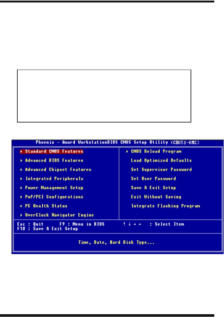
GeForce 6100 AM2 BIOS Setup
3
1.1 Main Menu
Once you enter Award BIOS™ CMOS Setup Utility, the Main Menu will appear
on the screen. The Main Menu allows you to select from several setup functions.
Use the arrow keys to select among the items and press <Enter> to accept and
enter the sub-menu.
Figure 1: Main Menu
!! WARNING !!
For better system performance, the BIOS firmware is being
continuously updated. The BIOS information described in this
manual (Figure 1, 2, 3, 4, 5, 6, 7, 8, 9) is for your reference
only. The actual BIOS information and settings on board may
be slightly different from this manual.

GeForce 6100 AM2 BIOS Setup
4
Standard CMOS Features
This submenu contains industry standard configurable options.
Advanced BIOS Features
This submenu allows you to configure advanced features of the BIOS.
Advanced Chipset Features
This submenu allows you to configure special chipset features.
Integrated Peripherals
This submenu allows you to configure certain IDE hard drive options and
Programmed Input/ Output features.
Power Management Setup
This submenu allows you to configure the power management features.
PnP/PCI Configurations
This submenu allows you to configure certain “Plug and Play” and PCI options.
PC Health Status
This submenu allows you to monitor the hardware of your system.
Frequency/ Voltage Control
This submenu allows you to change CPU Vcore Voltage and CPU/PCI clock.
(However, we suggest you to use the default setting. Changing the voltage and
clock improperly may damage the CPU or M/B!)
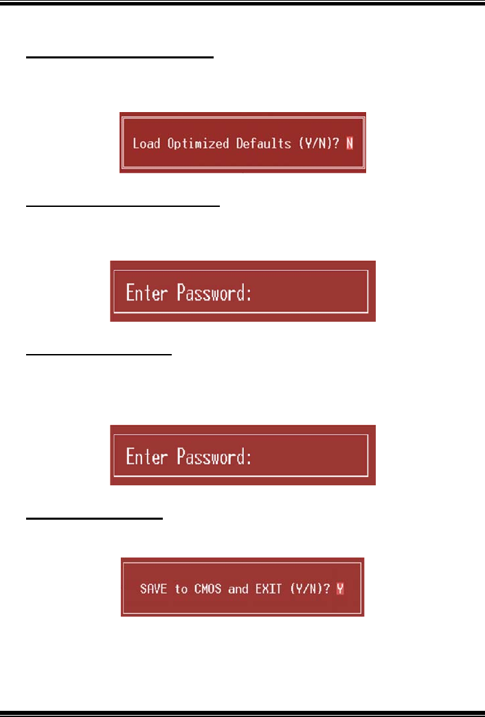
GeForce 6100 AM2 BIOS Setup
5
Load Optimized Defaults
This selection allows you to reload the BIOS when problem occurs during system
booting sequence. These configurations are factory settings optimized for this
system. A confirmation message will be displayed before defaults are set.
Set Supervisor Password
Setting the supervisor password will prohibit everyone except the supervisor from
making changes using the CMOS Setup Utility. You will be prompted with to
enter a password.
Set User Password
If the Supervisor Password is not set, then the User Password will function in the
same way as the Supervisor Password. If the Supervisor Password is set and the
User Password is set, the “User” will only be able to view configurations but will
not be able to change them.
Save & Exit Setup
Save all configuration changes to CMOS (memory) and exit setup. Confirmation
message will be displayed before proceeding.
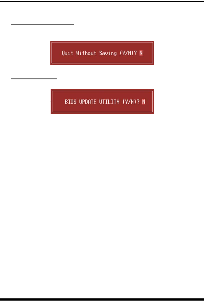
GeForce 6100 AM2 BIOS Setup
6
Exit Without Saving
Abandon all changes made during the current session and exit setup. Confirmation
message will be displayed before proceeding.
Upgrade BIOS
This submenu allows you to upgrade bios.
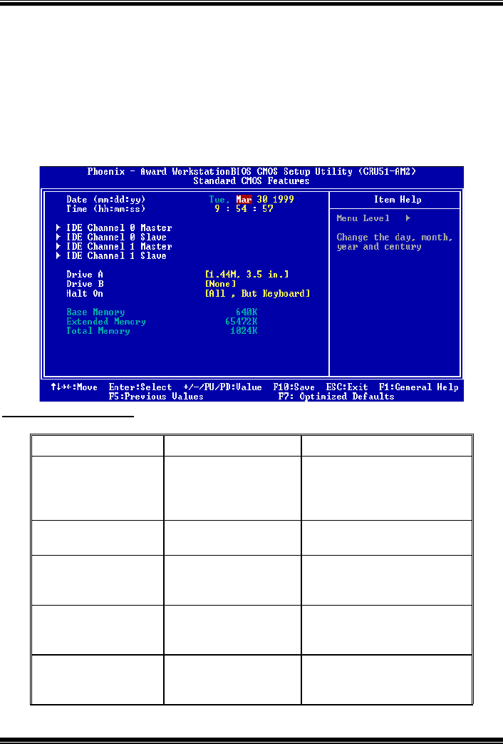
GeForce 6100 AM2 BIOS Setup
7
1.2 Standard CMOS Features
The items in Standard CMOS Setup Menu are divided into several categories.
Each category includes no, one or more than one setup items. Use the arrow keys
to highlight the item and then use the<PgUp> or <PgDn> keys to select the value
you want in each item.
Figure 2: Standard CMOS Setup
Main Menu Selections
This table shows the items and the available options on the Main Menu.
Item Options Description
Date mm : dd : yy
Set the system date. Note
that the ‘Day’ automatically
changes when you set the
date.
Time hh : mm : ss Set the system internal
clock.
IDE Primary Master Options are in its sub
menu.
Press <Enter> to enter the
sub menu of detailed
options
IDE Primary Slave Options are in its sub
menu.
Press <Enter> to enter the
sub menu of detailed
options.
IDE Secondary Master Options are in its sub
menu.
Press <Enter> to enter the
sub menu of detailed
options.

GeForce 6100 AM2 BIOS Setup
8
Item Options Description
IDE Secondary Slave Options are in its sub
menu.
Press <Enter> to enter the
sub menu of detailed
options.
Drive A
Drive B
360K, 5.25 in
1.2M, 5.25 in
720K, 3.5 in
1.44M, 3.5 in
2.88M, 3.5 in
None
Select the type of floppy
disk drive installed in your
system.
Video
EGA/VGA
CGA 40
CGA 80
MONO
Select the default video
device.
Halt On
All Errors
No Errors
All, but Keyboard
All, but Diskette
All, but Disk/ Key
Select the situation in which
you want the BIOS to stop
the POST process and
notify you.
Base Memory N/A
Displays the amount of
conventional memory
detected during boot up.
Extended Memory N/A
Displays the amount of
extended memory detected
during boot up.
Total Memory N/A Displays the total memory
available in the system.
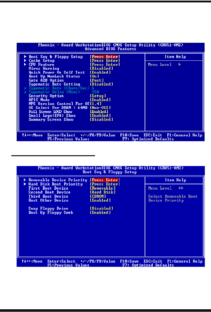
GeForce 6100 AM2 BIOS Setup
9
1.3 Advanced BIOS Features
Figure 3: Advanced BIOS Setup
Boot Seq & Floppy Setup
This item allows you to setup boot sequence & Floppy.
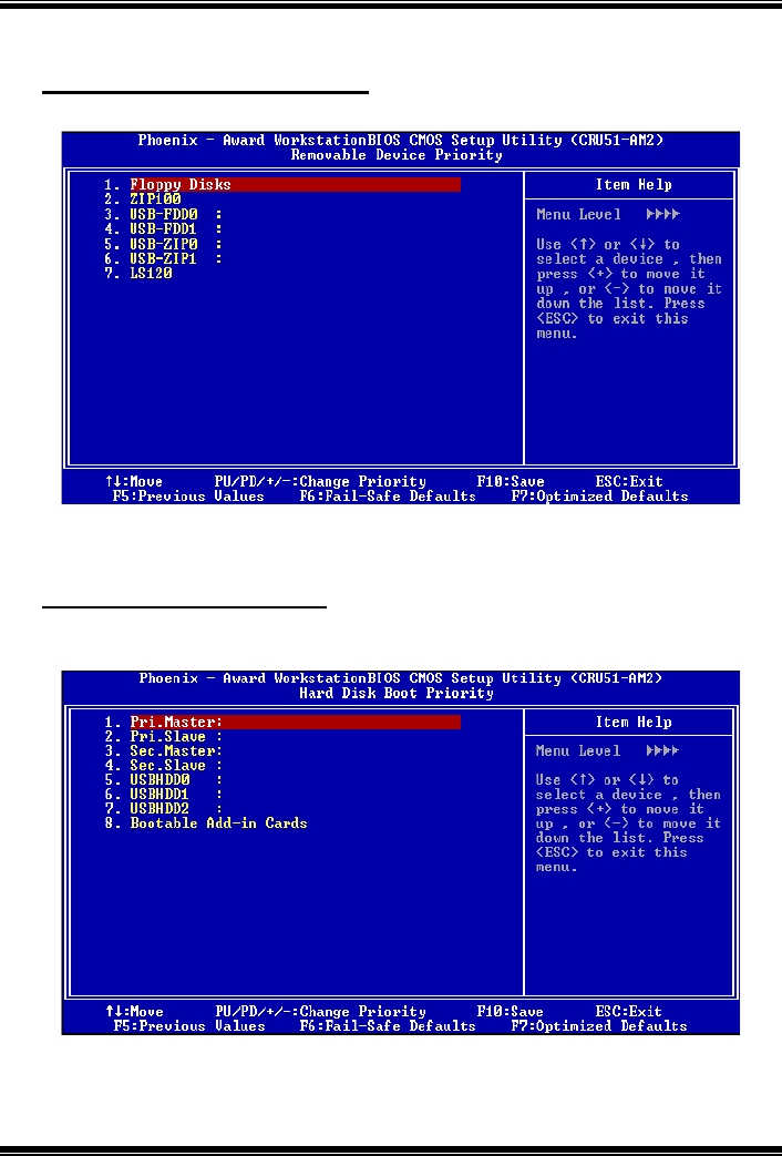
GeForce 6100 AM2 BIOS Setup
10
Removable Device Priority
Select Removable Boot Device Priority.
The Choices: Floppy Disks, Zip100, USB-FDD0, USB-FDD1, USB-ZIP0,
USB-ZIP1, LS120.
Hard Disk Boot Priority
The BIOS will attempt to arrange the Hard Disk boot sequence automatically.
You can change the Hard Disk booting sequence here.
The Choices: Pri. Master, Pri. Slave, Sec. Master, Sec. Slave, USB HDD0, USB
HDD1, USB HDD2, and Bootable Add-in Cards.
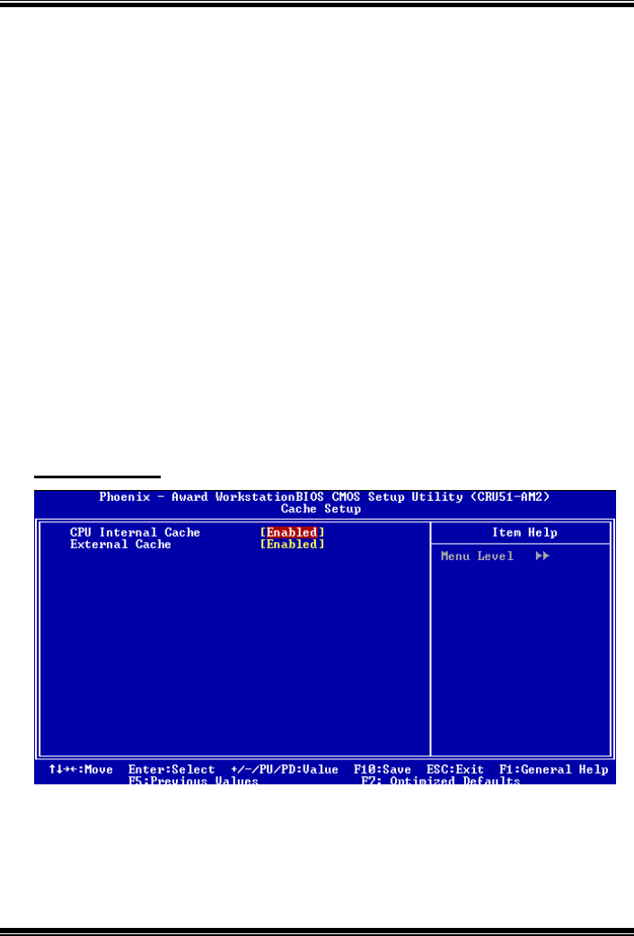
GeForce 6100 AM2 BIOS Setup
11
First/Second/Third Boot Device
The BIOS will attempt to load the operating system in this order.
The Choices: Floppy, LS120, HDD-0, SCSI, CDROM, HDD-1, HDD-2, HDD-3,
ZIP100, LAN, HPT370, Disabled.
Boot Other Device
When enabled, BIOS will try to load the operating system from other device when
it failed to load from the three devices above.
The Choices: Enabled (default), Disabled
Swap Floppy Drive
For systems with two floppy drives, this option allows you to swap logical drive
assignments.
The Choices: Disabled (default), Enabled.
Boot Up Floppy Seek
When enabled, System will test the floppy drives to determine if they have 40 or
80 tracks during boot up. Disabling this option reduces the time it takes to
boot-up.
The Choices: Enabled (default), Disabled.
Cache Setup
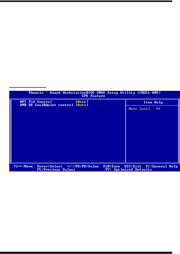
GeForce 6100 AM2 BIOS Setup
12
CPU Internal Cache
Depending on the CPU/chipset in use, you may be able to increase memory
access time with this option.
Enabled (default) Enable cache.
Disabled Disable cache.
External Cache
This option enables or disables “Level 2” secondary cache on the CPU, which
may improve performance.
Enabled (default) Enable cache.
Disabled Disable cache.
CPU Feature
NPT Fid Control
The Choices: Auto (default), x4 800, x5 1000, x6 1200, x7 1400, x8 1600, x9
1800, x10 2000.
AMD K8 Cool&Quiet control
The Choices: Auto (default).

GeForce 6100 AM2 BIOS Setup
13
Virus Warning
This option allows you to choose the VIRUS Warning feature that is used to
protect the IDE Hard Disk boot sector. If this function is enabled and an attempt is
made to write to the boot sector, BIOS will display a warning message on the
screen and sound an alarm beep.
Disabled (default) Virus protection is disabled.
Enabled Virus protection is activated.
Quick Power On Self Test
Enabling this option will cause an abridged version of the Power On Self-Test
(POST) to execute after you power up the computer.
Disabled Normal POST.
Enabled (default) Enable quick POST.
Boot Up NumLock Status
Selects the NumLock State after the system switched on.
The Choices:
On (default) Numpad is number keys.
Off Numpad is arrow keys.
Gate A20 Option
Select if chipset or keyboard controller should control Gate A20.
Normal A pin in the keyboard controller controls GateA20.
Fast (default) Lets chipset control Gate A20.
Typematic Rate Setting
When a key is held down, the keystroke will repeat at a rate determined by the
keyboard controller. When enabled, the typematic rate and typematic delay can be
configured.
The Choices: Disabled (default), Enabled.
Typematic Rate (Chars/Sec)
Sets the rate at which a keystroke is repeated when you hold the key down.
The Choices: 6 (default), 8, 10, 12, 15, 20, 24, 30.

GeForce 6100 AM2 BIOS Setup
14
Typematic Delay (Msec)
Sets the delay time after the key is held down before it begins to repeat the
keystroke.
The Choices: 250 (default), 500, 750, 1000.
Security Option
This option will enable only individuals with passwords to bring the system online
and/or to use the CMOS Setup Utility.
System: A password is required for the system to boot and is also
required to access the Setup Utility.
Setup (default): A password is required to access the Setup Utility only.
This will only apply if passwords are set from the Setup main menu.
APIC MODE
Selecting Enabled enables APIC device mode reporting from the BIOS to the
operating system.
The Choices: Enabled (default), Disabled.
MPS Version Control For OS
The BIOS supports version 1.1 and 1.4 of the Intel multiprocessor specification.
Select version supported by the operation system running on this computer.
The Choices: 1.4 (default), 1.1.
OS Select For DRAM > 64MB
A choice other than Non-OS2 is only used for OS2 systems with memory
exceeding 64MB.
The Choices: Non-OS2 (default), OS2.
Small Logo(EPA) Show
This item allows you to select whether the “Small Logo” shows. Enabled (default)
“Small Logo” shows when system boots up. Disabled No “Small Logo” shows
when system boots
The Choices: Enabled (default), Disabled

GeForce 6100 AM2 BIOS Setup
15
Summary Screen Show
This item allows you to enable/disable the summary screen. Summary screen
means system configuration and PCI device listing.
The Choices: Disabled (default), Enabled.

GeForce 6100 AM2 BIOS Setup
16
1.4 Advanced Chipset Features
This submenu allows you to configure the specific features of the chipset installed
on your system. This chipset manage bus speeds and access to system memory
resources, such as DRAM. It also coordinates communications with the PCI bus.
The default settings that came with your system have been optimized and therefore
should not be changed unless you are suspicious that the settings have been
changed incorrectly.
Figure 4. Advanced Chipset Setup
Frame Buffer Size
The Choices: 32M (default), 16M, 64M, 128M, Disabled.
PMU
The Choices: Auto (default), Disabled.
NB-->SB HT Speed
The Choices: 4X (default).1X, 2X, 3X, 5X.
NB<--SB HT Speed
The Choices: 4X (default).1X, 2X, 3X, 5X.

GeForce 6100 AM2 BIOS Setup
17
K8<->NB HT Width
The Choices:↓16 ↑16 (default), ↓8 ↑8.
NB<->SB HT Width
The Choices: ↓8 ↑8 (default), ↓16 ↑16.
Err94 Enh
This item allows you to enable/disable the “sequential Prufetch Feature” of K8
CPU.
The Choices: Auto (default), Disabled.
Onboard GPU
The Choices: Auto (default), Always Enable.
CPU Spread Spectrum
The Choices: Disabled (default), Center, Down.
PCIE Spread Spectrum
This item allows you to disable \ enable the SATA spread spectrum function.
The Choices: Disabled (default), Enabled.
SATA Spread Spectrum
This item allows you to disable \ enable the SATA spread spectrum function.
The Choices: Disabled (default), Enabled.
HT Spread Spectrum
The Choices: Disabled (default), Center, Down.
SSE/SSE2 Instructions
The Choices: Enabled (default), Disabled.

GeForce 6100 AM2 BIOS Setup
18
System BIOS Cacheable
Selecting the “Disabled ” option allows caching of the system BIOS ROM at
F0000h-FFFFFh which can improve system performance. However, any programs
writing to this area of memory will cause conflicts and result in system errors.
The Choices: Disabled (default), Enabled.
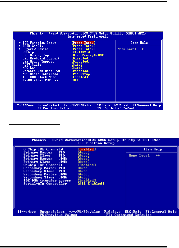
GeForce 6100 AM2 BIOS Setup
19
1.5 Integrated Peripherals
Figure 5. Integrated Peripherals
IDE Function Setup
Highlight the “Press Enter” label next to the “VIA OnChip IDE Device” label and
press enter key will take you a submenu with the following options:

GeForce 6100 AM2 BIOS Setup
20
On-chip IDE Channel 0/1
The motherboard chipset contains a PCI IDE interface with support for two IDE
channels. Select “Enabled” to activate the first and/or second IDE interface.
Select “Disabled” to deactivate an interface if you are going to install a primary
and/or secondary add-in IDE interface.
The Choices: Enabled (default), Disabled.
IDE Primary/Secondary/Master/Slave PIO
The IDE PIO (Programmed Input / Output) fields let you set a PIO mode (0-4) for
each of the IDE devices that the onboard IDE interface supports. Modes 0 to 4
will increase performance progressively. In Auto mode, the system automatically
determines the best mode for each device.
The Choices: Auto (default), Mode0, Mode1, Mode2, Mode3, Mode4.
IDE Primary/Secondary/Master/Slave UDMA
Ultra DMA function can be implemented if it is supported by the IDE hard drives
in your system. As well, your operating environment requires a DMA driver
(Windows 95 or OSR2may need a third party IDE bus master driver). If your hard
drive and your system software both support Ultra DMA, select Auto to enable
BIOS support.
The Choices: Auto (default), Disabled.
IDE DMA Transfer Access
This item allows you to enable or disable the IDE DMA transfer access.
The Choices: Enabled (default), Disabled.
Serial-ATA Controller
The Choices: All Enabled (default).
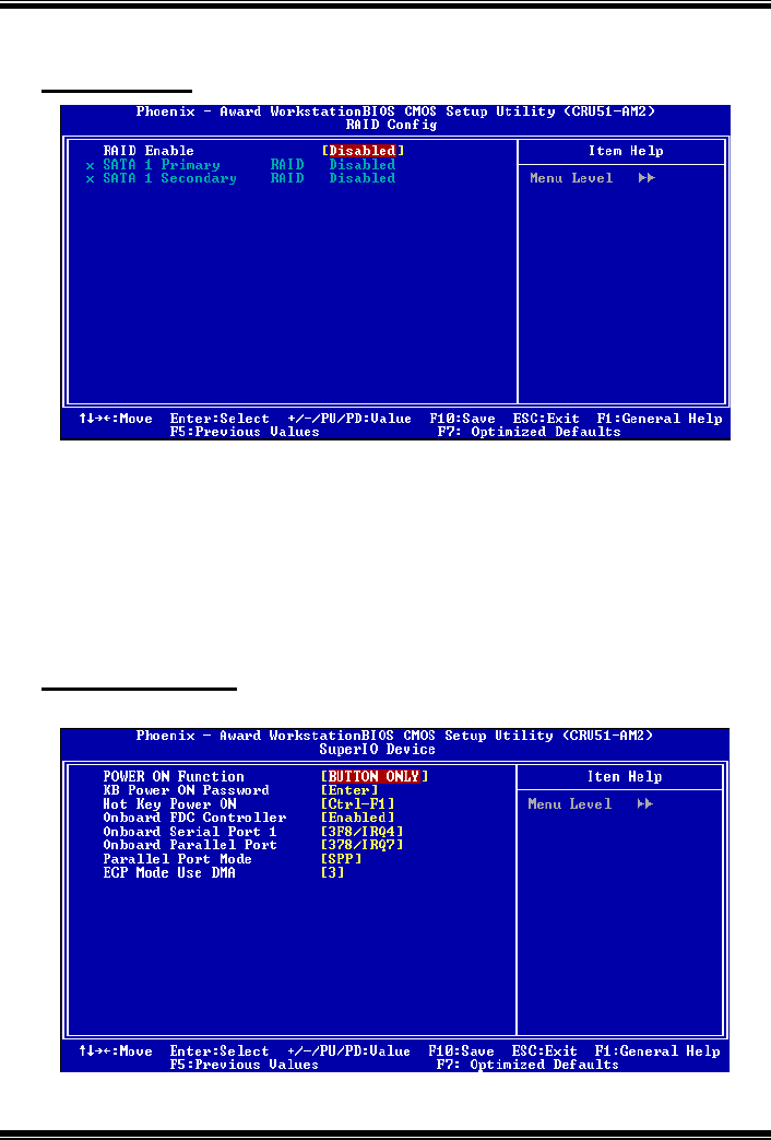
GeForce 6100 AM2 BIOS Setup
21
RAID Config
RAID Enable
This option allows you to enable or disable RAID function.
The Choices: Disabled (default), Enabled.
SATA 1/2 Primary/Secondary RAID
This option allows you to enable or disable SATA A Primary/Secondary RAID.
The Choices: Disabled (default), Enabled.
Super IO Device
Press Enter to configure the Super I/O Device.

GeForce 6100 AM2 BIOS Setup
22
Power On Function
This item allows you to choose the power on method.
The Choices: Button Only (default), Password, Hot Key, Mouse Left, Mouse
Right, Any Key, Keyboard 98.
KB Power on Password
Input password and press Enter to set the Keyboard power on password.
HOT Key power ON
Choose the Hot Key combination to boot up the system.
The Choices: Ctrl-F1 (default), Ctrl-F2, Ctrl-F3, Ctrl-F4, Ctrl-F5, Ctrl-F6,
Ctrl-F7, Ctrl-F8, Ctrl-F9, Ctrl-F10, Ctrl-F11, Ctrl-F12.
Onboard FDC Controller
Select enabled if your system has a floppy disk controller (FDC) installed on the
system board and you wish to use it. If you installed another FDC or the system
uses no floppy drive, select disabled in this field.
The Choices: Enabled (default), Disabled.
Onboard Serial Port 1
Select an address and corresponding interrupt for the first and second serial ports.
The Choices: 3F8/IRQ4 (default), Disabled, 2F8/IRQ3, 3E8/IRQ4, 2E8/IRQ3,
Auto.
Onboard Parallel Port
This item allows you to determine access onboard parallel port controller with
which I/O Address.
The Choices: 378/IRQ7 (default), 278/IRQ5, 3BC/IRQ7, Disabled.
Parallel Port Mode
This item allows you to determine how the parallel port should function. The
default value is SPP.
The Choices:
SPP (default) Using Parallel port as Standard Printer Port.
EPP Using Parallel Port as Enhanced Parallel Port.
ECP Using Parallel port as Extended Capabilities Port.
ECP+EPP Using Parallel port as ECP & EPP mode.
ECP Mode Use DMA
Select a DMA Channel for the port.
The Choices: 3 (default), 1.

GeForce 6100 AM2 BIOS Setup
23
OnChip USB
This option should be enabled if your system has a USB installed on the system
board. You may need to disable this feature if you add a higher performance
controller.
The Choices: V1.1+V2.0 (default), Disabled, V1.1
USB Memory Type
The Choices: Base Memory<640k>(default).
USB Keyboard Support
This item allows you to enable or disable the USB Keyboard Legacy Support.
Enabled Enable USB Keyboard Support.
Disabled (default) Disable USB Keyboard Support.
USB Mouse Support
This item allows you to enable or disable the USB Mouse Legacy Support.
Enabled Enable USB Mouse Support.
Disabled (default) Disable USB Mouse Support.
AC97 Audio
This item allows you to enable or disable to support AC97 Audio.
The Choices: Auto (default), Disabled.
MAC LAN
This option allows you to control the onboard MAC LAN.
The Choices: Auto (default), Disabled.
Onboard LAN Boot ROM
This item allows you to enable or disable the Onboard LAN Boot ROM.
The Choices: Disabled (default), Enabled.

GeForce 6100 AM2 BIOS Setup
24
MAC Media Interface
This option allows you to control the onboard MAC Media Interface.
The Choices: Pin Strap (default), Disabled
IDE HDD Block Mode
Block mode is also called block transfer, multiple commands, or multiple sectors
read / write. If your IDE hard drive supports block mode (most new drives do),
select Enabled for automatic detection of the optimal number of block mode (most
new drives do), select Enabled for automatic detection of the optimal number of
block read / write per sector where the drive can support.
The Choices: Enabled (default), Disabled.
POWER After PWR-Fail
This setting specifies how your system should behave after a power fail or
interrupts occurs. By choosing off will leave the computer in the power off state.
Choosing On will reboot the computer. Former-Sts will restore the system to the
status before power failure or interrupt occurs.
The Choices: Off (default), On, Former-Sts.
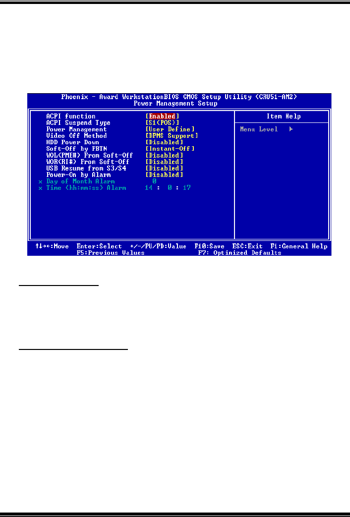
GeForce 6100 AM2 BIOS Setup
25
1.6 Power Management Setup
The Power Management Setup Menu allows you to configure your system to
utilize energy conservation and power up/power down features.
Figure 6. Power Management Setup
ACPI Function
This item displays the status of the Advanced Configuration and Power
Management (ACPI).
The Choices: Enabled (default), Disabled.
ACPI Suspend Type
The item allows you to select the suspend type under the ACPI operating system.
The Choices: S1 (POS) (default) Power on Suspend
S3 (STR) Suspend to RAM
S1 & S3 POS+STR

GeForce 6100 AM2 BIOS Setup
26
Power Management
This category allows you to select the power saving method and is directly related
to the following modes:
1. HDD Power Down.
2. Suspend Mode.
There are three options of Power Management, three of which have fixed mode
settings
Min. Power Saving
Minimum power management.
Suspend Mode = 1 hr.
HDD Power Down = 15 min
Max. Power Saving
Maximum power management only available for sl CPU’s.
Suspend Mode = 1 min.
HDD Power Down = 1 min.
User Define (default)
Allow you to set each option individually.
When you choose user define, you can adjust each of the item from 1 min. to 1 hr.
except for HDD Power Down which ranges from 1 min. to 15 min.
Video Off Method
This option determines the manner when the monitor goes blank.
V/H SYNC+Blank
This selection will cause the system to turn off the vertical and horizontal
synchronization ports and write blanks to the video buffer.
Blank Screen
This option only writes blanks to the video buffer.
DPMS(default)
Initial display power management signaling.
HDD Power Down
When enabled, the hard-disk drives will power down after a set time of system
inactivity. All other devices remain active.
The Choices: Disabled (default), 1 Min, 2 Min, 3 Min, 4 Min, 5 Min, 6 Min, 7
Min, 8 Min, 9 Min, 10 Min, 11 Min, 12 Min, 13 Min, 14 Min, 15Min.

GeForce 6100 AM2 BIOS Setup
27
Soft-Off by PWR-BTN
This item determines the behavior of system power button. Instant off turn off the
power immediately, and Delay 4 Sec. will require you to press and hold the power
button for 4 seconds to cut off the system power.
The Choices: Delay 4 Sec, Instant-Off (default).
WOL(PME#)/ From Soft-Off
This item allows you to enable or disable Wake On LAN from Soft-Off function.
The Choices: Disabled (default), Enabled.
WOR(RI#) From Soft-Off
This item allows you to enable or disable Wake On Ring from Soft-Off function.
The Choices: Disabled (default), Enabled.
USB Resume from S3/S4
This item allows you to wake up from S3 with USB device.
The Choices: Disabled (default), Enabled.
Power-On by Alarm
This function is for setting date and time for your computer to boot up. When
enabled, you can choose the date and time to boot up the system.
The Choices: Disabled (default), Enabled.
Date (of Month) Alarm
You can choose which month the system will boot up.
Time (hh:mm:ss) Alarm
You can choose the system boot up time, input hour, minute and second to specify.
Note: If you have change the setting, you must let the system boot up until it
goes to the operating system, before this function will work.
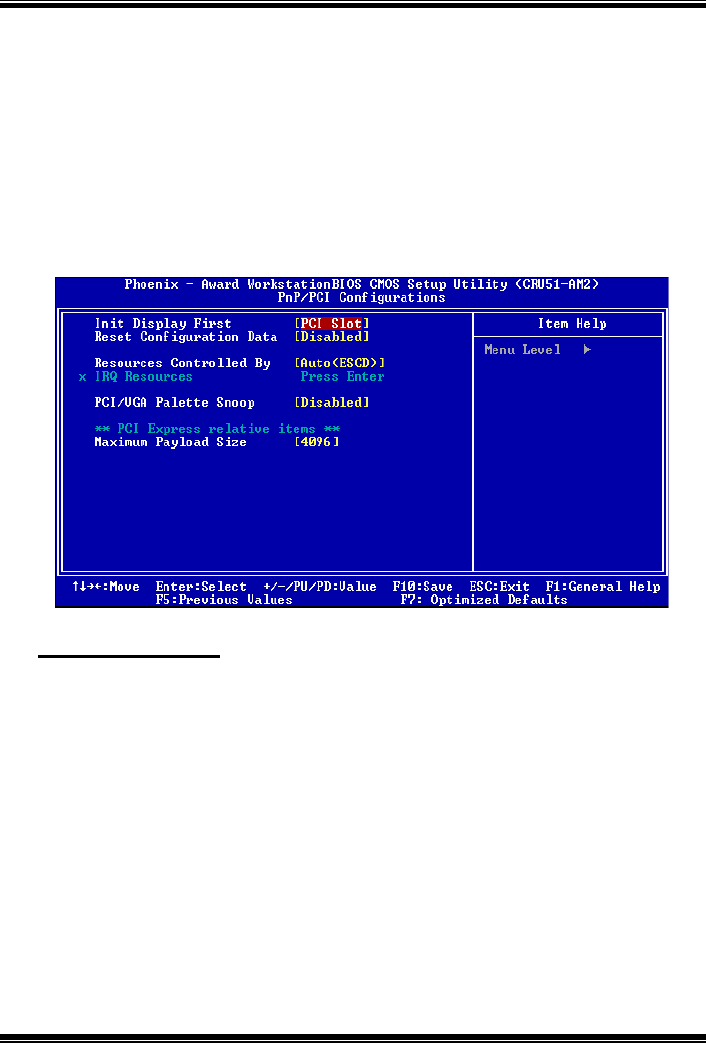
GeForce 6100 AM2 BIOS Setup
28
1.7 PnP/PCI Configurations
This section describes configuring the PCI bus system. PCI, or Personal Computer
Interconnect, is a system which allows I/O devices to operate at speeds nearing the
speed of the CPU itself uses when communicating with its own special
components. This section covers some very technical items and it is strongly
recommended that only experienced users should make any changes to the default
settings.
Figure 7: PnP/PCI Configurations
Init Display First
This item allows you to decide to active whether PCI Slot or on-chip VGA first.
The Choices: PCEx, PCI Slot (default).

GeForce 6100 AM2 BIOS Setup
29
Reset Configuration Data
The system BIOS supports the PnP feature which requires the system to record
which resources are assigned and protects resources from conflict.
Every peripheral device has a node, which is called ESCD. This node records
which resources are assigned to it. The system needs to record and update ESCD
to the memory locations. These locations are reserved in the system BIOS. If the
Disabled (default) option is chosen, the system‘s ESCD will update only when the
new configuration varies from the last one. If the Enabled option is chosen, the
system is forced to update ESCDs and then is automatically set to the “Disabled”
mode.
The above settings will be shown on the screen only if “Manual” is chosen for the
resources controlled by function.
Legacy is the term, which signifies that a resource is assigned to the ISA Bus and
provides non-PnP ISA add-on cards. PCI / ISA PnP signify that a resource is
assigned to the PCI Bus or provides for ISA PnP add-on cards and peripherals.
The Choices: Disabled (default), Enabled.
Resources Controlled By
By Choosing “Auto(ESCD)” (default), the system BIOS will detect the system
resources and automatically assign the relative IRQ and DMA channel for each
peripheral. By Choosing “Manual”, the user will need to assign IRQ & DMA for
add-on cards. Be sure that there are no IRQ/DMA and I/O port conflicts.
The Choices: Auto (ESCD) (default), Manual.

GeForce 6100 AM2 BIOS Setup
30
IRQ Resources
This submenu will allow you to assign each system interrupt a type, depending on
the type of device using the interrupt. When you press the “Press Enter” tag, you
will be directed to a submenu that will allow you to configure the system interrupts.
This is only configurable when “Resources Controlled By” is set to “Manual”.
IRQ-3 assigned to PCI Device
IRQ-4 assigned to PCI Device
IRQ-5 assigned to PCI Device
IRQ-7 assigned to PCI Device
IRQ-9 assigned to PCI Device
IRQ-10 assigned to PCI Device
IRQ-11 assigned to PCI Device
IRQ-12 assigned to PCI Device
IRQ-14 assigned to PCI Device
IRQ-15 assigned to PCI Device
PCI / VGA Palette Snoop
Some old graphic controllers need to “snoop” on the VGA palette and then map it
to their display as a way to provide boot information and VGA compatibility. This
item allows such snooping to take place.
The Choices: Disabled (default), Enabled
Maximum Payload Size
Set the maximum payload size for Transaction packets (TLP).
The Choice: 4096 (default.), 128, 256, 512, 1024, 2048.
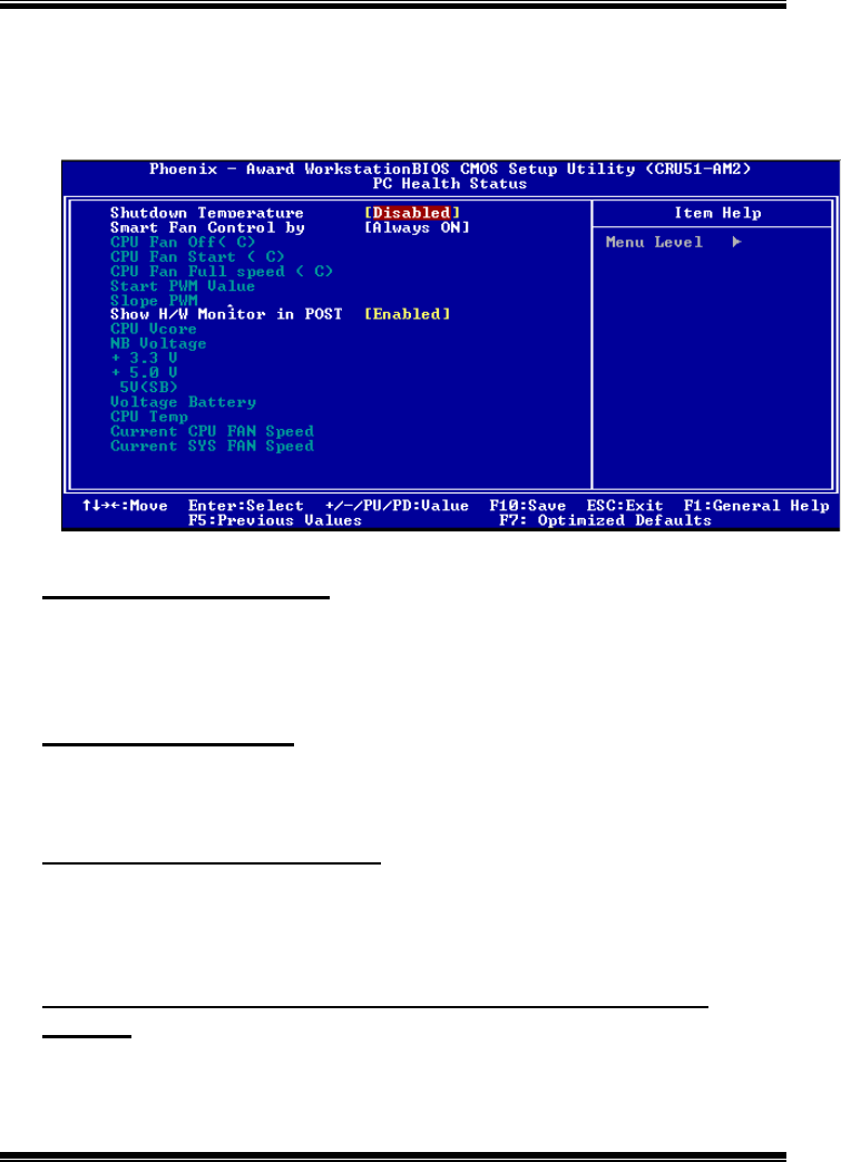
GeForce 6100 AM2 BIOS Setup
31
1.8 PC Health Status
Figure 8: PC Health Status
Shutdown Temperature
This item allows you to set up the CPU shutdown Temperature. This item is only
effective under Windows 98 ACPI mode.
The Choices: Disabled (default) , 70℃/ 158℉, 75℃/ 167℉, 80℃/ 176℉.
CPU FAN Control by
The Choice “smart” can make your CPU FAN to reduce noise.
The Choices: SMART, Always On (default).
Show H/W Monitor in POST
If you computer contains a monitoring system, it will show PC health status during
POST stage. The item offers several different delay times.
The Choices: Enabled (default), Disabled.
CPU Vcore, NB Voltage, +3.3V, +5.0V, 5V (SB), Voltage
Battery
Detect the system’s voltage status automatically.
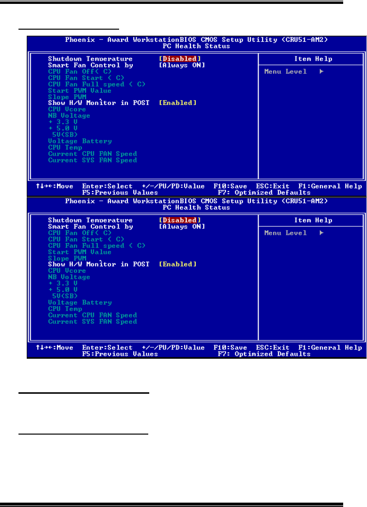
GeForce 6100 AM2 BIOS Setup
32
Current CPU Temp
This field displays the current temperature of CPU.
Current CPU FAN Speed
This field displays the current speed of CPU fan.
Current SYS FAN Speed
This field displays the current speed SYSTEM fan.
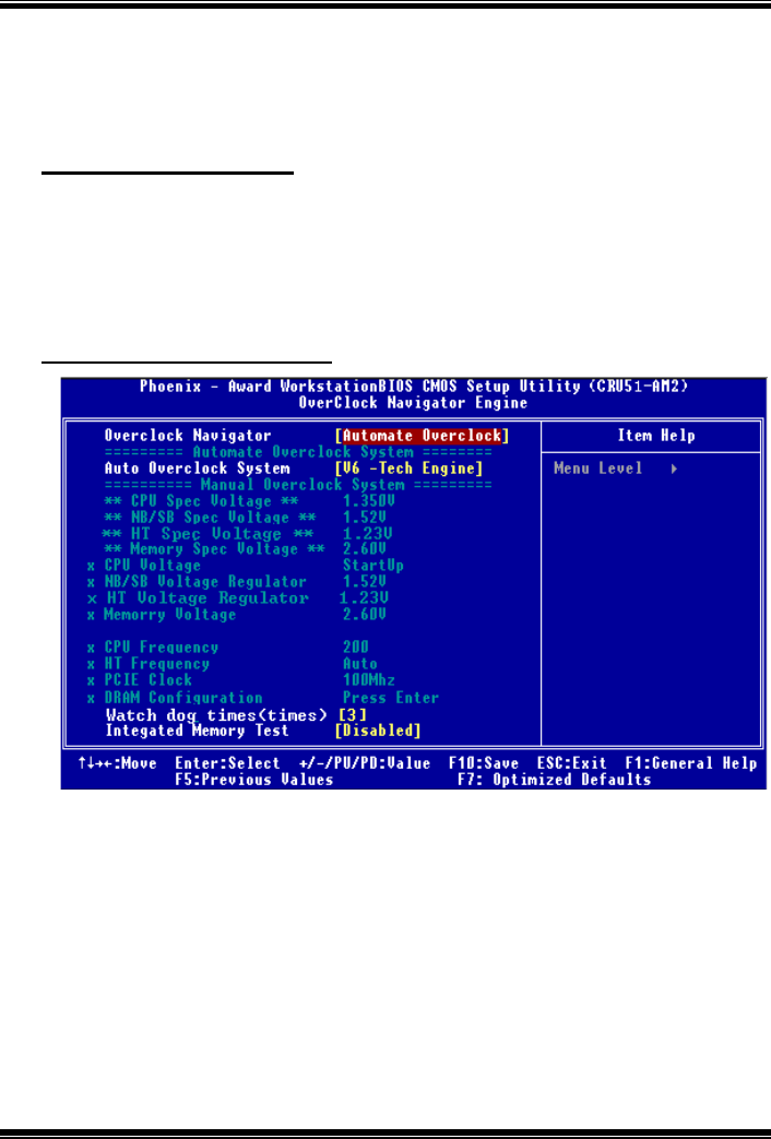
GeForce 6100 AM2 BIOS Setup
33
1.9 Over Clock Navigator Engine
OverClock Navigator
OverClock .Navigator is designed for beginners in overclock field.
Based on many test and experiments from Biostar Engineer Team, OverClock
Navigator provides 3 default overclock configurations that are able to raise the
system performance
The Choices: Normal (default), Automate Overclock, Manual Overclock
Auto OverClock System
The Overclock Navigator provides 3 different engines helping you to overclock
your system. These engines will boost your system performance to different level.
The Choices:
V6 Tech Engine
This setting will raise about 5%~10% of whole system performance.
V8 Tech Engine
This setting will raise about 15%~25% of whole system performance.
V12 Tech Engine
This setting will raise about 25%~30% of whole system performance.
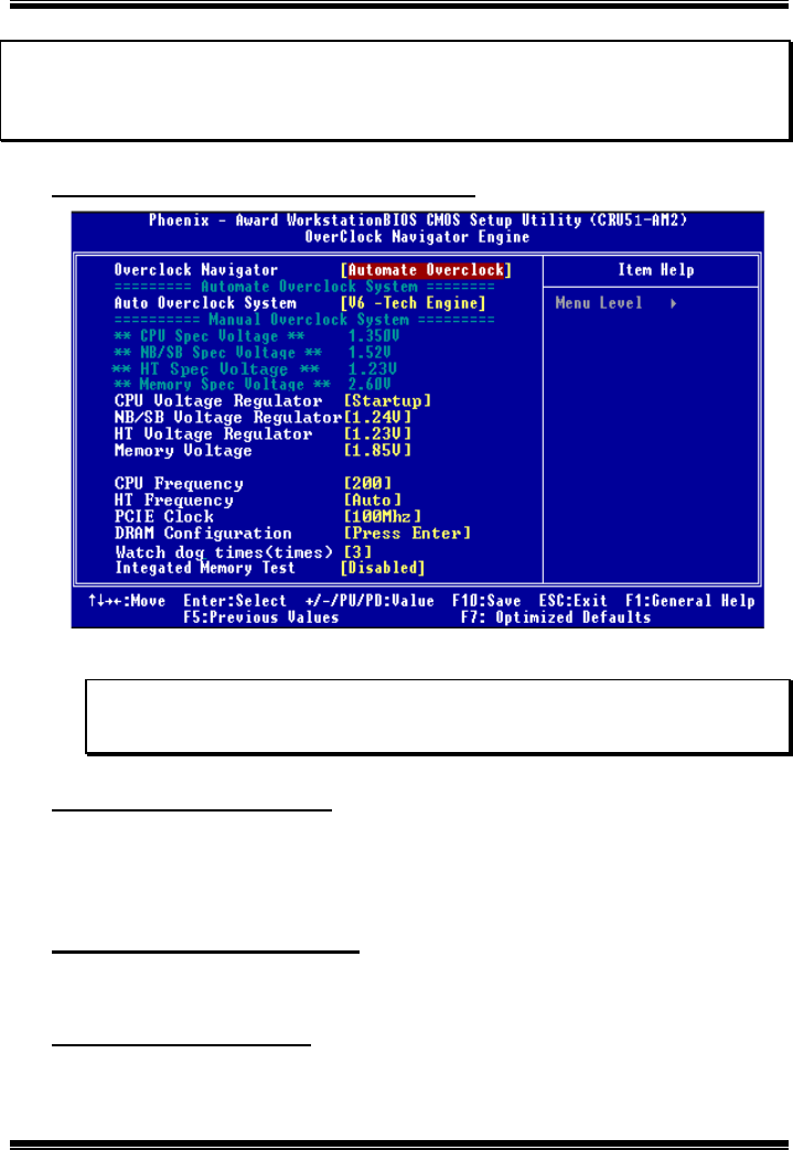
GeForce 6100 AM2 BIOS Setup
34
Cautions:
1. Not every AMD CPU performs the above overclock setting ideally; the difference may vary
with the installed CPU model.
2. From BET experiment, the Atholon64 FX CPU is not suitable for this A.O.S. feature.
Manual Overclock System (M.O.S.)
MOS is designed for experienced overclock users.
It allows users to customize personal overclock setting.
Note:
Based on our test results; the overclock function achieved the best performance on AMD
3000+ CPU
CPU Voltage Reguqltor
This item allows you to select CPU Voltage Control.
The Choices: StartUp (default), 1.725V, 1.700V, 1.675V, 1.650V, 1.625V,
1.600V etc.
NB/SB Voltage Ragurator
The Choices: 1.24V (default).1.27V, 1.32V, 1.36V
HT Voltage Regulator
The Choices: 1.23V (default).1.25V, 130V, 1.35V.
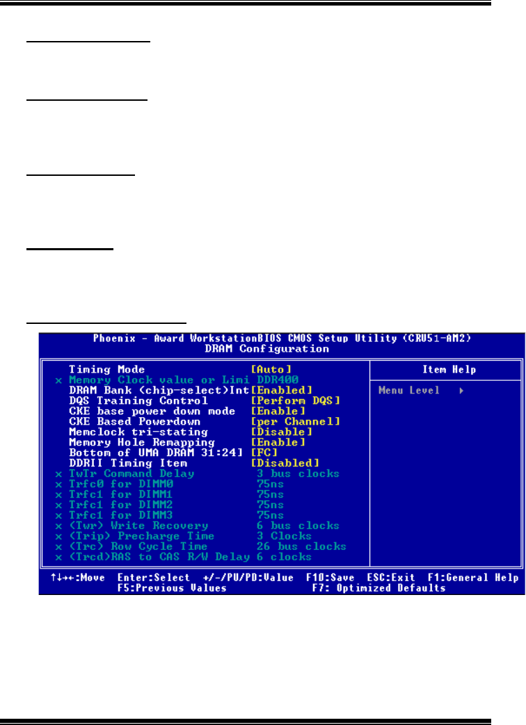
GeForce 6100 AM2 BIOS Setup
35
Memory Voltage
The Choices: 1.85V (default).1.90V, 1.95V, 2.00V
CPU Frequency
This item allows you to select the CPU Frequency.
The Choices: 200 to 450 with an interval of 1. (Default value is 200)
HT Frequency
This item allows you to select the HT Frequency.
The Choices: 4x (default),1x,2x,3x,5x.Auto,x4.
PCIE Clock
The Choices: 100MHz (default), 101MHz, 102MHz, 103MHz, 104MHz,
105MHz, 106MHz, 107MHz, etc.
DRAM Configuration
Timing Mode
The Choices: Auto (Default), Manual.
DRAM Bank (chip-select)Int
The Choices: Enable (Default), Disable.

GeForce 6100 AM2 BIOS Setup
36
DQS Training Control
The Choices: Perform DQS (Default), Skip DQS
CKE base power down mode
The Choices: Enable (Default), Disable.
CKE base power down
The Choices: per Channel (Default)., Per CS.
Memclock tri-stating
The Choices: Disable (Default), Enable.
Memory Hole Remapping
The Choices: Enable (Default), Disable.
Bottom of UMA DRAM 31:24
The Choices: FC (Default), key in a HEX number between 0000~ 00FC
DDRII Timing Item
The Choices: Disable (Default), Enable.
Twtr Command Delay
The Choices: 3 bus Clocks (Default), 1 bus Clock, 2 bus clocks.
Trfc0 for DIMM0
The Choices: 75ns (Default), 105ns, 127.5ns, 195ns, 327.5ns.
Trfc0 for DIMM1
The Choices: 75ns (Default), 105ns, 127.5ns, 195ns, 327.5ns.
Trfc0 for DIMM2
The Choices: 75ns (Default), 105ns, 127.5ns, 195ns, 327.5ns.
Trfc0 for DIMM3
The Choices: 75ns (Default), 105ns, 127.5ns, 195ns, 327.5ns.
(Twr) Write Recovery
The Choices: 6 bus Clocks(Default), 3 bus Clocks, 4 bus clocks, 5 bus clocks..
(Trip) Precharge Time
The Choices: 3 Clocks(Default), 2 Clock.
(Trc) Row Cycle Time
The Choices: 26 bus Clocks(Default), 11~26 bus Clocks..

GeForce 6100 AM2 BIOS Setup
37
(Trcd) RAS to CAS R/W Delay
The Choices: 6 Clocks(Default), 3 Clocks, 4 clocks, 5 clocks..
(Trrd) RAS to RAS Delay
The Choices: 5 Clocks(Default), 2 Clocks, 3 clocks, 4 clocks..
(Trp) Row Precharge Time
The Choices: 6 Clocks(Default), 3 Clocks, 4clocks, 5clocks..
(Tras)Minimum RAS Active T
The Choices: 18 bus Clocks(Default), 5~18 bus Clocks..
Watch dog time(times)
The Choices: 3 (default).
Integrated Memory Test
Integrated Memory Test allows users to test memory module compatibilities
without additional device or software.
Step 1:
This item is disabled on default; change it to “Enable” to precede memory test.
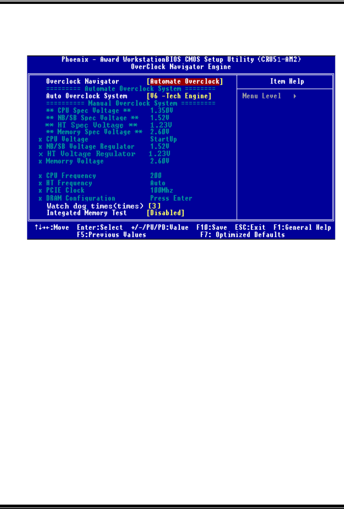
GeForce 6100 AM2 BIOS Setup
38
Step 2:
When the process is done, change the setting back from “Enabled” to “Disabled”
to complete the test.
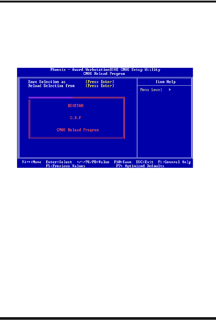
GeForce 6100 AM2 BIOS Setup
39
1.10 CMOS Reload Program(C.R.P.)
The CMOS Reload Program (CRP) allows you to save different CMOS settings
into BIOS-ROM. You may reload any saved CMOS setting to change system
configurations. Moreover, you may save your ideal overclock setting for easier
overclocking. There are 50 sets record addresses in total, and you may name the
saved CMOS data individually.

GeForce 6100 AM2 BIOS Setup
40
2 BIOS Setup (Ver 1.x)
Introduction
The purpose of this manual is to describe the settings in the Award™ BIOS Setup
program on this motherboard. The Setup program allows users to modify the basic
system configuration and save these settings to CMOS RAM. The power of
CMOS RAM is supplied by a battery so that it retains the Setup information when
the power is turned off.
Basic Input-Output System (BIOS) determines what a computer can do without
accessing programs from a disk. This system controls most of the input and output
devices such as keyboard, mouse, serial ports and disk drives. BIOS activates at
the first stage of the booting process, loading and executing the operating system.
Some additional features, such as virus and password protection or chipset
fine-tuning options are also included in BIOS.
The rest of this manual will to guide you through the options and settings in BIOS
Setup.
Plug and Play Support
This AWARD BIOS supports the Plug and Play Version 1.0A specification and
ESCD (Extended System Configuration Data) write.
EPA Green PC Support
This AWARD BIOS supports Version 1.03 of the EPA Green PC specification.
APM Support
This AWARD BIOS supports Version 1.1&1.2 of the Advanced Power
Management (APM) specification. Power management features are implemented
via the System Management Interrupt (SMI). Sleep and Suspend power
management modes are supported. Power to the hard disk drives and video
monitors can also be managed by this AWARD BIOS.
ACPI Support
Award ACPI BIOS support Version 1.0 of Advanced Configuration and Power
interface specification (ACPI). It provides ASL code for power management and
device configuration capabilities as defined in the ACPI specification, developed
by Microsoft, Intel and Toshiba.

GeForce 6100 AM2 BIOS Setup
41
PCI Bus Support
This AWARD BIOS also supports Version 2.1 of the Intel PCI (Peripheral
Component Interconnect) local bus specification.
DRAM Support
DDR SDRAM (Double Data Rate Synchronous DRAM) is supported.
Supported CPUs
This AWARD BIOS supports the AM2 CPU.
Using Setup
Use the arrow keys to highlight items in most of the place, press <Enter> to select,
use the <PgUp> and <PgDn> keys to change entries, press <F1> for help and press
<Esc> to quit. The following table provides more detail about how to navigate in
the Setup program by using the keyboard.
Keystroke Function
Up arrow Move to previous item
Down arrow Move to next item
Left arrow Move to the item on the left (menu bar)
Right arrow Move to the item on the right (menu bar)
Move Enter Move to the item you desired
PgUp key Increase the numeric value or make changes
PgDn key Decrease the numeric value or make changes
+ Key Increase the numeric value or make changes
- Key Decrease the numeric value or make changes
Esc key Main Menu – Quit and not save changes into CMOS
Status Page Setup Menu and Option Page Setup Menu – Exit
Current page and return to Main Menu
F1 key General help on Setup navigation keys
F5 key Load previous values from CMOS
F7 key Load the optimized defaults
F10 key Save all the CMOS changes and exit
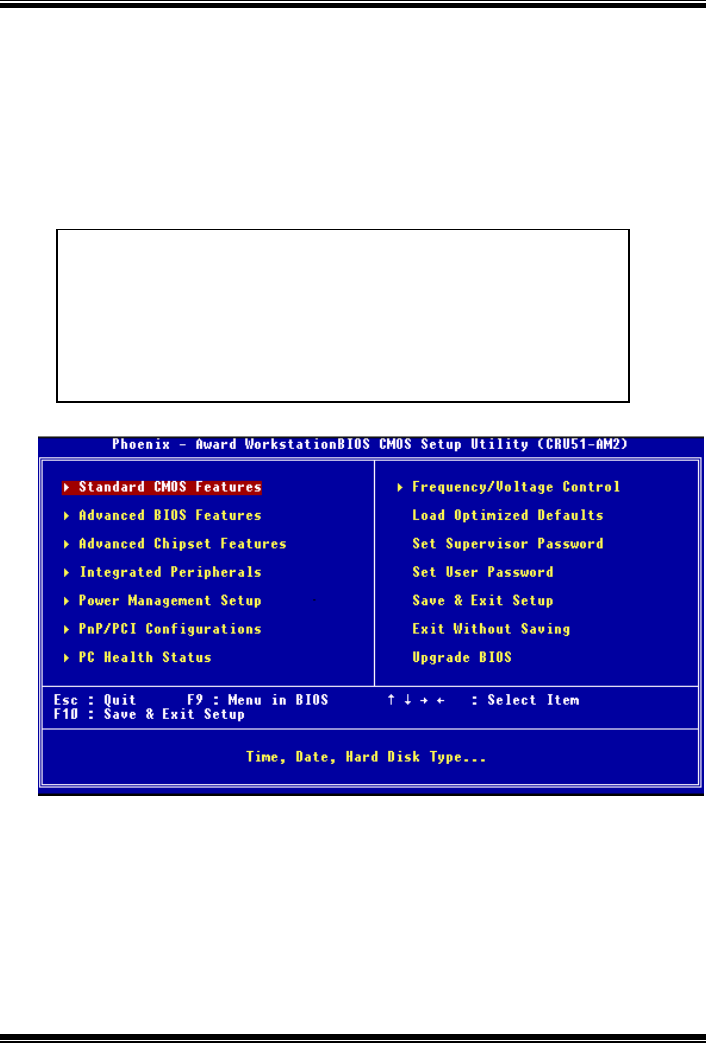
GeForce 6100 AM2 BIOS Setup
42
2.1 Main Menu
Once you enter Award BIOS™ CMOS Setup Utility, the Main Menu will appear
on the screen. The Main Menu allows you to select from several setup functions.
Use the arrow keys to select among the items and press <Enter> to accept and
enter the sub-menu.
Figure 1: Main Menu
!! WARNING !!
For better system performance, the BIOS firmware is being
continuously updated. The BIOS information described in this
manual (Figure 1, 2, 3, 4, 5, 6, 7, 8, 9) is for your reference
only. The actual BIOS information and settings on board may
be slightly different from this manual.

GeForce 6100 AM2 BIOS Setup
43
Standard CMOS Features
This submenu contains industry standard configurable options.
Advanced BIOS Features
This submenu allows you to configure advanced features of the BIOS.
Advanced Chipset Features
This submenu allows you to configure special chipset features.
Integrated Peripherals
This submenu allows you to configure certain IDE hard drive options and
Programmed Input/ Output features.
Power Management Setup
This submenu allows you to configure the power management features.
PnP/PCI Configurations
This submenu allows you to configure certain “Plug and Play” and PCI options.
PC Health Status
This submenu allows you to monitor the hardware of your system.
Frequency/ Voltage Control
This submenu allows you to change CPU Vcore Voltage and CPU/PCI clock.
(However, we suggest you to use the default setting. Changing the voltage and
clock improperly may damage the CPU or M/B!)
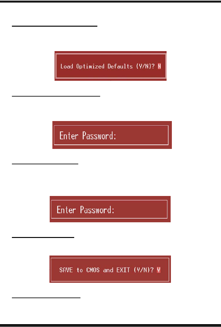
GeForce 6100 AM2 BIOS Setup
44
Load Optimized Defaults
This selection allows you to reload the BIOS when problem occurs during system
booting sequence. These configurations are factory settings optimized for this
system. A confirmation message will be displayed before defaults are set.
Set Supervisor Password
Setting the supervisor password will prohibit everyone except the supervisor from
making changes using the CMOS Setup Utility. You will be prompted with to
enter a password.
Set User Password
If the Supervisor Password is not set, then the User Password will function in the
same way as the Supervisor Password. If the Supervisor Password is set and the
User Password is set, the “User” will only be able to view configurations but will
not be able to change them.
Save & Exit Setup
Save all configuration changes to CMOS (memory) and exit setup. Confirmation
message will be displayed before proceeding.
Exit Without Saving
Abandon all changes made during the current session and exit setup. Confirmation

GeForce 6100 AM2 BIOS Setup
45
message will be displayed before proceeding.
Upgrade BIOS
This submenu allows you to upgrade bios.
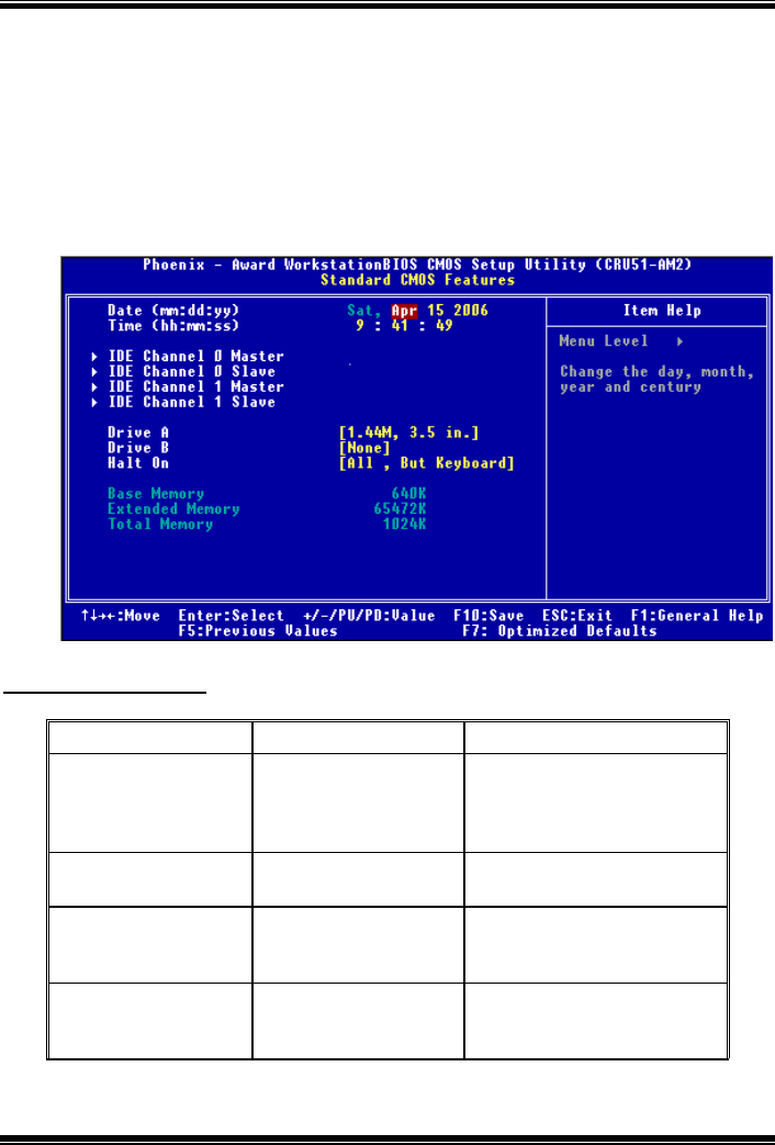
GeForce 6100 AM2 BIOS Setup
46
2.2 Standard CMOS Features
The items in Standard CMOS Setup Menu are divided into several categories.
Each category includes no, one or more than one setup items. Use the arrow keys
to highlight the item and then use the<PgUp> or <PgDn> keys to select the value
you want in each item.
Figure 2: Standard CMOS Setup
Main Menu Selections
This table shows the items and the available options on the Main Menu.
Item Options Description
Date mm : dd : yy
Set the system date. Note
that the ‘Day’ automatically
changes when you set the
date.
Time hh : mm : ss Set the system internal
clock.
IDE Primary Master Options are in its sub
menu.
Press <Enter> to enter the
sub menu of detailed
options
IDE Primary Slave Options are in its sub
menu.
Press <Enter> to enter the
sub menu of detailed
options.

GeForce 6100 AM2 BIOS Setup
47
Item Options Description
IDE Secondary Master Options are in its sub
menu.
Press <Enter> to enter the
sub menu of detailed
options.
IDE Secondary Slave Options are in its sub
menu.
Press <Enter> to enter the
sub menu of detailed
options.
Drive A
Drive B
360K, 5.25 in
1.2M, 5.25 in
720K, 3.5 in
1.44M, 3.5 in
2.88M, 3.5 in
None
Select the type of floppy
disk drive installed in your
system.
Video
EGA/VGA
CGA 40
CGA 80
MONO
Select the default video
device.
Halt On
All Errors
No Errors
All, but Keyboard
All, but Diskette
All, but Disk/ Key
Select the situation in which
you want the BIOS to stop
the POST process and
notify you.
Base Memory N/A
Displays the amount of
conventional memory
detected during boot up.
Extended Memory N/A
Displays the amount of
extended memory detected
during boot up.
Total Memory N/A Displays the total memory
available in the system.
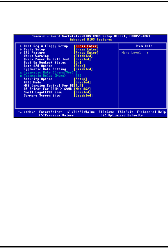
GeForce 6100 AM2 BIOS Setup
48
2.3 Advanced BIOS Features
Figure 3: Advanced BIOS Setup
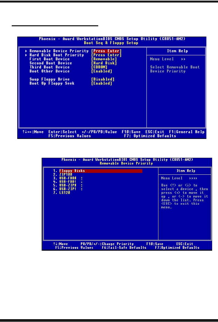
GeForce 6100 AM2 BIOS Setup
49
Boot Seq & Floppy Setup
This item allows you to setup boot sequence & Floppy.
Removable Device Priority
Select Removable Boot Device Priority.
The Choices: Floppy Disks, Zip100, USB-FDD0, USB-FDD1, USB-ZIP0,
USB-ZIP1, LS120.
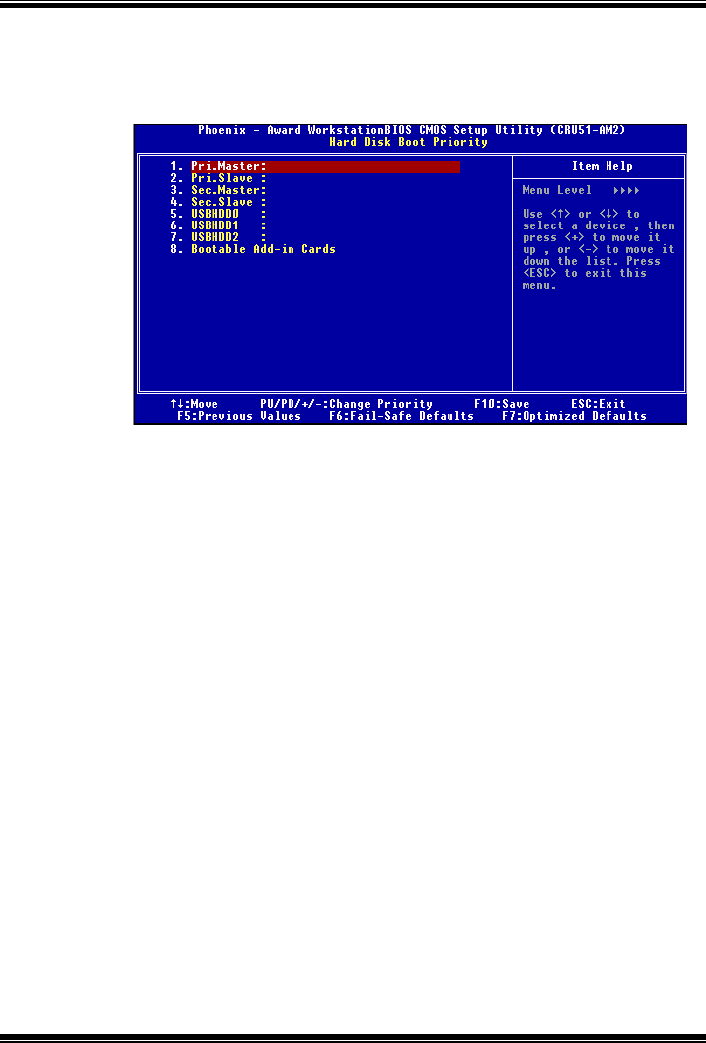
GeForce 6100 AM2 BIOS Setup
50
Hard Disk Boot Priority
The BIOS will attempt to arrange the Hard Disk boot sequence automatically.
You can change the Hard Disk booting sequence here.
The Choices: Pri. Master, Pri. Slave, Sec. Master, Sec. Slave, USB HDD0, USB
HDD1, USB HDD2, and Bootable Add-in Cards.
First/Second/Third Boot Device
The BIOS will attempt to load the operating system in this order.
The Choices: Floppy, LS120, HDD-0, SCSI, CDROM, HDD-1, HDD-2, HDD-3,
ZIP100, LAN, HPT370, Disabled.
Boot Other Device
When enabled, BIOS will try to load the operating system from other device when
it failed to load from the three devices above.
The Choices: Enabled (default), Disabled
Swap Floppy Drive
For systems with two floppy drives, this option allows you to swap logical drive
assignments.
The Choices: Disabled (default), Enabled.
Boot Up Floppy Seek
When enabled, System will test the floppy drives to determine if they have 40 or
80 tracks during boot up. Disabling this option reduces the time it takes to
boot-up.
The Choices: Enabled (default), Disabled.
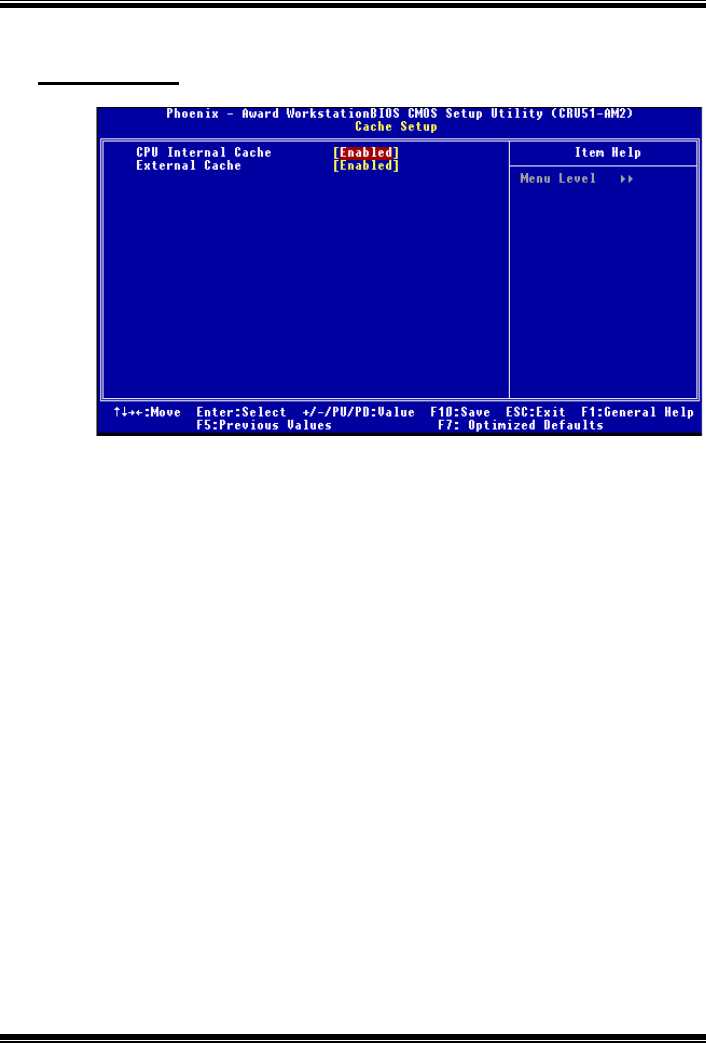
GeForce 6100 AM2 BIOS Setup
51
Cache Setup
CPU Internal Cache
Depending on the CPU/chipset in use, you may be able to increase memory
access time with this option.
Enabled (default) Enable cache.
Disabled Disable cache.
External Cache
This option enables or disables “Level 2” secondary cache on the CPU, which
may improve performance.
Enabled (default) Enable cache.
Disabled Disable cache.
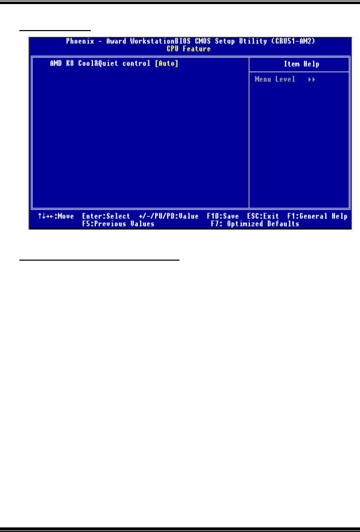
GeForce 6100 AM2 BIOS Setup
52
CPU Feature
AMD K8 Cool&Quiet Control
This function supports AMD Cool ’n’ Quick function.
The Choices: Auto (default),Disable.
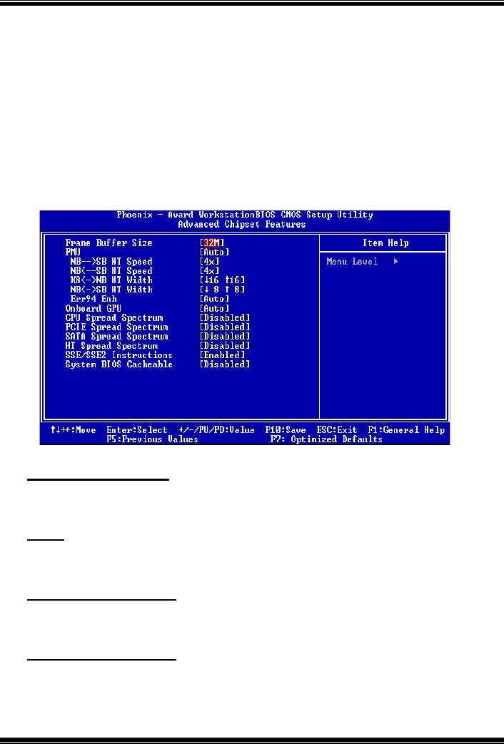
GeForce 6100 AM2 BIOS Setup
53
2.4 Advanced Chipset Features
This submenu allows you to configure the specific features of the chipset installed
on your system. This chipset manage bus speeds and access to system memory
resources, such as DRAM. It also coordinates communications with the PCI bus.
The default settings that came with your system have been optimized and therefore
should not be changed unless you are suspicious that the settings have been
changed incorrectly.
Figure 4. Advanced Chipset Setup
Frame Buffer Size
The Choices: 32M (default), 16M, 64M, 128M, Disabled.
PMU
The Choices: Auto (default), Disabled.
NB-->SB HT Speed
The Choices: 4X (default).1X, 2X, 3X, 5X.
NB<--SB HT Speed
The Choices: 4X (default).1X, 2X, 3X, 5X.

GeForce 6100 AM2 BIOS Setup
54
K8<->NB HT Width
The Choices:↓16 ↑16 (default), ↓8 ↑8.
NB<->SB HT Width
The Choices: ↓8 ↑8 (default), ↓16 ↑16.
Err94 Enh
This item allows you to enable/disable the “sequential Prufetch Feature” of K8
CPU.
The Choices: Auto (default), Disabled.
Onboard GPU
The Choices: Auto (default), Always Enable.
CPU Spread Spectrum
The Choices: Disabled (default), Center, Down.
PCIE Spread Spectrum
This item allows you to disable \ enable the SATA spread spectrum function.
The Choices: Disabled (default), Enabled.
SATA Spread Spectrum
This item allows you to disable \ enable the SATA spread spectrum function.
The Choices: Disabled (default), Enabled.
HT Spread Spectrum
The Choices: Disabled (default), Center, Down.
SSE/SSE2 Instructions
The Choices: Enabled (default), Disabled.

GeForce 6100 AM2 BIOS Setup
55
System BIOS Cacheable
Selecting the “Disabled ” option allows caching of the system BIOS ROM at
F0000h-FFFFFh which can improve system performance. However, any programs
writing to this area of memory will cause conflicts and result in system errors.
The Choices: Disabled (default), Enabled.
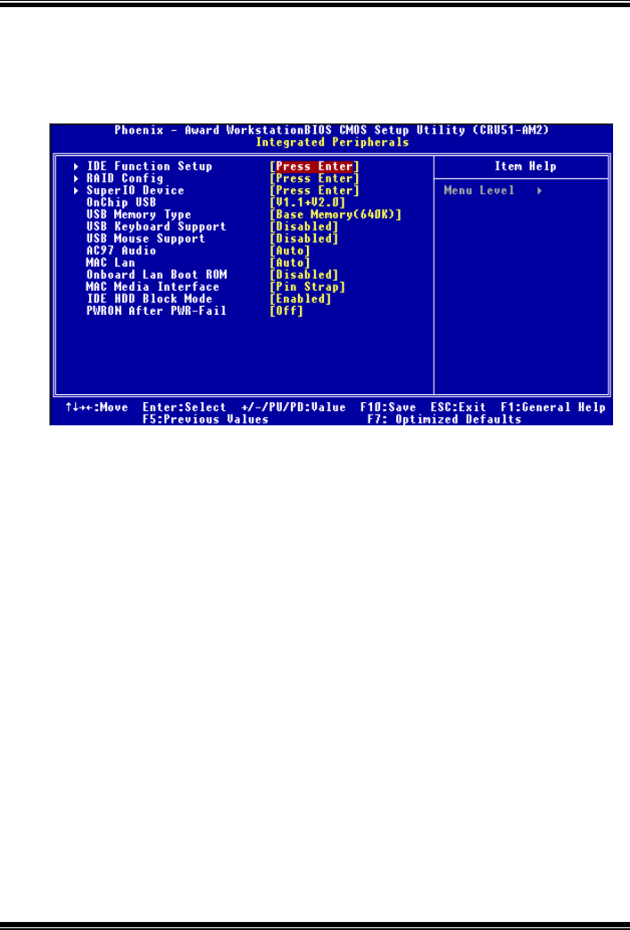
GeForce 6100 AM2 BIOS Setup
56
2.5 Integrated Peripherals
Figure 5. Integrated Peripherals
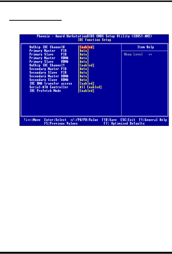
GeForce 6100 AM2 BIOS Setup
57
IDE Function Setup
Highlight the “Press Enter” label next to the “VIA OnChip IDE Device” label and
press enter key will take you a submenu with the following options:
On-chip IDE Channel 0/1
The motherboard chipset contains a PCI IDE interface with support for two IDE
channels. Select “Enabled” to activate the first and/or second IDE interface.
Select “Disabled” to deactivate an interface if you are going to install a primary
and/or secondary add-in IDE interface.
The Choices: Enabled (default), Disabled.
IDE Primary/Secondary/Master/Slave PIO
The IDE PIO (Programmed Input / Output) fields let you set a PIO mode (0-4) for
each of the IDE devices that the onboard IDE interface supports. Modes 0 to 4
will increase performance progressively. In Auto mode, the system automatically
determines the best mode for each device.
The Choices: Auto (default), Mode0, Mode1, Mode2, Mode3, Mode4.
IDE Primary/Secondary/Master/Slave UDMA
Ultra DMA function can be implemented if it is supported by the IDE hard drives
in your system. As well, your operating environment requires a DMA driver
(Windows 95 or OSR2may need a third party IDE bus master driver). If your hard
drive and your system software both support Ultra DMA, select Auto to enable
BIOS support.
The Choices: Auto (default), Disabled.
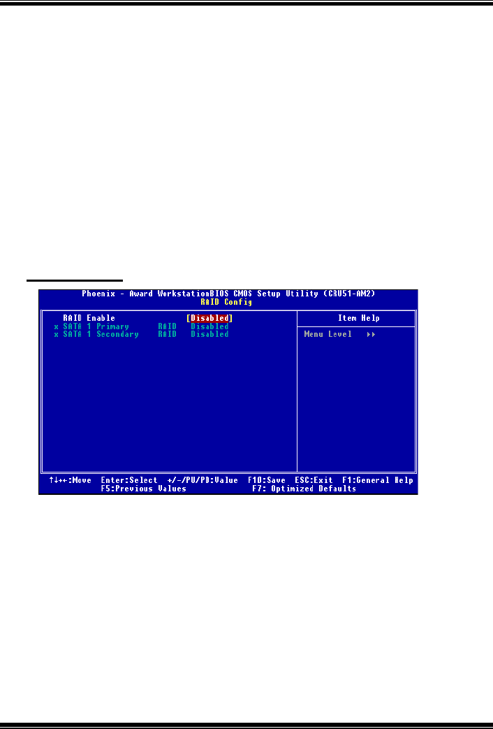
GeForce 6100 AM2 BIOS Setup
58
IDE DMA Transfer Access
This item allows you to enable or disable the IDE DMA transfer access.
The Choices: Enabled (default), Disabled.
OnChip SATA Controller
This option allows you to enable the on-chip Serial ATA.
The Choices: Disabled, All Disabled (default).
IDE Prefetch Mode
The “onboard” IDE drive interfaces supports IDE prefetch function for faster
drive access. If the interface on your drive does not support prefetching, or if you
install a primary and/or secondary add-in IDE interface, set this option to
“Disabled”.
The Choices: Enabled (default), Disabled.
RAID Config
RAID Enable
This option allows you to enable or disable RAID function.
The Choices: Disabled (default), Enabled.
SATA 1/2 Primary/Secondary RAID
This option allows you to enable or disable SATA A Primary/Secondary RAID.
The Choices: Disabled (default), Enabled.
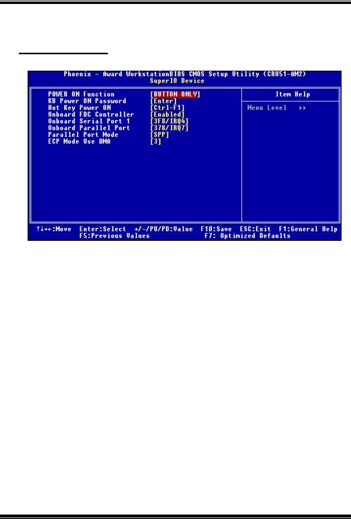
GeForce 6100 AM2 BIOS Setup
59
Super IO Device
Press Enter to configure the Super I/O Device.
Power On Function
This item allows you to choose the power on method.
The Choices: Button Only (default), Password, Hot Key, Mouse Move / Click,
Mouse Double Click, Any Key, Keyboard 98.
KB Power on Password
Input password and press Enter to set the Keyboard power on password.
HOT Key power ON
Choose the Hot Key combination to boot up the system.
The Choices: Ctrl-F1 (default), Ctrl-F2, Ctrl-F3, Ctrl-F4, Ctrl-F5, Ctrl-F6,
Ctrl-F7, Ctrl-F8, Ctrl-F9, Ctrl-F10, Ctrl-F11, Ctrl-F12.
Onboard FDC Controller
Select enabled if your system has a floppy disk controller (FDC) installed on the
system board and you wish to use it. If you installed another FDC or the system
uses no floppy drive, select disabled in this field.
The Choices: Enabled (default), Disabled.

GeForce 6100 AM2 BIOS Setup
60
Onboard Serial Port 1
Select an address and corresponding interrupt for the first and second serial ports.
The Choices: 3F8/IRQ4 (default), Disabled, 2F8/IRQ3, 3E8/IRQ4, 2E8/IRQ3,
Auto.
Onboard Parallel Port
This item allows you to determine access onboard parallel port controller with
which I/O Address.
The Choices: 378/IRQ7 (default), 278/IRQ5, 3BC/IRQ7, Disabled.
Parallel Port Mode
This item allows you to determine how the parallel port should function. The
default value is SPP.
The Choices:
SPP (default) Using Parallel port as Standard Printer Port.
EPP Using Parallel Port as Enhanced Parallel Port.
ECP Using Parallel port as Extended Capabilities Port.
ECP+EPP Using Parallel port as ECP & EPP mode.
ECP Mode Use DMA
Select a DMA Channel for the port.
The Choices: 3 (default), 1.
OnChip USB
This option should be enabled if your system has a USB installed on the system
board. You may need to disable this feature if you add a higher performance
controller.
The Choices: V1.1+V2.0 (default), Disabled, V1.1
USB Memory Type
The item allows you select the type of USB Memory.
The Choices: SHADOW, Base Memory(640K) (default).

GeForce 6100 AM2 BIOS Setup
61
USB Keyboard Support
This item allows you to enable or disable the USB Keyboard Legacy Support.
Enabled Enable USB Keyboard Support.
Disabled (default) Disable USB Keyboard Support.
USB Mouse Support
This item allows you to enable or disable the USB Mouse Legacy Support.
Enabled Enable USB Mouse Support.
Disabled (default) Disable USB Mouse Support.
Onboard AC97 Audio
This item allows you to enable or disable to support AC97 Audio.
The Choices: Auto (default), Disabled.
MAC LAN
This option allows you to control the onboard MAC LAN.
The Choices: Auto (default), Disabled.
Onboard LAN Boot ROM
This item allows you to enable or disable the Onboard LAN Boot ROM.
The Choices: Disabled (default), Enabled.
MAC Media Interface
The Choices: Pin Strap (default).MII.
IDE HDD Block Mode
Block mode is also called block transfer, multiple commands, or multiple sector
read / write. If your IDE hard drive supports block mode (most new drives
do),select Enabled for automatic detection of the optimal number of block
mode(most new drives do), select Enabled for automatic detection of the
optimalnumber of block read / write per sector where the drive can support.
The Choices: Enabled (default), Disabled.

GeForce 6100 AM2 BIOS Setup
62
POWER After PWR-Fail
This setting specifies how your system should behave after a power fail or
interrupts occurs. By choosing off will leave the computer in the power off state.
Choosing On will reboot the computer. Former-Sts will restore the system to the
status before power failure or interrupt occurs.
The Choices: Off (default), On, Former-Sts.
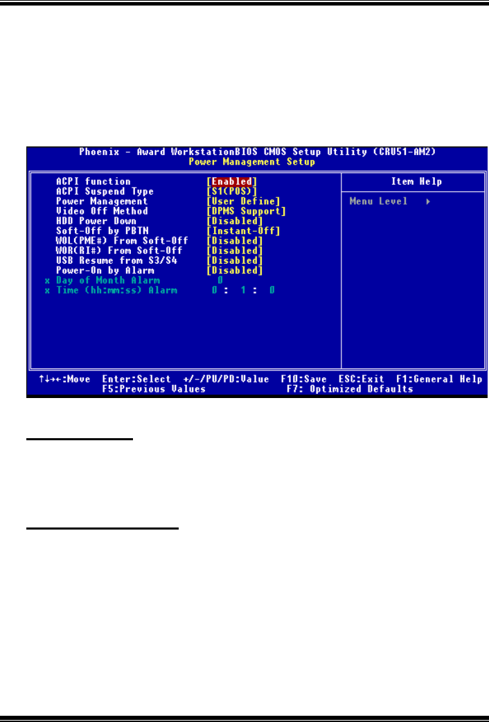
GeForce 6100 AM2 BIOS Setup
63
2.6 Power Management Setup
The Power Management Setup Menu allows you to configure your system to
utilize energy conservation and power up/power down features.
Figure 6. Power Management Setup
ACPI function
This item displays the status of the Advanced Configuration and Power
Management (ACPI).
The Choices: Enabled (default), Disabled.
ACPI Suspend Type
The item allows you to select the suspend type under the ACPI operating system.
The Choices: S1 (POS) (default) Power on Suspend
S3 (STR) Suspend to RAM
S1+S3 POS+STR

GeForce 6100 AM2 BIOS Setup
64
Power Management
This category allows you to select the power saving method and is directly related
to the following modes:
1. HDD Power Down.
2. Suspend Mode.
There are three options of Power Management, three of which have fixed mode
settings
Min. Power Saving
Minimum power management.
Suspend Mode = 1 hr.
HDD Power Down = 15 min
Max. Power Saving
Maximum power management only available for sl CPU’s.
Suspend Mode = 1 min.
HDD Power Down = 1 min.
User Define (default)
Allow you to set each option individually.
When you choose user define, you can adjust each of the item from 1 min. to 1 hr.
except for HDD Power Down which ranges from 1 min. to 15 min.
Video Off Method
This option determines the manner when the monitor goes blank.
V/H SYNC+Blank
This selection will cause the system to turn off the vertical and horizontal
synchronization ports and write blanks to the video buffer.
Blank Screen
This option only writes blanks to the video buffer.
DPMS Support (default)
Initial display power management signaling.
HDD Power Down
When enabled, the hard-disk drives will power down after a set time of system
inactivity. All other devices remain active.
The Choices: Disabled (default), 1 Min, 2 Min, 3 Min, 4 Min, 5 Min, 6 Min, 7
Min, 8 Min, 9 Min, 10 Min, 11 Min, 12 Min, 13 Min, 14 Min, 15Min.

GeForce 6100 AM2 BIOS Setup
65
Soft-Off by PWR-BTN
This item determines the behavior of system power button. Instant off turn off the
power immediately, and Delay 4 Sec. will require you to press and hold the power
button for 4 seconds to cut off the system power.
The Choices: Delay 4 Sec, Instant-Off (default).
WOL(PME#)/ From Soft-Off
This item allows you to enable or disable Wake On LAN from Soft-Off function.
The Choices: Disabled (default), Enabled.
WOR(RI#) From Soft-Off
This item allows you to enable or disable Wake On Ring from Soft-Off function.
The Choices: Disabled (default), Enabled.
USB Resume from S3/S4
This item allows you to wake up from S3 with USB device.
The Choices: Disabled (default), Enabled.
Power-On by Alarm
This function is for setting date and time for your computer to boot up. When
enabled, you can choose the date and time to boot up the system.
The Choices: Disabled (default), Enabled.
Date (of Month) Alarm
You can choose which month the system will boot up.
Time (hh:mm:ss) Alarm
You can choose the system boot up time, input hour, minute and second to specify.
Note: If you have change the setting, you must let the system boot up until it goes
to the operating system, before this function will work.
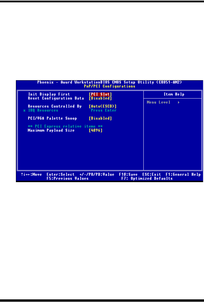
GeForce 6100 AM2 BIOS Setup
66
2.7 PnP/PCI Configurations
This section describes configuring the PCI bus system. PCI, or Personal Computer
Interconnect, is a system which allows I/O devices to operate at speeds nearing the
speed of the CPU itself uses when communicating with its own special
components. This section covers some very technical items and it is strongly
recommended that only experienced users should make any changes to the default
settings.
Figure 7: PnP/PCI Configurations

GeForce 6100 AM2 BIOS Setup
67
Init Display First
This item allows you to decide to active whether PCI Slot or on-chip VGA first.
The Choices: PCEx, Onboard ,PCI Slot (default).
Reset Configuration Data
The system BIOS supports the PnP feature which requires the system to record
which resources are assigned and protects resources from conflict.
Every peripheral device has a node, which is called ESCD. This node records
which resources are assigned to it. The system needs to record and update ESCD
to the memory locations. These locations are reserved in the system BIOS. If the
Disabled (default) option is chosen, the system‘s ESCD will update only when the
new configuration varies from the last one. If the Enabled option is chosen, the
system is forced to update ESCDs and then is automatically set to the “Disabled”
mode.
The above settings will be shown on the screen only if “Manual” is chosen for the
resources controlled by function.
Legacy is the term, which signifies that a resource is assigned to the ISA Bus and
provides non-PnP ISA add-on cards. PCI / ISA PnP signify that a resource is
assigned to the PCI Bus or provides for ISA PnP add-on cards and peripherals.
The Choices: Disabled (default), Enabled.
Resources Controlled By
By Choosing “Auto(ESCD)” (default), the system BIOS will detect the system
resources and automatically assign the relative IRQ and DMA channel for each
peripheral. By Choosing “Manual”, the user will need to assign IRQ & DMA for
add-on cards. Be sure that there are no IRQ/DMA and I/O port conflicts.
The Choices: Auto (ESCD) (default), Manual.

GeForce 6100 AM2 BIOS Setup
68
IRQ Resources
This submenu will allow you to assign each system interrupt a type, depending on
the type of device using the interrupt. When you press the “Press Enter” tag, you
will be directed to a submenu that will allow you to configure the system interrupts.
This is only configurable when “Resources Controlled By” is set to “Manual”.
IRQ-3 assigned to PCI Device
IRQ-4 assigned to PCI Device
IRQ-5 assigned to PCI Device
IRQ-7 assigned to PCI Device
IRQ-9 assigned to PCI Device
IRQ-10 assigned to PCI Device
IRQ-11 assigned to PCI Device
IRQ-12 assigned to PCI Device
IRQ-14 assigned to PCI Device
IRQ-15 assigned to PCI Device
PCI / VGA Palette Snoop
Some old graphic controllers need to “snoop” on the VGA palette and then map it
to their display as a way to provide boot information and VGA compatibility. This
item allows such snooping to take place.
The Choices: Disabled (default), Enabled.
Maximum Payload Size
Set the maximum payload size for Transaction packets (TLP).
The Choice: 4096 (default.), 128, 256, 512, 1024, 2048.
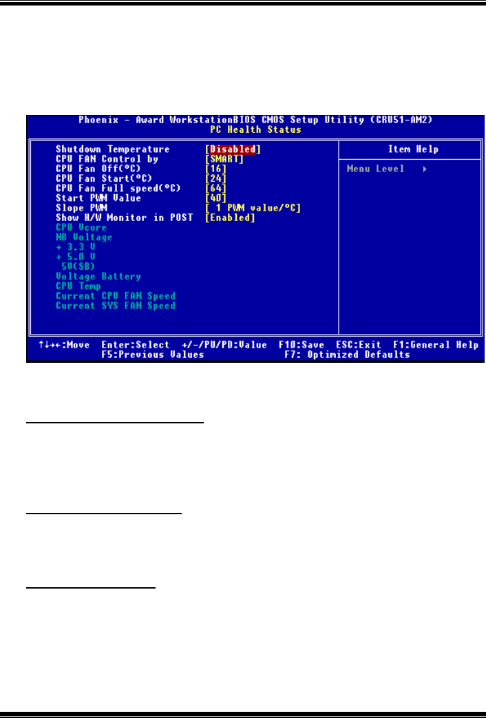
GeForce 6100 AM2 BIOS Setup
69
2.8 PC Health Status
Figure 8: PC Health Status
Shutdown Temperature
This item allows you to set up the CPU shutdown Temperature. This item is only
effective under Windows 98 ACPI mode.
The Choices: Disabled (default) , 60℃/140F, 65℃/149F, 70℃/158F.
CPU FAN Control by
Choose “smart” to reduce the noise caused by CPU FAN.
The Choices: Smart (default), Always On.
CPU Fan Off<℃>
If the CPU Temperature is lower than the set value, FAN will turn off.
The Choices: 16 (default).
Min= 0, Max= 127, you can key in a DEC number.

GeForce 6100 AM2 BIOS Setup
70
CPU Fan Start<℃>
CPU fan starts to work under smart fan function when arrive this set value.
The Choices: 24 (default).
Min= 0, Max= 127, you can key in a DEC number.
CPU Fan Full speed <℃>
When CPU temperature is reach the set value, the CPU fan will work under Full
Speed.
The Choices: 64 (default).
Min= 0, Max= 127, you can key in a DEC number.
Start PWM Value
When CPU temperature arrives to the set value, the CPU fan will work under
Smart Fan Function mode. The range is from 0~127, with an interval of 1.
The Choices: 40 (default).
Min= 0, Max= 127, you can key in a DEC number.
Slope PWM
Increasing the value of slope PWM will raise the speed of CPU fan.
The Choices: 0 PWM Value/℃, 1 PWM Value/℃ (default), 2 PWM Value/℃, 4
PWM Value/℃, 8 PWM Value/℃, 16 PWM Value/℃, 32 PWM Value/℃,
64PWM Value/℃.
Show H/W Monitor in POST
If you computer contains a monitoring system, it will show PC health status during
POST stage. The item offers several different delay times.
The Choices: Enabled (default), Disabled.
CPU Vcore, NB Voltage, +3.3V, +5.0V, 5V (SB), Voltage
Battery
Detect the system’s voltage status automatically.
Current CPU Temp
This field displays the current temperature of CPU.

GeForce 6100 AM2 BIOS Setup
71
Current CPU FAN Speed
This field displays the current speed of CPU fan.
Current SYS FAN Speed
This field displays the current speed of SYSTEM fan.
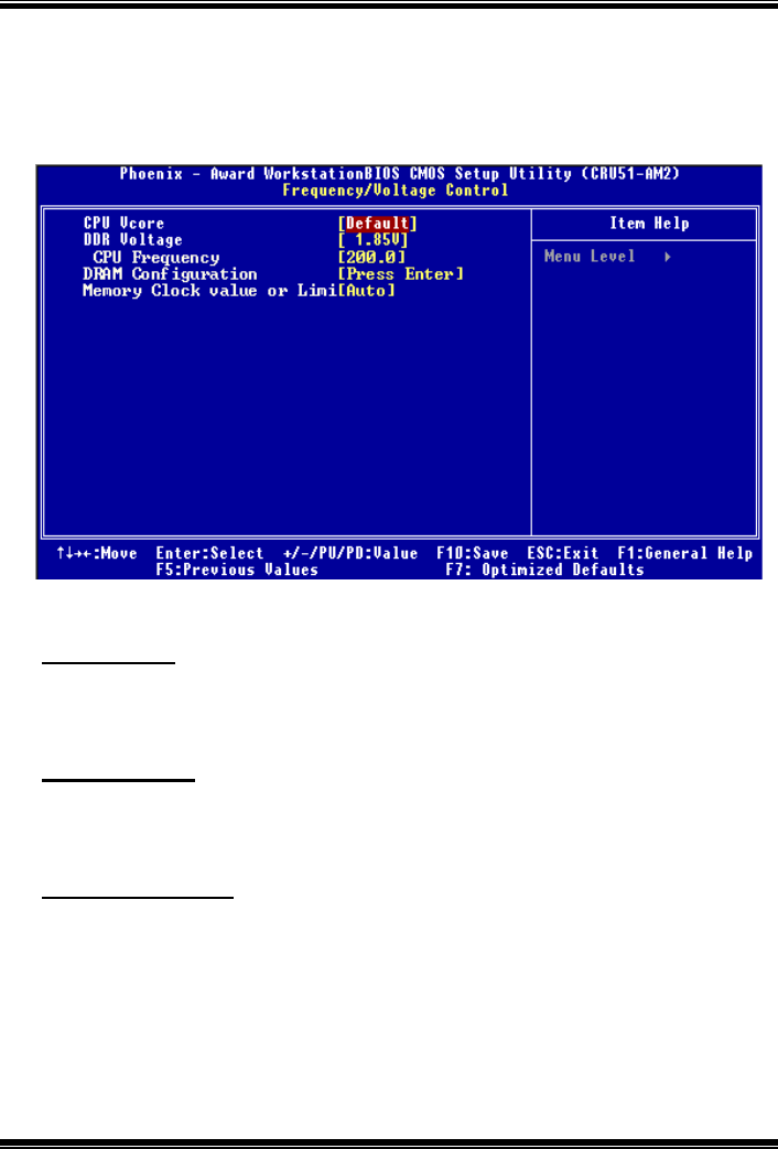
GeForce 6100 AM2 BIOS Setup
72
2.9 Frequency/ Voltage Control
Figure 9: Frequency/ Voltage Control
CPU Vcore
This item allows you to select CPU Vcore.
The Choices: Default (default), +0.15V,+0.10V,+0.05V.
DDR Voltage
This item allows you to select DDR Voltage Regulator
The Choices: 1.85V (default), 1.90V, 1.95V,2.0V.
CPU Frequency
This item allows you to select the CPU Frequency
The Choices: 200 (default), 201, 202, 203, 204, 205, 206, 207. 208, 209 … 450
( Max is 450)
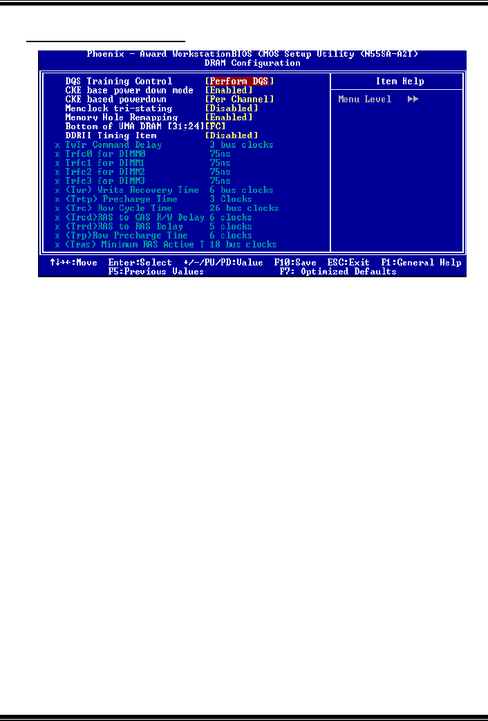
GeForce 6100 AM2 BIOS Setup
73
DRAM Configuration
DQS Training Control
The Choices: Perform DQS (default), Skip DQS.
CKE base power down mode
The Choices: Enabled (default), Disabled.
CKE based power down
The Choices: Per Channel (default), Per CS.
Memclock tri-stating
The Choices: Disabled (default), Enabled.
Memory Hole Remapping
The Choices: Enabled (default), Disabled.
Auto Optimize Bottom IO
The Choices: Enabled (default), Disabled.
Bottom of [31:24] IO space
The Choices: C0 (default).
DDRII Timing Item
The Choices: Disabled (default), Enabled.
TwTr Command Delay
The Choices: 3 bus clocks (default).

GeForce 6100 AM2 BIOS Setup
74
TrTfc0 for DIMM0
The Choices: 75ns (default).
TrTfc1 for DIMM1
The Choices: 75ns (default)
TrTfc2 for DIMM2
The Choices: 75ns (default)
TrTfc3 for DIMM3
The Choices: 75ns (default)
<Twr> Write Recovery Time
The Choices: 6 bus clocks (default).
<Trtp> Precharge Time
The Choices: 3 clocks (default).
<Trc> Row Cycle Time
The Choices: 26 bus clocks (default).
<Trcd> RAS to CAS R/W Delay
The Choices: 6 clocks (default).
<Trrd> RAS to RAS Delay
The Choices: 5 clocks (default).
<Trp> Row Precharge Time
The Choices: 6 clocks (default).
<Tras> Minimum RAS Active T
The Choices: 18 bus clocks (default).
