Biostar P4M890 M7 Fe Owners Manual P4M90 M7C_P4M89 M7C_080407
2014-07-31
: Biostar Biostar-P4M890-M7-Fe-Owners-Manual biostar-p4m890-m7-fe-owners-manual biostar pdf
Open the PDF directly: View PDF ![]() .
.
Page Count: 43

P4M900-M7 FE/P4M890-M7 FE Setup Manual
FCC Information and Copyright
This equipment has been tested and found to comply with the limits of a Class
B digital device, pursuant to Part 15 of the FCC Rules. These limits are designed
to provide reasonable protec tion against harmful interference in a residential
installation. This equipment generates, uses, and can radiate radio frequency
energy and, if not installed and used in accordance with the instructions, may
cause harmful interference to radio communications. There is no guarantee
that interference will not occur in a particular ins tallation.
The vendor makes no representa tions or warranties wi th respec t to the
contents here and specially disclaims any implied warranties of merchantability
o r fi tness fo r a ny pu rpose . F urt he r t he ve nd o r rese rves t he ri g ht to rev ise t his
publication and to make changes to the contents here without obligation to
notify any party beforehand.
D uplication of this publication, in part or in whole , is not allowed without first
obtaining the vendor’s approval in writing.
The content of this user’s manual is subject to be changed without notice and
we will not be res ponsible for any mis takes found in this user’s manual. All the
brand and product names are trademarks of their respective companies.

Table of Contents
Chapter 1: Introduction.....................................................3
1.1 Before You Start...................................................................3
1.2 Package Checklist................................................................ 3
1.3 Motherboard Features.......................................................... 4
1.4 Rear Panel Connectors..........................................................5
1.5 Motherboard Layout............................................................6
Chapter 2: Hardware Installation........................................7
2.1 Installing Central Processing Unit (CPU)................................7
2.2 Fan Headers......................................................................... 9
2.3 Installing System Memory.....................................................10
2.4 Connectors and Slots............................................................12
Chapter 3: Headers & Jumpers Setup.................................14
3.1 How to Setup Jumpers..........................................................14
3.2 Detail Settings.....................................................................14
Chapter 4: RAID Functions...............................................20
4.1 Operation System................................................................20
4.2 Raid Arrays.........................................................................20
4.3 How RAID Works.................................................................20
Chapter 5: Useful Help.....................................................22
5.1 Driver Installation Note .......................................................22
5.2 Award BIOS Beep Code........................................................23
5.3 Extra Information................................................................23
5.4 Troubleshooting...................................................................24
Appendencies: SPEC In Other Language.............................26
German................................................................................................26
France..................................................................................................28
Italian..................................................................................................30
Spanish................................................................................................32
Portuguese...........................................................................................34
Polish...................................................................................................36
Russian................................................................................................38
Arabic..................................................................................................40
Japanese..............................................................................................42

P4M900-M7 FE/P4M890-M7 FE
3
CHAPTER 1: INTRODUCTION
1.1 BEFORE YOU START
Tha nk yo u for choosing our product. Before you start installing the
mo the rboa rd , plea se make sure you fo llo w the instructions be lo w:
Prepare a dry and stable working environment with
s uf ficie nt ligh ting .
Always disconnect the computer from power outlet
be fo re ope ra tion.
Befo re you take the mo the rboa rd ou t from a n ti-s ta tic
bag, ground yourself properly by touching any safely
grounde d appliance, o r use grounded wrist strap to
remove the static charge.
Avo id tou ch ing the compone nts o n m o the rboa rd o r the
rear side of the board unless necessary. Hold the boa rd
on the edge, do not try to bend or flex the board.
Do not lea ve any unfastene d small pa rts inside the
case after installation. Loose parts will cause short
circuits which ma y damage the equipment.
Keep the computer from dangerous area, such as heat
source , humid a ir and wa ter.
1.2 PACKAGE CHECKLIST
HDD Cable X 1
I ns talla tion Gu ide X 1
Fu lly Se tup Drive r C D X 1 (fu ll ve rs ion manua l files ins ide )
Rear I/O Panel for ATX Case X 1
FDD Cable X 1 (optional)
Se ria l ATA Cab le X 1 ( op tiona l)
USB 2.0 Cable X1 (optional)
Se ria l ATA Po we r Cab le X 1 (o ptio nal)
Note: The package contents may differ by area or your motherboard version.

Motherboard Manual
4
1.3 MOTHERBOARD FEATURES
P4M900-M7 FE P4M890-M7 FE
CPU
LGA 775
Intel Core2Duo/ Pentium 4 / Pentium D /
Celeron D / Cel eron 4xx pr ocessor up to 3.8
GHz
*It is recommended to use
p
rocessors with
95W power co nsumption.
Supports Hyper Threading
/
Ex ecute Disable
Bit/ Enhanced Intel S peedStep®/ Intel
Extended Memory 64 technology
LGA 775
Intel Core2Duo/ Pentium 4 / Pentium D /
Celeron D / Cel eron 4xx pr ocessor up to 3.8
GHz
*It is recommended to use
p
rocessors with
95W power co nsumption.
Supports Hyper Threading
/
Ex ecute Disable
Bit/ Enhanced Intel S peedStep®/ Intel
Extended Memory 64 technology
FSB 533 / 80 0 / 1 06 6 MHz 533 / 80 0 / 1 06 6 MHz
Chipset VIA P4M900
VIA VT8237A
VIA P4M890
VIA VT8237A
Graphic Chrome9 HC 3D / 2 D Grap hics
Max Shared Video Memory is 256 MB
Chrome9 HC 3D / 2 D Grap hics
Max Shared Video Memory is 256 MB
Super I/O
ITE 8712F
Provides the most commonly used legacy
Super I/O functionality.
Low Pin C ount Interf ace
Environment Control initiatives,
H/W Monitor
Fan Spee d Co ntroller
ITE's "Smart G uardia n" fu nction
ITE 8712F
Provides the most commonly used legacy
Super I/O functionality.
Low Pin C ount Interf ace
Environment Control initiatives,
H/W Monitor
Fan Spee d Co ntroller
ITE's "Smart G uardia n" fu nction
Main
Memory
DIMM Slots x 2
Supports D DR2 533 / 667
Eac h DIMM sup ports 2 56/ 51 2MB/1GB/ 2GB
DDR2
Max Memory C apicity 4GB
Single Channel Mode DDR2 memory
module
Registered DIMM and ECC DIMM is not
supported
DIMM Slots x 2
Supports D DR2 533 / 667
Eac h DIMM sup ports 2 56/ 51 2MB/1GB/ 2GB
DDR2
Max Memory C apicity 4GB
Single Channel Mode DDR2 memory
module
Registered DIMM and ECC DIMM is not
supported
IDE
Integrated IDE Controller
Ultra DMA 33~133 Bus Master Mode
supports PIO Mo de 0~4,
Integrated IDE Controller
Ultra DMA 33~133 Bus Master Mode
supports PIO Mo de 0~4,
SATA
Integrated Serial ATA Controller
Data transfer rates up to 1.5 Gb/s.
SATA Version 1.0 specification compliant.
Integrated Serial ATA Controller
Data transfer rates up to 1.5 Gb/s.
SATA Version 1.0 specification compliant.
LAN PHY
Realtek RTL 8201CL PHY
10 / 100 Mb/s auto negotiation
Half / Full duplex capability
Realtek RTL 8201CL PHY
10 / 100 Mb/s auto negotiation
Half / Full duplex capability
Sound
Codec
ALC662
5.1 cha nnels a udio o ut
High- Defi nition Au dio s upport
ALC662
5.1 cha nnels a udio o ut
High- Defi nition Au dio s upport

P4M900-M7 FE/P4M890-M7 FE
5
P4M900-M7 FE P4M890-M7 FE
PCI Express x 16 slot x1 PCI Express x 16 slot x1
PCI Express x 1 slot x1 PCI Express x 1 slot x1 Slots
PCI slot x2 PCI slot x2
Floppy connector x1 Floppy connector x1
Printer Port C onnector x1 Printer Port C onnector x1
IDE Co nnector x2 IDE Co nnec tor x2
SATA Connector x2 SATA Connector x2
Front Pa nel Co nnec tor x1 Front Pa nel Co nnector x1
Front Audi o Connector x1 Front Audi o Co nnector x1
CD-in Co nnector x1 CD-in Co nnector x1
CPU Fan hea der x1 CPU Fan hea der x1
System Fan hea der x1 System Fan hea der x1
Clear CMOS header x1 Clear CMOS header x1
USB connector x2 USB connector x2
Power Connector ( 24pi n) x1 Power Connector (24pin) x1
On Board
Connector
Power Connector ( 4pin) x1 Power Connector (4pin) x1
Back Panel
I/O
PS/2 Keyboard x1
PS/2 Mo use x1
Serial Port x1
VGA Port x1
LAN port x1
USB Port x4
Audio Jack x3
PS/2 Keyboard x1
PS/2 Mo use x1
Serial Port x1
VGA Port x1
LAN port x1
USB Port x4
Audio Jack x3
Board Siz e 190 mm (W) x 24 4 mm (L) 190 mm (W) x 24 4 mm (L)
Special
Feature RAID 0 / 1 support RAID 0 / 1 support
OS
Support
Windows 2000 / XP / VISTA
Biostar Reserves the ri
g
ht to add or remo ve
support for any OS with or without notice.
Windows 2000 / XP
Biostar Reserves the ri
g
ht to add or remove
support for any OS with or without notice.
1.4 REAR PANEL CONNECTORS
PS/2
Mouse
PS/2
Keyboard
USBX2USBX2
LA N
COM1 VGA
Li ne I n /
Surround
Lin e O ut
Mic In 1/
Bass/ Center
Since t he audio c hip s uppor ts Hig h Definiti on A udio Specific atio n, t he func tion of eac h a udi o
jack c an be d efine d by sof tware. T he in put / out put fu nctio n o f e ach au dio jac k listed ab o ve
represe nts t he def ault s etti ng. Ho wever , wh en c onnecti ng exter nal microph on e t o t he au dio
port, pleas e us e t he Lin e I n (blu e) an d Mic In (Pin k) a udio j ac k.

Motherboard Manual
6
1.5 MOTHERBOARD LAYOUT
Super
I/O
DIMM1
DIMM2
FDD1
PCI-EX1 _1
PCI-E X16
PCI1
PCI2
J P AN EL 1
JU SB 2
JUSB3
JATXPWR1
JCFAN1
JATXPWR2
JSATA1
JSATA2
Codec
JC DIN1
JSFAN1
BAT1
VIA
VT8237A
LGA775
CPU 1
P4M900
or
P4M890
JAUDI O F1
JKB MS1
JUSB1
JUSBLAN1
C
OM1
JCO
M1
JVGA1
IDE1
JCMOS1
LAN
IDE2
BIOS
JAUDIO1
JPRNT1
JUSBV2
JUSBV1
Note: represents the 1■st pin.

P4M900-M7 FE/P4M890-M7 FE
7
CHAPTER 2: HARDWARE INSTALLATION
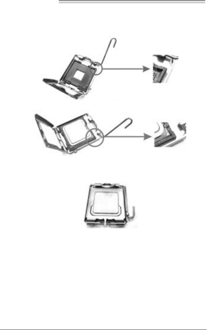
2.1 INSTALLING CENTRAL PROCESSING UNIT (CPU)
Special Notice:
Remove Pin Cap before installation, and make good preservation
for future use. When the CPU is removed, cover the Pin Cap on the
empty socket to ensure pin legs won’t be damaged.
Pin Cap
Step 1: Pull the socket locking lever out from the socket and then raise
the lever up to a 90-degree angle.
Motherboard Manual
8
Step 2: Look for the triangular cut edge on socket, and the golden dot on
CPU should point forwards this triangular cut edge. The CPU will
fit only in the correct orientation.
Step 2-1:
Step 2-2:
Step 3: Hold the CPU down firmly, and then lower the lever to locked
position to complete the installation.
Step 4: Put the CPU Fan and heatsink assembly on the CPU and buckle it
on the retention frame. Connect the CPU FAN power cable into
the JCFAN1. This completes the installation.

P4M900-M7 FE/P4M890-M7 FE
9
2.2 FAN HEADERS
These fan headers support cooling-fans built in the computer. The fan
cable and connector may be different according to the fan manufacturer.
Connect the fan cable to the connector while matching the black wire to
pin#1.
JCFAN1: CPU Fan Header
Pin
Assignment
1 Ground
2 +12V
3 FAN RPM rate
sense
14
4 Smart Fan
Control
JSFAN1: System Fan Header
Pin
Assignment
1 Ground
2 +12V
13
3 FAN RPM rate
sense
Note:
The JSFAN1 sup por ts 3- pin he ad c on nect or and the JCFAN1 supports 4- pi n he ad
conn ector. When c onnecti ng with wir es onto c onnect ors, pl ease note th at t he r ed wire is
the posi ti ve a nd s houl d be c onnect ed to pi n# 2, and the blac k wire is Gr o un d a nd s hould
be c onn ect ed t o GND.

Motherboard Manual
10
2.3 INSTALLING SYSTEM MEMORY
A. Memory Modules
DIM M1
DIM M2
1. Unlock a DIMM slot by pressing the retaining clips outward. Align a
DIMM on the slot such that the notch on the DIMM matches the
break on the Slot.

P4M900-M7 FE/P4M890-M7 FE
11
2. Insert the DIMM vertically and firmly into the slot until the retaining
chip snap back in place and the DIMM is properly seated.
B. Memory Capacity
DIMM Socket
Location DDR2 Module To t al Me mo r y
Size
DIMM1 256MB/512MB/1GB/2GB
DIMM2 256MB/512MB/1GB/2GB
Max is 4GB.

Motherboard Manual
12
2.4 CONNECTORS AND SLOTS
FDD1: Floppy Disk Connector
The motherboard prov ides a standard floppy disk connector that supports 360K,
720K, 1.2M, 1.44M and 2.88M floppy disk ty pes. This connector supports the
prov ided f loppy drive ribbon cable.
34
33
1
2
IDE1/IDE2: Hard Disk Connectors
The motherboard has a 32-bit Enhanced PCI IDE Controller that prov ides PIO
Mode 0~4, Bus Master, and Ultra DMA 33/66/100/133 f unctionality. It has two
HDD connectors: IDE1 (primary ) and IDE2 (secondary ).
The IDE connectors can connect a master and a slav e driv e, so you can
connect up to four hard disk drives. The f irst hard drive should always be
connected to IDE1.
IDE2IDE1
21
3940

P4M900-M7 FE/P4M890-M7 FE
13
PCI-EX16: PCI-Express x16 Slot
- PCI-Express 1.0a compliant.
- Maximum theoretical realized bandwidth of 4GB/s simultaneously per
direction, f or an aggregate of 8GB/s totally.
PCI-EX1_1: PCI-Express x1 Slot
- PCI-Express 1.0a compliant.
- Data transf er bandwidth up to 250MB/s per direction; 500MB/s in total.
- PCI-Express supports a raw bit-rate of 2.5Gb/s on the data pins.
- 2X bandwidth ov er the traditional PCI architecture.
PCI-EX16
PCI-EX1_1
PCI1/PCI2: Peripheral Component Interconnect Slots
This motherboard is equipped with 2 standard PCI slots. PCI stands f or
Peripheral Component Interconnect, and it is a bus standard for expansion
cards. This PCI slot is designated as 32 bits.
PCI1
PCI2

Motherboard Manual
14
CHAPTER 3: HEADERS & JUMPERS SETUP
3.1 HOW TO SET UP JUMPERS
The illustration shows how to set up jumpers. When the jumper cap is
placed on pins, the jumper is “close”, if not, that means the jumper is
“open”.
Pin opened Pin closed Pin1-2 closed
3.2 DETAIL SETT INGS
JPANEL1: Front Panel Header
This 16-pin connector includes Power-on, Reset, HDD LED, Power LED, and
speaker connection. It allows user to connect the PC case’s front panel switch
functions.
18
16
PWR_LED
On/ Off
RST
HL ED
SPK
++
+
9
-
-
Pin Assignment Function Pin Assignment Function
1 +5V 9 N/A
2 N/A 10 N/A N/A
3 N/A 11 N/A N/A
4 Speaker
Speaker
Connector
12 Power LED (+)
5 HDD LED (+) 13 Power LED (+)
6 HDD LED (-)
Hard drive
LED 14 Power LED (-)
Power LED
7 Ground 15 Power button
8 Reset control Reset button 16 Ground Power-on button

P4M900-M7 FE/P4M890-M7 FE
15
ATX Power Source Connector: JATXPWR1
JATXPWR1 allows user to connect 24-pin power connector on the ATX power
supply.
1
12
13
24
Pin Assignment Pin Assignment
13 +3.3V 1 +3.3V
14 -12V 2 +3.3V
15 Ground 3 Ground
16 PS_ON 4 +5V
17 Ground 5 Ground
18 Ground 6 +5V
19 Ground 7 Ground
20 NC 8 PW_OK
21 +5V 9 Standby Voltage+5V
22 +5V 10 +12V
23 +5V 11 +12V
24 Ground 12 +3.3V
JATXPW R2: ATX Power S ou rce C onne ctor
By connecting this connector, it will provide +12V to CPU power circuit.
Pin
Assignment
1 +12V
2 +12V
3 Ground
1
23
4
4 Ground
Note:
Befor e p ower on t he s yst e m, pleas e make sure th at b ot h J ATXP WR1 and JAT XPWR2
conn ectors have b ee n pl ugg ed- in.

Motherboard Manual
16
JUSB2/JUSB3: Headers for USB 2.0 Ports at Front Panel
This header allows user to connect additional USB cable on the PC f ront panel,
and also can be connected with internal USB devices, like USB card reader.
Pin
Assignment
1 +5V (fused)
2 +5V (fused)
3 USB-
4 USB-
5 USB+
6 USB+
7 Ground
8 Ground
9 Key
19
210
JUSB2
JUSB3
10 NC
JSATA1/JSATA2: Serial ATA Connectors
The motherboard has a PCI to SATA Controller with 2 channels SATA interf ace,
it satisfies the SATA 1.0 spec and with transfer rate of 1.5Gb/s.
Pin
Assignment
1 Ground
2 TX+
3 TX-
4 Ground
5 RX-
6 RX+
14 7
J SATA 1
JSATA2
147
7 Ground
JAUDIOF1: Front Panel Audio Header
This header allows user to connect the front audio output cable with the PC f ront
panel. This header allows only HD audio front panel connector; AC’97 connector
is not acceptable.
Pin Assignment
1 Mic Left in
2 Ground
3 Mic Right in
4 GPIO
5 Right line in
6 Jack Sense
7 Front Sense
8 Key
9 Left line in
10 Jack Sense
19
210

P4M900-M7 FE/P4M890-M7 FE
17
JCDIN1: CD-ROM Audio-in Connector
This connector allows user to connect the audio source f rom the v ariaty dev ices,
like CD-ROM, DVD-ROM, PCI sound card, PCI TV turner card etc.
Pin
Assignment
1 Left Channel Input
2 Ground
3 Ground
14
4 Right Channel Input
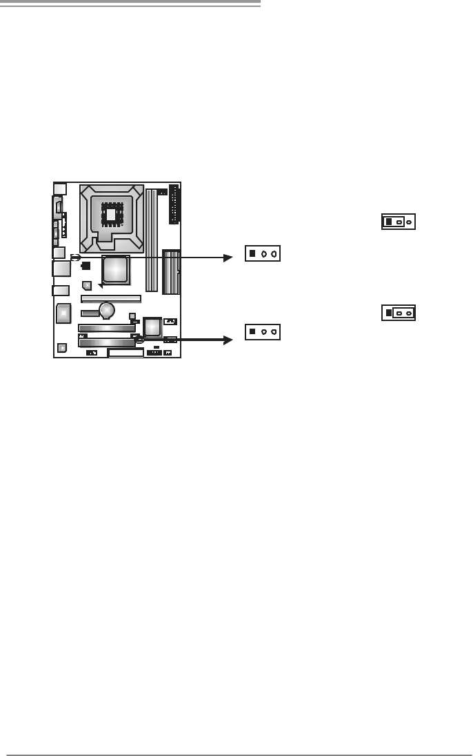
JCMOS1: Clear CMOS Header
By placing the jumper on pin2-3, it allows user to restore the BIOS saf e setting
and the CMOS data, please carefully f ollow the procedures to avoid damaging
the motherboard.
13
Pin 1-2 Close:
Normal Operation (default).
13
13
Pin 2-3 Close:
Clear CMOS data.
※ Clear CMOS Procedures:
1. Remov e AC power line.
2. Set the jumper to “Pin 2-3 close”.
3. Wait f or f ive seconds.
4. Set the jumper to “Pin 1-2 close”.
5. Power on the AC.
6. Reset y our desired password or clear the CMOS data.

Motherboard Manual
18
JPRNT1: Printer Port Connector
This header allows you to connector printer on the PC.
1
25
2
Pin Assignment Pin Assignment
1 -Strobe 14 Ground
2 -ALF 15 Data 6
3 Data 0 16 Ground
4 -Error 17 Data 7
5 Data 1 18 Ground
6 -Init 19 -ACK
7 Data 2 20 Ground
8 -Scltin 21 Busy
9 Data 3 22 Ground
10 Ground 23 PE
11 Data 4 24 Ground
12 Ground 25 SCLT
13 Data 5 26 Key
P4M900-M7 FE/P4M890-M7 FE
19
JUSBV1/JUSBV2: Powe r Source Heade rs for USB Ports
Pin 1-2 Close:
JUSBV1: +5V for USB ports at JUSB1/JUSBLAN1.
JUSBV2: +5V for USB ports at f ront panel (JUSB2/JUSB3).
Pin 2-3 Close:
JUSBV1: +5V STB for USB ports at JUSB1/JUSBLAN1.
JUSBV2: +5V STB for USB ports at f ront panel (JUSB2/JUSB3).
13
Pin 1-2 close
13
JUSBV1
13
JU SBV 2
13
Pin 2-3 close

Motherboard Manual
20
CHAPTER 4: RAID FUNCTIONS
4.1 OPERATION SYSTEM
Supports Windows XP, Windows 2000 Professional, and Windows Vista.
4.2 RAID ARRAYS
RAID supports the following types of RAID arrays:
RAID 0: RAID 0 defines a disk striping scheme that improves disk read and write times for
many applications.
RAID 1: RAID 1 defines techniques for mirroring data.
4.3 HOW RAID WORKS
RAID 0:
The controller “ stripes” data across multiple drives in a RAID 0 array system. It breaks
up a large file into smaller blocks and performs disk reads and writes across multiple
drives in parallel. The size of each block is determined by the stripe size parameter,
which you set during the creation of the RAID set based on the system environment. This
technique reduces overall disk access time and offers high bandwidth.
Features and Benefits
Drives: Minimum 2, and maximum is up to 6 or 8. Depending on the
platf orm.
Uses: Intended for non-critical data requiring high data throughput, or any
env ironment that does not require f ault tolerance.
Benefits: prov ides increased data throughput, especially f or large files. No
capacity loss penalty f or parity.
Drawbacks: Does not deliver any fault tolerance. If any drive in the array
f ails, all data is lost.
Fault Tolerance: No.
Blo ck 1
Block 3
Block 5
Block 2
Block 4
Block 6

P4M900-M7 FE/P4M890-M7 FE
21
RAID 1:
Every read and write is actually carried out in parallel across 2 disk drives in a RAID 1
array system. The mirrored (backup) copy of the data can reside on the same disk or on a
second redundant drive in the array. RAID 1 provides a hot-standby copy of data if the
active volume or drive is corrupted or becomes unavailable because of a hardware failure.
RAID techniques can be applied for high-availability solutions, or as a form of automatic
backup that eliminates tedious manual backups to more expensive and less reliable
me d i a .
Features and Benefits
Drives: Minimum 2, and maximum is 2.
Uses: RAID 1 is ideal f or small databases or any other application that
requires f ault tolerance and minimal capacity.
Benefits: Prov ides 100% data redundancy. Should one driv e f ail, the
controller switches to the other drive.
Drawbacks: Requires 2 driv es for the storage space of one driv e.
Perf ormance is impaired during driv e rebuilds.
Fault Tolerance: Yes.
Block 1
Block 2
Block 3
Block 1
Block 2
Block 3

Motherboard Manual
22
CHAPTER 5: USEFUL HELP
5.1 DRIVER INSTALLATION NOTE
After you installed your operating system, please insert the Fully Setup
Driver CD into your optical drive and install the driver for better system
performance.
You will see the following window after you insert the CD
The setup guide will auto detect your motherboard and operating system.
Note:
If this win do w didn’t sho w up aft er yo u i ns er t the Driver CD, pl e ase use fi le bro ws er to
locate an d e xecu te th e file SETUP.EXE under yo ur o pti cal dr i ve .
A. Driver Installation
To install the driver, please click on the Driver icon. The setup guide will
list the compatible driver for your motherboard and operating system.
Click on each device driver to launch the installation program.
B. Software Installation
To install the software, please click on the Software icon. The setup guide
will list the software available for your system, click on each software title
to launch the installation program.
C. Manual
Aside from the paperback manual, we also provide manual in the Driver
CD. Click on the Manual icon to browse for available manual.
Note:
You will need Acrobat Reader to open the manual file. Please download the latest version
of Acrobat Reader soft ware from
http://www.adobe.com/products/acrobat/readstep2.html

P4M900-M7 FE/P4M890-M7 FE
23
5.2 AWARD BIOS BEEP CODE
Beep Sound Meaning
One long beep followed by two short
beeps
Video card not found or v ideo card
memory bad
High-low siren sound CPU overheated
System will shut down automatically
One Short beep when system boot-up No error found during POST
Long beeps every other second No DRAM detected or install
5.3 EXT RA INFORMATION
CPU Overheated
If the system shutdown automatically after power on system for
seconds, that means the CPU protection function has been activated.
When the CPU is over heated, the motherboard will shutdown
automatically to avoid a damage of the CPU, and the system may not
power on again.
In this case, please double check:
1. The CPU cooler surface is placed evenly with the CPU surface.
2. CPU fan is rotated normally.
3. CPU fan speed is fulfilling with the CPU speed.
After confirmed, please follow steps below to relief the CPU protection
function.
1. Remove the power cord from power supply for seconds.
2 . Wa i t f o r se co nd s.
3. Plug in the power cord and boot up the system.
Or you can:
1. Clear the CMOS data.
(See “Close CMOS Header: JCMOS1” section)
2 . Wa i t f o r se co nd s.
3. Po we r on the system agai n.

Motherboard Manual
24
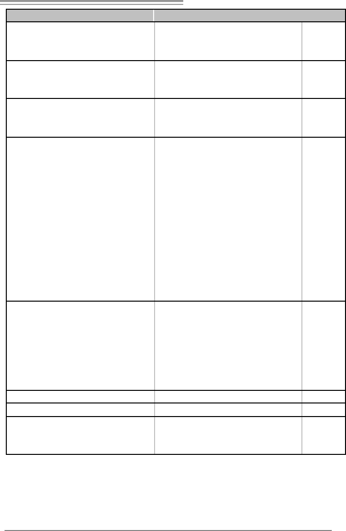
5.4 TROUBLESHOOTING
Probable Solution
1. No power to the system at all
Power light don’t illuminate, f an
inside power supply does not turn
on.
2. Indicator light on key board does
not turn on.
1. Make sure power cable is
securely plugged in.
2. Replace cable.
3. Contact technical support.
System inoperativ e. Keyboard lights
are on, power indicator lights are lit,
and hard driv e is spinning.
Using even pressure on both ends of
the DIMM, press down firmly until the
module snaps into place.
System does not boot from hard disk
driv e, can be booted f rom optical driv e.
1. Check cable running from disk to
disk controller board. Make sure
both ends are securely plugged
in ; c hec k t h e d r iv e ty pe in t he
standard CMOS setup.
2. Backing up the hard drive is
extremely important. All hard
disks are capable of breaking
down at any time.
System only boots f rom optical driv e.
Hard disk can be read and applications
can be used but booting from hard disk
is impossible.
1. Back up data and applications
files.
2. Ref ormat the hard driv e.
Re-install applications and data
using backup disks.
Screen message says “Invalid
Conf iguration” or “CMOS Failure.”
Rev iew system’s equipment. Make sur
e
correct inf ormation is in setup.
Cannot boot system after installing
second hard driv e.
1. Set master/slave jumpers
correctly.
2. Run SETUP program and select
correct driv e types. Call the drive
manuf acturers f or compatibility
with other drives.

P4M900-M7 FE/P4M890-M7 FE
25
This page is intentionally left blank.

Motherboard Manual
26
APPENDENCIES: SPEC IN OTHER LANGUAGE
GERMAN
P4M900-M7 FE P4M890-M7 FE
CPU
LGA 775
Intel Core2Duo/ Pentium 4 / Pentium D /
Celeron D / Celer on 4xx Prozes soren mit bis
zu 3, 8 GHz
*It is recommended to use
p
rocessors with
95W power co nsumption.
Unterstützt Hyper-Threading / Execute
Disable Bit
/
E nha nced I ntel S
p
ee dSte
p
®
/
Intel Architecture-64 / Extended Memory
64 Tech nolog y
FSB 533 / 80 0 / 1 06 6 MHz 533 / 80 0 / 1 06 6 MHz
Chipsatz VIA P4M900
VIA VT8237A
VIA P4M890
VIA VT8237A
Grafik
Chrome9 HC 3D / 2 D Grap hics
Max. 25 6MB gemei nsam be nutzter
Videospeicher
Chrome9 HC 3D / 2 D Grap hics
Max. 25 6MB gemei nsam be nutzter
Videospeicher
Super E/A
ITE 8712F
Bietet die häufi g verwe ndete n alte n Super
E/A-Funktio nen.
Low Pin C ount-Schnittstelle
Umgebungskontrolle,
Hardware-Überwachung
Lüfterdrehzahl-Controller
"Smart Guar dian" -Funktion v on ITE
ITE 8712F
Bietet die häufi g verwe ndete n alte n Super
E/A-Funktio nen.
Low Pin C ount-Schnittstelle
Umgebungskontrolle,
Hardware-Überwachung
Lüfterdrehzahl-Controller
"Smart Guar dian" -Funktion v on ITE
Arbeitsspe
icher
DDR2 DIMM-Steckplätze x 2
Unterstützt DDR2 533 / 667
Jeder DIMM unterstützt
256/512MB/1GB/2GB DDR2.
Max. 4GB Arbeitsspeicher
Ein-Kanal DDR2 S peichermod ul
registrierte DIMMs. ECC DIMMs werden
nicht unterstützt.
DDR2 DIMM-Steckplätze x 2
Unterstützt DDR2 533 / 667
Jeder DIMM unterstützt
256/512MB/1GB/2GB DDR2.
Max. 4GB Arbeitsspeicher
Ein-Kanal DDR2 S peichermod ul
registrierte DIMMs. ECC DIMMs werden
nicht unterstützt.
IDE
Integrierter IDE-Controller
Ultra DMA 33 / 66 / 100 / 133Bus
Master-Modus
Unterstützt PIO-Modus 0~4,
Integrierter IDE-Controller
Ultra DMA 33 / 66 / 100 / 133Bus
Master-Modus
Unterstützt PIO-Modus 0~4,
SATA
Integrierter Serial ATA-Controller
Datentransferr ate bis zu 1.5 Gb/s
Konform mit der SATA-S
p
ezifikation Version
1.0.
Integrierter Serial ATA-Controller
Datentransferr ate bis zu 1.5 Gb/s
Konform mit der SATA-S
p
ezifikation Version
1.0.

P4M900-M7 FE/P4M890-M7 FE
27
P4M900-M7 FE P4M890-M7 FE
LAN PHY
Realtek RTL 8201CL PHY
10 / 100 Mb/s A uto-Negotiation
Halb-/ Vollduplex-Funktion
Realtek RTL 8201CL PHY
10 / 100 Mb/s A uto-Negotiation
Halb-/ Vollduplex-Funktion
Audio-Cod
ec
ALC662
Unterstützt High-Definition Audio
5.1-Kanal-Au dioausg abe
ALC662
Unterstützt High-Definition Audio
5.1-Kanal-Au dioausg abe
PCI-Steckplatz x2 PCI-Steckplatz x2
PCI Expr ess x16 Steckplatz x1 PCI Expr ess x16 Steckplatz x1
Steckplätz
e PCI Expr ess x 1-Steckplatz x1 PCI Expr ess x 1-Steckplatz x1
Diskettenlaufwerkanschluss x1 Diskettenlaufwerkanschluss x1
Druckeranschluss Anschluss x1 Druckeranschluss Anschluss x1
IDE-Anschluss x2 IDE-Anschluss x2
SATA-Anschluss x2 SATA-Anschluss x2
Fronttafelanschluss x1 Fronttafelanschluss x1
Front-Audioanschluss x1 Front-Audioanschluss x1
CD-IN-Anschluss x1 CD-IN-Anschluss x1
CPU-Lüfter-Sockel x1 CPU-Lüfter-Sockel x1
System-Lüfter-Sockel x1 System-Lüfter-Sockel x1
"CMOS löschen"-Sockel x1 "CMOS löschen"-Sockel x1
USB-Anschluss x2 USB-Anschluss x2
Stromanschluss (24-polig) x1 Stromanschluss (24-polig) x1
Onboard-A
nschluss
Stromanschluss (4-polig) x1 Stromanschluss (4-polig) x1
Rückseiten
-E/A
PS/2-Tastatur x1
PS/2-Maus x1
Serieller Anschluss x1
VGA-Anschluss x1
LAN-Anschluss x1
USB-Anschluss x4
Audioanschluss x3
PS/2-Tastatur x1
PS/2-Maus x1
Serieller Anschluss x1
VGA-Anschluss x1
LAN-Anschluss x1
USB-Anschluss x4
Audioanschluss x3
Platinengr
öße. 190 mm (B) X 244 mm (L) 190 mm (B) X 244 mm (L)
Sonderfun
ktionen Unterstützt RAID 0 / 1 Unterstützt RAID 0 / 1
OS-Unters
tützung
Windows 2K / XP / VISTA
Biostar behält sich das Recht vor, ohne
Ankündigung die Unterstützung für ein
Betriebssystem hinz uzufü gen od er z u
entfernen.
Windows 2K / XP
Biostar behält sich das Recht vor, ohne
Ankündigung die Unterstützung für ein
Betriebssystem hinz uzufü gen od er z u
entfernen.

Motherboard Manual
28
FRANCE
P4M900-M7 FE P4M890-M7 FE
UC
LGA 775
Proc esseurs Intel Core 2Duo/ P entium 4 /
Pentium D / Celeron D / Celeron 4xx
j
us
q
u'à
3,8 G Hz
*It is recommended to use
p
rocessors with
95W power co nsumption.
Prend en charge les technologies
Hyper -Thre ading / d'ex écution de bit de
désactivation / Intel SpeedStep®
optimisée/ d'architecture Intel 64 / de
mémoire étendue 64
Bus frontal
533 / 80 0 / 1 06 6 MHz 533 / 80 0 / 1 06 6 MHz
Chipset VIA P4M900
VIA VT8237A
VIA P4M890
VIA VT8237A
Graphi que
s
Chrome9 HC 3D / 2 D Grap hics
Mémoire vidéo partagée maximale de 256
Mo
Chrome9 HC 3D / 2 D Grap hics
Mémoire vidéo partagée maximale de 256
Mo
Super E/S
ITE 8712F
Fournit la fo nc tionnalité de Super E/S
patrimoniales la plus utilisée.
Interface à faible compte de broc hes
Initiatives de contrôle environnementales,
Moniteur de matériel
Contrôleur de vitesse de ventilateur
Fonction "Gardien i ntelligent" de l'ITE
ITE 8712F
Fournit la fo nc tionnalité de Super E/S
patrimoniales la plus utilisée.
Interface à faible compte de broc hes
Initiatives de contrôle environnementales,
Moniteur de matériel
Contrôleur de vitesse de ventilateur
Fonction "Gardien i ntelligent" de l'ITE
Mémoire
principale
Fentes DDR 2 DIMM x 2
Prend en c harge la DDR 2 533 / 66 7
Chaque DIMM pren d e n ch arge des DDR2
de 256 Mo /512 Mo / 1Go / 2 Go
Capacité mémoire maximale de 4 Go
Module de mémoire DDR2 à mode à simple
voie
Les DIMM à registres et DIMM avec code
correcteurs d'erreurs ne sont
p
as
p
rises en
charge
Fentes DDR 2 DIMM x 2
Prend en c harge la DDR 2 533 / 66 7
Chaque DIMM pren d e n ch arge des DDR2
de 256 Mo /512 Mo / 1Go / 2 Go
Capacité mémoire maximale de 4 Go
Module de mémoire DDR2 à mode à simple
voie
Les DIMM à registres et DIMM avec code
correcteurs d'erreurs ne sont
p
as
p
rises en
charge
IDE
Contrôleur IDE intégr é
Mode
p
ri nci
p
ale de Bus Ultra DMA 33
/
66
/
100 / 13 3
Prend en charge le mode PIO 0~4,
Contrôleur IDE intégr é
Mode
p
ri nci
p
ale de Bus Ultra DMA 33
/
66
/
100 / 13 3
Prend en charge le mode PIO 0~4,
SATA
Contrôleur Serial ATA intégré
Taux de transfert jusqu'à 1.5 Go/s.
Conforme à la spécification SATA Version
1.0
Contrôleur Serial ATA intégré
Taux de transfert jusqu'à 1.5 Go/s.
Conforme à la spécification SATA Version
1.0

P4M900-M7 FE/P4M890-M7 FE
29
P4M900-M7 FE P4M890-M7 FE
LAN PHY
Realtek RTL 8201CL PHY
10 / 100 Mb/s négociation automatique
Half / Full duplex capability
Realtek RTL 8201CL PHY
10 / 100 Mb/s négociation automatique
Half / Full duplex capability
Codec
audio
ALC662
Prise en c harge de l'au dio haute dé finition
Sortie audio à 5.1 voies
ALC662
Prise en c harge de l'au dio haute dé finition
Sortie audio à 5.1 voies
Fente PCI x2 Fente PCI x2
Slot PCI Express x16 x1 Slot PCI Express x16 x1
Fentes
Slot PCI Ex press x 1 x1 Slot PCI Express x 1 x1
Connecteur de disqu ette x1 Connecteur de disqu ette x1
Connecteur de P ort d'imprimante x1 Connecteur de P ort d'imprimante x1
Connecteur IDE x2 Connecteur IDE x2
Connecteur SATA x2 Connecteur SATA x2
Connecteur du pa nne au avant x1 Connecteur du pa nne au avant x1
Connecteur Audio d u p ann eau ava nt x1 Connec teur Audio du p ann eau ava nt x1
Connecteur d'entré e CD x1 Connecteur d'entré e CD x1
Embase d e ve ntilateur UC x1 Embase d e ve ntilateur UC x1
Embase de ventilateur système x1 Embase de ventilateur système x1
Embase d'e ffacement CMOS x1 Embase d'e ffacement CMOS x1
Connecteur USB x2 Connecteur USB x2
Connecteur d'alimentatio n x1
(24 broches)
Connecteur d'alimentatio n x1
(24 broches)
Connecteu
r
embarqué
Connecteur d'alimentatio n x1
(4 br oches)
Connecteur d'alimentatio n x1
(4 br oches)
E/S d u
pann eau
arrière
Clavier PS/2 x1
Souris PS/2 x1
Port série x1
Port VGA x1
Port LAN x1
Port USB x4
Fiche audio x3
Clavier PS/2 x1
Souris PS/2 x1
Port série x1
Port VGA x1
Port LAN x1
Port USB x4
Fiche audio x3
Dimension
s de la
carte
190 mm (l) X 244 mm (H) 190 mm (l) X 244 mm (H)
Fonc tionna
lités
spéciales
Prise en c harge RAID 0 / 1 Prise en c harge RAID 0 / 1
Support
SE
Windows 2K / XP / VISTA
Biostar se réserve le droit d'ajo uter ou de
supprimer le support de SE avec o u sa ns
préavis.
Windows 2K / XP
Biostar se réserve le droit d'ajo uter ou de
supprimer le support de SE avec o u sa ns
préavis.

Motherboard Manual
30
ITALIAN
P4M900-M7 FE P4M890-M7 FE
CPU
LGA 775
Processore Intel Core2Duo/ Pentium 4 /
Pentium D / Celeron D / Celeron 4xx fi no a
3.8 G Hz
*It is recommended to use processors with
95W power co nsumption.
Supporto di Hyper -T hreadi ng / Execute
Disable Bit
/
E nha nced I ntel S
p
ee dSte
p
®
/
Architettura Intel 64
/
Tecnolo
g
ia Extended
Memory 64
LGA 775
Processore Intel Core2Duo/ Pentium 4 /
Pentium D / Celeron D / Celeron 4xx fi no a
3.8 G Hz
*It is recommended to use
p
rocessors with
95W power co nsumption.
Supporto di Hyper -T hreadi ng / Execute
Disable Bit
/
E nha nced I ntel S
p
ee dSte
p
®
/
Architettura Intel 64
/
Tecnolo
g
ia Extended
Memory 64
FSB 533 / 80 0 / 1 06 6 MHz 533 / 80 0 / 1 06 6 MHz
Chipset VIA P4M900
VIA VT8237A
VIA P4M890
VIA VT8237A
Grafica
Chrome9 HC 3D / 2 D Grap hics
La memoria vi deo condivisa massima è di
256MB
Chrome9 HC 3D / 2 D Grap hics
La memoria vi deo condivisa massima è di
256MB
Super I/O
ITE 8712F
Fornisce le funzionalità legacy Super I/O
usate più comunemente.
Interfaccia LPC (L ow Pin Count)
Funzioni di controllo dell’ambiente:
Monitoraggio hardware
Controller velocità ventolina
Funzione "Smart G uardi an" di I TE
ITE 8712F
Fornisce le funzionalità legacy Super I/O
usate più comunemente.
Interfaccia LPC (L ow Pin Count)
Funzioni di controllo dell’ambiente:
Monitoraggio hardware
Controller velocità ventolina
Funzione "Smart G uardi an" di I TE
Memoria
principale
Alloggi DIMM DDR 2 x 2
Supporto di DDR2 533 / 667
Ciascun DIMM su pporta DDR 2 25 6MB /
512MB / 1GB / 2 GB
Capacità massima della memoria 4GB
Modulo di memoria DDR2 a can ale sin golo
DIMM registrati e DIMM ECC non sono
supportati
Alloggi DIMM DDR 2 x 2
Supporto di DDR2 533 / 667
Ciascun DIMM su pporta DDR 2 25 6MB /
512MB / 1GB / 2 GB
Capacità massima della memoria 4GB
Modulo di memoria DDR2 a can ale sin golo
DIMM registrati e DIMM ECC non sono
supportati
IDE
Controller IDE i ntegrato
Modalità Bus Master Ultra DMA 33 / 66 /
100 / 1 33
Supporto modalità PIO Mode 0- 4
Controller IDE i ntegrato
Modalità Bus Master Ultra DMA 33 / 66 /
100 / 1 33
Supporto modalità PIO Mode 0- 4
SATA
Controller Serial ATA integrato
Velocità di trasferimento dei dati fi no a 1.5
Gb/s.
Compatibile specifiche SATA Versione 1.0.
Controller Serial ATA integrato
Velocità di trasferimento dei dati fi no a 1.5
Gb/s.
Compatibile specifiche SATA Versione 1.0.

P4M900-M7 FE/P4M890-M7 FE
31
P4M900-M7 FE P4M890-M7 FE
LAN PHY
Realtek RTL 8201CL PHY
Negoziazione automatica 10 / 10 0 Mb /s
Capacità Half / Full Duplex
Realtek RTL 8201CL PHY
Negoziazione automatica 10 / 10 0 Mb /s
Capacità Half / Full Duplex
Codec
audio
ALC662
Supporto audio High-Definition (HD)
Uscita audio 5.1 canali
ALC662
Supporto audio High-Definition (HD)
Uscita audio 5.1 canali
Alloggio PCI x2 Alloggio PCI x2
Alloggio PCI Ex press x1 6 x1 Alloggio PCI Ex press x1 6 x1
Alloggi
Alloggio PCI Ex press x1 x1 Alloggio PCI Ex press x1 x1
Connettore flo ppy x1 Connettore flo ppy x1
Connettore Porta stampa nte x1 Connettore Porta stampa nte x1
Connettore IDE x2 Connettore IDE x2
Connettore SATA x2 Connettore SATA x2
Connettore pa nnello fro ntale x1 Connettore pa nnello fro ntale x1
Connettore audio frontale x1 Connettore audio frontale x1
Connettore CD-in x1 Connettore CD-in x1
Collettore ventolina CPU x1 Collettore ventolina CPU x1
Collettore ventolina sistema x1 Collettore ventolina sistema x1
Collettore cancellazione CMOS x1 Collettore cancellazione CMOS x1
Connettore USB x2 Connettore USB x2
Connettore alimentazione x1
(24 pin)
Connettore alimentazione x1
(24 pin)
Connettori
su scheda
Connettore alimentazione x1
(4 pi n)
Connettore alimentazione x1
(4 pi n)
I/O
pannello
posteriore
Ta s t i e r a P S / 2 x 1
Mouse PS/2 x1
Porta seriale x1
Porta VGA x1
Porta LAN x1
Porta USB x4
Connettore au dio x3
Ta s t i e r a P S / 2 x 1
Mouse PS/2 x1
Porta seriale x1
Porta VGA x1
Porta LAN x1
Porta USB x4
Connettore au dio x3
Dimension
i scheda 190 mm (lar ghezza) x 244 mm (altezza) 190 mm (lar ghezza) x 244 mm (altezza)
Caratterist
iche
speciali
Supporto RAID 0 / 1 Supporto RAID 0 / 1
Sistemi
operativi
supportati
Windows 2K / XP / VISTA
Biostar si riserva il diritto di aggiungere o
rimuovere il supporto di qualsiasi sistema
operativo se nza pre avviso.
Windows 2K / XP
Biostar si riserva il diritto di aggiungere o
rimuovere il supporto di qualsiasi sistema
operativo se nza pre avviso.

Motherboard Manual
32
SPANISH
P4M900-M7 FE P4M890-M7 FE
CPU
LGA 775
Procesador I ntel Core 2Duo / Penti um 4 /
Pentium D / Celeron D / Celeron 4xx hasta
3,8 G Hz
*It is recommended to use
p
rocessors with
95W power co nsumption.
Admite Hyper -T hreadi ng / Bit d e
deshabilitación de ejecución / Intel
SpeedStep® Mejora do / Intel
Architecture-64 / Tecnología Extended
Memory 64
FSB 533 / 80 0 / 1 06 6 MHz 533 / 80 0 / 1 06 6 MHz
Conjunto
de chips
VIA P4M900
VIA VT8237A
VIA P4M890
VIA VT8237A
Gráficos
Chrome9 HC 3D / 2 D Grap hics
Memoria máxima de vídeo compartida de
256MB
Chrome9 HC 3D / 2 D Grap hics
Memoria máxima de vídeo compartida de
256MB
Súper E/S
ITE 8712F
Le ofrece las funcionalidades heredadas de
uso más común Súper E/S.
Interfaz de cuenta Low Pin
Iniciativas de control de entorno,
Monitor hardware
Controlador de velocida d d e ve ntilador
Función "Guardia inteligente" de ITE
ITE 8712F
Le ofrece las funcionalidades heredadas de
uso más común Súper E/S.
Interfaz de cuenta Low Pin
Iniciativas de control de entorno,
Monitor hardware
Controlador de velocida d d e ve ntilador
Función "Guardia inteligente" de ITE
Memoria
principal
Ranuras DIMM DDR 2 x 2
Admite DDR2 de 533 / 667
Cada DIMM admite DDR de 256MB
/
51 2MB
/1GB / 2GB
Capacidad máxima de memoria de 4GB
Módulo de memoria DDR 2 de canal Sencillo
No admite DIMM registrados o DIMM
compatibles con ECC
Ranuras DIMM DDR 2 x 2
Admite DDR2 de 533 / 667
Cada DIMM admite DDR de 256MB
/
51 2MB
/1GB / 2GB
Capacidad máxima de memoria de 4GB
Módulo de memoria DDR 2 de canal Sencillo
No admite DIMM registrados o DIMM
compatibles con ECC
IDE
Controlador IDE integrado
Modo bus maestro Ultra DMA 33 / 66 / 100
/ 133
Soporte los Mo dos PIO 0~4,
Controlador IDE integrado
Modo bus maestro Ultra DMA 33 / 66 / 100
/ 133
Soporte los Mo dos PIO 0~4,
SATA
Controlador ATA Serie Integrado
Tasas de transferencia de hasta 1.5 Gb/s.
Compatible con la versión SATA 1.0.
Controlador ATA Serie Integrado
Tasas de transferencia de hasta 1.5 Gb/s.
Compatible con la versión SATA 1.0.

P4M900-M7 FE/P4M890-M7 FE
33
P4M900-M7 FE P4M890-M7 FE
Red Local
Realtek RTL 8201CL PHY
Negociación de 10 / 10 0 Mb/s
Funciones Half / Full dúplex
Realtek RTL 8201CL PHY
Negociación de 10 / 10 0 Mb/s
Funciones Half / Full dúplex
Códecs de
sonido
ALC662
Soporte d e soni do de Alta Defi nición
Salida de sonido de 5.1 canales
ALC662
Soporte d e soni do de Alta Defi nición
Salida de sonido de 5.1 canales
Ranura PCI X2 Ranura PCI X2
Ranura PCI Ex press x16 X1 Ranura PCI Ex press x1 6 X1
Ranuras
Ranura PCI ex press x 1 X1 Ranura PCI ex press x 1 X1
Conector disco flexible X1 Conector disco flexible X1
Conector Puerto de impresora X1 Conector Puerto de impresora X1
Conector IDE X2 Conector IDE X2
Conector SATA X2 Conector SATA X2
Conector de pa nel fro ntal X1 Conector de pa nel fro ntal X1
Conector de sonido frontal X1 Conector de sonido frontal X1
Conector de entra da de C D X1 Conector de entra da de C D X1
Cabecera de ve ntilador de C PU X1 Cabecera d e ve ntilador de C PU X1
Cabecera de ve ntilador de
sistema X1
Cabecera de ve ntilador de
sistema X1
Cabecera de b orrado de CMO S X1 Cabecera d e b orrado de CMOS X1
Conector USB X2 Conector USB X2
Conector de alimentación X1
(24 patillas)
Conector de alimentación X1
(24 patillas)
Conectore
s en placa
Conector de alimentación X1
(4 patillas)
Conector de alimentación X1
(4 patillas)
Panel
trasero de
E/S
Te c l a d o P S / 2 X 1
Ratón PS/2 X1
Puerto serie X1
Puerto VGA X1
Puerto de re d local X1
Puerto USB X4
Conector de sonido X3
Te c l a d o P S / 2 X 1
Ratón PS/2 X1
Puerto serie X1
Puerto VGA X1
Puerto de re d local X1
Puerto USB X4
Conector de sonido X3
Ta m año de
la placa 190mm. (A) X 244 Mm. (H) 190mm. (A) X 244 Mm. (H)
Funciones
especiales Admite RAID 0 / 1 Admite RAID 0 / 1
So
p
orte de
sistema
operativo
Windows 2K / XP / VISTA
Biostar se reserva el derecho de añadir o
retirar el so
p
orte de cual
q
uier SO con o sin
aviso previo.
Windows 2K / XP
Biostar se reserva el derecho de añadir o
retirar el so
p
orte de cual
q
uier SO con o sin
aviso previo.

Motherboard Manual
34
PORTUGUESE
P4M900-M7 FE P4M890-M7 FE
CPU
LGA 775
Processador Intel Core2Duo/ Pe ntium 4 /
Pentium D / Celeron D / Celer on 4xx até 3
,
8
GHz
*It is recommended to use
p
rocessors with
95W power co nsumption.
Suporta as tecnologias Hyper -Threa ding /
Execute Disable Bit / Enha nced I ntel
SpeedStep® / Intel Arquitecture -64 /
Extende d Memor y 64
FSB 533 / 80 0 / 1 06 6 MHz 533 / 80 0 / 1 06 6 MHz
Chipset VIA P4M900
VIA VT8237A
VIA P4M890
VIA VT8237A
Placa
gráfica
Chrome9 HC 3D / 2 D Grap hics
Memória de vídeo máxima partilhada: 256
MB
Chrome9 HC 3D / 2 D Grap hics
Memória de vídeo máxima partilhada: 256
MB
Especificaç
ão Super
I/O
ITE 8712F
Proporciona as funcionalidades mais
utilizadas em termos da especificação
Super I/O.
Interface LPC (Low Pi n Co unt).
Iniciativas para control o do am biente
Monitorização do hardware
Controlador da velocida de da v entoin ha
Função "Smart Guardia n" da I TE
ITE 8712F
Proporciona as funcionalidades mais
utilizadas em termos da especificação
Super I/O.
Interface LPC (Low Pi n Co unt).
Iniciativas para control o do am biente
Monitorização do hardware
Controlador da velocida de da v entoin ha
Função "Smart Guardia n" da I TE
Memória
principal
Ranhuras DIMM D DR2 x 2
Suporta módulos DDR2 533 / 667
Cada mó dulo DIMM suporta uma memória
DDR2 de 256MB /512 MB / 1 GB / 2GB
Capacidade máxima de memória : 4 GB
Módulo de memória DDR2 de canal simples
Os módulos DIMM registados e os DIMM
ECC não são suportados
Ranhuras DIMM D DR2 x 2
Suporta módulos DDR2 533 / 667
Cada mó dulo DIMM suporta uma memória
DDR2 de 256MB /512 MB / 1 GB / 2GB
Capacidade máxima de memória : 4 GB
Módulo de memória DDR2 de canal simples
Os módulos DIMM registados e os DIMM
ECC não são suportados
IDE
Controlador IDE integrado
Modo Bus master Ultra DMA 33 / 6 6 / 10 0
/
133
Suporta o mod o PIO 0~4,
Controlador IDE integrado
Modo Bus master Ultra DMA 33 / 6 6 / 10 0
/
133
Suporta o mod o PIO 0~4,
SATA
Controlador Serial ATA integrado
Velocidades de transmissão de dados até
1.5 G b/s.
Compatibilidade com a especificação SATA
versão 1.0.
Controlador Serial ATA integrado
Velocidades de transmissão de dados até
1.5 G b/s.
Compatibilidade com a especificação SATA
versão 1.0.

P4M900-M7 FE/P4M890-M7 FE
35
P4M900-M7 FE P4M890-M7 FE
LAN PHY
Realtek RTL 8201CL PHY
Auto ne goc iaç ão de 10 / 10 0 MB/s
Capacidade semi/full- duplex
Realtek RTL 8201CL PHY
Auto ne goc iaç ão de 10 / 10 0 MB/s
Capacidade semi/full- duplex
Codec de
som
ALC662
Suporta a especificação High-Definition
Audio
Saída de á udio de 5.1 ca nais
ALC662
Suporta a especificação High-Definition
Audio
Saída de á udio de 5.1 ca nais
Ranhura PCI x2 Ranhura PCI x2
Ranhura PCI Express x 16 x1 Ranhura PCI Express x 16 x1
Ranhuras
Ranhura PCI Express x 1 x1 Ranhura PCI Express x 1 x1
Conector da unida de de disquetes x 1 Conector da unida de de disquetes x 1
Conector da para impressora x1 Conector da para impressora x1
Conector IDE x2 Conector IDE x2
Conector SATA x2 Conector SATA x2
Conector do pai nel fro ntal x1 Conector do pai nel fro ntal x1
Conector de áu dio fro ntal x1 Conector de áu dio fro ntal x1
Conector para e ntrada de C Ds x1 Conector para e ntrada de C Ds x1
Conector da ve ntoinh a d a CPU x1 Conector da ve ntoinh a d a CPU x1
Conector da ve ntoinha d o
sistema x1
Conector da ve ntoinha d o
sistema x1
Conector para limpeza do CMO S x1 Conector para limpeza do CMOS x1
Conector USB x2 Conector USB x2
Conector de alimentação x1
(24 pinos)
Conector de alimentação x1
(24 pinos)
Conectore
s na placa
Conector de alimentação x1
(4 pi nos)
Conector de alimentação x1
(4 pi nos)
Entradas/
Saídas no
painel
traseiro
Te c l a d o P S / 2 x 1
Rato PS/2 x1
Porta série x1
Porta VGA x1
Porta LAN x1
Porta USB x4
Tomada de áu dio x3
Te c l a d o P S / 2 x 1
Rato PS/2 x1
Porta série x1
Porta VGA x1
Porta LAN x1
Porta USB x4
Tomada de áu dio x3
Ta m a n h o
da pl aca 19 0 mm (L) X 24 4 mm (A) 19 0 mm (L) X 24 4 mm (A)
Característ
icas
especiais
Suporta as funções RAID 0 / 1 Suporta as funções RAID 0 / 1
Sistemas
operativos
suportado
s
Windows 2K / XP / VISTA
A Biostar reserva-se o direito de adicionar
ou remover suporte para qualquer sistema
operativo com ou sem aviso prévio.
Windows 2K / XP
A Biostar reserva-se o direito de adicionar
ou remover suporte para qualquer sistema
operativo com ou sem aviso prévio.

Motherboard Manual
36
POLISH
P4M900-M7 FE P4M890-M7 FE
Procesor
LGA 775
Procesor Intel Cor e2Duo/ Penti um 4 /
Pentium D / Celeron D / Celeron 4xx do 3
,
8
GHz
*It is recommended to use processors with
95W power co nsumption.
Obsługa Hyper-Threadin
g
/
Exec ute Disable
Bit / Enhanced Intel SpeedStep® / Intel
Architecture-64 / Extended Memory 64
Technol ogy
LGA 775
Procesor Intel Cor e2Duo/ Penti um 4 /
Pentium D / Celeron D / Celeron 4xx do 3
,
8
GHz
*It is recommended to use processors with
95W power co nsumption.
Obsługa Hyper-Threadin
g
/
Exec ute Disable
Bit / Enhanced Intel SpeedStep® / Intel
Architecture-64 / Extended Memory 64
Technol ogy
FSB 533 / 80 0 / 1 06 6 MHz 533 / 80 0 / 1 06 6 MHz
Chipset VIA P4M900
VIA VT8237A
VIA P4M890
VIA VT8237A
Grafika
Chrome9 HC 3D / 2 D Grap hics
Maks. wielkość współdzielonej pamięci
video wy nos i 256MB
Chrome9 HC 3D / 2 D Grap hics
Maks. wielkość współdzielonej pamięci
video wy nos i 256MB
Pamięć
główna
Gniazda DDR 2 DIMM x 2
Obsługa D DR2 53 3 / 6 67
Każde gniazd o DIMM obsługuje moduły
256MB /5 12MB / 1GB / 2GB D DR2
Maks. wielkość pamięci 4GB
Moduł pamięci DDR2 z trybem
poje dynczego kan ału
Brak obsługi Registered DIMM or az ECC
DIMM
Gniazda DDR 2 DIMM x 2
Obsługa D DR2 53 3 / 6 67
Każde gniazd o DIMM obsługuje moduły
256MB /5 12MB / 1GB / 2GB D DR2
Maks. wielkość pamięci 4GB
Moduł pamięci DDR2 z trybem
poje dynczego kan ału
Brak obsługi Registered DIMM or az ECC
DIMM
Super I/O
ITE 8712F
Zapewnia naj bardziej powszechne f unkcje
Super I/O.
Interfejs Low Pin Count
Funkcje kontroli warun ków prac y,
Monitor H/W
Kontroler prędkości wentylatora
Funkcja ITE "Smart Guar dian"
ITE 8712F
Zapewnia naj bardziej powszechne f unkcje
Super I/O.
Interfejs Low Pin Count
Funkcje kontroli warun ków prac y,
Monitor H/W
Kontroler prędkości wentylatora
Funkcja ITE "Smart Guar dian"
IDE
Zintegrowany kontroler ID E
Ultra DMA 33 / 66 / 100 / 133 Tryb Bus
Master
obsługa PIO tryb 0~4,
Zintegrowany kontroler ID E
Ultra DMA 33 / 66 / 100 / 133 Tryb Bus
Master
obsługa PIO tryb 0~4,
SATA
Zintegrowany kontroler Serial ATA
Transfer danych do 1.5 Gb/s.
Zgodność ze specyfikacją SATA w wersji
1.0.
Zintegrowany kontroler Serial ATA
Transfer danych do 1.5 Gb/s.
Zgodność ze specyfikacją SATA w wersji
1.0.

P4M900-M7 FE/P4M890-M7 FE
37
P4M900-M7 FE P4M890-M7 FE
LAN PHY
Realtek RTL 8201CL PHY
10 / 100 Mb/s z automatyczną neg ocjacją
szybkości
Działanie w trybie połowicznego / pełnego
dupleksu
Realtek RTL 8201CL PHY
10 / 100 Mb/s z automatyczną neg ocjacją
szybkości
Działanie w trybie połowicznego / pełnego
dupleksu
Kodek
dźwiękowy
ALC662
Obsługa Hi gh-Definition Audio
5.1 ka nałowe wy jście audio
ALC662
Obsługa Hi gh-Definition Audio
5.1 ka nałowe wy jście audio
Gniazdo PCI x2 Gniazdo PCI x2
Gniazdo PCI Express x16 x1 Gniazdo PCI Express x16 x1 Gniazda
Gniazdo PCI Express x 1 x1 Gniazdo PCI Express x 1 x1
Złącze napędu dyskietek x1 Złącze napędu dyskietek x1
Złącze Port drukarki x1 Złącze Port druk arki x1
Złącze IDE x2 Złącze IDE x2
Złącze SATA x2 Złącze SATA x2
Złącze panela przed niego x1 Złącze panela przed niego x1
Przednie złącze a udio x1 Przednie złącze audio x1
Złącze wejścia CD x1 Złącze wejścia CD x1
Złącze główkowe wentylatora
procesora x1
Złącze główkowe wentylatora
procesora x1
Złącze główkowe wentylatora
systemowego x1
Złącze główkowe wentylatora
systemowego x1
Złącze główkowe kasowani a
CMOS x1
Złącze główkowe kasowani a
CMOS x1
Złącze USB x2 Złącze USB x2
Złącz e zasilania (2 4 pi nowe) x1 Złącze zas ilania (24 pi nowe) x1
Złącza
wbudowan
e
Złącze zasilania (4 pinowe) x1 Złącze zasilania (4 pinowe) x1
Back Panel
I/O
Klawiatura PS/2 x1
Mysz PS/2 x1
Port szeregowy x1
Port VGA x1
Port LAN x1
Port USB x4
Gniazdo audio x3
Klawiatura PS/2 x1
Mysz PS/2 x1
Port szeregowy x1
Port VGA x1
Port LAN x1
Port USB x4
Gniazdo audio x3
Wymiary
płyty 190 mm (S) X 244 mm (W) 190 mm (S) X 244 mm (W)
Funkcje
specjalne Obsługa RAID 0 / 1 Obsługa RAID 0 / 1
Obsluga
systemu
operacyjn
ego
Windows 2K / XP / VISTA
Biostar zastrzega sobie prawo do dawania
lub odwoływania obsługi dowolnego
systemu operacyj nego bez powiad omienia.
Windows 2K / XP
Biostar zastrzega sobie prawo do dawania
lub odwoływania obsługi dowolnego
systemu operacyj nego bez powiad omienia.

Motherboard Manual
38
RUSSIAN
P4M900-M7 FE P4M890-M7 FE
CPU
(ц ентра льны
й
проц есс ор)
LGA 775
Процессор Intel Core 2Du o/ Pe ntium 4 /
Pentium D / Celeron D / Celeron 4xx до
3.8 ГГц
*It is recommended to use processors
with 95W power cons umption.
Подде рж ка техн оло гий Hyper-Threading
/ Execute Disable Bit / En hance d Intel
SpeedStep® / Intel Architecture-64 /
Extende d Memor y 64 Tech nolog y
LGA 775
Процессор Intel Core 2Duo/ Pe ntium 4 /
Pentium D / Celeron D / Celeron 4xx до
3.8 ГГц
*It is recommended to use processors
with 95W power cons umption.
Подде рж ка техн оло гий Hyper-Threading
/ Execute Disable Bit / En hance d Intel
SpeedStep® / Intel Architecture-64 /
Extende d Memor y 64 Tech nolog y
FSB 533 / 80 0 / 1 06 6 МГц 533 / 80 0 / 1 06 6 МГц
Набор
микросхем
VIA P4M900
VIA VT8237A
VIA P4M890
VIA VT8237A
Графика
Chrome9 HC 3D / 2 D Grap hics
Максимальная совмес тно исп ользуемая
видео память составляет 256 МБ
Chrome9 HC 3D / 2 D Grap hics
Максимальная совмес тно исп ользуемая
видео память составляет 256 МБ
Основная
память
Слоты DDR2 DIMM x 2
Подде рж ка DDR2 533 / 667
Каждый модуль DIMM по ддерж ивае т
256MB / 51 2МБ / 1ГБ / 2ГБ DDR2
Максимальная ёмк ость памя ти 4 ГБ
Модуль памя ти с од нока наль ны м
реж имом DDR2
Не п одде рживае т з а рег истр иров ан ны е
модули DIMM and ECC DIMM
Слоты DDR2 DIMM x 2
Подде рж ка DDR2 533 / 667
Каждый модуль DIMM по ддерж ивае т
256MB / 51 2МБ / 1ГБ / 2ГБ DDR2
Максимальная ёмк ость памя ти 4 ГБ
Модуль памя ти с од нока наль ны м
реж имом DDR2
Не п одде рживае т з а рег истр иров ан ны е
модули DIMM and ECC DIMM
Super I/O
ITE 8712F
Обеспечива ет на ибо лее ис по льз уемы е
действ ующие функциональные
возможности Super I/O.
Инте рфейс с низким количеством
выводов
Иниц иа ти вы по охр ане ок руж ающей
среды,
А ппара тны й монитор
Регуля тор скор ости
Функция IT E "Smart Guardian"
(Интелле ктуа льна я защита)
ITE 8712F
Обеспечива ет на ибо лее ис по льз уемы е
действ ующие функциональные
возможности Super I/O.
Инте рфейс с низким количеством
выводов
Иниц иа ти вы по охр ане ок руж ающей
среды,
А ппара тны й монитор
Регуля тор скор ости
Функция IT E "Smart Guardian"
(Интелле ктуа льна я защита)
IDE
Встроенное устр ойств о управления
вс трое нны ми ин терфе йсами устройств
Режим "хозяина" шины Ultra DMA 33
/
66
/ 1 00 / 133
Подде рж ка режима PIO 0~4,
Встроенное устр ойств о управления
вс трое нны ми ин терфе йсами устройств
Режим "хозяина" шины Ultra DMA 33
/
66
/ 1 00 / 133
Подде рж ка режима PIO 0~4,
SATA
Встроенное посл едов ате льное
устройс тво управле ния ATA
скорость пер едач и данных до 1.5
гига бит/с.
Соотве тств ие с п ец ификац и и SATA
версия 1.0.
Встроенное посл едов ате льное
устройс тво управле ния ATA
скорость пер едач и данных до 1.5
гига бит/с.
Соотве тств ие с п ец ификац и и SATA
версия 1.0.

P4M900-M7 FE/P4M890-M7 FE
39
P4M900-M7 FE P4M890-M7 FE
Локаль ная
сеть
Realtek RTL 8201CL PHY
Автоматическое согласование 10 / 100
Мб/с
Частичная / пол ная дуп лексна я
способнос ть
Realtek RTL 8201CL PHY
Автоматическое согласование 10 / 100
Мб/с
Частичная / пол ная дуп лексна я
способнос ть
Звуково й
кодек
ALC662
Звукова я поддержка High-Definition
5.1кана льны й звуков ой выход
ALC662
Звукова я поддержка High-Definition
5.1кана льны й звуков ой выход
Слот PCI x2 Слот PCI x2
Слот PCI Express x16 x1 Слот PCI Express x16 x1
Слоты
Слот PCI Express x 1 x1 Слот PCI Ex press x 1 x1
Разъём НГМД x1 Разъём НГМД x1
Разъём Пор т под ключе ния
при нте ра x1
Разъём Пор т под ключе ния
при нте ра x1
Разъём IDE x2 Разъём IDE x2
Разъём SATA x2 Разъём SATA x2
Разъём на лицево й пане ли x1 Разъём на лицево й пане ли x1
Входной звук овой раз ъём x1 Входной звук овой раз ъём x1
Разъём вв ода дл я CD x1 Разъём вв ода дл я CD x1
Контактирующее
прис пос обл ени е ве нтиля тора
ц ентра льно го проц ес сора x1
Контактирующее
прис пос обл ени е ве нтиля тора
ц ентра льно го проц ес сора x1
Контактирующее п риспос о бле ние
вентиля тор а системы x1
Контактирующее п риспос о бле ние
вентиля тор а системы x1
Открытое кон так тир ующее
прис пос обл ени е CMOS x1
Открытое кон так тир ующее
прис пос обл ени е CMOS x1
USB-разъём x2 USB-разъём x2
Разъем пит ан ия (24 вывод) x1 Разъем пит ан ия (24 вывод) x1
Встроенный
разъём
Разъем пит ан ия (4 вывод) x1 Разъем пит ан ия (4 вывод) x1
Задн яя
пане ль
средств
ввода-выво д
а
Клавиатура PS/ 2 x1
Мышь PS/2 x1
Последо вате льный по рт x1
Порт VGA x1
Порт LAN x1
USB-порт x4
Гнездо для по дклю ч ени я
наушн иков x3
Клавиатура PS/ 2 x1
Мышь PS/2 x1
Последо вате льный по рт x1
Порт VGA x1
Порт LAN x1
USB-порт x4
Гнездо для по дклю ч ени я
наушн иков x3
Размер
пане ли 190 мм (Ш) X 24 4 мм (В) 190 мм (Ш) X 244 мм (В)
Специальны
е
техн ические
харак тер ист
ики
Подде рж ка RAID 0 / 1 Подде ржка RAID 0 / 1
Подде рж ка
OS
Windows 2K / XP / VISTA
Biostar сохраняет за собой прав о
добав лять или уда лять средс тва
обеспече ни я для OS с ил и без
пред вар ите льно го уведомления.
Windows 2K / XP
Biostar сохраняет за собой прав о
добав лять или уда лять средс тва
обеспече ни я для OS с ил и без
пред вар ите льно го уведомления.

Motherboard Manual
40
ARABIC
P4M900-M7 FE P4M890-M7 FE
ةﺪﺣو ﺔﺠﻟﺎﻌﻤﻟا
ﺔ ﻳﺰآﺮﻤﻟا
LGA 775
تﺎﺠﻟﺎﻌﻡIntel Core2Duo
/
Pe ntium 4
/
Pentium
D / C eleron D / Celer on 4xx ﺑ ددﺮﺘ ﻳ ﻰﻟإ ﻞﺼ8.3
ﺰﺕﺮه ﺎﺠﻴﺝ
*It is recommended to use
p
rocessors with
95W power co nsumption.
تﺎﻴﻨﻘﺕ ﻢﻋﺪﺕHyper -Thre adin
g
/
Exec ute Disabl e
Bit / En hance d I ntel S
p
ee dSte
p
®
/
Extende d Memor y 64 Tech nolog y
LGA 775
تﺎﺠﻟﺎﻌﻡIntel Core2Duo
/
Pe ntium 4
/
Pentium
D / C eleron D / Celer on 4xx ﺑ ددﺮﺘ ﻳ ﻰﻟإ ﻞﺼ8.3
ﺰﺕﺮه ﺎﺠﻴﺝ
*It is recommended to use processors with
95W power co nsumption.
تﺎﻴﻨﻘﺕ ﻢﻋﺪﺕHyper -Thre adin
g
/
Exec ute Disabl e
Bit
/
En hance d I ntel S
p
ee dSte
p
®
/
Extende d Memor y 64 Tech nolog y
ﻞﻗﺎﻨﻟا ﻲﻡﺎﻡﻷا
ﻲﺒﻥﺎﺠﻟا
ددﺮﺕ 533 / 800 / 10 66 ﺰﺕﺮه ﺎﺠﻴﻡ
ددﺮﺕ 533 / 800 / 10 66 ﺰﺕﺮه ﺎﺠﻴﻡ
ﺔﻋﻮﻤﺠﻡ ﺢﺋاﺮﺸﻟا
VIA P4M900
VIA VT8237A
VIA P4M890
VIA VT8237A
ﺎﻡﻮﺳﺮﻟا ﺔﻗﺎﻄﺑت
Chrome9 HC 3D / 2 D Grap hics
ﺔآﺮﺘﺸﻤﻟا ﻮﻳﺪﻴﻔﻟا ةﺮآاﺬﻟ ﺔﻌﺳ ﻰﺼﻗأ256 ﺖﻳ ﺎ ﺑ ﺎﺠﻴﻡ
Chrome9 HC 3D / 2 D Grap hics
ﺔآﺮﺘﺸﻤﻟا ﻮﻳﺪﻴﻔﻟا ةﺮآاﺬﻟ ﺔﻌﺳ ﻰﺼﻗأ256 ﺖﻳ ﺎ ﺑ ﺎﺠﻴﻡ
ةﺮآاﺬﻟا ﺔﻴﺴﻴﺋﺮﻟا
ﺔﺤﺘ ﻓDDR2 DIMM دﺪﻋ2
ﻢﻋﺪﺕ ةﺮآاﺬﻟا ﻦﻡ عﻮﻥ DDR2 تﺎﻌﺳ 533 / 667 ﺎﺠﻴﻡ ﺖﻳ ﺎﺑ
ﻢﻋﺪﺕ ﻞآ ﺔﺤﺘﻓ DIMM ﻢﻋﺪﺕ ةﺮآاذ ﻦﻡ عﻮﻥ DDR2 ﺔﻌﺳ
256 ﺎﺠﻴﻡ ﺖﻳ ﺎ ﺑ /512 ﺎﺠﻴﻡ ﺖﻳﺎﺑ و1 ﺎﺠﻴﺝ ﺖﻳﺎﺑ / 2 ﺎﺠﻴﺝ
ﺖﻳﺎﺑ
ﺔﻌﺳ ةﺮآاذ ىﻮﺼﻗ 4 ﺎﺠﻴﺝ ﺖﻳ ﺎ ﺑ
ةﺪﺣو ةﺮآ اذ DDR2 ﺔﻳدﺎﺣأ ةﺎﻨﻘﻟا
ةﺮآاﺬﻟا ﻖﺋﺎﻗر ﻢﻋﺪﺕ ﻻDIMM ﻊﻡ ﻖﻓاﻮﺘﺕ ﻻ ﻲﺘﻟا ﻚﻠﺕو ECC
ﺔﺤﺘ ﻓDDR2 DIMM دﺪﻋ2
ﻢﻋﺪﺕ ةﺮآاﺬﻟا ﻦﻡ عﻮﻥ DDR2 تﺎﻌﺳ 533 / 667 ﺎﺠﻴﻡ ﺖﻳ ﺎﺑ
ﻢﻋﺪﺕ ﻞآ ﺔﺤﺘﻓ DIMM ﻢﻋﺪﺕ ةﺮآاذ ﻦﻡ عﻮﻥ DDR2 ﺔﻌﺳ
256 ﺎﺠﻴﻡ ﺖﻳ ﺎ ﺑ /512 ﺎﺠﻴﻡ ﺖﻳﺎﺑ و1 ﺎﺠﻴﺝ ﺖﻳﺎﺑ / 2 ﺎﺠﻴﺝ
ﺖﻳﺎﺑ
ﺔﻌﺳ ةﺮآاذ ىﻮﺼﻗ 4 ﺎﺠﻴﺝ ﺖﻳ ﺎ ﺑ
ةﺪﺣو ةﺮآ اذ DDR2 ﺔﻳدﺎﺣأ ةﺎﻨﻘﻟا
ةﺮآاﺬﻟا ﻖﺋﺎﻗر ﻢﻋﺪﺕ ﻻDIMM ﻊﻡ ﻖﻓاﻮﺘﺕ ﻻ ﻲﺘﻟا ﻚﻠﺕو ECC
Super I/O
ITE 8712F
ﺮﻓﻮﺕ ﻔﻴﻇوﺔ Super I/O ﺮﺜآﻷا ًﺎﻡاﺪﺨﺘﺳا.
ﺕﻢﻋﺪ ﺔﻴﻨﻘﺕ Low Pi n Co unt Int erfac e
ﻞﺋﺎﺳو ﻢﻜﺤﺘﻟا ﻲﻓ ﺔﺌﻴﺒﻟا:
ﺐﻗاﺮﻡ ﺔﻓﺮﻌﻤﻟ ﺔﻟﺎﺣ ةﺰﻬﺝﻷا
ﺐﻗاﺮﻡ ﻲﻓ ﺔﻋﺮﺳ ﺔﺣوﺮﻤﻟا
ﺔﻔﻴﻇو"Smart Guar dian" ﻦﻡ ITE
ITE 8712F
ﺮﻓﻮﺕ ﺔﻔﻴﻇو Super I/O ﺮﺜآﻷا ًﺎﻡاﺪﺨﺘﺳا.
ﺕﻢﻋﺪ ﺔﻴﻨﻘﺕ Low Pi n Co unt Int erfac e
ﺳوﻞﺋﺎ ﻢﻜﺤﺘﻟا ﻲﻓ ﺔﺌﻴﺒﻟا:
ﺐﻗاﺮﻡ ﺔﻓﺮﻌﻤﻟ ﺔﻟﺎﺣ ةﺰﻬﺝﻷا
ﺐﻗاﺮﻡ ﻲﻓ ﺔﻋﺮﺳ ﺔﺣوﺮﻤﻟا
ﺔﻔﻴﻇو"Smart Guar dian" ﻦﻡ ITE
ﺬﻔﻨﻡ IDE
ﻢﻜﺤﺘﻡ IDE ﻞﻡﺎﻜﺘ ﻡ
ﺔﻴﻨﻘﺘﺑ ﻞﻗﺎ ﻥ Ultra DMA 33 / 66 / 10 0 / 1 33
ﻊﺿو ﻲﺴﻴﺋر
ﻊﺿو ﻢﻋدPIO Mode 0~4
ﻢﻜﺤﺘﻡ IDE ﻞﻡﺎﻜﺘ ﻡ
ﺔﻴﻨﻘﺘﺑ ﻞﻗﺎ ﻥ Ultra DMA 33 / 66 / 10 0 / 1 33
ﻊﺿو ﻲﺴﻴﺋر
ﻊﺿو ﻢﻋدPIO Mode 0~4
SATA
ﻢﻜﺤﺘﻡ Serial ATA ﻞﻡﺎﻜﺘ ﻡ
ﻞﻘﻥ تﺎﻥﺎﻴﺒﻟا تﺎﻋﺮﺴﺑ ﻞﺼﺕ ﻰﻟإ1.5 ﺖﺑﺎﺠﻴﺝ/ﺔﻴﻥﺎﺙ.
ﺔﻘﺑﺎﻄﻡ تﺎﻔﺹاﻮﻤﻟ SATA راﺪﺹﻹا 1. 0 .
ﻢﻜﺤﺘﻡ Serial ATA ﻞﻡﺎﻜﺘ ﻡ
ﻞﻘﻥ تﺎﻥﺎﻴﺒﻟا تﺎﻋﺮﺴﺑ ﻞﺼﺕ ﻰﻟإ1.5 ﺖﺑﺎﺠﻴﺝ/ﺔﻴﻥﺎﺙ.
ﺔﻘﺑﺎﻄﻡ تﺎﻔﺹاﻮﻤﻟ SATA راﺪﺹﻹا 1. 0 .
P4M900-M7 FE/P4M890-M7 FE
41
P4M900-M7 FE P4M890-M7 FE
ﺔﻜﺒﺵ ادﺔﻴﻠﺥ
Realtek RTL 8201CL PHY
ﻲﺋﺎﻘﻠﺕ ضوﺎﻔﺕ10/100 ﺖﻳﺎﺑ ﺎﺠﻴﻡ /ﺔﻴ ﻥﺎ ﺙ
ﻞﻡﺎﻜﻟا جودﺰﻤﻟا ﻞﻘﻨﻟا ﺔﻴﻥﺎﻜﻡإ/ﻲﻔﺼﻨﻟا
Realtek RTL 8201CL PHY
ﻲﺋﺎﻘﻠﺕ ضوﺎﻔﺕ10/100 ﺖﻳﺎﺑ ﺎﺠﻴﻡ /ﺔﻴ ﻥﺎ ﺙ
ﻞﻡﺎﻜﻟا جودﺰﻤﻟا ﻞﻘﻨﻟا ﺔﻴﻥﺎﻜﻡإ/ﻲﻔﺼﻨﻟا
ﻚﻳدﻮآ تﻮﺼﻟا
ALC662
ﻦﻡ ﻒﻳﺮﻌﺘﻟا ﻲﻟﺎﻋ تﻮﺼﻟا ﺔﻴﻨﻘﺕ ﻢﻋﺪﺕ
5.1تﻮﺼﻟا جﺮﺨﻟ تاﻮﻨﻗ
ALC662
ﻦﻡ ﻒﻳﺮﻌﺘﻟا ﻲﻟﺎﻋ تﻮﺼﻟا ﺔﻴﻨﻘﺕ ﻢﻋﺪﺕ
5.1تﻮﺼﻟا جﺮﺨﻟ تاﻮﻨﻗ
ﺔﺤﺘ ﻓPCI دﺪﻋ2 ﺔﺤﺘ ﻓPCI دﺪﻋ2
ﺔﺤﺘ ﻓx16 PCI Express دﺪﻋ1 ﺔﺤﺘ ﻓx16 PCI Express دﺪﻋ1 تﺎﺤﺘﻔﻟا
ﺔﺤﺘ ﻓPCI Express x 1 دﺪﻋ1 ﺔﺤﺘ ﻓPCI Express x 1 دﺪﻋ1
ﻔﻨ ﻡﺔﻥﺮ ﻡ صاﺮﻗأ كﺮﺤﻡ ﺬ دﺪﻋ1 ﺔﻥﺮ ﻡ صاﺮﻗأ كﺮﺤﻡ ﺬﻔﻨﻡ دﺪﻋ1
ﺔﻌﺑ ﺎﻃ ﺬﻔﻨﻡ دﺪﻋ1 ﺔﻌﺑ ﺎﻃ ﺬﻔﻨﻡ دﺪﻋ1
ﺬﻔﻨﻡIDE دﺪﻋ2 ﺬﻔﻨﻡIDE دﺪﻋ2
ﺬﻔﻨﻡSATA دﺪﻋ2 ﺬﻔﻨﻡSATA دﺪﻋ2
ﺔﻴ ﻡﺎ ﻡﻷا ﺔﺣﻮﻠﻟا ﺬﻔﻨﻡ دﺪﻋ1 ﺔﻴ ﻡﺎ ﻡﻷا ﺔﺣﻮﻠﻟا ﺬﻔﻨﻡ دﺪﻋ1
ﻲﻡﺎﻡﻷا تﻮﺼﻟا ﺬﻔﻨﻡ دﺪﻋ1 ﻲﻡﺎﻡﻷا تﻮﺼﻟا ﺬﻔﻨﻡ دﺪﻋ1
ﺬﻔﻨﻡCD-IN دﺪﻋ1 ﺬﻔﻨﻡCD-IN دﺪﻋ1
ﺔﻳﺰآﺮ ﻤﻟ ا ﺔﺠﻟﺎﻌﻤﻟا ةﺪﺣو ﺔﺣوﺮ ﻡ ﺔﻠﺹو دﺪﻋ1 ﺔﻳﺰآﺮ ﻤﻟ ا ﺔﺠﻟﺎﻌﻤﻟا ةﺪﺣو ﺔﺣوﺮ ﻡ ﺔﻠﺹو دﺪﻋ1
مﺎﻈﻨﻟا ﺔﺣوﺮ ﻡ ﺔﻠﺹو دﺪﻋ1 مﺎﻈﻨﻟا ﺔﺣوﺮ ﻡ ﺔﻠﺹو دﺪﻋ1
ﺢﺴﻡ ﺔﻠﺹوCMOS دﺪﻋ1 ﺢﺴﻡ ﺔﻠﺹوCMOS دﺪﻋ1
ﺬﻔﻨﻡUSB دﺪﻋ2 ﺬﻔﻨﻡUSB دﺪﻋ2
ﺕ ﺬﻔﻨﻡ ﺔﻗﺎﻄﻟا ﻞﻴﺹﻮ)24سﻮﺑد( دﺪﻋ1 ﺔﻗﺎﻄﻟا ﻞﻴﺹﻮﺕ ﺬﻔﻨﻡ)24سﻮﺑد( دﺪﻋ1
ﺬﻓﺎﻨﻤﻟا ﻰﻠﻋ ﺢﻄﺳ
ﺔ ﺣﻮﻠﻟا
ﺔﻗﺎﻄﻟا ﻞﻴﺹﻮﺕ ﺬﻔﻨﻡ)4ﺲ ﻴﺑﺎ ﺑد( دﺪﻋ1 ﺔﻗﺎﻄﻟا ﻞﻴﺹﻮﺕ ﺬﻔﻨﻡ)4ﺲ ﻴﺑﺎ ﺑد( دﺪﻋ1
ﺬﻓﺎﻨﻡ ﻞﺥد/جﺮﺥ
ﺔﺣﻮﻠﻟا ﺔﻴﻔﻠﺨﻟا
ﺢﻴﺕﺎﻔﻡ ﺔﺣﻮﻟPS/2 دﺪﻋ1
سوﺎﻡ PS/2 دﺪﻋ1
ﻲﻠﺴﻠﺴﺕ ﺬﻔﻨﻡ دﺪﻋ1
ﺬﻔﻨﻡV GA دﺪﻋ1
ﺤﻡ لﺎ ﺼ ﺕا ﺔﻜﺒ ﺵ ﺬﻔﻨﻡﺔﻴﻠ دﺪﻋ1
ﺬﻓﺎﻨﻡUSB دﺪﻋ4
تﻮﺹ ﺲﺒﻘﻡ دﺪﻋ3
ﺢﻴﺕﺎﻔﻡ ﺔﺣﻮﻟPS/2 دﺪﻋ1
سوﺎﻡ PS/2 دﺪﻋ1
ﻲﻠﺴﻠﺴﺕ ﺬﻔﻨﻡ دﺪﻋ1
ﺬﻔﻨﻡV GA دﺪﻋ1
ﺔﻴﻠ ﺤﻡ لﺎ ﺼ ﺕا ﺔﻜ ﺒ ﺵ ﺬﻔﻨﻡ دﺪﻋ1
ﺬﻓﺎﻨﻡUSB دﺪﻋ4
تﻮﺹ ﺲﺒﻘﻡ دﺪﻋ3
ﻢﺠﺣ ﺔﺣﻮﻠﻟا 190 ﻢﻡ)ضﺮﻋ (X 244 ﻢﻡ)عﺎ ﻔ ﺕر ا( 190 ﻢﻡ)ضﺮﻋ (X 244 ﻢﻡ)عﺎ ﻔ ﺕر ا(
ﺎﻳاﺰﻣ ﺎﺧﺔﺻ ﻢﻋﺪﺗ ﺔﻴﻨﻘﺗ RAID 0 / 1
ﻢﻋﺪﺗ ﺔﻴﻨﻘﺗ RAID 0 / 1
ﻢﻋد ﺔﻤﻈﻥأ
ﻞﻴﻐ ﺸﺘ ﻟا
Windows 2K / XP / VISTA
ﻆﻔﺘﺤﺕ Biostar ﺎﻬﻘﺤﺑ ﻲﻓ ﺔﻓﺎﺿإ وأ ﺔﻟازإ ﻢﻋﺪﻟا يﻷ مﺎﻈﻥ
ﻞﻴﻐﺸﺕ رﺎﻄﺥﺈﺑ وأ نوﺪﺑ رﺎ ﻄﺥإ.
Windows 2K / XP
ﻆﻔﺘﺤﺕ Biostar ﺎﻬﻘﺤﺑ ﻲﻓ ﺔﻓﺎﺿإ وأ ﺔﻟازإ ﻢﻋﺪﻟا يﻷ مﺎﻈﻥ
ﻞﻴﻐﺸﺕ رﺎﻄﺥﺈﺑ وأ نوﺪﺑ رﺎ ﻄﺥإ.

Motherboard Manual
42
JAPANESE
P4M900-M7 FE P4M890-M7 FE
CPU
LGA 775
Intel Core2Duo/ Pentium 4 / Pentium D /
Celeron D
/
Cel eron 4xx
p
rocessor u
p
to 3.8
GHz
*It is recommended to use
p
rocessors with
95W power co nsumption.
Hyper -Thre adin g / Exec ute Disabl e Bit /
Enhanced Intel SpeedStep® / I ntel
Architecture-64 / Extended Memory 64
Technol ogy をサポートします
FSB 533 / 80 0 / 1 06 6 MHz 533 / 80 0 / 1 06 6 MHz
チップセッ
ト
VIA P4M900
VIA VT8237A
VIA P4M890
VIA VT8237A
グラフィッ
クス
Chrome9 HC 3D / 2 D Grap hics
最大の共有ビデオメモリは256MBです
Chrome9 HC 3D / 2 D Grap hics
最大の共有ビデオメモリは256MBです
メインメモ
リ
DDR2 DIMMスロット x 2
DDR2 53 3 / 6 67をサポート
各DIMMは 2 56/ 51 2MB/1GB/ 2GB DDR2をサ
ポート
最大メモリ容量4GB
シングル チャンネルモードDDR 2メモリモジュ
ール
登録済みDIMMとECC DIMMはサポートされま
せん
DDR2 DIMMスロット x 2
DDR2 53 3 / 6 67をサポート
各DIMMは 2 56/ 51 2MB/1GB/ 2GB DDR2をサ
ポート
最大メモリ容量4GB
シングル チャンネルモードDDR 2メモリモジュ
ール
登録済みDIMMとECC DIMMはサポートされま
せん
Super I/O
ITE 8712F
もっとも一般に使用されるレガシーSuper I/O
機能を採用しています。
低ピンカウントインターフェイス
環境コントロールイニシアチブ、
H/Wモニター
ファン速度コントローラ/ モニター
ITEの「スマートガーディアン」機能
ITE 8712F
もっとも一般に使用されるレガシーSuper I/O
機能を採用しています。
低ピンカウントインターフェイス
環境コントロールイニシアチブ、
H/Wモニター
ファン速度コントローラ/ モニター
ITEの「スマートガーディアン」機能
IDE
統合IDEコントローラ
Ultra DMA 33 / 66 / 10 0 / 1 33バスマスタモー
ド
PIO Mode 0~4のサポート
統合IDEコントローラ
Ultra DMA 33 / 66 / 10 0 / 1 33バスマスタモー
ド
PIO Mode 0~4のサポート
SATA
統合シリアルATAコントローラ
最高1.5 G b/秒のデータ転送速度
SATAバージョン1.0仕様に準拠。
統合シリアルATAコントローラ
最高1.5 G b/秒のデータ転送速度
SATAバージョン1.0仕様に準拠。

P4M900-M7 FE/P4M890-M7 FE
43
P4M900-M7 FE P4M890-M7 FE
LAN PHY
Realtek RTL 8201CL PHY
10 / 100 Mb/秒のオートネゴシエーション
半/全二重機能
Realtek RTL 8201CL PHY
10 / 100 Mb/秒のオートネゴシエーション
半/全二重機能
サウンド
Codec
ALC662
ハイデフィニションオーディオのサポート
5.1 チャンネルオーディオアウト
ALC662
ハイデフィニションオーディオのサポート
5.1 チャンネルオーディオアウト
PCIスロット x2 PCIスロット x2
PCI Express x16スロット x1 PCI Expr ess x16スロット x1 スロット
PCI Express x 1スロット x1 PCI Express x 1スロット x1
フロッピーコネクタ x1 フロッピーコネクタ x1
プリンタポートコネクタ x1 プリンタポートコネクタ x1
IDEコネクタ x2 IDEコネクタ x2
SATAコネクタ x2 SATAコネクタ x2
フロントパネルコネクタ x1 フロントパネルコネクタ x1
フロントオーディオコネクタ x1 フロントオーディオコネクタ x1
CDインコネクタ x1 CDインコネクタ x1
CPUファンヘッダ x1 CPUファンヘッダ x1
システムファンヘッダ x1 システムファンヘッダ x1
CMOSクリアヘッダ x1 CMOSクリアヘッダ x1
USBコネクタ x2 USBコネクタ x2
電源コネクタ(24ピン) x1 電源コネクタ(24ピン) x1
オンボード
コネクタ
電源コネクタ(4ピン) x1 電源コネクタ(4ピン) x1
背面パネル
I/O
PS/2キーボード x1
PS/2マウス x1
シリアルポート x1
VGAポート x1
LANポート x1
USBポート x4
オーディオジャック x3
PS/2キーボード x1
PS/2マウス x1
シリアルポート x1
VGAポート x1
LANポート x1
USBポート x4
オーディオジャック x3
ボードサイ
ズ 19 0 mm (幅) X 24 4 mm (高さ) 190 mm (幅) X 24 4 mm (高さ)
特殊機能 RAID 0 / 1のサポート RAID 0 / 1のサポート
OSサポー
ト
Windows 2K / XP / VISTA
Biostarは事前のサポートなしにOSサポートを
追加または削除する権利を留保します。
Windows 2K / XP
Biostarは事前のサポートなしにOSサポートを
追加または削除する権利を留保します。
2008/04/07
