Biostar P4M890 M7 Te Owners Manual P4M90 M7A_P4M89 M7B_0611C
2014-07-31
: Biostar Biostar-P4M890-M7-Te-Owners-Manual biostar-p4m890-m7-te-owners-manual biostar pdf
Open the PDF directly: View PDF ![]() .
.
Page Count: 47

P4M900-M7 SE/P4M890-M7 TE
Setup Manual
FCC Information and Copyright
This equipment has been tested and found to comply with the limits of a Class
B digital device, pursuant to Part 15 of the FCC Rules. These limits are designed
to provide reasonable protec tion against harmful interference in a residential
installation. T his equipment generates, uses, and can radiate radio frequency
energy and, if not installed and used in accordance with the instructions, may
cause harmful interference to radio communications. There is no guarantee
that interference will not occur in a particula r ins tallation.
The ve ndor makes no representations o r warranties with respec t to the
contents here and specially disclaims any implied warranties of merchantability
o r fi tness fo r a ny purpose . F urt he r t he ve nd o r rese rves t he ri g ht to rev ise t his
publication and to make changes to the contents here without obligation to
notify any party beforehand.
D uplication of this publication, in part or in whole, is not allowed without first
obtaining the vendor’s approval in writing.
The content of this user’s manual is subject to be changed without notice and
we will not be res ponsible for any mis takes found in this user’s manual. All the
brand and product names are trademarks of their respective companies.

Table of Contents
Chapter 1: Introduction .............................................3
1.1 Before You Start...................................................................3
1.2 Package Checklist................................................................ 3
1.3 Motherboard Features..........................................................4
1.4 Rear Panel Connectors.......................................................... 5
1.5 Motherboard Layout............................................................ 6
Chapter 2: Hardware Installation..............................7
2.1 Installing Central Processing Unit (CPU)................................7
2.2 Fan Headers.........................................................................9
2.3 Installing System Memory.....................................................10
2.4 Connectors and Slots............................................................11
Chapter 3: Headers & Jumpers Setup .....................13
3.1 How to Setup Jumpers..........................................................13
3.2 Detail Settings.....................................................................13
Chapter 4: RAID Functions.......................................18
4.1 Operation System................................................................18
4.2 Raid Arrays.........................................................................18
4.3 How RAID Works.................................................................18
Chapter 5: Useful Help .............................................20
5.1 Driver Installation Note .......................................................20
5.2 Award BIOS Beep Code........................................................21
5.3 Extra Information................................................................21
5.4 Troubleshooting...................................................................22
Chapter 6: WarpSpeeder™ III .................................23
6.1 Introduction........................................................................23
6.2 System Requirement............................................................23
6.3 Installation.........................................................................24
6.4 WarpSpeeder™ III................................................................25
Appendencies: SPEC In Other Language ................30
German................................................................................................30
France..................................................................................................32
Italian..................................................................................................34
Spanish................................................................................................36
Portuguese...........................................................................................38
Polish...................................................................................................40
Russian................................................................................................42
Arabic..................................................................................................44
Japanese..............................................................................................46

P4M900-M7 SE/P4M890-M7 TE
3
CHAPTER 1: INTRODUCTION
1.1 BEFORE YOU START
Tha nk yo u for choosing our product. Before you sta rt installing the
mo the rboa rd , plea se make sure you fo llo w the instructions be low:
Prepare a dry and stable working environment with
s ufficie nt ligh ting .
Always disconnect the computer from power outlet
befo re ope ra tion .
Befo re you take the mo the rboa rd ou t from a n ti-s ta tic
bag, ground yourself properly by touching any safely
grounded appliance, o r use gro unded wrist strap to
remove the static charge.
Avo id tou ch ing the compone nts o n mo the rboa rd o r the
rear side of the boa rd unless necessary. Hold the board
on the edge, do not try to bend or flex the boa rd.
Do not leave any unfastened small parts inside the
case after installation. Loose parts will cause short
circuits which may damage the equipment.
Keep the computer from dangerous area, such as heat
source, humid a ir and wa te r.
1.2 PACKAGE CHECKLIST
HDD Cable X 1
I ns talla tion Gu ide X 1
Fu lly Se tup Drive r C D X 1 (full ve rsion manua l f iles ins ide )
Rear I/O Panel for ATX Case X 1
FDD Cable X 1 (optional)
Se ria l ATA Cab le X 1 (op tiona l)
USB 2.0 Cable X1 (optional)
Se ria l ATA Po we r Cab le X 1 (o ptio nal)
Note: The package contents may differ by area or your motherboard version.

Motherboard Manual
4
1.3 MOTHERBOARD FEATURES
P4M900-M7 SE P4M890-M7 TE
CPU
LGA 77 5
Intel Core2Duo/ Pentium 4 / Pentium D /
Celeron D / Celeron 4xx pr ocessor up to 3.8
GHz
Supports Hyper Thre ading
/
Ex ecute Disable
Bit/ Enhanced Intel S peedStep®/ Intel
Extended Memor y 64 technology
*It is recommended to use
p
rocessors with
95W power c o nsumption.
LGA 77 5
Intel Core2Duo/ Pentium 4 / Pentium D /
Celeron D / Celeron 4xx pr ocessor up to 3.8
GHz
Supports Hyper Thre ading
/
Ex ecute Disable
Bit/ Enhanced Intel S peedStep®/ Intel
Extended Memor y 64 technology
*It is recommended to use
p
rocessors with
95W power c o nsumption.
FSB 533 / 800 / 1 06 6 MHz 533 / 800 / 1 06 6 MHz
Chipset VIA P4M900
VIA VT8237A
VIA P4M890
VIA VT8237A
Graphic Chrome9 HC 3D / 2 D Graphic s
Max Shared Video Memory is 256 MB
Unichrome Pr o I GP
Max Shared Video Memory is 64 MB
Super I/O
ITE 871 2F
Provides the most commonly used legacy
Super I/O functionality.
Low Pin C ount Interface
Environment Control initiatives,
H/W Monitor
Fan Spee d Co ntroller
ITE's "Smart G uardia n" fu nction
ITE 871 2F
Provides the most commonly used legacy
Super I/O functionality.
Low Pin C ount Interface
Environment Control initiatives,
H/W Monitor
Fan Spee d Co ntroller
ITE's "Smart G uardia n" fu nction
Main
Memory
DIMM Slots x 2
Supports D DR2 5 33 / 667
Eac h DIMM sup ports 2 56/ 51 2MB/1GB/ 2GB
DDR2
Max Memory Capicity 4GB
Single Channel Mode DDR2 memory
module
Registered DIMM and ECC DIMM is not
supported
DIMM Slots x 2
Supports D DR2 5 33
Eac h DIMM sup ports 2 56/ 51 2MB/1GB/ 2GB
DDR2
Max Memory Capicity 4GB
Single Channel Mode DDR2 memory
module
Registered DIMM and ECC DIMM is not
supported
IDE
Integrated I DE Controller
Ultra DMA 33~133 Bus Master Mode
supports PIO Mo de 0~4,
Integrated I DE Controller
Ultra DMA 33~133 Bus Master Mode
supports PIO Mo de 0~4,
SATA
Integrated Serial ATA Controller
Data transfer rates up to 1.5 Gb/s.
SATA Version 1.0 specification compliant.
Integrated Serial ATA Controller
Data transfer rates up to 1.5 Gb/s.
SATA Version 1.0 specification compliant.
LAN PHY
Realtek RTL 8201CL PHY/
Atheros AR801 2 PHY (Optional)
10 / 100 Mb/s auto negotiation
Half / Full duplex capability
Realtek RTL 8201CL PHY/
Atheros AR801 2 PHY (Optional)
10 / 100 Mb/s auto negotiation
Half / Full duplex capability
Sound
Codec
ALC662
5.1 cha nnels a udio o ut
High- Defi nition Audio s upport
ALC662
5.1 cha nnels a udio o ut
High- Defi nition Audio s upport
P4M900-M7 SE/P4M890-M7 TE
5
P4M900-M7 SE P4M890-M7 TE
PCI Express x 16 slot x1 PCI Express x 16 slot x1
PCI Express x 1 slot x1 PCI Express x 1 slot x1 Slots
PCI slot x2 PCI slot x2
Floppy connector x1 Floppy connector x1
Printer Port C onnector x1 Printer Port C onnector x1
IDE Co nnector x2 IDE Co nnector x2
SATA Connector x2 SATA Connector x2
Front Pa nel Co nnec tor x1 Front Pa nel Co nnector x1
Front Audi o Connector x1 Front Audi o Co nnector x1
CD-in Co nnector x1 CD-in Co nnector x1
CPU Fan hea der x1 CPU Fan hea der x1
System Fan hea der x1 System Fan hea der x1
Clear CMOS header x1 Clear CMOS header x1
USB connector x2 USB connector x2
Power Connector (24pin) x1 Power Connector (24pin) x1
On Board
Connector
Power Connector (4pin) x1 Power Connector (4pin) x1
Back Panel
I/O
PS/2 Keyboard x1
PS/2 Mo use x1
Serial Port x1
VGA Port x1
LAN port x1
USB Port x4
Audio Jack x3
PS/2 Keyboard x1
PS/2 Mo use x1
Serial Port x1
VGA Port x1
LAN port x1
USB Port x4
Audio Jack x3
Board Size 190 mm (W) x 244 mm (L) 190 mm (W) x 24 4 mm (L)
Special
Feature RAID 0 / 1 support RAID 0 / 1 support
OS
Support
Windows 2000 / XP / VISTA
Biostar Reserves the ri
g
ht to add or remo ve
support for any OS with or without notice.
Windows 2000 / XP
Biostar Reserves the ri
g
ht to add or remove
support for any OS with or without notice.
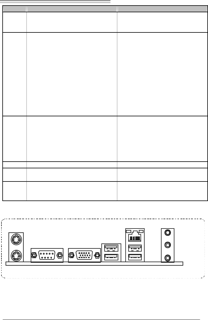
1.4 REAR PANEL CONNECTORS
PS/2
Mouse
PS/ 2
Keyboard
USBX2USBX2
LA N
COM1 VGA
Li ne I n /
Surround
Lin e O ut
Mic In 1/
Bass/ Center
Since t he audio c hip s up ports Hig h Definiti on A udio Specific atio n, t he func tion of eac h a udi o
jack c an be define d b y sof tware. T he in put / out pu t functio n of each au dio jac k listed ab o ve
represe nts t he def ault s etti ng. Ho we ver, wh en c on necti ng e xter nal micr oph on e t o t he au dio
port, pleas e us e t he Lin e I n (blu e) an d Mic In (Pin k) a udio j ac k.
Motherboard Manual
6
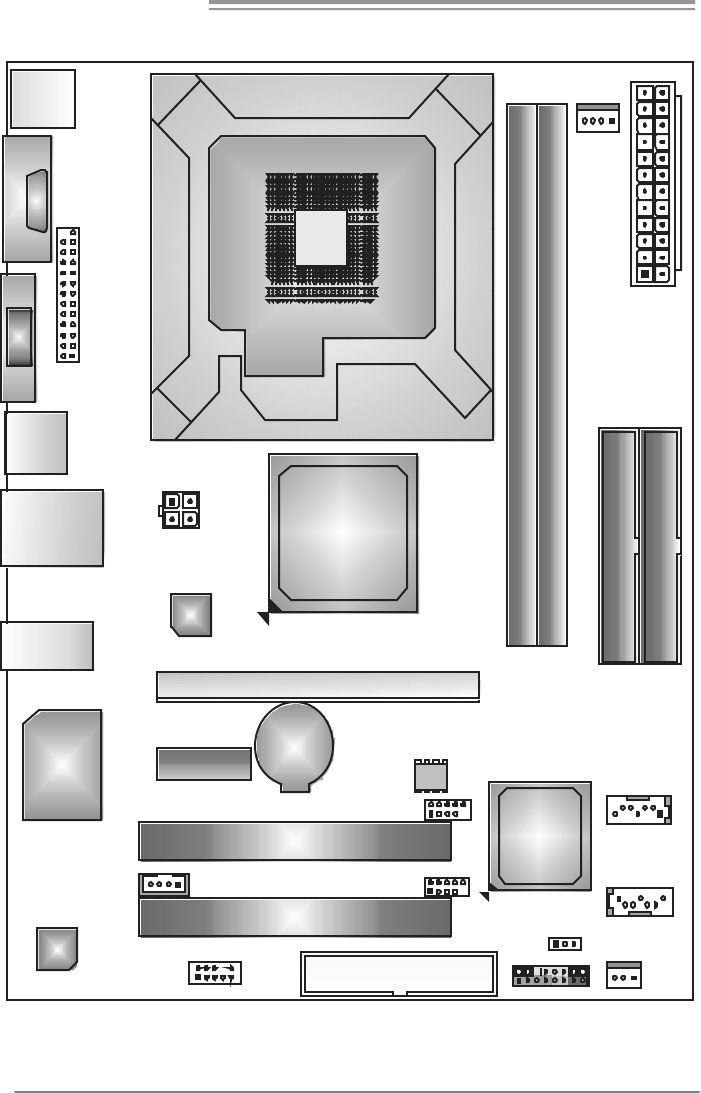
1.5 MOTHERBOARD LAYOUT
Super
I/O
DIMM1
DIMM2
FDD1
PCI-EX1_ 1
PCI -E X16
PCI1
PCI2
J P AN EL 1
JU SB 2
JUSB3
JATXPWR1
JCFAN1
JATXPWR2
JSATA1
JSATA2
Codec
JC DIN1
JSFAN1
BAT1
VIA
VT8237A
LGA775
CPU1
P4M900
or
P4M890
JAUDI OF1
JKB MS1
JUSB1
JUSBLAN1
C
OM1
JCO
M1
JVGA1
IDE1
JCMOS1
LAN
IDE2
BIOS
JAUDIO1
JPRNT1
Note: represents the 1■st pin.
P4M900-M7 SE/P4M890-M7 TE
7
CHAPTER 2: HARDWARE INSTALLATION
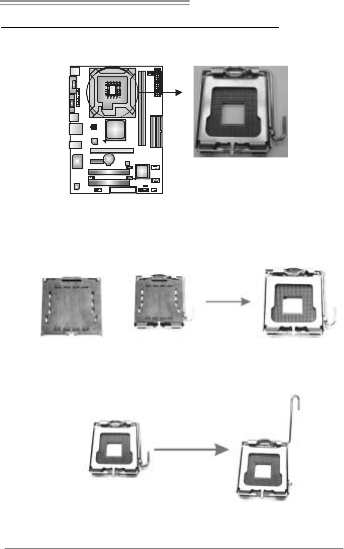
2.1 INSTALLING CENTRAL PROCESSING UNIT (CPU)
Special Notice:
Remove Pin Cap before installation, and make good preservation
for future use. When the CPU is removed, cover the Pin Cap on the
empty socket to ensure pin legs won’t be damaged.
Pin Cap
Step 1: Pull the socket locking lever out from the socket and then raise
the lever up to a 90-degree angle.
Motherboard Manual
8
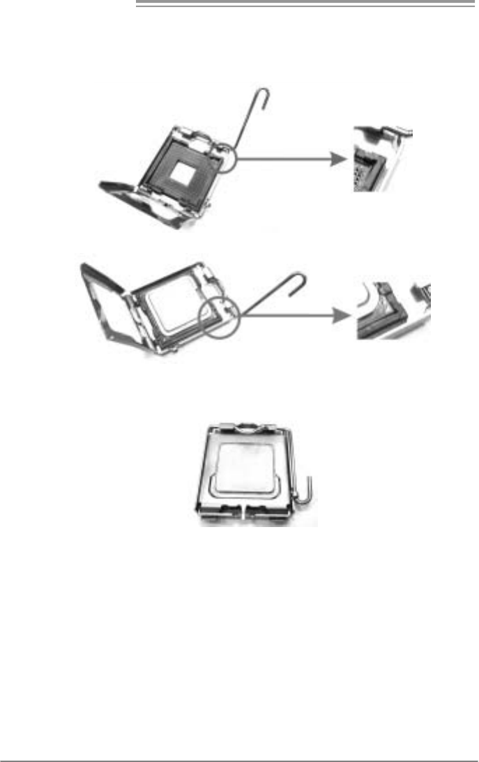
Step 2: Look for the triangular cut edge on socket, and the golden dot on
CPU should point forwards this triangular cut edge. The CPU will
fit only in the correct orientation.
Step 2-1:
Step 2-2:
Step 3: Hold the CPU down firmly, and then lower the lever to locked
position to complete the installation.
Step 4: Put the CPU Fan and heatsink assembly on the CPU and buckle it
on the retention frame. Connect the CPU FAN power cable into
the JCFAN1. This completes the installation.
P4M900-M7 SE/P4M890-M7 TE
9
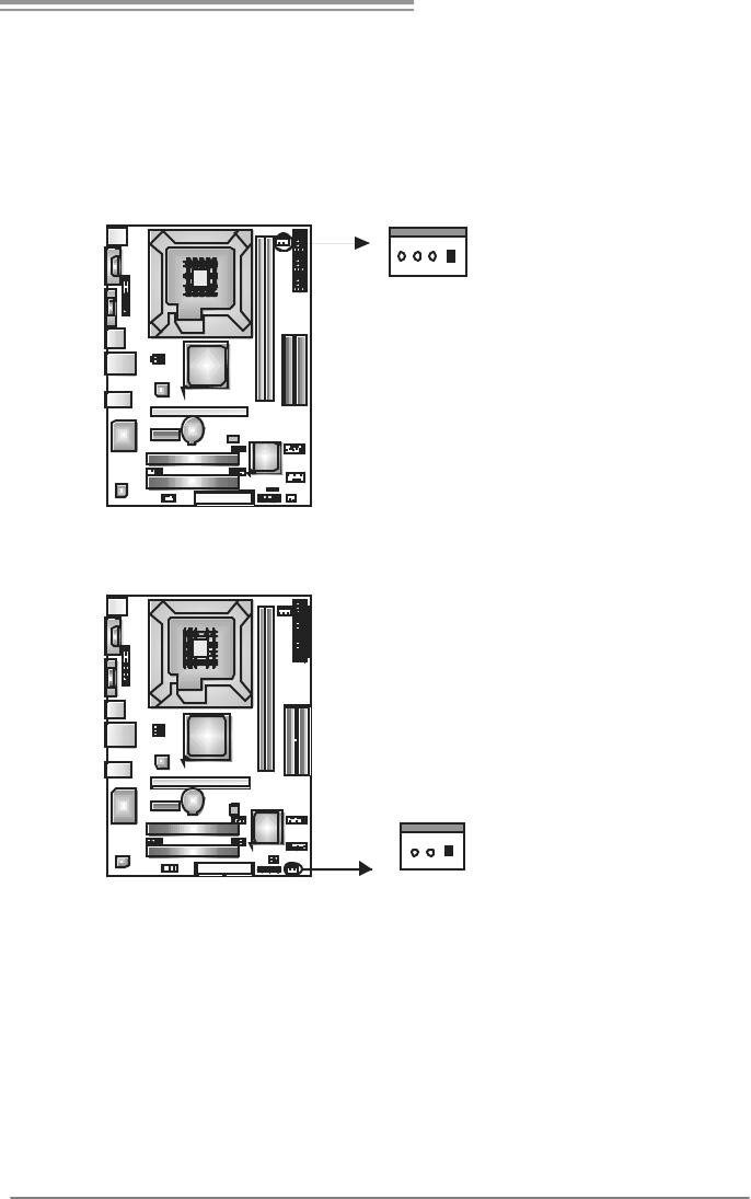
2.2 FAN HEADERS
These fan headers support cooling-fans built in the computer. The fan
cable and connector may be different according to the fan manufacturer.
Connect the fan cable to the connector while matching the black wire to
pin#1.
JCFAN1: CPU Fan Header
Pin
Assignment
1 Ground
2 +12V
3 FAN RPM rate
sense
14
4 Smart Fan
Control
JSFAN1: System Fan Header
Pin
Assignment
1 Ground
2 +12V
13
3 FAN RPM rate
sense
Note:
The JSFAN1 suppor ts 3-pi n he ad c on nect or and the JCFAN1 su pports 4-pin he ad
conn ector . When c on necti ng with wir es on to c on nect ors, pl ease n ote th at t he r ed wi re is
the posi ti ve and s ho uld be c on nect ed to pin# 2, an d the blac k wir e is Gr oun d and s houl d
be c onn ect ed t o GND.
Motherboard Manual
10
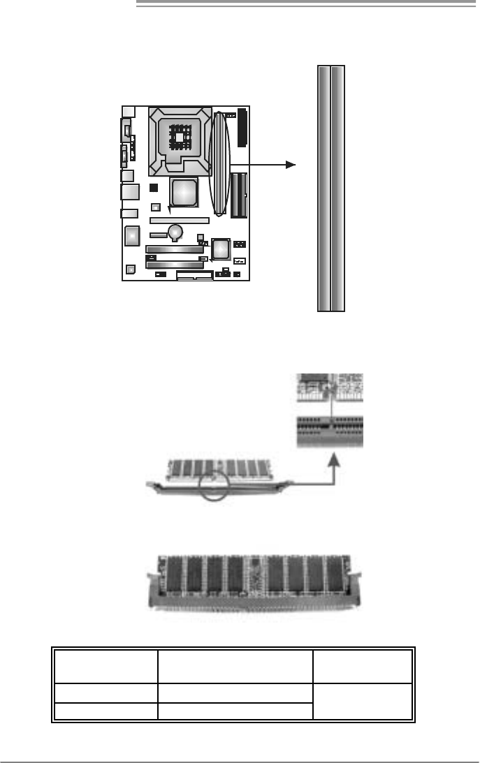
2.3 INSTALLING SYSTEM MEMORY
A. Memory Modules
DIM M1
DIM M2
1. Unlock a DIMM slot by pressing the retaining clips outward. Align a
DIMM on the slot such that the notch on the DIMM matches the
break on the Slot.
2. Insert the DIMM vertically and firmly into the slot until the retaining
chip snap back in place and the DIMM is properly seated.
B. Memory Capacity
DIMM Socket
Location DDR Module To t al Me mo r y
Size
DIMM1 256MB/512MB/1GB/2GB
DIMM2 256MB/512MB/1GB/2GB
Max is 4GB.
P4M900-M7 SE/P4M890-M7 TE
11
2.4 CONNECTORS AND SLOTS
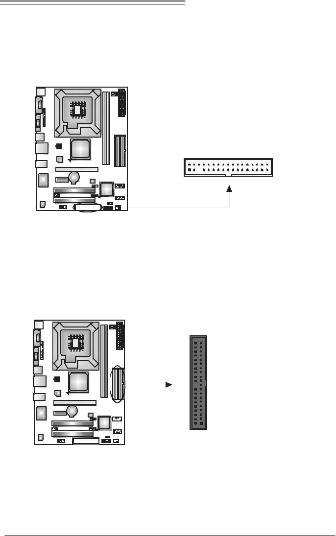
FDD1: Floppy Disk Connector
The motherboard prov ides a standard floppy disk connector that supports 360K,
720K, 1.2M, 1.44M and 2.88M floppy disk ty pes. This connector supports the
prov ided f loppy drive ribbon cable.
34
33
1
2
IDE1/IDE2: Hard Disk Connectors
The motherboard has a 32-bit Enhanced PCI IDE Controller that prov ides PIO
Mode 0~4, Bus Master, and Ultra DMA 33/66/100/133 f unctionality. It has two
HDD connectors: IDE1 (primary ) and IDE2 (secondary ).
The IDE connectors can connect a master and a slav e driv e, so you can
connect up to four hard disk drives. The f irst hard drive should always be
connected to IDE1.
IDE2IDE1
21
3940
Motherboard Manual
12
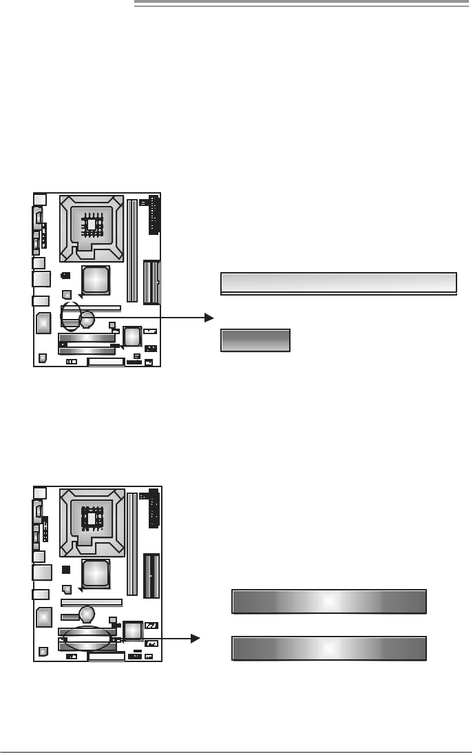
PCI-EX16: PCI-Express x16 Slot
- PCI-Express 1.0a compliant.
- Maximum theoretical realized bandwidth of 4GB/s simultaneously per
direction, f or an aggregate of 8GB/s totally.
PCI-EX1_1: PCI-Express x1 Slot
- PCI-Express 1.0a compliant.
- Data transf er bandwidth up to 250MB/s per direction; 500MB/s in total.
- PCI-Express supports a raw bit-rate of 2.5Gb/s on the data pins.
- 2X bandwidth ov er the traditional PCI architecture.
PCI-EX16
PCI-EX1_1
PCI1/PCI2: Peripheral Component Interconnect Slots
This motherboard is equipped with 2 standard PCI slots. PCI stands f or
Peripheral Component Interconnect, and it is a bus standard for expansion
cards. This PCI slot is designated as 32 bits.
PCI1
PCI2
P4M900-M7 SE/P4M890-M7 TE
13
CHAPTER 3: HEADERS & JUMPERS SETUP
3.1 HOW TO SET UP JUMPERS
The illustration shows how to set up jumpers. When the jumper cap is
placed on pins, the jumper is “close”, if not, that means the jumper is
“open”.
Pin opened Pin closed Pin1-2 closed
3.2 DETAIL SETT INGS
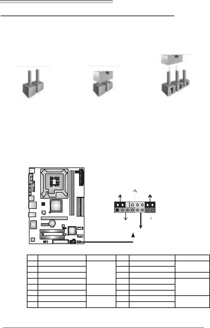
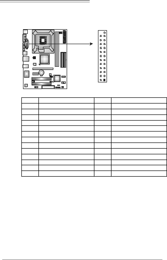
JPANEL1: Front Panel Header
This 16-pin connector includes Power-on, Reset, HDD LED, Power LED, Sleep
button and speaker connection. It allows user to connect the PC case’s f ront
panel switch functions.
18
16
SLP
PWR_LED
On/Off
RS T
HL ED
SPK
++
+
9
-
-
Pin Assignment Functio n Pin Assignment Functio n
1 +5V 9 Sleep control
2 N/A 10 Ground Sleep button
3 N/A 11 N/A N/A
4 Speaker
Speaker
Connector
12 Power LED (+)
5 HDD LED (+) 13 Power LED (+)
6 HDD LED (-)
Hard drive
LED 14 Power LED (-)
Power LED
7 Ground 15 Power button
8 Reset control Reset button 16 Ground Power-on button
Motherboard Manual
14
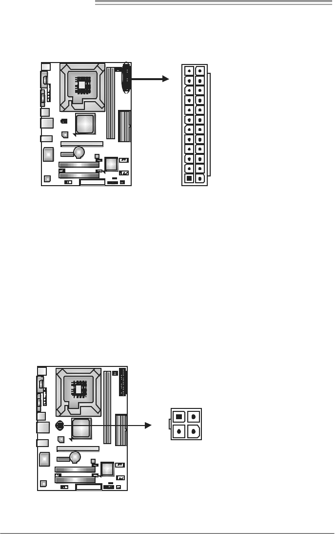
ATX Power Source Connector: JATXPWR1
JATXPWR1 allows user to connect 24-pin power connector on the ATX power
supply.
1
12
13
24
Pin Assignment Pin Assignment
13 +3.3V 1 +3.3V
14 -12V 2 +3.3V
15 Gr ound 3 Groun d
16 PS_ON 4 +5V
17 Gr ound 5 Groun d
18 Gr ound 6 +5V
19 Gr ound 7 Groun d
20 NC 8 PW_OK
21 +5V 9 Standb y Volt ag e+5V
22 +5V 10 +12V
23 +5V 11 +12V
24 Gr ound 12 +3.3V
JATXPW R2: ATX Powe r S ou rce C onne ctor
By connecting this connector, it will provide +12V to CPU power circuit.
Pin
Assignment
1 +12V
2 +12V
3 Ground
1
23
4
4 Ground
P4M900-M7 SE/P4M890-M7 TE
15
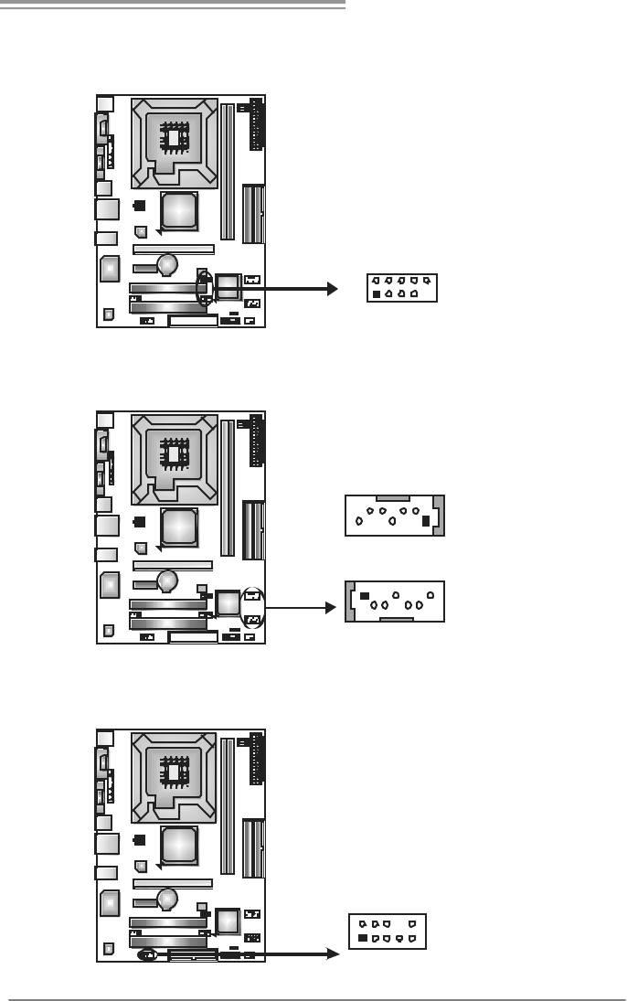
JUSB2/JUSB3: Headers for USB 2.0 Ports at Front Panel
This header allows user to connect additional USB cable on the PC f ront panel,
and also can be connected with internal USB devices, like USB card reader.
Pin
Assignment
1 +5V (fused)
2 +5V (fused)
3 USB-
4 USB-
5 USB+
6 USB+
7 Ground
8 Ground
9 Key
19
210
JUSB2
JUSB3
10 NC
JSATA1/JSATA2: Serial ATA Connectors
The motherboard has a PCI to SATA Controller with 2 channels SATA interf ace,
it satisfies the SATA 1.0 spec and with transfer rate of 1.5Gb/s.
Pin
Assignment
1 Ground
2 TX+
3 TX-
4 Ground
5 RX-
6 RX+
14 7
J SATA1
JSATA2
147
7 Ground
JAUDIOF1: Front Panel Audio Header
This header allows user to connect the front audio output cable with the PC f ront
panel. It will disable the output on back panel audio connectors.
Pin Assignment
1 Mic Left in
2 Ground
3 Mic Right in
4 GPIO
5 Right line in
6 Jack Sense
7 Front Sense
8 Key
9 Left line in
10 Jack Sense
19
210
Motherboard Manual
16
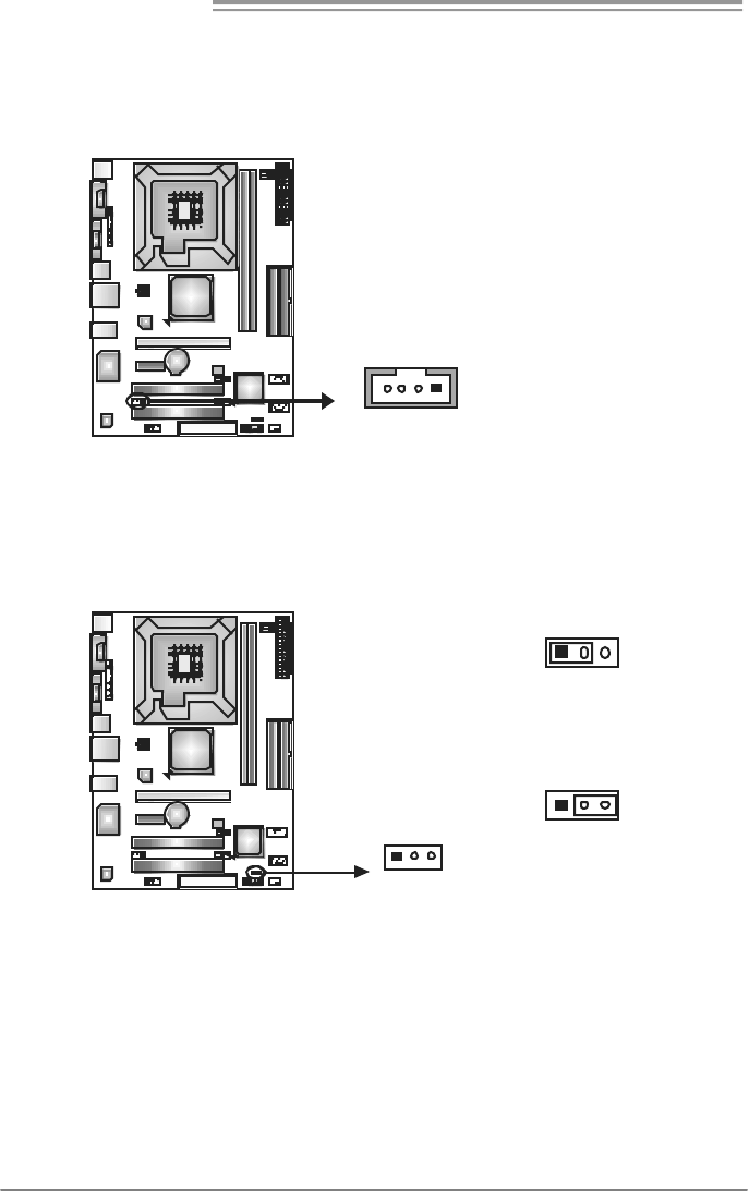
JCDIN1: CD-ROM Audio-in Connector
This connector allows user to connect the audio source f rom the v ariaty dev ices,
like CD-ROM, DVD-ROM, PCI sound card, PCI TV turner card etc.
Pin
Assignment
1 Left Channel Input
2 Ground
3 Ground
14
4 Right Channel Input
JCMOS1: Clear CMOS Header
By placing the jumper on pin2-3, it allows user to restore the BIOS saf e setting
and the CMOS data, please carefully f ollow the procedures to avoid damaging
the motherboard.
13
Pin 1-2 Close:
Normal Operation (default).
13
13
Pin 2-3 Close:
Clear CMOS data.
※ Clear CMOS Procedures:
1. Remov e AC power line.
2. Set the jumper to “Pin 2-3 close”.
3. Wait f or five seconds.
4. Set the jumper to “Pin 1-2 close”.
5. Power on the AC.
6. Reset y our desired password or clear the CMOS data.
P4M900-M7 SE/P4M890-M7 TE
17
JPRNT1: Printer Port Connector
This header allows you to connector printer on the PC.
1
25
2
Pin Assignment Pin Assignment
1 -Strobe 14 Ground
2 -ALF 15 Data 6
3 Data 0 16 Ground
4 -Error 17 Data 7
5 Data 1 18 Ground
6 -Init 19 -ACK
7 Data 2 20 Ground
8 -Scltin 21 Busy
9 Data 3 22 Ground
10 Ground 23 PE
11 Data 4 24 Ground
12 Ground 25 SCLT
13 Data 5 26 Key
Motherboard Manual
18
CHAPTER 4: RAID FUNCTIONS
4.1 OPERATION SYSTEM
z Supports Windows XP Home/Prof essional Edition, and Windows 2000 Prof essional.
4.2 RAID ARRAYS
RAID supports the following types of RAID arrays:
RAID 0: RAID 0 defines a disk striping scheme that improves disk read and write times for
many applications.
RAID 1: RAID 1 defines techniques for mirroring data.
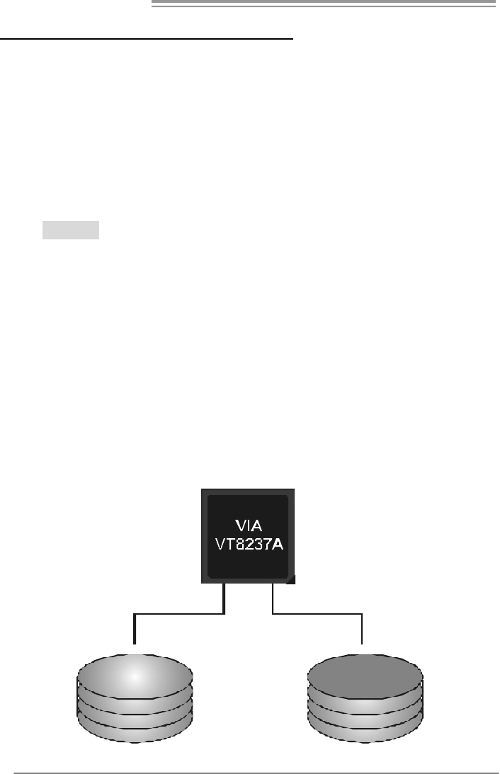
4.3 HOW RAID WORKS
RAID 0:
The controller “ stripes” data across multiple drives in a RAID 0 array system. It breaks
up a large file into smaller blocks and performs disk reads and writes across multiple
drives in parallel. The size of each block is determined by the stripe size parameter,
which you set during the creation of the RAID set based on the system environment. This
technique reduces overall disk access time and offers high bandwidth.
Features and Benefits
Drives: Minimum 1, and maximum is up to 6 or 8. Depending on the
platf orm.
Uses: Intended for non-critical data requiring high data throughput, or any
env ironment that does not require f ault tolerance.
Benefits: prov ides increased data throughput, especially f or large files. No
capacity loss penalty f or parity.
Drawbacks: Does not deliver any fault tolerance. If any drive in the array
f ails, all data is lost.
Fault Tolerance: No.
Blo ck 1
Block 3
Block 5
Block 2
Block 4
Block 6
P4M900-M7 SE/P4M890-M7 TE
19
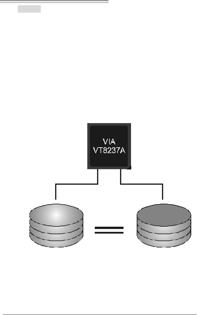
RAID 1:
Every read and write is actually carried out in parallel across 2 disk drives in a RAID 1
array system. The mirrored (backup) copy of the data can reside on the same disk or on a
second redundant drive in the array. RAID 1 provides a hot-standby copy of data if the
active volume or drive is corrupted or becomes unavailable because of a hardware failure.
RAID techniques can be applied for high-availability solutions, or as a form of automatic
backup that eliminates tedious manual backups to more expensive and less reliable
me d i a .
Features and Benefits
Drives: Minimum 2, and maximum is 2.
Uses: RAID 1 is ideal f or small databases or any other application that
requires f ault tolerance and minimal capacity.
Benefits: Prov ides 100% data redundancy. Should one driv e f ail, the
controller switches to the other drive.
Drawbacks: Requires 2 driv es for the storage space of one driv e.
Perf ormance is impaired during driv e rebuilds.
Fault Tolerance: Yes.
Block 1
Block 2
Block 3
Block 1
Block 2
Block 3
Motherboard Manual
20
CHAPTER 5: USEFUL HELP
5.1 DRIVER INSTALLATION NOTE
After you installed your operating system, please insert the Fully Setup
Driver CD into your optical drive and install the driver for better system
performance.
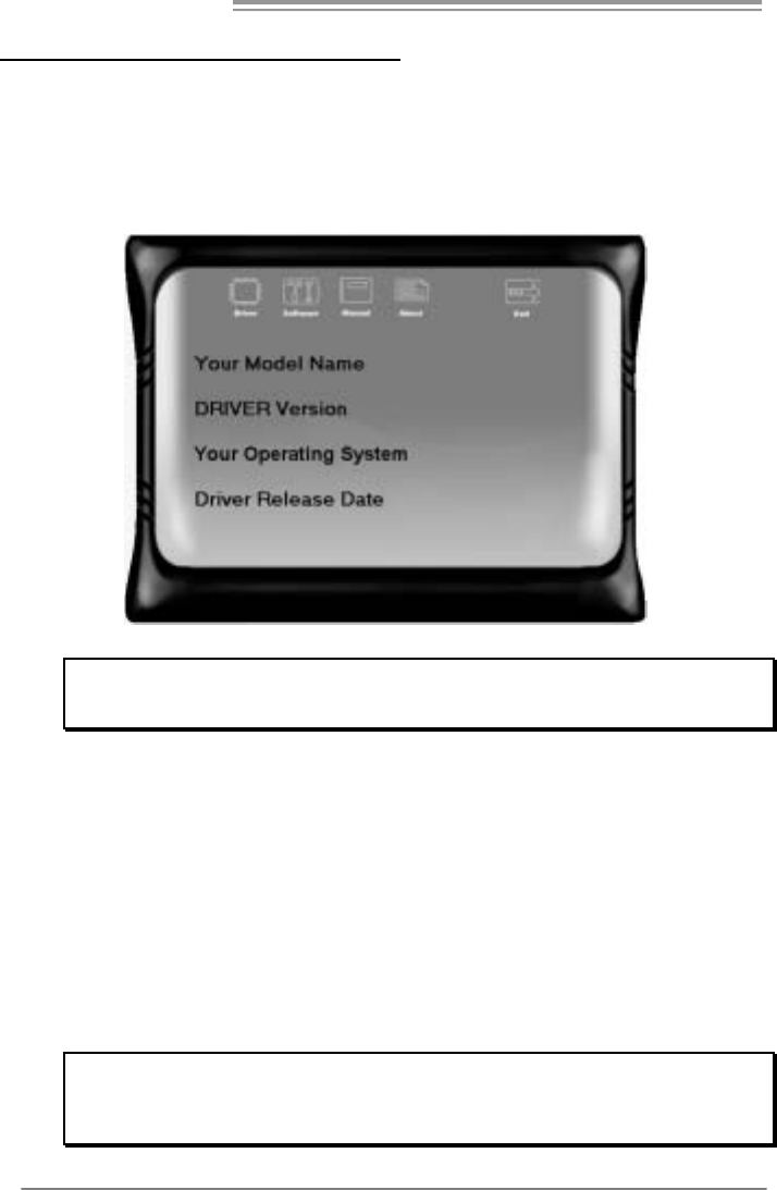
You will see the following window after you insert the CD
The setup guide will auto detect your motherboard and operating system.
Note:
If thi s win dow didn’ t sho w up aft er you ins er t the Dr iver CD, ple ase use file br ows er to
locate an d e xecu te the fil e SETUP.EXE under yo ur o pti cal dri ve .
A. Driver Installation
To install the driver, please click on the Driver icon. The setup guide will
list the compatible driver for your motherboard and operating system.
Click on each device driver to launch the installation program.
B. Software Installation
To install the software, please click on the Software icon. The setup guide
will list the software available for your system, click on each software title
to launch the installation program.
C. Manual
Aside from the paperback manual, we also provide manual in the Driver
CD. Click on the Manual icon to browse for available manual.
Note:
You will need Acrobat Reader to open the manual file. Please download the latest version
of Acrobat Reader software from
http://www.adobe.com/products/acrobat/readstep2.html

P4M900-M7 SE/P4M890-M7 TE
21
5.2 AWARD BIOS BEEP CODE
Beep Sound Meaning
One long beep followed by two short
beeps
Video card not found or v ideo card
memory bad
High-low siren sound CPU overheated
System will shut down automatically
One Short beep when system boot-up No error found during POST
Long beeps every other second No DRAM detected or install
5.3 EXT RA INFORMATION
CPU Overheated
If the system shutdown automatically after power on system for
seconds, that means the CPU protection function has been activated.
When the CPU is over heated, the motherboard will shutdown
automatically to avoid a damage of the CPU, and the system may not
power on again.
In this case, please double check:
1. The CPU cooler surface is placed evenly with the CPU surface.
2. CPU fan is rotated normally.
3. CPU fan speed is fulfilling with the CPU speed.
After confirmed, please follow steps below to relief the CPU protection
function.
1. Remove the power cord from power supply for seconds.
2 . Wa i t f o r se c o nd s.
3. Plug in the power cord and boot up the system.
Or you can:
1. Clear the CMOS data.
(See “Close CMOS Header: JCMOS1” section)
2 . Wa i t f o r se c o nd s.
3. Powe r on the system agai n.

Motherboard Manual
22
5.4 TROUBLESHOOTING
Probable Solution
1. No power to the system at all
Power light don’t illuminate, f an
inside power supply does not turn
on.
2. Indicator light on key board does
not turn on.
1. Make sure power cable is
securely plugged in.
2. Replace cable.
3. Contact technical support.
System inoperativ e. Keyboard lights
are on, power indicator lights are lit,
and hard driv e is spinning.
Using even pressure on both ends of
the DIMM, press down firmly until the
module snaps into place.
System does not boot from hard disk
driv e, can be booted f rom optical driv e.
1. Check cable running from disk to
disk controller board. Make sure
both ends are securely plugged
in; c h ec k t he d riv e ty p e in t h e
standard CMOS setup.
2. Backing up the hard drive is
extremely important. All hard
disks are capable of breaking
down at any time.
System only boots f rom optical driv e.
Hard disk can be read and applications
can be used but booting from hard disk
is impossible.
1. Back up data and applications
files.
2. Ref ormat the hard driv e.
Re-install applications and data
using backup disks.
Screen message says “Invalid
Conf iguration” or “CMOS Failure.”
Rev iew system’s equipment. Make sur
e
correct inf ormation is in setup.
Cannot boot system after installing
second hard driv e.
1. Set master/slave jumpers
correctly.
2. Run SETUP program and select
correct driv e types. Call the drive
manuf acturers f or compatibility
with other drives.

P4M900-M7 SE/P4M890-M7 TE
23
CHAPTER 6: WARPSPEEDER™ III
6.1 INTRODUCTION
[WarpSpeeder™ III], a new powerful control utility, features three
user-friendly functions including Overclock Manager, Overvoltage
Manager, and Hardware Monitor.
With the Overclock Manager, users can easily adjust the frequency they
prefer or they can get the best CPU performance with just one click. The
Overvoltage Manager, on the other hand, helps to power up CPU core
voltage and Memory voltage. The cool Hardware Monitor smartly indicates
the temperatures, voltage and CPU fan speed as well as the chipset
information. Also, in the About panel, you can get detail descriptions about
BIOS model and chipsets. In addition, the frequency status of CPU,
memory, VGA and PCI along with the CPU speed are synchronically
shown on our main panel.
Moreover, to protect users' computer systems if the setting is not
appropriate when testing and results in system fail or hang,
[WarpSpeeder™ III] technology assures the system stability by
automatically rebooting the computer and then restart to a speed that is
either the original system speed or a suitable one.
6.2 SYSTEM REQUIREMENT
OS Support: Windows 98 SE, Windows Me, Windows 2000, Windows XP
DirectX: DirectX 8.1 or above. (The Windows XP operating system
includes DirectX 8.1. If you use Windows XP, you do not need to install
DirectX 8.1.)
Motherboard Manual
24
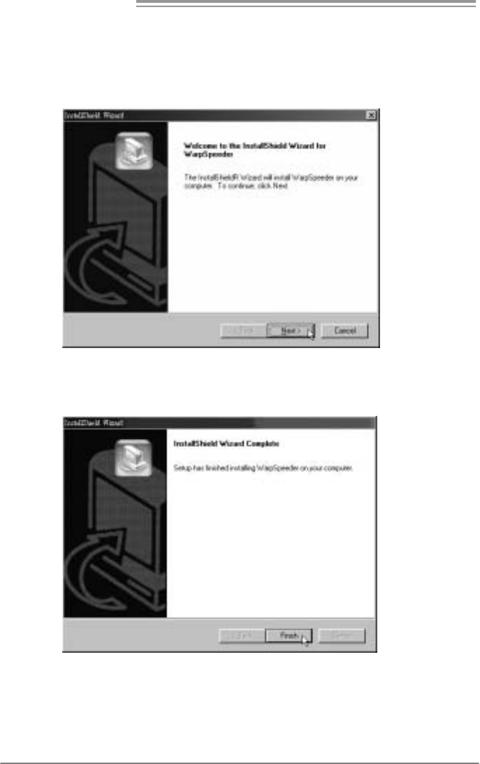
6.3 INSTALLATION
1. Execute the setup execution file, and then the following dialog will pop
up. Please click “Next” button and follow the default procedure to
install.
2. When you see the following dialog in setup procedure, it means setup
is completed. Click “Finish” button.
Usage:
The following figures are only for reference, the screen printed in this
user manual will change according to your motherboard on hand.
P4M900-M7 SE/P4M890-M7 TE
25
6.4 WARPSPEEDER™ III
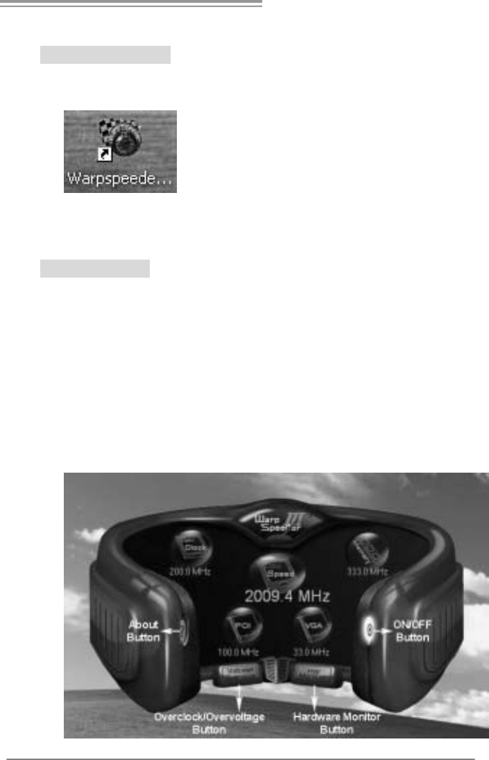
1. Desktop Icon:
After the [WarpSpeeder™ III] has been installed, a [WarpSpeeder™ III]
icon will appear on the desktop, just like the icon shown below.
Now you can launch the [WarpSpeeder™ III] utility simply by
double-clicking the desktop icon.
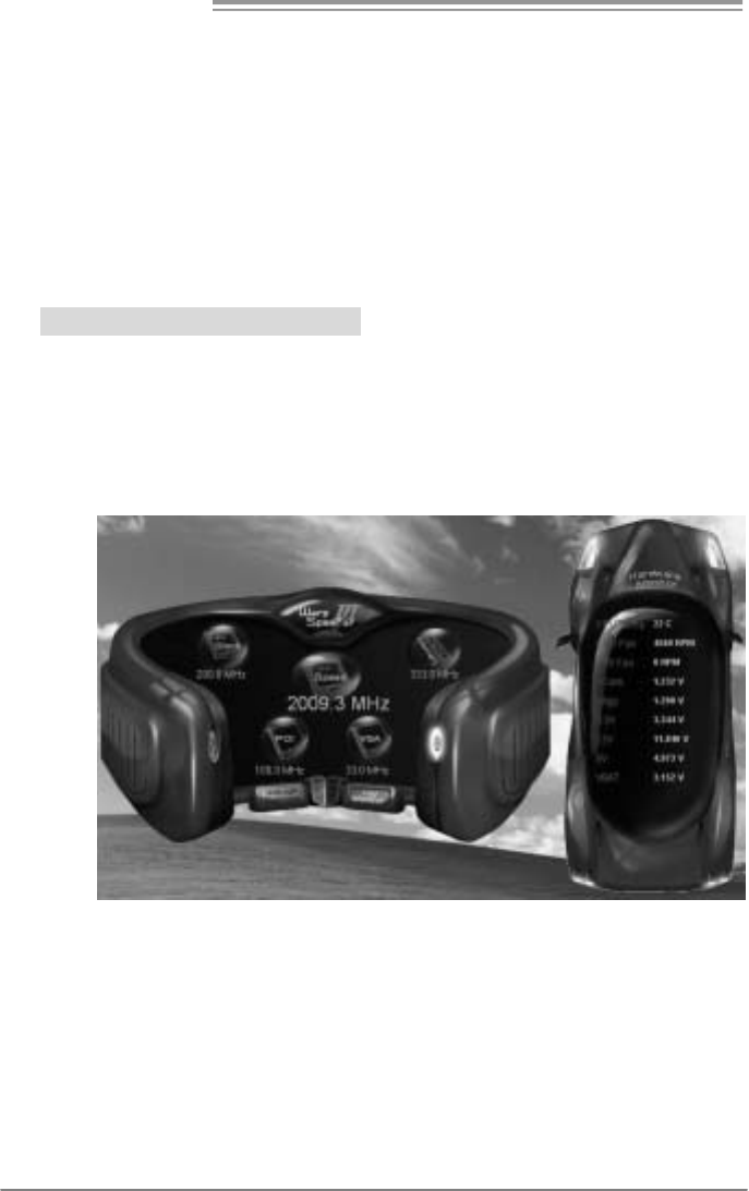
2. Main Panel
If you double-click the desktop icon, [WarpSpeeder™ III] will be
launched. Please refer to the following figure; the utility’s first window
you wi ll see i s Ma in Panel .
Main Panel contains features as follows:
a. Display the CPU Speed, CPU external clock, Memory clock, VGA
clock, and PCI clock information.
b. Contains About, Voltage/Overclock, and Hardware Monitor
Buttons for invoking respective panels. The On/Off button is for
closing the program.
Motherboard Manual
26
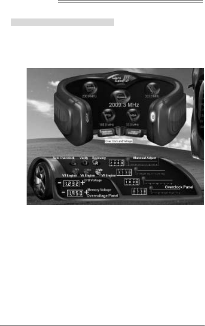
3. Overclock/Overvoltage Panel
Click the Overclock/Overvoltage button in the Main Panel, the button
will be highlighted and the Overclock/Overvoltage Panel will show
up as the following figure. As you can see, the Overclock Panel is
on the right side, and the Overvoltage Panel is on the left side.
P4M900-M7 SE/P4M890-M7 TE
27
Overclock Panel contains these features:
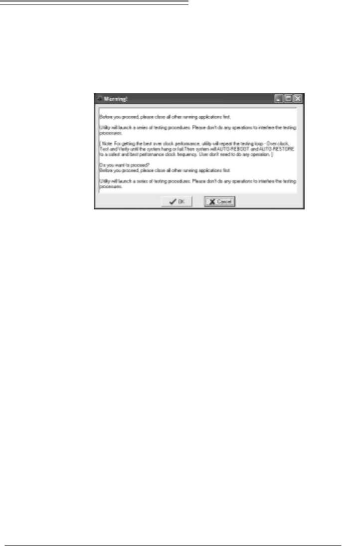
a. “Auto-Overclock”:
User can cli ck this button and [WarpSpeeder™ III] will set the best
and stable performance and frequency automatically. A warning
dialog as below will show up to notify you that the system may
become unstable, click on “OK” to proceed.
Then [WarpSpeeder™ III] utility will execute a series of testing
until system fail. Then system will do fail-safe reboot by using
Watchdog function. After reboot, launch the [WarpSpeeder™ III]
utility again and the utility will load the previously verified best and
stable frequency.
b. “Verify”:
If you use the “Manual Adjust” bar to adjust the CPU frequency,
then you can click this button and [WarpSpeeder™ III] will proceed
a testing for current frequency. If the testing is ok, then the current
frequency will be saved into system registry. If the testing fails,
sy stem will do a fail-safe rebooting. After reboot, the
[WarpSpeeder™ III] utility will restore to the hardware default
setting.
Warning:
Manually overclock is potentially dangerous, especially when the
ov erclocking percentage is over 110 %. We strongly recommend you
v erify ev ery speed you overclock by click the Verify button. Or, you can
just click Auto ov erclock button and let [WarpSpeeder™ III]
automatically gets the best result f or y ou.
c. “V3 Engine”/“V6 Engine”/“V9 Engine”:
Provide user the ability to do real-time overclock adjustment.
d. “Recovery”:
Click this button and the [WarpSpeeder™ III] utility will restore all
values to the hardware default setting.
Motherboard Manual
28
O ve rvoltage Panel contains these features:
a. “CPU Voltage”:
This function allows user to adjust CPU voltage. Click on “+” to
increase or “-“ to decrease the CPU voltage.
b. “Memory Voltage”:
This function allows user to adjust Memory voltage. Click on “+”
to i ncrease or “-“ to decrease the Memory voltage.
4. Hardware Monitor Panel
Cli ck the Hardware Monitor button in Main Panel, the button will be
highlighted and the Hardware Monitor panel will show up as the
following figure.
In this panel, you can get the real-time status information of your
sy stem. T he informati on will be refreshed every 1 second.
P4M900-M7 SE/P4M890-M7 TE
29
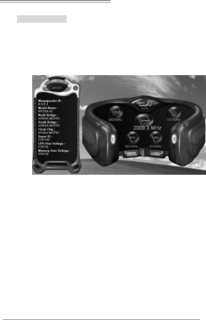
5. About Panel
Click the “about” button in Main Panel, the button will be highlighted
and the About Panel will show up as the following figure.
In this panel, you can get model name and detail information in hints
of all the chipset that are related to overclocking. You can also get
the the version number of [WarpSpeeder™ III] utility.
Note:
Because the overclock, overvoltage, and hardware monitor features
are controlled by several separate chipset, [WarpSpeeder™ III]
divide these features to separate panels. If one chipset is not on
board, the correlative button in Main panel will be disabled, but will
not interfere other panels’ functions. This property can make
[WarpSpeeder™ III] utility more robust.
Motherboard Manual
30
APPENDENCIES: SPEC IN OTHER LANGUAGE
GERMAN
P4M900-M7 SE P4M890-M7 TE
CPU
LGA 77 5
Intel Core2Duo/ Pentium 4 / Pentium D /
Celeron D / Celeron 4xx Prozessoren mit
bis zu 3,8 GHz
Unterstützt Hyper-Threading / Execute
Disable Bit
/
E nha nced I ntel S
p
ee dSte
p
®
/
Intel Architecture-64 / Extended Memory
64 Tech nology
*It is recommended to use
p
rocessors with
95W power c o nsumption.
FSB 533 / 800 / 1 066 MHz 533 / 800 / 1 06 6 MHz
Chipsatz VIA P4M900
VIA VT8237A
VIA P4M890
VIA VT8237A
Grafik
Chrome9 HC 3D / 2 D Graphic s
Max. 256MB gemei nsam be nutzter
Videospeicher
Unichrome Pr o I GP
Max. 64MB gemeinsam benutzter
Videospeicher
Super E/A
ITE 871 2F
Bietet die häufi g verwendete n alte n Super
E/A-Funktio nen.
Low Pin C ount-Schnittstelle
Umgebu ngskontrolle,
Hardware-Überwachung
Lüfterdrehzahl-Controller
"Smart Guar dian"-Funktion v on ITE
ITE 871 2F
Bietet die häufi g verwendete n alte n Super
E/A-Funktio nen.
Low Pin C ount-Schnittstelle
Umgebu ngskontrolle,
Hardware-Überwachung
Lüfterdrehzahl-Controller
"Smart Guar dian"-Funktion v on ITE
Arbeitsspeic
her
DDR2 DIMM-Steckplätze x 2
Unterstützt DDR2 533 / 667
Jeder DIMM unterstützt
256/512MB/1GB/2GB D DR2.
Max. 4GB Arbeitsspeicher
Ein-Kanal D DR2 S peichermod ul
registrierte DIMMs. ECC DIMMs werden
nicht unterstützt.
DDR2 DIMM-Steckplätze x 2
Unterstützt DDR2 533
Jeder DIMM unterstützt
256/512MB/1GB/2GB D DR2.
Max. 4GB Arbeitsspeicher
Ein-Kanal D DR2 S peichermod ul
registrierte DIMMs. ECC DIMMs werden
nicht unterstützt.
IDE
Integrierter IDE-Controller
Ultra DMA 33 / 66 / 100 / 133Bus
Master-Modus
Unterstützt PIO-Modus 0~4,
Integrierter IDE-Controller
Ultra DMA 33 / 66 / 100 / 133Bus
Master-Modus
Unterstützt PIO-Modus 0~4,
SATA
Integrierter Serial ATA-Controller
Datentransferr ate bis z u 1. 5 Gb/s
Konform mit der SATA-Spezifikation
Version 1.0.
Integrierter Serial ATA-Controller
Datentransferr ate bis z u 1. 5 Gb/s
Konform mit der SATA-Spezifikation
Version 1.0.

P4M900-M7 SE/P4M890-M7 TE
31
P4M900-M7 SE P4M890-M7 TE
LAN PHY
Realtek RTL 8201CL PHY/
Atheros AR801 2 PHY (optio nal)
10 / 100 Mb/s A uto-Negotiation
Halb-/ Vollduplex-Funktion
Realtek RTL 8201CL PHY/
Atheros AR801 2 PHY (optio nal)
10 / 100 Mb/s A uto-Negotiation
Halb-/ Vollduplex-Funktion
Audio-Code
c
ALC662
Unterstützt High-Definition Audio
5.1-Kanal-Au dioausg abe
ALC662
Unterstützt High-Definition Audio
5.1-Kanal-Au dioausg abe
PCI-Steckplatz x2 PCI-Steckplatz x2
PCI Express x16 Steckplatz x1 PCI Expr ess x16 Steckplatz x1 Steckplätze
PCI Express x 1-Steckplatz x1 PCI Express x 1-Steckplatz x1
Diskettenlaufwerkanschluss x1 Diskettenlaufwerkanschluss x1
Druckeranschluss Anschluss x1 Druckeranschluss Anschluss x1
IDE-Anschluss x2 IDE-Anschluss x2
SATA-Anschluss x2 SATA-Anschluss x2
Fronttafelanschluss x1 Fronttafelanschluss x1
Front-Audioanschluss x1 Front-Audioanschluss x1
CD-IN-Anschluss x1 CD-IN-Anschluss x1
CPU-Lüfter-Sockel x1 CPU-Lüfter-Sockel x1
System-Lüfter-Sockel x1 System-Lüfter-Sockel x1
"CMOS löschen"-Sockel x1 "CMOS löschen"-Sockel x1
USB-Anschluss x2 USB-Anschluss x2
Stromanschluss (24-polig) x1 Stromanschluss (24-polig) x1
Onboard-An
schluss
Stromanschluss (4-polig) x1 Stromanschluss (4-polig) x1
Rückseiten-
E/A
PS/2-Tastatur x1
PS/2-Maus x1
Serieller Anschluss x1
VGA-Anschluss x1
LAN-Anschluss x1
USB-Anschluss x4
Audioanschluss x3
PS/2-Tastatur x1
PS/2-Maus x1
Serieller Anschluss x1
VGA-Anschluss x1
LAN-Anschluss x1
USB-Anschluss x4
Audioanschluss x3
Platinengr ö
ße. 190 mm (B) X 244 mm (L) 190 mm (B) X 244 mm (L)
Sonderf unkt
ionen Unterstützt RAID 0 / 1 Unterstützt RAID 0 / 1
OS-Unterst
ützung
Windows 2K / XP / VISTA
Biostar behält sich das Recht vor, ohne
Ankündigung die Unterstützung für ein
Betriebssystem hinzuzufü gen oder zu
entfernen.
Windows 2K / XP
Biostar behält sich das Recht vor, ohne
Ankündigung die Unterstützung für ein
Betriebssystem hinzuzufü gen oder zu
entfernen.

Motherboard Manual
32
FRANCE
P4M900-M7 SE P4M890-M7 TE
UC
LGA 77 5
Processeurs Intel Core 2Duo/ P entium 4 /
Pentium D / Celeron D / Celeron 4xx
j
us
q
u'à
3,8 G Hz
Prend en charge les technologies
Hyper -Thre adin g / d'ex écution de bit de
désactivation / Intel SpeedStep®
optimisée/ d'architecture Intel 64 / de
mémoire étendue 64
*It is recommended to use
p
rocessors with
95W power c o nsumption.
Bus frontal
533 / 800 / 1 06 6 MHz 533 / 800 / 1 06 6 MHz
Chipset VIA P4M900
VIA VT8237A
VIA P4M890
VIA VT8237A
Graphi que
s
Chrome9 HC 3D / 2 D Graphic s
Mémoire vidéo partagée maximale de 256
Mo
Unichrome Pr o I GP
Mémoire vidéo partagée maximale de 64
Mo
Super E/S
ITE 871 2F
Fournit la fo nc tionnalité de Super E/S
patrimoniales la plus utilisée.
Interface à faible compte de broc hes
Initiatives de contrôle environnementales,
Moniteur de matériel
Contrôleur de vitess e de ventilateur
Fonction "Gardien i ntelligent" de l'ITE
ITE 871 2F
Fournit la fo nc tionnalité de Super E/S
patrimoniales la plus utilisée.
Interface à faible compte de broc hes
Initiatives de contrôle environnementales,
Moniteur de matériel
Contrôleur de vitess e de ventilateur
Fonction "Gardien i ntelligent" de l'ITE
Mémoire
principale
Fentes DDR 2 DIMM x 2
Prend en charge la DDR 2 533 / 66 7
Chaque DIMM prend e n ch arge des DDR2
de 256 Mo /512 Mo / 1Go / 2 Go
Capacité mémoire maximale de 4 Go
Module de mémoire DDR2 à mode à simple
voie
Les DIMM à registres et DIMM avec code
correcteurs d'erreurs ne sont
p
as
p
rises en
charge
Fentes DDR 2 DIMM x 2
Prend en charge la DDR 2 533
Chaque DIMM prend e n ch arge des DDR2
de 256 Mo /512 Mo / 1Go / 2 Go
Capacité mémoire maximale de 4 Go
Module de mémoire DDR2 à mode à simple
voie
Les DIMM à registres et DIMM avec code
correcteurs d'erreurs ne sont
p
as
p
rises en
charge
IDE
Contrôleur IDE intégr é
Mode
p
ri nci
p
ale de Bus Ultra DMA 33
/
66
/
100 / 133
Prend en charge le mode PIO 0~4,
Contrôleur IDE intégr é
Mode
p
ri nci
p
ale de Bus Ultra DMA 33
/
66
/
100 / 133
Prend en charge le mode PIO 0~4,
SATA
Contrôleur Serial ATA intégré :
Taux de transfert jusqu'à 1.5 Go/s.
Conforme à la spécification SATA Version
1.0
Contrôleur Serial ATA intégré :
Taux de transfert jusqu'à 1.5 Go/s.
Conforme à la spécification SATA Version
1.0

P4M900-M7 SE/P4M890-M7 TE
33
P4M900-M7 SE P4M890-M7 TE
LAN PHY
Realtek RTL 8201CL PHY/
Atheros AR801 2 PHY (en optio n)
10 / 100 Mb/s négociation automatique
Half / Full duplex capability
Realtek RTL 8201CL PHY/
Atheros AR801 2 PHY (en optio n)
10 / 100 Mb/s négociation automatique
Half / Full duplex capability
Codec
audio
ALC662
Prise en c harge de l'audio haute dé finition
Sortie audio à 5.1 voies
ALC662
Prise en c harge de l'audio haute dé finition
Sortie audio à 5.1 voies
Fente PCI x2 Fente PCI x2
Slot PCI Express x16 x1 Slot PCI Express x16 x1 Fentes
Slot PCI Express x 1 x1 Slot PCI Express x 1 x1
Connecteur de disquette x1 Connecteur de disquette x1
Connecteur de P ort d'imprimante x1 Connecteur de P ort d'imprimante x1
Connecteur IDE x2 Connecteur IDE x2
Connecteur SATA x2 Connecteur SATA x2
Connecteur du pa nne au avant x1 Connecteur du pa nne au avant x1
Connecteur Audio d u p ann eau ava nt x1 Connec teur Audio d u pann eau ava nt x1
Connecteur d'entré e CD x1 Connecteur d'entrée CD x1
Embase de ve ntilateur UC x1 Embase de ve ntilateur UC x1
Embase de ventilateur système x1 Embase de ventilateur système x1
Embase d'e ffacement CMO S x1 Embase d'e ffacement CMO S x1
Connecteur USB x2 Connecteur USB x2
Connecteur d'alimentation x1
(24 broches)
Connecteur d'alimentation x1
(24 broches)
Connecteu
r
embarqué
Connecteur d'alimentation x1
(4 br oches)
Connecteur d'alimentation x1
(4 br oches)
E/S d u
pann eau
arrière
Clavier PS/2 x1
Souris PS/2 x1
Port série x1
Port VGA x1
Port LAN x1
Port USB x4
Fiche audio x3
Clavier PS/2 x1
Souris PS/2 x1
Port série x1
Port VGA x1
Port LAN x1
Port USB x4
Fiche audio x3
Dimension
s de la
carte
190 mm (l) X 244 mm (H) 190 mm (l) X 244 mm (H)
Fonctionna
lités
spéciales
Prise en c harge RAID 0 / 1 Prise en c harge RAID 0 / 1
Support
SE
Windows 2K / XP / VISTA
Biostar se réserve le droit d'ajouter ou de
supprimer le supp ort de SE avec o u sa ns
préavis.
Windows 2K / XP
Biostar se réserve le droit d'ajouter ou de
supprimer le supp ort de SE avec o u sa ns
préavis.

Motherboard Manual
34
ITALIAN
P4M900-M7 SE P4M890-M7 TE
CPU
LGA 77 5
Processore Intel Core2Duo/ Pentium 4 /
Pentium D / Celeron D / Celeron 4xx fino a
3.8 G Hz
Supporto di Hyper -T hreadi ng / Execute
Disable Bit
/
E nha nced I ntel S
p
ee dSte
p
®
/
Architettura Intel 64
/
Tecnolo
g
ia Extended
Memory 64
*It is recommended to use
p
rocessors with
95W power c o nsumption.
FSB 533 / 800 / 1 06 6 MHz 533 / 800 / 1 06 6 MHz
Chipset VIA P4M900
VIA VT8237A
VIA P4M890
VIA VT8237A
Grafica
Chrome9 HC 3D / 2 D Graphic s
La memoria video condivisa massima è di
256MB
Unichrome Pr o I GP
La memoria video condivisa massima è di
64MB
Super I/O
ITE 871 2F
Fornisce le funzionalità legacy Super I/O
usate più comunemente.
Interfaccia LPC (Low Pin Count)
Funzioni di controllo dell’ambiente:
Monitoraggio hardware
Controller velocità ventolina
Funzione "Smart G uardi an" di I TE
ITE 871 2F
Fornisce le funzionalità legacy Super I/O
usate più comunemente.
Interfaccia LPC (Low Pin Count)
Funzioni di controllo dell’ambiente:
Monitoraggio hardware
Controller velocità ventolina
Funzione "Smart G uardi an" di I TE
Memoria
principale
Alloggi DIMM DDR 2 x 2
Supporto di DDR2 533 / 667
Ciasc un DIMM su pporta DDR 2 25 6MB /
512MB / 1GB / 2 GB
Capacità massima della memoria 4GB
Modulo di memoria DDR2 a can ale singolo
DIMM registrati e DIMM ECC non sono
supportati
Alloggi DIMM DDR 2 x 2
Supporto di DDR2 533
Ciasc un DIMM su pporta DDR 2 25 6MB /
512MB / 1GB / 2 GB
Capacità massima della memoria 4GB
Modulo di memoria DDR2 a can ale singolo
DIMM registrati e DIMM ECC non sono
supportati
IDE
Controller IDE i ntegrato
Modalità Bus Master Ultra DMA 33 / 66 /
100 / 1 33
Supporto modalità PIO Mode 0- 4
Controller IDE i ntegrato
Modalità Bus Master Ultra DMA 33 / 66 /
100 / 1 33
Supporto modalità PIO Mode 0- 4
SATA
Controller Serial ATA inte grato
Velocità di trasferimento dei dati fi no a 1.5
Gb/s.
Compatibile specifiche SATA Versione 1.0.
Controller Serial ATA inte grato
Velocità di trasferimento dei dati fi no a 1.5
Gb/s.
Compatibile specifiche SATA Versione 1.0.

P4M900-M7 SE/P4M890-M7 TE
35
P4M900-M7 SE P4M890-M7 TE
LAN PHY
Realtek RTL 8201CL PHY/
Atheros AR801 2 PHY (optio nal)
Negoziazione automatic a 10 / 10 0 Mb /s
Capacità Half / Full Duplex
Realtek RTL 8201CL PHY/
Atheros AR801 2 PHY (optio nal)
Negoziazione automatic a 10 / 10 0 Mb /s
Capacità Half / Full Duplex
Codec
audio
ALC662
Supporto audio High-Definition (HD)
Uscita audio 5.1 canali
ALC662
Supporto audio High-Definition (HD)
Uscita audio 5.1 canali
Alloggio PCI x2 Alloggio PCI x2
Alloggio PCI Ex press x1 6 x1 Alloggio PCI Ex press x16 x1
Alloggi
Alloggio PCI Ex press x1 x1 Alloggio PCI Ex press x1 x1
Connettore flo ppy x1 Connettore flo ppy x1
Connettore Porta stampa nte x1 Connettore Porta stampa nte x1
Connettore IDE x2 Connettore IDE x2
Connettore SATA x2 Connettore SATA x2
Connettore pa nnello fro ntale x1 Connettore pa nnello fro ntale x1
Connettore audio frontale x1 Connettore audio frontale x1
Connettore CD-in x1 Connettore CD-in x1
Collettore ventolina CPU x1 Collettore ventolina CPU x1
Collettore ventolina sistema x1 Collettore ventolina sistema x1
Collettore cancellazione CMOS x1 Collettore cancellazione CMOS x1
Connettore USB x2 Connettore USB x2
Connettore alimentazione x1
(24 pin)
Connettore alimentazione x1
(24 pin)
Connettori
su scheda
Connettore alimentazione x1
(4 pi n)
Connettore alimentazione x1
(4 pi n)
I/O
pannello
posteriore
Ta s t i e r a P S / 2 x 1
Mouse PS/2 x1
Porta seriale x1
Porta VGA x1
Porta LAN x1
Porta USB x4
Connettore au dio x3
Ta s t i e r a P S / 2 x 1
Mouse PS/2 x1
Porta seriale x1
Porta VGA x1
Porta LAN x1
Porta USB x4
Connettore au dio x3
Dimension
i scheda 19 0 mm (larghezz a) x 24 4 mm (altezza) 190 mm (larghezza) x 24 4 mm (altezza)
Caratterist
iche
speciali
Supporto RAID 0 / 1 Supporto RAID 0 / 1
Sistemi
operativi
supportati
Windows 2K / XP / VISTA
Biostar si riserva il diritto di aggiungere o
rimuovere il supporto di qualsiasi sistema
operativo se nza preavviso.
Windows 2K / XP
Biostar si riserva il diritto di aggiungere o
rimuovere il supporto di qualsiasi sistema
operativo se nza preavviso.

Motherboard Manual
36
SPANISH
P4M900-M7 SE P4M890-M7 TE
CPU
LGA 77 5
Procesador I ntel Core2Duo / Penti um 4 /
Pentium D / Celeron D / Celeron 4xx hasta
3,8 G Hz
Admite Hyper -T hreadi ng / Bit de
deshabilitación de ejecución / Intel
SpeedStep® Mejora do / Intel
Architecture-64 / Tecnología Extended
Memory 64
*It is recommended to use
p
rocessors with
95W power c o nsumption.
FSB 533 / 800 / 1 06 6 MHz 533 / 800 / 1 06 6 MHz
Conjunto
de chips
VIA P4M900
VIA VT8237A
VIA P4M890
VIA VT8237A
Gráfic os
Chrome9 HC 3D / 2 D Graphic s
Memoria máxima de vídeo compartida de
256MB
Unichrome Pr o I GP
Memoria máxima de vídeo compartida de
64MB
Súper E/S
ITE 871 2F
Le ofrece las funcionalidades heredadas de
uso más común Súper E/S.
Interfaz de cuenta Low Pin
Iniciativas de control de entorno,
Monitor hardware
Controlador de velocida d d e ve ntilador
Función "Guardia inteligente" de ITE
ITE 871 2F
Le ofrece las funcionalidades heredadas de
uso más común Súper E/S.
Interfaz de cuenta Low Pin
Iniciativas de control de entorno,
Monitor hardware
Controlador de velocida d d e ve ntilador
Función "Guardia inteligente" de ITE
Memoria
principal
Ranuras DIMM DDR 2 x 2
Admite DDR2 de 533 / 667
Cada DIMM admite DDR de 25 6MB
/
51 2MB
/1GB / 2GB
Capacidad máxima de memoria de 4GB
Módulo de memoria DDR 2 de canal Sencillo
No admite DIMM registrados o DIMM
compatibles con ECC
Ranuras DIMM DDR 2 x 2
Admite DDR2 de 5 33
Cada DIMM admite DDR de 25 6MB
/
51 2MB
/1GB / 2GB
Capacidad máxima de memoria de 4GB
Módulo de memoria DDR 2 de canal Sencillo
No admite DIMM registrados o DIMM
compatibles con ECC
IDE
Controlador IDE integrado
Modo bus maestro Ultra DMA 33 / 66 / 100
/ 133
Soporte los Mo dos PIO 0~4,
Controlador IDE integrado
Modo bus maestro Ultra DMA 33 / 66 / 100
/ 133
Soporte los Mo dos PIO 0~4,
SATA
Controlador ATA Serie Integrado
Tasas de transferencia de hasta 1.5 Gb/s.
Compatible con la versión SATA 1.0.
Controlador ATA Serie Integrado
Tasas de transferencia de hasta 1.5 Gb/s.
Compatible con la versión SATA 1.0.

P4M900-M7 SE/P4M890-M7 TE
37
P4M900-M7 SE P4M890-M7 TE
Red Local
Realtek RTL 8201CL PHY/
Atheros AR801 2 PHY (opcio nal)
Negociación de 10 / 100 Mb/s
Funciones Half / Full dúplex
Realtek RTL 8201CL PHY/
Atheros AR801 2 PHY (opcio nal)
Negociación de 10 / 100 Mb/s
Funciones Half / Full dúplex
Códecs de
sonido
ALC662
Soporte d e soni do de Alta Defi nición
Salida de sonido de 5.1 canales
ALC662
Soporte d e soni do de Alta Defi nición
Salida de sonido de 5.1 canales
Ranura PCI X2 Ranura PCI X2
Ranura PCI Ex press x1 6 X1 Ranura PCI Ex press x16 X1
Ranuras
Ranura PCI ex press x 1 X1 Ranura PCI ex press x 1 X1
Conector disco flexible X1 Conector disco flexible X1
Conector Puerto de impresora X1 Conector Puerto de impresora X1
Conector IDE X2 Conector IDE X2
Conector SATA X2 Conector SATA X2
Conector de pa nel frontal X1 Conector de pa nel fro ntal X1
Conector de sonido frontal X1 Conector de sonido frontal X1
Conector de entra da de C D X1 Conector de entra da de C D X1
Cabecera de ve ntilador de C PU X1 Cabecera d e ve ntilador de C PU X1
Cabecera de ve ntilador de
sistema X1
Cabecera de ve ntilador de
sistema X1
Cabecera de borrado de CMO S X1 Cabecera d e b orrado de CMOS X1
Conector USB X2 Conector USB X2
Conector de alimentación X1
(24 patillas)
Conector de alimentación X1
(24 patillas)
Conectore
s en placa
Conector de alimentación X1
(4 patillas)
Conector de alimentación X1
(4 patillas)
Panel
trasero de
E/S
Te c l a d o P S / 2 X 1
Ratón PS/2 X1
Puerto serie X1
Puerto VGA X1
Puerto de re d local X1
Puerto USB X4
Conector de sonido X3
Te c l a d o P S / 2 X 1
Ratón PS/2 X1
Puerto serie X1
Puerto VGA X1
Puerto de re d local X1
Puerto USB X4
Conector de sonido X3
Ta m a ño d e
la placa 190mm. (A) X 244 Mm. (H) 190mm. (A) X 244 Mm. (H)
Funciones
especiales Admite RAID 0 / 1 Admite RAID 0 / 1
So
p
orte de
sistema
operativo
Windows 2K / XP / VISTA
Biostar se reserva el derecho de añadir o
retirar el so
p
orte de cual
q
uier SO con o sin
aviso previo.
Windows 2K / XP
Biostar se reserva el derecho de añadir o
retirar el so
p
orte de cual
q
uier SO con o sin
aviso previo.

Motherboard Manual
38
PORTUGUESE
P4M900-M7 SE P4M890-M7 TE
CPU
LGA 77 5
Processador Intel Core2Duo/ Pentium 4 /
Pentium D / Celeron D / Celer on 4xx até 3
,
8
GHz
Suporta as tecnologias Hyper -T hrea ding /
Execute Disable Bit / Enhanced I ntel
SpeedStep® / Intel Arquitecture -64 /
Extende d Memor y 64
*It is recommended to use
p
rocessors with
95W power c o nsumption.
FSB 533 / 800 / 1 06 6 MHz 533 / 800 / 1 06 6 MHz
Chipset VIA P4M900
VIA VT8237A
VIA P4M890
VIA VT8237A
Placa
gráfica
Chrome9 HC 3D / 2 D Graphic s
Memória de vídeo máxima partilhada: 256
MB
Unichrome Pr o I GP
Memória de vídeo máxima partilhada: 64
MB
Especificaç
ão Super
I/O
ITE 871 2F
Proporciona as funcionalidades mais
utilizadas em termos da especificação
Super I/O.
Interfac e LPC (Low Pi n Co unt).
Iniciativas para control o do am biente
Monitorização do hardware
Controlador da velocida de da v entoin ha
Função "Smart Guardia n" da I TE
ITE 871 2F
Proporciona as funcionalidades mais
utilizadas em termos da especificação
Super I/O.
Interfac e LPC (Low Pi n Co unt).
Iniciativas para control o do am biente
Monitorização do hardware
Controlador da velocida de da v entoin ha
Função "Smart Guardia n" da I TE
Memória
principal
Ranhuras DIMM D DR2 x 2
Suporta módulos DDR2 533 / 667
Cada mó dulo DIMM su porta uma memória
DDR2 de 256MB /512 MB / 1 GB / 2GB
Capacidade máxima de memória : 4 GB
Módulo de memória D DR2 de canal simples
Os módulos DIMM registados e os DIMM
ECC não são suportados
Ranhuras DIMM D DR2 x 2
Suporta mó dulos DDR2 5 33
Cada mó dulo DIMM su porta uma memória
DDR2 de 256MB /512 MB / 1 GB / 2GB
Capacidade máxima de memória : 4 GB
Módulo de memória D DR2 de canal simples
Os módulos DIMM registados e os DIMM
ECC não são suportados
IDE
Controlador IDE integrado
Modo Bus mas ter Ultra DMA 33 / 6 6 / 10 0
/
133
Suporta o mod o PIO 0~4,
Controlador IDE integrado
Modo Bus mas ter Ultra DMA 33 / 6 6 / 10 0
/
133
Suporta o mod o PIO 0~4,
SATA
Controlador Serial ATA integrado
Velocidades de transmissão de dados até
1.5 G b/s.
Compatibilidade com a especificação SATA
versão 1. 0.
Controlador Serial ATA integrado
Velocidades de transmissão de dados até
1.5 G b/s.
Compatibilidade com a especificação SATA
versão 1. 0.

P4M900-M7 SE/P4M890-M7 TE
39
P4M900-M7 SE P4M890-M7 TE
LAN PHY
Realtek RTL 8201CL PHY/
Atheros AR801 2 PHY (opcio nal)
Auto ne gociaç ão de 10 / 100 MB/s
Capacidade semi/full- duplex
Realtek RTL 8201CL PHY/
Atheros AR801 2 PHY (opcio nal)
Auto ne gociaç ão de 10 / 100 MB/s
Capacidade semi/full- duplex
Codec de
som
ALC662
Suporta a especificação High-Definition
Audio
Saída de á udio de 5.1 ca nais
ALC662
Suporta a especificação High-Definition
Audio
Saída de á udio de 5.1 ca nais
Ranhura PCI x2 Ranhura PCI x2
Ranhura PCI Express x 16 x1 Ranhura PCI Express x 16 x1 Ranhuras
Ranhura PCI Express x 1 x1 Ranhura PCI Express x 1 x1
Conector da u nida de de disquetes x 1 Conector da u nida de de disquetes x 1
Conector da para impressora x1 Conector da para impressora x1
Conector IDE x2 Conector IDE x2
Conector SATA x2 Conector SATA x2
Conector do pai nel fro ntal x1 Conector do pai nel frontal x1
Conector de áu dio fro ntal x1 Conector de áudio frontal x1
Conector para e ntrada de C Ds x1 Conector para e ntrada de C Ds x1
Conector da ve ntoinh a da CPU x1 Conector da ve ntoinh a d a CPU x1
Conector da ve ntoinh a d o
sistema x1
Conector da ve ntoinh a d o
sistema x1
Conector para limpeza do CMOS x1 Conector para limpeza do CMOS x1
Conector USB x2 Conector USB x2
Conector de alimentação x1
(24 pinos)
Conector de alimentação x1
(24 pinos)
Conectore
s na placa
Conector de alimentação x1
(4 pi nos)
Conector de alimentação x1
(4 pi nos)
Entradas/
Saídas no
painel
traseiro
Te c l a d o P S / 2 x 1
Rato PS/2 x1
Porta série x1
Porta VGA x1
Porta LAN x1
Porta USB x4
Tomada de áudio x3
Te c l a d o P S / 2 x 1
Rato PS/2 x1
Porta série x1
Porta VGA x1
Porta LAN x1
Porta USB x4
Tomada de áudio x3
Ta m a n h o
da pl aca 19 0 mm (L) X 244 mm (A) 19 0 mm (L) X 24 4 mm (A)
Característ
icas
especiais
Suporta as funções RAID 0 / 1 Suporta as funções RAID 0 / 1
Sistemas
operativos
suportado
s
Windows 2K / XP / VISTA
A Biostar reserva-se o direito de adicionar
ou remover suporte para qualquer sistema
operativo com ou sem aviso prévio.
Windows 2K / XP
A Biostar reserva-se o direito de adicionar
ou remover suporte para qualquer sistema
operativo com ou sem aviso prévio.

Motherboard Manual
40
POLISH
P4M900-M7 SE P4M890-M7 TE
Procesor
LGA 77 5
Procesor Intel Cor e2Duo/ Penti um 4 /
Pentium D / Celeron D / Celeron 4xx do 3
,
8
GHz
Obsługa Hyper-Threadin
g
/
Exec ute Disable
Bit / Enhanced Intel SpeedStep® / Intel
Architecture-64 / Extended Memory 64
Technol ogy
*It is recommended to use
p
rocessors with
95W power c o nsumption.
LGA 77 5
Procesor Intel Cor e2Duo/ Penti um 4 /
Pentium D / Celeron D / Celeron 4xx do 3
,
8
GHz
Obsługa Hyper-Threadin
g
/
Exec ute Disable
Bit / Enhanced Intel SpeedStep® / Intel
Architecture-64 / Extended Memory 64
Technol ogy
*It is recommended to use
p
rocessors with
95W power c o nsumption.
FSB 533 / 800 / 1 06 6 MHz 533 / 800 / 1 06 6 MHz
Chipset VIA P4M900
VIA VT8237A
VIA P4M890
VIA VT8237A
Grafika
Chrome9 HC 3D / 2 D Graphic s
Maks. wielkość współdzielonej pamięci
video wy nosi 2 56MB
Unichrome Pr o I GP
Maks. wielkość współdzielonej pamięci
video wynosi 64MB
Pamięć
główna
Gniazda DDR 2 DIMM x 2
Obsługa D DR2 53 3 / 6 67
Każde gniazd o DIMM obsługuje moduły
256MB /5 12MB / 1 GB / 2GB DDR2
Maks. wielkość pamięci 4GB
Moduł pamięci DDR2 z trybem
poje dynczego kanału
Brak obsługi Registered DIMM or az ECC
DIMM
Gniazda DDR 2 DIMM x 2
Obsługa D DR2 53 3
Każde gniazd o DIMM obsługuje moduły
256MB /5 12MB / 1 GB / 2GB DDR2
Maks. wielkość pamięci 4GB
Moduł pamięci DDR2 z trybem
poje dynczego kanału
Brak obsługi Registered DIMM or az ECC
DIMM
Super I/O
ITE 871 2F
Zapewnia najbardziej powszechne f unkc je
Super I/O.
Interfejs Low Pin Count
Funkc je kontroli warunków prac y,
Monitor H/W
Kontroler prędkości wentylatora
Funkcja ITE "Smart Guar dian"
ITE 871 2F
Zapewnia najbardziej powszechne f unkc je
Super I/O.
Interfejs Low Pin Count
Funkc je kontroli warunków prac y,
Monitor H/W
Kontroler prędkości wentylatora
Funkcja ITE "Smart Guar dian"
IDE
Zintegrowany kontroler ID E
Ultra DMA 33 / 66 / 100 / 133 Tryb Bus
Master
obsługa PIO tryb 0~4,
Zintegrowany kontroler ID E
Ultra DMA 33 / 66 / 100 / 133 Tryb Bus
Master
obsługa PIO tryb 0~4,
SATA
Zintegrowany kontroler Serial ATA
Transfer danych do 1.5 Gb/s.
Zgodność ze specyfikacją SATA w wersji
1.0.
Zintegrowany kontroler Serial ATA
Transfer danych do 1.5 Gb/s.
Zgodność ze specyfikacją SATA w wersji
1.0.

P4M900-M7 SE/P4M890-M7 TE
41
P4M900-M7 SE P4M890-M7 TE
LAN PHY
Realtek RTL 8201CL PHY/
Atheros AR801 2 PHY (opc ja)
10 / 100 Mb/s z automatyczną neg ocjacją
szybkości
Działanie w trybie połowicznego / pełnego
dupleksu
Realtek RTL 8201CL PHY/
Atheros AR801 2 PHY (opc ja)
10 / 100 Mb/s z automatyczną neg ocjacją
szybkości
Działanie w trybie połowicznego / pełnego
dupleksu
Kodek
dźwiękowy
ALC662
Obsługa High-Definition Audio
5.1 ka nałowe wy jście audio
ALC662
Obsługa High-Definition Audio
5.1 ka nałowe wy jście audio
Gniazdo PCI x2 Gniazdo PCI x2
Gniazdo PCI Express x16 x1 Gniazdo PCI Express x16 x1 Gniazda
Gniazdo PCI Express x 1 x1 Gniazdo PCI Express x 1 x1
Złącze napędu dyskietek x1 Złącze napędu dyskietek x1
Złącze Port drukarki x1 Złącze Port drukarki x1
Złącze IDE x2 Złącze IDE x2
Złącze SATA x2 Złącze SATA x2
Złącze panela przed niego x1 Złącze panela przedniego x1
Przednie złącze a udio x1 Przednie złącze audio x1
Złącze wejścia CD x1 Złącze wejścia CD x1
Złącze główkowe wentylatora procesora x1 Złącze główkowe wentylatora procesora x1
Złącze główkowe wentylatora
systemowego x1
Złącze główkowe wentylatora
systemowego x1
Złącze główkowe kasowani a
CMOS x1
Złącze główkowe kasowani a
CMOS x1
Złącze USB x2 Złącze USB x2
Złącze zasilania (24 pi nowe) x1 Złącze zasilania (24 pi nowe) x1
Złącza
wbudowan
e
Złącze zasilania (4 pinowe) x1 Złącze zasilania (4 pinowe) x1
Back Panel
I/O
Klawiatura PS/2 x1
Mysz PS/2 x1
Port szeregowy x1
Port VGA x1
Port LAN x1
Port USB x4
Gniazdo audio x3
Klawiatura PS/2 x1
Mysz PS/2 x1
Port szeregowy x1
Port VGA x1
Port LAN x1
Port USB x4
Gniazdo audio x3
Wymiary
płyty 190 mm (S) X 244 mm (W) 190 mm (S) X 244 mm (W)
Funkc je
specjalne Obsługa RAID 0 / 1 O bsługa RAID 0 / 1
Obsluga
systemu
operacyjn
ego
Windows 2K / XP / VISTA
Biostar zastrzega sobie prawo do dawania
lub odwoływania obsługi dowolnego
systemu operacyjnego bez powiadomienia.
Windows 2K / XP
Biostar zastrzega sobie prawo do dawania
lub odwoływania obsługi dowolnego
systemu operacyjnego bez powiadomienia.

Motherboard Manual
42
RUSSIAN
P4M900-M7 SE P4M890-M7 TE
CPU
(централь
ны й
проц ес сор
)
LGA 77 5
Процессор Intel Core 2Du o/ Pe ntium 4 /
Pentium D / Celeron D / Celeron 4xx до 3. 8
ГГц
Подде рж ка техн оло гий Hyper-Threadin
g
/
Execute Disable Bit / Enhanced I ntel
SpeedStep® / Intel Architecture-64 /
Extende d Memor y 64 Tech nology
*It is recommended to use
p
rocessors with
95W power c o nsumption.
FSB 533 / 800 / 1 06 6 МГц 533 / 800 / 1 066 МГц
Набор
микросхе
м
VIA P4M900
VIA VT8237A
VIA P4M890
VIA VT8237A
Графика
Chrome9 HC 3D / 2 D Graphic s
Максимальн ая совмес тно исп ользуем ая
видео память составляет 256 МБ
Unichrome Pr o I GP
Максимальн ая совмес тно исп ользуем ая
видео память составляет 64 МБ
Основная
память
Слоты DDR2 DIMM x 2
Подде рж ка DDR2 533 / 667
Каждый модуль DIMM по ддерж ивае т
256MB / 51 2МБ / 1ГБ / 2ГБ DDR2
Максимальн ая ёмк ость памя ти 4 ГБ
Модуль памя ти с од нока наль ны м
реж имом DDR2
Не подде рж ивае т з а рег истр иров ан ны е
модули DIMM and ECC DIMM
Слоты DDR2 DIMM x 2
Подде рж ка DDR2 5 33
Каждый модуль DIMM по ддерж ивае т
256MB / 51 2МБ / 1ГБ / 2ГБ DDR2
Максимальн ая ёмк ость памя ти 4 ГБ
Модуль памя ти с од нока наль ны м
реж имом DDR2
Не подде рж ивае т з а рег истр иров ан ны е
модули DIMM and ECC DIMM
Super I/O
ITE 871 2F
Обеспечива ет на ибо лее ис по льз уем ы е
действ ующие функциональные
возможности Super I/O.
Инте рфейс с низким количеством
выводов
Иниц иа ти вы по охране ок ружающей
среды,
А ппара тны й монитор
Регуля тор скорости
Функция ITE "Smart Guardian"
(Интелле ктуа льна я защита)
ITE 871 2F
Обеспечива ет на ибо лее ис по льз уем ы е
действ ующие функциональные
возможности Super I/O.
Инте рфейс с низким количеством
выводов
Иниц иа ти вы по охране ок ружающей
среды,
А ппара тны й монитор
Регуля тор скорости
Функция ITE "Smart Guardian"
(Интелле ктуа льна я защита)
IDE
Встроен ное устройств о управления
встрое нны м и ин терф е йс ами устройств
Режим " хозяина" шины Ultra DMA 33
/
66
/
100 / 133
Подде рж ка режима PIO 0~4,
Встроен ное устройств о управления
встрое нны м и ин терф е йс ами устройств
Режим " хозяина" шины Ultra DMA 33
/
66
/
100 / 133
Подде рж ка режима PIO 0~4,
SATA
Встроен ное посл едов ате льное
устройс тво управле ния ATA
скорость пер едач и данных до 1. 5
гига бит/с.
Соотве тств ие специ
ф
икац и и SATA ве
р
сия
1.0.
Встроен ное посл едов ате льное
устройс тво управле ния ATA
скорость пер едач и данных до 1. 5
гига бит/с.
Соотве тств ие специ
ф
икац и и SATA ве
р
сия
1.0.

P4M900-M7 SE/P4M890-M7 TE
43
P4M900-M7 SE P4M890-M7 TE
Локаль на
я сеть
Realtek RTL 8201CL PHY/
Atheros AR801 2 PHY (до пол ни тель но)
Автоматическое согласование 10 / 100
Мб/с
Частич ная / пол ная дуплексна я
способнос ть
Realtek RTL 8201CL PHY/
Atheros AR801 2 PHY (до пол ни тель но)
Автоматическое согласование 10 / 100
Мб/с
Частич ная / пол ная дуплексна я
способнос ть
Звуково й
кодек
ALC662
Звукова я поддержка High-Definition
5.1кана льны й звуков ой выход
ALC662
Звукова я поддержка High-Definition
5.1кана льны й звуков ой выход
Слот PCI x2 Слот PCI x2
Слот PCI Express x16 x1 Слот PCI Express x16 x1
Слоты
Слот PCI Express x 1 x1 Слот PCI Ex press x 1 x1
Разъём НГМД x1 Разъём НГМД x1
Разъём Порт под ключе ния принтера x1 Разъём Пор т под ключе ния принтера x1
Разъём IDE x2 Разъём IDE x2
Разъём SATA x2 Разъём SATA x2
Разъём на лицево й пане ли x1 Разъём на лицево й пане ли x1
Входной звук овой раз ъём x1 Входной звук овой раз ъём x1
Разъём вв ода дл я CD x1 Разъём вв ода дл я CD x1
Контактирующее п рис пос о бле ние
вент иля тор а ц ент раль ного процессора x1
Контактирующее п рис пос о бле ние
вент иля тор а ц ент раль ного пр оц есс ора x1
Контактирующее п рис пос о бле ние
вент иля тор а системы x1
Контактирующее п рис пос о бле ние
вент иля тор а системы x1
Открытое кон так тирующее
прис пособл ени е CMOS x1
Открытое кон так тирующее
прис пособл ени е CMOS x1
USB-разъём x2 USB-разъём x2
Разъем пит ан ия (24 вывод) x1 Разъем пит ан ия (24 вывод) x1
Встроенн
ый разъём
Разъем пит ан ия (4 вывод) x1 Разъем пит ан ия (4 вывод) x1
Задн яя
пане ль
средств
ввода-выв
ода
Клавиатура PS/ 2 x1
Мышь PS/2 x1
Последо вате льный по рт x1
Порт VGA x1
Порт LAN x1
USB-порт x4
Гнездо для по дключ ени я
наушников x3
Клавиатура PS/ 2 x1
Мышь PS/2 x1
Последо вате льный по рт x1
Порт VGA x1
Порт LAN x1
USB-порт x4
Гнездо для по дключ ени я
наушников x3
Размер
пане ли 190 мм (Ш) X 244 мм (В) 19 0 мм (Ш) X 244 мм (В)
Специаль
ны е
техн ическ
ие
харак тер и
стики
Подде рж ка RAID 0 / 1 Подде рж ка RAID 0 / 1
Подде рж к
а OS
Windows 2K / XP / VISTA
Biostar сохраняет за собой прав о
добав лять или уда лять средс тва
обес пече ни я для OS с ил и без
пред вар ите льно го уведомления.
Windows 2K / XP
Biostar сохраняет за собой прав о
добав лять или уда лять средс тва
обес пече ни я для OS с ил и без
пред вар ите льно го уведомления.

Motherboard Manual
44
ARABIC
P4M900-M7 SE P4M890-M7 TE
ةﺪﺣو ﺔﺠﻟﺎﻌﻤﻟا
ﺔ ﻳﺰآﺮﻤﻟا
LGA 775
تﺎﺠﻟﺎﻌﻡIntel Core2Duo
/
Pe ntium 4
/
Pentium
D / C eleron D / Celer on 4xx ﺑ ددﺮﺘ ﻳ ﻰﻟإ ﻞﺼ8.3
ﺰﺕﺮه ﺎﺠﻴﺝ
تﺎﻴﻨﻘﺕ ﻢﻋﺪﺕHyper -Thre adin
g
/
Exec ute Disabl e
Bit
/
En hance d I ntel S
p
ee dSte
p
®
/
Extende d Memor y 64 Tech nology
*It is recommended to use
p
rocessors with
95W power c o nsumption.
LGA 77 5
تﺎﺠﻟﺎﻌﻡIntel Core2Duo
/
Pe ntium 4
/
Pentium
D / C eleron D / Celer on 4xx ﺑ ددﺮﺘ ﻳ ﻰﻟإ ﻞﺼ8.3
ﺰﺕﺮه ﺎﺠﻴﺝ
تﺎﻴﻨﻘﺕ ﻢﻋﺪﺕHyper -Thre adin
g
/
Exec ute Disabl e
Bit
/
En hance d I ntel S
p
ee dSte
p
®
/
Extende d Memor y 64 Tech nology
*It is recommended to use processors with
95W power c o nsumption.
ﻟاﻞﻗﺎﻨ ﻲﻡﺎﻡﻷا
ﻲﺒﻥﺎﺠﻟا
ددﺮﺕ 5 33 / 800 / 10 66 ﺰﺕﺮه ﺎﺠﻴﻡ
ددﺮﺕ 5 33 / 800 / 10 66 ﺰﺕﺮه ﺎﺠﻴﻡ
ﺔﻋﻮﻤﺠﻡ ﺢﺋاﺮﺸﻟا
VIA P4M900
VIA VT8237A
VIA P4M890
VIA VT8237A
تﺎ ﻡ ﻮ ﺳ ﺮﻟ ا ﺔﻗﺎﻄﺑ
Chrome9 HC 3D / 2 D Graphic s
ﺔآﺮﺘﺸﻤﻟا ﻮﻳﺪﻴﻔﻟا ةﺮآاﺬﻟ ﺔﻌﺳ ﻰﺼﻗأ256 ﺖﻳ ﺎ ﺑ ﺎﺠﻴﻡ
Unichrome Pr o I GP
ﺔآﺮﺘﺸﻤﻟا ﻮﻳﺪﻴﻔﻟا ةﺮآاﺬﻟ ﺔﻌﺳ ﻰﺼﻗأ64 ﺖﻳ ﺎﺑ ﺎﺠﻴﻡ
ةﺮآاﺬﻟا ﺔﻴﺴﻴﺋﺮﻟا
ﺔﺤﺘ ﻓDDR2 DIMM دﺪﻋ2
ﻢﻋﺪﺕ ةﺮآاﺬﻟا ﻦﻡ عﻮﻥ DDR2 تﺎﻌﺳ 533 / 66 7 ﺎﺠﻴﻡ ﺖﻳ ﺎﺑ
ﻢﻋﺪﺕ ﻞآ ﺔﺤﺘﻓ DIMM ﻢﻋﺪﺕ ةﺮآاذ ﻦﻡ عﻮﻥ DDR2 ﺔﻌﺳ
256 ﺎﺠﻴﻡ ﺖﻳ ﺎ ﺑ /512 ﺎﺠﻴﻡ ﺖﻳﺎﺑ و1 ﺎﺠﻴﺝ ﺖﻳﺎﺑ / 2 ﺎﺠﻴﺝ
ﺖﻳﺎﺑ
ﺔﻌﺳ ةﺮآاذ ﻗىﻮﺼ 4 ﺎﺠﻴﺝ ﺖﻳ ﺎ ﺑ
ةﺪﺣو ةﺮآ اذ DDR2 ﺔﻳدﺎﺣأ ةﺎﻨﻘﻟا
ةﺮآاﺬﻟا ﻖﺋﺎﻗر ﻢﻋﺪﺕ ﻻDIMM ﻊﻡ ﻖﻓاﻮﺘﺕ ﻻ ﻲﺘﻟا ﻚﻠﺕو ECC
ﺔﺤﺘ ﻓDDR2 DIMM دﺪﻋ2
ﻢﻋﺪﺕ ةﺮآاﺬﻟا ﻦﻡ عﻮﻥ DDR2 تﺎﻌﺳ 533 ﺎﺠﻴﻡ ﺖﻳ ﺎ ﺑ
ﻢﻋﺪﺕ ﻞآ ﺔﺤﺘﻓ DIMM ﻢﻋﺪﺕ ةﺮآاذ ﻦﻡ عﻮﻥ DDR2 ﺔﻌﺳ
256 ﺎﺠﻴﻡ ﺖﻳ ﺎ ﺑ /512 ﺎﺠﻴﻡ ﺖﻳﺎﺑ و1 ﺎﺠﻴﺝ ﺖﻳﺎﺑ / 2 ﺝﺎﺠﻴ
ﺖﻳﺎﺑ
ﺔﻌﺳ ةﺮآاذ ىﻮﺼﻗ 4 ﺎﺠﻴﺝ ﺖﻳ ﺎ ﺑ
ةﺪﺣو ةﺮآ اذ DDR2 ﺔﻳدﺎﺣأ ةﺎﻨﻘﻟا
ةﺮآاﺬﻟا ﻖﺋﺎﻗر ﻢﻋﺪﺕ ﻻDIMM ﻊﻡ ﻖﻓاﻮﺘﺕ ﻻ ﻲﺘﻟا ﻚﻠﺕو ECC
Super I/O
ITE 871 2F
ﺮﻓﻮﺕ ﺔﻔﻴﻇو Super I/O ﺮﺜآﻷا ًﺎﻡاﺪﺨﺘﺳا.
ﺕﻢﻋﺪ ﺔﻴﻨﻘﺕ Low Pi n Co unt Int er fac e
ﻞﺋﺎﺳو ﻢﻜﺤﺘﻟا ﻲﻓ ﺔﺌﻴﺒﻟا:
ﺐﻗاﺮﻡ ﺔﻓﺮﻌﻤﻟ ﺣﺔﻟﺎ ةﺰﻬﺝﻷا
ﺐﻗاﺮﻡ ﻲﻓ ﺔﻋﺮﺳ ﺔﺣوﺮﻤﻟا
ﺔﻔﻴﻇو"Smart Guar dian" ﻦﻡ ITE
ITE 871 2F
ﺮﻓﻮﺕ ﺔﻔﻴﻇو Super I/O ﺮﺜآﻷا ًﺎﻡاﺪﺨﺘﺳا.
ﺕﻢﻋﺪ ﺔﻴﻨﻘﺕ Low Pi n Co unt Int er fac e
ﻞﺋﺎﺳو ﻢﻜﺤﺘﻟا ﻲﻓ ﺔﺌﻴﺒﻟا:
ﺐﻗاﺮﻡ ﺔﻓﺮﻌﻤﻟ ﺔﻟﺎﺣ ةﺰﻬﺝﻷا
ﺐﻗاﺮﻡ ﻲﻓ ﺔﻋﺮﺳ ﺔﺣوﺮﻤﻟا
ﺔﻔﻴﻇو"Smart Guar dian" ﻦﻡ ITE
ﻔﻨﻡﺬ IDE
ﻢﻜﺤﺘﻡ IDE ﻞﻡﺎﻜﺘﻡ
ﺔﻴﻨﻘﺘﺑ ﻞﻗﺎﻥ Ultra DMA 33 / 66 / 100 / 1 33
ﻊﺿو ﻲﺴﻴﺋر
ﻊﺿو ﻢﻋدPIO Mode 0~4
ﻢﻜﺤﺘﻡ IDE ﻞﻡﺎﻜﺘﻡ
ﺔﻴﻨﻘﺘﺑ ﻞﻗﺎﻥ Ultra DMA 33 / 66 / 100 / 1 33
ﻊﺿو ﻲﺴﻴﺋر
ﻊﺿو ﻢﻋدPIO Mode 0~4
SATA
ﻢﻜﺤﺘﻡ Serial ATA ﻞﻡﺎﻜﺘ ﻡ
ﻞﻘﻥ تﺎﻥﺎﻴﺒﻟا تﺎﻋﺮﺴﺑ ﻞﺼﺕ ﻰﻟإ1.5 ﺖﺑﺎﺠﻴﺝ/ﺎﺙﺔﻴﻥ.
ﺔﻘﺑﺎﻄﻡ تﺎﻔﺹاﻮﻤﻟ SATA راﺪﺹﻹا 1. 0.
ﻢﻜﺤﺘﻡ Serial ATA ﻞﻡﺎﻜﺘ ﻡ
ﻞﻘﻥ تﺎﻥﺎﻴﺒﻟا تﺎﻋﺮﺴﺑ ﻞﺼﺕ ﻰﻟإ1.5 ﺖﺑﺎﺠﻴﺝ/ﺔﻴﻥﺎﺙ.
ﺔﻘﺑﺎﻄﻡ تﺎﻔﺹاﻮﻤﻟ SATA راﺪﺹﻹا 1. 0.

P4M900-M7 SE/P4M890-M7 TE
45
P4M900-M7 SE P4M890-M7 TE
ﺔﻜﺒﺵ ﺔﻴﻠﺥاد
Realtek RTL 8201CL PHY/
Atheros AR801 2 PHY )يرﺎﻴﺘﺧا(
ﻲﺋﺎﻘﻠﺕ ضوﺎﻔﺕ10/100 ﺖﻳﺎﺑ ﺎﺠﻴﻡ /ﺔﻴ ﻥﺎ ﺙ
ا ﺔﻴﻥﺎﻜﻡإﻞﻡﺎﻜﻟا جودﺰﻤﻟا ﻞﻘﻨﻟ/ﻲﻔﺼﻨﻟا
Realtek RTL 8201CL PHY/
Atheros AR801 2 PHY )يرﺎﻴﺘﺧا(
ﻲﺋﺎﻘﻠﺕ ضوﺎﻔﺕ10/100 ﺖﻳﺎﺑ ﺎﺠﻴﻡ /ﺔﻴ ﻥﺎ ﺙ
ﻞﻡﺎﻜﻟا جودﺰﻤﻟا ﻞﻘﻨﻟا ﺔﻴﻥﺎﻜﻡإ/ﻲﻔﺼﻨﻟا
ﻚﻳدﻮآ تﻮﺼﻟا
ALC662
ﻦﻡ ﻒﻳﺮﻌﺘﻟا ﻲﻟﺎﻋ تﻮﺼﻟا ﺔﻴﻨﻘﺕ ﻢﻋﺪﺕ
5.1تﻮﺼﻟا جﺮﺨﻟ تاﻮﻨﻗ
ALC662
ﻲﻟﺎﻋ تﻮﺼﻟا ﺔﻴﻨﻘﺕ ﻢﻋﺪﺕ ﻦﻡ ﻒﻳﺮﻌﺘﻟا
5.1تﻮﺼﻟا جﺮﺨﻟ تاﻮﻨﻗ
ﺔﺤﺘ ﻓPCI دﺪﻋ2 ﺔﺤﺘ ﻓPCI دﺪﻋ2
ﺔﺤﺘ ﻓx16 PCI Express دﺪﻋ1 ﺔﺤﺘﻓx16 PCI Express دﺪﻋ1 تﺎﺤﺘﻔﻟا
ﺔﺤﺘ ﻓPCI Express x 1 دﺪﻋ1 ﺔﺤﺘ ﻓPCI Express x 1 دﺪﻋ1
ﺔﻥﺮ ﻡ صاﺮﻗأ كﺮﺤﻡ ﺬﻔﻨﻡ دﺪﻋ1 ﺔﻥﺮ ﻡ صاﺮﻗأ كﺮﺤﻡ ﺬﻔﻨﻡ ﻋ دﺪ1
ﺔﻌﺑ ﺎﻃ ﺬﻔﻨﻡ دﺪﻋ1 ﺔﻌﺑ ﺎﻃ ﺬﻔﻨﻡ دﺪﻋ1
ﺬﻔﻨﻡIDE دﺪﻋ2 ﺬﻔﻨﻡIDE دﺪﻋ2
ﺬﻔﻨﻡSATA دﺪﻋ2 ﺬﻔﻨﻡSATA دﺪﻋ2
ﺔﻴ ﻡﺎ ﻡﻷا ﺔﺣﻮﻠﻟا ﺬﻔﻨﻡ دﺪﻋ1 ﺔﻴ ﻡﺎ ﻡﻷا ﺔﺣﻮﻠﻟا ﺬﻔﻨﻡ دﺪﻋ1
ﻲﻡﺎﻡﻷا تﻮﺼﻟا ﺬﻔﻨﻡ دﺪﻋ1 ﻲﻡﺎﻡﻷا تﻮﺼﻟا ﺬﻔﻨﻡ دﺪﻋ1
ﺬﻔﻨﻡCD-IN دﺪﻋ1 ﺬﻔﻨﻡCD-IN دﺪﻋ1
ﻠﺹوﺔﻳﺰآﺮ ﻤﻟ ا ﺔﺠﻟﺎﻌﻤﻟا ةﺪﺣو ﺔﺣوﺮﻡ ﺔ دﺪﻋ1 ﺔﻳﺰآﺮ ﻤﻟ ا ﺔﺠﻟﺎﻌﻤﻟا ةﺪﺣو ﺔﺣوﺮﻡ ﺔﻠﺹو دﺪﻋ1
مﺎﻈﻨﻟا ﺔﺣوﺮ ﻡ ﺔﻠﺹو دﺪﻋ1 مﺎﻈﻨﻟا ﺔﺣوﺮ ﻡ ﺔﻠﺹو دﺪﻋ1
ﺢﺴﻡ ﺔﻠﺹوCMOS دﺪﻋ1 ﺢﺴﻡ ﺔﻠﺹوCMOS دﺪﻋ1
ﺬﻔﻨﻡUSB دﺪﻋ2 ﺬﻔﻨﻡUSB دﺪﻋ2
ﺔﻗﺎﻄﻟا ﻞﻴﺹﻮﺕ ﺬﻔﻨﻡ)24سﻮﺑد( دﺪﻋ1 ﺔﻗﺎﻄﻟا ﻞﻴﺹﻮﺕ ﺬﻔﻨﻡ)24سﻮﺑد( دﺪﻋ1
ﺬﻓﺎﻨﻤﻟا ﻰﻠﻋ ﺢﻄﺳ
ﺔ ﺣﻮﻠﻟا
ﺔﻗﺎﻄﻟا ﻞﻴﺹﻮﺕ ﺬﻔﻨﻡ)4ﺲ ﻴﺑﺎ ﺑد( دﺪﻋ1 ﺔﻗﺎﻄﻟا ﻞﻴﺹﻮﺕ ﺬﻔﻨﻡ)4ﺲ ﻴﺑﺎ ﺑد( دﺪﻋ1
ﺬﻓﺎﻨﻡ ﻞﺥد/جﺮﺥ
ﺔﺣﻮﻠﻟا ﺔﻴﻔﻠﺨﻟا
ﺢﻴﺕﺎﻔﻡ ﺔﺣﻮﻟPS/2 دﺪﻋ1
سوﺎﻡ PS/2 دﺪﻋ1
ﻲﻠﺴﻠﺴﺕ ﺬﻔﻨﻡ دﺪﻋ1
ﺬﻔﻨﻡV GA دﺪﻋ1
ﺔﻴﻠ ﺤﻡ لﺎ ﺼ ﺕا ﺔﻜﺒ ﺵ ﺬﻔﻨﻡ دﺪﻋ1
ﺬﻓﺎﻨﻡUSB دﺪﻋ4
تﻮﺹ ﺲﺒﻘﻡ دﺪﻋ3
ﻔﻡ ﺔﺣﻮﻟ ﺢﻴﺕﺎPS/2 دﺪﻋ1
سوﺎﻡ PS/2 دﺪﻋ1
ﻲﻠﺴﻠﺴﺕ ﺬﻔﻨﻡ دﺪﻋ1
ﺬﻔﻨﻡV GA دﺪﻋ1
ﺔﻴﻠ ﺤﻡ لﺎ ﺼ ﺕا ﺔﻜﺒ ﺵ ﺬﻔﻨﻡ دﺪﻋ1
ﺬﻓﺎﻨﻡUSB دﺪﻋ4
تﻮﺹ ﺲﺒﻘﻡ دﺪﻋ3
ﻢﺠﺣ ﺔﺣﻮﻠﻟا 190 ﻢﻡ)ضﺮﻋ (X 244 ﻢﻡ)عﺎ ﻔ ﺕر ا( 190 ﻢﻡ)ضﺮﻋ (X 244 ﻢﻡ)عﺎ ﻔ ﺕر ا(
ﺎیاﺰﻣ ﺔﺻﺎﺧ ﻢﻋﺪﺕ ﺔﻴﻨﻘﺕ RAID 0 / 1
ﻢﻋﺪﺕ ﺔﻴﻨﻘﺕ RAID 0 / 1
ﻢﻋد ﺔﻤﻈﻥأ
ﻞﻴﻐﺸﺘ ﻟا
Windows 2K / XP / VISTA
ﻆﻔﺘﺤﺕ Biostar ﺎﻬﻘﺤﺑ ﻲﻓ ﺔﻓﺎﺿإ وأ ﺔﻟازإ ﻢﻋﺪﻟا يﻷ مﺎﻈﻥ
ﻞﻴﻐﺸﺕ رﺎﻄﺥﺈﺑ وأ نوﺪﺑ رﺎﻄﺥإ.
Windows 2K / XP
ﻆﻔﺘﺤﺕ Biostar ﺎﻬﻘﺤﺑ ﻲﻓ ﺔﻓﺎﺿإ وأ ﺔﻟازإ ﻢﻋﺪﻟا يﻷ مﺎﻈﻥ
ﻞﻴﻐﺸﺕ رﺎﻄﺥﺈﺑ وأ نوﺪﺑ رﺎﻄﺥإ.

Motherboard Manual
46
JAPANESE
P4M900-M7 SE P4M890-M7 TE
CPU
LGA 77 5
Intel Core2Duo/ Pentium 4 / Pentium D /
Celeron D / Celeron 4xx
p
rocessor u
p
to 3.8
GHz
Hyper -Thre adin g / Exec ute Disabl e Bit /
Enhanced Intel SpeedStep® / I ntel
Architecture-64 / Extended Memory 64
Technol ogy をサポートします
*It is recommended to use
p
rocessors with
95W power c o nsumption.
LGA 77 5
Intel Core2Duo/ Pentium 4 / Pentium D /
Celeron D / Celeron 4xx
p
rocessor u
p
to 3.8
GHz
Hyper -Thre adin g / Exec ute Disabl e Bit /
Enhanced Intel SpeedStep® / I ntel
Architecture-64 / Extended Memory 64
Technol ogy をサポートします
*It is recommended to use
p
rocessors with
95W power c o nsumption.
FSB 533 / 800 / 1 06 6 MHz 533 / 800 / 1 06 6 MHz
チップセッ
ト
VIA P4M900
VIA VT8237A
VIA P4M890
VIA VT8237A
グラフィッ
クス
Chrome9 HC 3D / 2 D Graphic s
最大の共有ビデオメモリは256MBです
Unichrome Pr o I GP
最大の共有ビデオメモリは64MBです
メインメモ
リ
DDR2 DIMMスロット x 2
DDR2 53 3 / 667をサポート
各DIMMは 2 56/ 512MB/1GB/ 2GB DDR2をサ
ポート
最大メモリ容量4GB
シングル チャンネルモードDDR 2メモリモジュ
ール
登録済みDIMMとECC DIMMはサポートされま
せん
DDR2 DIMMスロット x 2
DDR2 53 3をサポート
各DIMMは 2 56/ 512MB/1GB/ 2GB DDR2をサ
ポート
最大メモリ容量4GB
シングル チャンネルモードDDR 2メモリモジュ
ール
登録済みDIMMとECC DIMMはサポートされま
せん
Super I/O
ITE 871 2F
もっとも一般に使用されるレガシーSuper I/O
機能を採用しています。
低ピンカウントインターフェイス
環境コントロールイニシアチブ、
H/Wモニター
ファン速度コントローラ/ モニター
ITEの「スマートガーディアン」機能
ITE 871 2F
もっとも一般に使用されるレガシーSuper I/O
機能を採用しています。
低ピンカウントインターフェイス
環境コントロールイニシアチブ、
H/Wモニター
ファン速度コントローラ/ モニター
ITEの「スマートガーディアン」機能
IDE
統合IDEコントローラ
Ultra DMA 33 / 66 / 10 0 / 1 33バスマスタモー
ド
PIO Mode 0~4のサポート、
統合IDEコントローラ
Ultra DMA 33 / 66 / 10 0 / 1 33バスマスタモー
ド
PIO Mode 0~4のサポート、
SATA
統合シリアルATAコントローラ
最高1.5 G b/秒のデータ転送速度
SATAバージョン1.0仕様に準拠。
統合シリアルATAコントローラ
最高1.5 G b/秒のデータ転送速度
SATAバージョン1.0仕様に準拠。

P4M900-M7 SE/P4M890-M7 TE
47
P4M900-M7 SE P4M890-M7 TE
LAN PHY
Realtek RTL 8201CL PHY/
Atheros AR801 2 PHY (オプション)
10 / 100 Mb/秒のオートネゴシエーション
半/全二重機能
Realtek RTL 8201CL PHY/
Atheros AR801 2 PHY (オプション)
10 / 100 Mb/秒のオートネゴシエーション
半/全二重機能
サウンド
Codec
ALC662
ハイデフィニションオーディオのサポート
5.1 チャンネルオーディオアウト
ALC662
ハイデフィニションオーディオのサポート
5.1 チャンネルオーディオアウト
PCIスロット x2 PCIスロット x2
PCI Express x16スロット x1 PCI Expr ess x16スロット x1 スロット
PCI Express x 1スロット x1 PCI Expr ess x 1スロット x1
フロッピーコネクタ x1 フロッピーコネクタ x1
プリンタポートコネクタ x1 プリンタポートコネクタ x1
IDEコネクタ x2 IDEコネクタ x2
SATAコネクタ x2 SATAコネクタ x2
フロントパネルコネクタ x1 フロントパネルコネクタ x1
フロントオーディオコネクタ x1 フロントオーディオコネクタ x1
CDインコネクタ x1 CDインコネクタ x1
CPUファンヘッダ x1 CPUファンヘッダ x1
システムファンヘッダ x1 システムファンヘッダ x1
CMOSクリアヘッダ x1 CMOSクリアヘッダ x1
USBコネクタ x2 USBコネクタ x2
電源コネクタ(24ピン) x1 電源コネクタ(24ピン) x1
オンボード
コネクタ
電源コネクタ(4ピン) x1 電源コネクタ(4ピン) x1
背面パネル
I/O
PS/2キーボード x1
PS/2マウス x1
シリアルポート x1
VGAポート x1
LANポート x1
USBポート x4
オーディオジャック x3
PS/2キーボード x1
PS/2マウス x1
シリアルポート x1
VGAポート x1
LANポート x1
USBポート x4
オーディオジャック x3
ボードサイ
ズ 19 0 mm (幅) X 244 mm (高さ) 19 0 mm (幅) X 244 mm (高さ)
特殊機能 RAID 0 / 1のサポート RAID 0 / 1のサポート
OSサポー
ト
Windows 2K / XP / VISTA
Biostarは事前のサポートなしにOSサポートを
追加または削除する権利を留保します。
Windows 2K / XP
Biostarは事前のサポートなしにOSサポートを
追加または削除する権利を留保します。
2007/06/11
