Biotronik BA0T Philos DR-T (aka Actros C-T) User Manual Revised
Biotronik, Inc. Philos DR-T (aka Actros C-T) Revised
Contents
- 1. User Manual
- 2. Revised User Manual
Revised User Manual
Philos DR-T
DDDR Dual Chamber Pulse Generator
with Home Monitoring
Technical Manual
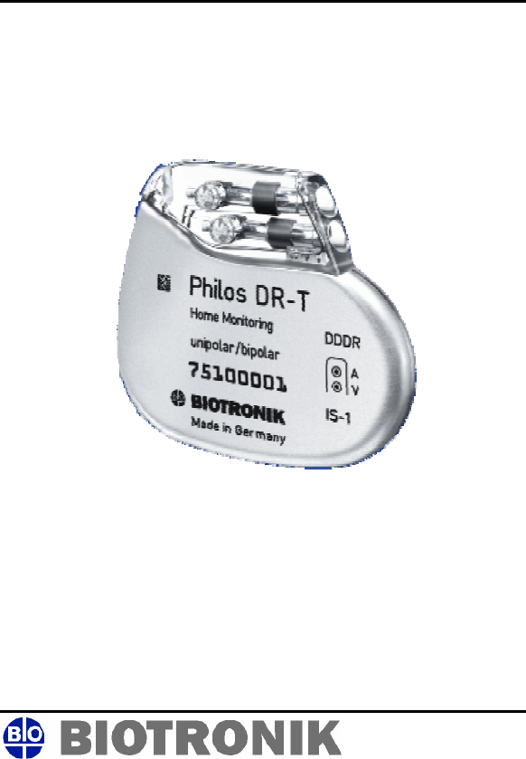
Philos DR-T
Implantable Pulse Generator
Philos DR-T
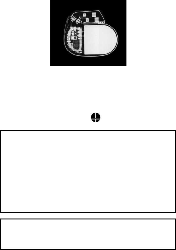
X-Ray identification
Radiopaque Identification
A radiopaque identification code is visible on standard x-ray, and
identifies the pulse generator:
Philos DR-T VV
CAUTION
Because of the numerous available 3.2-mm configurations
(e.g., the IS-1 and VS-1 standards), lead/pulse generator
compatibility should be confirmed with the pulse generator
and/or lead manufacturer prior to the implantation of a pacing
system.
IS-1, wherever stated in this manual, refers to the
international standard, whereby leads and generators from
different manufacturers are assured a basic fit. [Reference
ISO 5841-3:1992(E)].
CAUTION
Federal (U.S.A.) law restricts this device to sale by or on the
order of, a physician (or properly licensed practitioner).
©2004 BIOTRONIK, Inc., all rights reserved.

Philos DR-T Technical Manual i
Contents
1. Home Monitoring-Overview ................................................1
1.1 Home Monitoring ..............................................................1
1.2 Transmission of Information .............................................1
1.3 Patient Device with Components......................................2
1.4 Receiving Patient Data .....................................................3
2. Indications and Contraindications.....................................5
3. Warnings and Precautions..................................................7
3.1 Home Monitoring ..............................................................7
4. Types of Messages ............................................................11
4.1 Event Message ...............................................................11
4.2 Trend Message ...............................................................13
4.3 Patient Message .............................................................13
5. Description of Transmitted Data.......................................15
5.1 The Monitoring Interval ...................................................15
5.2 Heart Rate.......................................................................15
5.3 Atrial Rhythm ..................................................................15
5.4 Ventricular Rhythm .........................................................15
5.5 AV Conduction ................................................................16
5.6 System Status .................................................................16
6. Technical Data ....................................................................17
6.1 Modes .............................................................................17
6.2 Home Monitoring Parameters.........................................17
6.3 Pulse and Control Parameters .......................................18
6.3.1 Rate Adaptation ......................................................21
6.3.2 Parameters at Replacement Indication ..................21
6.3.3 Additional Functions................................................23
6.4 Programmers ..................................................................24
6.5 Materials in Contact with Human Tissue ........................24
6.6 Electrical Data/Battery ....................................................24
6.7 Mechanical Data .............................................................25
7. Order Information ..............................................................27

ii Philos DR-T Technical Manual
CAUTION
Federal (U.S.A.) law restricts this device to sale by, or on the
order of, a physician (or properly licensed practitioner).

Philos DR-T Technical Manual 1
1. Home Monitoring-Overview
Philos DR-T offers the complete functionality of a DDDR
pacemaker while being equipped with the additional features
associated with Home Monitoring. Consult the Philos technical
manual for a description and overview of the standard
pacemaker functionality of the Philos DR-T.
1.1 Home Monitoring
Home Monitoring is a novel system, which enables the exchange
of information about a patient’s cardiac status between implant,
patient, and physician. Home Monitoring can be used to provide
the physician with advance reports from the implant and process
them into graphical and tabular formats. This information helps
the physician optimize the therapy process, as it may result in
the patient being scheduled for additional clinical appointments
between regular follow-up visits if necessary.
The implant’s Home Monitoring function can be used for the
entire operational life of the implant (prior to ERI) or for shorter
periods, such as several weeks or months.
1.2 Transmission of Information
The implant transmits information with a small transmitter, which
has a range of about 2 meters. The patient’s implant data are
sent daily to the corresponding patient device (i.e.,
CardioMessenger) at a configurable time. The transmissions
may also be activated by the patient with the application of a
magnet over the implant and by certain cardiac events, as
programmed. The types of transmissions are discussed in
Section 4.
The minimal distance between the implant and the patient device
must be 15 cm.
2 Philos DR-T Technical Manual
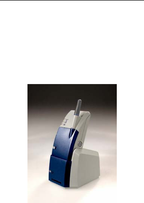
1.3 Patient Device with Components
The patient device (Figure 1) is designed for use in the home
and is comprised of the mobile device and the associated
charging station. The patient can carry the mobile device with
them during his or her occupational and leisure activities. The
patient device comes with a rechargeable battery that has an
approximate operational time of 24 hours after a charge time of 5
hours. It receives information from the implant and forwards it
via the mobile network to a BIOTRONIK Service Center.
For additional information about the patient device, please refer
to its manual.
Figure 1: Patient Device with Charging Stand
(CardioMessenger)

Philos DR-T Technical Manual 3
1.4 Receiving Patient Data
The implant’s information is digitally formatted by the
BIOTRONIK Service Center and processed into a concise report
called a Cardio Report. The Cardio Report, which is adjusted to
the individual needs of the patient, contains current and previous
implant data. The Cardio Report is sent to the attending
physician via fax or is available on the Internet, which is selected
during registration of the patient. For more information on
registering for Home Monitoring, contact your BIOTRONIK sales
representative.
The password protected BIOTRONIK Home Monitoring website
can be accessed by registered users at the following URL:
www.biotronik-homemonitoring.com
An online help menu is available in order to assist with the use of
the Home Monitoring website.
Use of the Internet for reviewing Home Monitoring data must be
in conjunction with the system requirements listed in Table 1.
Additionally, Table 1 provides system specifications that are
recommended for optimizing usage of the Internet.

4 Philos DR-T Technical Manual
Table 1: System Requirements / Recommendations
System
Requirements
System
Recommendations
(for Optimal Usage)
Screen
Resolution
800 x 600 ≥ 1024 x 768
Internet
Bandwidth
56 kB/sec ≥ 128 kB/sec
(DSL, cable modem)
PC 600 MHz, 128
MB RAM
N/A
Internet Browser MS Internet
Explorer 5.0
- or -
Netscape
Navigator 4.72
≥ MS Internet Explorer
5.5
- or -
≥ Netscape 7/Mozilla
Acrobat Reader Version 4 Version 5 or higher
Communication
Channel
Fax (G3) or
e-mail
Fax (G3), e-mail or
mobile phone
Additionally, the attending physician may register to be informed
of the occurrence of an Event Triggered Message through email
or SMS (i.e., mobile phone) with a brief text message. If
registered for Internet availability, the patient’s detailed implant
data can then be viewed by logging onto the Home Monitoring
website.

Philos DR-T Technical Manual 5
2. Indications and
Contraindications
For the general indications and contraindications, please refer to
the Philos Family technical manual. The indications and
contraindications of the Philos DR-T are identical to those of the
rate adaptive dual chamber Philos DR pulse generator.

6 Philos DR-T Technical Manual

Philos DR-T Technical Manual 7
3. Warnings and Precautions
Certain therapeutic and diagnostic procedures may cause
undetected damage to a pulse generator, resulting in
malfunction or failure at a later time. Please note the following
warnings and precautions:
Magnetic Resonance Imaging (MRI) – Avoid use of magnetic
resonance imaging as it has been shown to cause movement of
the pulse generator within the subcutaneous pocket and may
cause pain and injury to the patient and damage to the pulse
generator. If the procedure must be used, constant monitoring is
recommended, including monitoring the peripheral pulse.
Rate-Adaptive Pacing – Use rate-adaptive pacing with care in
patients unable to tolerate increased pacing rates.
High Output Settings – High output settings combined with
extremely low lead impedance may reduce the life expectancy of
the pulse generator to less than 1 year. Programming of pulse
amplitudes, higher than 4.8 V, in combination with long pulse
widths and/or high pacing rates may lead to premature activation
of the replacement indicator.
3.1 Home Monitoring
Patient’s Ability – Use of Home Monitoring requires the patient
and/or caregiver to follow the system instructions and cooperate
fully when transmitting data.
If the patient cannot understand or follow the instructions
because of physical or mental challenges, another adult who can
follow the instructions will be necessary for proper transmission.
Cellular Phone Availability – Home Monitoring is not practical
for patients who live in areas where cellular telephone networks,
utilizing the GSM standard, are not available or are not likely to
become available in the near future.

8 Philos DR-T Technical Manual
Electromagnetic Interference (EMI) – Precautions for EMI
interference with the Philos DR-T pulse generator are provided
in the Philos technical manual in section 4.5. Sources of EMI
including cellular telephones, electronic article surveillance
systems, and others are discussed therein.
Use in Cellular Phone Restricted Areas – The mobile patient
device (transmitter/receiver) should not be utilized in areas
where cellular phones are restricted or prohibited (i.e.,
commercial aircraft).
Event Triggered Message – A timely receipt of the
corresponding event report cannot be guaranteed. The receipt
is also dependent on whether the patient was physically situated
in the required coverage range of the patient device at the time
the event information was sent.
Patient-Activated Message – The magnet effect must be
programmed “synchronous” if the [Patient Message] function is
activated. Otherwise, this function will not be available.
Not for Diagnosis – The data transmitted by Home Monitoring
are not suitable for diagnosis, because not all information
available in the implant is being transmitted.
Follow-Ups – When using Home Monitoring, the time period
between follow-up visits may not be extended.
The use of Home Monitoring does not replace regular follow-up
examinations. The data transmitted via Home Monitoring are not
suitable for a conclusive diagnosis.
Magnet Effect – The magnet effect must be programmed
“synchronous” if the attending physician enables the patient to
transmit messages.
Lead Connection – Because of the numerous available 3.2-mm
configurations (e.g., the IS-1 and VS-1 standards), lead/pulse
generator compatibility should be confirmed with the pulse
generator and/or lead manufacturer prior to the implantation of a
pacing system.
IS-1, wherever stated in this manual, refers to the international
standard, whereby leads and generators from different
manufacturers are assured a basic fit. [Reference
ISO 5841-3:1992(E)].

Philos DR-T Technical Manual 9
Consult the Philos manual for additional warnings and
precautions associated with this device.

10 Philos DR-T Technical Manual

Philos DR-T Technical Manual 11
4. Types of Messages
When the Home Monitoring function is activated, the
transmission of a message from the implant can be triggered as
follows:
• Trend Message – the time period (daily) initiates the
report
• Event Message – the pacemaker detects certain events,
which initiate a message immediately
• Patient Message – the patient initiates transmission of a
message
The attending physician decides whether or not the patient will
be able to initiate the transmission of a message on their own
through application of a magnet. Transmissions initiated through
magnet application do not affect event or trend message
transmissions.
4.1 Event Message
When certain cardiac and technical events are detected by the
implant, a message transmission is automatically triggered. This
is described as an “event message”.

12 Philos DR-T Technical Manual
The following cardiac and technical events initiate a report:
• Atrial Lead Check < 300 and > 3000 Ohm
• Ventricular Lead Check < 300 and > 3000 Ohm
• Ventricular Bursts (Runs)
• Ventricular Events (Episodes)
• Low P-Wave Amplitude1 (< 50% safety margin)
• Low R-Wave Amplitude1 (< 50% safety margin)
• ERI Activation
• 1
st Mode Switch/24 hours
WARNING
A timely receipt of the corresponding event report cannot be
guaranteed. The receipt is also dependent on whether the
patient was physically situated in the required coverage
range of the patient device at the time the event information
was sent.
NOTE:
When ERI mode is reached, this status is transmitted.
Further measurements and transmissions of Home
Monitoring data are no longer possible.
NOTE:
The attending physician must notify the BIOTRONIK Service
Center about which of these events he/she wishes to be
informed.
1 Examples: The programmed sensitivity is 1.0 mV.
A) Average of the measured P/R-Wave amplitudes is 2.6 mV. Therefore,
measured value is greater than 100% of the safety margin. Event message is
not triggered.
B) Average of the measured P/R-Wave amplitudes is 1.9 mV. Therefore,
measured value is less than 100%, but greater than 50% of the safety margin.
Event message is not triggered.
C) Average of the measured P/R-Wave amplitudes is 1.4 mV. Therefore,
measured value is smaller than 50% of the safety margin. As a result, an event
message is triggered.

Philos DR-T Technical Manual 13
4.2 Trend Message
An additional type of message is the programmable “Trend
Message”. Trend messages occur at a programmable time of
transmission (i.e., at the end of the Monitoring Interval). The
time can be set anywhere between 0:00 and 23:50 hours. It is
recommended that you select a time during the late night or
early morning hours (between 0:00 and 4:00), or other time
when the patient is usually in his or her home.
The length of the time interval (monitoring interval) is not
programmable – it is preset to “daily”.
4.3 Patient Message
It is possible to trigger a transmission through magnet
application over the pacemaker. The attending physician must
inform the patient in detail about operating the device and about
the physical symptoms which would warrant a magnet
application by the patient.
WARNING
The magnet effect must be programmed “synchronous” if
the [Patient Message] function is activated. Otherwise, this
function will not be available.

14 Philos DR-T Technical Manual

Philos DR-T Technical Manual 15
5. Description of Transmitted
Data
The following data are transmitted by Home Monitoring, when
activated. In addition to the medical data, the serial number of
the implant is also transmitted.
5.1 The Monitoring Interval
The monitoring interval is considered the time period since the
last trend message was transmitted. For a trend message, the
monitoring interval since the previous trend message is set at
24 hours. For an event or patient message, the monitoring
interval would typically be less than 24 hours. This occurs when
these messages are sent after the programmed transmission
time of the trend message.
5.2 Heart Rate
• Average (mean) ventricular heart rate (bpm)
5.3 Atrial Rhythm
• Intrinsic rhythm (As / Ax) (%)
• Number of Mode Switching
• Duration of Mode Switching (%)
5.4 Ventricular Rhythm
• Intrinsic rhythm (Vs/ Vx) (%)
• Ventricular rate at Mode Switching (bpm)
• Number of ventricular runs (4...8 sequential VES)
• Number of ventricular events (more than 8 sequential
VES), defined as a ventricular episode
• Duration of the longest ventricular event (sec)

16 Philos DR-T Technical Manual
5.5 AV Conduction
• AV Synchronicity (Ax Vx/Vx) (%)
− with intrinsic rhythm (AsVs) (%)
− with atrial stimulation (ApVs) (%)
− with ventricular stimulation (AsVp) (%)
− with dual-chamber stimulation (ApVp) (%)
5.6 System Status
• Atrial lead check
• Ventricular lead check
• Mean P-Wave amplitude / programmed sensitivity (%)
• Mean R-Wave amplitude / programmed sensitivity (%)
• Battery status
NOTE:
Atrial and Ventricular Lead Check must be programmed ON
to enable Home Monitoring functionality of this data.

Philos DR-T Technical Manual 17
6. Technical Data
6.1 Modes
The following modes are available in the Philos DR-T when
Home Monitoring is deactivated:
DDDR, DDTR/A, DDTR/V, DDTR, DDIR, DDIR/T, DVIR, DVTR,
DOOR, VDDR, VDTR, VDIR, VVIR, VVTR, VOOR, AAIR, AATR,
AOOR, DDD, DDT/A, DDT/V, DDT, DDI, DDI/T, DVI, DVT, DOO,
VDD, VDT, VDI, VVI, VVT, VOO, AAI, AAT, AOO, OFF
The Home Monitoring function is available for the following
pacing modes:
DDDR, DDTR/A, DDTR/V, DDTR, DDIR, DDIR/T, VDDR, VDTR,
VDIR, DDD, DDT/A, DDT/V, DDT, DDI, DDI/T, VDD, VDT, VDI
NOTE:
Bold parameters indicate factory settings.
6.2 Home Monitoring Parameters
Home Monitoring
Off, On
Monitoring Interval
1 day
Time of Transmission
0:00...(10)...23:50 hours
Patient Message
Off, On
Event Message
Off, On

18 Philos DR-T Technical Manual
6.3 Pulse and Control Parameters
Basic rate
30...(1)...60...(1)...88...(2)...122...(3)...140...(5)...180 ppm
Night rate
Off, 30...(1)...60...(1)...88...(2)...122...(3)...140...(5)...180 ppm
Rate Hysteresis
Off; -5...(5)...-50 bpm
Repetitive Hysteresis
Off; 1…(1)…10
Scan Hysteresis
Off: 1…(1)…10
Upper Tracking Rate (UTR)
100; 110; 120; 130; 140; 160; 185 ppm
UTR Response
2:1; WRL (automatic selection)
Rate Limitation2,3,4
190…220 ppm
Dynamic AV Delay (Dual chamber only)
low; medium; high; individual; fixed
AV Delay Values (Dual chamber only)
15; 50; 75; 100; 120...(10)...200; 225; 250; 300 ms
(Programmable in 5 ranges)
2 The corresponding intervals t correlate with the rates f by the formula t = 60.000
/ f (t in ms, f in ppm).
3 In the event of electronic defect.
4 Rate Limitation changes as the Pacemaker approaches End of Service. The
Rate Limitation is nominally 190 ppm at Beginning of Service (BOS) and can
reach 220 ppm at End of Service (EOS) due to battery depletion.

Philos DR-T Technical Manual 19
AV Hysteresis
Off; low; medium; high
AV Repetitive Hysteresis
Off; 1...(1)...6
AV Scan Hysteresis
Off; 1...(1)...6
AV safety delay (Dual chamber only)
100 ms
Sense Compensation
Off; -15...(15)...-120 ms
Ventricular Blanking Time
16; 24; 32; 40; 48; 56; 72 ms
Magnet effect
Automatic; asynchronous; synchronous
Asynchronous Magnet Effect: paces at 90 ppm.
Automatic Magnet Effect; 10 cycles at 90 ppm
asynchronous; thereafter synchronous with the programmed
basic rate
Synchronous Magnet Effect; synchronous with programmed
basic rate
Pulse amplitude
A 0.1...(0.1)...3.6...(0.1)...4.8...(1.2)...8.4 V
V 0.1...(0.1)...3.6...(0.1)...4.8...(1.2)...8.4 V
Ventricular Pulse Amplitude for Safe Program
4.8V
Pulse width
A 0.1; 0.2; 0.3; 0.4; 0.5; 0.75; 1.0; 1.5 ms
V 0.1; 0.2; 0.3; 0.4; 0.5; 0.75; 1.0; 1.5 ms

20 Philos DR-T Technical Manual
Sensitivity
A 0.1...(0.1)...1.0...(0.1)…1.5…(0.5)...7.5 mV
V 0.5...(0.5)...2.5...(0.5)...7.5 mV
Refractory period5
A 200...(25)…425...(25)...775 ms
V 170, 195, 220, 250; 300; 350; 400 ms
PVARP (minimum)
Off, dependent on TARP and AV Delay settings
ARP Extension
0...(50)...350 ms
Lead Check
Off; On
Automatic Mode Conversion
Off; On (in modes DDD(R), DDT(R)/A, DDT(R)/V, and VDD(R))
Mode Switch (X out of Y)
Off; On (in modes DDD(R), DDT(R)/A, DDT(R)/V and VDD(R))
X = 3...(1)...8
Z = 3...(1)...8
Lead Polarity
Pace: A unipolar; bipolar
V unipolar; bipolar
Sense: A unipolar; bipolar
V unipolar; bipolar
Far-Field Blanking
50...(25)...200 ms
5 In the DDIR, VVIR and VOOR modes, lower maximum sensor rates result than indicated
here (partly depending on the selected AV interval). The correct values are indicated by
the programmer.

Philos DR-T Technical Manual 21
PMT Management
Off; On
6.3.1 Rate Adaptation
Sensor gain
1.0, 1.1, 1.3, 1.4, 1.6, 1.8, 2.0, 2.2, 2.6, 3.0, 3.3, 3.7, 4.0, 4.5,
5.0, 6.0, 7.0, 8.0, 8.5, 10, 11, 12, 14, 16, 18, 20, 22, 24, 28, 32,
35, 40
Sensor threshold
very low; low; mean; high; very high
Rate increase
1, 2, 4, 8 ppm/s
Maximum sensor rate
80...(5)...180 ppm
Rate decrease
0.1, 0.2, 0.4, 0.8 ppm/s
Automatic Sensor Gain
Off; On
6.3.2 Parameters at Replacement Indication
Basic Rate
Programmed value minus 11%
(in modes DVI(R), DDI(R), DVT(R), DDI/T(R) minus 4.5–11%,
depending on programmed AV Delay)
Magnet Rate
The magnet rate in all modes decreases as shown in the
following table.

22 Philos DR-T Technical Manual
Magnet Mode Cycles 1-10 after
magnet
application
After Cycle 10
Automatic Asynchronous,
basic rate at 80 ppm
Synchronized with
basic rate reduced
by 4.5 - 11%
Asynchronous Asynchronous,
basic rate at 80 ppm
Asynchronous with
basic rate at 80
Synchronous Synchronized with
basic rate reduced
by 4.5 - 11%
Synchronized with
basic rate reduced
by 4.5 - 11%
Pulse Widths
Programmed values
Sensitivities
Programmed values

Philos DR-T Technical Manual 23
6.3.3 Additional Functions
Home Monitoring
Additional functions conform with Philos DR:
• Temporary Program Activation
• High Precision Threshold test in the range of 0.1 up to
4.8 V with 0.1 V resolution
• PAC (pulse amplitude control) system produces
consistent pulses
• Analog Telemetry with measuring of battery, pulse and
lead data
• Two channel Real Time IEGM Transmission with
markers
• Patient Data Memory
• Sensor Simulation
• Position Indicator for the programmer head
• 24 hour Trend
• Heart Rate Histogram
• Sensor Rate Histogram
• Sensor Test Trend with complete Rate Forecast
• Automatic Sensor Gain with Trend Monitor
• VES Analysis
• AES Analysis
• Retrograde Conduction Test
• Automatic Mode Conversion
• Mode Switching
• PMT Management
• Activity Report
• Event counter
• P-/R-wave Tests with Trend Data
• External Pulse Control up to 800 ppm
• Night Program

24 Philos DR-T Technical Manual
• Arrhythmia Detection Recordings (note that only 3 ADRs
can be stored by the Philos DR-T; however, 10 can be
stored by the Philos DR)
• Lead Impedance Trends
• Lead Check
6.4 Programmers
Home Monitoring functions and their parameters can be
configured with the following programming devices:
EPR 1000PLUS, TMS 1000PLUS
6.5 Materials in Contact with Human
Tissue
Housing: Titanium
Connector receptacle: Epoxy resin
Sealing Plugs: Silicone Rubber
Coating for unipolar devices: Silicone Rubber
6.6 Electrical Data/Battery
NOTE:
At 37ºC, with pacing impedance of 500 Ohms.
ELECTRICAL DATA
Circuit
Hybrid electronics with VLSI CMOS Chip
Input Impedance
A 240 kOhm
V 240 kOhm
Pulse Form
biphasic, asymmetric

Philos DR-T Technical Manual 25
Polarity
cathodic
Power Consumption
BOS, inhibited: 14 µA
BOS, 100 % pacing: 22 µA
Conducting Surface
uncoated: 32.8 cm2
coated: 7.23 cm2
Conducting Shape
uncoated: flattened ellipsoidal
coated: ellipsoidal
BATTERY
Power Source
Li/I
Open-Circuit Voltage
2.8 V
Voltage at ERI
2.5 V
Nominal Capacity6
1.3 Ah
6.7 Mechanical Data
Lead Connector
IS-1 (accepts unipolar and bipolar)
Weight
27 g
6 Battery manufacturer’s specification.

26 Philos DR-T Technical Manual
Volume
12 cm3
Dimensions
6 x 44 x 51 mm
X-Ray Identification
VV
Philos DR-T Technical Manual 27
7. Order Information
Product Name Order Number
Philos DR-T 331 440

Distributed by:
BIOTRONIK, Inc.
6024 Jean Road
Lake Oswego, OR 97035-5369
(800) 547-0394 (24-hour)
(503) 635-9936 (FAX)
Manufactured by:
BIOTRONIK GmbH & Co. KG
Woermannkehre 1
D-12359 Berlin Germany
M4064-C 7/04